
SECTION 2A - TS SERIES ASTRA BODY KIT
1. GENERAL INFORM ATION
This Section of the Holden By Design Service Information Supplement describes the service procedures for the
aerodynamic id body sty ling kit components available for TS Astra Series Vehicles.
The id body styling kit c onsists of a newly designed integral front bum per fac ia / spoiler, rear bum per extension and
rear hatch spoiler. The original side skirts are modified to integrate with the styling package.
Alloy wheels, a chrom e ex haust extens ion, id and Holden By Design badging and a Holden By Design identification
plate are also included as part of the package.
NOTE: Vehicles can be supplied with only the rear spoiler or alloy wheels. In these instances no Holden By Design
identification or badging is included.
Figure 2A-1 illustrates the TS Astra id body kit major components.
For information not contained in this Supplement, refer to the Holden Astra on TIS 2000.
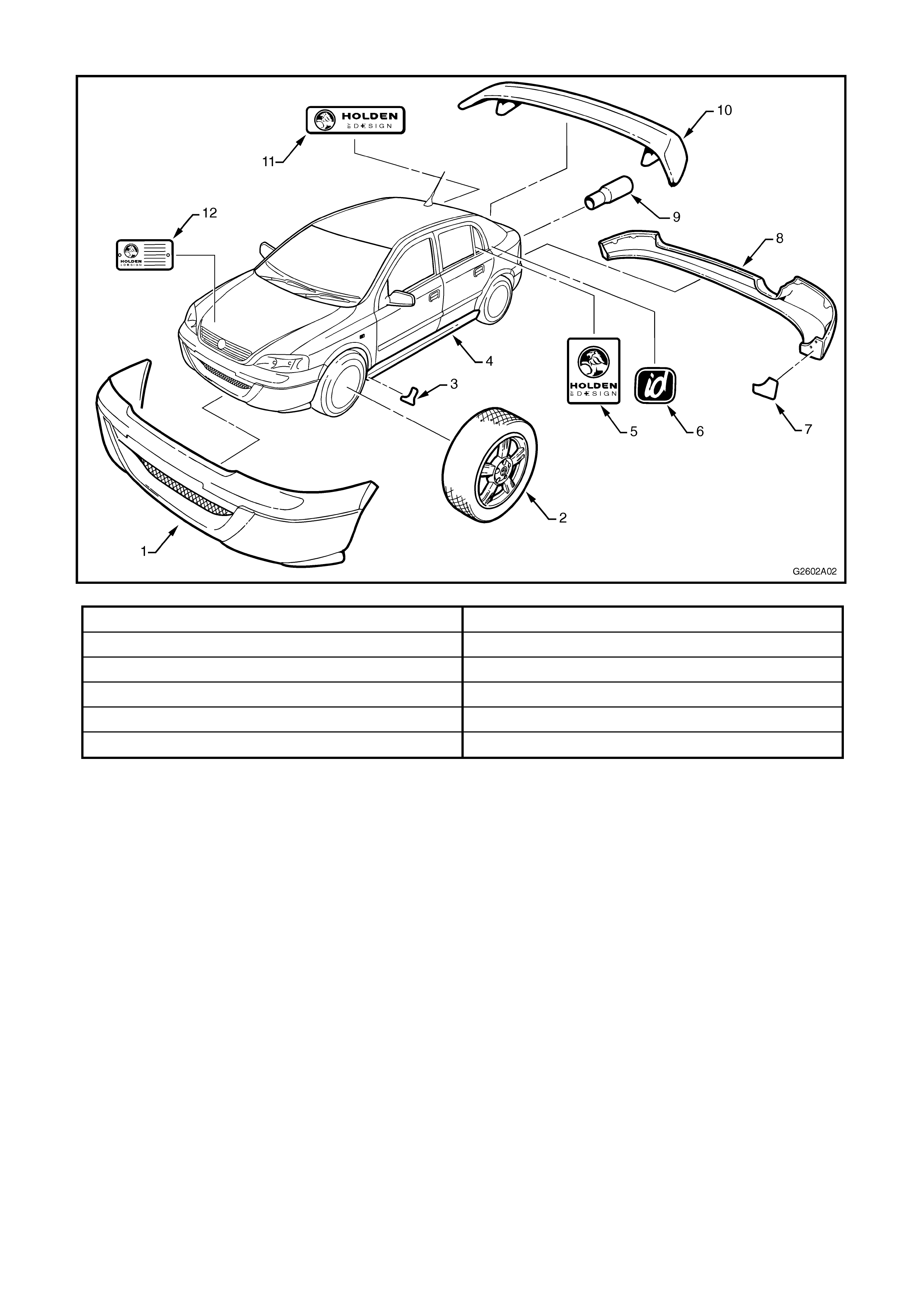
1.1 MAJOR COMPONENTS
Figure 2A-1
1. Front bumper facia 7. Rear bumper extension 3M stone chip film
2. Alloy wheel 8. Rear bumper extension
3. Side skirt 3M stone chip film 9. Exhaust extension
4. Side skirt (original part modified) 10. Rear spoiler
5. Holden By Design decal 11. Holden By Design emblem
6. id emblem 12. Holden By Design identification plate
2. FRONT BUMPER FACIA
A completely new front bumper facia is used which
replaces the original facia and includes an integral
front spoiler.
The bumper facia is painted in the vehicle’s body
colour. A replacement part is supplied unpainted and
will require painting prior to fitment. The painting
procedures are relatively straight forward, providing
the correct steps for refinishing PUR-RIM material
are followed.
As materials and techniques will vary depending on
the brand of paint us ed, painting procedures are not
provided in this Supplement. Refer to your paint
supplier if further information is required.
To accommodate access to the tow hook mount, a
cover is provided in the facia as shown.
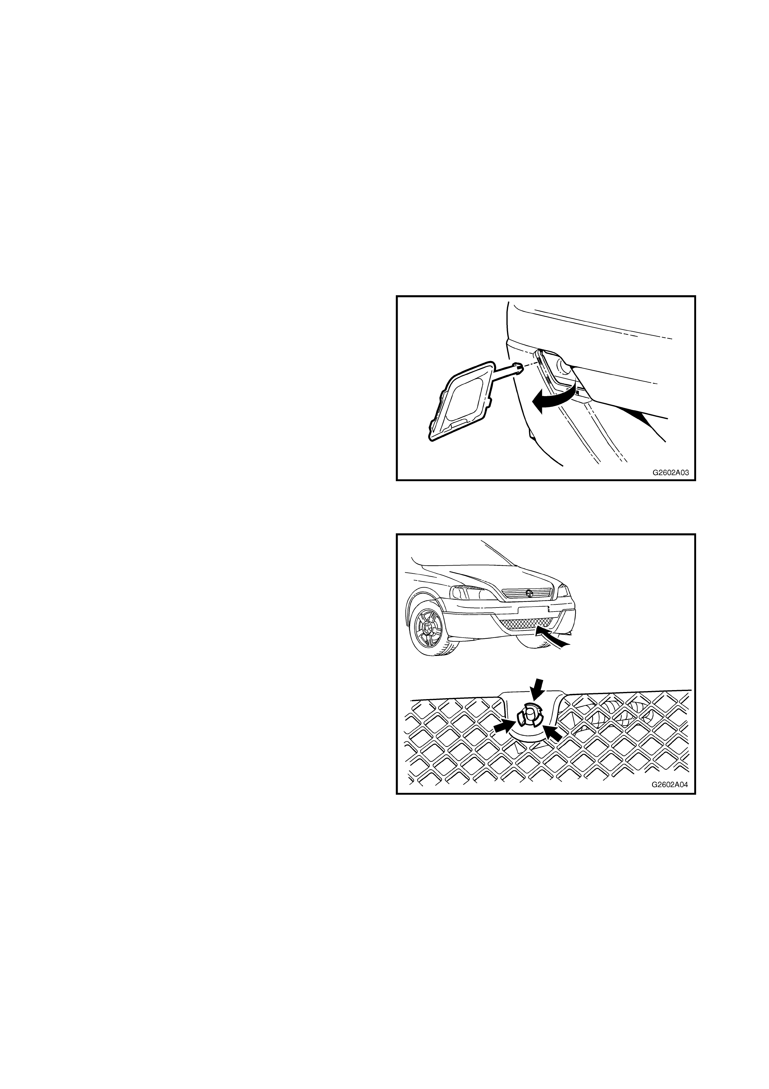
Figure 2A-2
REMOVE
1. Remove the ambient temperature sensor by
depressing the tabs as shown and pushing the
sensor through the hole.
2. Remove the three scrivets (1), four Torx head
screws (2 & 3) and two scrivets (4) attac hing the
bumper facia to the vehicle, refer Fig. 2A-4.
3. Remove the bumper facia from the vehicle
ensuring to unclip the lug (5) from each side.
4. If the bumper f ac ia is not damaged, plac e it on a
soft surface to avoid scratches.
Figure 2A-3

Figure 2A-4
DISASSEMBLE
1. From the rear of the bumper facia, remove the
seven screws (1) and remove the wire mesh (2).
Figure 2A-5
INSTALL
1. Fit wire mesh to bumper facia with seven
screws as shown in Fig. 2A-5.
NOTE: If the new facia does not have screw holes,
drill a hole in each landing with a 2 mm drill bit.
2. Install facia onto vehicle ensuring the lugs (5)
are clipped into place, refer Fig. 2A-4.
3. Fit screws and scrivets as shown in Fig. 2A-4
and ensure bumper facia is correctly aligned.
3. SIDE SKIRTS
The original rocker panel side skirt assemblies are
integrated with the Holden By Design id kit by coating
the skirts with ‘Hi-Fill’ primer, which fills the grain of the
plastic material and provides a smooth finish. They are
then painted in the vehicle’s body colour.
Replacement parts are supplied unpainted and will
require f illing with a suitable Hi-Fill pr imer and painting
prior to fitment.
The painting procedures are relatively straight forward
providing the correct steps for refinishing
Polypropylene (PP) material are followed.
As materials and techniques will vary depending on
the brand of paint used, painting procedures are not
provided in this Supplement. Refer to your paint
supplier if further information is required.
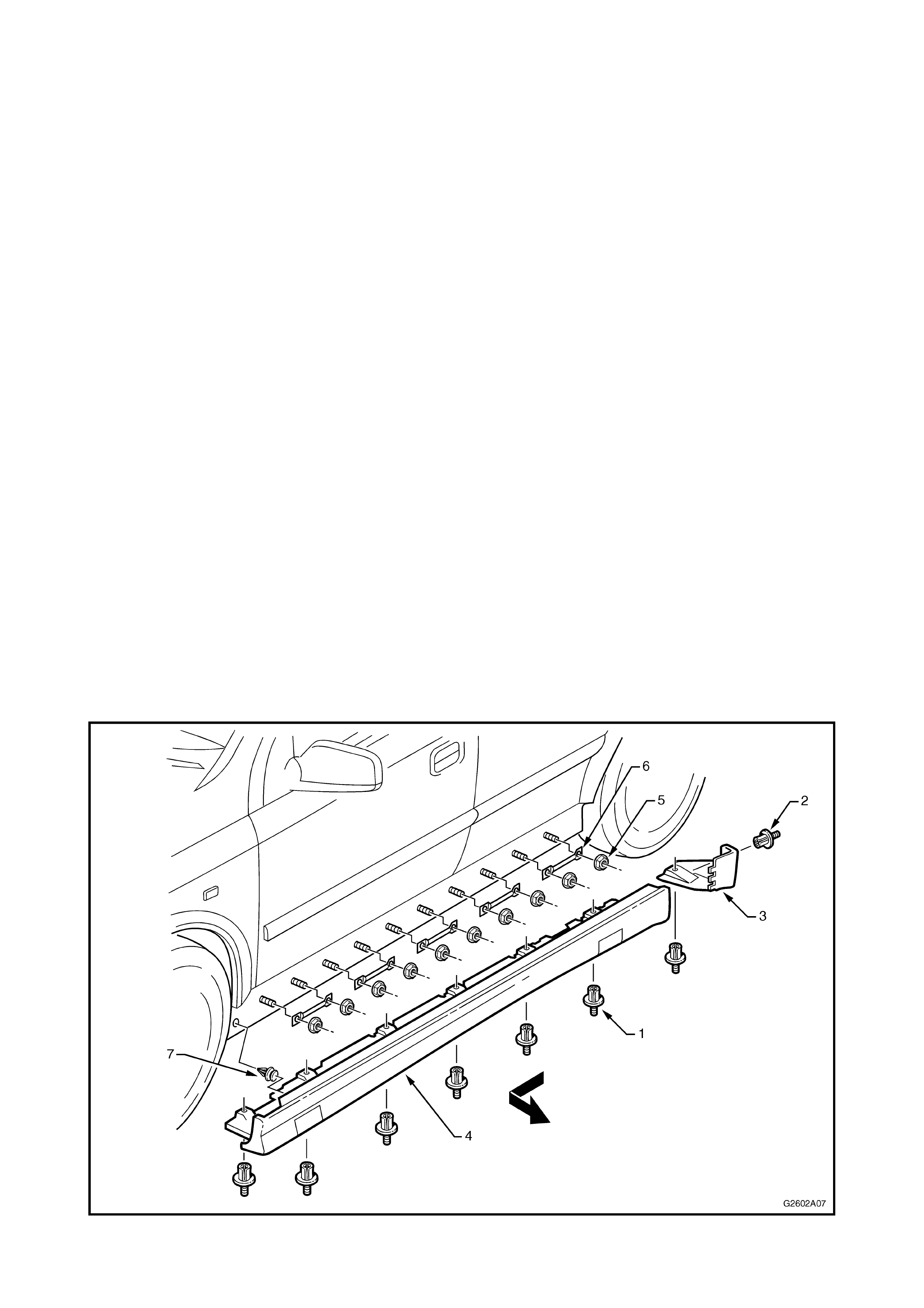
REMOVE
1. Remove the scrivets (1 & 2) attaching the side
skirt to the vehicle, refer Fig. 2A-6.
NOTE: The centre pins of the scrivets do not have
heads, therefore the pin must be pushed inwards to
allow removal of the outer section. New scrivets will
be required on installation.
2. Remove the end cap (3) by sliding rearwards.
3. Remove the side skirt by first tapping the skirt
forward, then carefully unclipping it from the
vehicle in the direction shown.
4. If required, remove the nuts (5) attaching the
retain ers (6).
5. The retainer clip (7) may be left behind on
removal of the skirt and should be removed from
the vehicle.
Figure 2A-6
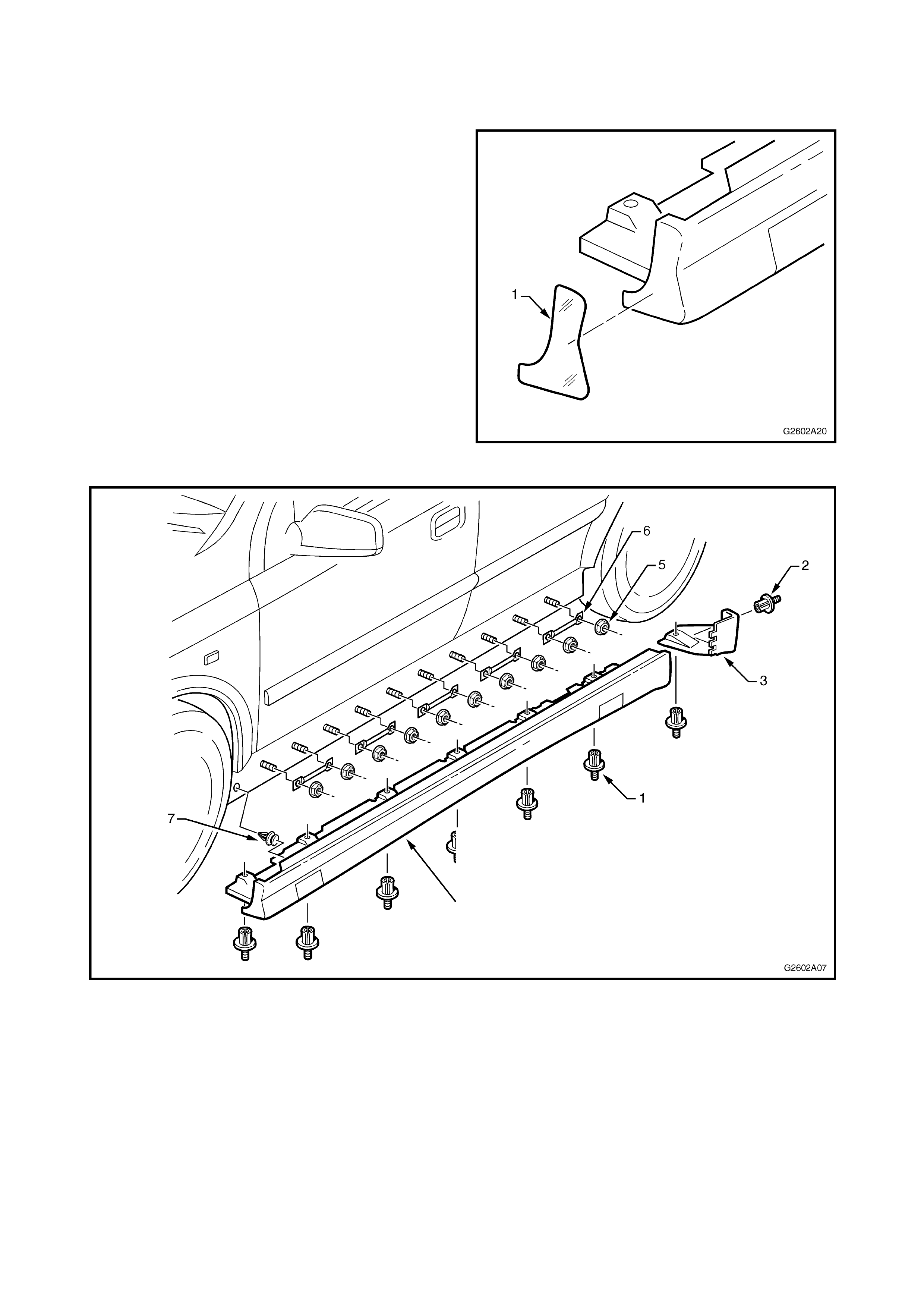
INSTALL
1. If required, paint the replacement part. Use Hi-
Fill primer to fill the grain of the polypropylene
and achieve a smooth finish.
2. Apply 3M stone chip film (1) to the front of the
sk irt as shown. Smooth out all trapped air as the
film is being applied.
NOTE: Ensure ar ea is clean and free of dirt, grease
and finger marks prior to affixing the film.
3. Ensure the retaining clip (7) is fitted into the
skirt, refer Fig. 2A-8.
4. If required fit the retainers (6) and nuts ( 5) to the
vehicle.
5. Align the skirt in position with the vehicle and
clip it in place by tapping at each retainer (6 &
7).
6. Fit the end cap (3) into the skirt by sliding it
forward, ensuring the tabs seat correctly in the
skirt.
7. Insert all scrivets, pushing their centre pin in
until flush with the outer head. Figure 2A-7
Figure 2A-8
4. REAR BUMPER EXTENSION
The rear bumper extension is secured to the rear
bumper facia with screws. Removal of the bumper
extension will necessitate rear bumper facia removal,
which is described below.
The rear bumper extension is painted in the vehicle’s
body colour. A replacement part is supplied unpainted
and will require painting prior to fitment.
The painting procedures are relatively straight forward,
providing the correct steps for refinishing PUR-RIM
material are followed.
As materials and techniques will vary depending on the
brand of paint used, painting procedures are not
provided in this Supplement. Ref er to your paint supplier
if further information is required.
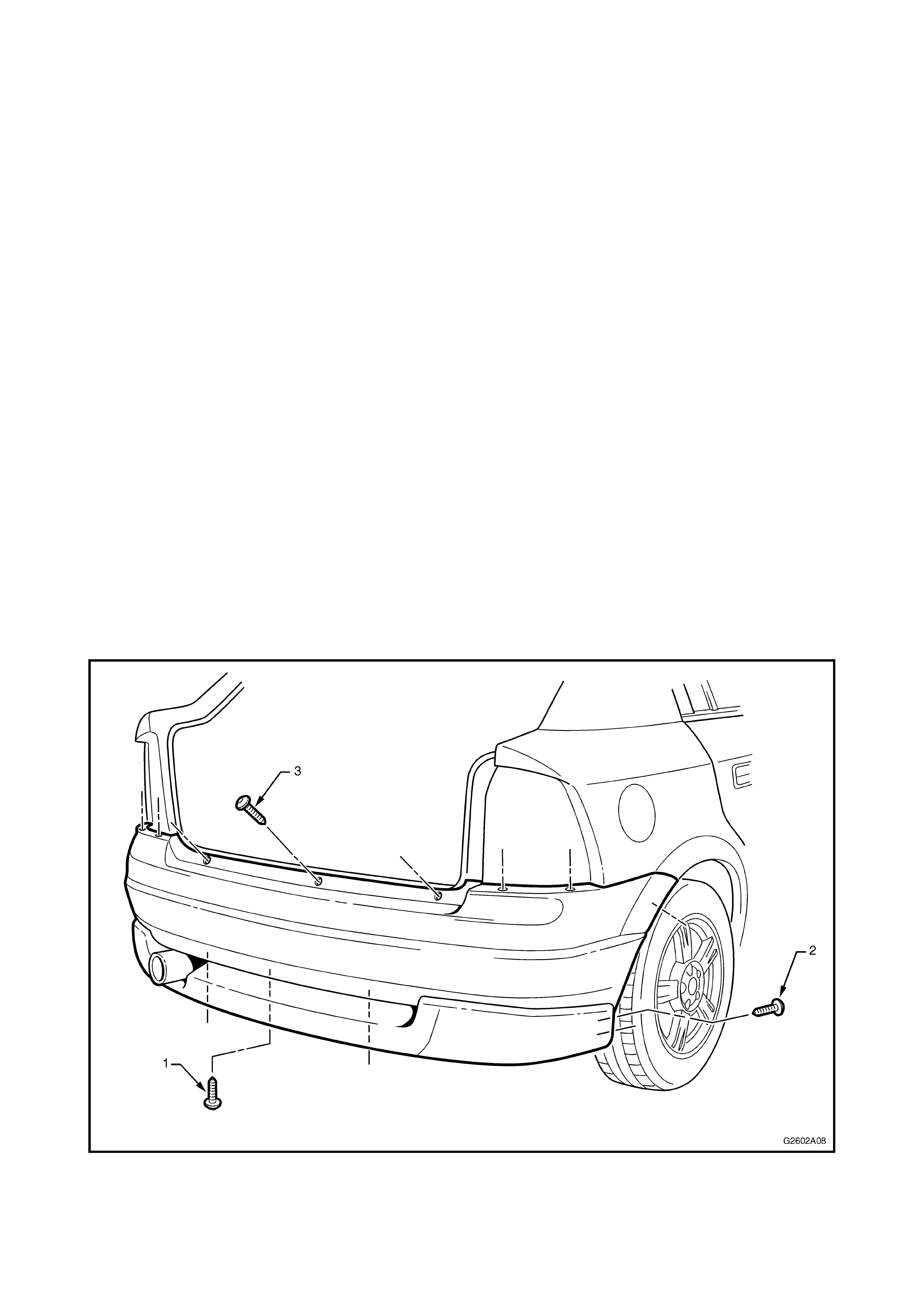
REMOVE
1. Remove the tail lights by opening the access
cover inside the rear compartment and
removing the two thumb screws. Refer to
Service Instructions, Group N for Astra on TIS
2000, if further information is required.
2. Remove the Torx head screws (1) three places,
(2) three places each side and (3) seven places.
3. Remove the bumper facia and extension
assembly from the vehicle, sliding it over the
exhaust extension.
NOTE: When access is achieved, disconnect the
number plate light wiring connector.
Figure 2A-9
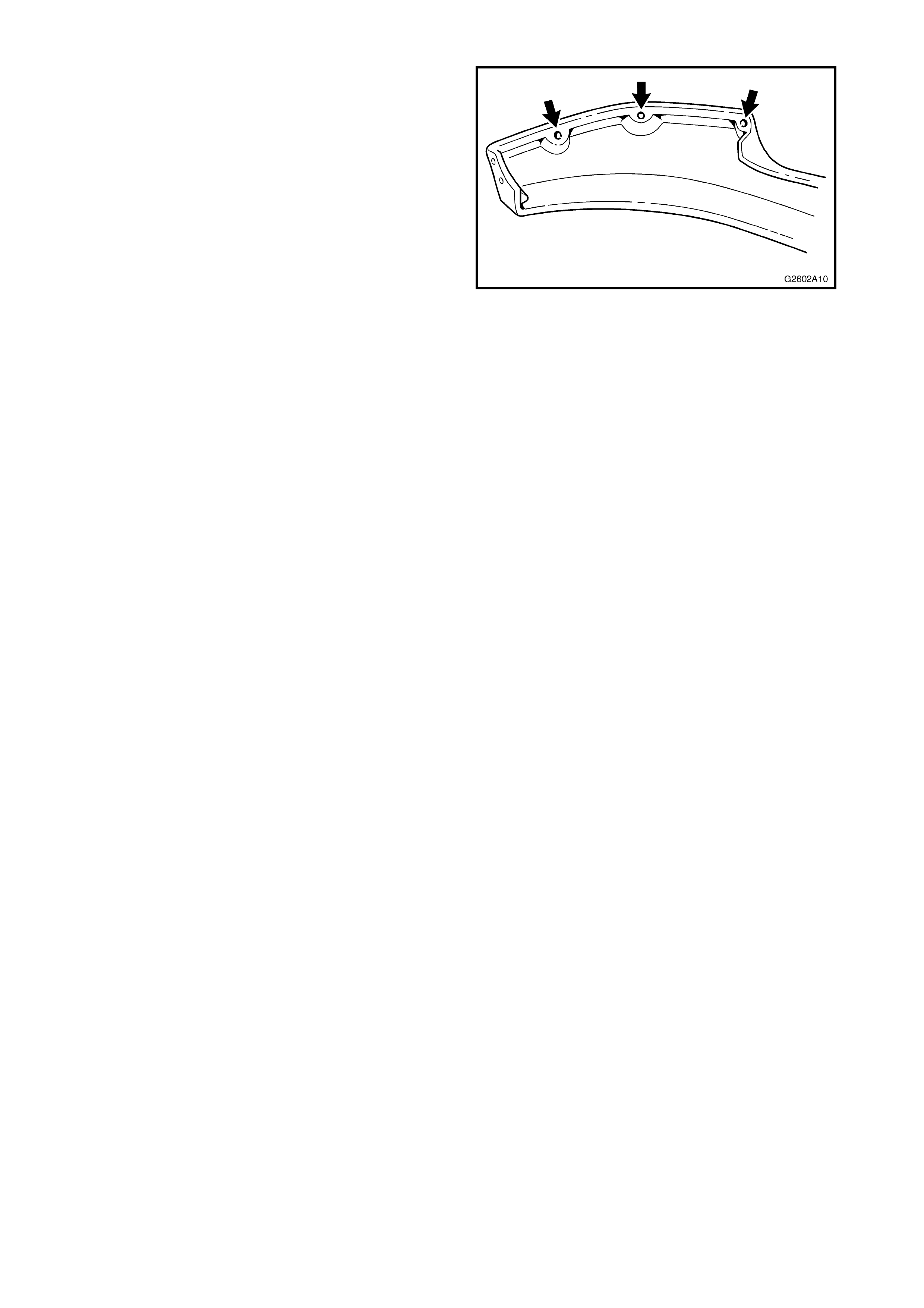
DISSASSEMBLE
1. If the bum per f ac ia is not damaged, plac e it on a
soft surface to avoid scratches.
2. Remove the six screws (1) from the inner side of
the bumper facia.
3. Remove the extension.
Figure 2A-10
INSTALL
1. Apply 3M stone chip film (1) to the front of the
extension as shown. Smooth out all trapped air
as the film is being applied.
NOTE: Ensure ar ea is clean and free of dirt, grease
and finger marks prior to affixing the film.
2. If the bumper facia has not been replaced
proceed to step 8.
Figure 2A-11
3. Place a small piece of caulking compound or
like, on the centre of each s crew hole landing as
shown.
4. Apply a daub of paint on the centre of the
caulking compound.
5. With the aid of an assistant, carefully fit the
extension in position, transferring the paint to
the bumper facia.
6. Remove the extension and compare the paint
mar ks with the bumper facia to ensure the paint
transferred correctly.
7. Drill the bumper f ac ia with scr ew holes using a 3
mm drill bit.
8. With the aid of an ass istant, place the extens ion
in its correct position.
9. Insert the screws to attach the extension to the
bumper facia.
NOTE: Adjustment may be required to ensure no
gaps exist along the top edge of the extension. If
required, apply a thin, smooth bead of Sikaflex or
equivalent along the edge.
Figure 2A-12
10. Drill the screw holes at each end of the
extension.
11. Fit the license plate light, if removed.
12. Install the bumper assembly in position,
connecting the license plate wiring connector.
13. Fit the screws attaching the bumper assembly,
16 places, refer Fig. 2A-9.
14. Refit tail lights and inner trim covers.
5. REAR SPOILER
The Holden By Design rear spoiler is mounted to the
tailgate by threaded studs which are encapsulated into
the spoiler and nuts. Fitment of the spoiler does not
interfere with the operation of the high mount stop light.
A replacement part is supplied unpainted and will
require painting prior to fitment.
The painting procedures are relatively straight forward,
providing the corr ect steps f or ref inishing PUR with rigid
structure foam core material are followed.
As materials and techniques will vary depending on the
brand of paint used, painting procedures are not
provided in this Supplement. Ref er to your paint supplier
if further information is required.
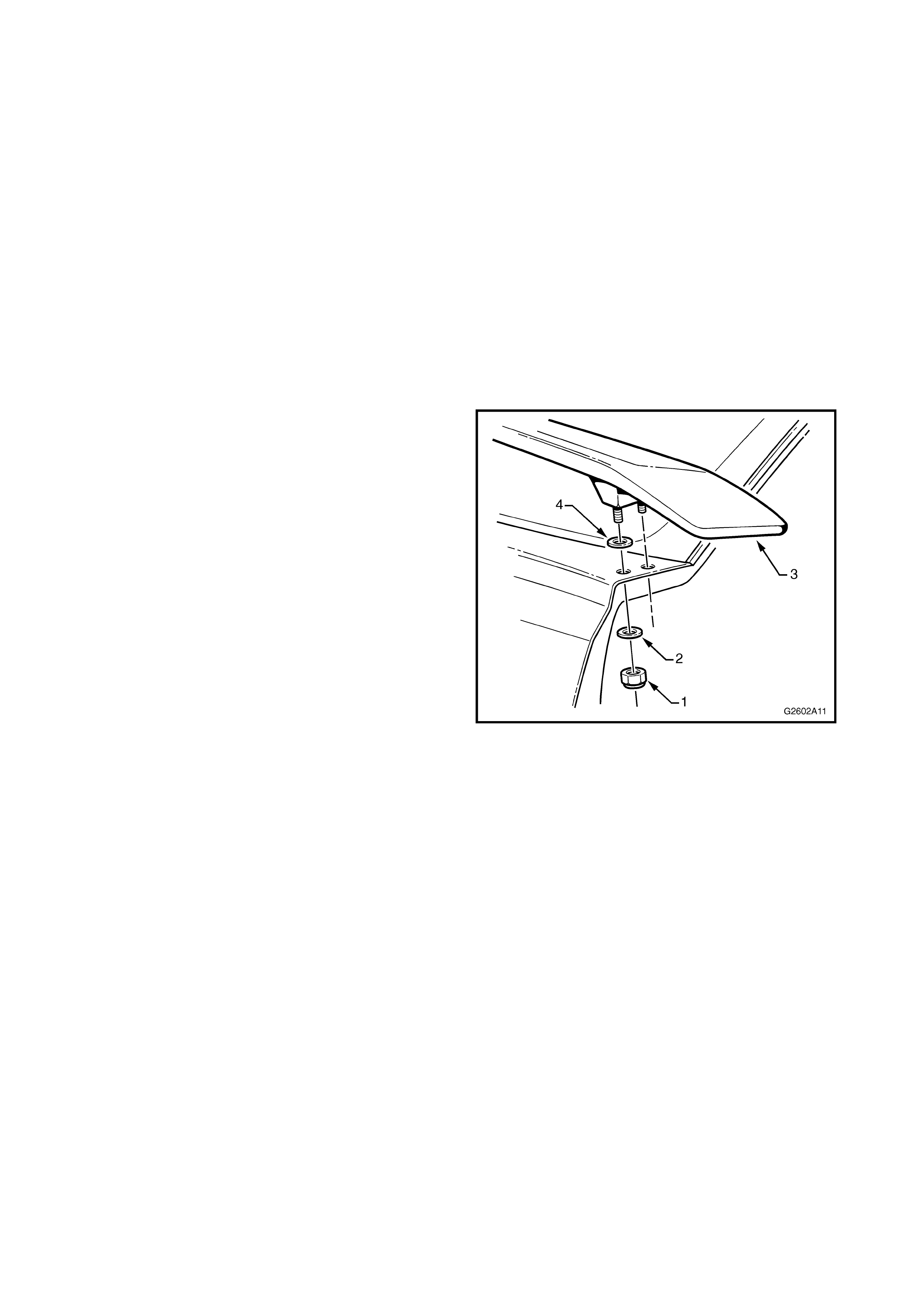
REMOVE
1. Open the tailgate and remove the two nuts (1)
and washers (2) attaching each side of the
spoiler (3) to the tailgate.
2. Remove the spoiler and ensure the seal (4)
remains with the spoiler.
Figure 2A-13
INSTALL
NOTE: If the tailgate has not been replaced,
proceed to Step 8.
1. Construct a drilling template from paper or light
card by photocopying or tracing Fig. 2A-15.
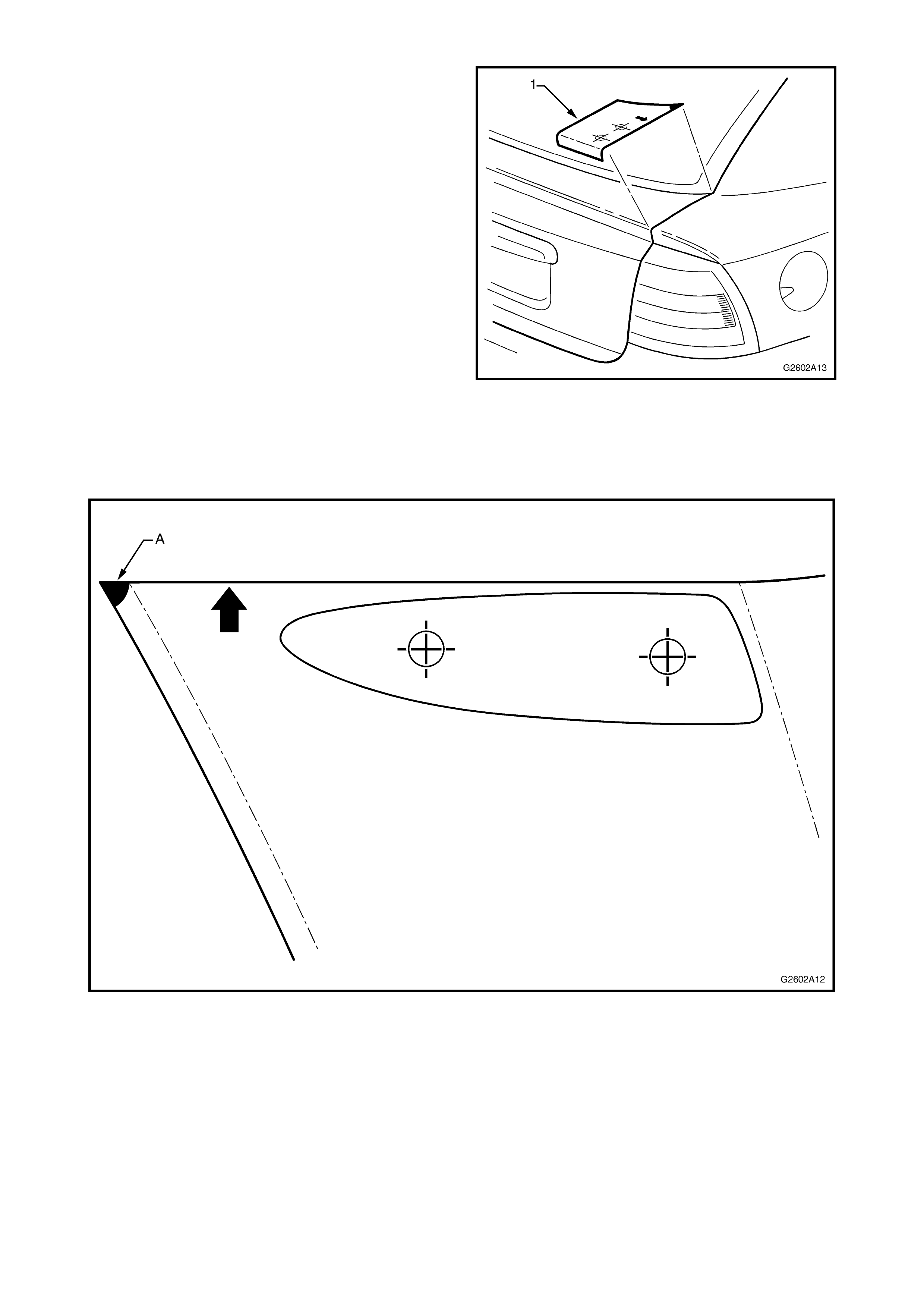
2. Place the tem plate (1) on the tailgate as shown,
ensuring the reference point (A) is aligned with
the edge of the rear windscreen moulding and
edge of the tailgate.
3. Mark the mounting hole centre points on the
tailgate.
4. Turn the template over and repeat for the other
side.
5. Sit the spoiler on the tailgate and ensure the
mounting studs align with the centre point
marks. Adjust as required.
6. Open the tailgate slightly and carefully drill 3mm
holes, followed by 8 mm holes completely
through the tailgate.
NOTE: Ensure not to drill into the water channel
below.
7. Debur the holes and apply primer to the bare
metal.
8. Ensure the seals are seated on each mounting
stud, refer Fig 2A-13.
9. Fit the spoiler to the tailgate and install the
washers and nuts and tighten.
Figure 2A-14
Figure 2A-15
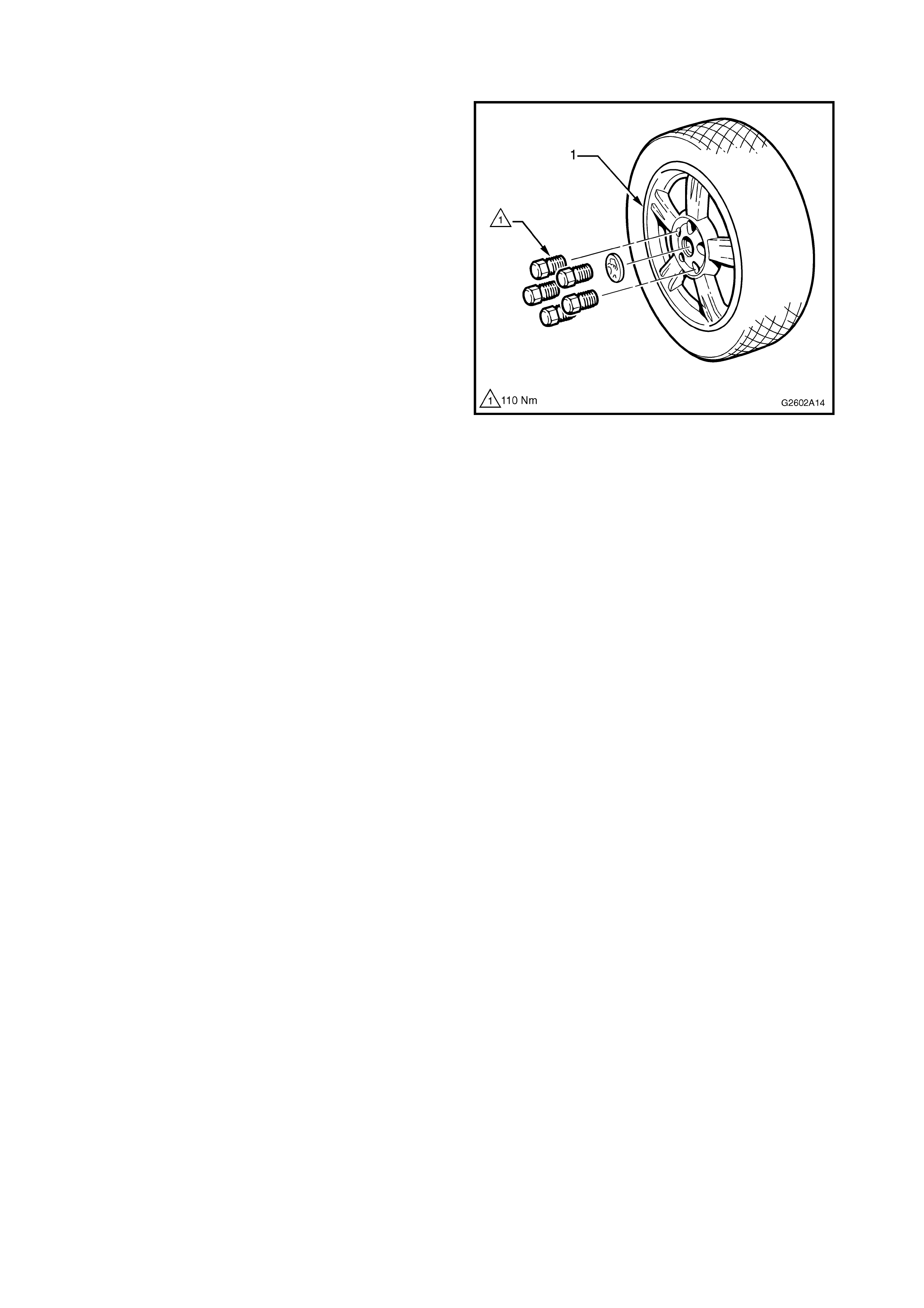
6. ALLOY WHEELS
A unique 16” x 6” five spoke alloy wheel (1) is
available for the Holden By Design TS Astra, as part
of the id package or individually.
NOTE: As with all TS Astras, four-stud rims are
fitted to non-ABS vehicles. The five-stud rim as
shown is fitted to vehicles with ABS. The design of
the rim does not change.
The alloy wheels are fitted with 205/55 R16 V-rated
Dunlop Bathurst 1000 tyres. The standard steel rim
spare wheel is retained.
NOTE: The tyres are uni-directional. Always ensure
they are fitted in the correct direction of rotation.
This Section of the Holden By Design Service
Information Supplement illustrates the wheel type
only. For the inf orm ation requir ed to servic e wheels,
refer to the Astra Service Instructions on TIS 2000.
Figure 2A-16
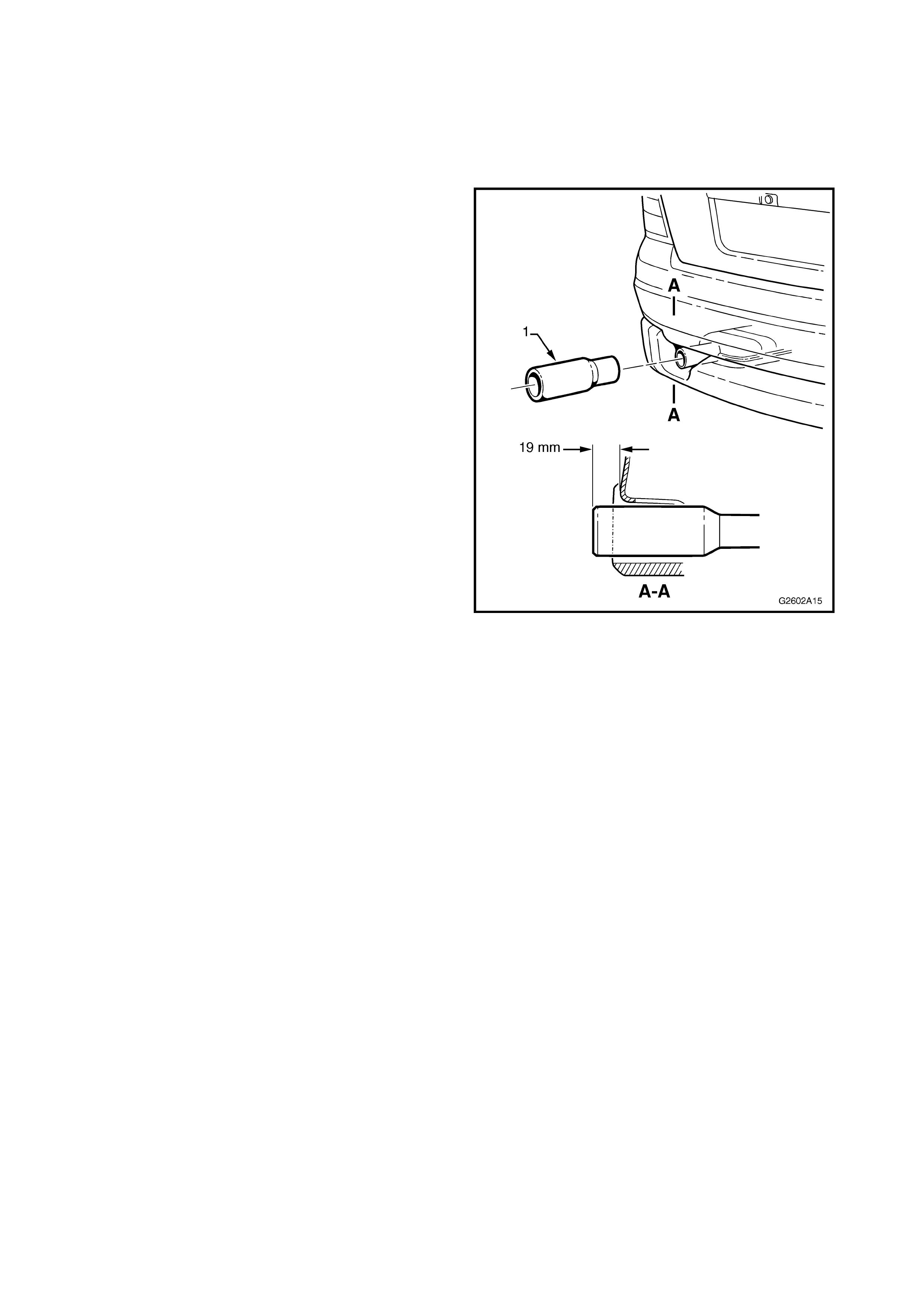
7. EXHAUST EXTENSION
A chrome plated exhaust extension is fitted as part
of the Holden By Design id package.
REMOVE
1. Using a hammer and block of wood seated
against the front edge of the extension (1),
knock the extension off the exhaust pipe.
INSTALL
1. Sit the extension on to the end of the exhaust
pipe, ensuring correct orientation.
2. Carefully knock the extension onto the exhaust
using a rubber mallet until dimension shown is
achieved.
NOTE: Cover the extension with a soft rag to
prevent damage.
Figure 2A-17

8. IDENTI FICATION & BADGING
W her e a full Holden By Design id kit has been ins talled,
a HBD identification plate, Holden By Design decals, id
emblem s and a Holden By Design emblem are fitted to
the vehicle.
Figure 2A-18 shows the location of the HBD
identification plate. The identification plate is pop-
riveted to the vehicle using the existing holes in the
radiator support panel.
Figure 2A-18
Figure 2A-19 shows the location of the id emblem and
the positioning measurements on the C-pillar.
The emblem is affixed with double-sided tape.
Figure 2A-19
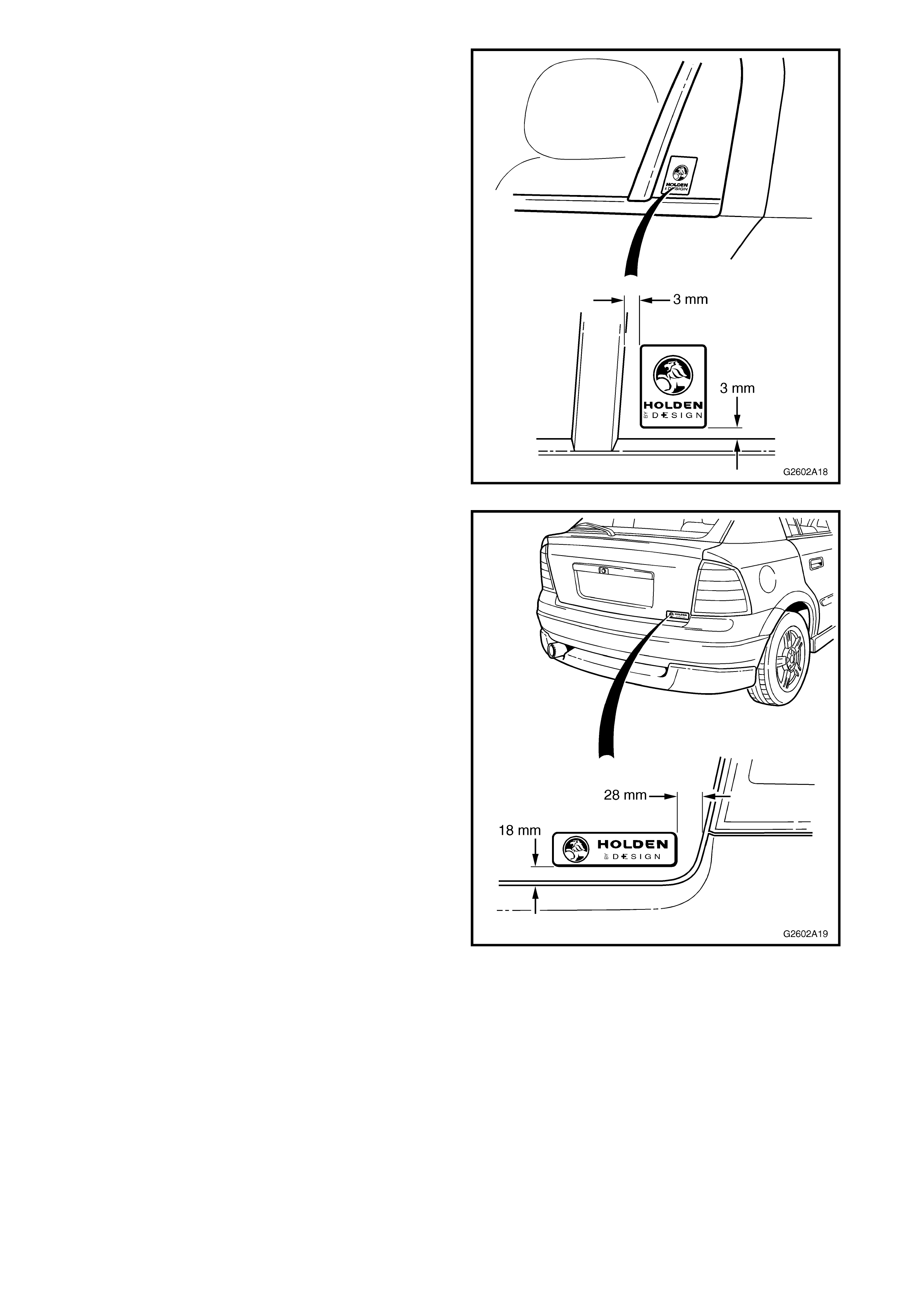
Figure 2A-20 shows the location of the Holden By
Design decal and the positioning measurements on
the rear door fixed glass.
The decal is self-adhesive.
Figure 2A-20
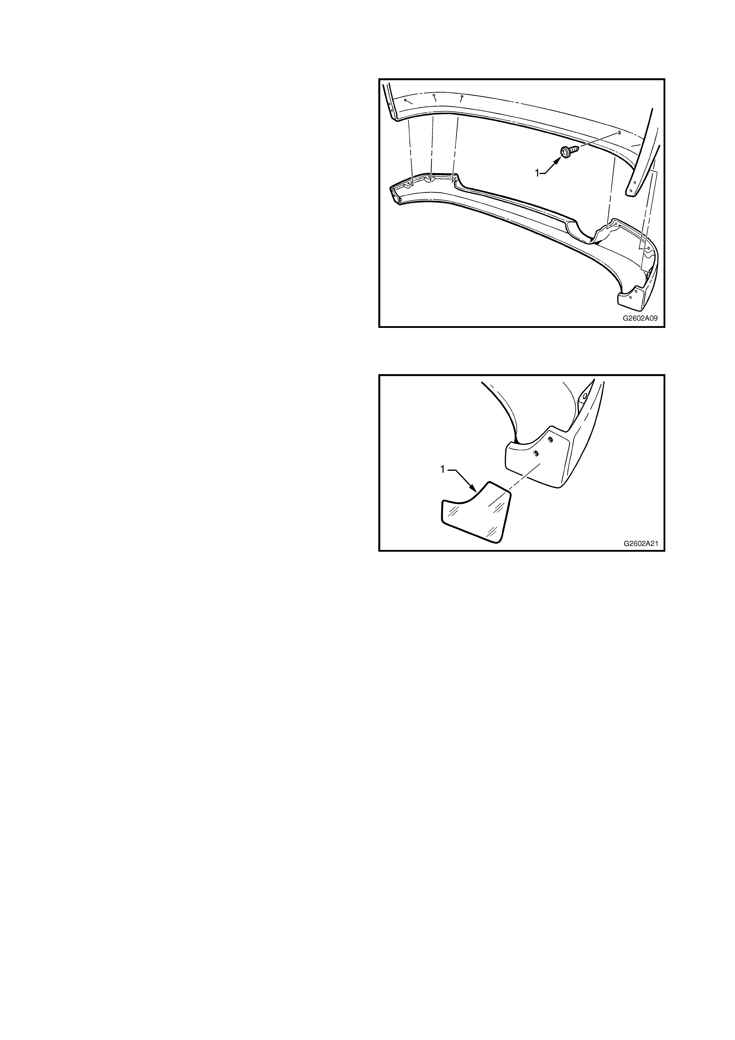
Figure 2A-21 shows the location of the Holden By
Design emblem and the positioning measurements on
the tailgate.
The emblem is affixed to the tailgate with double-
sided tape.
Figure 2A-21