
SECTION 2B - TS SERIES ASTRA BODY
KIT UPDATE
1.0 GENERAL INFORM ATION
This Section of the Holden By Design Service Information Supplement describes additional service procedures for
the ID body styling kit components available for TS Astra 3 & 5 door hatch, excluding SRi, and 4 door sedan
vehicles. It is to be used in conjunction with Section 2A, TS SERIES A STRA BODY KIT in this Service Information.
The body styling kit consists of:
• A front bumper facia which can now incorporate the fog lamps from the Astra CD model,
• The original side skirts which are modified to integrate with the styling package,
• A unique rear bumper extension,
• A rear spoiler for hatch & sedan variants,
• Alloy wheels,
• A chrome exhaust extension,
• Holden By Design badging, and
• A Holden By Design identification plate.
NOTE 1: Vehicles can be supplied with only the rear spoiler or alloy wheels. In these instances no Holden By
Design identification or badging is included.
NOTE 2: As a r unning change, the shape of the exhaus t extension has been m odified. Ser vice procedures ar e not
affected.
Figure 2B-1 illustrates the TS Astra id body kit major components and the references to their service procedures.
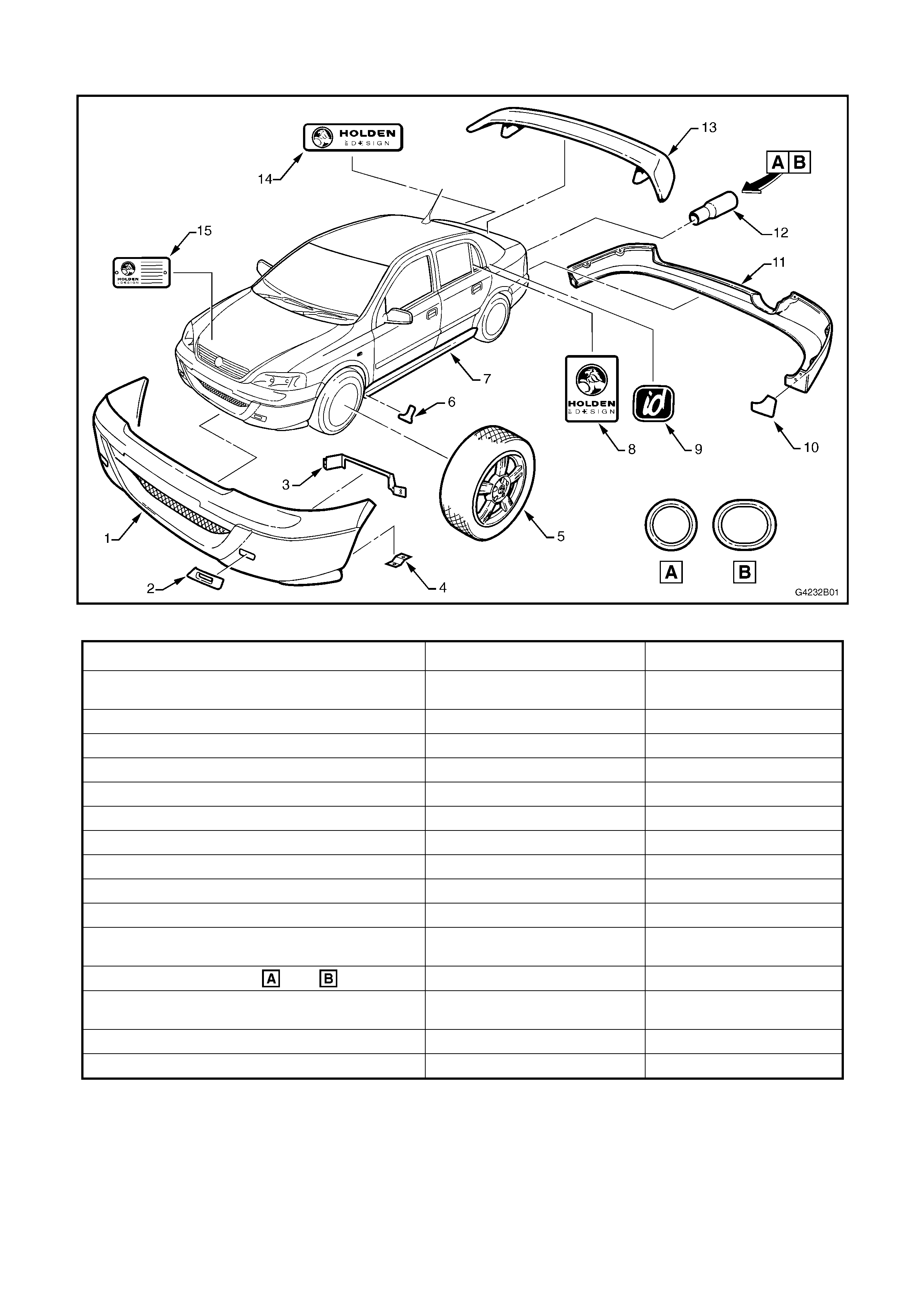
1.1 MAJOR COMPONENTS
Figure 2B-1
DESCRIPTION MODEL REFER
1. Front bumper facia – without fog lamps
– with fog lamps Hatch & Sedan
Hatch & Sedan, where fitted Section 2A
Sections 2A & 2B
2. Fog lamp bezel Hatch & Sedan, where fitted Section 2B
3. Fog lamp support - upper Hatch & Sedan, where fitted Section 2B
4. Fog lamp support - lower Hatch & Sedan, where fitted Section 2B
5. Alloy wheel Hatch & Sedan Section 2A
6. Side skirt 3M stone chip film Hatch & Sedan Section 2A
7. Side skirt (original part modified) Hatch & Sedan Section 2A
8. Holden By Design decal Hatch & Sedan Section 2A
9. id emblem Hatch & Sedan Section 2A
10. Rear bumper extension 3M stone chip film Hatch & Sedan Section 2A
11. Rear bumper extension Hatch
Sedan Section 2A
Section 2B
12. Exhaust extension – Early Late Hatch & Sedan Section 2A
13. Rear spoiler Hatch
Sedan Section 2A
Section 2B
14. Holden By Design emblem Hatch & Sedan Section 2A
15. Holden By Design identification plate Hatch & Sedan Section 2A
NOTE: Fog Lamps are not supplied with kit.
2.0 FOG LAMPS
A revised ID front bumper facia has been made available which enables the front fog lamps from the CD
model TS Astra to be fitted. This Section provides the servicing procedures for the fog lamps as fitted to
Holden By Design TS Astra vehicles. Refer to Section 2A, TS Astra Body Kit for servicing procedures of
the front bumper facia.
REMOVE
1. Remove the front bumper facia, refer
Section 2A, TS Astra Body Kit.
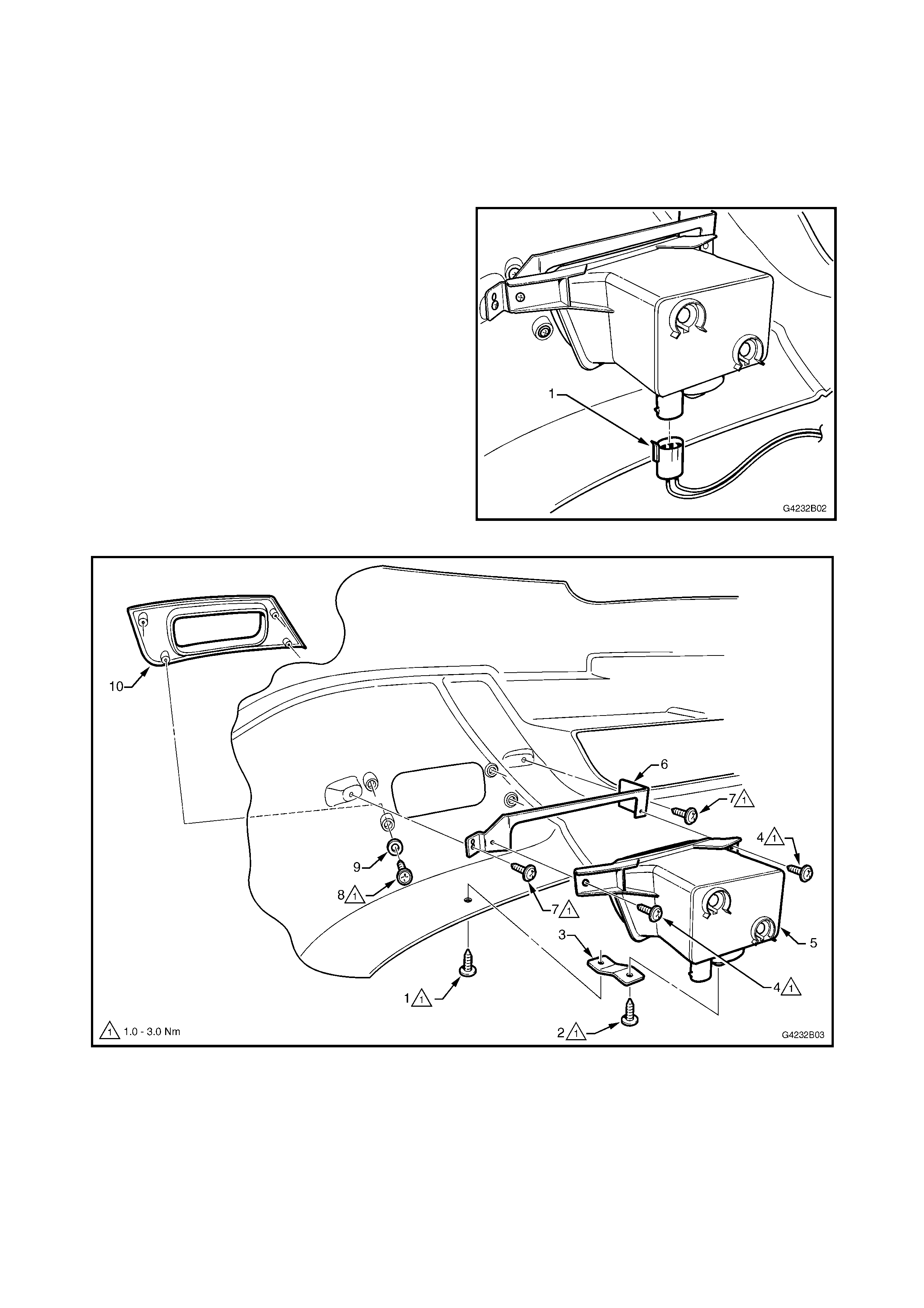
NOTE: Disconnect the fog lamp wiring connector
(1) each side prior to completely removing the
bumper facia.
2. From the rear of the bumper facia, remove the
screws (1) and (2) attaching the lower support
(3). Refer Fig. 2B-3
3. Remove the screws (4), two places, attaching
the fog lamp (5) to the upper support (6) and
remove t he lamp.
4. Remove the screws (7), two places, attaching
the upper support to the bumper facia and
remove the support.
5. Remove the screws (8) and washers (9), four
places, attaching the bezel (10) to the bumper
facia and remove the bezel.
Figure 2B-2
Figure 2B-3
FACIA MODIFICATION
Where a new facia is being fitted that requires fog
lamps, modify the facia as described below.
NOTE: If the facia is painted, protect the surface
accordingly to avoid damage.
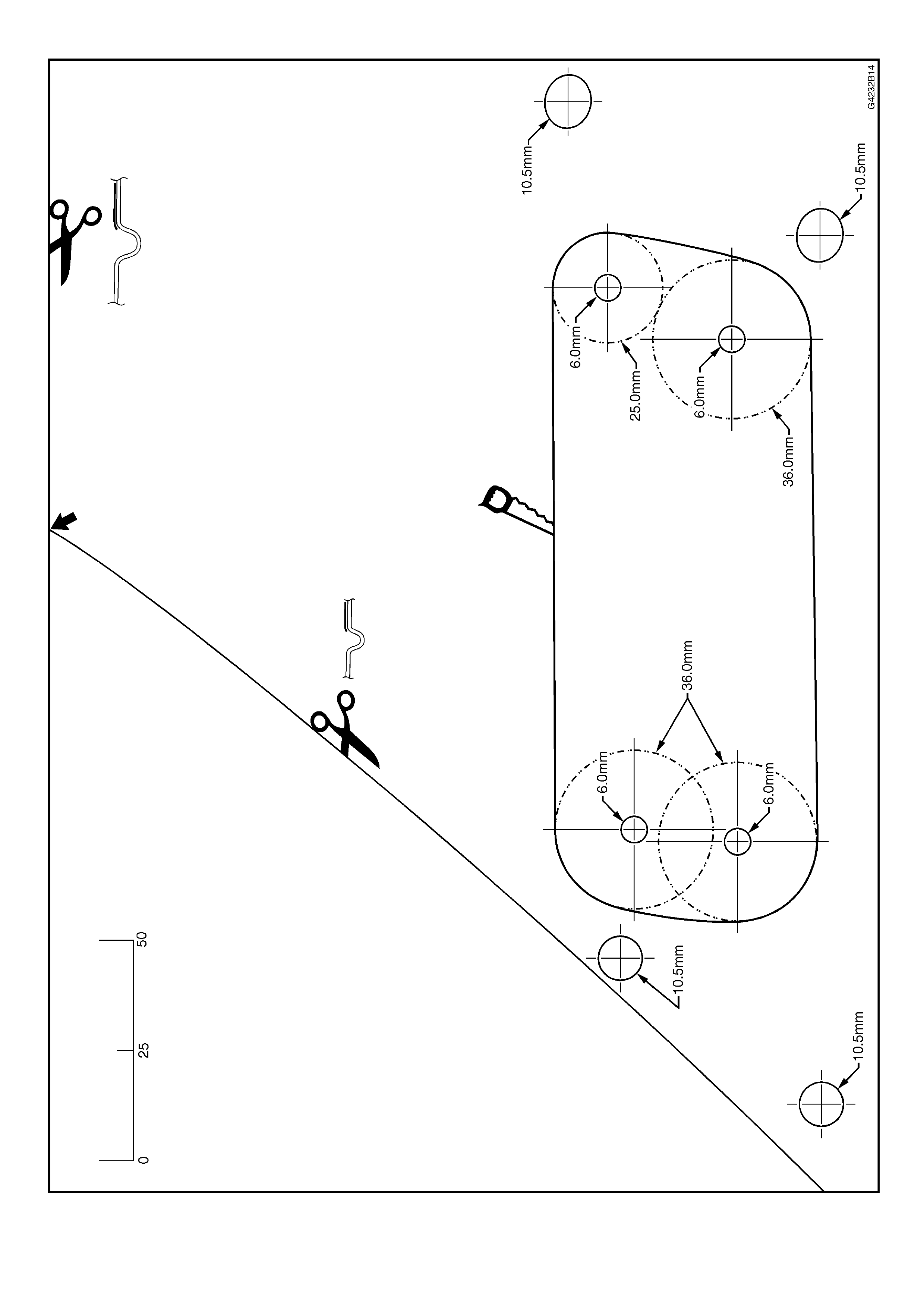
1. Print or copy the template supplied on page
2B-9.
NOTE: Ensure it is printed at the correct size.
Check by measuring the scale on the template.
2. Cut the template along the top and inner side as
marked.
3. Fix the template on to the facia with tape,
aligning the cut edges of the template with the
edges of the facia style lines as shown.
4. Mark the facia with the eight holes.
5. Remove the template.
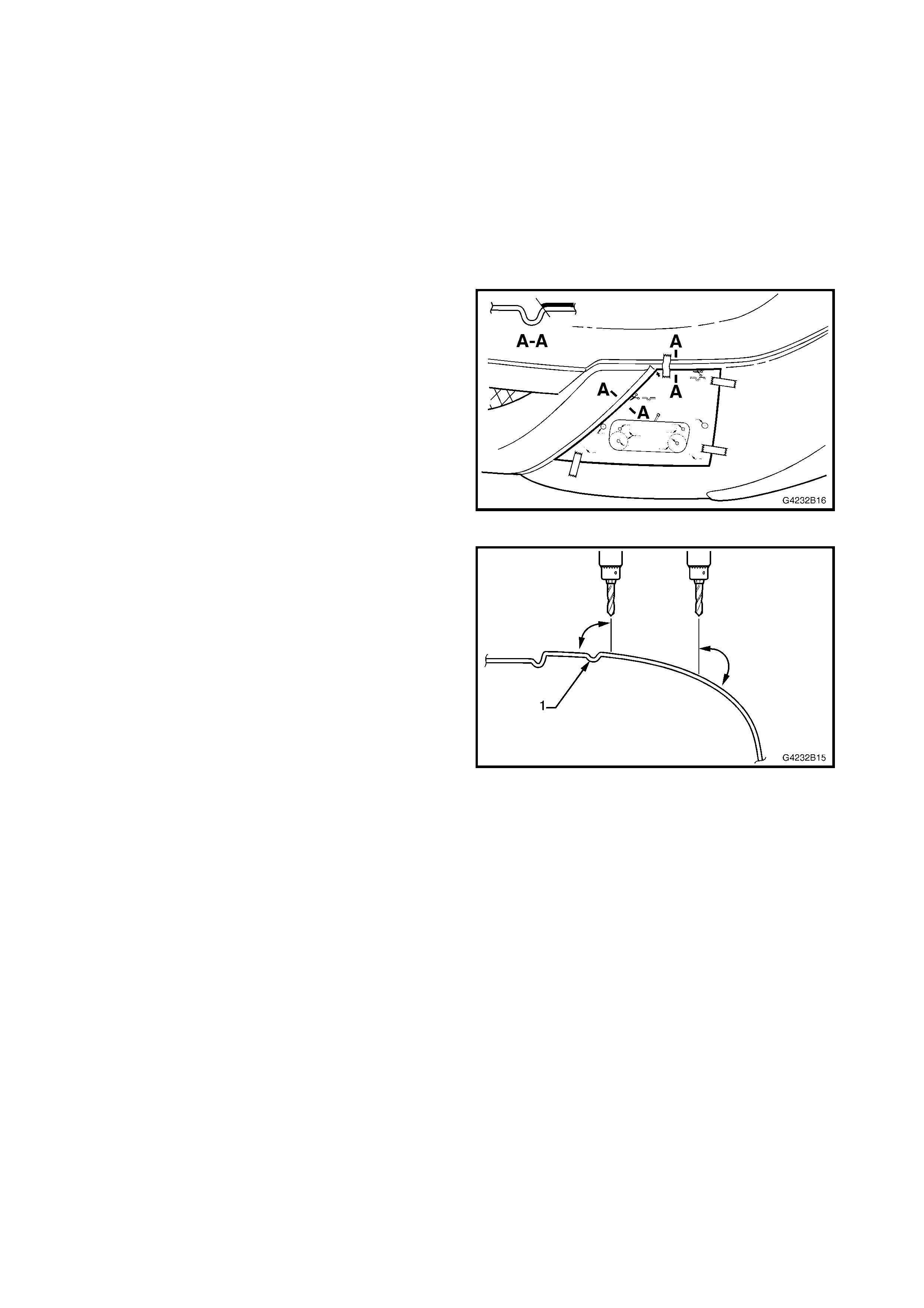
Figure 2B-4
6. Sit the facia (1) on a level surface with the front
face up.
IMPORTANT: When drilling the following holes,
hold the drill vertic ally to maintain the cor rect drilling
angle
7. For the fog lamp bezel, drill four 10.5 mm holes.
NOTE: It is important that these holes protrude the
inner side of the facia centrally in their bosses. It
may be preferable to drill a small pilot hole first.
8. For the fog lamp opening, drill four 6 mm pilot
holes.
9. Using a hole s aw, drill the upper outer pilot hole
to 25 mm.
10. Using a hole saw, drill the remaining three pilot
holes to 36 mm.
11. Cut the remaining section of facia for the fog
lamp opening between the hole saw holes.
12. Test fit the fog lam p bezel and clean-up the cut
surfaces as required.
13. Turn the template over and repeat for the
opposite side.
Figure 2B-5
INSTALL
1. Installation of the components is the reverse of
removal. Tighten the screws to the specified
torque.
NOTE 1: If required, drill holes in the rear of the
facia for the upper and lower supports by sitting the
parts in position and mar king the hole loca tions. For
the upper s upport do not dr ill c ompletely through the
facia.
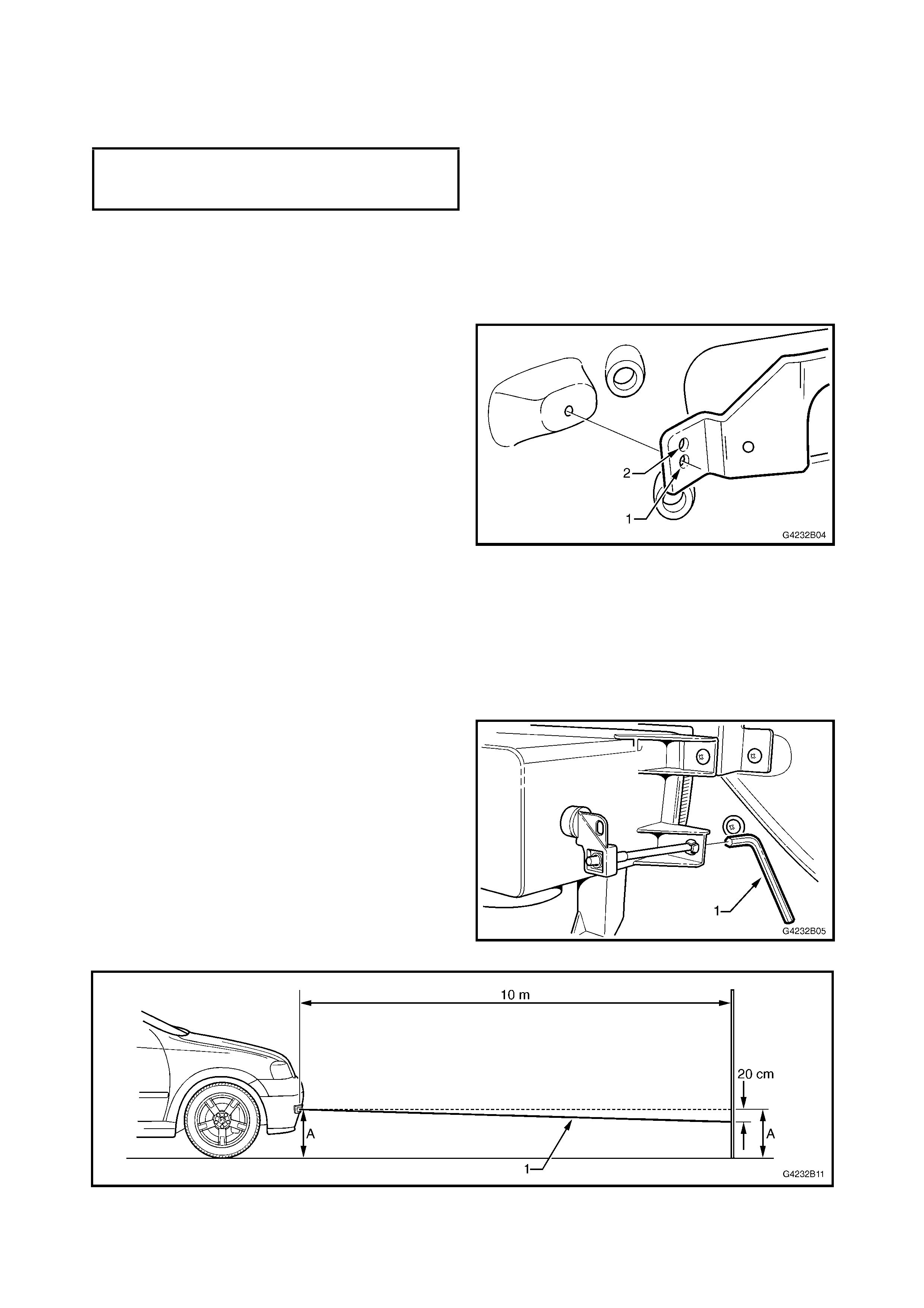
NOTE 2: When installing the upper support ensure
the correct outer hole is used, The lower hole (1) is
for the LH side and the upper hole (2) is for RH side.
2. Install the bumper facia as described in
Section 2A TS Astra Body kit.
Figure 2B-6
ADJUST
1. Adjustment of the fog lamps is to be performed
with the vehicle at kerb weight (fuel and fluids
full, tyres at correct inflation pressure, all
accessories fitted, etc.), a person seated in the
driver’s seat and the vehicle positioned on a
level surface.
2. From under the vehic le, use a 90° Allen key and
turn the adjusting screw to achieve an
inclination of the fog lam p beam (1) downwards
2% (20cm in 10m).
Figure 2B-7
Figure 2B-8
FOG LAMP ASSEMBLY
ATTACHING SCREWS 1.0 – 3.0Nm
TORQUE SPECIFICATION
3.0 REAR BUMPER EXTENSION – SEDAN
The sedan rear bumper extension is secured to the rear bumper facia with screws. Removal of the bumper
extension will necessitate rear bumper facia removal, which is identical to the hatch, refer to
4. REAR BUMPER EXTENSION in Section 2A TS Astra Body Kit.
The s edan rear bumper ex tension is painted in the vehicle’s body colour. A replacem ent part is supplied unpainted
and will require painting prior to f itment. T he painting proc edures are relatively straight forward, providing the correct
steps for refinishing PUR-RIM material are followed.
As mater ials and tec hniques will vary depending on the brand of paint used, painting pr oc edures ar e not provided in
this Supplement. Refer to your paint supplier if further information is required.
REMOVE
1. Remove the bumper facia and extension
assembly from the vehicle as described in
4. REAR BUMPER EXTENSION in Section 2A
TS Astra Body Kit.
2. If the bumper f ac ia is not damaged, plac e it on a
soft surface to avoid scratches.
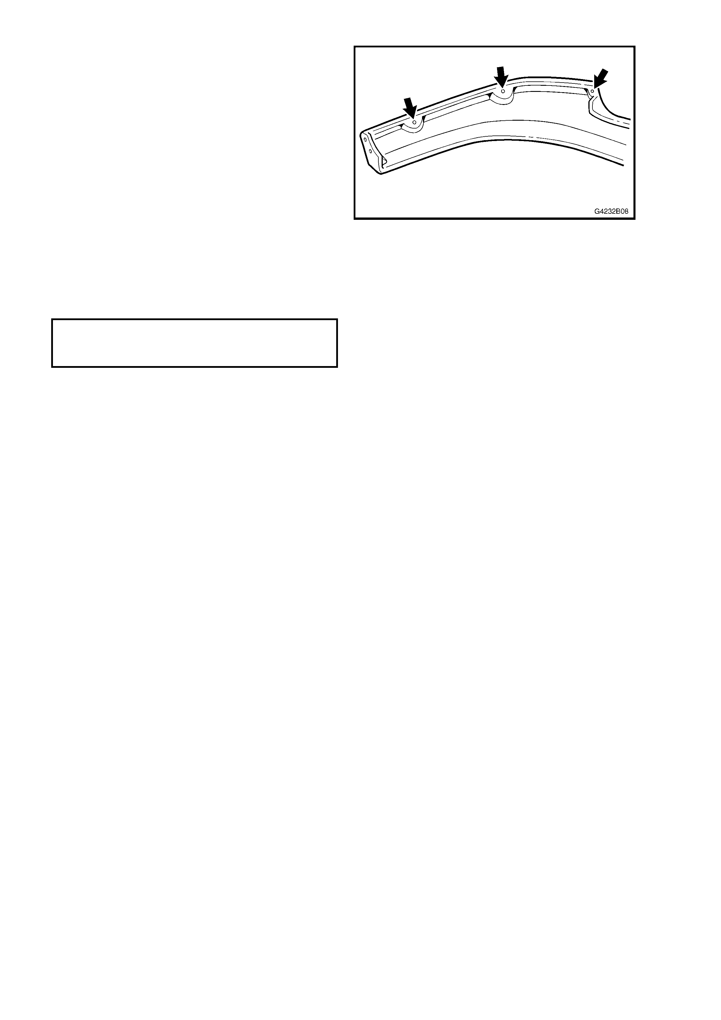
3. Remove the six screws (1) from the inner side of
the bumper facia.
4. Remove the extension.
Figure 2B-9
INSTALL
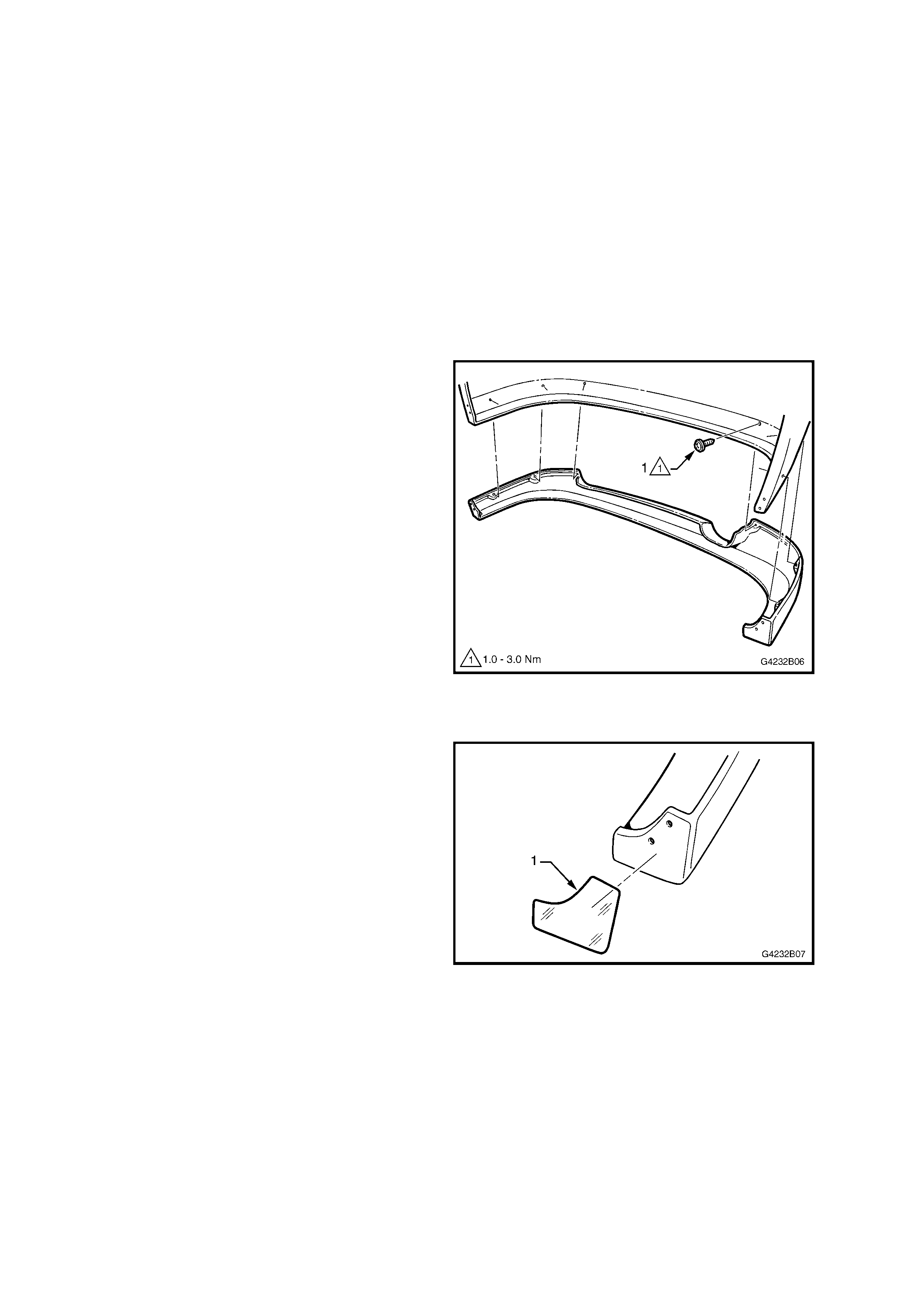
1. Following painting of the extension, apply 3M
stone chip film (1) to the front of the extension
as s hown. Sm ooth out all trapped air as the film
is being applied.
NOTE: Ens ure area is clean and fr ee of dirt, grease
and finger marks prior to affixing the film.
2. If the bumper facia has not been replaced
proceed to step 8.
Figure 2B-10
3. Place a small piece of caulking compound or
like, on the c entre of each sc rew hole landing as
shown.
4. Apply a daub of paint on the centre of the
caulking compound.
5. With the aid of an assistant, carefully fit the
extension in position, transferring the paint to
the bumper facia.
6. Remove the extension and compare the paint
mar ks with the bum per facia to ens ure the paint
transferred correctly.
7. Drill the bumper f ac ia with screw holes us ing a 3
mm drill bit.
8. With the aid of an ass istant, place the extension
in its correct position.
9. Insert the screws to attach the extension to the
bumper facia and tighten to the specified torque.
NOTE: Adjustment may be required to ensure no
gaps exist along the top edge of the extension. If
required, apply a thin, smooth bead of Sikaflex or
equivalent along the edge.
Figure 2B-11
10. Drill the screw holes at each end of the
extension.
11. Fit the license plate light, if removed.
12. Install the bumper assembly, refer
4. REAR BUMPER EXTENSION in Section 2A
TS Astra Body Kit.
REAR BUMPER EXTENSION
ATTACHING SCREWS 1.0 – 3.0Nm
TORQUE SPECIFICATION
4.0 REAR SPOILER – SEDAN
The Holden By Design s edan rear s poiler is m ounted to the dec klid by threaded studs, which ar e encapsulated into
the spoiler, and nuts. Fitment of the spoiler does not interfere with the operation of the high mount stop lamp.
A replacement part is supplied unpainted and will require painting prior to fitment. The painting procedures are
relatively straight forward, providing the c orrect s teps for r efinishing PUR with rigid structur e foam core m aterial are
followed.
As mater ials and tec hniques will vary depending on the brand of paint used, painting pr oc edures ar e not provided in
this Supplement. Refer to your paint supplier if further information is required.
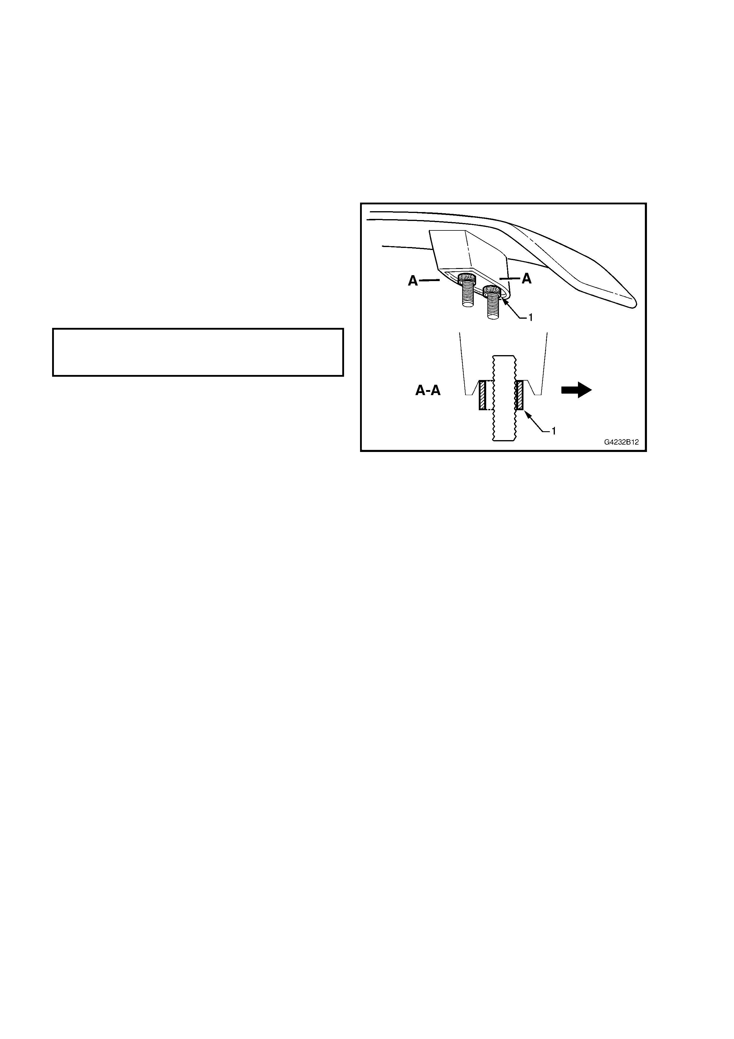
REMOVE
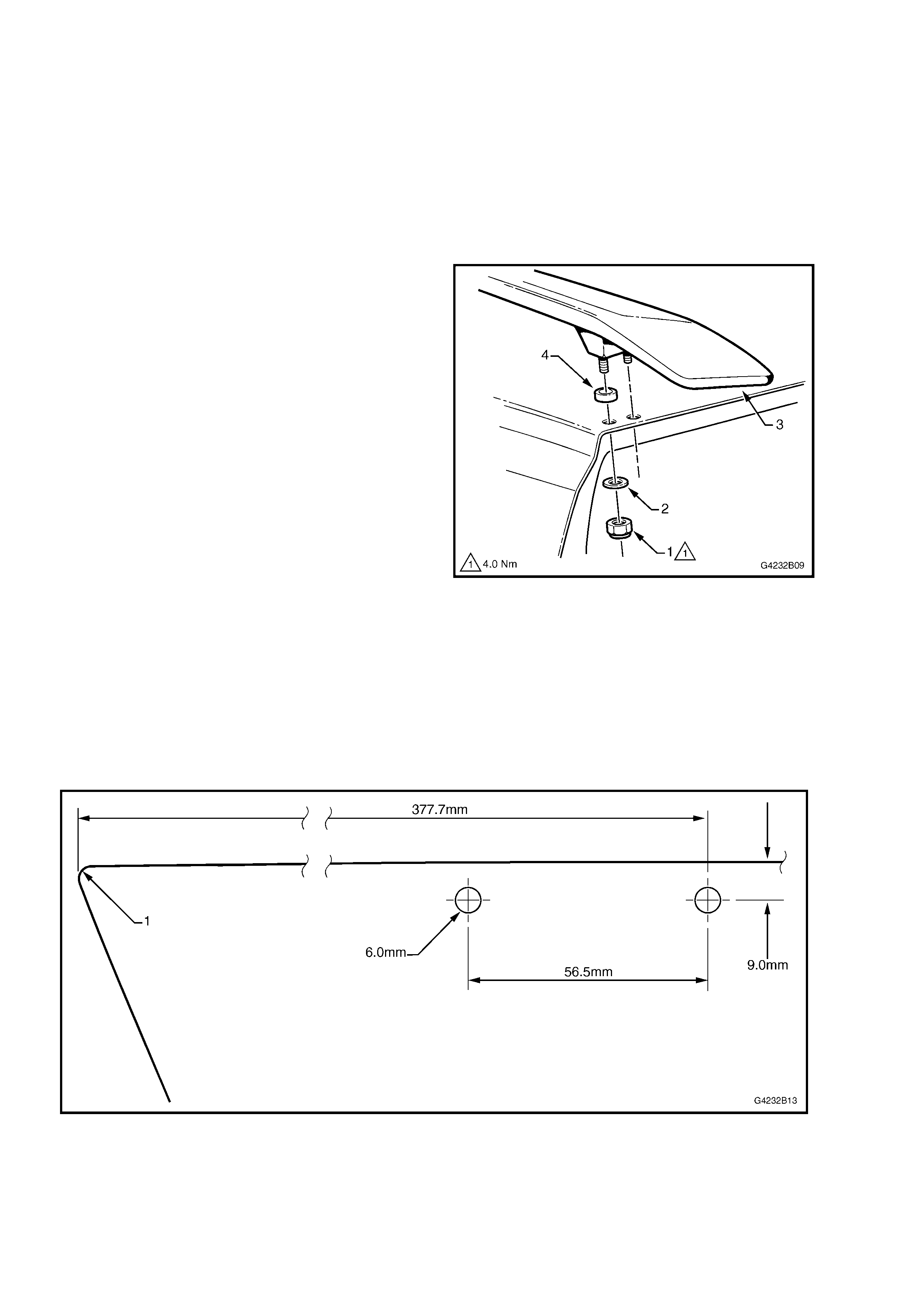
1. Open the decklid and remove the two nuts (1)
and washers (2) attaching each side of the
spoiler (3) to the tailgate.
2. Remove the spoiler and ensure the seal (4)
remains with the spoiler.
Figure 2B-12
INSTALL
NOTE: If the decklid has not been replaced,
proceed to Step 5.
1. Using the dimensions in Fig 2B-13, mark each
side of the decklid with the centre points of the
spoiler mounting holes, measuring from the front
corner (1).
NOTE: Illustration is not to scale.
Figure 2B-13
2. Sit the spoiler on the decklid and ensure the
mounting studs align with the centre point
marks. Adjust as required.
3. Open the decklid slightly and carefully drill 3mm
holes, followed by 8mm holes completely
through the decklid.
NOTE: Take care not to drill into the water channel
below.
4. Debur the holes and apply primer to the bare
metal.
5. Ensure the seals (1) are seated on each
mounting stud and that they are offset towards
the centre of the vehicle, with the outer edge
aligned against the stud. This ensures the seal
does not protrude when installed.
6. Fit the spoiler to the decklid and install the
washers and nuts and tighten to the specified
torque.
Figure 2B-14
DECKLID SPOILER
ATTACHING NUTS 4.0Nm
TORQUE SPECIFICATION

5.0 TORQUE WRENCH SPECIFICATIONS
Nm
Fog lamp assembly attaching screws.........................................................................................1.0 – 3.0
Rear bumper extension attaching screws...................................................................................1.0 – 3.0
Decklid spoiler attaching nuts......................................................................................................4.0