SECTION 3A - JR & JS SERIES VECTRA BODY KITS
1. GENERAL INFORM ATION
This Section of the Holden By Design Service Infor mation Supplem ent describes the rem oval and installation of
the aerodynamic id body styling kit components available for JR & JS Vectra Series Vehicles.
The id body styling kit consists of a front spoiler, side skirts and unique rear spoilers for Sedan and Hatch
variants. The rear spoilers include an integral LED type high mount stop lamp.
Alloy wheels, id badging and a Holden By Design identification plate are also included as part of the package.
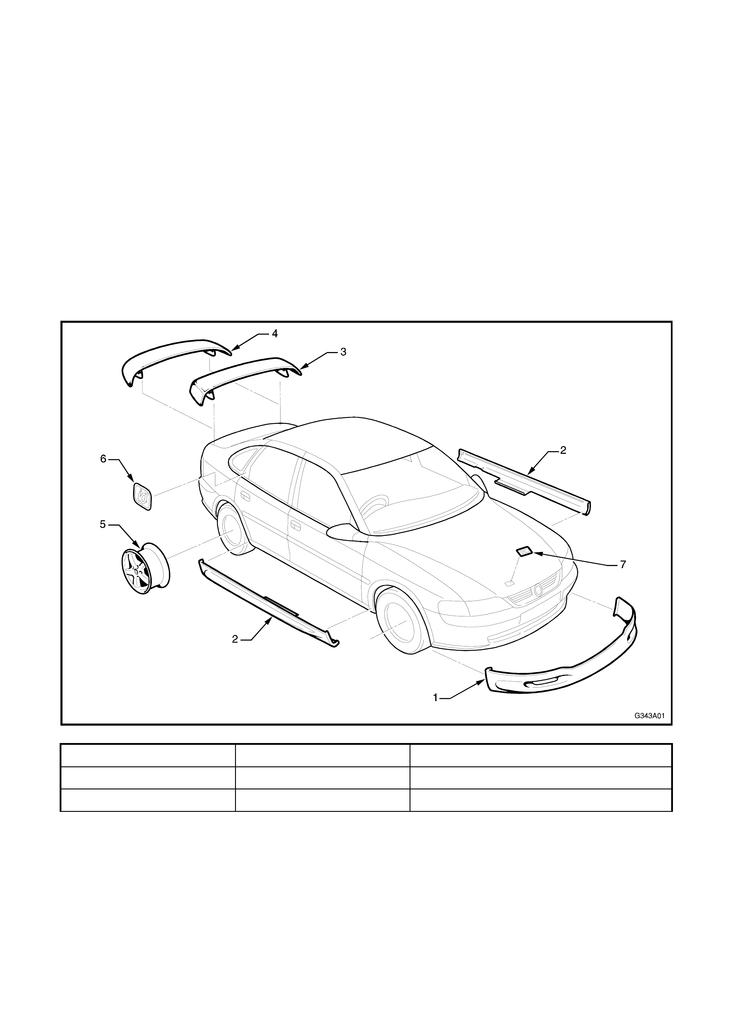
Figure 3A-1 illustrates the Vectra id body kit major components.
NOTE: Vehicles can be supplied with only one or several of the c omponents. In this c ase no Holden By Design
identification or badging is included.
For inf orm ation not contained in this Supplem ent, ref er to Gr oup A in Volum e 1 of the J R Series Service Manual
or TIS CD-ROM, Vectra B.
1.1 MAJOR COMPONENTS
Figure 3A-1
1. Front spoiler 4. Rear spoiler - Hatch 7. Holden By Design identification plate
2. Side skirts 5. Alloy wheel
3. Rear spoiler - Sedan 6. id emblem
2. FRONT SPOILER
The front spoiler is attached to the bumper facia with
adhesive, retainers and screws.
Front bumper facia removal is not required for front
spoiler removal and installation.
NOTE: T he front spoiler is painted in the vehicle’s body
colour. The painting procedures are relatively straight
forward providing the correct steps for refinishing PUR-
RIM material are followed. Refer to your paint supplier if
further information is required.
REMOVE
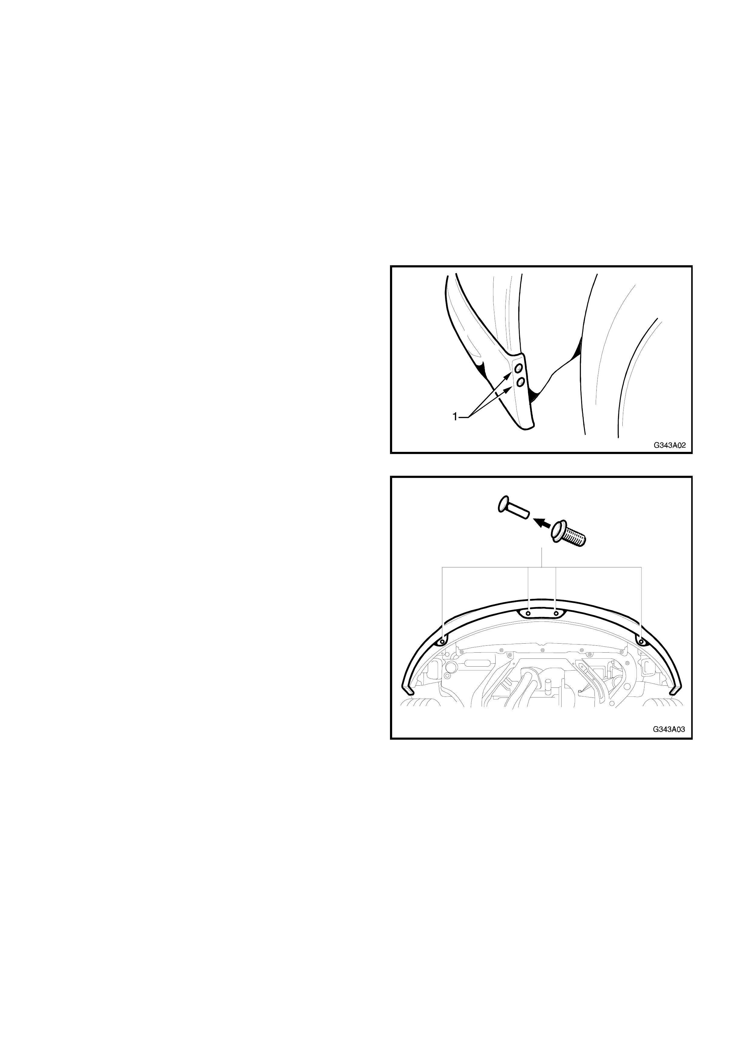
1. Remove the s crews (1) attac hing each end of the
spoiler to the bumper facia at the wheel arch
openings.
Figure 3A-2
2. From underneath the spoiler, remove the four
retainers attaching the spoiler to the bum per fac ia
by removing the centre pin from the retainer.
NOTE: The f ront spoiler m ay be attached with s crivets
as shown in Fig. 3A-3 or self tapping screws.
Figure 3A-3
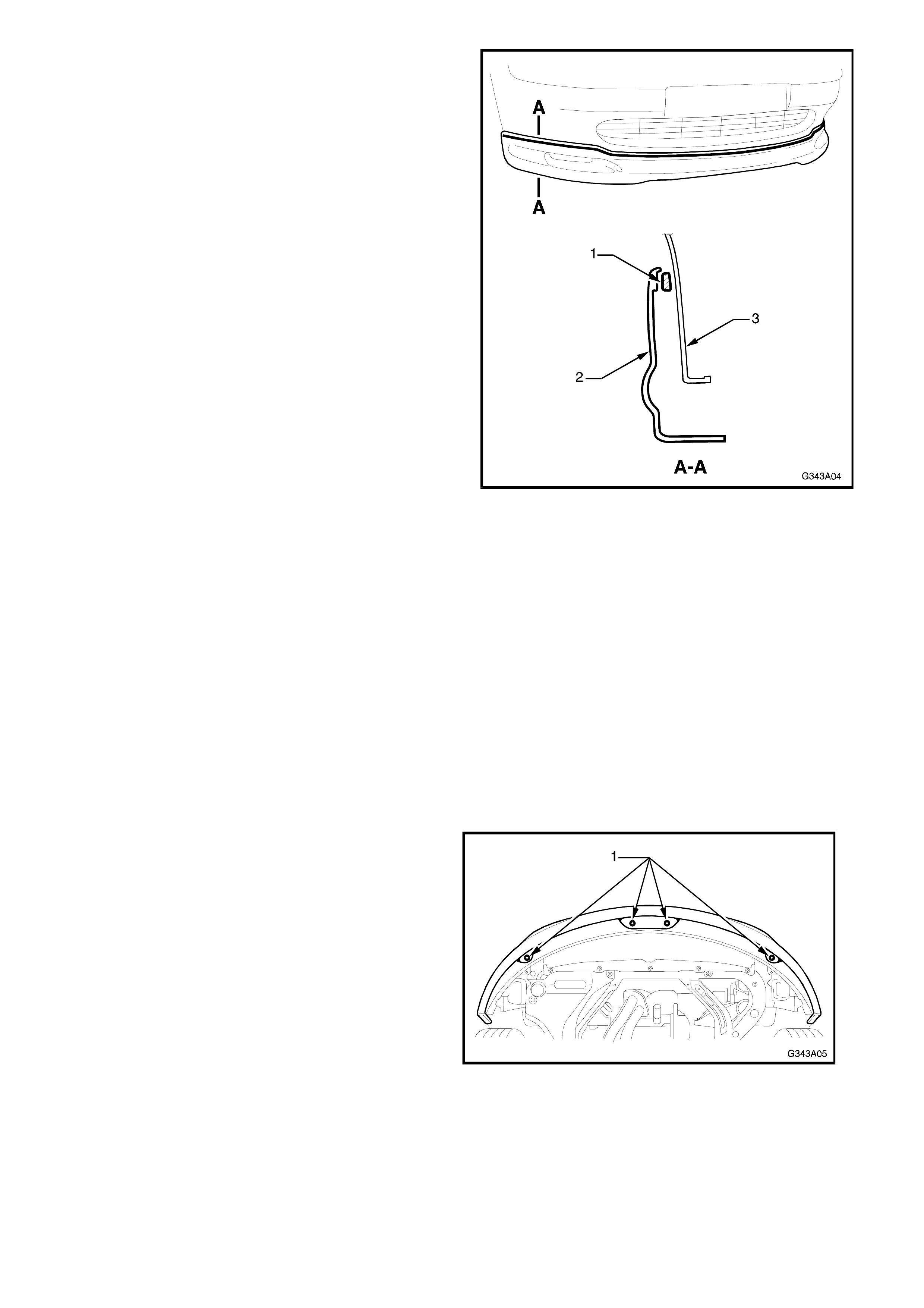
3. Using a sharp knife, cut the adhesive (1) from
behind the upper edge of the spoiler (2). This may
be made easier by applying gentle force to the
spoiler while cutting, pulling it away from the facia
(3).
NOTE: Take care not to cut into the bumper facia.
4. Remove spoiler.
5. If the bumper facia will not be replaced, clean off
the remaining adhesive.
Figure 3A-4
INSTALL
NOTE 1: The vehic le m ust not be dr iven for at least five
hours, or washed for at least 24 hours after installation
to allow the adhesive to cure. Refer to the directions
supplied with the adhesive.
NOTE 2: If the bumper facia has not been replaced,
proceed to Step 5.
NOTE 3: If scrivets were used to attach the spoiler in
the positions shown in Fig. 3A-5, dis card these and use
self tapping screws when installing the spoiler.
1. With the aid of an assistant, temporarily fit the
spoiler to the bumper facia ensuring correct
alignment.
2. From underneath, drill through the spoiler and
bumper facia with the four spoiler retainer holes
(1) with a 3 mm drill bit.
Figure 3A-5
3. Remove the spoiler.
4. W here the adhesive is to be applied, remove all
paint and primer from the spoiler and clean the
bumper facia and spoiler with the correct
urethane adhesive cleaner.
NOTE: Refer to the directions supplied with the
adhesive for further information.
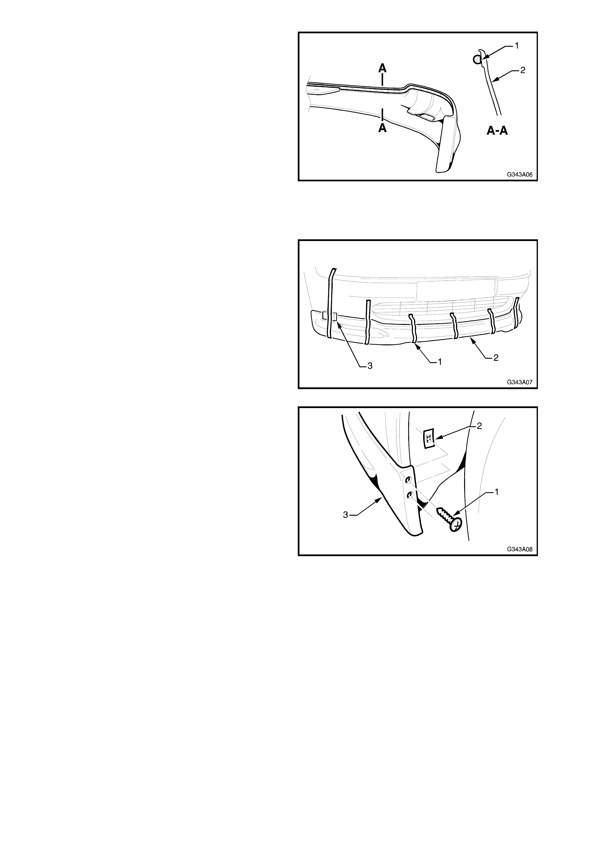
6. Apply a bead of urethane adhesive (1) such as
Betalink K1 or equivalent to the spoiler (2) as
shown in Fig. 3A-6.
NOTE: Directions enclosed with the adhesive must
be fully read and followed.
Figure 3A-6
7. Carefully fit the spoiler to the bumper facia.
8. Install four self tapping screws in the positions
shown in Fig. 3A-5.
9. Attach several lengths of mas king tape ( 1) along
the spoiler (2) to temporarily hold it in position.
Blocks (3) placed under the tape against the
upper edge of the s poiler m ay aid in achieving a
flush fit of the upper surface.
NOTE: The masking tape should not be removed
until the adhesive has cured.
Figure 3A-7
10. Drill two screw holes at each end of the spoiler,
through the bumper facia, at each wheel arch
opening with a 4 mm drill bit. Install the screws
(1) with speed nuts (2) behind at each end of the
spoiler (3) in the wheel arch opening.
Figure 3A-8
3. SIDE SKIRTS
The Holden By Design side skirt assemblies are
mounted to the existing sill panel.
A length of aluminium angle is attached to the sill with
screws and is used to support the upper surface of the
skirt. Two beads of adhesive and four clips secure the
side skirt to the sill panel.
NOTE: The side skirts are painted in the vehicle’s body
colour. The painting procedures are relatively straight
forward providing the correct steps for refinishing PUR-
RIM material are followed. Refer to your paint supplier if
further information is required.
REMOVE
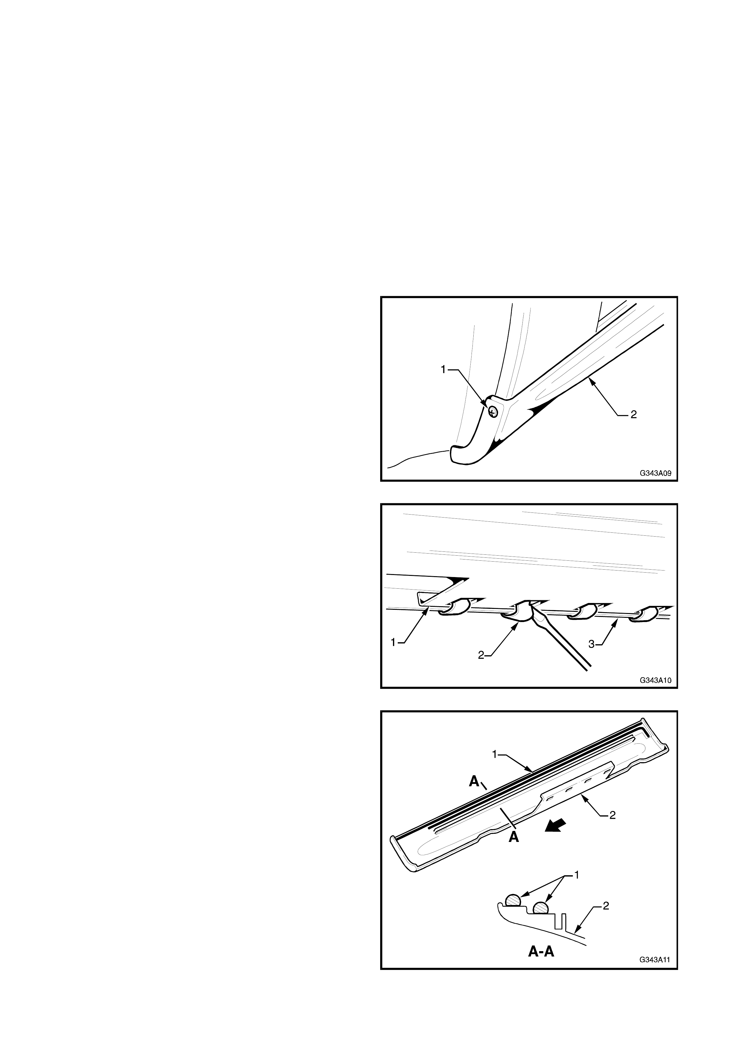
1. Remove the screw (1) attaching the front edge
of the skirt (2) to the front guard wheel arch
opening.
Figure 3A-9
2. From underneath the skir t (1), us e a scr ewdriver
to rem ove the four clips (2) attac hing the s kirt to
the sill panel (3).
Figure 3A-10
3. Starting at the front, use a sharp k nife to cut the
beads of adhesive (1) from behind the upper
and rear edges of the skirt (2). This may be
made eas ier by applying gentle f orce to the sk irt
while cutting, pulling it away from the sill.
Figure 3A-11
4. Remove the skirt.
5. If required, remove the nine screws attaching
the aluminium angle to the sill panel.
6. Using a screwdriver, gently prise the nine screw
plugs from the sill panel.
7. If the sill panel is not to be replaced, clean off
the excess adhesive.
INSTALL
N
O
TE
1
: The vehicle m ust not be driven or washed
f
or at least
f
ive hours a
f
ter installation to allow the
adhesive to cure. Re
f
er to the directions su
pp
lied
with the adhesive.
NOTE 2: If the aluminium angle was not removed,
proceed to Step 13.
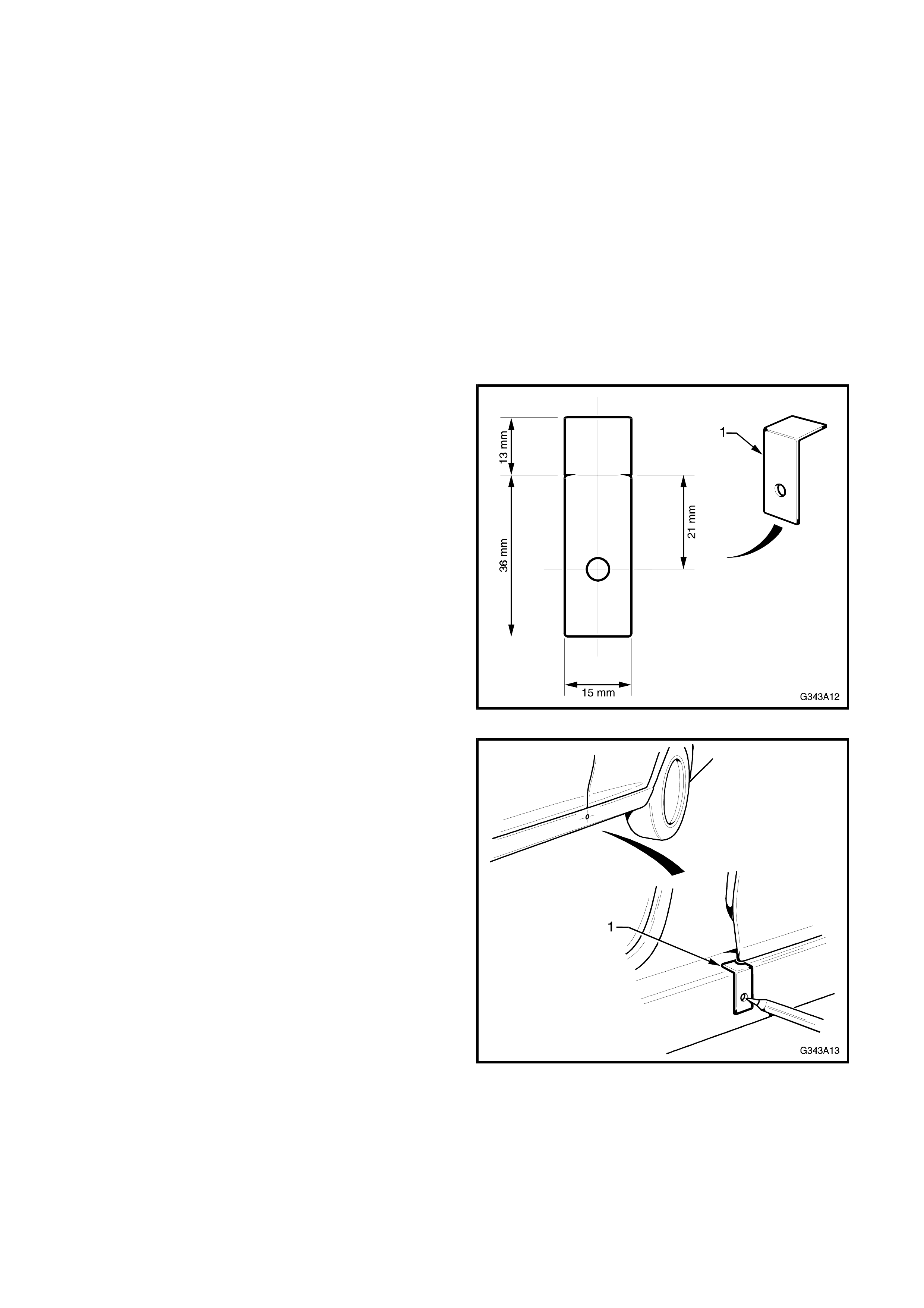
1. Construct a drilling template from light card
using the dimensions shown in Fig. 3A-12.
Figure 3A-12
2. Place the template (1) on the sill in alignment
with the door gap between the front and rear
doors, as shown in Fig. 3A-13. Mark the hole.
Figure 3A-13
3. Drill a 5 m m hole into the s ill panel and coat the
bare metal with primer.
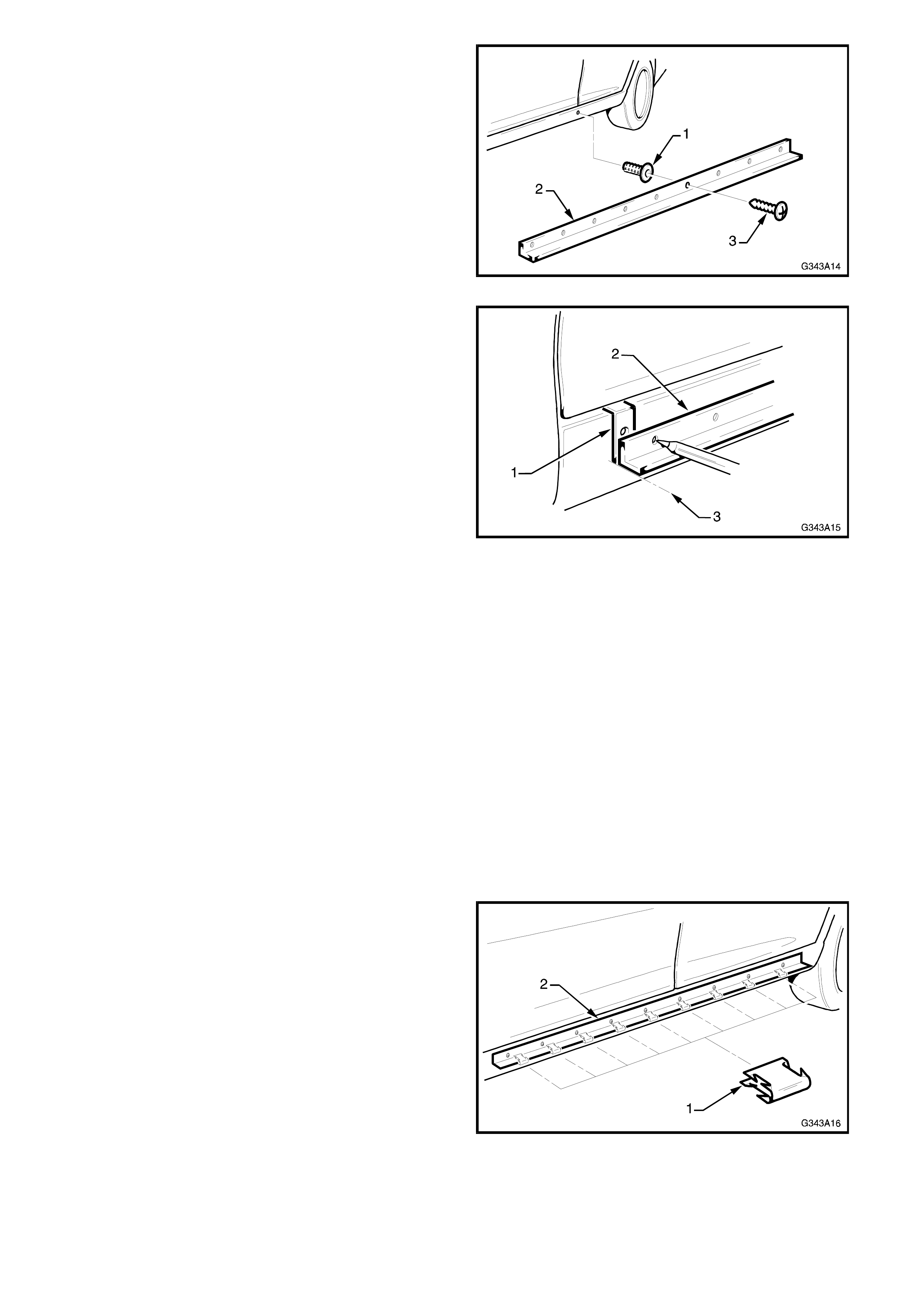
4. Insert a screw plug (1) and temporarily install the
aluminium angle (2). Ensure the screw (3) is
placed in the fourth hole from the rear of the
angle.
Figure 3A-14
5. U sing the drilling tem plate (1), place it on the sill
and align the front lower corner of the angle (2)
with the front lower corner of the template as
shown (3) in Fig. 3A-15. Mark the front hole in
the angle.
Figure 3A-15
6. Repeat Step 4 at the rear, aligning the rear
lower corner of the angle with the rear lower
corner of the template. Mark the rear hole in the
angle.
NOTE: The angle should be straight with no undue
force required to align the front and rear points.
7. Drill a 5 mm hole at the front and rear marks
and coat the bare metal with primer.
8. Ins ert a scr ew plug in each hole and tem porarily
install the front and rear screws through
aluminium angle.
9. Mark the r emaining six s crew holes and rem ove
the aluminium angle.
10. Drill the remaining holes and coat the bare metal
with primer.
11. Insert the screw plugs in the remaining holes
and install the aluminium angle.
12. Place the nine clips (1) evenly spaced onto the
aluminium angle (2) as shown in Fig. 3A-16.
Figure 3A-16
13. W here the adhesive is to be applied, remove all
paint and primer from the side skirt and clean
the sill panel and side skirt with the correct
urethane adhesive cleaner.

NOTE: Refer to the directions supplied with the
adhesive for further information.
14. Apply two beads of urethane adhesive such as
Betalink K1 or equivalent to the area shown in
Fig. 3A-11.
NOTE: Directions enclosed with the adhesive must
be fully read and followed.
15. Install the side skirt, ensuring the aluminium
angle is correctly located within the slot in the
side skirt. Tap it home with an open hand.
NOTE: At this point it may be advisable to secure
the skirt with tape, clean off any excess adhesive,
then continue when the adhesive has cured, as
continuing may open a gap along the upper edge of
the skirt. Blocks placed under the tape against the
upper edge will assist in achieving a flush fit.
16. Install the four clips attaching the side skirt to
the sill panel as shown in Fig. 3A-10.
17. Drill a 2.5 mm hole thr ough the front edge of the
side skirt and the wheel arch opening of the
front guard. Refer Fig 3A-9.
18. Prime the bare metal and install the screw.
4. REAR SPOILER
The Holden By Design Vectra Series rear spoilers are
unique for sedan and hatch variants.
Each spoiler inc ludes a LED type high m ount stop lam p
that replaces the operation of the standard high mount
stop lamp.
Removal and installation procedures differ for each
variant.
NOTE 1: If a new spoiler kit is supplied, several
electrical items are included which are not used by
HBD.
NOTE 2: The rear spoiler is painted in the vehicle’s
body colour. The painting procedures are relatively
straight forward providing the correct steps for
refinishing PU-Hard material are followed. Refer your
paint supplier if further information is required.
4.1 SEDAN
NOTE 1: W here a deck lid spoiler is fitted, the deck lid
assist s prings are upgr aded to compens ate f or the ex tra
weight. This must be taken into consideration if
replacing the springs.
NOTE 2: T he r ear hook on eac h spr ing is to be ins talled
into the rearmost hole.
REMOVE
1. O pen the deck lid and remove the dec k lid inner
trim if fitted. Refer Group A, in the JR Series
Service Manual or TIS CD-ROM.
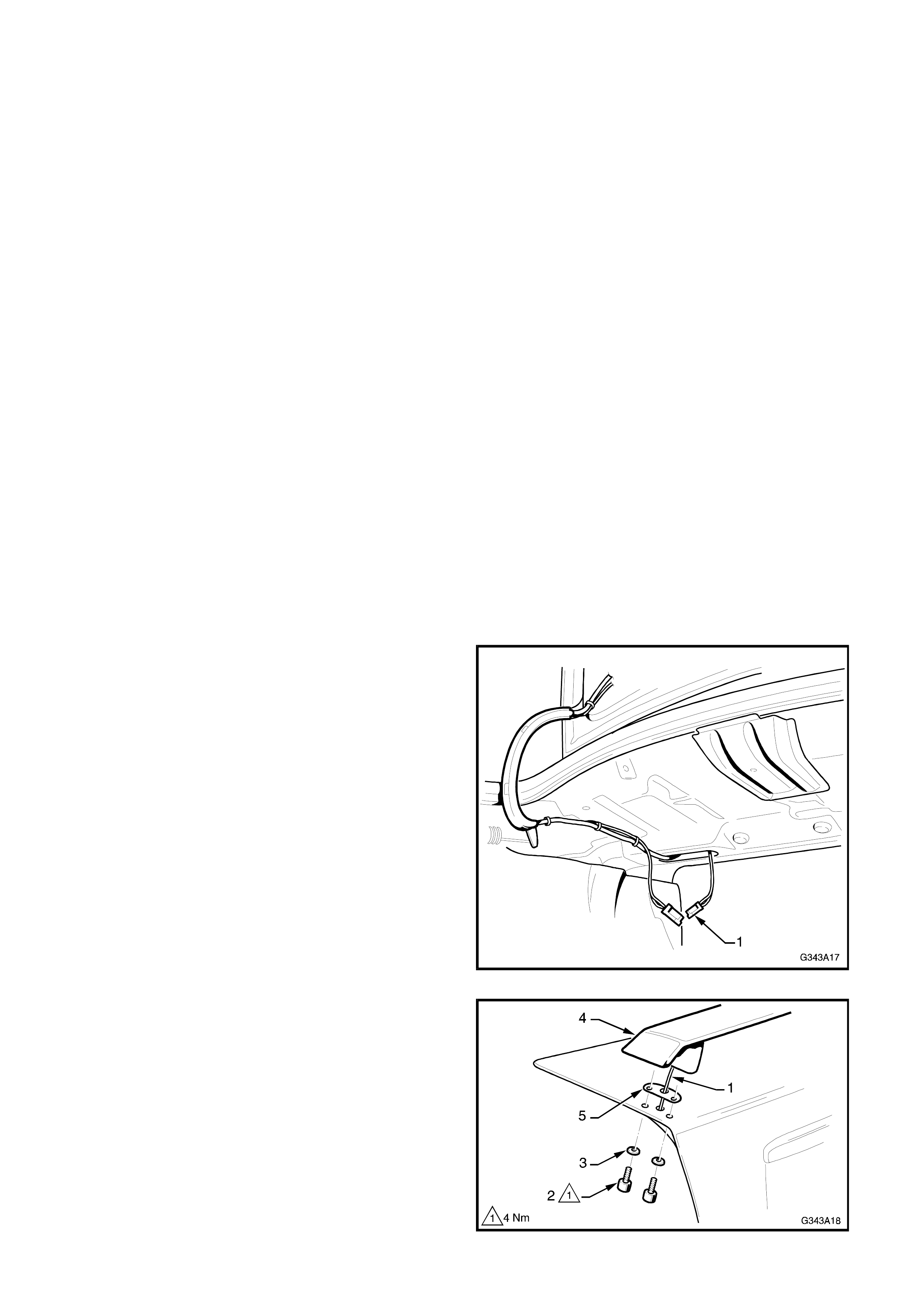
2. Disconnect the high mount stop lamp wiring
connector (1) from under the parcel shelf.
Figure 3A-17
3. Unclip the high mount stop lamp harness (1)
and pass it through the deck lid inner frame.
4. Remove the two screws (2) and washers (3)
each side attaching the rear spoiler (4) to the
deck lid. Remove the spoiler and seal (5).
Figure 3A-18
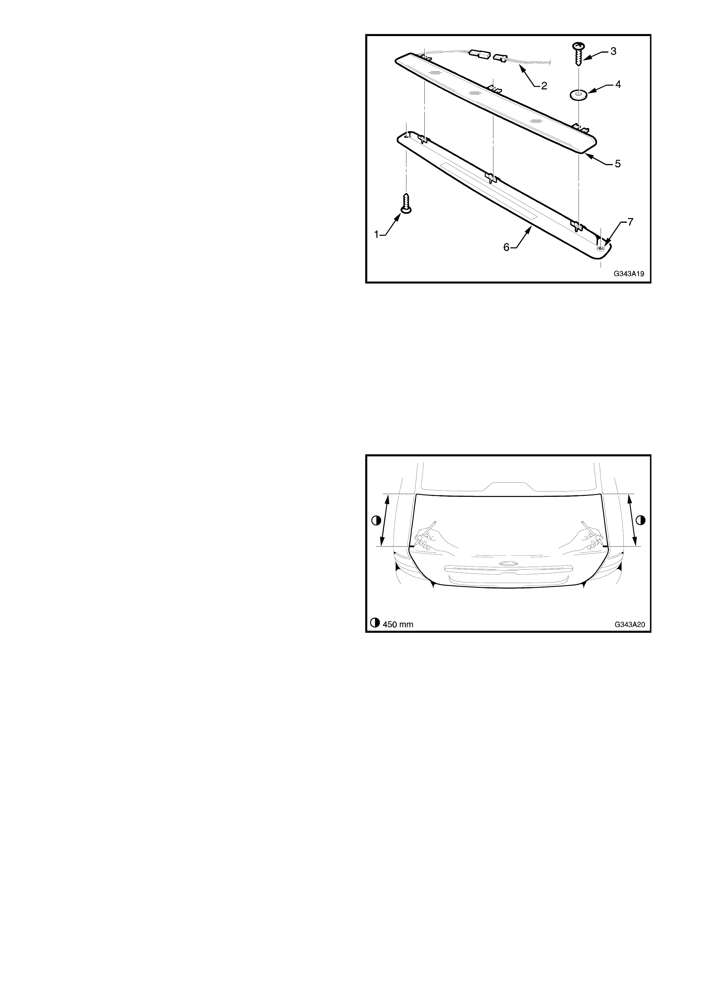
5. If required, remove and disassemble the high
mount stop lam p assembly as shown in Fig 3A-
19.
Remove the screw (1) from each side and
disconnect the wiring connec tor ( 2) . Remove the
screw (3) and washer (4) from three places.
Separate the stop lam p (5) f rom the lower cover
(6).
NOTE: Once removed the high mount stop lamp to
spoiler attaching screws (1) must be discarded and
replaced with new ones.
Figure 3A-19
INSTALL
NOTE 1: Correct installation of the spoiler has the
high mount stop lamp harness routed through the
LH side of the deck lid. Some installations may find
it on the RH side. Regardless, the harness must
route through the conduit on the LH hinge.
NOTE 2: If the deck lid has not been replaced
proceed to Step 10.
1. Mark the deck lid on each side, 450 mm from
the front corner of the deck lid.
2. W ith the aid of an as sistant, place the spoiler on
the deck lid, aligning the rear of the s poiler pos ts
with the marks on the deck lid.
3. Ensure the spoiler is evenly spaced from each
side of the deck lid and mark around the posts.
4. Remove the spoiler
Figure 3A-20
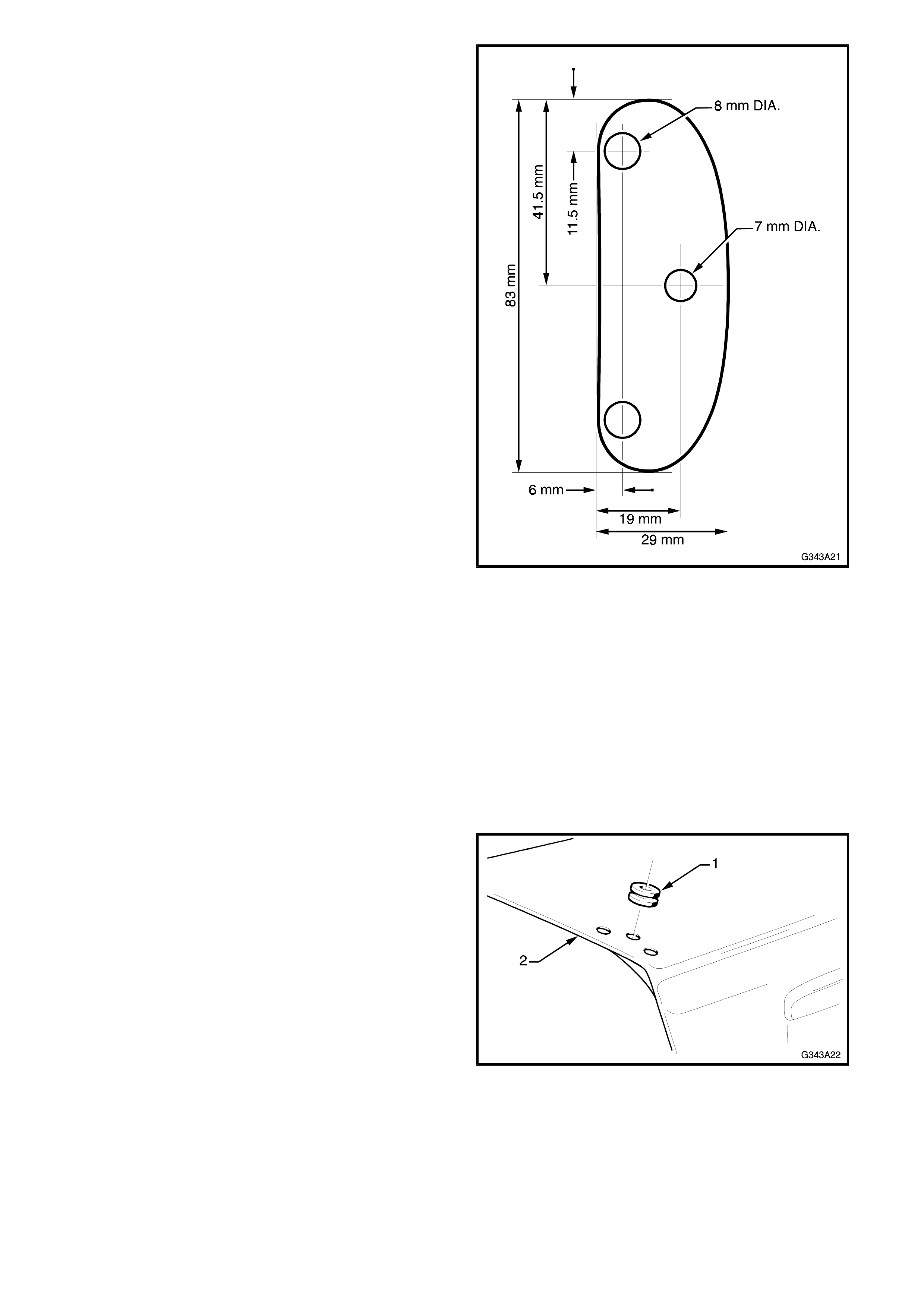
5. Construct a drilling template from light card
using the dimensions shown in Fig. 3A-21.
Figure 3A-21
6. Place the template on the deck lid, aligning it
with the marks.
7. Mark the spoiler mounting holes and on the LH
side only, the high mount stop lamp harness
hole.
8. Initially drill 3 m m holes, f ollowed by 8 mm holes
for the mounting holes and 7 mm for the
harness hole.
IMPORTANT: Drill the high mount stop lamp
harness hole through the outer panel only.
9. Debur the drill holes and apply primer to the
bare metal.
10. Fit the rubber gromm et (1) to the wiring harness
hole in the deck lid (2).
Figure 3A-22
11. Assemble the high mount stop lamp to the
spoiler, ensuring the high mount stop lamp
harness is routed to the LH spoiler post.
NOTE: If a new part is supplied, r emove the s tep (7)
from the screw hole in the high mount stop lamp
lower cover (6) as shown in Fig. 3A-19. This allows
a better fit of the stop lamp in the spoiler cavity.

12. Fix the spoiler post seals to the spoiler posts,
use contact adhesive if required.
13. Fit the spoiler to the deck lid, routing the high
mount stop lamp harness through the grommet
in the deck lid.
14. Install the four Allen head screws and washers
and tighten. Refer Fig 3A-18.
15. Route the high mount stop lamp harness (1)
through the deck lid (2), along the LH hinge
conduit (3) and under the parcel shelf as shown
in Fig. 3A-23.
16. Connect the high mount stop lamp wiring to the
stop lamp wiring connector as shown in Fig. 3A-
17. Check the operation of the high mount stop
lamp.
17. Refit deck lid trim if required.
Figure 3A-23
4.2 HATCH
NOTE: W here a rear spoiler is fitted, the gas struts are
upgraded to compensate f or the extr a weight. This must
be taken into consideration if replacing the struts.
REMOVE
1. Open the tailgate and remove the inner trim.
Refer Group 1 in the JR Series Service Manual
or TIS CD-ROM, Vectra B.
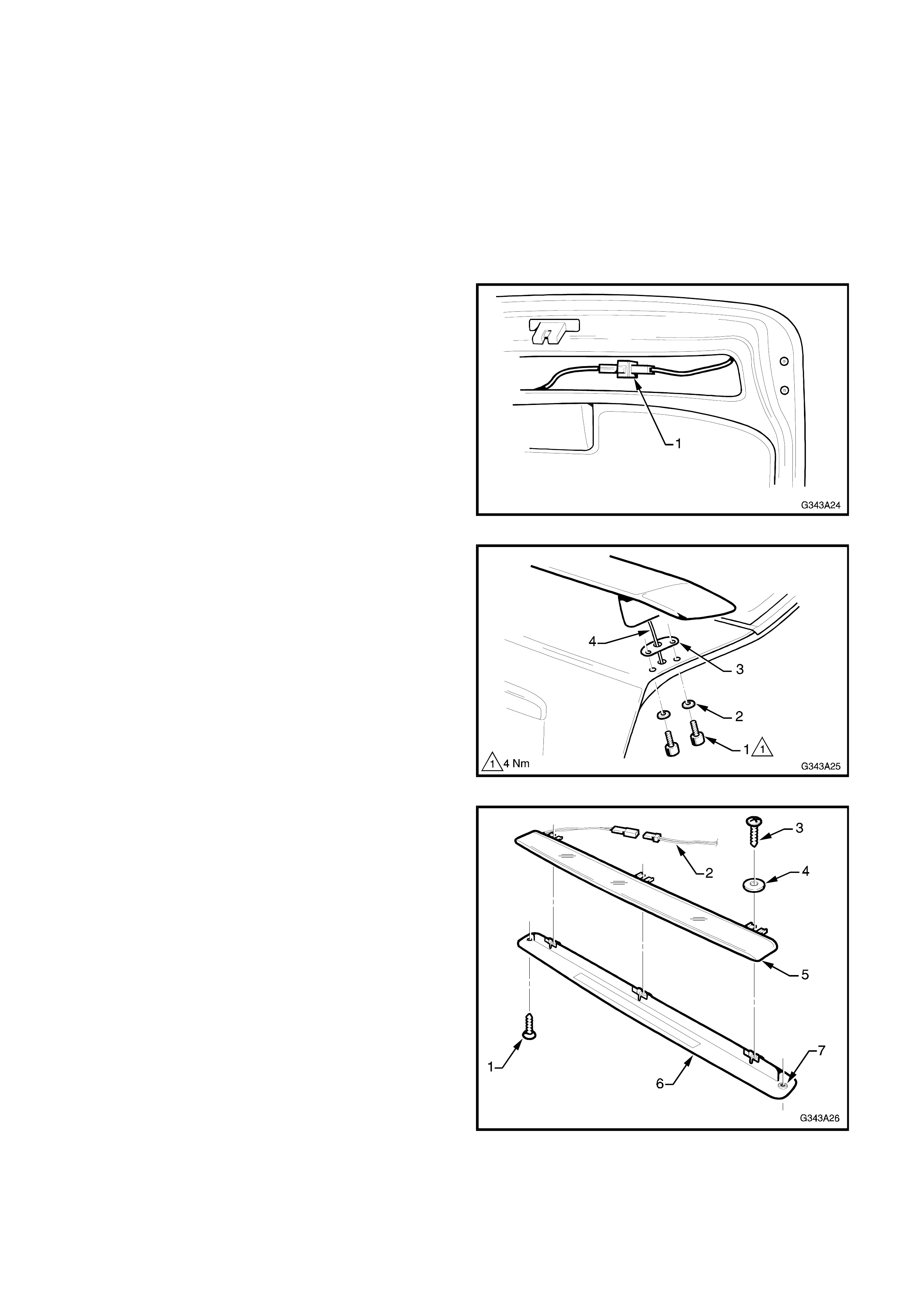
2. Disconnect the high mount stop lamp wiring
connector (1) from within the tailgate cavity.
Figure 3A-24
3. Remove the two screws (1) and washers (2)
attaching the rear spoiler to the tailgate.
Remove the spoiler and seal (3), carefully
pulling the wiring harness (4) through the
grommet hole.
Figure 3A-25
4. If required, remove and disassemble the high
mount stop lam p assembly as shown in Fig 3A-
26.
Remove the screw (1) from each side and
disconnect the wiring connec tor ( 2) . Remove the
screw (3) and washer (4) from three places.
Separate the stop lam p (5) f rom the lower cover
(6).
NOTE: Once removed the high mount stop lamp to
spoiler attaching screws (1) must be discarded and
replaced with new ones.
Figure 3A-26
INSTALL
NOTE: If the tailgate has not been r eplaced pr oc eed
to Step 10.
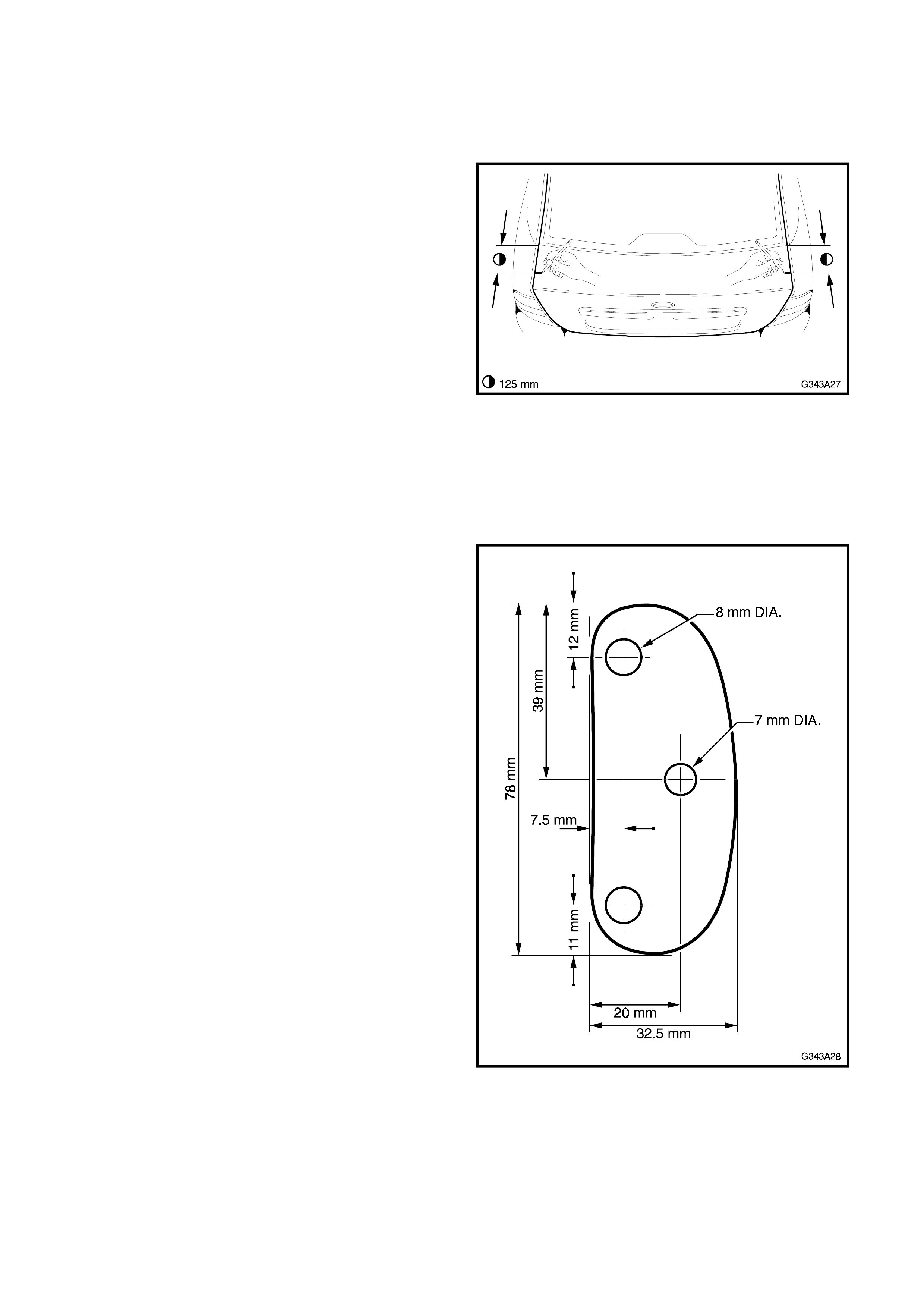
1. Mark the tailgate on each side, 125 mm from the
corner of the rear window moulding.
Figure 3A-27
2. W ith the aid of an as sistant, place the spoiler on
the tailgate, aligning the front of the spoiler posts
with the marks on the deck lid.
3. Ensure the spoiler is evenly spaced from each
side of the tailgate and mark around the posts.
4. Remove the spoiler
5. Construct a drilling template from light card
using the dimensions shown in Fig. 3A-28.
Figure 3A-28
6. Place the template on the tailgate, aligning it
with the marks.
NOTE: Ensure the correct side of the template is
used.
7. Mark the spoiler mounting holes and on one
side only, the high mount stop lamp harness
hole.
8. Initially drill 3 m m holes, f ollowed by 8 mm holes
for the mounting holes and 7 mm for the
harness hole.
IMPORTANT: Drill the high mount stop lamp
harness hole through the outer panel only.
9. Debur the drill holes and apply primer to the
bare metal.
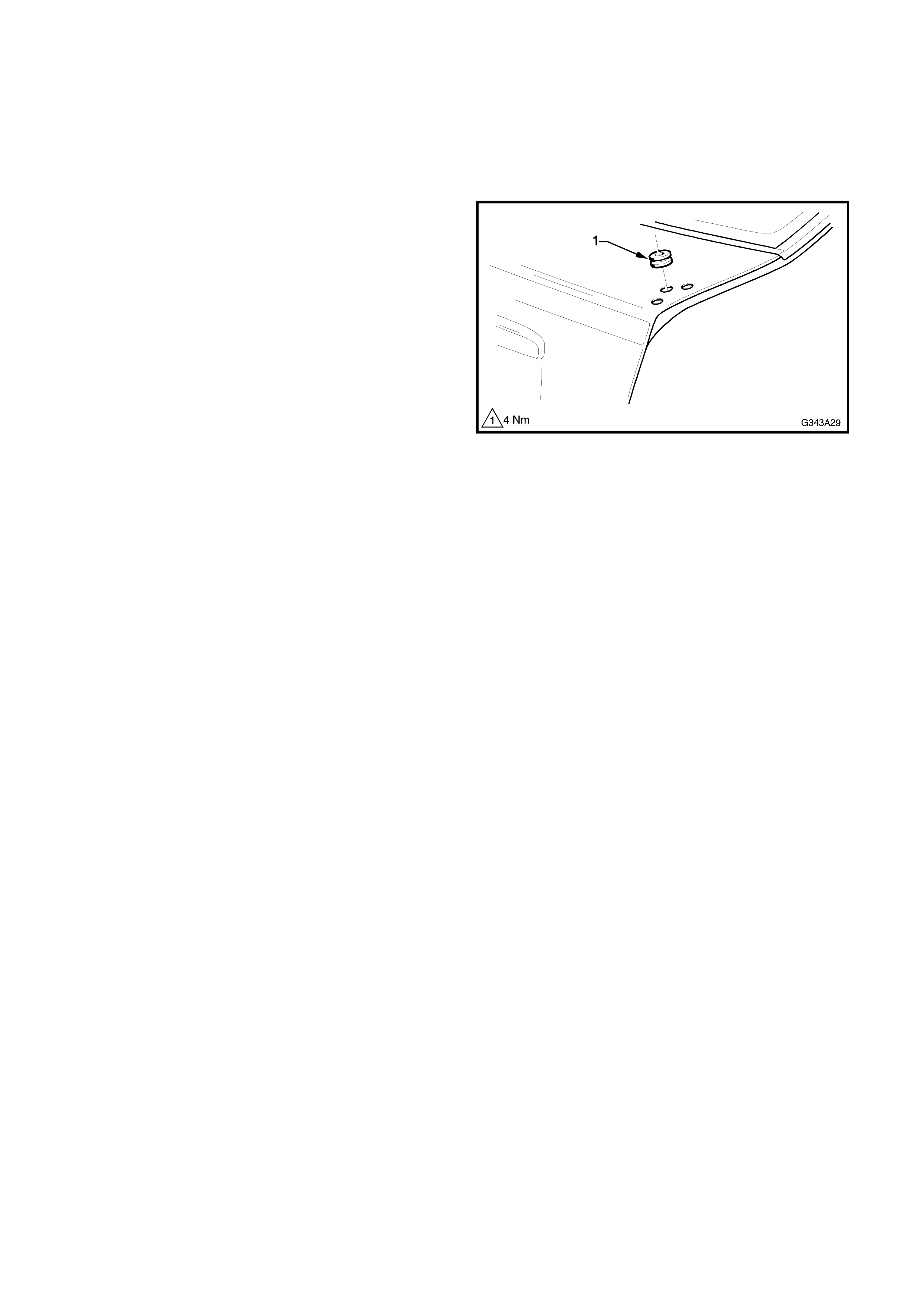
10. Fit the rubber gromm et (1) to the wiring harness
hole.
Figure 3A-29
11. Assemble the high mount stop lamp to the
spoiler.
NOTE: If a new part is supplied, r emove the s tep (7)
from the screw hole in the high mount stop lamp
lower cover (6) as shown in Fig. 3A-26. This allows
a neater fit of the stop lamp in the spoiler cavity
12. Fix the spoiler post seals to the spoiler posts,
use contact adhesive if required.
13. Fit the spoiler to the tailgate, routing the high
mount stop lamp harness through the grommet
in the tailgate.
14. Install the four Allen head screws and washers
and tighten. Refer Fig 3A-25.
15. Connect the high mount stop lamp connector
within the tailgate cavity as shown in Fig 3A-24.
16. Close the tailgate and check the oper ation of the
high mount stop lamp.
17. Refit tailgate trim.
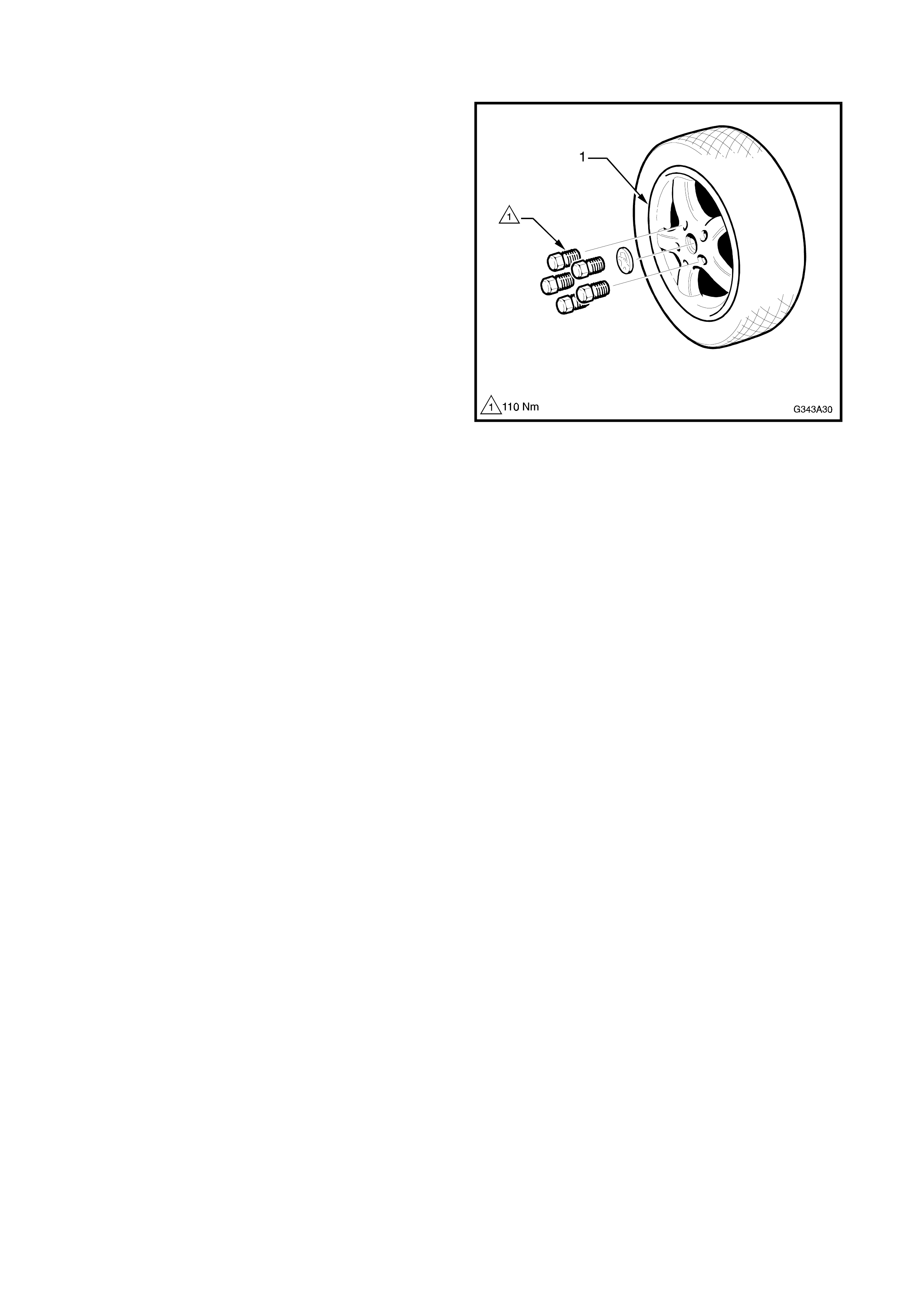
5. ALLOY WHEELS
A unique 15” x 6” 5 spoke alloy wheel is available
for the Holden By Design Vectr a Vehicles, as either
part of the id package or individually. The existing
tyres are r etained as is the standar d steel rim spare
wheel.
This Section of the Holden By Design Service
Information Supplement illustrates the wheel type
only. For the inf orm ation requir ed to servic e wheels,
refer to Group E, in Volume 2 of the JR Series
Service Manual or TIS CD-ROM, Vectra B.
Figure 3A-30
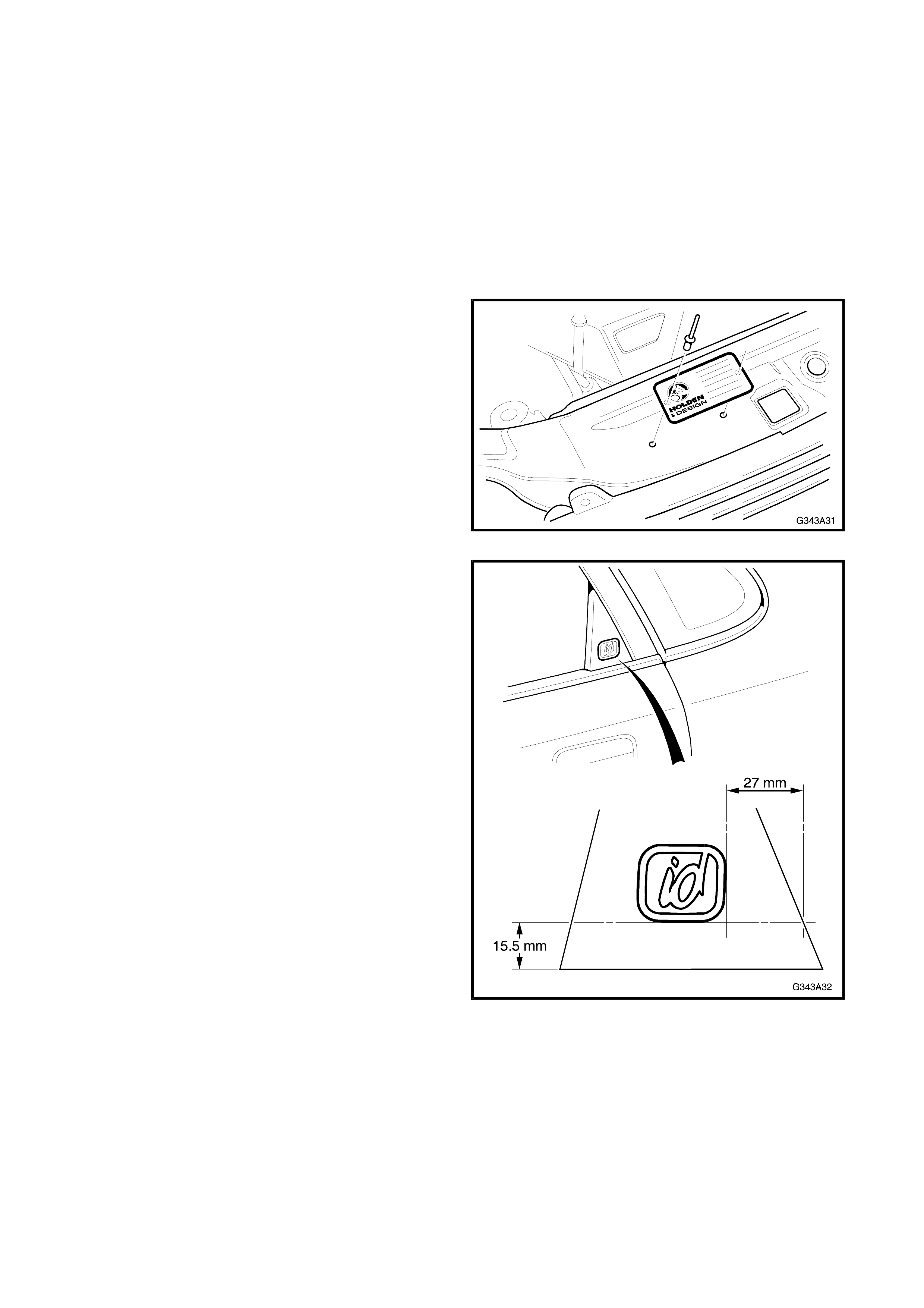
6. IDENTI FICATION & BADGING
W her e a full Holden By Design id kit has been ins talled,
a HBD identification plate is installed onto the radiator
support panel with pop-rivets.
Holden By Design id emblems are affixed onto each
rear door window filler plate with double sided adhesive
tape.
NOTE: The HBD identification plate replaces the air-
conditioning label, which is relocated to the lower, left
side of the bonnet frame.
Figure 3A-31 shows the location of the HBD
identification plate. The existing holes in the radiator
support panel are used.
Figure 3A-31
Figure 3A-32 shows the location of the id emblem and
the positioning measurements on the rear door
window filler plate.
Figure 3A-32