
SECTION 4A & 4B - VT SERIES BODY KITS
& ALLOY WHEELS
CAUTION:
This vehicle will be equipped with a Supplemental Restraint System (SRS). A SRS will consist of
either seat belt pre-tensioners and a driver’s air bag, seat belt pre-tensioners and a driver’s and
front passenger’s air bags or seat belt pre-tensioners, driver’s and front passenger’s air bags
and left and right hand side air bags. Depending upon the system fitted, refer to SAFETY
PRECAUTIONS, Section 12M Supplemental Restraint System in the VT Series I Service
Information, before performing any service operation on or around any SRS components, the
steering mechanism or wiring. Failure to follow the SAFETY PRECAUTIONS could result in SRS
deployment, resulting in possible personal injury or unnecessary SRS system repairs.
CAUTION:
This v ehicle may be equipped w ith LPG ( Liquefied Pet roleum Gas). In the interests o f safety, t he
LPG fuel system should be isolated by turning 'OFF' the manual service valve and then draining
the LPG service lines, before any service work is carried out on the vehicle. Refer to the LPG
leaflet included with the Owner's Handbook for details or in the VT Series I Service Information
for more specific servicing information.
1. GENERAL INFORMATION
This Section of the Holden By Design Service Inform ation Supplem ent describes the rem oval and installation of
the aerodynamic id body styling kit components and alloy wheels available for VT Series Vehicles.
The id body styling kit consists of a front spoiler, unique side skirts for sedan and wagon variants, unique rear
bumper extensions for sedan and wagon variants and a rear deck lid spoiler or extension for sedan variants.
Three unique deck lid spoilers / are available:
• a low profile deck lid ‘lip’ extension,
• a stylised ‘Manta’ deck lid spoiler incorporating a high mount stop lamp, and
• the deck lid spoiler as used with S-Pack series vehicles, which also incorporates a high mount stop lamp.
W hen a complete kit is fitted, a Holden By Design identification plate and id badging are included as part of the
package.
NOTE: Vehicles can be supplied with only one or several of the com ponents. In this case no Holden By Design
badging is included.
Alloy wheels can be included as part of the id kit or optioned separately. Three styles are available for the VT
series, each a unique style and size.
Figure 4A-1 illustrates the VT id body kit major components and alloy wheels.
For information not contained in this Section, refer to Section 1, BODY of the VT Series I Service Information.
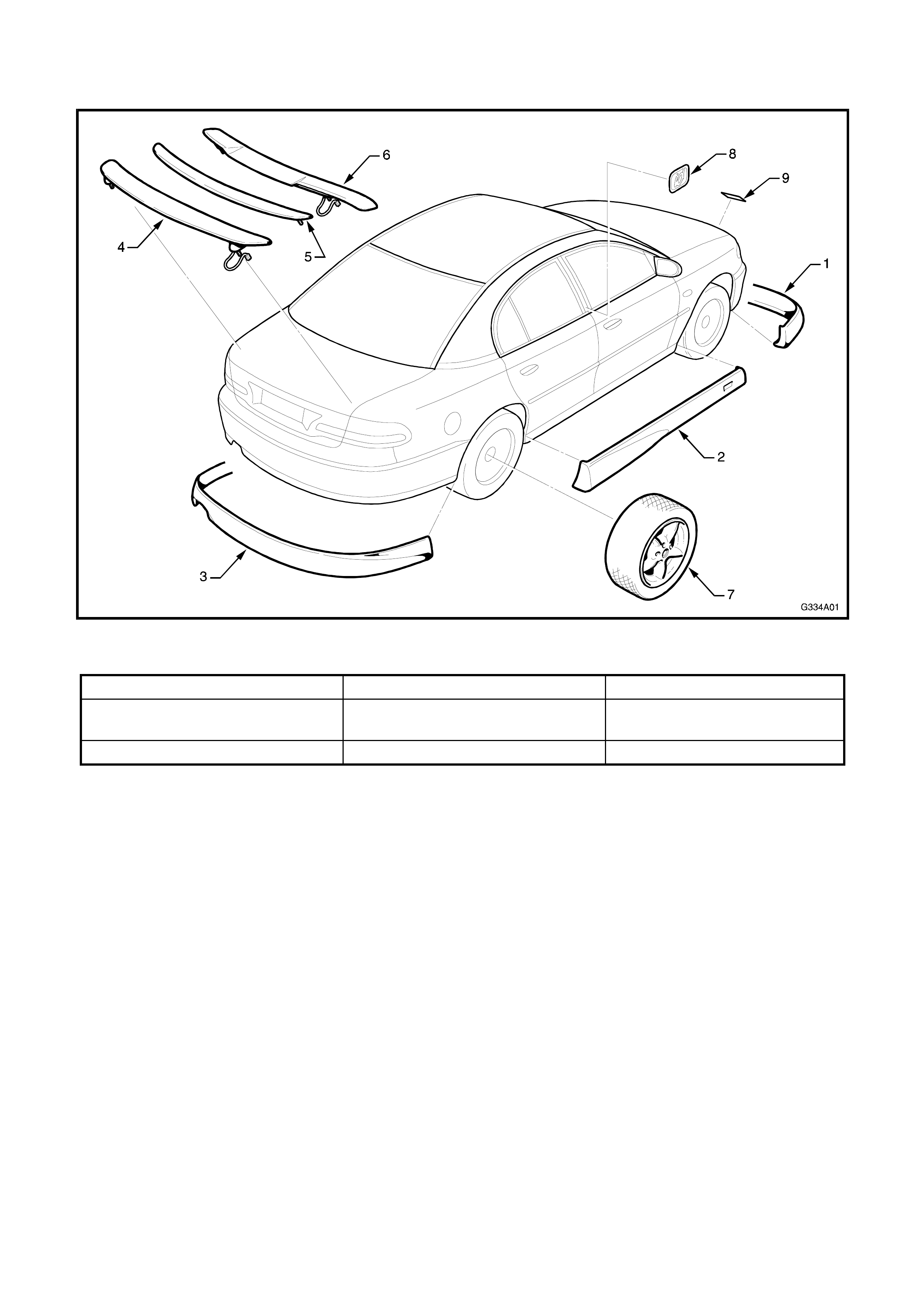
1.1 MAJOR COMPONENTS
Figure 4A-1
1. Front spoiler 4. S-Pack type rear spoiler 7. Alloy wheel
2. Side skirt 5. Low profile deck lid
extension 8. id badge
3. Rear bumper extension 6. Manta type rear spoiler 9. Holden By Design plate
2. FRONT SPOILER
The front spoiler is attached to the bumper facia with screws. No adhesive is used.
NOTE 1: The front bumper facia must be removed prior to the bumper extension. This is required to allow
access to the attaching screws. Refer to Section 1D, BUM PER BARS of the VT Series I Ser vice Infor m ation for
this procedure.
NOTE 2: The front bumper extension is painted in the vehicle’s body colour. The painting procedures are
relatively straight forward, providing the c orrec t steps are f ollowed. Refer to Section 1D, BUM PER BARS of the
VT Series I Service Information for further information.
REMOVE
1. Place the bum per f acia ass em bly upside down on
a clean, soft surface.
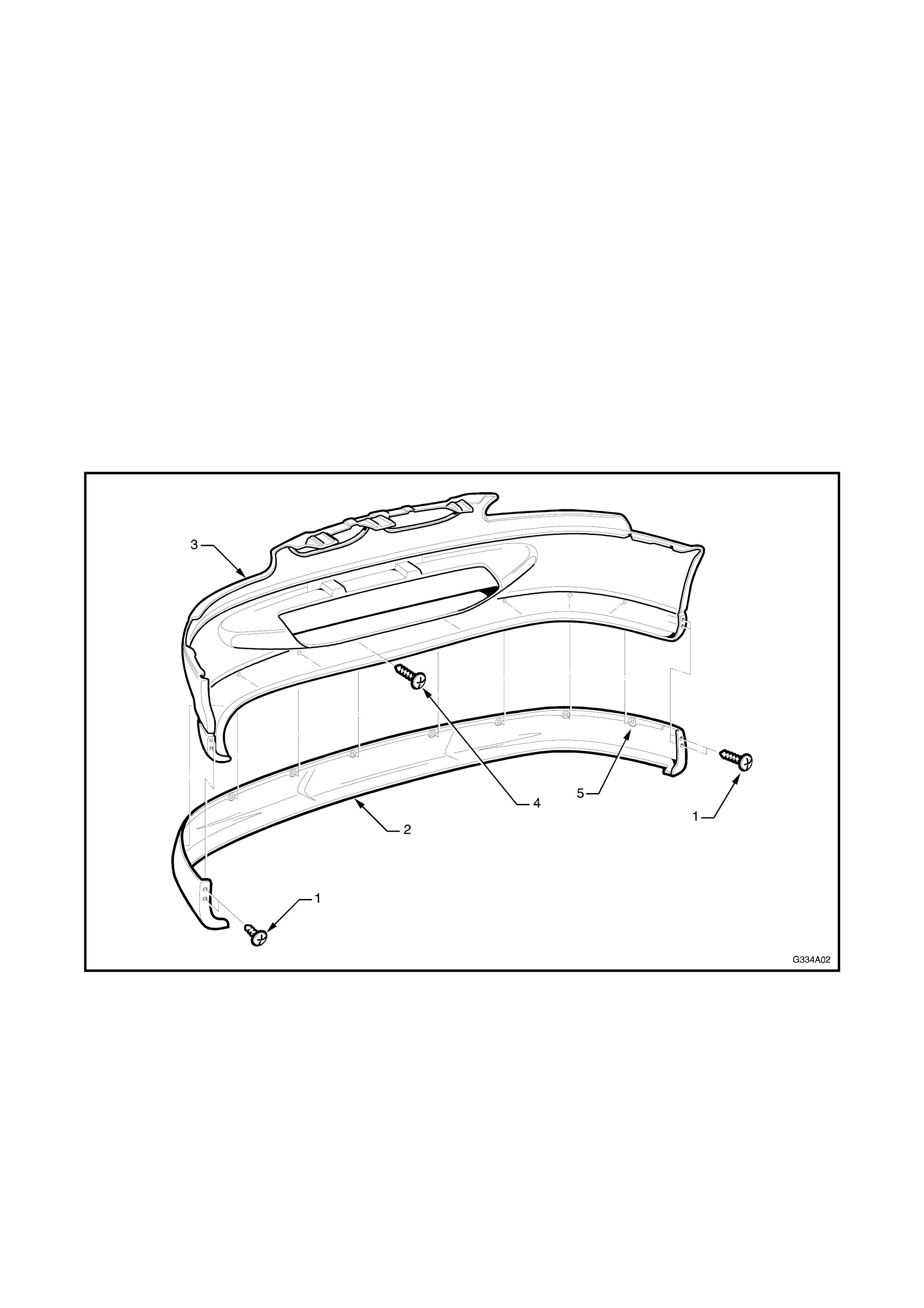
2. Remove the two screws (1) securing each end of
the front spoiler (2) to the front bumper facia (3).
Refer Fig. 4A-2.
3. Remove the eight sc r ews (4) from the r ear s ide of
the bumper facia.
4. Remove the spoiler.
Figure 4A-2
INSTALL
NOTE: If the bumper facia has not been replaced,
proceed to Step 7.
1. Either,
A - Place a dob of thick paint or lik e on the c entre
of each s crew hole area (5) and with the aid of an
assistant carefully fit the spoiler in position,
transferring the paint onto the bumper facia, or
B - Construct a drilling template f rom light card to the
dimensions shown in Fig. 4A-3.
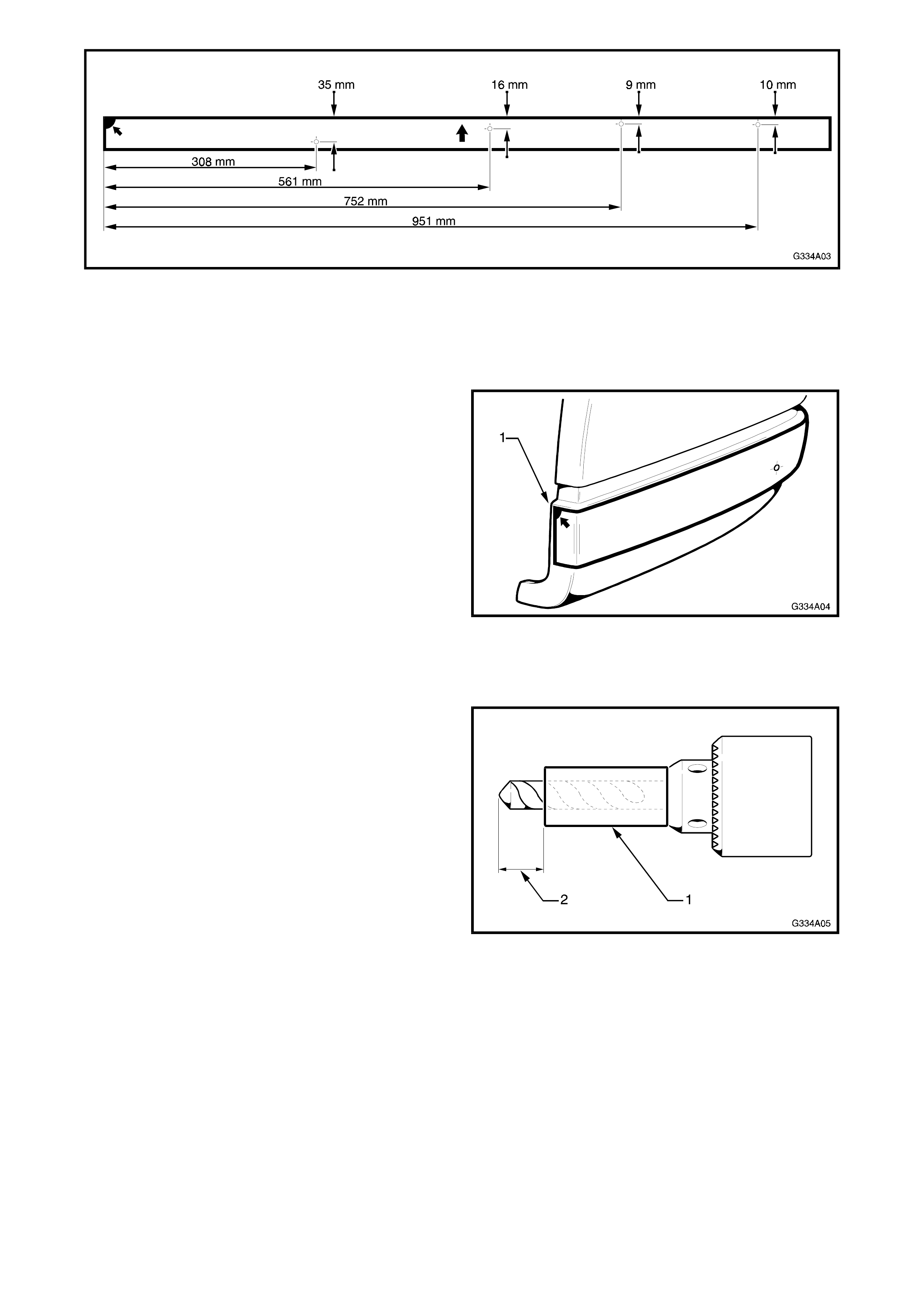
Figure 4A-3
2. If the paint marks were placed on the facia,
compare the centre of the remaining paint on the
spoiler with the corresponding mark on the facia.
Determine the centre point and mark the facia
accordingly.
3. If the template was constructed, starting at the
RH inner corner of the bumper facia wheel arch
opening, place the template on the bumper facia.
Align the top edge of the template with the lower
edge of the ridge in the f acia as shown (1) in Fig.
4A-4.
4. Mark the bumper facia with the four screw holes
for the RH side.
5. Turn the template over, align it as previously
mentioned and mark the four holes for the LH
side.
Figure 4A-4
6. Drill the screw holes using a 3 mm drill bit.
7. With the aid of an assistant, place the bumper
extension in its correct position.
8. From the rear side of the bumper facia, drill
through the eight screw holes into the bumper
extension with a 3 m m drill bit to a depth of 7 mm.
Begin in the middle and progressively work to
each end.
NOTE: A snug fitting piece of tube (1) fitted over the
drill bit can be used as a spacer to restrict drill tip
depth (2).
Figure 4A-5
8. Install the eight screws.
9. Drill two 3 mm screw holes at each end of the
bumper extension through the bumper facia.
10. Install the screws.
11. Refit bumper assembly
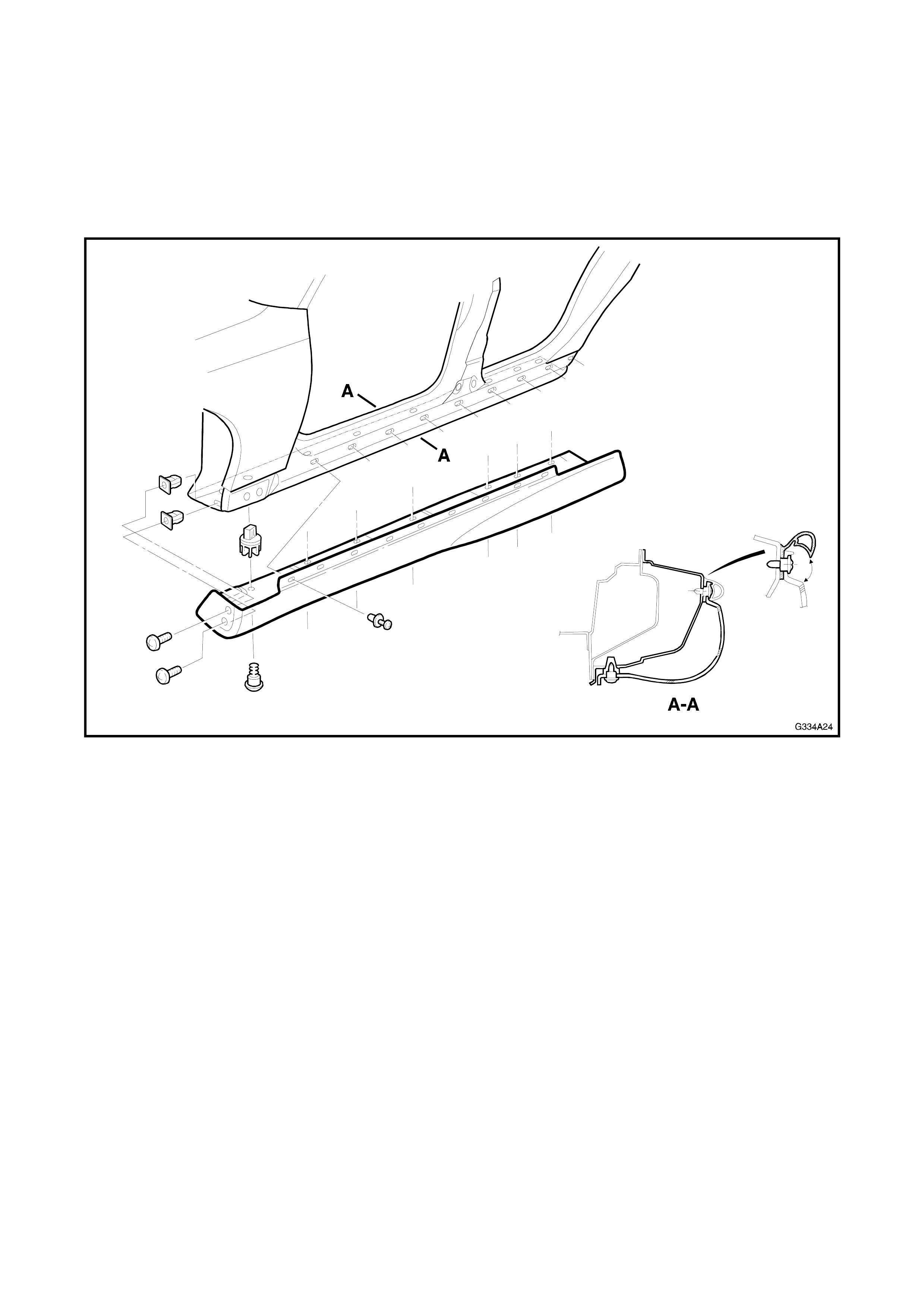
3. SIDE SKIRTS
The Holden By Design side skirt assemblies replace the existing rocker panel skirts. The procedures for their
removal is the same as the standard skirt. Refer to Section 1A9, EXTERIOR ORNAMENTATION of the VT
Series I Service Information for this procedure.
NOTE: The side skirts are painted in the vehicle’s body colour. The painting procedures are relatively straight
forward providing the correct steps are followed. Refer to Section 1D, BUMPER BARS of the VT Series I
Service Information for further information.
Figure 4A-6
4. REAR BUMPER EXTENSION
The rear bumper extension is attached to the rear bumper facia with screws. No adhesive is used. While the
rear bum per ex tensions dif fer for Sedan and Wagon variants, the service pr ocedures for both are the s am e with
the exception of the drilling templates and the number of screws required.
NOTE 1: The rear bumper facia must be removed prior to the bumper extension. This is required to allow
access to the attaching screws. Refer to Section 1D, BUM PER BARS of the VT Series I Ser vice Infor m ation for
this procedure.
NOTE 2: The rear bumper extensions are painted in the vehicle’s body colour. The painting procedures are
relatively straight forward providing the c orrect steps are followed. Refer to Section 1D, BUM PER BARS of the
VT Series I Service Information for further information.
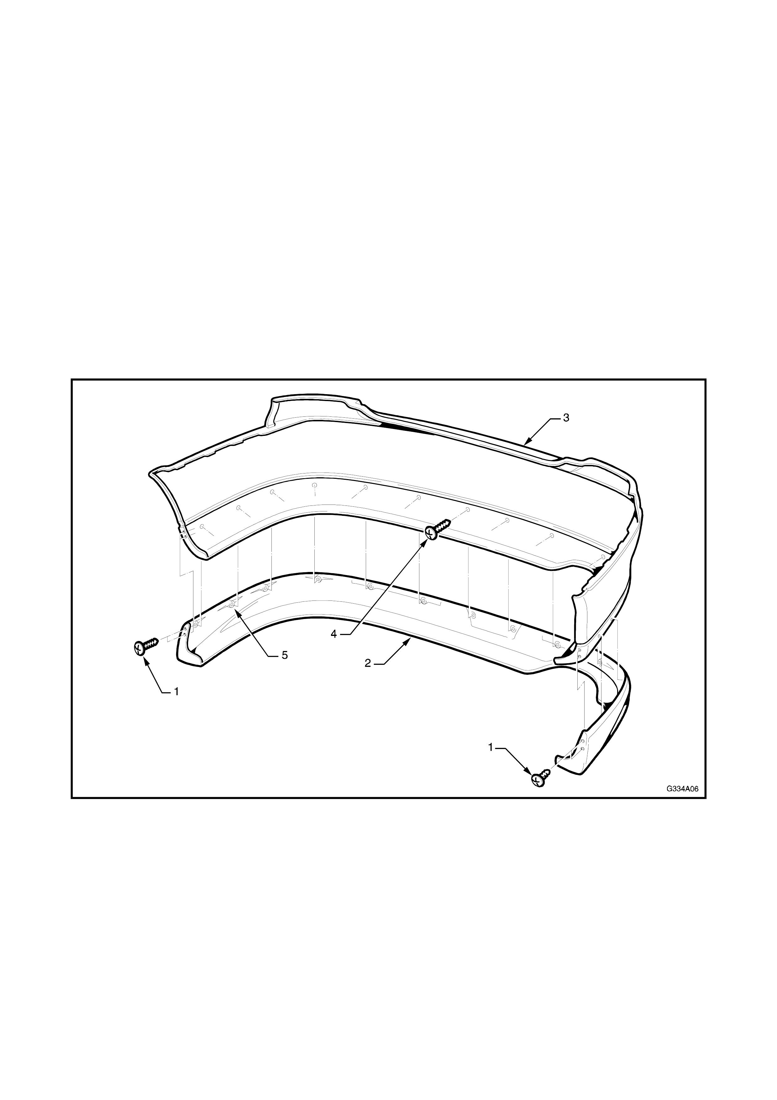
REMOVE
1. Remove the two screws (1) securing each end of
the rear bum per extension (2) to the rear bumper
facia (3). Refer Fig. 4A-7.
2. Remove the screws (4) from inside the bumper
facia. Twelve screws for sedan, ten screws for
wagon.
3. Remove the bumper extension.
Figure 4A-7
INSTALL
NOTE: If the bumper facia has not been replaced,
proceed to Step 6.
1. Either,
A - Place a dob of thick paint or lik e on the c entre
of each s crew hole area (5) and with the aid of an
assistant carefully fit the extension in position,
transferring the paint onto the bumper facia, or
B - Construct a drilling template f rom light card to the
dimensions shown A, sedan or B, wagon in Fig.
4A-8.
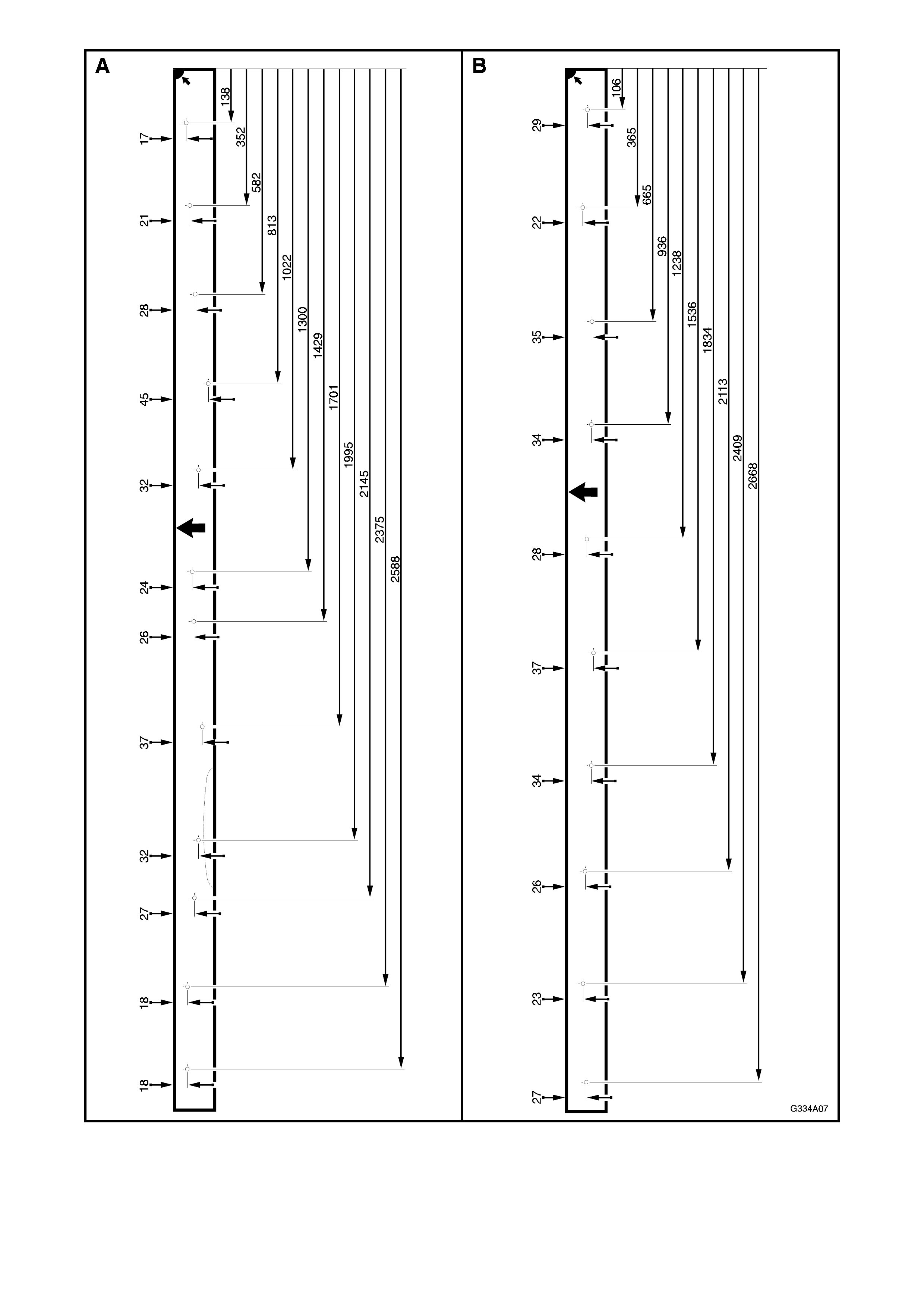
Figure 4A-8
2. If the paint marks were placed on the facia,
compare the centre of the remaining paint on the
extension with the corresponding mark on the
facia. Determine the centre point and mark the
facia accordingly.
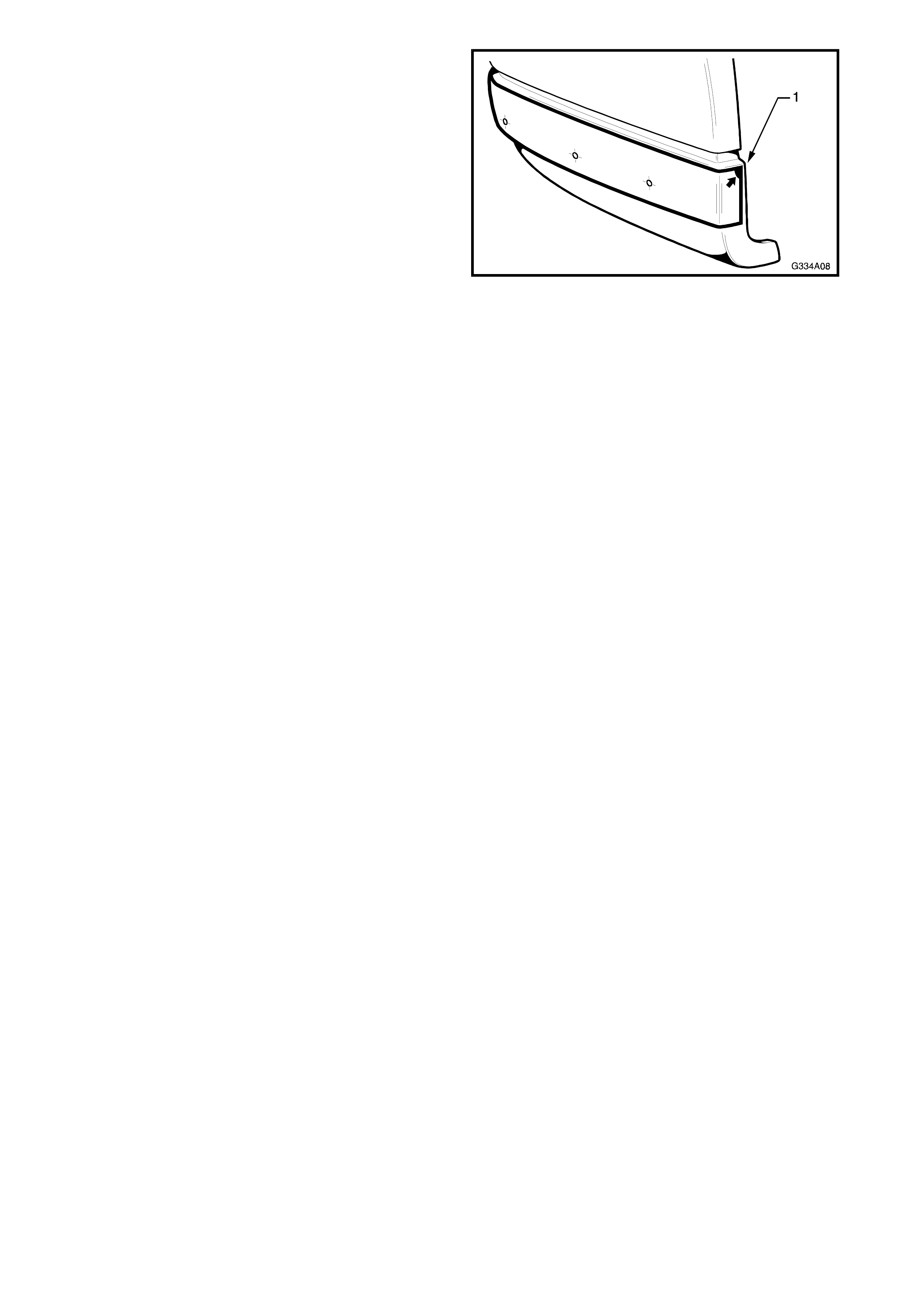
3. If the template was constructed, starting at the
RH inner corner of the bumper facia wheel arch
opening, place the template on the bumper facia.
Align the top edge of the template with the lower
edge of the ridge in the f acia as shown (1) in Fig.
4A-9.
4. Mark the bumper facia with the twelve screw
holes for sedan or ten screw holes for wagon.
Figure 4A-9
5. Drill the screw holes as marked with a 3 mm drill
bit.
6. With the aid of an assistant, place the bumper
extension in its correct position.
7. From the rear side of the bumper facia, drill
through the screw holes into the bumper
extension with a 3 mm drill bit to a depth of 7 mm.
NOTE: A snug fitting piece of tube fitted over the drill
bit can be used as a spacer to restrict drill tip depth.
Refer Fig. 4A-5.
8. Install the screws.
9. Drill the two 3 mm s crew holes at eac h end of the
bumper extension through the bumper facia.
10. Install the screws.
11. Refit bumper assembly.
5. DECK LID EXTENSIONS / SPOILERS
Three Holden By Design rear deck lid extensions / spoilers are available. Each is attached to the deck lid with
screws and / or nuts, no adhesive is used.
Closed cell foam tape is placed around the circumference of the Low Profile extension and Manta spoiler to
provide a water and dust proof seal between the spoiler and deck lid surface.
Differences between the spoilers necessitate a unique procedure for each type.
NOTE: The spoilers are painted in the vehicle’s body colour. The painting procedures are relatively straight
forward providing the correct steps are followed. Refer to Section 1D, BUMPER BARS of the VT Series I
Service Information for further information.
5.1 LOW PROFILE DECK LID EXTENSION
REMOVE
1. Open the deck lid and remove the deck lid inner
trim, if fitted. Ref er to Section 1, BODY of the VT
Series I Service Information.
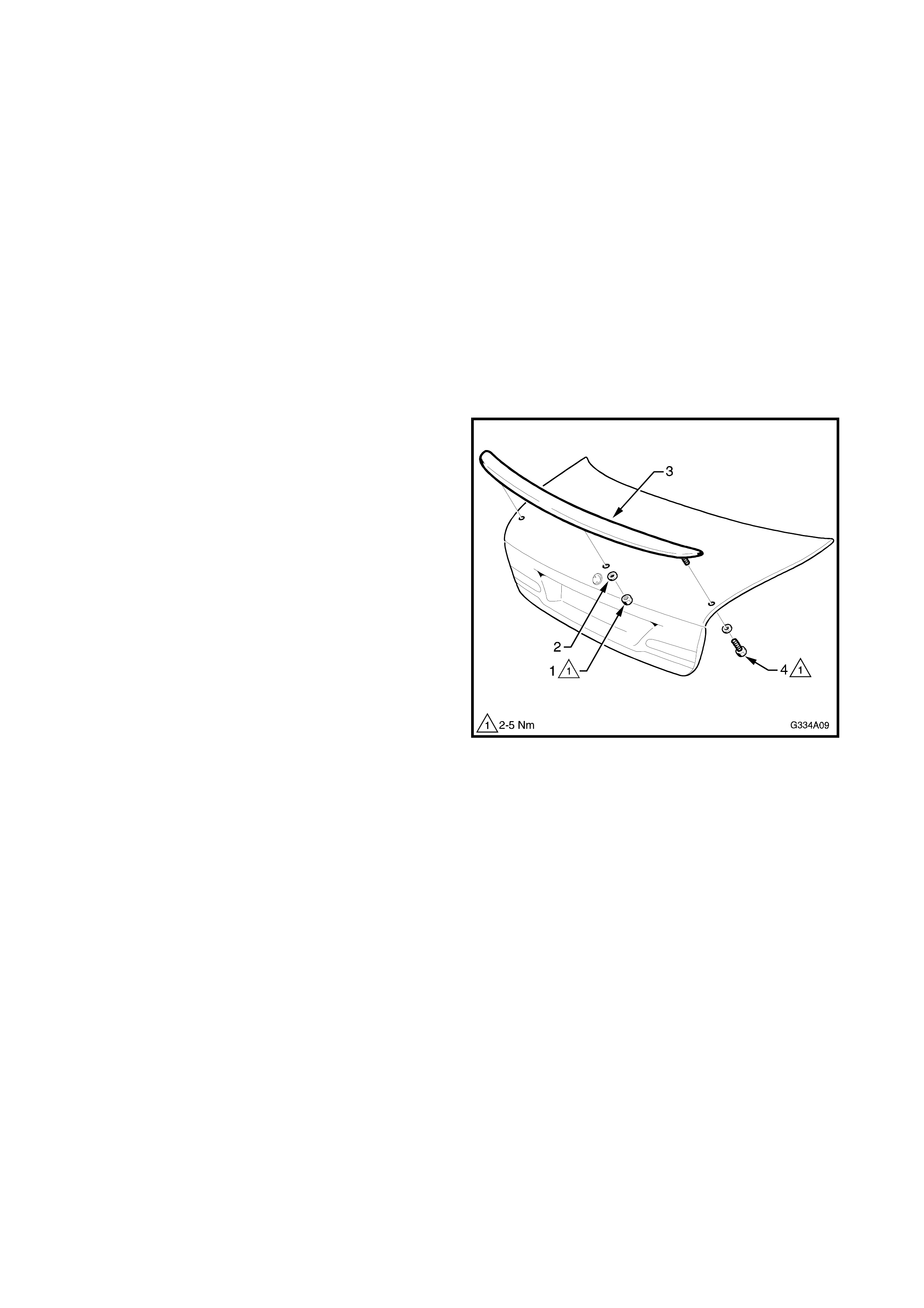
2. From the underside of the deck lid, remove the
nut (1) and washer (2) attaching the centr e of the
deck lid extension (3) to the deck lid.
3. Remove the screw (4) and washer attaching each
end of the extension to the deck lid.
4. Remove the extension.
Figure 4A-10
INSTALL
NOTE: If the deck lid has not been replaced, proceed
to Step 8.
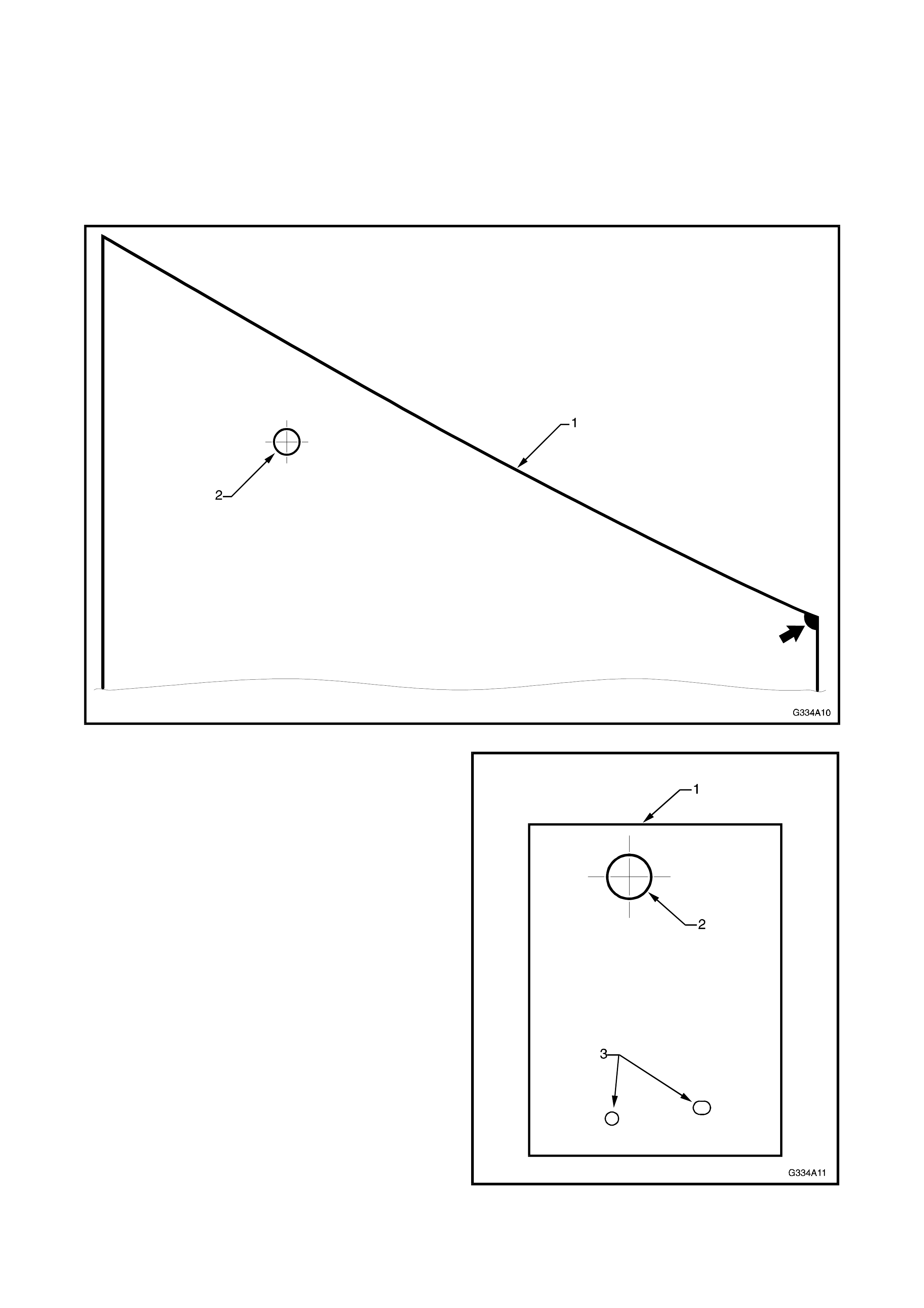
1. C onstruct a drilling tem plate (1) f rom light car d by
photocopying or tracing, for the outer mount hole
(2) as shown in Fig. 4A-11.
Figure 4A-11
2. Construct a drilling template (1) from light card, by
photocopying or tracing, for the c entre mount hole
(2). Mark the positions for the emblem stud holes
(3) as shown in Fig. 4A-12.
Figure 4A-12
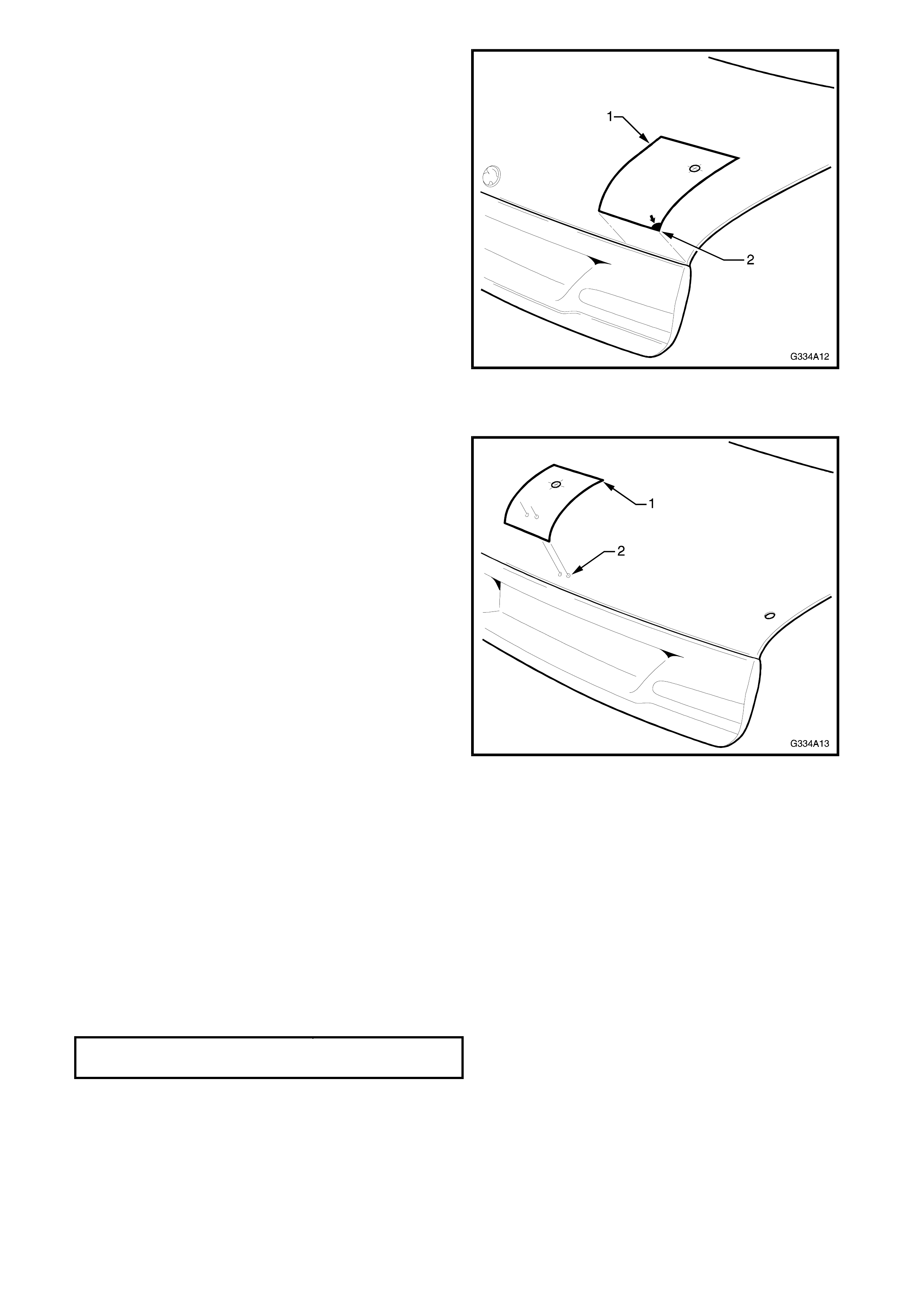
3. Place the outer tem plate (1) on the RH side of the
deck lid. The arrow (2) aligns with the corner of
the deck lid as shown. Mark the mounting hole.
Figure 4A-13
4. Turn the template over and place it on the LH
side of the deck lid. Mark the mounting hole.
5. Place the centre template (1) on the deck lid,
aligning the deck lid emblem holes (2). Mark the
mounting hole.
Figure 4A-14
6. Carefully drill the mount holes. Initially drill 3 mm
holes, followed by 10 mm holes.
7. Debur the drill holes and apply primer to the bare
metal.
8. Apply closed cell foam tape or sealing com pound
as originally used to the underside of the spoiler,
around the mounting surface circumference. This
acts as a gasket, sealing out dirt and moisture.
9. Fit the spoiler to the deck lid.
10. Fit the screw, nuts and washers to the studs and
hand tighten.
11. Chec k alignm ent of spoiler on dec k lid and tighten
the screw and nuts to the specified torque.
DECKLI D E XTENSION MOUNTI NG
SCREW AND NUTS 2-5 Nm
12. Refit deck lid inner trim, if removed.
5.2 S-PACK SPOILER
REMOVE
1. Open the deck lid and remove the deck lid inner
trim, if fitted. Ref er to Section 1, BODY of the VT
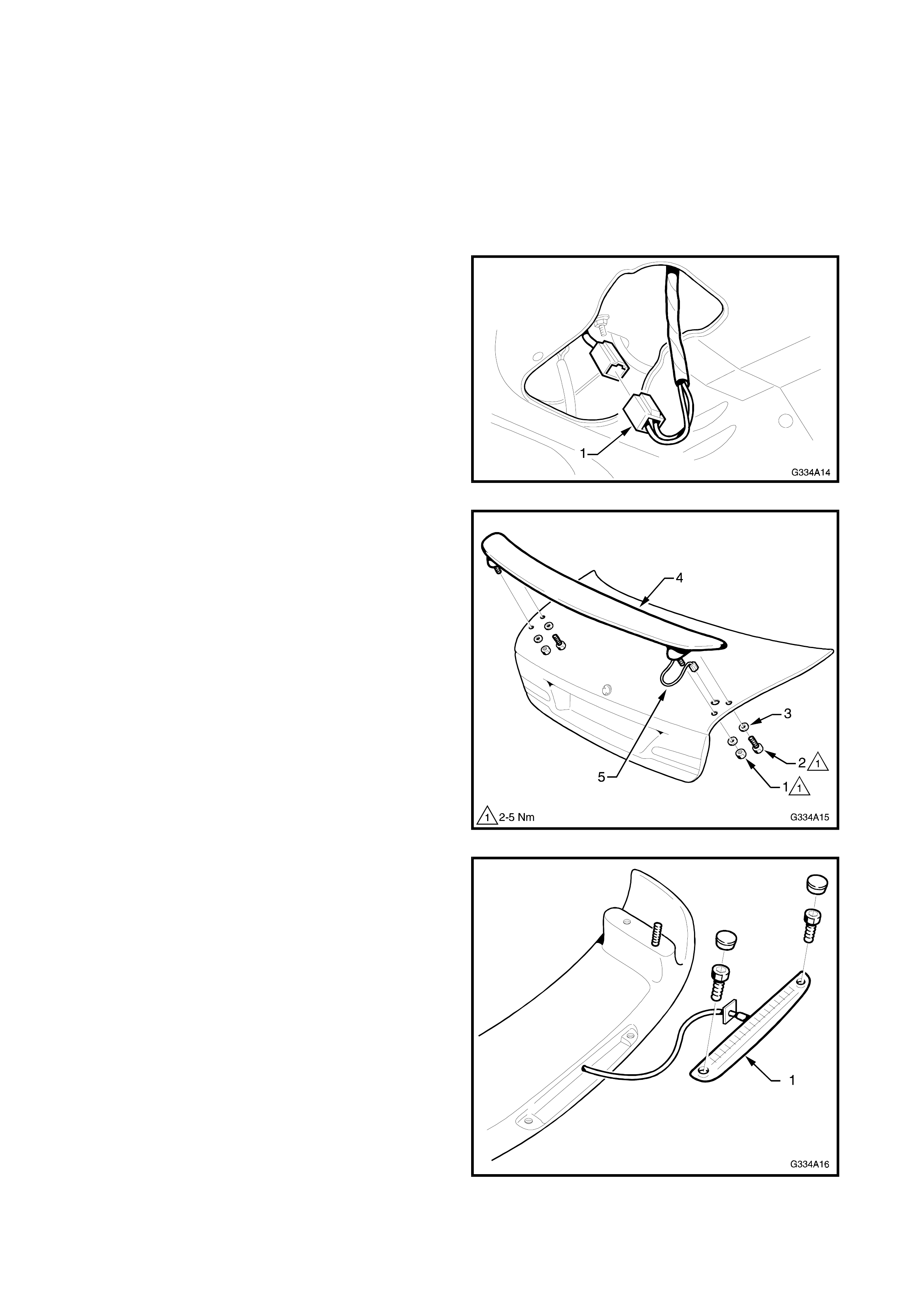
Series I Service Information. Disconnect the high
mount stop lamp connector (1) from within the
deck lid cavity.
2. Remove each wiring terminal from the spoiler
harness c onnector body. Inserting a scribe or like
into the front s ide of the connec tor cavity, depress
the tab to release the term inal from the connector
body.
F
Figure 4A-15
3. Remove the nut (1), screw (2) and washers (3)
securing each side of the spoiler (4) to the deck
lid.
4. While feeding the high mount stop lamp wiring
harness (5) through the access hole in the deck
lid, remove the spoiler.
Figure 4A-16
5. If required, remove the high mount stop lamp
assembly (1).
Figure 4A-17
INSTALL
NOTE: If the deck lid has been not been replaced
proceed to Step 7.
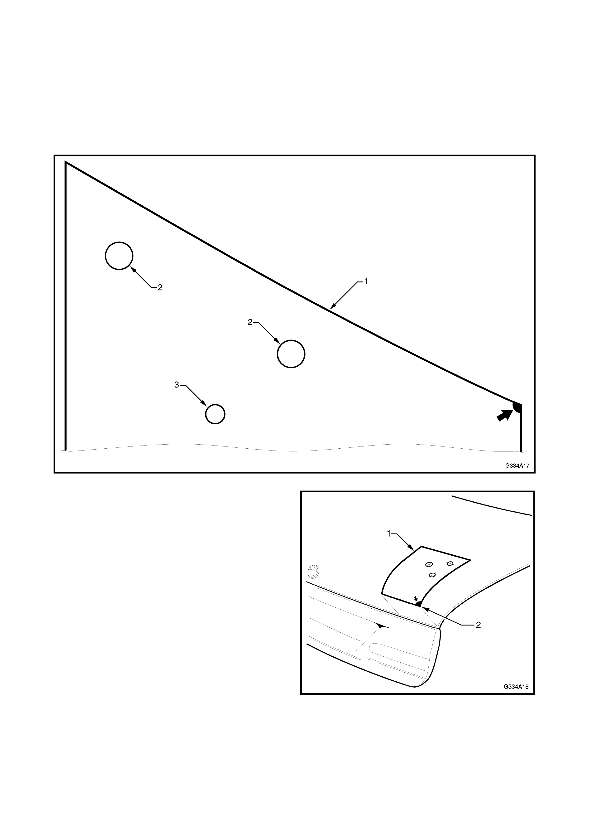
1. C onstruct a drilling tem plate (1) f rom light car d by
photocopying or tracing. Mar k the m ounting holes
(2) and the wiring harness hole (3) for the RH
side only, as shown in Fig. 4A-18.
Figure 4A-18
2. Place the template (1) on the RH side of the deck
lid ensuring the arrow aligns to the corner of the
deck lid as shown.
Figure 4A-19
3. Mark the spoiler mounting holes and the high
mount stop lamp harness hole.
4. Turn the template over and place it on the LH
side.
NOTE: Mark the spoiler mounting holes ONLY.

5. Drill the mounting holes. Initially drill 3 mm,
followed by 10 mm holes for the mountings and 9
mm for the wiring harness.
NOTE: Drill the high mount stop lamp harness hole
through the outer panel only.
6. Debur the drill holes and apply primer to the bare
metal.
7. Assemble the high mount stop lamp to the
spoiler, if previously removed. Refer Fig. 4A-17.
8. Fit the spoiler to the deck lid while feeding the
high mount stop lamp wiring harness through its
hole in the deck lid. Refer Fig. 4A-16.
NOTE: Early spoilers were fitted with an O-ring to the
underside of the s poiler pos ts. This was r eplaced by a
gasket which is bonded to the posts on later spoilers.
Ensure the O-rings or gaskets are in place before
fitting the spoiler.
8. From the underside of the deck lid, install the
washers and the nuts to the protruding studs as
shown in Fig. 4A-16.
9. Temporarily fix the spoiler into position and hand
tightening the nuts.
10. Ensure the spoiler is in the correct position.
11. Install the washers and screws as shown in Fig.
4A-16. Tighten all fasteners to the specified
torque.
S-PACK SPOI LE R MOUNT I NG
SCREW AND NUTS 2-5 Nm
12. Fit the high mount stop lamp connector pins into
the connector body and join the wiring connector
within the deck lid cavity as shown in Fig. 4A-15.
13. Check high mount stop lamp operation.
14. Refit deck lid inner trim, if removed.
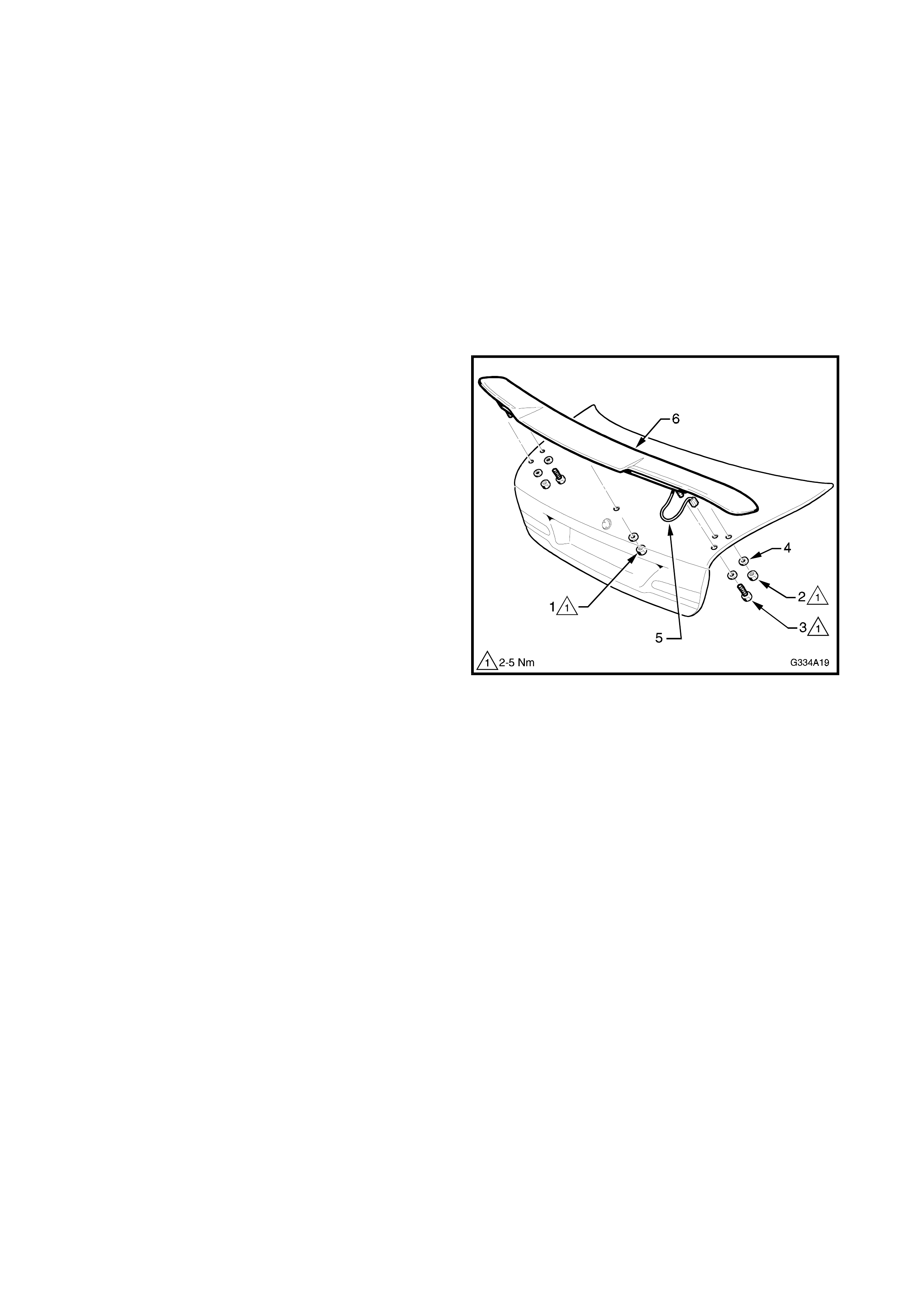
5.3 MANTA DECK LID SPOILER
REMOVE
1. Open the deck lid and remove the deck lid inner
trim, if fitted. Ref er to Section 1, BODY of the VT
Series I Service Information.
2. Disconnect the high mount stop lamp connector
from within the deck lid cavity. Refer to Fig. 4A-
15.
3. Remove each wiring terminal from the spoiler
harness c onnector body. Inserting a scribe or like
into the front s ide of the connec tor cavity, depress
the tab to release the term inal from the connector
body.
4. Remove the centre nut (1) and washer from the
underside of the deck lid.
5. Remove the nut (2), screw (3) and washers (4)
securing each side of the spoiler to the deck lid.
6. While feeding the high mount stop lamp wiring
harness (5) through the access hole in the deck
lid, remove the spoiler (6).
Figure 4A-20
7. If required, remove the high mount stop lamp
assembly as shown in Fig. 4A-17.
INSTALL
NOTE: If the deck lid has been not been replaced
proceed to Step 9.
1. Construct a drilling template from light card for the
outer mounting and high mount stop lamp wiring
holes This is the same as for the S-Pack spoiler.
Photocopy or trace the template in Fig. 4A-18.
2. Construct a drilling template from light card for the
centre mount hole. This is the same as for the low
profile deck lid extension. Photocopy or trace the
template in Fig. 4A-12 .
3. Place the outer template on the RH side of the
deck lid ensuring correct alignment as shown in
Fig. 4A-19.
4. Mark the spoiler mounting holes and the high
mount stop lamp harness hole.
5. Turn the template over and place it on the LH
side. Mark the spoiler mounting holes ONLY.
6. Place the centre template on the deck lid, aligning
it with the deck lid emblem holes. Mark the
mounting hole. Refer Fig. 4A-14.
7. Initially drill 3 mm holes in the deck lid, followed
by 10 m m holes for the mounting holes and 6 mm
for the wiring harness hole.

NOTE: Drill the high mount stop lamp harness hole
through the outer panel only.
8. Debur the drill holes and apply primer to the bare
metal.
9. Assemble the high mount stop lamp to the
spoiler, if previously removed. Refer Fig. 4A-17.
10. Apply closed cell foam tape or sealing com pound
as originally used to the underside of the spoiler,
around the mounting surface circumference. This
acts as a gasket, sealing out dirt and moisture.
11. Fit the spoiler to the deck lid, feeding the high
mount stop lamp wiring harness through its hole
in the deck lid. Refer Fig. 4A-20.
12. Fit the washers and nuts to the studs and hand
tighten.
13. Check alignment of spoiler on deck lid.
14. Install the washers and screws as shown in Fig.
4A-20. Tighten all fasteners to the specified
torque.
MANTA SP OILER MOUNTING
SCREWS AND NUTS 2-5 Nm
15. Fit the high mount stop lamp connector pins into
the connector body and join the wiring connector
within the deck lid cavity as shown in Fig. 4A-15.
16. Check high mount stop lamp operation.
17. Refit deck lid inner trim, if removed.
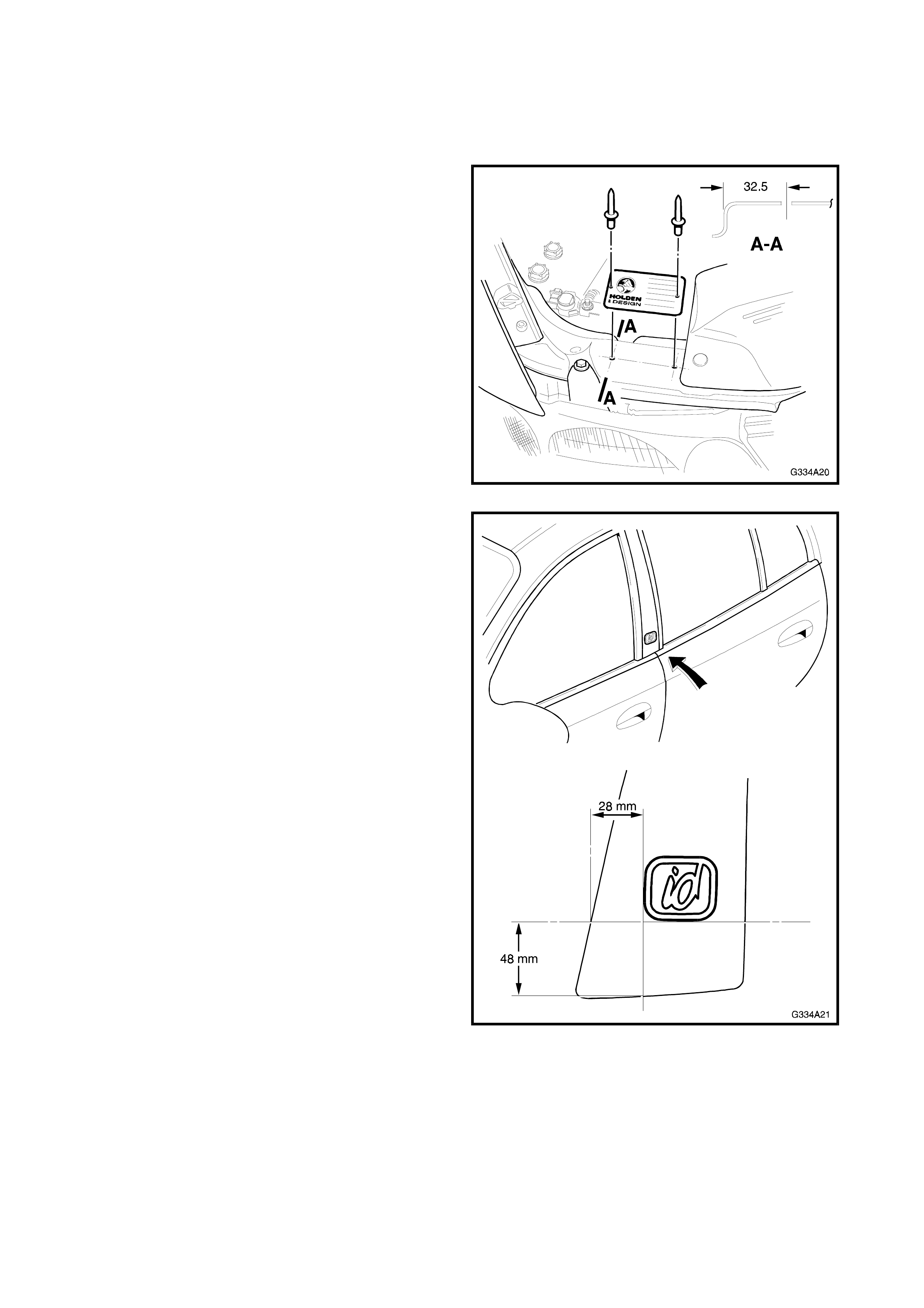
6. IDENTIFICATION & BADGING
Where a full Holden By Design id kit has been installed, a HBD identification plate is installed on the radiator
support panel under the bonnet. Holden By Design id labels are placed on each centre pillar.
Figure 4A-22 shows the location of the HBD
identification plate.
Drill 3 mm holes to the dimensions shown.
Figure 4A-21
Figure 4A-23 shows the location of the id label and
the positioning measurements on the centre pillar
trim.
Figure 4A-22
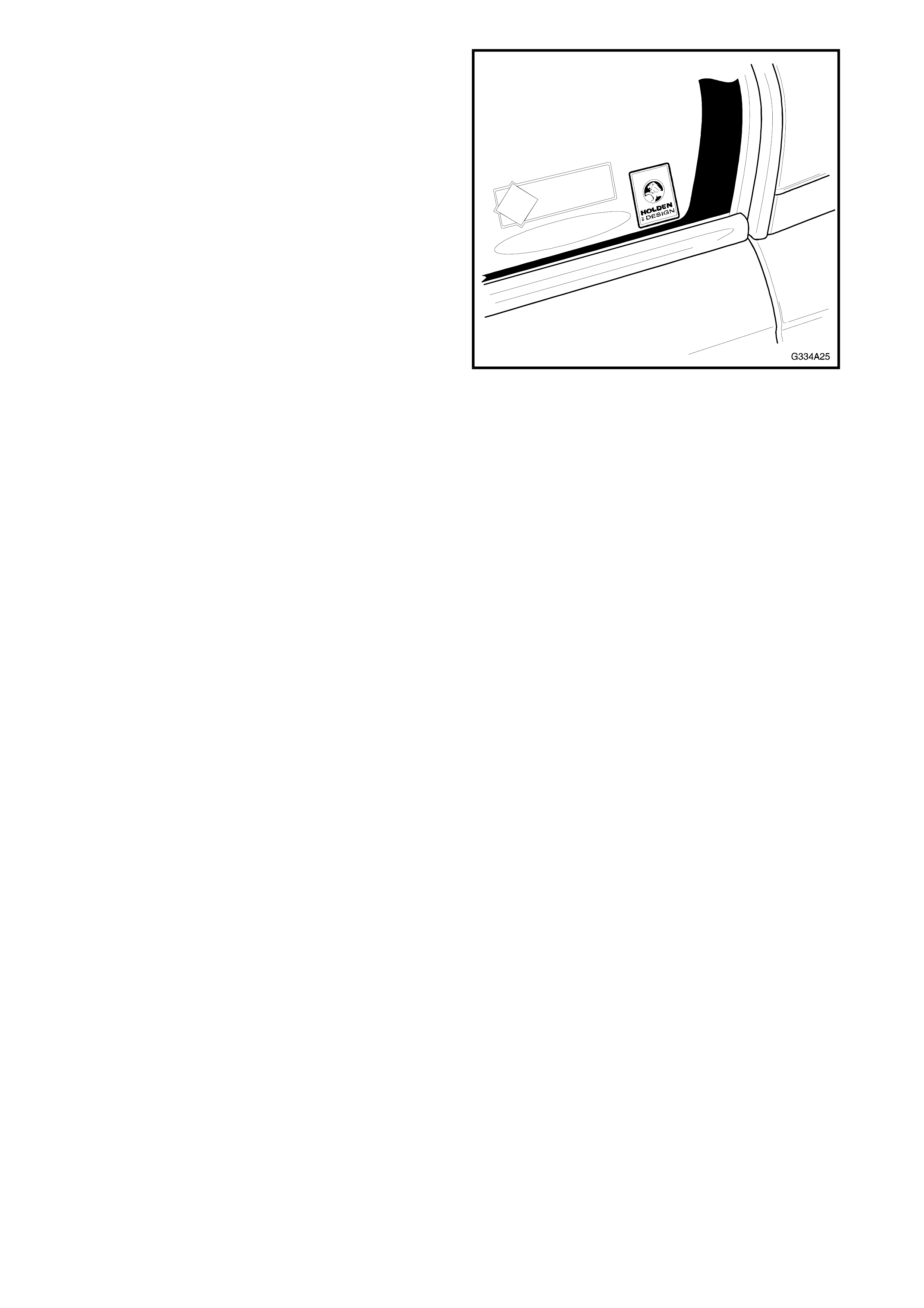
A Holden By Design decal is also affix ed to each rear
door fixed window as shown.
Figure 4A-23
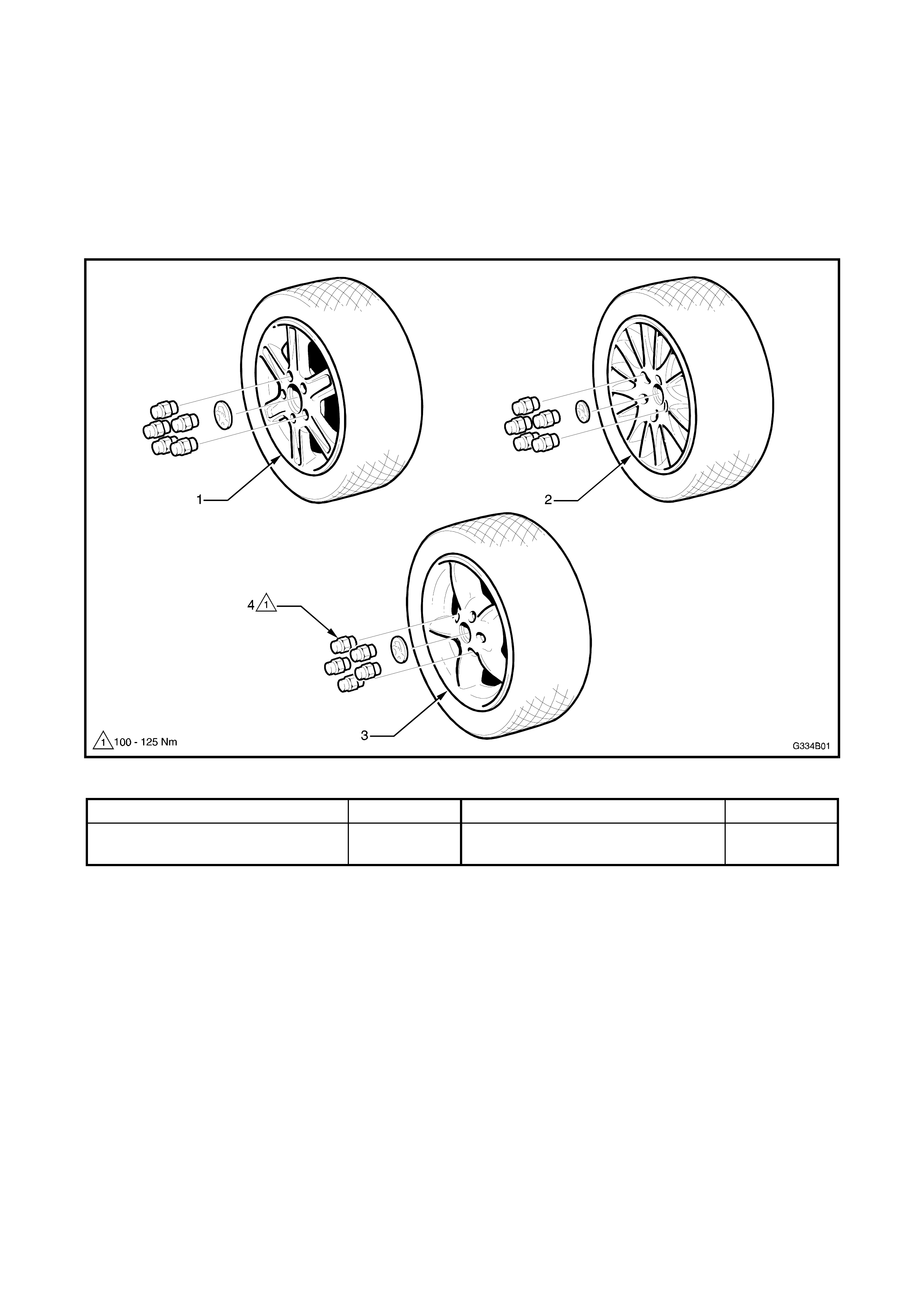
7. ALLOY WHEELS
Thr ee alloy wheel styles are available for Holden By Design VT Series Vehic les . Eac h has its own unique styling,
diameter and width.
While wheel nuts designed for use with alloy wheels are fitted, the wheel studs rem ain the s am e as standar d VT
Series vehicles. The standard steel rim spare wheel remains fitted.
This Section of the Holden By Design Service Information Supplement illustrates the wheel types available. For
the information required to service wheels for VT Series Vehicles, refer to Section 10, WHEELS & TYRES of
the VT Series I Service Information.
Figure 4A-24
1. T - Series 6-spoke alloy wheel 15” x 6.5” 3. RT - Series 5-spoke alloy wheel 17” x 8”
2. T - Series Multi-spoke alloy
wheel 16” x 7.5” 4. Alloy wheel nuts