SECTION 4C - VT SERIES SUNROOF
CAUTION:
This vehicle will be equipped with a Supplemental Restraint System (SRS). A SRS will consist of
either seat belt pre-tension ers and a driver’s air bag , seat belt pre-t ensioners and a driv er’s and front
passenger’s air bag s or seat belt pre-tensio ners, driver’s and fron t passenger’s air bags and left and
right hand side air bags. Depending upon the system fitted, refer to SAFETY PRECAUTIONS, Section
12M Supplemental Restraint System in the VT Series I Service Information, before performing any
service operation on or around any SRS components, the steering mechanism or wiring. Failure to
follow the SAFETY PRECAUTIONS could result in SRS deployment, resulting in possible personal
injury or unnecessary SRS system repairs.
CAUTION:
This v ehicle may be equipped w ith LPG ( Liquefied Pet roleum Gas). In th e interests of safet y, the LPG
fuel system should be isolated by turning 'OFF' the manual service valve and then draining the LPG
service lines, before any service work is carried out on the vehicle. Refer to the LPG leaflet included
with the Owner's Handbook for details or in the VT Series I Service Information for more specific
servicing information.
1. GENERAL INFORMATION
This Section of the Holden By Design Service Infor mation Supplem ent describes the ser vice procedures f or the
HBD sunroof available for VT Series Vehicles.
The sunroof is an electrically operated, two-way sliding and tilting type. It features a tinted glass panel with an
internal sliding sunshade and has a front edge wind deflector. The sunroof is operated by a rocker switch,
centrally located in the vehicle's headlining, forward of the sunroof aperture. A Sunroof Control Unit (SCU)
provides several pre-programmed functions and the facility to program an additional option.
PRE-PROGRAMMED FUNCTIONS
Soft Touch
By a single touch of the switch, the roof can be fully opened to the maxim um tilt position or the maximum slide
position.
Variable Tilt Position
The panel can be closed from tilt in four steps by continuously pressing the switch and releasing in the desired
position.
Jamming Protection (safety feature)
W hen closing the s unroof by soft touch or auto-c lose, the sunroof will autom atically re-open when it encounters
an obstacle. The roof will then attempt to re-close until the obstacle is removed.
Auto-Close Function
Three seconds after switching off the ignition the sunroof will close automatically. This can be prevented by
pressing the switch once within three seconds of the ignition being switched off.
One-Way Closing
This feature always closes the glass panel from above, assuring a flush fit of the panel.
OPTIONAL PROGRAMMABLE FUNCTION
Comfort Position In The Sliding Range
This feature allows a preset stopping position of the glass panel in the sliding range of the sunroof to be
programmed. The glass panel will stop at the preset position when opened via the soft touch operation.

1.1 GENERAL DESCRIPTION
GLASS PANEL MOVEMENT
Movement of the glass panel into the tilt and slide positions is controlled by the following functions.
Continuous Control
Press the switch longer than 0.3 second:
• Full control over the glass panel movement in the slide position.
• Releasing the switch will stop the glass panel movement.
• A full stop in maximum slide and closed position.
Four Steps Down Tilt Adjustment
Press the switch longer than 0.3 second:
• When closing the sunroof from maximum tilt position by pressing the switch continuously, the glass panel
will stop briefly in four intermediate positions.
• Releasing the switch will stop the glass panel movement.
• To continue the stepped operation, press the switch again.
One Touch Control
Press and release the switch within 0.3 second:
• Automatic glass panel movement towards full open or full closed position (slide and tilt).
• Anti-jamming protection while closing.
• The glass panel movement can be interrupted by pressing the switch.
Auto-Close
When the ignition is switched off, the glass panel will close after a three second delay:
• Anti-jamming protection while closing.
• Pressing the switch within three seconds after the ignition switch off will cancel auto-close.
One Way Closing
To ens ure correc t positioning of the glas s panel after c losing, it will always close from above, even when closed
from a slide position.
INTERIOR TRIM
Sunshade
Sunshade operation depends on glass panel movement as follows:
• Moving the glass panel to tilt position, the sunshade automatically opens to a vent position and can be
moved to full open position by hand.
• Moving the glass panel into slide position, the s unshade will move together and can also be fur ther opened
by hand.
• Closing the sunshade m ust be perfor med m anually. It can only be closed c ompletely when the glass panel
is in the closed position.
Wind Deflector
The wind deflector automatically raises when the glass panel m oves into sliding position and retracts when the
glass panel closes again.
The Holden By Design sunroof major components are shown in Fig. 4C-1.
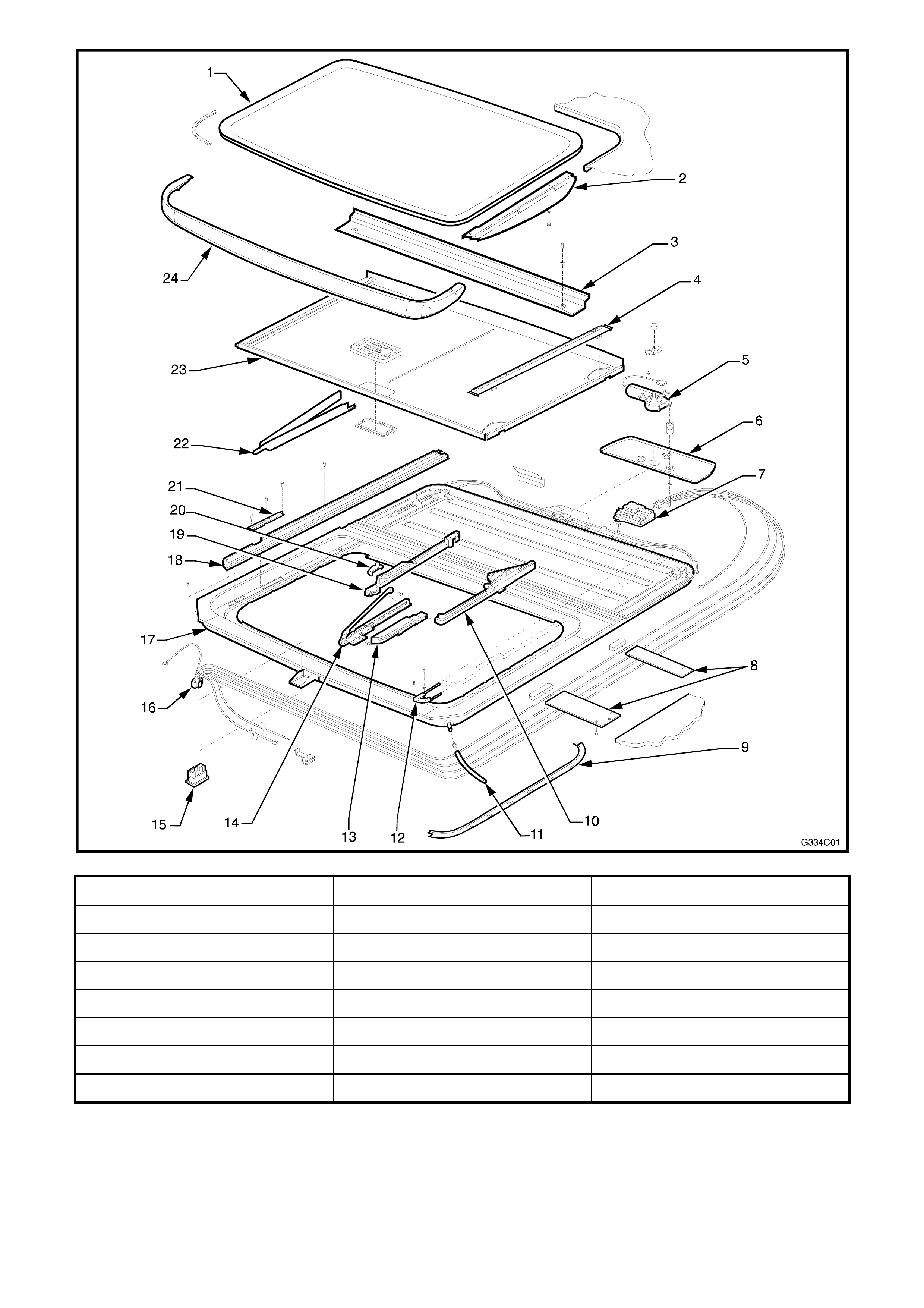
Figure 4C-1
1. Glass Panel 9. Side trimming 17. Frame
2. Exterior cover 10. Rear driving slide 18. Guide rail
3. Drain Channel 11. Drain tube 19. Rear basic slide
4. Sunshade guide 12. Retraction mechanism 20. Blocking catch
5. Drive motor 13. Front driving slide 21. Locator
6. Drive motor cover 14. Front basic slide 22. Mechanism cover
7. Sunroof control unit (SCU) 15. Switch 23. Sunshade
8. Side support bracket 16. Harness 24. Wind deflector

2. SERVICE OPERATIONS
The following service operations for the Holden By Design sunroof are those that can be performed by the
general service technician. The procedure for the removal and installation of the sunroof assembly has
deliberately been omitted due to the skills and special tools required, which would be beyond the scope of the
general repair technician. Also, as the sunroof assembly is chemically bonded to the vehicle’s roof panel,
damage to the sunroof and roof panel will result if rem oval is perf orm ed, necessitating s unroof replac ement and
roof panel repair.
NOTE: W here a sunroof is fitted, a new headlining is created using pieces of the original headlining and a new
sheet of c loth. The headlining is then installed with adhesive. Rem oval m ay damage the headlining and extr em e
care is required.
If assist ance is required in the servic ing or installation of the s unroof as sembly, contact the authoris ed Hollandia
sunroof specialist in your area or contact Hollandia Sunroofs Australasia on (02) 9540 4811.
2.1 DRIVE MOTOR
REMOVE
1. Remove or lower the rear of the headlining to gain access to the drive motor cover.
2. Remove the cover. The drive motor will lower with the cover.
3. Disconnect the drive motor wiring connector from the sunroof control unit.
INSTALL
1. Connect the drive motor wiring connector to the sunroof control unit.
2. Check the drive motor for correct operation in both directions, refer to 3.2 TESTING ELECTRICAL
COMPONENTS in this Section.
3. Install the drive motor and drive motor cover.
4. Check the sunroof for correct operation.
5. Refit the headlining.
2.2 SUNROOF CONTROL UNIT (SCU)
REMOVE
1. Remove or lower the rear of the headlining to gain
access to the drive motor cover.
2. Utilising a manual c rank , vent (tilt) the glass panel
to the fully open position.
3. Remove the LH mechanism cover.
4. Utilising the manual crank, close the glass panel
1.5 revolutions.
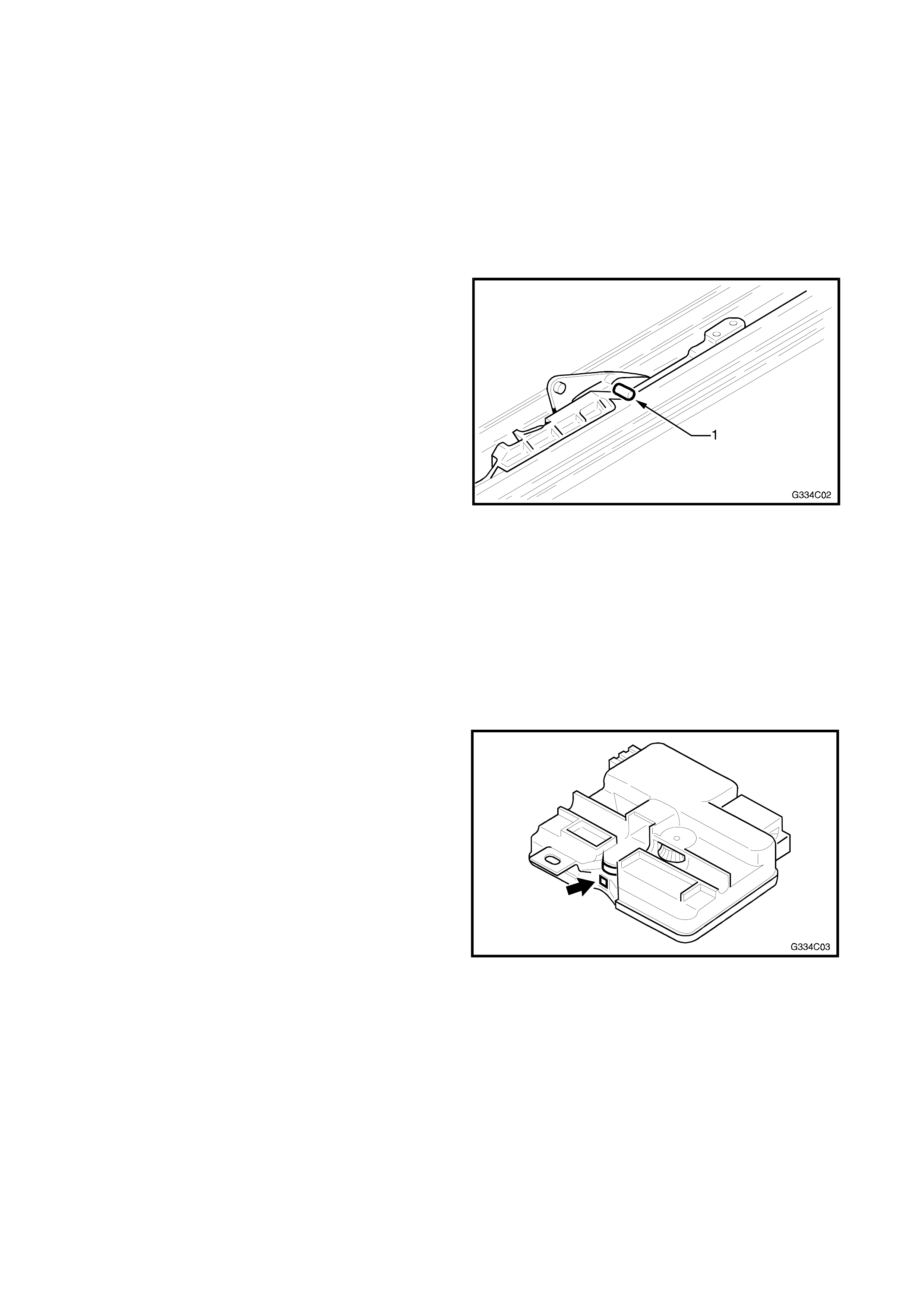
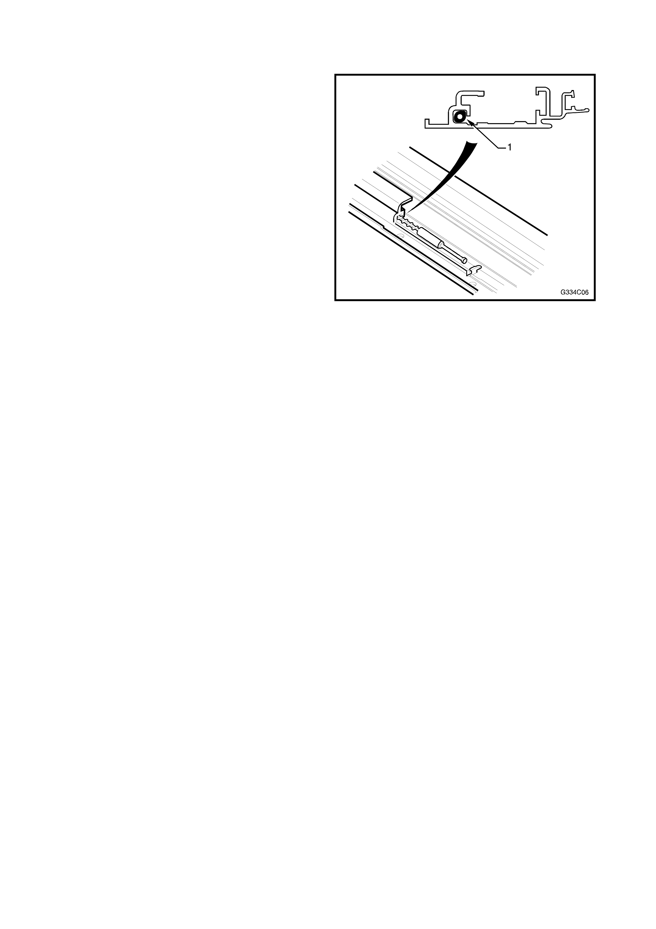
5. Place a pin in each 2.5 mm br ass hole as shown.
Venting the glass panel, turn the crank quarter of
a turn forward. The pin (1) stops the mechanism
at the desired location.
Figure 4C-2
6. Remove the motor cover carefully. The drive
motor will lower with the cover.
7. Disconnect the drive motor wiring from the SCU
and remove the drive motor.
8. Disconnect the wiring harness from the SCU.
9. Remove the screw securing the SCU and lower
the front of the SCU to clear the cable. Slide the
SCU back and remove.
INSTALL
1. Synchronise the SCU for correct alignment of the
spots on the gearwheel in the view finders as
shown and described in 2.3 SYNCRONISATION
OF SCU in this Section.
2. Lowering the front of the SCU for cable
clearance, slide it forward and engage the lip of
the cable plate in the SCU slot. Straighten the
SCU horizontally and tighten the screw.
3. Connect both wiring connectors to the SCU and
install the drive motor and cover.
4. Check the sunroof for correct operation.
5. Install the headlining.
6. Install the LH mechanism cover. Figure 4C-3

2.3 SYNCHRONISATION OF SCU
1. Remove the SCU as described in 2.2 SUNROOF CONTROL UNIT (SCU) in this Section.
2. Align the two spots in the view finders. Turn the exposed black cable gear, mounted in the top centre of the
SCU. When each spot appears directly in line with the other, top to bottom, stop.
NOTE: If the spots are not aligned, turn the top mount cable gear until each spot appears aligned over one
another in the view finders. Refer Fig. 4C-3.
3. Install the SCU and motor
2.4 DRIVE CABLES
REMOVE
1. Remove the mechanism covers, glass panel,
drain channel, wind deflector, sunshade and
adjustment bracket.
2. Place the mechanism in the closed position.
3. Remove the motor and SCU as described in 2.2
SUNROOF CONTROL UNIT (SCU) in this
Section.
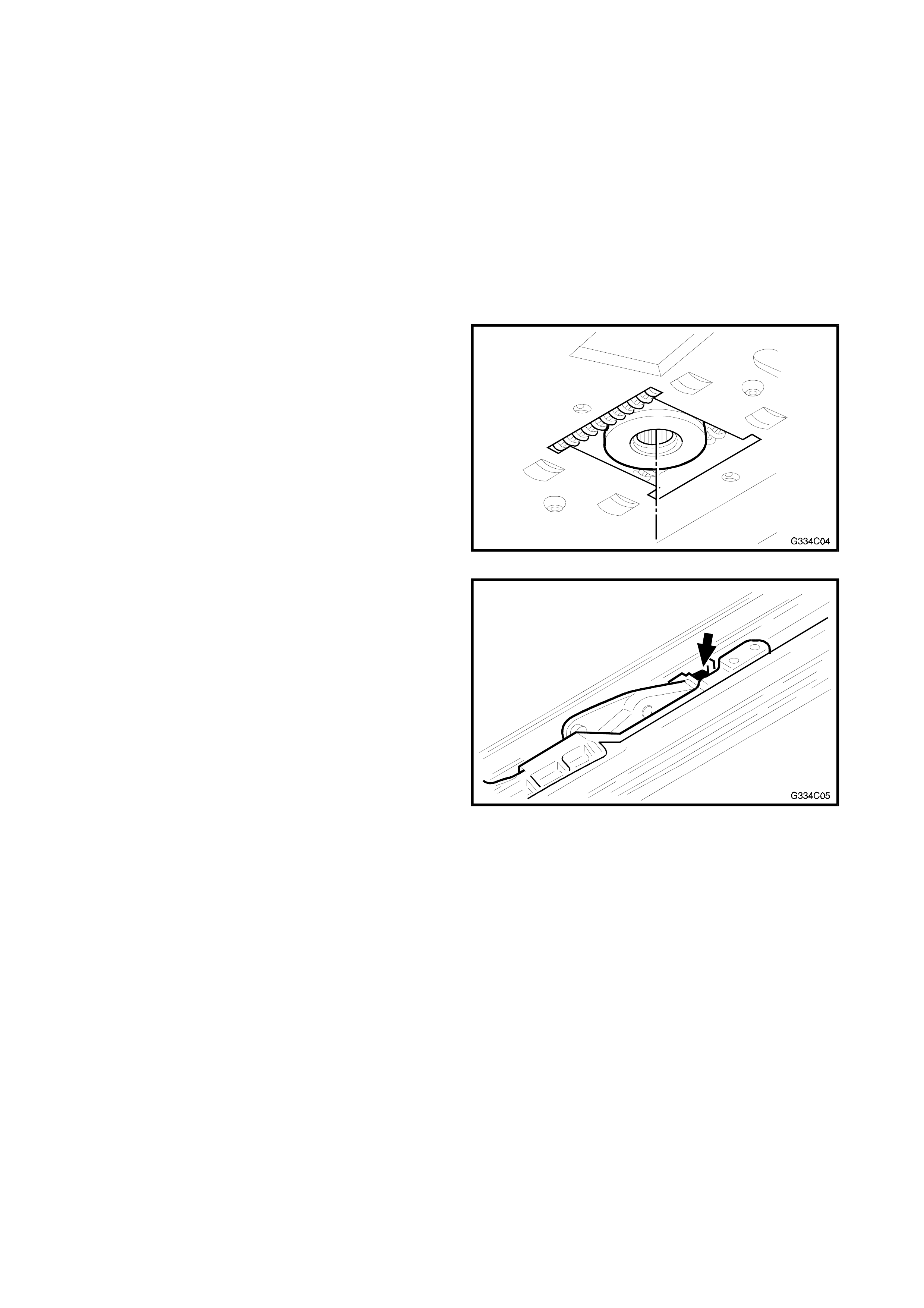
4. Remove the gearwheel housing by removing the
two screws.
5. Remo ve the gearwheel by inserting a sc r ewdriver.
Push it forward and the gearwheel drops down.
Figure 4C-4
6. Place a screwdriver in the mechanism as
indicated in Fig. 4C-5. Push this mechanism
rearward into the slide position. Continue pushing
backwards by placing a hand on the front of the
mechanism. Three locating screws become
accessible.
Figure 4C-5
7. Remove the locating screws, being careful to
remember the positioning of the screws and the
blocking catch.
8. Pull the mechanism all the way forward.
9. Push the mechanism into the tilt position as in
Step 6, taking care not to inadvertently dislodge
the mec hanism . Keep the front of the mechanis m
down.
10. Remove the front screw and slide the retraction
mechanism forward. Do not it take out.
11. Slide the mechanism in the tilt position further
forward.
12. Remove the Torx screw which connects the
curve-on panel to the adjustment bracket.
Remove the aluminium curve-on panel from the
long lever. Pivot the adjustment bracket forward.
13. Lift the cable out and pull it forward, out from the
guide rail track.
INSTALL
1. Inspect the new cable for correct length. Oil the
cable using Applied Chemicals Tefoil +PTFE, Part
No. 8-830, and slide it into the rail.
NOTE: Ensure the oval shaped copper head of the
cable (1) seats firm ly and diagonally across the guide
channel.
Figure 4C-6
2. To check that cable is positioned correctly, grasp
the long lever in the tilt position with one hand, the
pivoting adjustm ent brack et in the other hand and
slide backwards, it should slide into place (if
blocked, turn cable slightly to re-seat copper oval
head properly).
3. Pivot the arm of the adjustment bracket back
down into place. Slide the curve-on panel back
into place over the cap on the long lever and
install the Torx screw.
4. While holding the adjustment bracket stable, push
the mechanism into the slide position as in
Step 6 -Remove.
NOTE: If the mechanism stops after approximately
100 mm preventing a full rearward positioning, you
failed to hold the adjustment bracket stable, repeat
this step.
5. Slide the whole mechanism rearwards to allow
installation of the locator.
6. Slide the retraction mechanism rearwards, install
the screw and locator.
7. To replace the other cable, repeat the procedure
from Step 7 - Remove.
8. Slide both LH & RH mechanisms to the front
position.
9. Push the LH & RH mechanisms to the closed
position. Insert a pin in each 2.5 mm brass hole.
Slide the mechanism forward until the pin stops
the mechanism’s movement at the desired
location. Refer to Fig. 4C-2.

10. Install the new gearwheel, ensuring that it is
centred in the hole in the drive motor bracket.
Note that the core or centre of the gear has
splines. The splines do not extend completely to
one side of the gear’s inner c ore. This is the down
(bottom) side for mounting. Refer to Fig. 4C-4.
11. Install the new gearwheel housing.
12. Install the SCU and motor as described 2.2
SUNROOF CONTROL UNIT (SCU) in this
Section.
13. Inspect the sunroof for correct electrical and
mechanical function.
14. Fit the headlining.
15. Install the adjustment bracket, sunshade, drain
channel, glass panel, wind deflector and
mechanism covers.
16. Check the sunroof for correct operation.

2.5 TIMING OF DRIVE CABLES
1. Fully tilt the panel.
2. Remove the LH & RH mechanism covers.
3. Fully close the panel.
4. Remove the motor and SCU as described in 2.2 SUNROOF CONTROL UNIT (SCU) in this Section.
5. Remove the gearwheel housing by removing the two screws.
6. Remove gearwheel by inserting a screwdriver, push forward and the gearwheel drops down. Refer to
Fig. 4C-4.
7. Push the LH & RH mechanisms to the closed position. Place a pin in each 2.5 mm brass hole. Slide the
mec hanis m for ward until the pin stops the mec hanism’s movement at the desir ed loc ation. Ref er to F ig. 4C-
2.
8. Install the new gearwheel, ensuring that it is centred in the hole in the drive motor bracket.
NOTE: The core or centre of the gear has splines. The splines do not extend completely to one side of the
gear’s inner core. This is the down (bottom) side for mounting. Refer Fig. 4C-4.
9. Install the new gearwheel housing.
10. Install the SCU and motor as described in 2.2 SUNROOF CONTROL UNIT (SCU) in this Section.
11. Inspect the sunroof for correct electrical and mechanical function.
12. Fit the headlining.
13. Install the LH mechanism cover.
14. Check the sunroof for correct operation.

2.6 ADJUSTMENT BRACKET
REMOVE
1. Remove the glass panel as described in 2.7 GLASS PANEL in this Section.
2. Remove the adjustment bracket from the glass panel by removing the front retaining clip and Torx screw.
The adjustment bracket is moved sideways from the long lever in the rear and the mechanism in the front.
INSTALL
1. Installation is the reverse of the removal procedure.
2. Check the sunroof for correct operation.
2.7 GLASS PANEL
REMOVE
1. Place the glass panel in the tilt position.
2. Remove the two front screws and two centre
screws and remove the glass panel.
INSTALL AND ADJUST
1. Slide the mechanism to the tilt position.
2. Inspect the rubber seal and glass panel for
damage. Insert the glass panel.
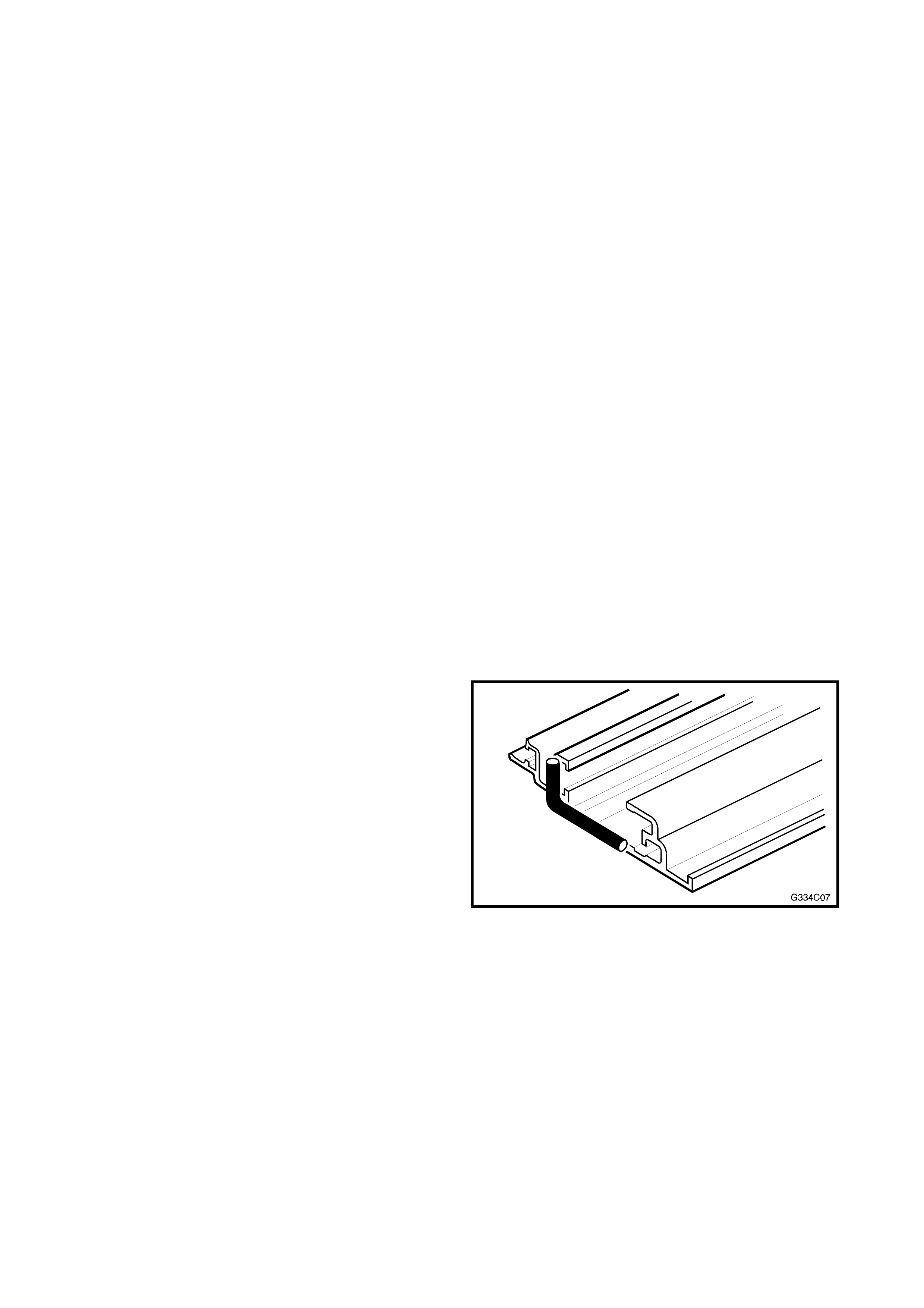
3. Place the height adjustm ent curve (1), which is at
the rear of the glass panel, over the mechanism.
Place the vertical front lips on the panel between
the RH & LH mechanisms.
Figure 4C-7
4. Lift the mechanism mounting bracket from the
inside and install the two front and two centre
screws, leaving the four screws loose.
5. Put the glass panel in closed position.
6. Adjust the glass panel to the front. Using a
business card, for example, check the tension of
the seal against the trim ring at the rear.
7. Tighten both centre screws.
8. Adjust the height at the front and tighten front
screws.
9. Adj us t the height at the rear by loosening the Torx
screws of the adjustment curve. Adjust the glass
level with roof panel and tighten screws. Refer
Fig. 4C-7.
GLASS PANEL HEIGHT
ADJUSTING SCREWS
TIGHTENING TORQUE 3.5 Nm
10. Check the operation of the mechanism and
adjustm ents. Repeat Steps 6 to 9 to r e-adjust the
glass panel if necessary.

2.8 SEAL
REMOVE
1. Remove the LH &RH mechanism covers, glass panel and exterior covers.
2. Remove the seal from the glass panel.
3. Remove all foreign debris from around the glass frame.
INSTALL
1. Install the new seal, beginning at the front centre of the glass frame retaining channel.
2. Using your thumbs, insert the seal with enough pressure to ensure that the seal is seated flush.
3. Trim the seal length. Leave approximately 6 mm extra then work it into retaining channel.
4. Install the glass panel, refer to 2.7 GLASS PANEL in this Section.
5. Install the LH and RH mechanism cover.
6. Check the sunroof for correct operation
2.9 SEAL - ADJUST
The correct positioning of the glass panel should
result in the seal firmly contacting the EPDM trim ring
of the sunroof opening. If the panel fits properly, but
gaps remain between seal and trim ring, it can be
corrected as follows.
1. Adjust the glass panel correctly against the rear of
the trim prof ile, refer to 2.7 GLASS PANEL in this
Section.
2. With a grease pencil or similar, mark the
boundaries of insufficient contact on the panel at
the front.
3. Remove the glass panel, refer to 2.7 GLASS
PANEL in this Section.
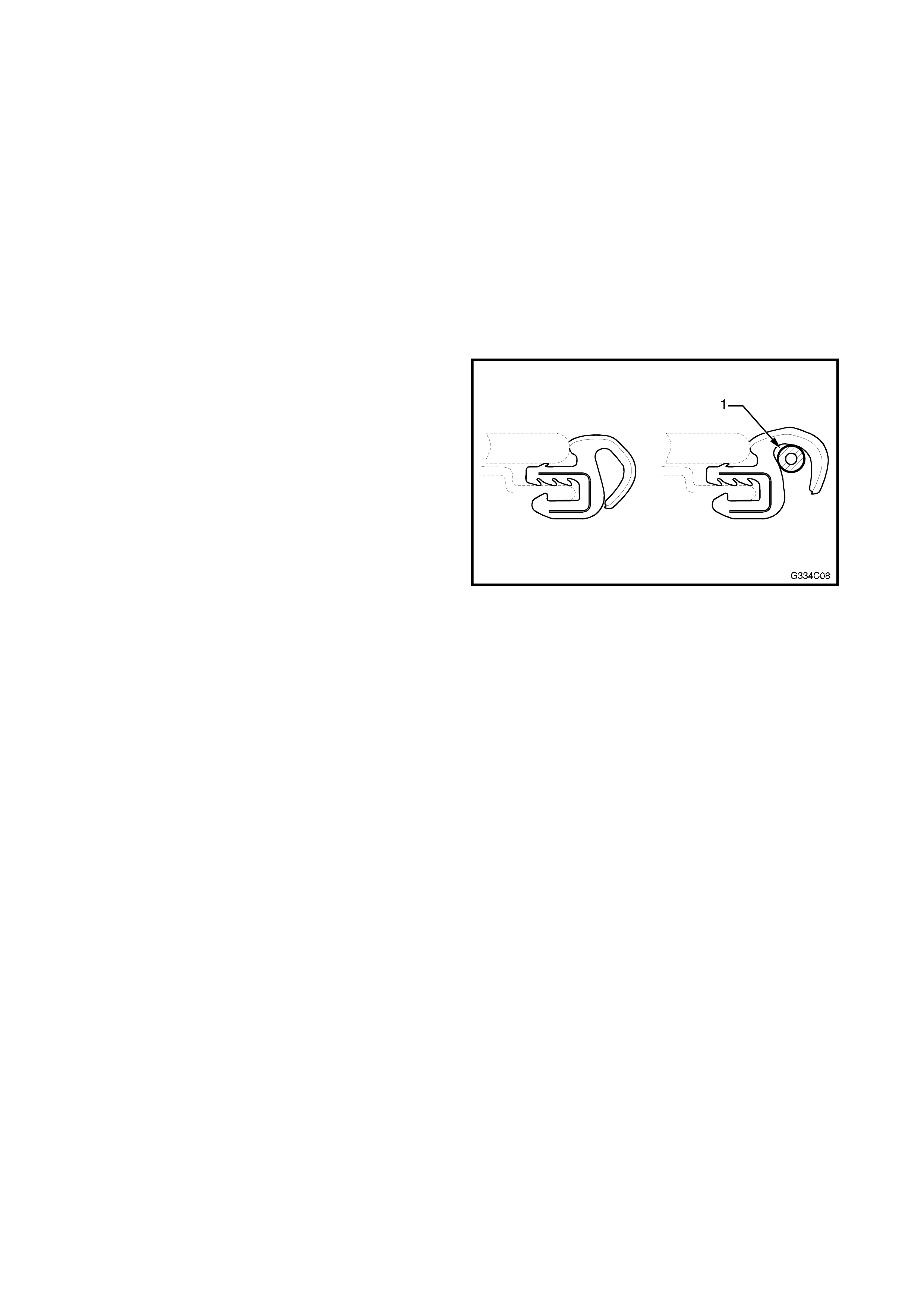
4. In the areas m arked, insert a spac er (1) inside the
rubber seal as shown. Use a vinyl tube with outer
diameter of 3 mm for spacer material.
Figure 4C-8
5. Glue the spacer to the seal with super glue.
6. Install the glass panel and adjust, refer to 2.7
GLASS PANEL in this Section.

2.10 RE TRACTION MECHANISM
REMOVE
1. Retract the glass panel completely.
2. Remove the wind deflector mounting nuts and remove the wind deflector.
3. Remove the two screws and take the retraction mechanism forwards out of the rail.
INSTALL
1. Install the new retraction mechanism in the rail.
2. Install the wind deflector.
3. Check the sunroof for correct operation.
2.11 GUIDE RAIL MECHANISM
REMOVE
1. Remove the LH & RH mechanism covers, glass
panel, drain channel, wind deflector and
sunshade.
2. Tilt the mechanism completely.
3. Fully retract the mechanism.
4. Remove the locator, retraction mechanism and
rail scr ews, noting the length and position of each
screw.
5. Remove the wind deflector mounting nuts.
6. Slide the rail sideways to unlock, then lif t the front
up.
7. With the rail front up, grasp the retractor
mechanism and remove.
8. Fully close the mechanism.
9. Lift and pull the rail slowly forward over the
mechanism As soon as the front of drive cable
appears at end of guide, lift out the c able. Pull the
mechanism carefully forward and lift out.
INSTALL
1. Inspect the new replacement mechanism for
cleanliness and completeness.
2. Slide the mechanism rearward, out of the rail for
cable installation access.
3. Install the cable, then push the mechanism
forward on the rail (maintain access to rear rail
area).
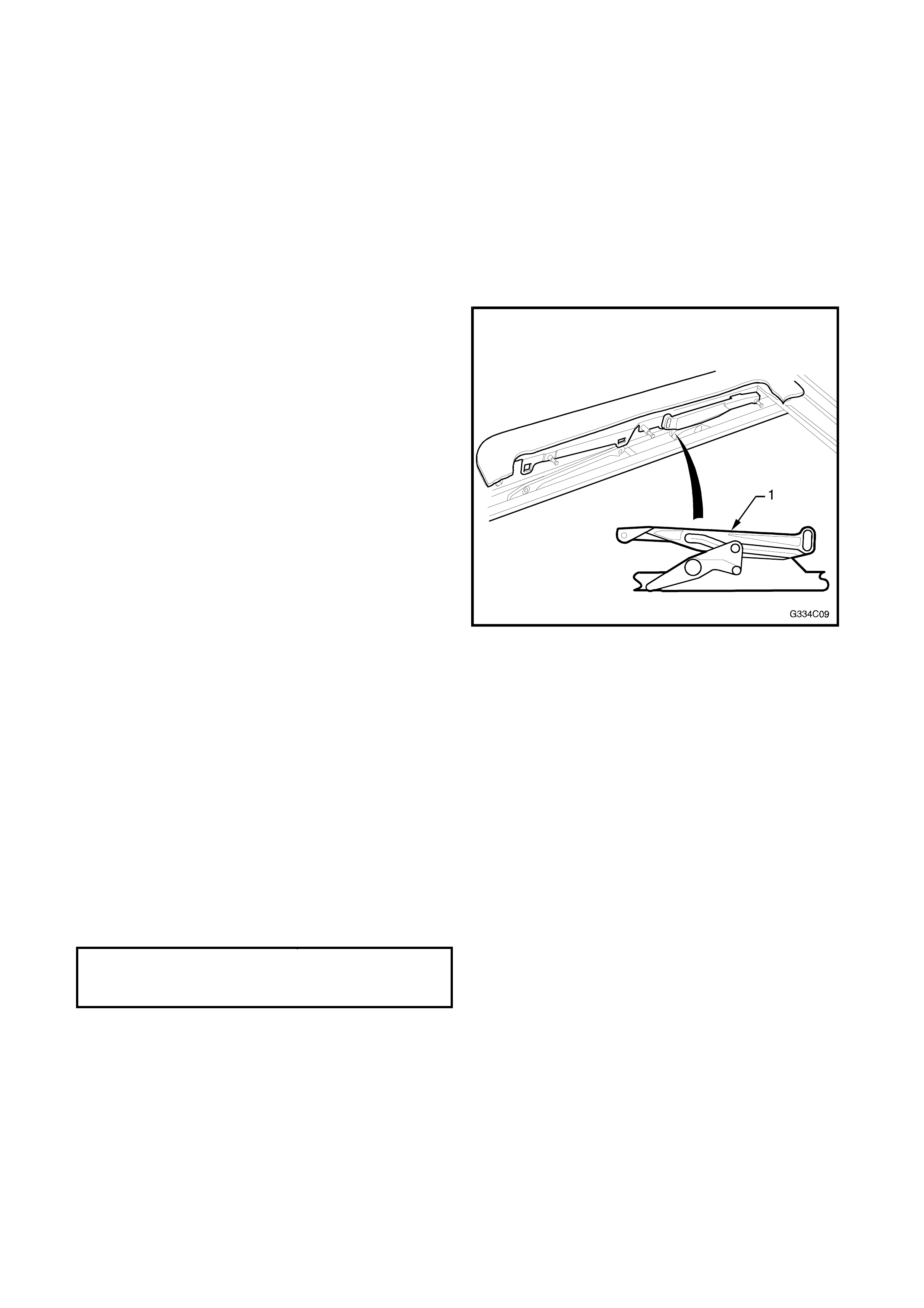
4. Apply a bead of sealer as shown.
Figure 4C-9
5. Slide the rail rearward, over the mechanism and
drive cable, while holding the front of the
mechanism in place.

6. As soon as the rail is fully extended rearward,
lower the front to the frame and push the rail
rearward into the rail stop. Align the screw holes
for correct positioning.
7. Retract the mechanism totally.
8. Lift the front of the rail to reinstall the retractor
mechanism.
9. Lower the rail and push it inboard until it locks in
place.
10. Starting at the front, install the rail screws.
NOTE: Ensure the screws are installed in their correct
holes.
9. Replace the wind deflector mounting nuts loosely.
10. Tilt the mechanism completely.
11. Inspect for correct mechanical function of the
mechanism.
12. Install the sunshade, drain channel, panel and
wind deflector.
13. Inspect the function of the sunroof, reinstall the
LH and RH mechanism covers.

2.12 BLOCKING CATCH
REMOVE
1. Remove the LH & RH mechanism covers and glass panel.
2. Fully retract the mechanism.
3. Remove the locator.
4. Fully tilt the mechanism.
5. Remove the blocking catch by lifting it out.
6. Clean out broken blocking catch debris if required.
INSTALL
1. Install the new blocking catch in the mechanism. Insert the circular eye stud into the mechanism making
sure the second smaller stud falls cleanly into the mechanism slot.
2. Fully retract the mechanism.
3. Install the locator.
4. Check for correct mechanical operation.
5. Install the glass panel and LH & RH mechanism covers.

2.13 DRAIN TUBES
Drain tubes as shown in Fig. 4C-10 are fitted to each
corner of the sunroof c assette and are routed thr ough
each A and C pillar. The drain tubes allow water to
drain from the sunroof cassette to the ground.
REMOVE
Front
1. Remove the A pillar upper and lower trims,
sunvisor and caref ully lower the relevant co rner of
the headlining. Refer to Sect ion 1A8, HEADL ING
& REAR END TRIM of the VT Series I Service
Information.
2. Disconnect the drain tube from the sunroof
cassette.
3. Remove the grommet from the upper inner side
panel.
4. Pull the tubing through the upper side panel and
remove.
Rear
1. Remove the headlining rear upper trim and C
pillar upper trim and carefully lower the relevant
corner of the headlining. Refer to Section 1A8,
HEADLING & REAR END TRIM of the VT Series
I Service Information.
2. Partially remove the relevant rear compartment
side trim and pull the drain tube through the
grommet in the quarter panel.
3. From within the passenger compartment,
disconnect the drain tube from the sunroof
cassette.
4. Pull the drain tube through the pillar and remove.
INSTALL
1. Installation is the reverse of removal
NOTE: Ensure the drain tubes are c lear from dirt and
debris and that they are free from kinks.
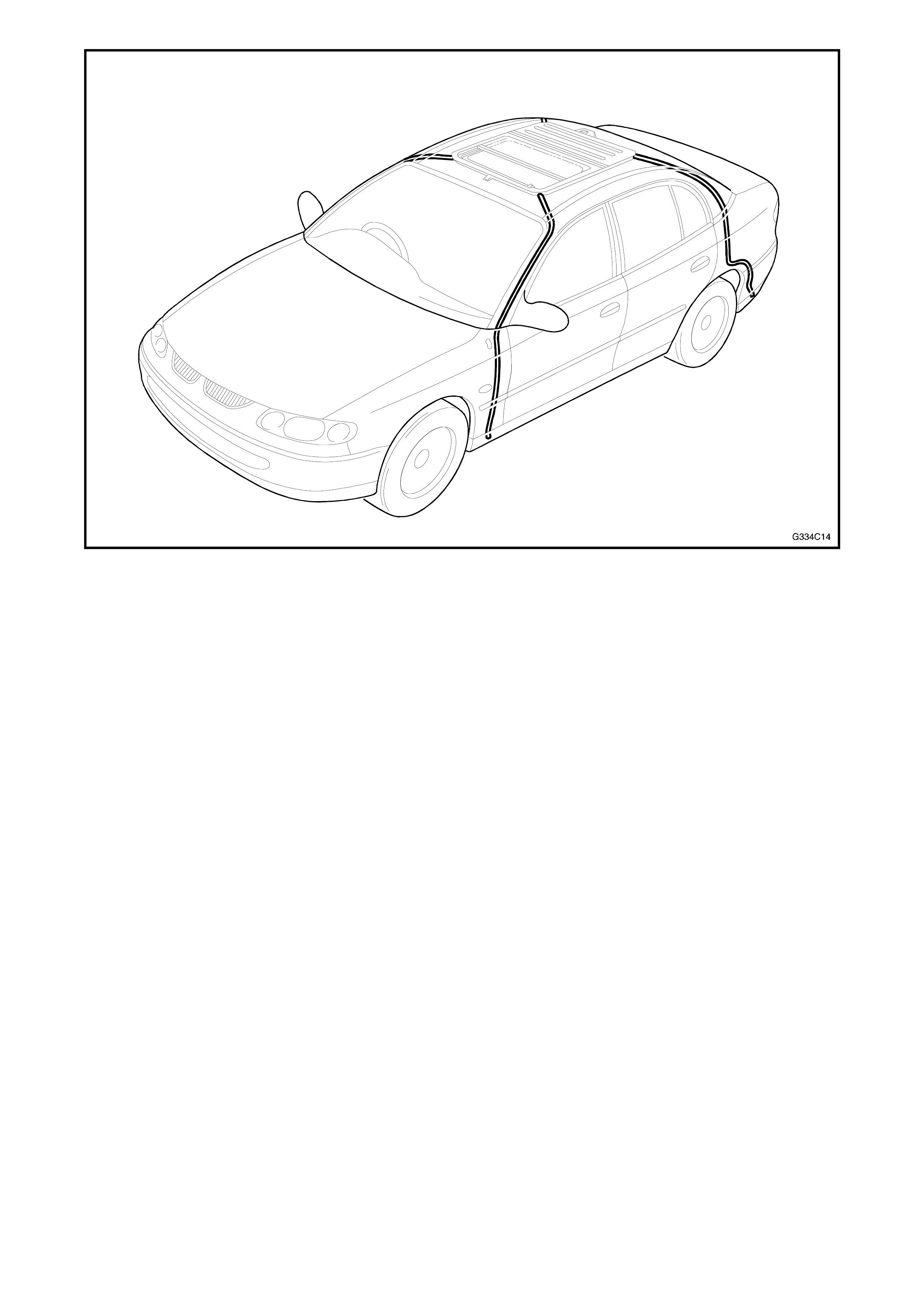
Figure 4C-10

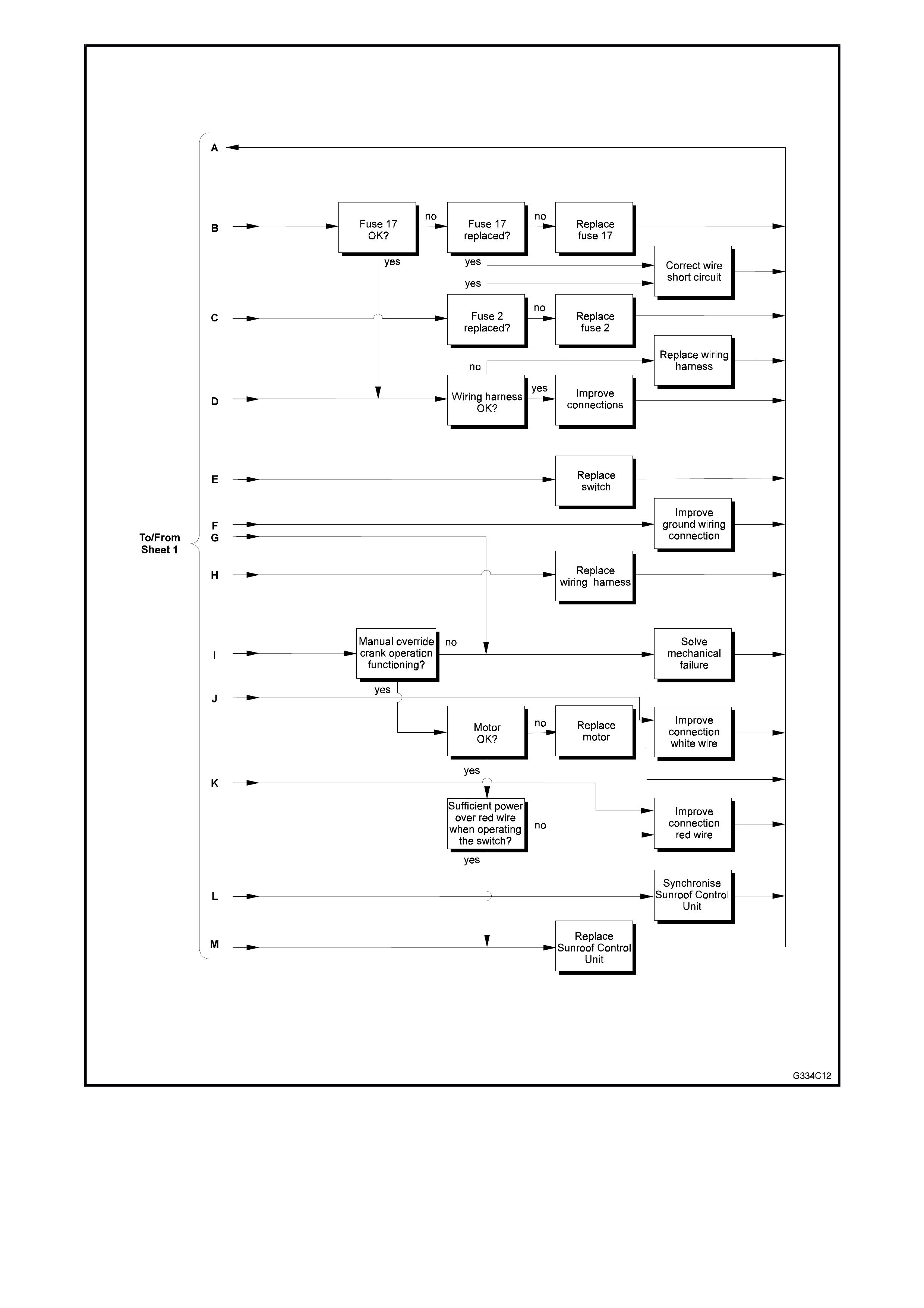
3. DIAGNOSIS
3.1 FAULT DIAGNOSTIC CHARTS
The fault Diagnostic Charts included in this section list the possible causes and provide a solution with a
reference to a particular paragraph to resolve the fault.
MECHANICAL FAILURES
PROBLEM POSSIBLE CAUSE SOLUTION
While c ycling the panel from tilt t o close i t
begins sl i di ng rearward. Blocking cat ch is brok en. Replace bloc king cat ch, refer to 2.12
BLOCKING CATCH in this Section.
While c ycling ful l y open panel forward, it
begins ti l t i ng under roof ski n. Blocking cat ch is brok en. Replace bloc king cat ch, refer to 2.12
BLOCKING CATCH in this Section.
Glass panel i s misaligned si de to side. Timi ng of dri ve c abl es incorrec t. Retim e dri ve c abl es, refer t o 2.5 TIMING OF
DRIVE CABLES in this Section.
Glass panel sliding too slowly
(with 13.5 V power supply the panel should
not take more than 7 seconds to cycl e f rom
full ret raction to closure).
Weak bat tery.
Misaligned panel creating drag or fri ction.
Faulty drive m otor.
Dirty mechanism .
Charge or replace.
Retim e dri ve c abl es, refer t o 2.5 TIMING OF
DRIVE CABLES in this Section.
Test the dri ve motor as detailed in 3. 3
TESTING ELECTRICAL COMPONENTS in
this S e ction. If necessary, repl ace drive
motor, refer to 2.1 DRIVE MOTOR in this
Section.
Clean and oil the mechani sm using Tefoil
+PTFE (availabl e f rom Appli ed Chemic al s)
or replace if necessary, refer to 2.11 GUIDE
RAIL MECHANISM in this Section.
Glass panel stopping prematurely. Sunroof control unit adj usted improperly.
Obstac l e i n mechani sm or gui de t rack.
Synchronis e sunroof control unit, refer to
2.3 SYNCHRONISATION OF SCU i n this
Section.
Find object and remove.
Sunshade fai l s to open when glass panel i s
opened to tilt posit i on. Retraction m echanism broken. Replace retraction mechanism, refer to
2.10 RETRACTI ON MECHANISM in thi s
Section.
RATTLING NOISES
PROBLEM POSSIBLE CAUSE SOLUTION
Drain channel rat tles. Inspec t for ins ul ator tape between drain
channel and mechanis m. Add insulator tape.
Rattles from side(s) Mounting brac ket screws loose Tighten s crews or repositi on mounting
brackets.
Rattli ng i n dri ve motor area. Cover plate on drive motor has l oose
screws. Tighten cover plat e screws.
WIND NOISES
PROBLEM POSSIBLE CAUSE SOLUTION
Panel cl osed, excessi ve wind nois e . Glass panel seal not ti ght to trim ring.
Blocking cat ch broken.
Correct glass panel adjustment, ref e r t o 2.7
GLASS PANEL in this Section.
Replace bloc king cat ch, refer to
2.12 BLOCKING CATCH in thi s Section.
WATER LEAKS
PROBLEM POSSIBLE CAUSE SOLUTION
Water c oming t hrough panel openi ng area. Bloc ked drain tubes .
Misaligned or k i nked drain tubes .
Housing frame dis t orted, seal to rail
disconnected.
Rear rail brack et has broken seal.
Inspec t drai n tubes cl ean openi ng, blow out
tubes.
Ensure that drain tubes are correctl y rout ed
through front and rear pillars .
Correct f rame curvature if nec essary res eal
rail to frame.
Reseal at rear rai l seal point, refer to
2.11 GUIDE RAIL MECHANISM in this
Section.
Headlining wet in front . Either f rame seam has i ncorrect seal. Reseal at seam.
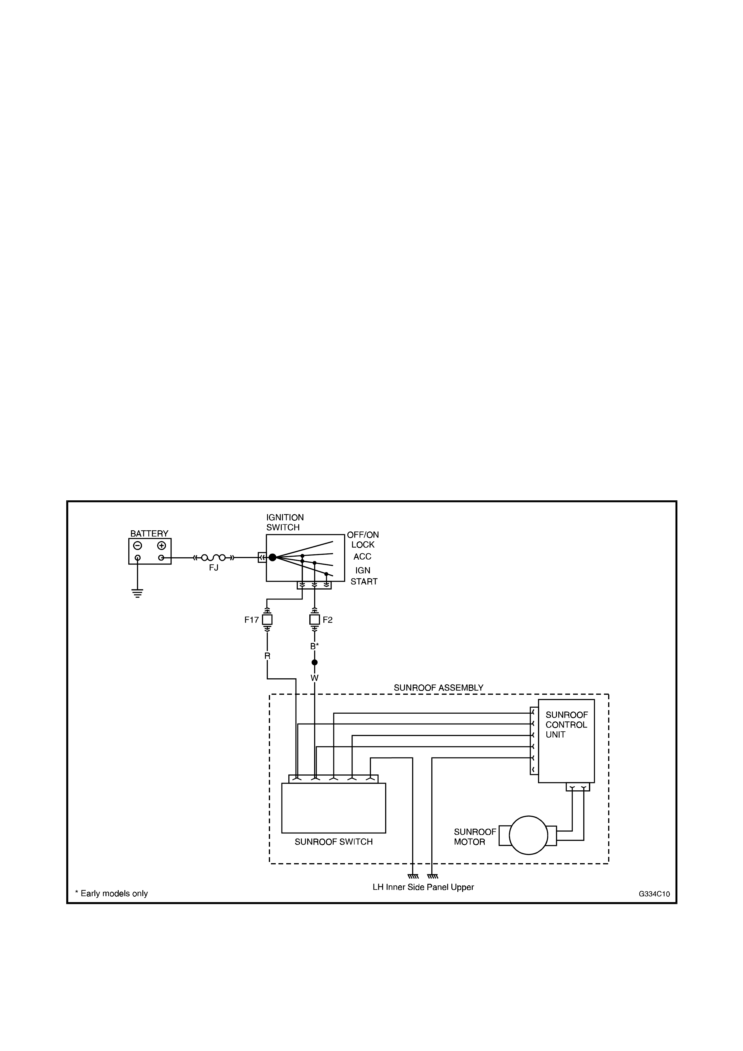
3.2 TESTING ELECTRICAL COMPONENTS
Ensure that during testing electrical components, the sunroof is connected to a power source supplying 12 to
14 V. If the Sunroof is installed, the battery needs to be connected and operable. During testing, the ignition/
accessory switch should be on. This test can be accomplished with a test light or multimeter and by using the
wiring schematic in Fig. 4C-11 as a guide.
NOTE: Harness and drive motor inspection requires at least part of the headlining to be removed.
FUSES
Visually inspect the fuses for damage and replace as required.
WIRING HARNESS
Check for correct power supply on the Red and White (Black early models) wires. Inspect for broken or
damaged wires. Inspect for secure connection to the SCU.
SWITCH
Inspect for correct power supply to the sunroof operating switch, accomplished by using a test light on the
connector at the switch bracket. Operate the switch connector to assure movement in front and rear sliding
positions.
DRIVE MOTOR
Disconnect the drive motor wire (Green/Black) from the sunroof control unit. Remove the drive motor. Using a
double wire of sufficient length, connect direct to the battery.
Check the drive motor for correct operation in both directions. This is accomplished by reversing the connection
of the double wire.
The drive motor has an in-built thermal cut-out device that automatically sw itches the drive motor off during
periods of overload. After a cooling down period, the drive motor will function properly.
WIRING SCHEMATIC
Figure 4C-11
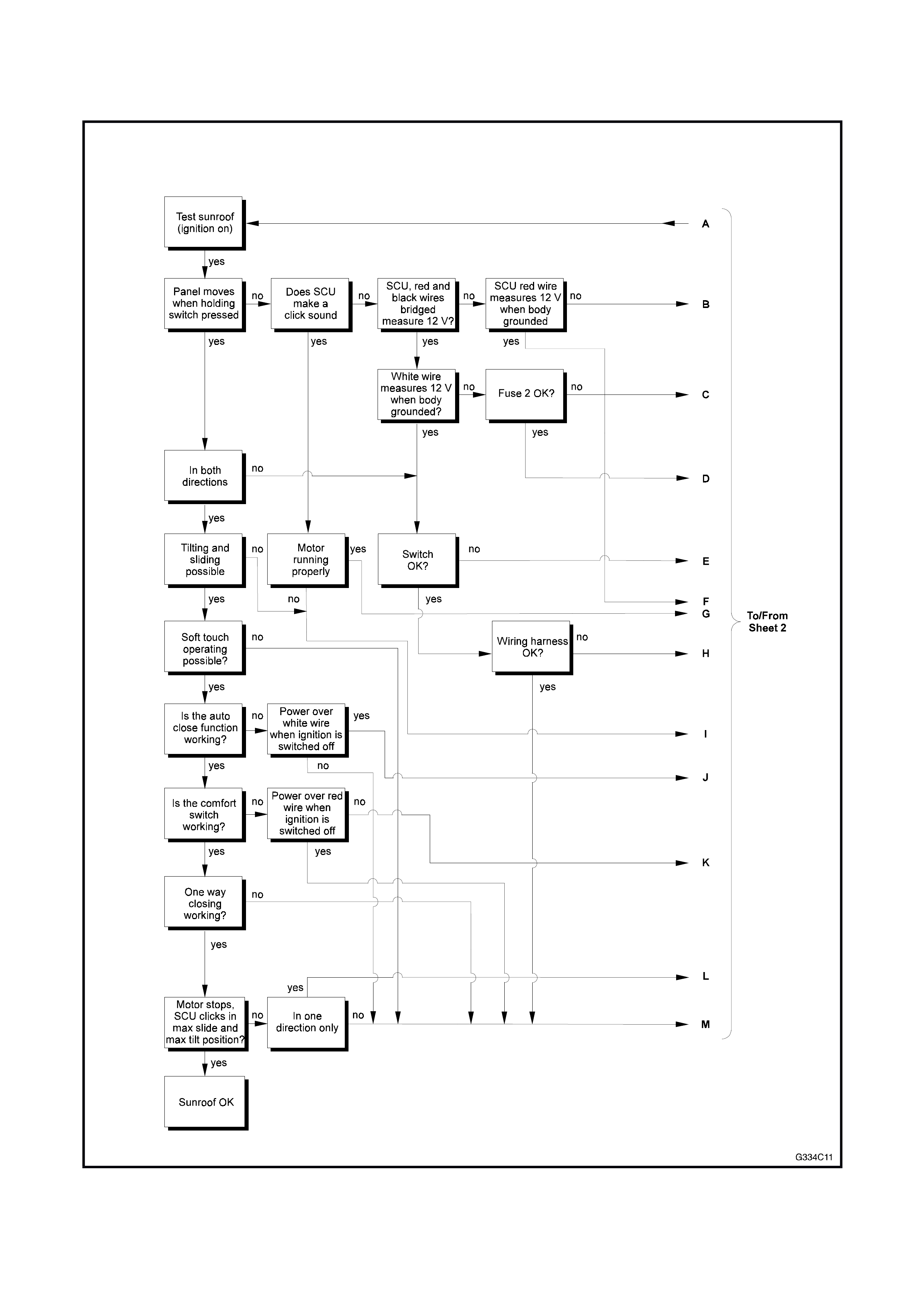
3.3 TROUBLE SHOOTING GUIDE