SECTION 4D - VT SERIES SOUND SYSTEM
CAUTION:
This vehicle will be equipped with a Supplemental Restraint System (SRS). A SRS will consist of
either seat belt pre-tension ers and a driver’s air bag , seat belt pre-t ensioners and a driv er’s and front
passenger’s air bag s or seat belt pre-tensio ners, driver’s and fron t passenger’s air bags and left and
right hand side air bags. Depending upon the system fitted, refer to SAFETY PRECAUTIONS, Section
12M Supplemental Restraint System in the VT Series I Service Information, before performing any
service operation on or around any SRS components, the steering mechanism or wiring. Failure to
follow the SAFETY PRECAUTIONS could result in SRS deployment, resulting in possible personal
injury or unnecessary SRS system repairs.
CAUTION:
This v ehicle may be equipped w ith LPG ( Liquefied Pet roleum Gas). In th e interests of safet y, the LPG
fuel system should be isolated by turning 'OFF' the manual service valve and then draining the LPG
service lines, before any service work is carried out on the vehicle. Refer to the LPG leaflet included
with the Owner's Handbook for details or in the VT Series I Service Information for more specific
servicing information.
1. GENERAL INFORMATION
This Section of the Holden By Design Packages Service Information Supplement describes the two HBD
Sound Systems available for VT Series vehicles.
UPGRADE
The radio cassette CD upgrade is a replacement of the standard radio cassette audio unit. It includes a single
CD player and is similar to the unit fitted as standard to Berlina models, without manual power antenna
control.
No changes are made to the existing 6 speakers or other components.
PREMIUM SOUND SYSTEM
The HBD premium sound system is a top of the line package, individually tailored for sedan and wagon
models.
Sedan
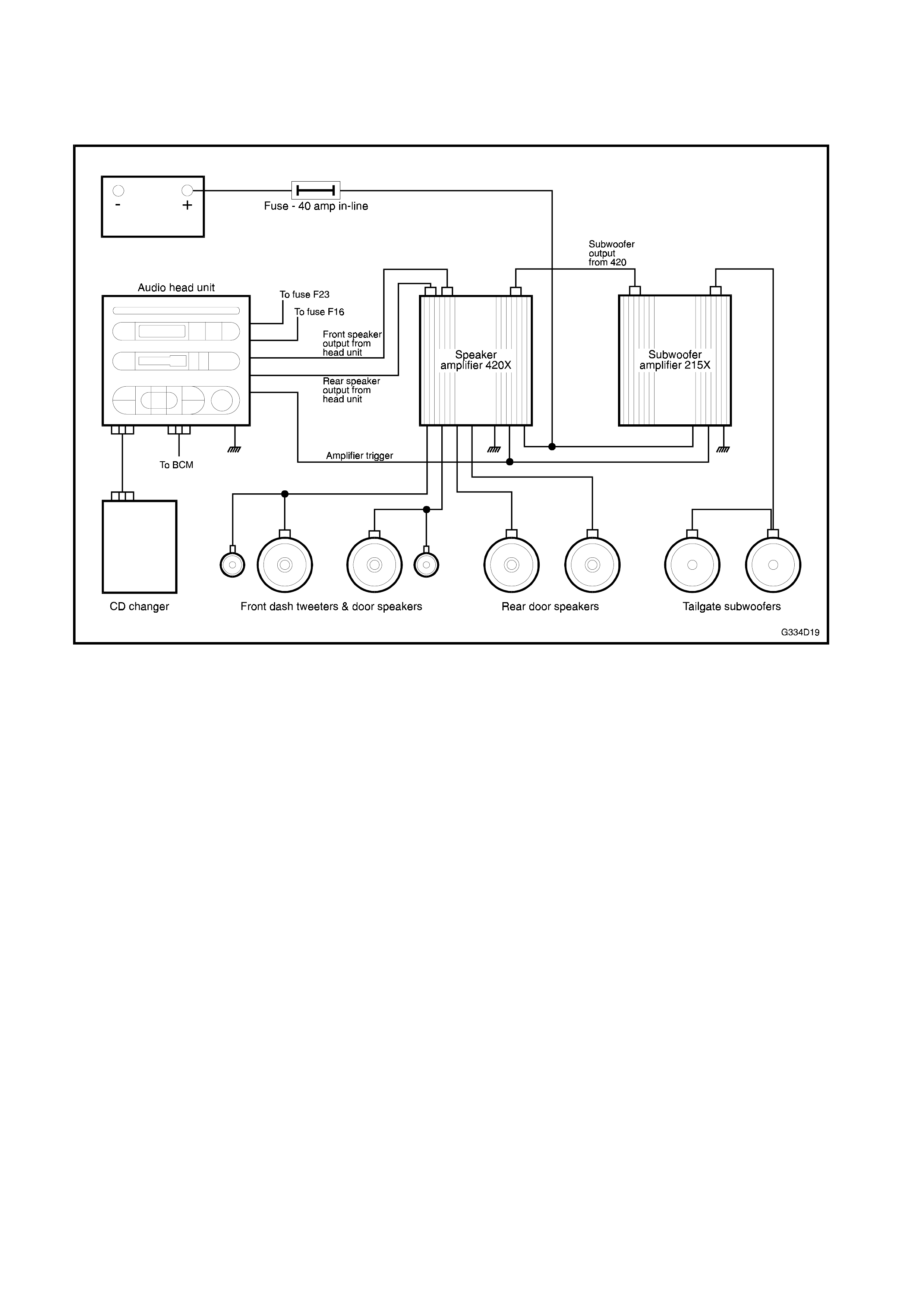
The premium sound system for sedan models consists of:
• 12 speakers - four 2-way 65W RMS door speakers, two dashboard tweeters and two 80W RMS rear
parcel shelf subwoofers,
• 2 amplifiers - one bridged 1 x 260W RMS for the subwoofers and one 4 x 80W RMS for the door
speakers and tweeters.
• 10 stack CD changer, and
• Double DIN Audio head unit (woodgrain finished for Calais models).
Total power output 580 Watts.
Wagon
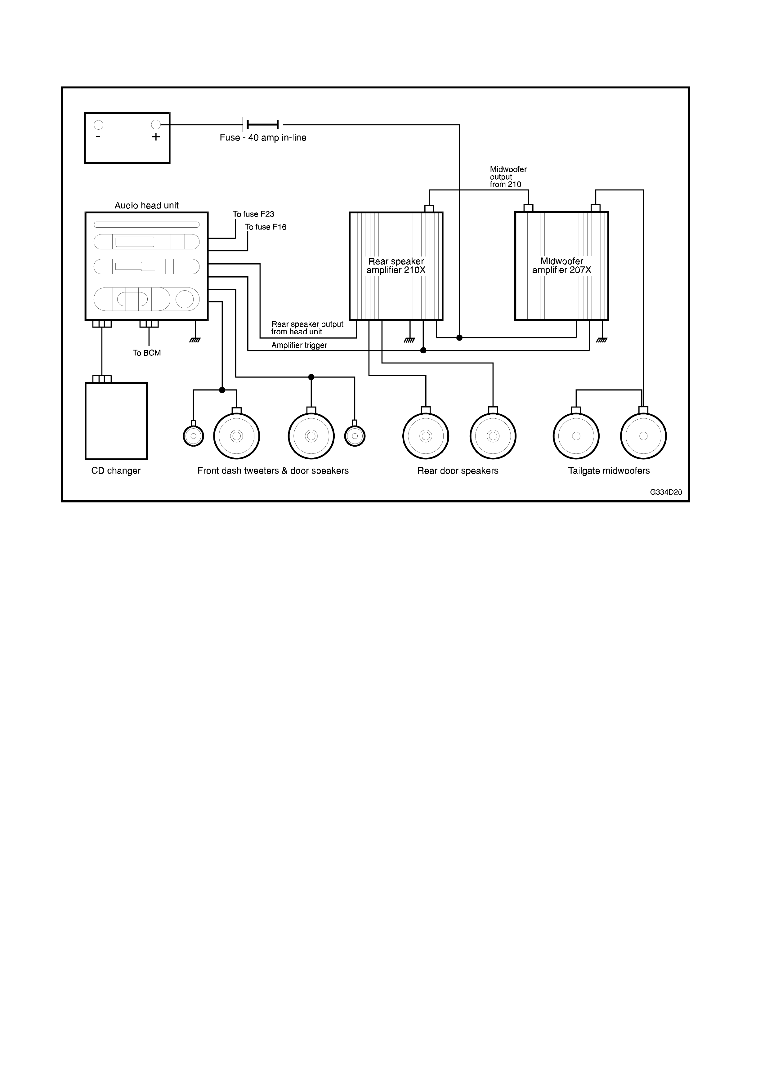
The premium sound system for wagon models consists of:
• 12 speakers - four 2-way 65W RMS door speakers, two dashboard tweeters and two 100W RMS
tailgate midwoofers,
• 2 amplifiers - one bridged 1 x 110W RMS for the midwoofers and one 2 x 80W RMS for the rear door
speakers. The head unit supplies 2 x 45W RMS for the front speakers and tweeters.
• 6 stack CD changer, and
• Double DIN Audio head unit.
Total power output is 360 Watts.
For information not contained in this Section, refer to Section 12D AUDIO SYSTEM of the VT Series I
Service Information.
Figs. 4D-1 & 4D-2 illustrate the premium sound system components and their locations.
NOTE: For information not contained in this Section and assistance or servicing of the Holden By Design
premium sound system, contact Eurovox Pty Ltd (03) 9755 5533.
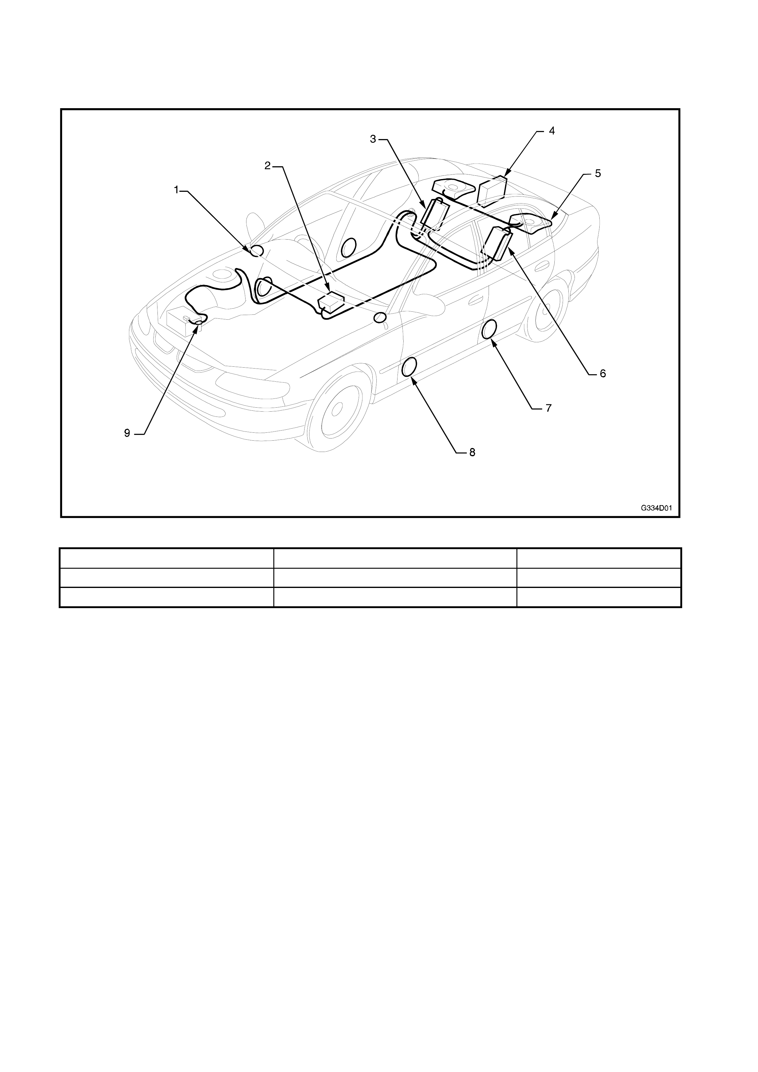
1.1 MAJOR COMPONENTS
SEDAN
Figure 4D-1
1. Dash tweeter 4. CD changer (10 stack) 7. Rear door speaker
2. Audio head unit 5. Subwoofer 8. Front door speaker
3. Speaker amplifier (Model 420X) 6. Subwoofer amplifier (Model 215X) 9. 40 amp in-line fuse
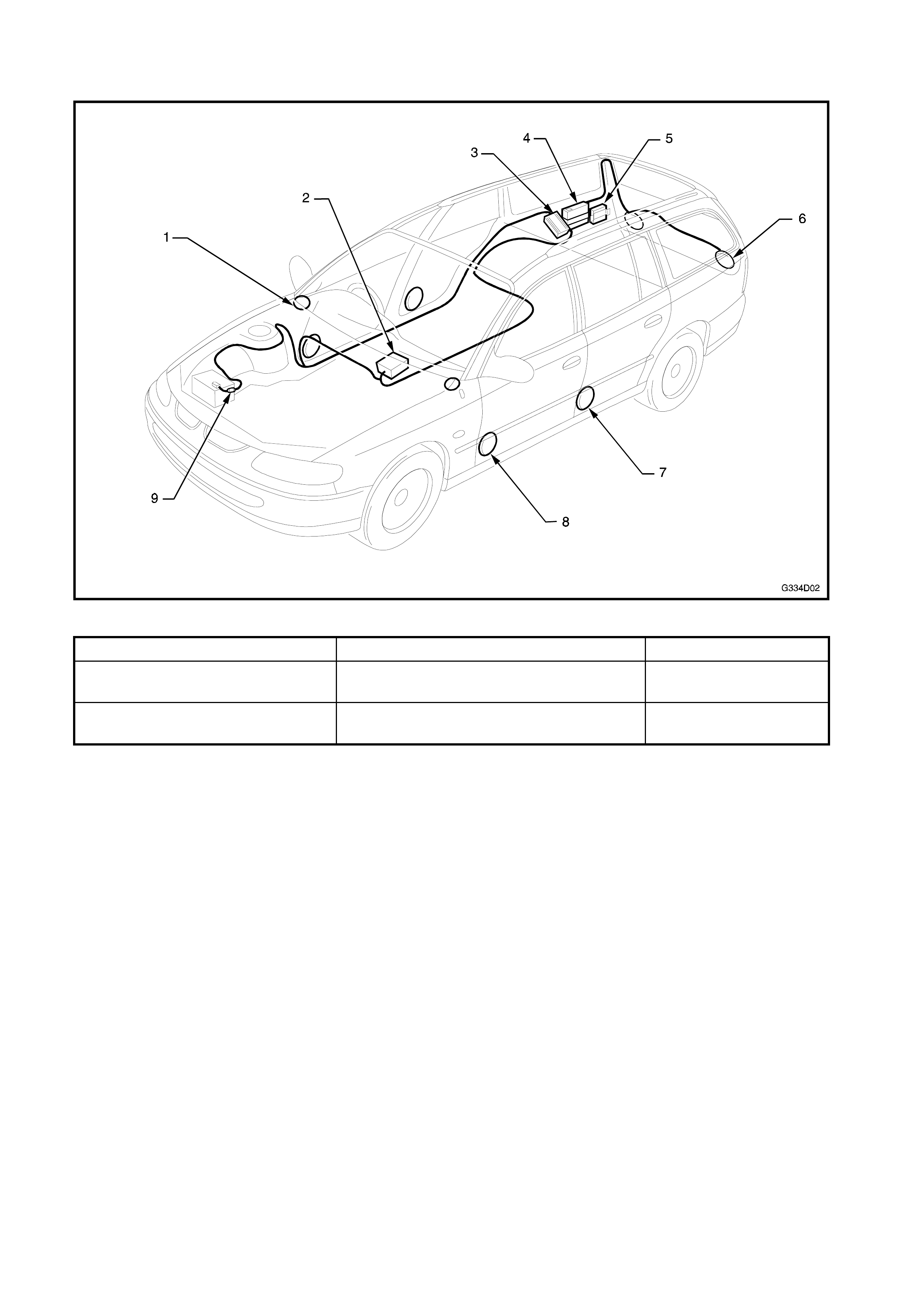
WAGON
Figure 4D-2
1. Dash tweeter 4. CD changer (6 stack) 7. Rear door speaker
2. Audio head unit 5. Rear door speaker amplifier (Model
210X) 8. Front door speaker
3. Midwoofer amplifier (Model
207X) 6. Midwoofer 9. 40 amp in-line fuse


3. PREMI UM SOUND SYSTEM
3.1 AUDIO HEAD UNIT
While the appearance of the premium sound system
audio head unit is similar to the standard VT Series
audio head unit, depending trim level either a
replacement head unit is fitted or internal changes are
made to accommodate the integration of the premium
components.
The service procedures for the Holden By Design
audio head unit are the same as the standard audio
unit fitted to VT Series Vehicles, except for the wiring
connections as shown in Fig. 4D-4, Calais and Fig.
4D-5, Executive & Berlina.
Refer to Section 12D AUDIO SYSTEM of the VT
Series I Service Information for further information. Figure 4D-4
1. CD changer input
2. Amplifier trigger
3. Speaker
4. Speaker
5. Speaker
6. Speaker
7. Main wiring harness
8. RCA
Figure 4D-5
1. Amplifier trigger
2. To rear door
speakers from rear
speaker amplifier
3. Main wiring harness
4. Signal output to rear
door speaker
amplifier
5. CD changer input
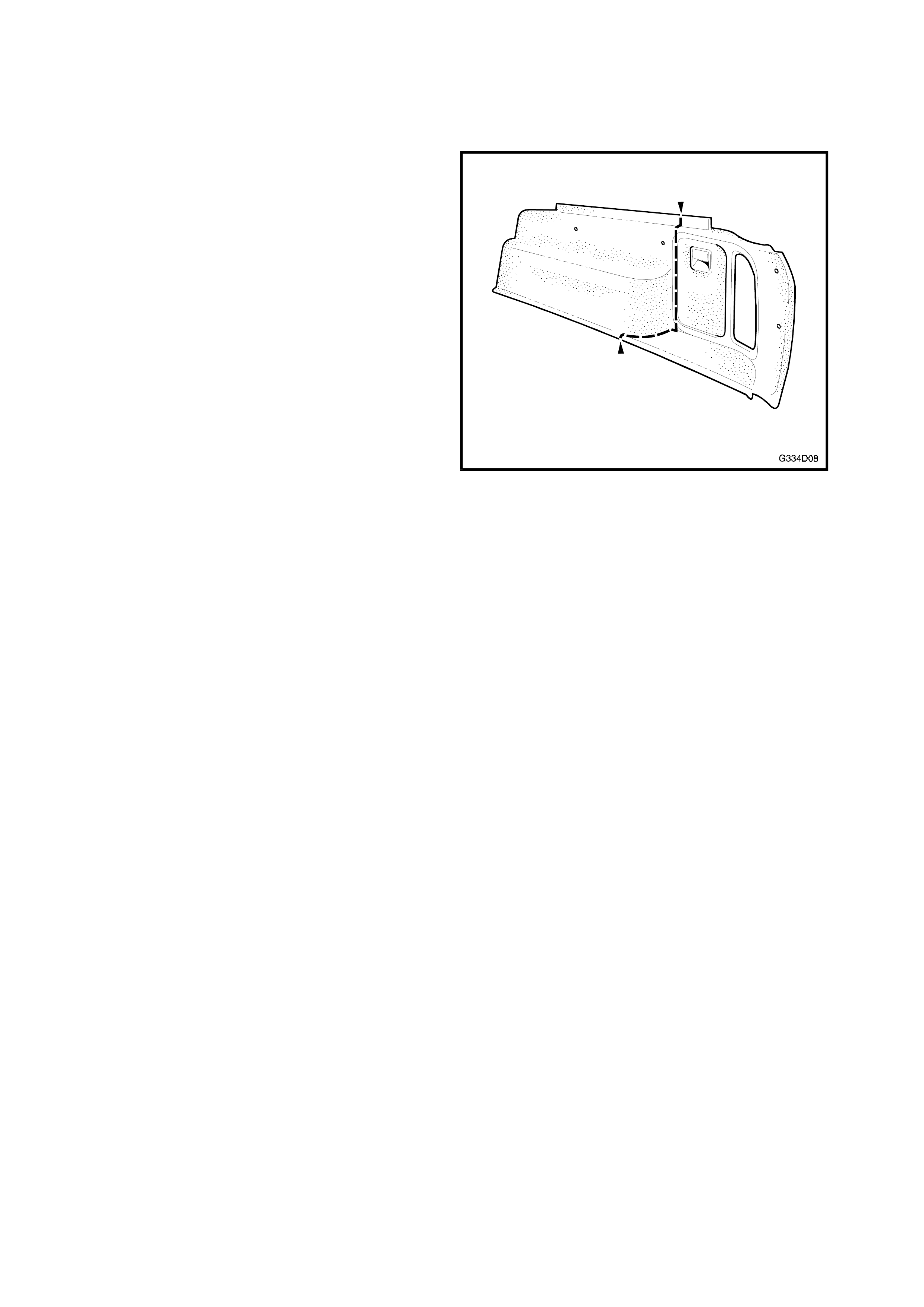
3.2 WAGON SIDE TRIM
The RH side trim for the premium sound system is
modified to accommodate the CD changer and
midwoofer amplifier.
If the side trim is replaced, a standard trim and a
premium sound system section (3) in Fig. 4D-7 will be
required. The standard trim is cut at the location
shown and the front section discarded. The storage
pocket is also removed from behind as it will foul with
the rear door speaker amplifier which is situated
behind the cover.
The two sections are then fitted together on assembly
with the side pocket surround overlapping the join.
Figure 4D-6
REMOVE
1. Lower the RH rear seat backrest.
2. Remove the rear quarter window lower trim (1)
and trim extension (2).
3. Remove the fir tree retainers attaching the side
trim and remove the front (3) and rear (4)
sections.
Figure 4D-7
INSTALL
Installation is the reverse of removal.
TIP: To conceal the join of the two sections, pile from
the discarded original section can be removed with a
knife and glued into the join with superglue.

3.3 CD CHANGER
SEDAN
The sedan CD changer is located in the rear
compartment and is the same unit fitted as standard
with VT Series Calais models.
For service procedures for the Holden By Design CD
changer refer to Section 12D, AUDIO SYSTEM of
the VT Series I Service Information.
WAGON
Remove
1. Remove the RH side trim as described in Section
3.2, Wagon Side Trim.
2. Remove the 4 screws attaching the CD changer
bracket (1) to the side panel.
3. Disconnect the wiring connectors and remove the
CD changer (2).
4. If required, remove the four screws attaching the
mounting bracket to the CD changer.
Figure 4D-8
Install
NOTE: If the inner side panel has been replaced,
construct a drilling template from light card by tracing
or photocopying Fig. 4D-9. Place the template on the
side panel, aligning the large hole with the hole (3) in
Fig. 4D-8. Mark and drill the two small holes, which
are used for the CD changer mounting bracket rear
screw holes.
1. Installation procedures are the reverse of
removal.
2. Install the side trim. Refer to 3.2 WAGON SIDE
TRIM in this Section.
Figure 4D-9
3.4 AMPLIFIERS
Four unique amplifiers are used for the Holden By
Design premium sound system; two for sedan and
two for wagon.
NOTE 1: Wiring f or the am plif iers is not colour c oded.
Prior to the removal of any com ponents, tag the wires
and note their location.
NOTE 2: The amplifiers are specifically adjusted
during installation to ensure optimum performance.
These settings should not be tampered with.
Following assembly of the premium sound system
components, check the settings are as shown in 3.5
AMPLIFIER SETTINGS in this Section. If you are in
any doubt as to the settings or the perf orm ance of the
premium sound system, contact Eurovox Pty, Ltd on
(03) 9755 5533.
SEDAN SUBWOOFER A MPLIFIER (MODEL 215X)
Remove
1. From within the rear compartment, remove the
four screws (1) attaching the amplifier mounting
plate (2) to the rear seat back panel.
2. Disconnect the wiring connectors and earth lead
and remove the amplifier assembly.
3. If required, remove the four screws (3) attaching
the amplifier (4) to the mounting plate.
Figure 4D-10
Install
Installation is the reverse of removal.
NOTE: Ensure the amplifier settings are correct, refer
to 3.5 AMPLIFIER SETTINGS in this Section.
SEDAN SPEAKER AMPLIFIER (MODEL 420X)
Remove
1. From within the rear compartment, remove the
four screws (1) attaching the amplifier mounting
plate (2) to the rear seat back panel.
2. Disconnect the wiring connectors and earth point
and remove the amplifier assembly.
3. If required, remove the four screws (3) attaching
the amplifier (4) to the mounting plate.
Figure 4D-11
Install
Installation is the reverse of removal.
NOTE: Ensure the amplifier settings are correct, refer
to Section 3.5 A MPLIFIER SETTINGS in this Section.
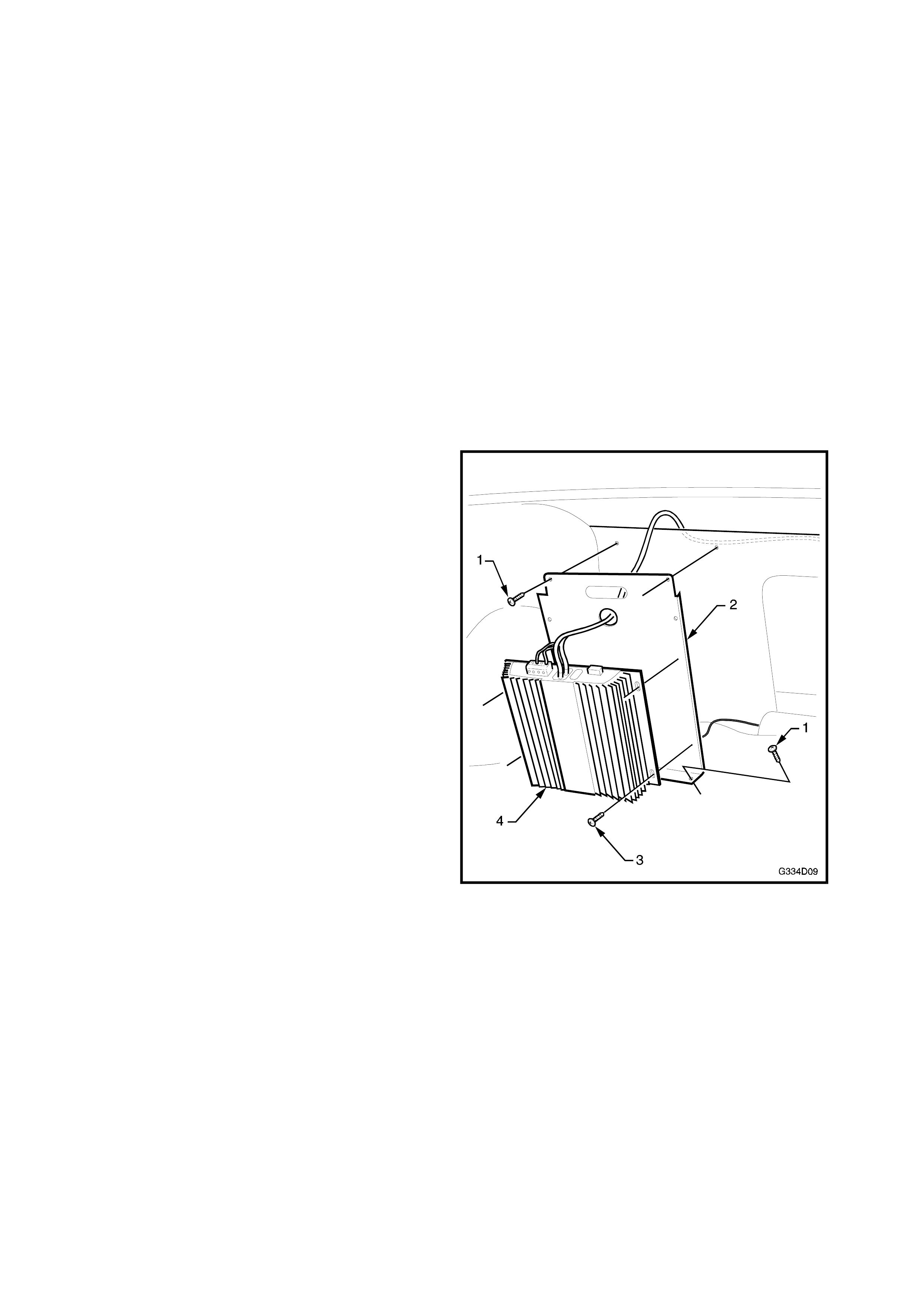
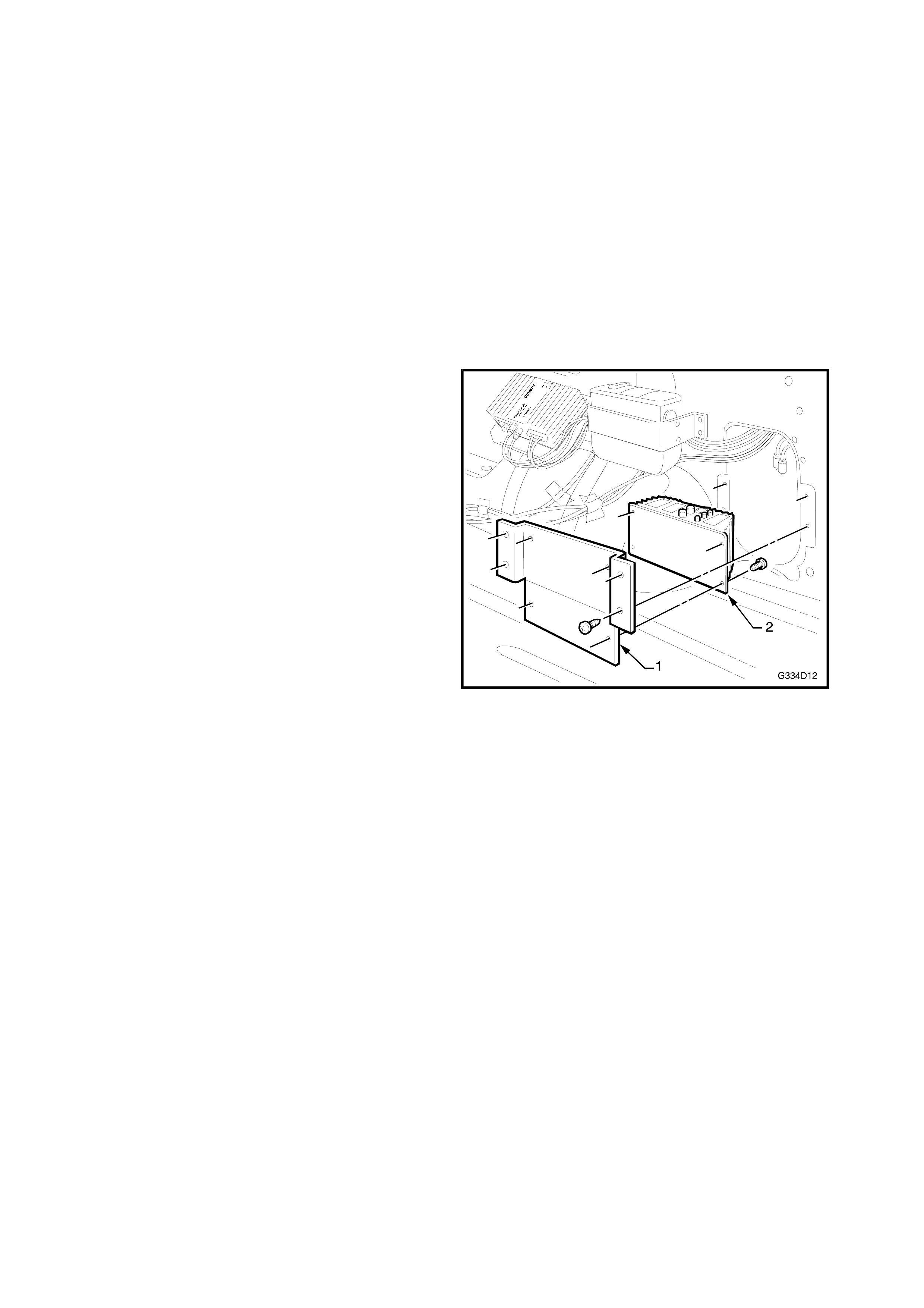
WAGON MIDWOOFER AMPLIFIER (MODEL 207X)
Remove
1. Remove the rear compartment side trim as
described in 3.2 WAGON SIDE TRIM in this
Section.
2. Remove the four screws attaching the amplifier
(1) to the amplifier mounting plate (2).
3. Disconnect the wiring connectors and remove the
amplifier.
4. If required, remove the four screws attaching the
amplifier mounting plate to the side panel and
wheel house.
Figure 4D-12
Install
1. Installation procedures are the reverse of
removal.
2. Install the side trim, refer to 3.2 WAGON SIDE
TRIM in this Section.
NOTE: Ensure the amplifier settings are correct prior
to fitting the side trim, refer to 3.5 AMPLIFIER
SETTINGS in this Section.
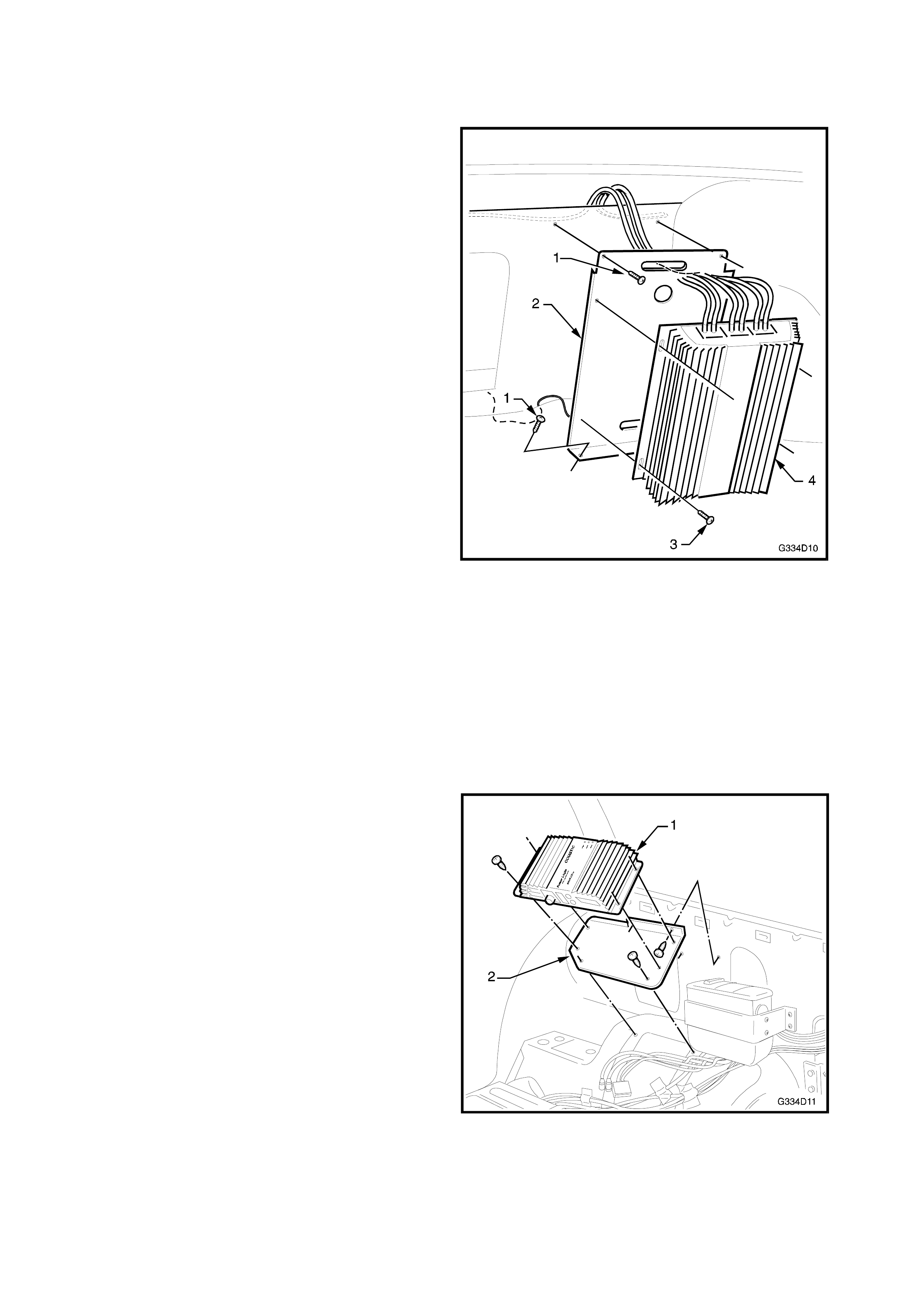
WAGON REAR DOOR SPEAKER AMPLIFIER
(MODEL 210X)
Remove
1. Remove the rear compartment side trim as
described in 3.2 WAGON SIDE TRIM in this
Section.
2. Remove the four screws attaching the amplifier
mounting plate (1) to the side panel and remove
the amplifier assembly.
3. Disconnect the wiring connectors and remove the
amplifier assembly.
4. If required, remove the four screws attaching the
amplifier (2) to the mounting plate.
Figure 4D-13
Install
1. Installation procedures are the reverse of
removal.
2. Install the side trim. Refer to 3.2 WAGON SIDE
TRIM in this Section.
NOTE: Ensure the amplifier settings are correct prior
to fitting the side trim, refer to 3.5 AMPLIFIER
SETTINGS in this Section.
3.5 AMPLIFIER SETTINGS
The amplifiers are specifically adjusted during
installation to ensure optimum performance. These
settings should not be tampered with. Following
assembly of the premium sound system components,
check the settings are as shown in the following
diagrams.
If you are in any doubt as to the settings or the
performance of the premium sound system, contact
Eurovox Pty, Ltd on (03) 9755 5533.
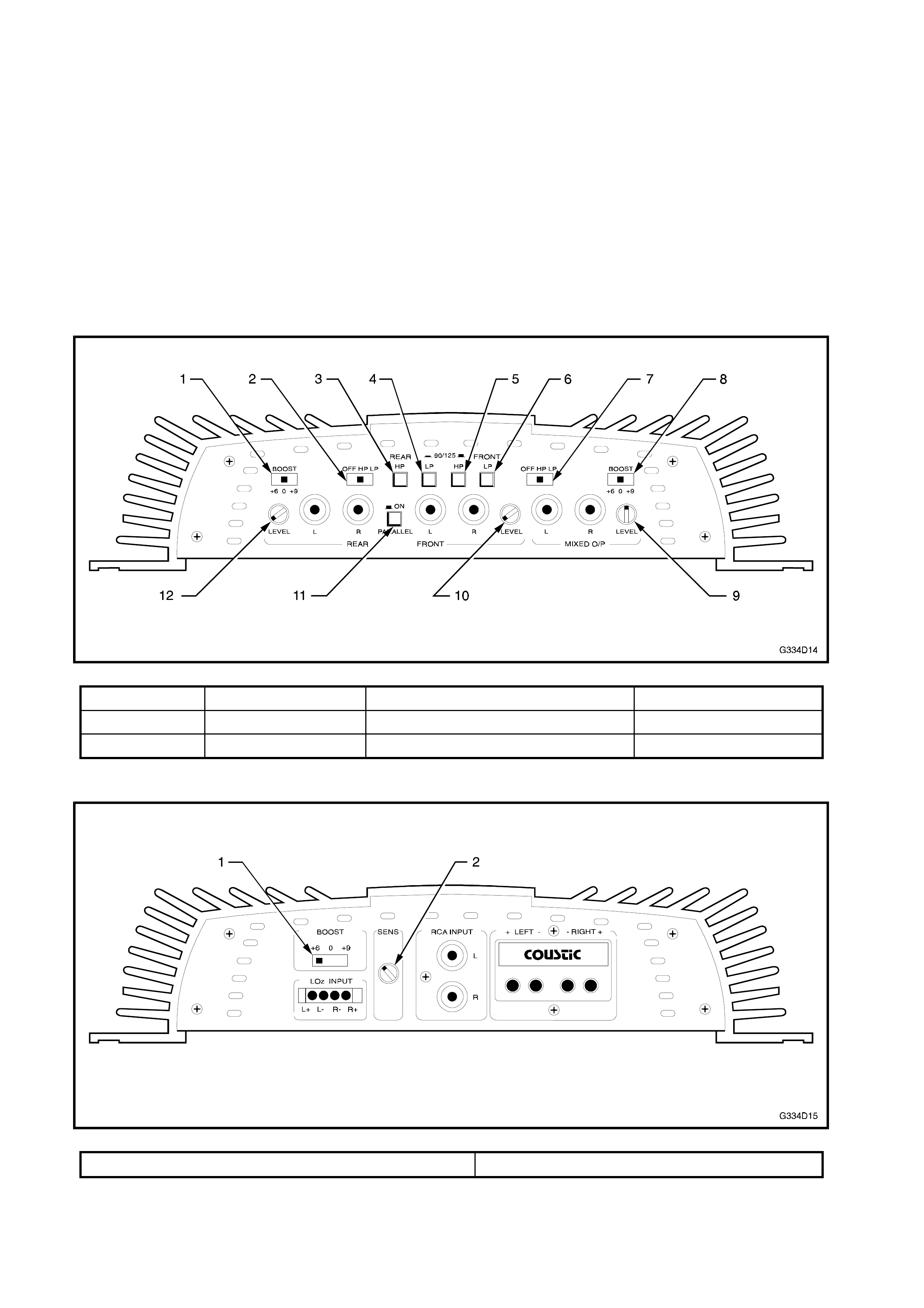
SEDAN SPEAKER AMPLIFIER - MODEL 420X
Figure 4D-14
1. 0 4. Out 7. HP 10. Full anti-clockwise
2. HP 5. Out 8. 0 11. Out
3. Out 6. Out 9. Full clockwise, back to 12 o’clock 12. Full anti-clockwise
SEDAN SUBWOOFER AMPLIFIER - MODEL 215X
Figure 4D-15
1. +6 2. Full anti-clockwise, forward to 11 o’clock
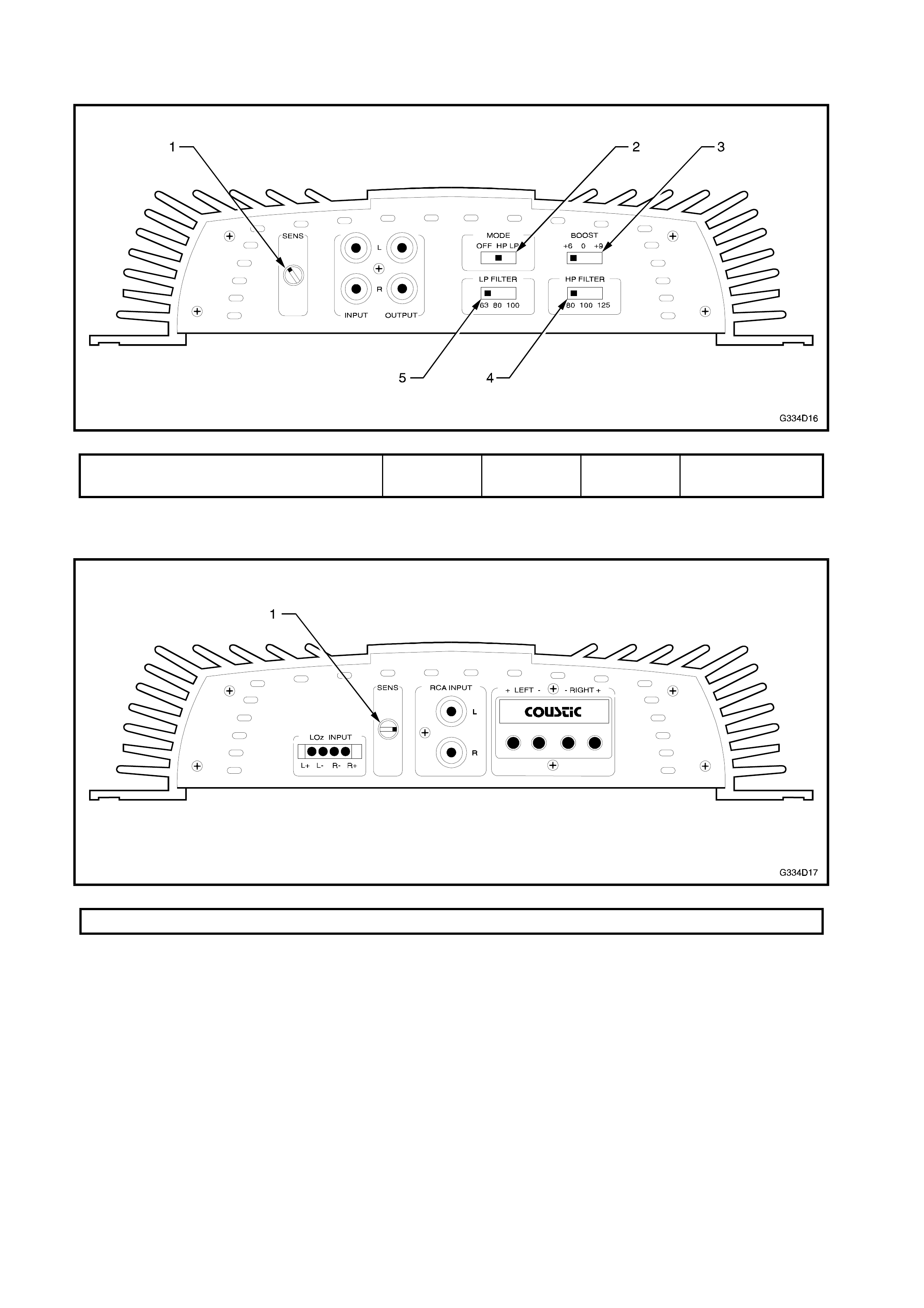
WAGON REAR DOOR SPEAKER AMPLIFIER - MODEL 210X
Figure 4D-16
1. Full anti-clockwise, forward to 11
o’clock 2. HP 3. +6 4. 80 5. Not used
WAGON MIDWOOFER AMPLIFIER - MODEL 207X
Figure 4D-17
1. Full clockwise, back to 3 o’clock

3.6 SPEAKERS
DASH TWEETERS
The dash tweeters are not changed from those fitted as standard to VT Series vehicles. For service
procedures, refer to Section 12D AUDIO SYSTEM of the VT Series I Service Information.
DOOR SPEAKERS
The four door speakers are upgraded as part of the Holden By Design premium sound system, however
service procedures remain unchanged. Refer to Section 12D AUDIO SYSTEM of the VT Series I Service
Information for further information.
SEDAN SUBWOOFER
The sedan subwoofers are added or for Calais models, upgraded as part of the Holden By Design
premium sound system. Service procedures remain unchanged from those described in Section 12D
AUDIO SYSTEM of the VT Series I Service Information.
WAGON MIDWOOFER
The wagon midwoofers are unique to the Holden By
Design premium sound system. No other VT Series
vehicle has speakers mounted in the tailgate.
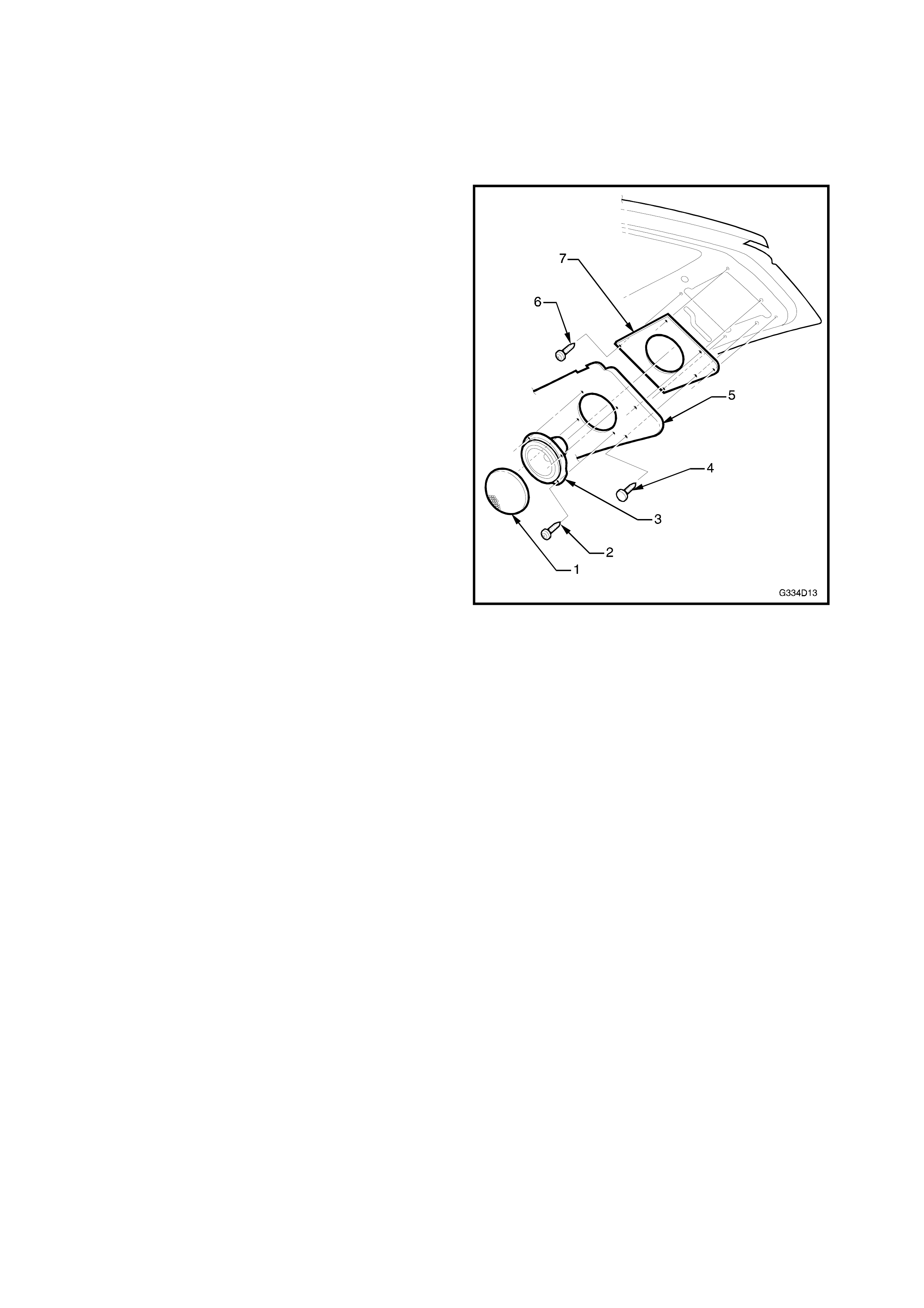
Remove
1. Carefully prise off the midwoofer cover (1) using a
fine bladed screwdriver.
2. Remove the four screws (2) attaching the
midwoofer (3).
3. Disconnect the wiring connectors and remove the
midwoofer.
4. Remove the upper tailgate trims by gently prising
away from the tailgate panel. Refer to Section 1A-
4, REAR COMPARTMENT LID & TAILGATE of
the VT Series I Service Information for further
information.
5. Remove the fir tree trim clips (4) attaching the
tailgate lower trim (5) to the tailgate panel.
6. Remove the four screws (6) attaching the
midwoofer mounting plate (7) to the tailgate panel.
Figure 4D-18
Install
Installation is the reverse of removal noting the
following.
1. If the lower tailgate trim has been replaced, place
the midwoofer mounting plate on the back of the
trim and align the two fir tree trim clip holes.
Mark the trim around the midwoofer opening and using
a sharp knife, cut out the hole.
2. If the tailgate has been replaced, align the
midwoofer mounting plate with the two fir tree trim
clip holes.
Mark and drill the four mounting plate screw holes.