
SECTION 4F - VT SERIES COUNTRY DRIVING &
LOAD MANAGEMENT
CAUTION:
This vehicle will be equipped with a Supplemental Restraint System (SRS). A SRS will consist of
either seat belt pre-tension ers and a driver’s air bag , seat belt pre-t ensioners and a driv er’s and front
passenger’s air bag s or seat belt pre-tensio ners, driver’s and fron t passenger’s air bags and left and
right hand side air bags. Depending upon the system fitted, refer to SAFETY PRECAUTIONS, Section
12M Supplemental Restraint System in the VT Series I Service Information, before performing any
service operation on or around any SRS components, the steering mechanism or wiring. Failure to
follow the SAFETY PRECAUTIONS could result in SRS deployment, resulting in possible personal
injury or unnecessary SRS system repairs.
CAUTION:
This v ehicle may be equipped w ith LPG ( Liquefied Pet roleum Gas). In th e interests of safet y, the LPG
fuel system should be isolated by turning 'OFF' the manual service valve and then draining the LPG
service lines, before any service work is carried out on the vehicle. Refer to the LPG leaflet included
with the Owner's Handbook for details or in the VT Series I Service Information for more specific
servicing information.
1. GENERAL INFORMATION
This Section of the Holden By Design Service Information Supplement describes the removal and replacement
of the Country Driving and Load Management packages which consist of:
• Country Roo Bar,
• Wagon Cargo Barrier,
• Wagon 3rd Seat, and
• Level ride suspension
The country roo bar has been designed by Holden to fully integrate with the many safety system s built into every
VT Series Vehicle. The package includes a revised front bumper support beam to accommodate mounting of
the country roo bar.
The wagon cargo bar rier is m ade from tubular s teel and wire mesh and is designed to res train ca rgo in the rear
compartment of the vehicle or separate pets from passengers.
The wagon 3rd seat is designed to accom m odate two children up to 38 k g. Seat belts for the 3rd s eat occupants
are integrated into the seat assembly. The wagon 3rd seat is easily removed from its mountings if desired.
Level ride suspens ion maintains the co rrect ride height when towing or the vehicle is heavily laden. The Holden
By Design system features electronic control of an air compressor and rear air shock absorber system.
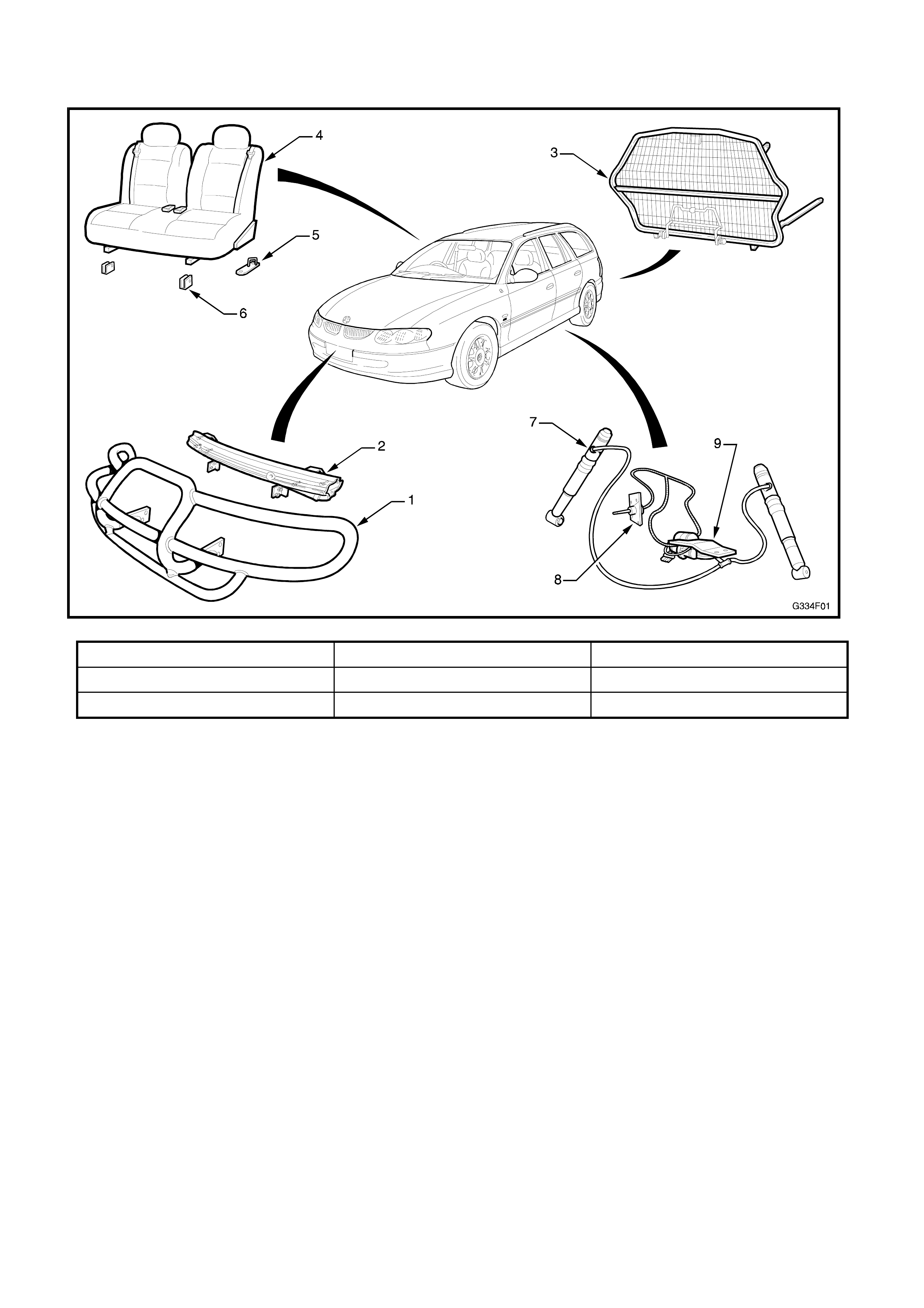
1.1 MAJOR COMPONENTS
Figure 4F-1
1. Country roo bar 4. Wagon 3rd seat 7. Superlift shock absorber
2. Bumper reinforcement 5. 3rd seat rear striker 8. Ride height sensor
3. Cargo barrier 6. 3rd seat front pivot mount 9. Compressor assembly
2. COUNTRY ROO BAR
REMOVE
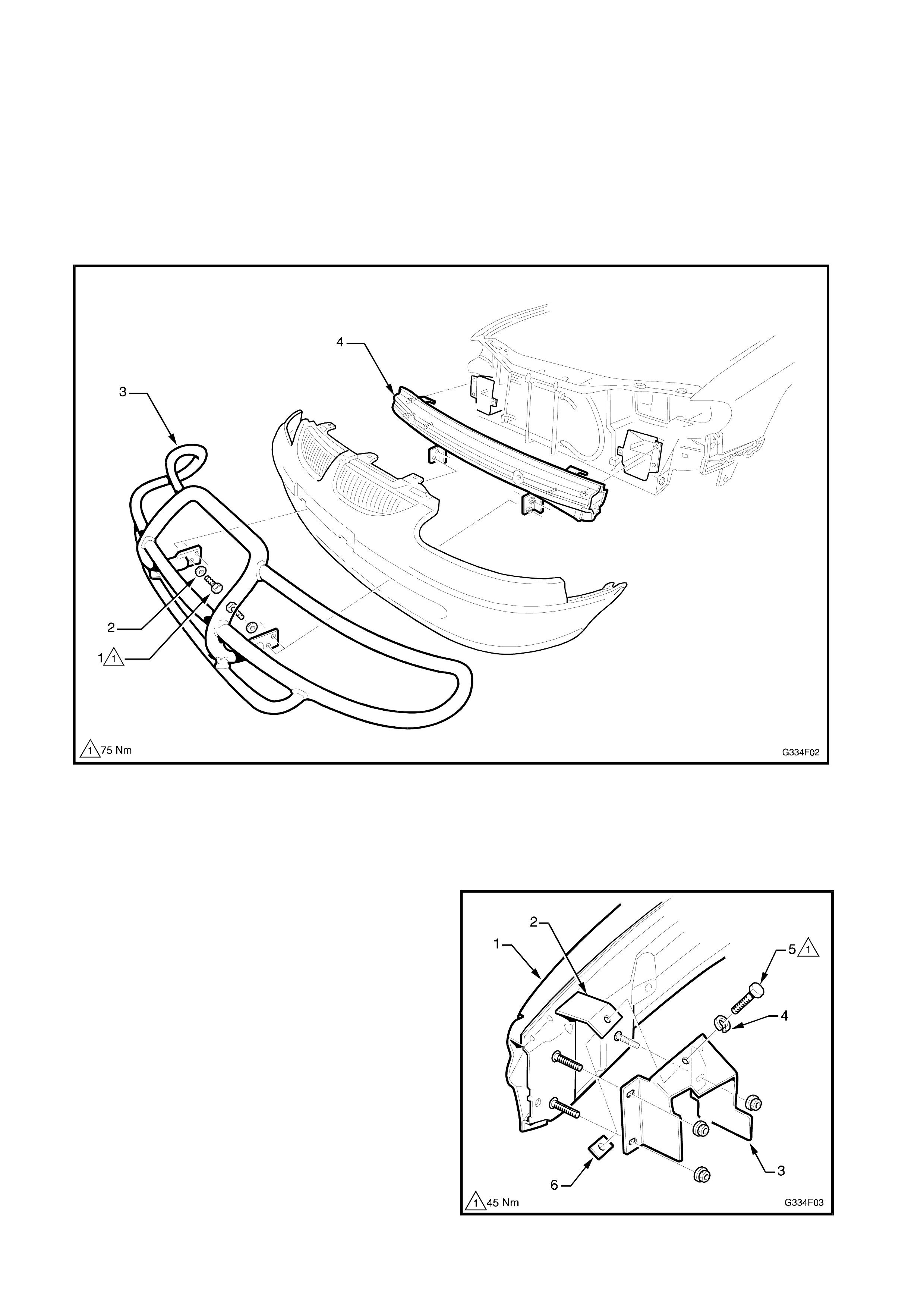
1. From within the bumper facia lower opening,
remove the four bolts (1) and washers (2)
attaching the country roo bar (3) to the bumper
support beam (4).
NOTE: Have an assis tant support the country roo bar
while performing this operation.
Figure 4F-2
2. Remove the country roo bar.
3. If the bumper facia and/or the support beam are
damaged, follow the removal and replacement
procedures in Section 1D, BUMPER BARS in
the VT Series I Service Information.
NOTE: Where the country roo bar is fitted, the front
bumper support beam (1) differs to the standard unit.
A bracket (2) is added each side, which attaches to
the upper surface of the bumper beam mounting
bracket (3) with a washer (4), M10 bolt (5) and nut
plate (6). The headlights will require removal to
enable access to the bolt (5).
Figure 4F-3
4. If the country roo bar is to be replaced, remove
the number plate by drilling out the four 4.5 mm
rivets.
INSTALL
1. If not already done so, install the front bumper
support beam and facia. Refer Section 1D,
BUMPER BARS in the VT Series I Service
Information.
NOTE: Ensure the c orrect bum per support beam has
been used which accom modates the country roo bar.
Refer Figs. 4F-2 & 4F-3.
2. Have an assistant hold the country roo bar in the
installed position and fit the four M12 bolts and
washers attaching the country roo bar to the
bumper beam.
Refer Fig. 4F-2.
3. Tighten the mounting bolts to the specified
torque.
NOTE: Check for alignment of the country roo bar
prior to fully tightening the mounting bolts.
COUNTRY ROO BAR
ATTACHING BOLT 75 Nm
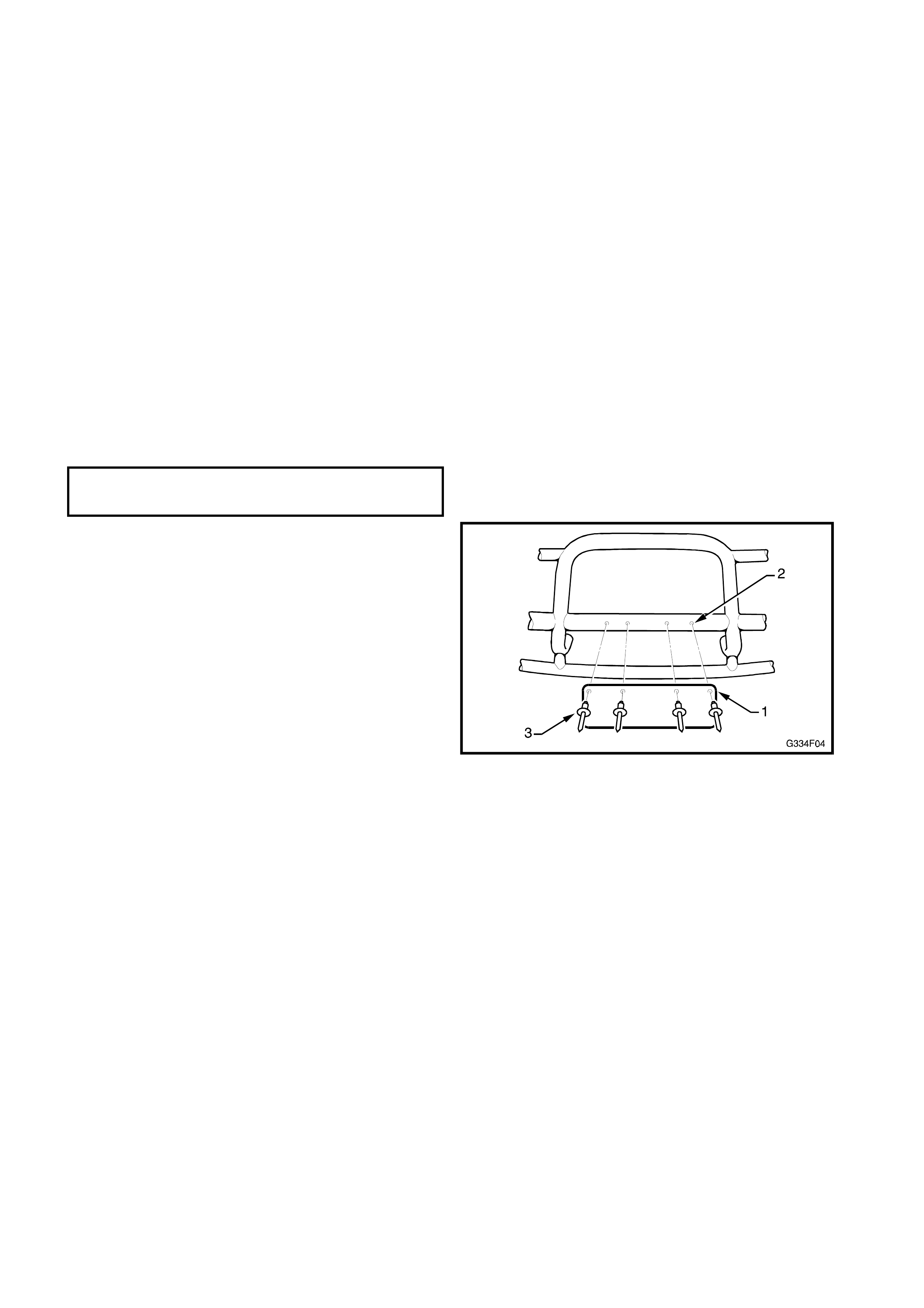
4. If the number plate (1) was removed, align the
outermost number plate mounting holes with the
dimples (2) in the country roo bar and mark.
5. Drill two 4.5 m m holes at the m ark ed dim ples and
attach the number plate with 4.5 mm rivets (3).
6. Using the existing holes in the number plate as a
template, drill a further two 4.5 mm holes and fix
with two 4.5 mm rivets.
Figure 4F-4
3. WAGON CARGO BARRIER
REMOVE
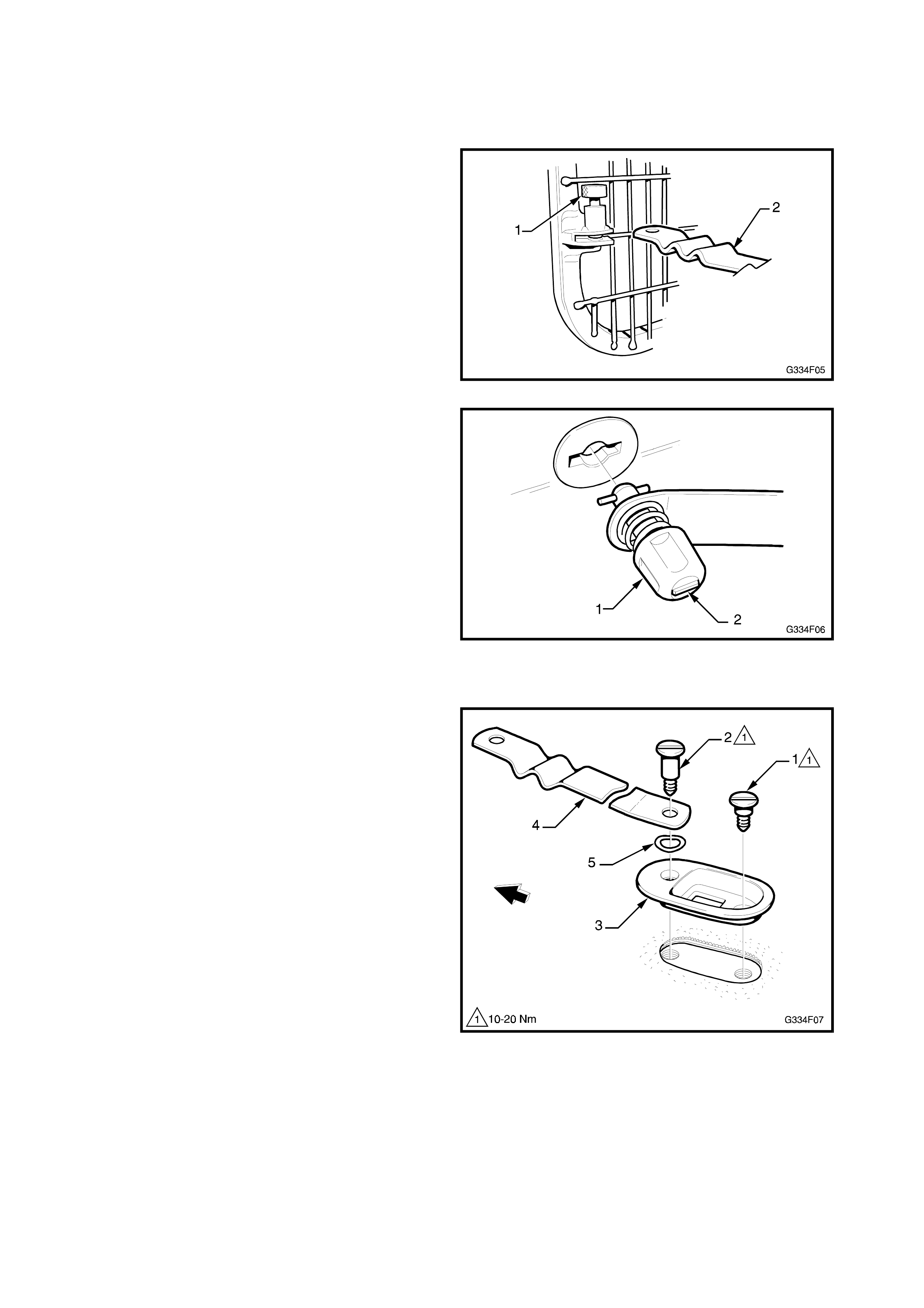
1. If the wagon cargo barrier is located in the front
position, lift the lower quick release pins (1) and
disengage the long straps (2) from each side.
Figure 4F-5
2. Disengage each top quick release lock (1) by
depressing and rotating the knob until the line on
the face of the knob (2) is horizontal.
Figure 4F-6
3. Tilt the top of the wagon cargo barrier rearwards
and remove.
4. If required, unscrew the short (1) and long (2)
shoulder bolts from each floor cover plate (3).
Remove the plate, long strap (4) and wave
washer (5).
Figure 4F-7
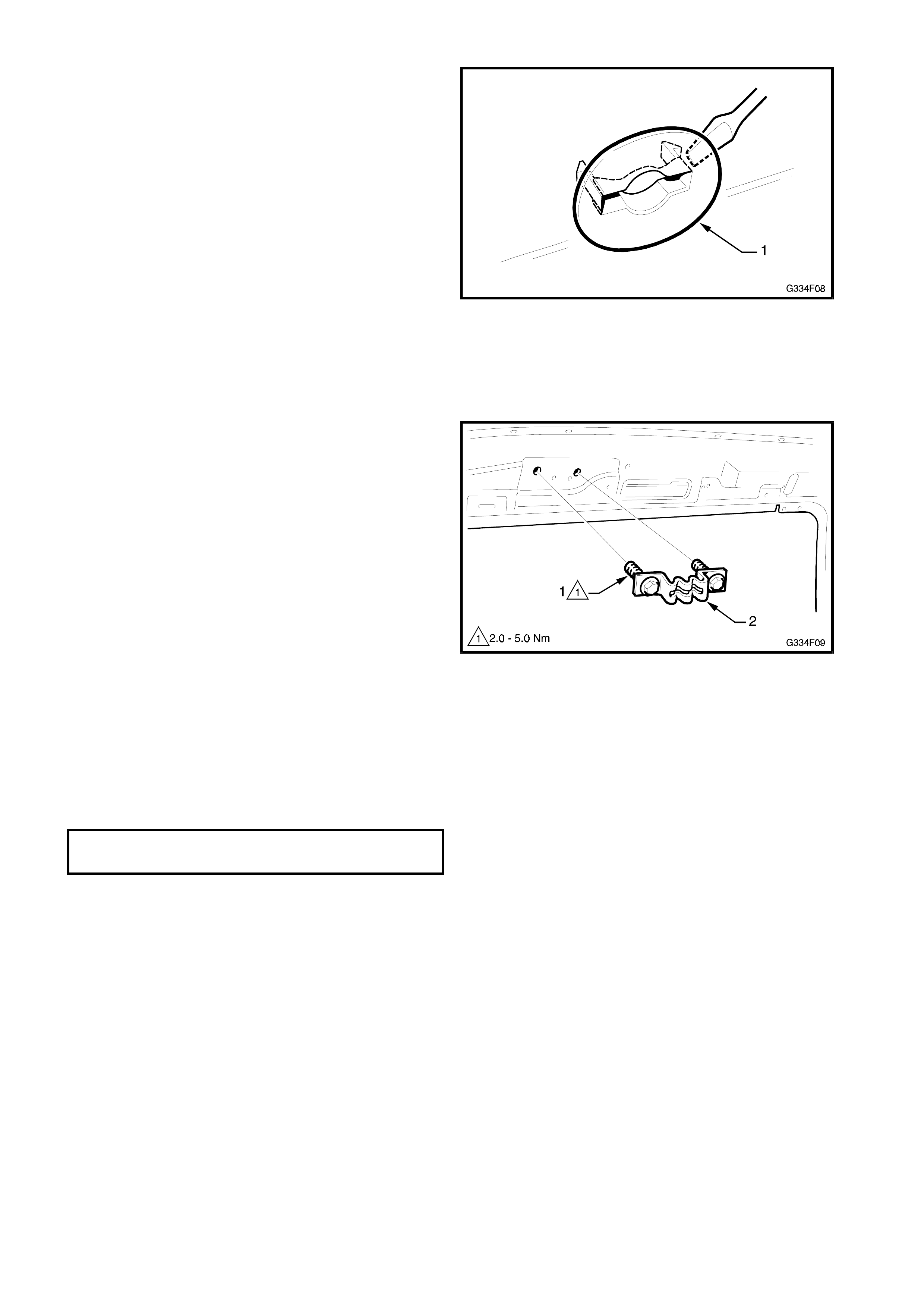
5. If required, use a screwdriver and carefully insert
it behind one end of the top mounting trim plug
(1). W hile pushing towards the centre of the plug
to disengage the tang, lever the plug away from
the headlining.
Figure 4F-8
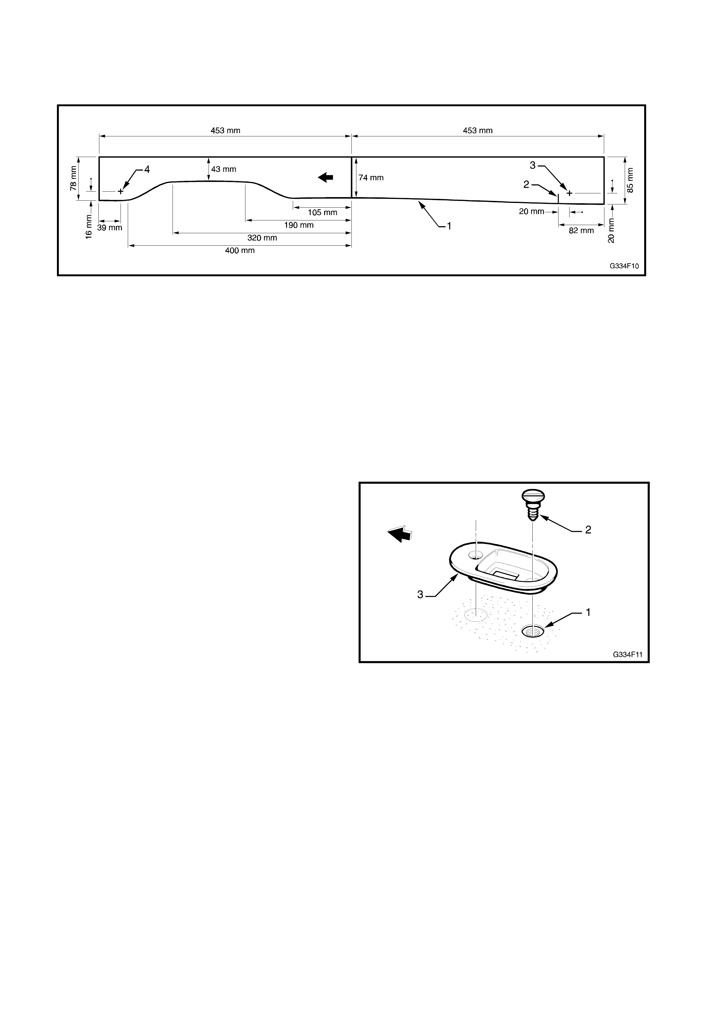
6. If the upper bracket and bolt as sem bly is required
to be removed, remove the upper side trims and
headlining. Refer to Section 1A-8, HEADLINING
& REAR END TRIM in the VT Series I Service
Information.
7. Remove the two bolts (1) attaching each upper
bracket & bolt assembly (2) to the side panel -
inner.
NOTE: The bolts are captive to the bracket.
Figure 4F-9
INSTALL
NOTE: If the upper brack et and bolt assemblies have
not been replaced, proceed to Step 6.
1. Install the top quick release bracket & bolt
assemblies as shown in Fig. 4F-9, prior to
installing the headlining and rear compartment
side trims.
UPPER BRACKET & BOLT
ASSEMBLY 2-5 Nm
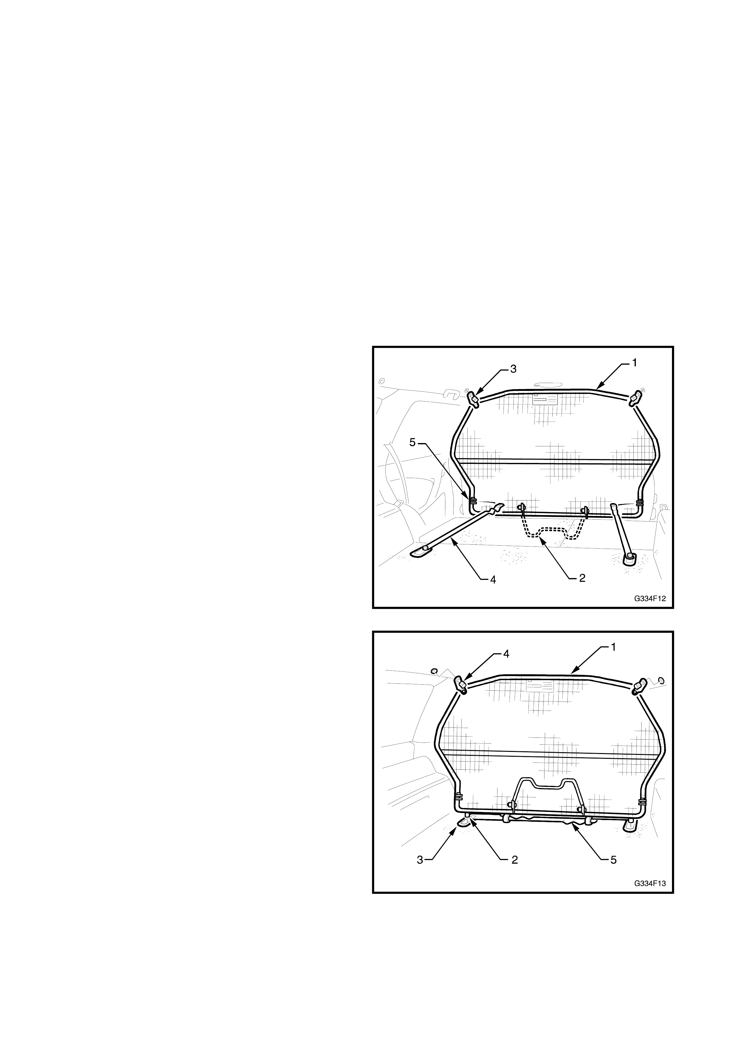
2. If the headlining has been replaced, construct a
template from light card to the dimensions shown
in Fig. 4F-10, for the top mounting trim plugs.
Figure 4F-10
3. Place the bottom edge of the template (1) on the
top edge of the plastic upper side trim. Align the
mar k (2) with the join of the centr e upper s ide trim
to the rear upper side trim. Mark the top mount
location points (3) and (4) on the headlining.
NOTE: T hese mus t be in alignment with the centre of
the top quick release bracket assemblies.
4. Punch a small hole in the headlining. Enlarge the
hole to approximately 25 mm with a knife.
5. Insert the roof trim plug as shown in Fig. 4F-8.
6. If the rear floor trim has not been replaced,
proceed to Step 17.
7. Use the existing floor trim plug hole (1) as the
short shoulder bolt (2) location.
8. Plac e the floor cover plate (3 ) parallel to the body
line.
Figure 4F-11
9. Using the floor cover plate as a guide, mark the
location of the long shoulder bolt hole.
10. Remove the floor trim from the vehicle and cut
out the carpet at the bolt locations using a 30mm
diameter vinyl cutter with a 6 mm drill bit.
11. Turn the floor trim over and remove the sound
proofing from the same locations.
12. Using a sharp knife, remove the carpet and sound
deadening from between the two holes.
13. Using a 30 mm diameter hole saw, cut through
the wood floor panel at the bolt locations.
14. Using a jigsaw, remove the wood from between
the holes. Check for fit of the floor cover plate.
15. Reinstall the floor trim.
16. Fit each floor cover plate noting the assembly
configuration in Fig. 4F-7.
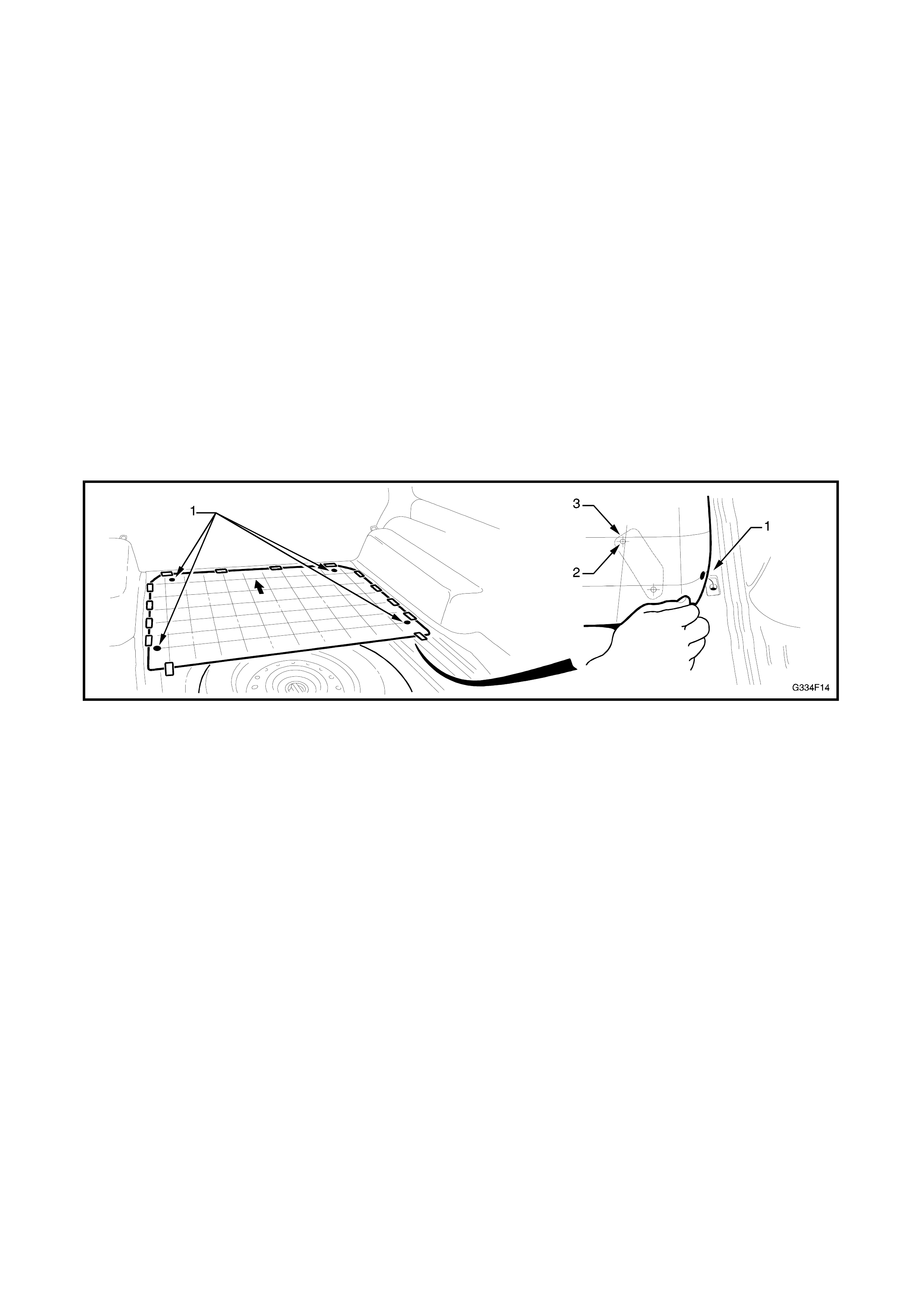
17. Install the wagon cargo barrier in either the front
or rear locations:
Front: Tilt the wagon cargo barrier (1) rearwards
and fold down the leg frame (2) which locates on
the transmission tunnel as shown. Align the top
quick release locks (3) with the corresponding
roof trim plugs. Insert and rotate the top quick
release lock s until the line on the knob is vertical.
Refer Fig. 4F-6. Lock the bottom long straps (4)
into the lower quick release locks (5) and ensure
the locking pins are fully engaged. Refer Fig. 4F-
5.
Figure 4F-12
Rear: Tilt the wagon cargo barrier (1) rearwards
and insert the locating hooks (2) into the slots in
the floor cover plates (3).
Align the top quick release locks (4) with the
corresponding roof trim plugs. Insert and rotate
the top quick release locks until the line on the
knob is vertical. Refer Fig. 4F-6.
The long straps (5) are folded inward and
retained together with the PVC tubing.
Figure 4F-13
4. WAGON 3RD SEAT
4.1 TEMPLATE CONSTRUCTION
A template is only required to be constructed where
the rear floor pan, rear longitudinals, or the rear floor
trim are to be replaced, and no template is available (it
is only supplied with a replacement wagon 3rd seat).
The easiest method for constructing a template is to
trace the original positions off the floor and rear floor
trim onto a sheet, once the components have been
removed.
NOTE: Where the original positions are not
serviceable (the rear floor and/or floor trim is
damaged) follow the procedures provided in
Operations 4.6 & 4.7 in this Section.
WAGON 3RD SEAT MOUNTINGS
1. Tape a sheet of plastic to the floor as shown in
Fig. 4F-14.
Figure 4F-14
2. Mark the four alignment holes as shown (1) and
the forward orientation of the template.
3. Carefully mark each of the eight mounting bolt
holes (2) and the areas where sound deadener
has been removed (3).
WAGON 3RD SEAT REAR FLOOR TRIM PROTRUSIONS
1. Using the previously constructed template, turn it
over and lay it on the underside of the rear floor
trim.
2. Mark the edge of the trim, the areas where the
underfelt and wood / plastic has been removed
and the protrusion slots in the carpet.
3. Store the template in a safe place.
4.2 WAGON 3RD SEAT
REMOVE
1. Fold the wagon 3rd seat backrests forward.
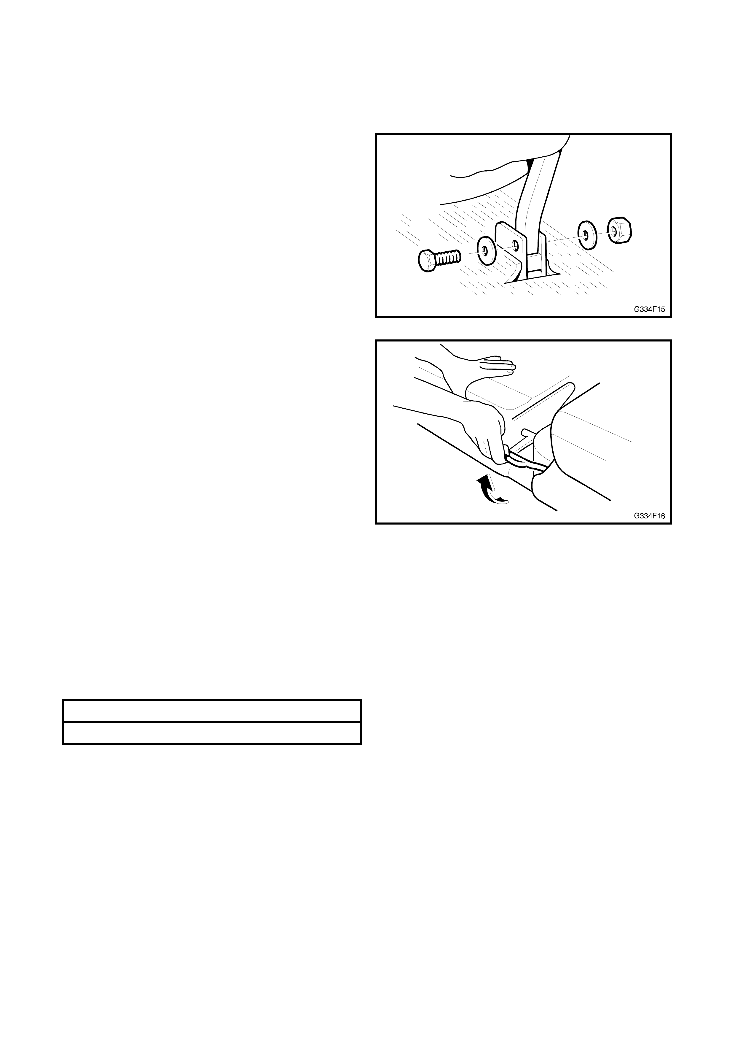
2. Remove the wagon 3rd seat front leg mount bolts.
Figure 4F-15
3. Lift the wagon 3rd seat catch handle, raise the
seat slightly to clear the strikers and remove the
seat.
NOTE: This operation should be performed by two
people.
Figure 4F-16
INSTALL
1. W ith the aid of an assistant, locate the wagon 3rd
seat into the fr ont pivot mounts and insert the M8
bolts, washers and ‘Nyloc’ nuts. Do not over
tighten the nuts.
2. Lock the seat down onto the rear catches.
3. If required, make adjustments to the striker
positions.
4. Tighten all bolts to specified torque.
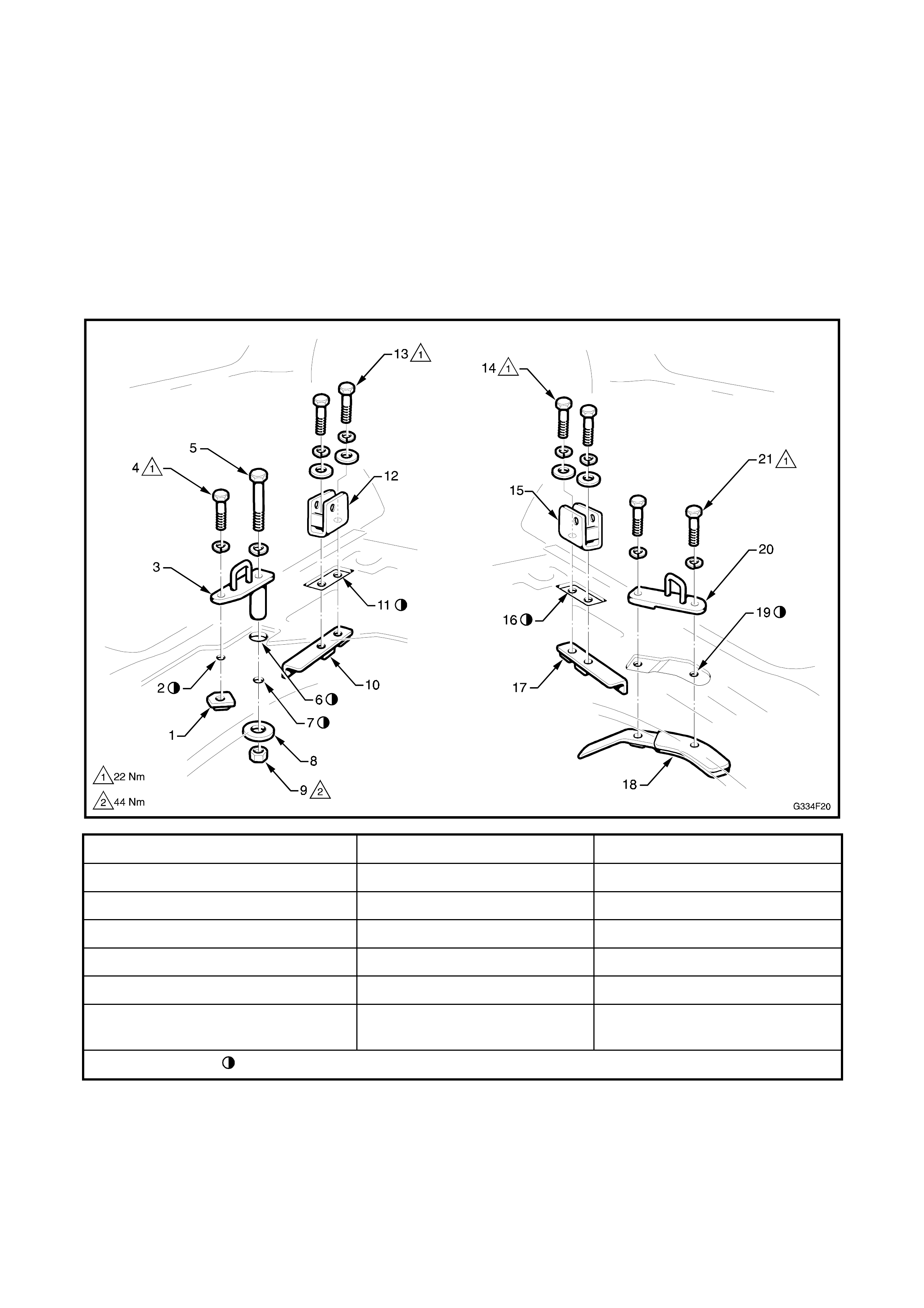
M8 BOLTS 22Nm
M10 BOLTS 44Nm
4.3 REAR FLOOR TRIM
REMOVE
1. Remove the wagon 3r
d
seat as previously
described.
2. Remove the two fir tree fasteners from the rear
compartment floor trim.
3. Remove floor trim, lifting it over the 3rd seat pivot
mounts and striker plates.
INSTALL
1. If the original rear floor trim is being used,
proceed to Step 10.
2. Lay the previously constructed template on the
underside of the rear floor trim, aligning the
markings around the edge, or if no template has
been constructed, refer to 4.7 SEAT MOUNT
MARKING - FLOOR TRIM in this Section.
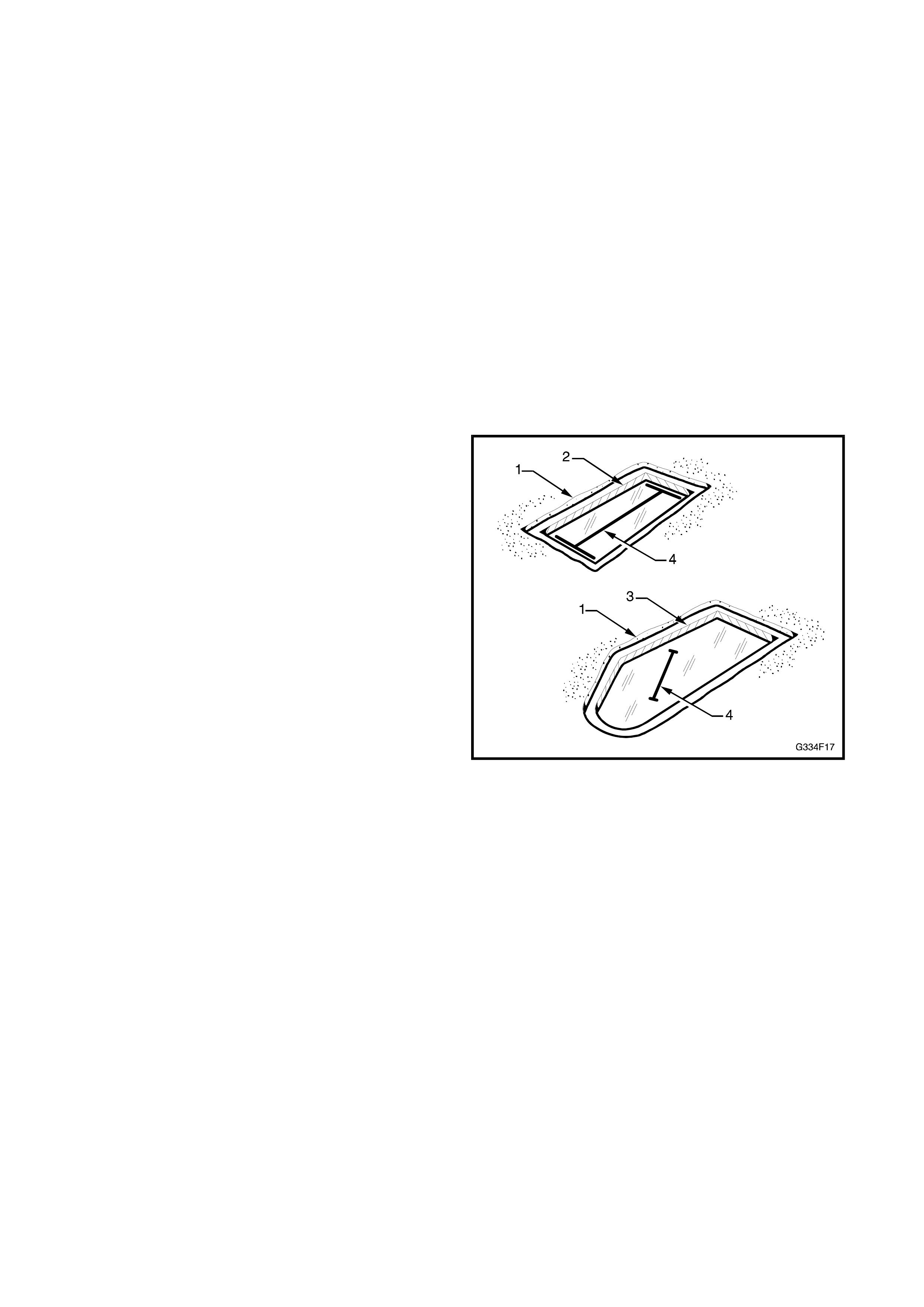
3. Mark the positions required to remove the
underfelt (1).
Figure 4F-17
4. Temporarily remove the template and using a
sharp knife, cut and remove the underfelt.
5. Replace the template and mark the cut out
locations on the wood (2) and plastic (3).
6. Remove the template.
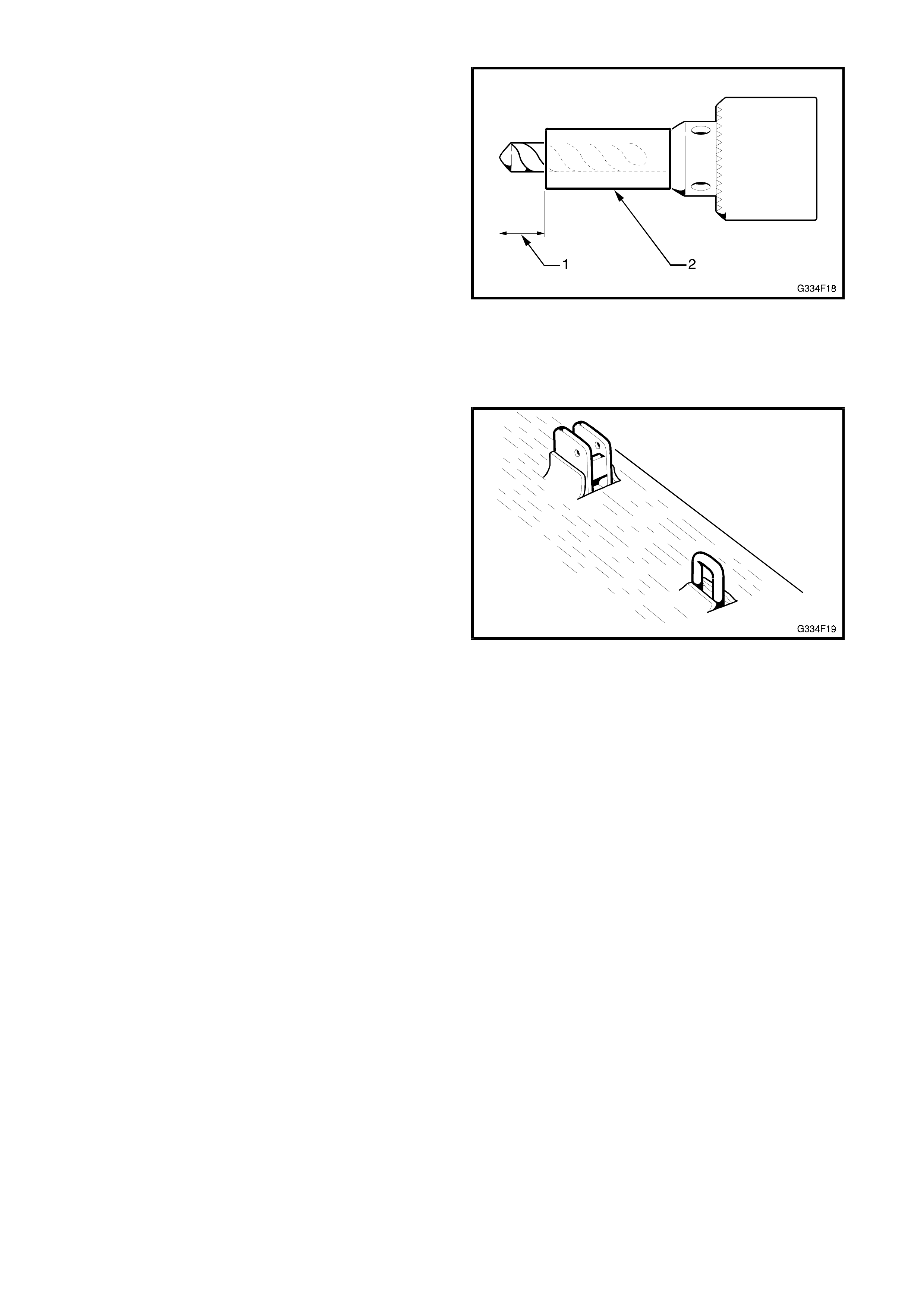
7. Using a 3 mm drill fitted with a spacer to limit
drilling depth (1), carefully drill around the
perim eter of the cut outs in the floor trim . A length
of snug fitting tubing (2) will suffice as the spacer.
NOTE: Do not drill through the carpet.
Figure 4F-18
8. Using a chisel, carefully cut around the perimeter
of the cut outs and remove the wood / plastic
pieces.
NOTE: The wood / plastic is glued to the carpet.
9. While a hole can be cut in the carpet to
accommodate the mountings, the preferred
method is to slit the carpet as shown (4) in Fig.
4F-17, and allow it to fold up around the mounts.
Then if the wagon 3rd seat mounts are ever
removed, the carpet can be folded back to fill the
holes.
Figure 4F-19
10. Install the rear floor trim ensuring neat protrusion
of the wagon 3rd seat pivot mountings and striker
plates.
11. Insert the two fir tree fasteners.
4.4 WAGON 3RD SEAT MOUNTINGS
REMOVE
1. As required, remove the seat pivot mounts and
striker plates as shown in Fig. 4F-20.
NOTE: To gain access to the nut plates for the LH
pivot mount and striker plate, lower the rear muffler.
For V8 and supercharged V6 models, remove the
three LH support rubbers from the intermediate
muf fler assem bly. Allow the exhaust to hang from the
RH outboard bumper r ubber and support the m ufflers
with a transmission jack or similar.
Fi
g
ure 4F-20
1. LH striker nut plate 8. Large washer 15. RH pivot mount
2. 8.5 mm hole 9. M10 Nyloc nut 16. 8.5 mm hole (2 places)
3. LH striker 10. LH pivot mount nut plate 17. RH pivot mount nut plate
4. M8 bolt 11. 8.5 mm hole (2 places) 18. RH striker nut plate
5. M10 bolt 12. LH pivot mount 19. 8.5 mm hole (2 places)
6. 19 mm hole (through floor only) 13. M8 bolt (2 places) 20. RH striker
7. 10.5 mm hole (through
longitudinal) 14. M8 bolt (2 places) 21. M8 bolt (2 places)
Coat bare metal with primer and seal holes with caulking compound
INSTALL
NOTE: If the original mounting holes were
undisturbed, proceed to Step 12.
1. Place the previously constructed template on the
floor ensuring its correct orientation and
alignment with the four alignm ent holes as shown
in Fig. 4F-14, or if no template has been
constructed, refer to 4.6 SEAT MOUNT
MARKING - FLOOR in this Section.
2. Tape the template in position.
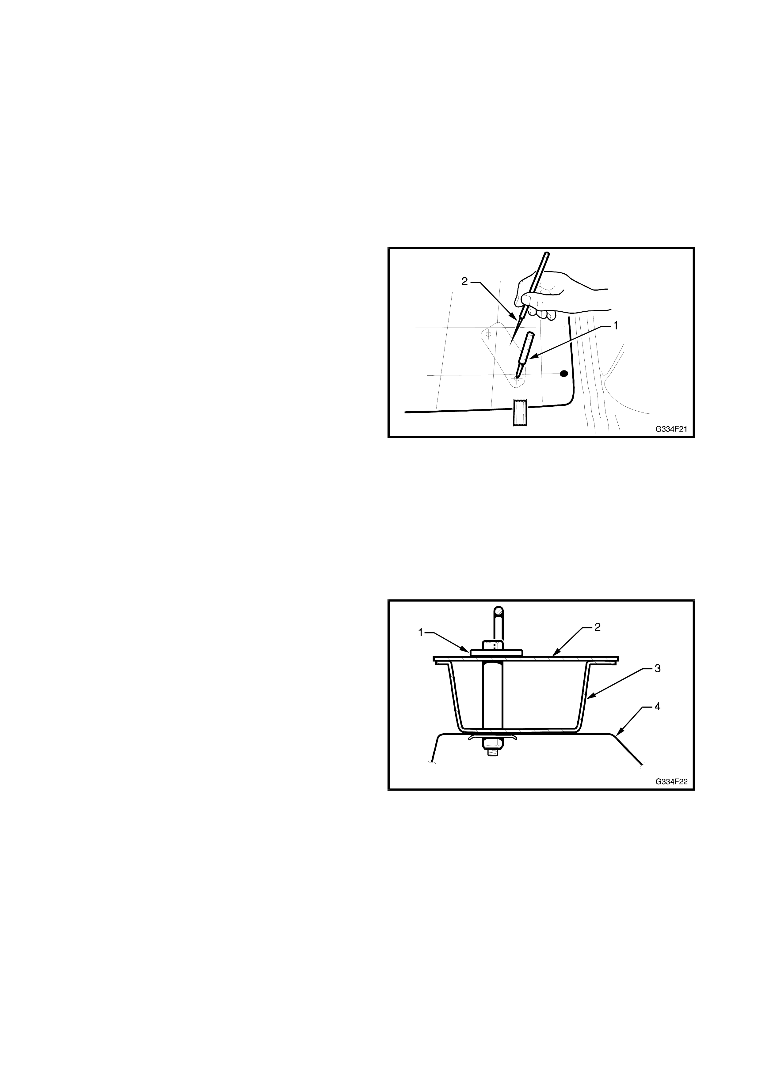
3. Centre punch (1) the desired num ber of m ounting
hole locations through the template onto the floor.
4. If required, scribe a dotted guideline (2) through
the template onto the floor at each pivot mount
and striker location, to outline the deadener
removal areas.
Figure 4F-21
5. Remove the template and drill 3 mm pilot holes
for the eight mounting bolts
IMPORTANT: The RH striker plate is mounted
directly over the fuel tank. To prevent puncturing the
tank, when drilling the RH strik er holes a spacer must
be used over the drill bit to ens ure a m ax imum dr ill tip
length of 25 mm will protrude through the drilled
surf ace. A piece of snug f itting hose will suf fic e as the
spacer. Refer Fig. 4F-18.
6. Drill a 10.5 mm hole at the LH striker (1) front
hole location. Drill through the floor (2),
longitudinal (3) and rear muffler heat shield (4).
Refer to Figs. 4F-20 and 4F-22.
NOTE: It is advisable to use a spacer to achieve a
100-110 mm drill tip depth similar to previously
mentioned, to avoid dr illing into the r ear muf fler. Ref er
to Fig. 4F-17.
Figure 4F-22
7. Enlarge the hole to 19 mm through the FLOOR
ONLY.
8. Drill 8.5 mm holes at all other locations, noting the
fuel tank clearance at the RH striker plate as
previously mentioned.
9. If required, cut the sound deadener along the
dotted guideline (1) as previously marked. The
use of a heat gun will soften the deadener which
can then be carefully scraped from these areas.
Figure 4F-23
10. Vacuum any swarf and removed sound deadener.
The use of a m agnet will assist in c ollecting swarf
from the drilled holes.
11. Coat any bare metal surfaces which may have
been exposed during removal of deadener and
drilling with anti-corrosion primer.
12. Place the mount brackets and plates in their
appropriate locations and insert the appropriate
bolts in each hole. Refer Fig. 4F-20.
13. Raise the vehicle.
14. If required, remove the rear muffler support
rubbers and allow the exhaust to hang as noted at
Step 1.
15. Prior to installing any nut plates and washers,
apply caulking compound to seal the nut plate to
body mating surfaces.
16. With the aid of an assistant, align the front pivot
mount nut plate as shown (1) up to the bolts and
hand tighten the bolts from inside the vehicle.
Figure 4F-24
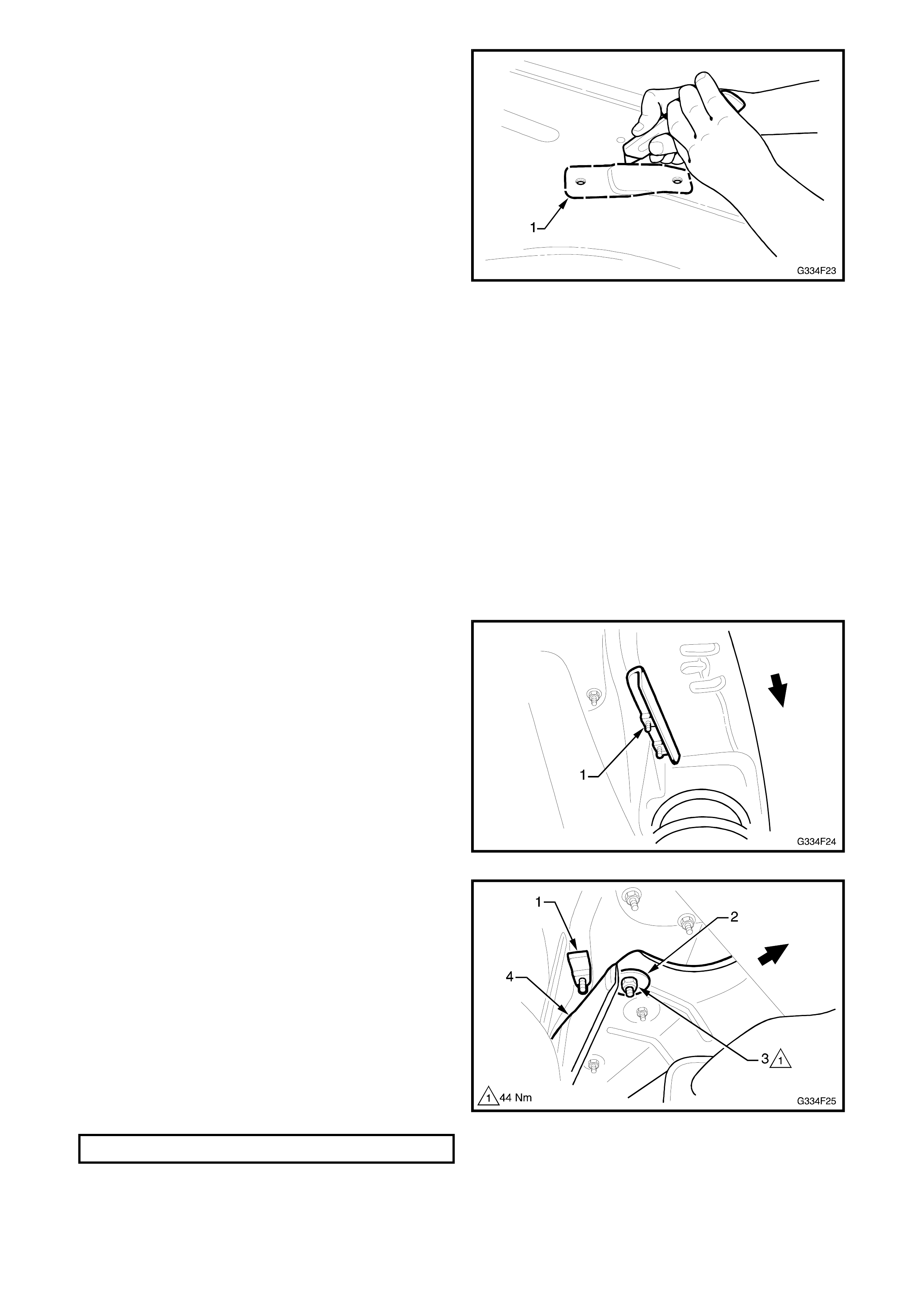
17. Align the LH striker nut plate (1) up to the
rearmost bolt and hand tighten from inside the
car.
18. Install the large washer (2) and Nyloc nut (3) onto
the bolt protruding through the muf fler heat shield
(4).
19. Tighten the bolt until the rib in the heat shield is
crushed flat.
20. Final tighten the nut to the specified torque.
Figure 4F-25
STRIKER PLATE MOUNT BOLT 44Nm

21. Install the RH striker mounting nut plate above
the fuel tank. To assist in aligning the plate, use
an M8 x 45mm seat pivot bolt to ‘catch’ the nut
plate bolt hole. Fit the correct M8 x 30mm bolt
into the other hole and hand tighten. Replace the
M8 x 45m m bolt with the correc t M8 x 30m m bolt
and hand tighten.
22. Install the rear f loor trim and wagon 3rd seat, ref er
4.2 WAGON 3rd SEAT in this Section.
4.5 STORAGE STRAP
REMOVE
1. Remove the rear seat cushion, LH rear seat side
bolster and LH rear seat backrest. Refer Section
1A-7 SEAT & SEATBELT ASSEMBLIES of the
VT Series I Service Information.
2. Remove the pan head screw, washer and nut
attaching the storage strap and remove.
INSTALL
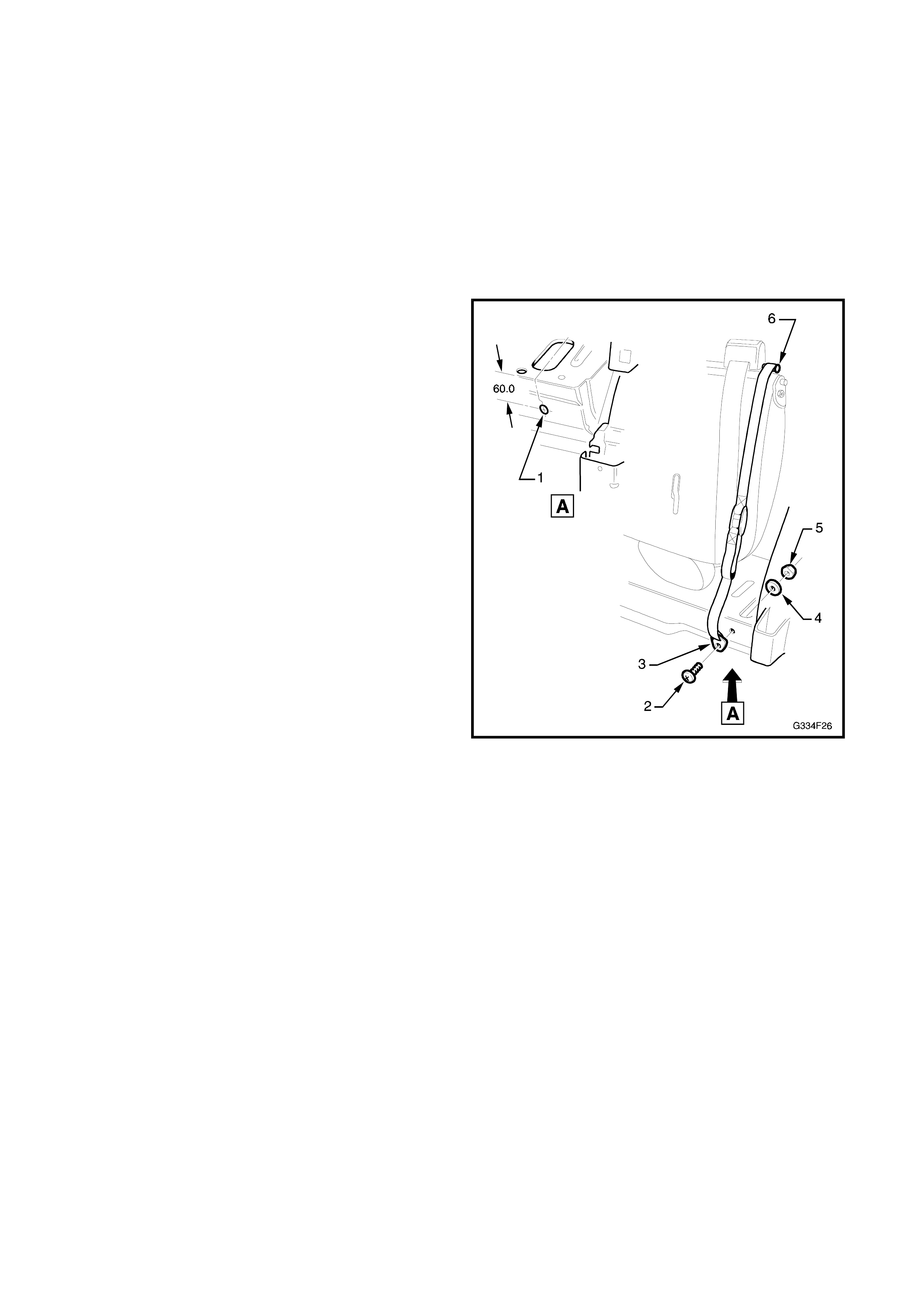
1. Mark and drill an 8.5 mm diameter hole (1), 60
mm below floorpan level as shown.
2. Ins tall the pan head s c rew (2) through the s tor age
strap anchor plate (3) and drilled hole.
3. Attach the washer (4) and nut (5) and tighten.
4. With the 3rd seat backrest folded and the seat
tilted forward, the strap hooks onto the storage
pin.
Figure 4F-26
5. Reinstall rear seat components as described
Section 1A-7 SEAT & SEATBELT
ASSEMBLIES of the VT Series I Service
Information.
4.6 WAGON 3RD SEAT MOUNT MARKING - FLOOR
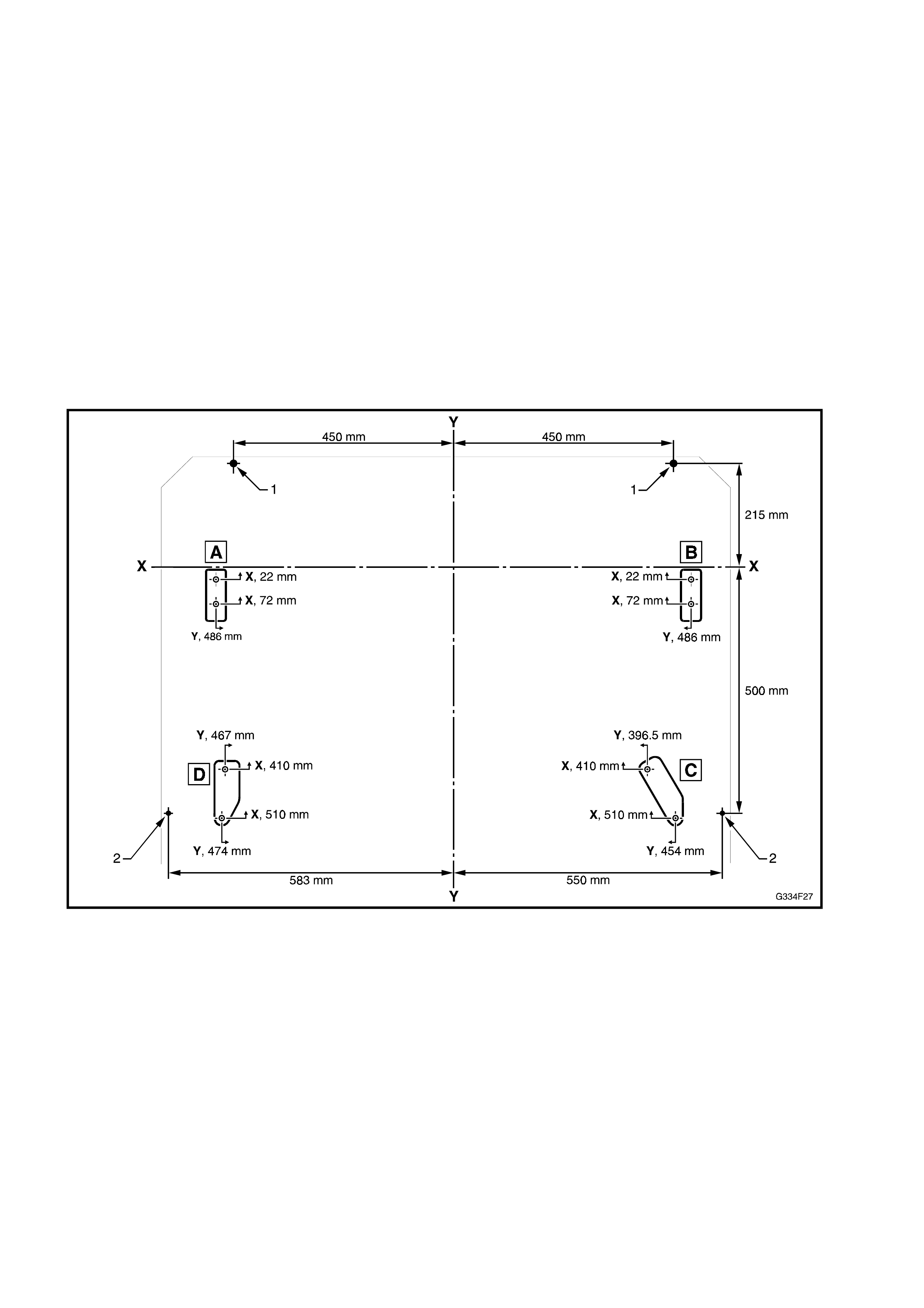
1. Measure the centre of the alignment holes (1) and mark the floor. Refer to Fig. 4F-27 and 4F-14.
2. Measure between the alignment holes (2) as shown.
3. Draw centre line Y, between marks.
4. Measure 215 mm rearward from each alignment hole (1).
5. Mark datum line X along marks.
6. Measure and mark the mount hole centres from the X and Y lines as shown.
7. Drill the mount holes as detailed in 4.4 WAGON 3rd SEAT MOUNTINGS - INSTALL in this Section.
8. Mark the deadener removal areas A, B, C, D by placing each seat mount in position and marking around
the circumference.
9. Using a sharp knife as shown in 4.4 WAGON 3rd SEAT MOUNTINGS - INSTALL in this Section, cut and
remove the deadener.
10. Continue assem bling the 3rd s eat m ountings as detailed in 4.4 WAGON 3rd SEAT M OUNTING S - INSTALL
in this Section.
Figure 4F-27

4.7 WAGON 3RD SEAT MOUNT MARKING - FLOOR TRIM
1. F rom the under side of the rear floor trim , m ark the c entre line Y, by meas uring the centre of the fir trim clip
holes (1) and across the rear end of the trim. Refer Fig. 4F-28.
2. Mark a datum line X through the centre of each fir trim clip hole (1), as shown.
3. Mark the centre of each seat mount on the trim as shown A, B, C, D in Fig. 4F-28.
4. Copy or trace the mount point templates A, B, C & D from Figs. 4F-28 & 4F-29.
5. Align the templates with their corresponding centre mark on the floor trim.
6. Continue mar king and cutting the underf elt ( 2), mas onite or plas tic bac k ing ( 3) and c arpet s lits (4) as shown
in Fig 4F-28, refer 4.3 REAR FLOOR TRIM - INSTALL in this Section for the procedures.
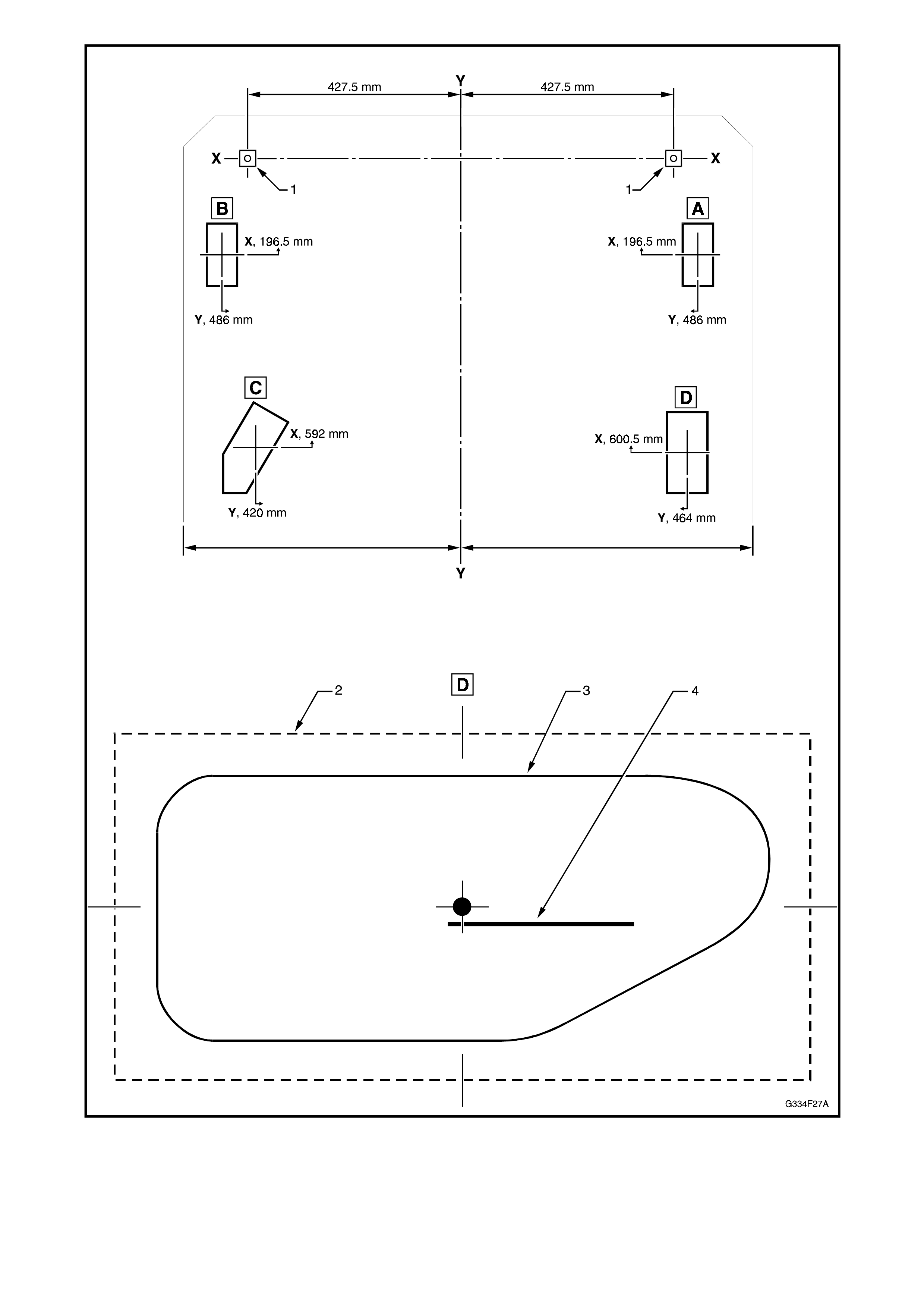
Figure 4F-28
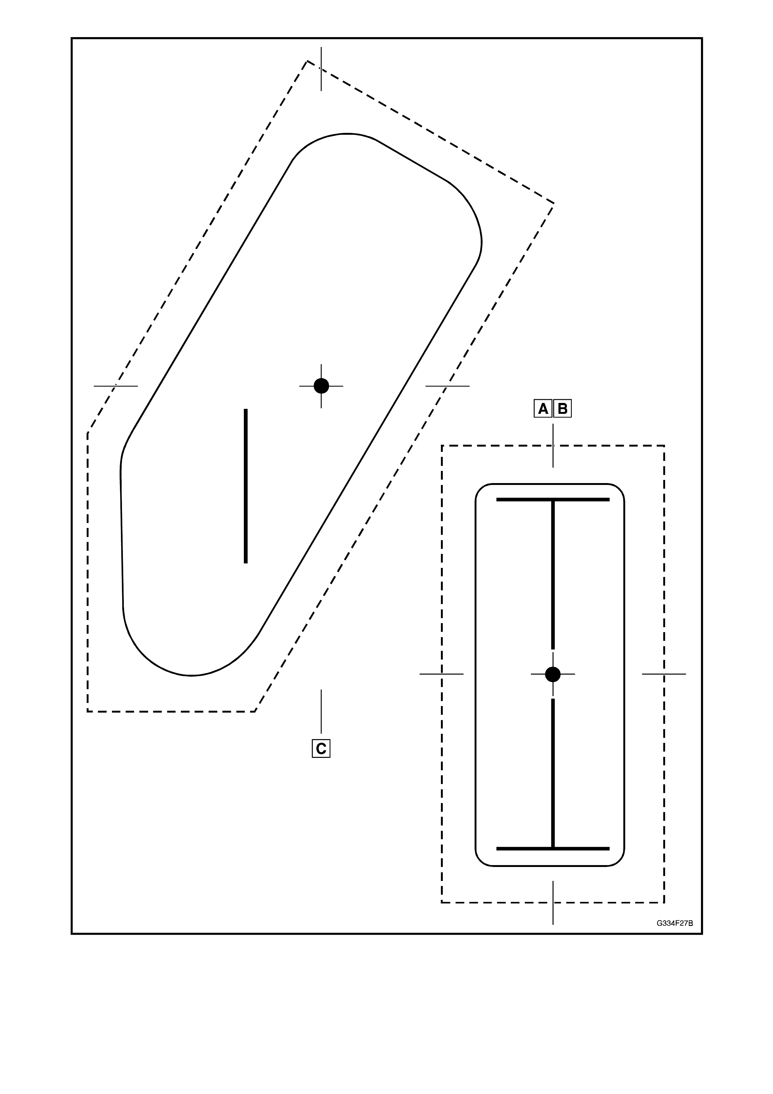
Figure 4F-29
5. LEVEL RIDE SUSPENSION
This section of the Holden By Design Service Information Supplement describes the service procedures for the
level ride system components only. For suspension component service procedures not contained herein, refer to
Section 4, REAR SUSPENSION of the VT Series I Service Information.
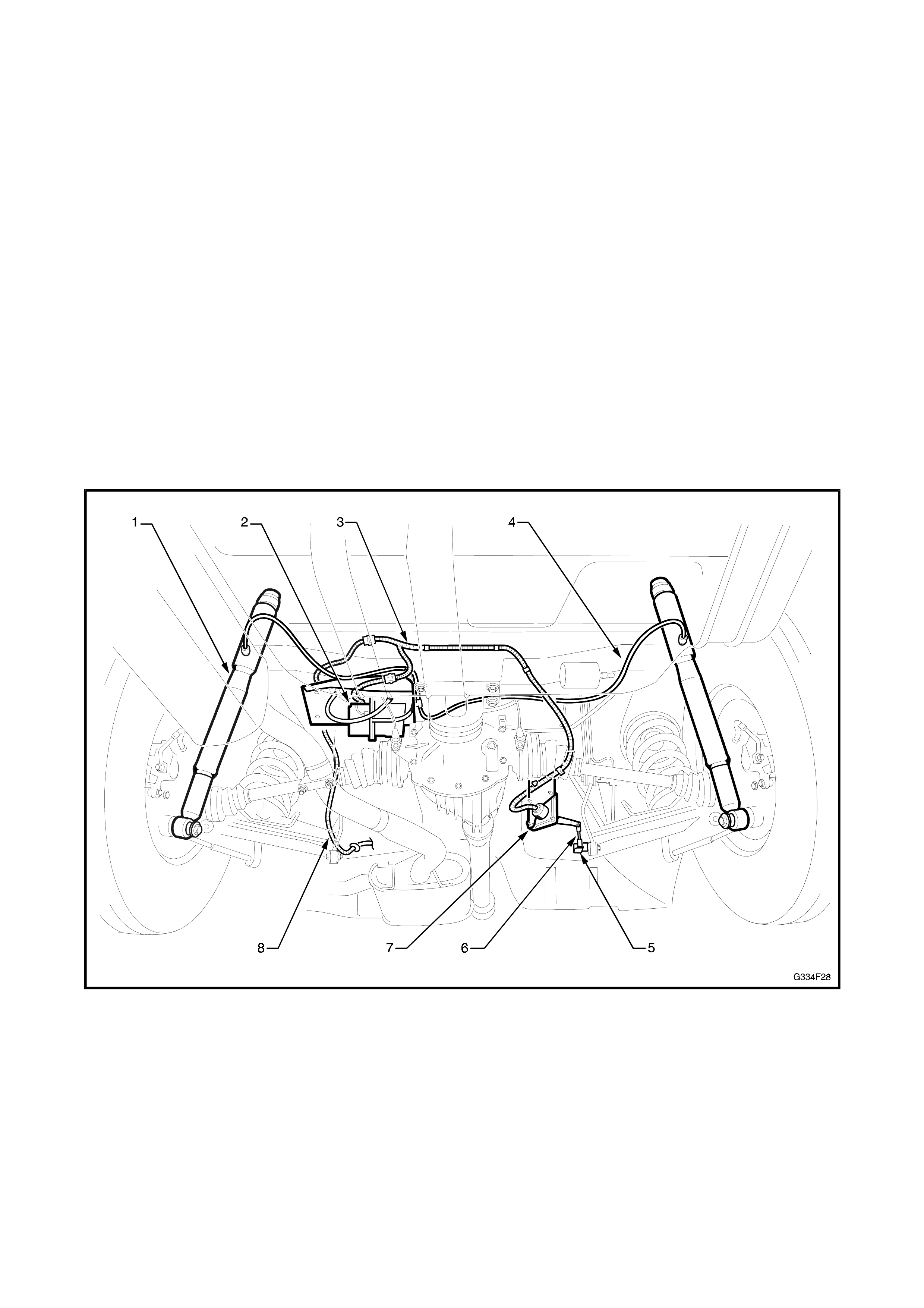
5.1 GENERAL DESCRIPTION
The Holden By Design level ride suspens ion is an electr onic ally controlled s ystem which maintains the vehic le at
a constant ride height, regardless of load. The main components of the sy stem as shown in Fig. 4F-30 are:
• Rear superlift air shock absorbers (1);
• Compressor assembly (2) mounted to the floorpan above the LH drive shaft and incorporating an electric
mo tor, single cylinder air c ompres sor, air exhaust s olenoid valve, maxim um pr essure release valve and an
air dryer;
• Level ride wiring harness (3);
• Air l ines (4);
• Ride height sensor (7) mounted to the rear suspension crossmember and connected to the suspension
trailing arm via a connecting link (6) and ball stud plate (5);
• Patch wiring harness (8) which may be routed along the RH side on some vehicles.
A control relay is also fitted and is located in the passenger compartment fuse and relay panel assembly.
Figure 4F-30
The ride height sensor is attached to the RH suspension trailing arm via the connecting link. A different length
link is used for sedan and wagon variants. Incorporated within the sensor is an electronic controller which is
programmed to adjust ride height, when required, by operating the air compressor or air exhaust solenoid valve.
The compressor supplies the necessary air pressure to an air bag in each rear superlift shock absorber via
flexible air lines. The superlift shock absorbers assist the rear springs in supporting the vehicle body under all
loads.
Level ride is designed to operate only when the sensor detects a change in ride height for a period of 17-20
seconds, ignoring normal suspension movement.
All air entering or exhausting the system flows through the air dryer, which also incorporates a minimum air
pressure retention valve.

This prevents each superlift shock absorber’s air bag completely exhausting, which can lead to air bag damage.
Level Ride control is operational at all times while the ignition is on. A safeguard is provided to prevent the
battery from discharging if, for example, there is an air leak and the compressor is continually running.
Power is supplied via the patch harness which is routed between the level ride harness and the passenger
compartment fuse and relay panel assembly.
IMPORTANT: If air pressure is lost from the system while the vehicle is in service (an air leak f or exam ple) the
super lift shock absorber air bag will most likely become damaged, necessitating replacement.

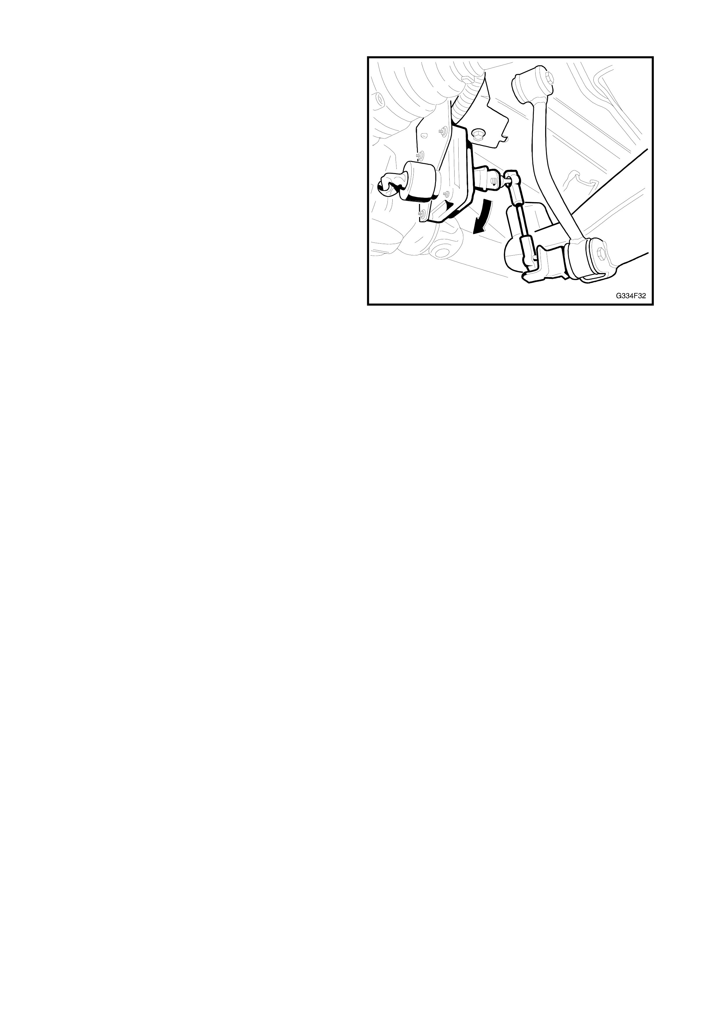
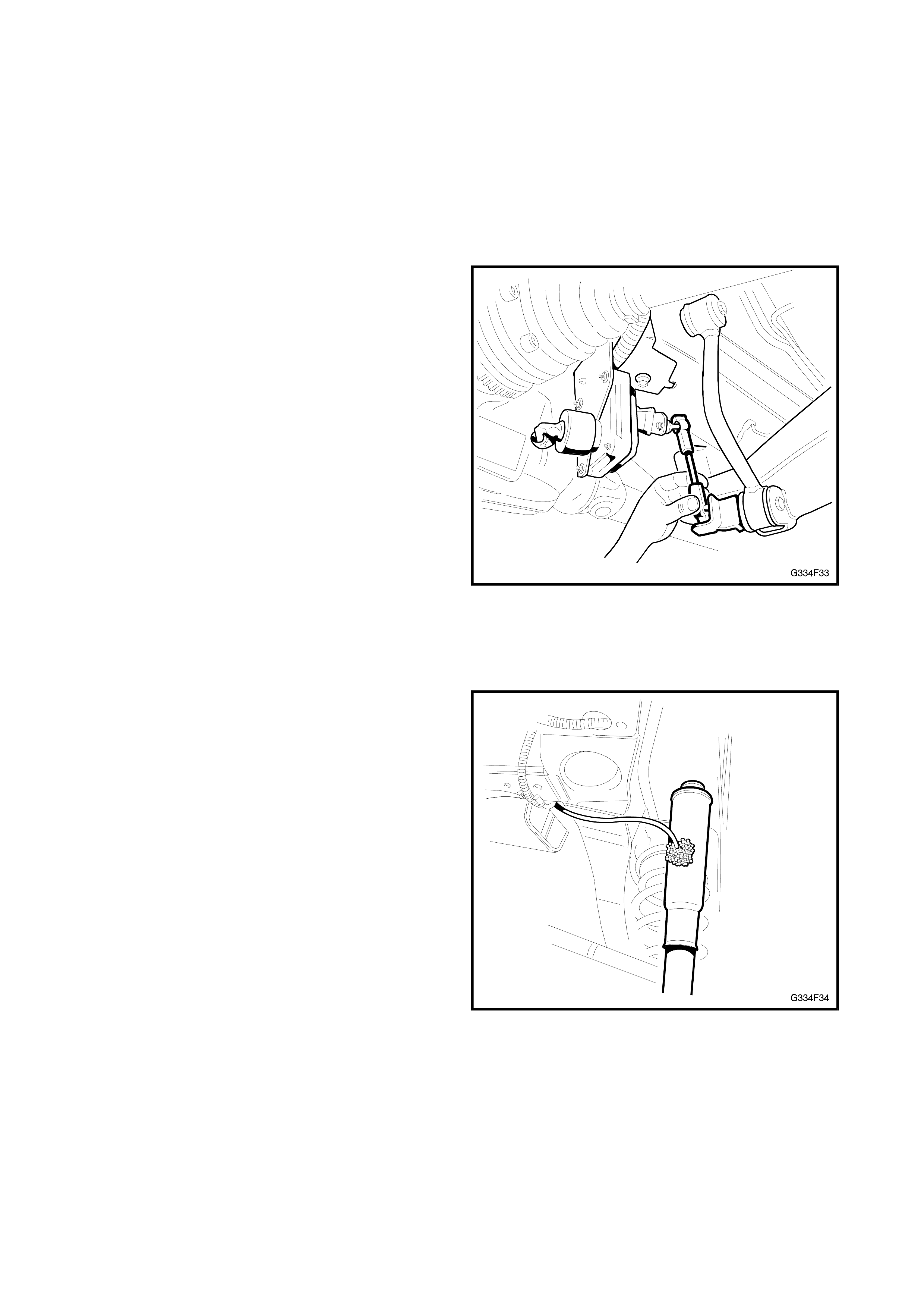
5.2 SYSTEM OPERATION
ACTIVATION
The sensor’s actuating arm (1) is attached to the
lower control arm (2) via the connecting link (3).
Figure 4F-31
Before any activation can occur, the actuating arm
must remain in either the intake zone (A) or exhaust
zone (B), for a continuous 17 to 20 s econds . The time
delay prevents the compressor or exhaust valve from
activating during normal suspension movement.
The sensor also has a ‘deadband’ zone (C) which
helps minimise hunting by deactivating the
compressor and solenoid when the vehicle trims into
the deadband zone or onto one of its edges.
Figure 4F-32
LOADED VEHICLE
When the vehicle is loaded, the body moves
downward causing the actuating arm to move upward
into the intake zone.
After 17 to 20 seconds in this position, the sensor
relieves the compressor head pressure by briefly
activating the relay. The compressor starts, and
pressurises the superlift air shock absorbers until the
vehicle body rises, causing the actuating arm to lower.
When the arm aligns with the top edge of the
deadband zone, the compressor is shut off.
Figure 4F-33
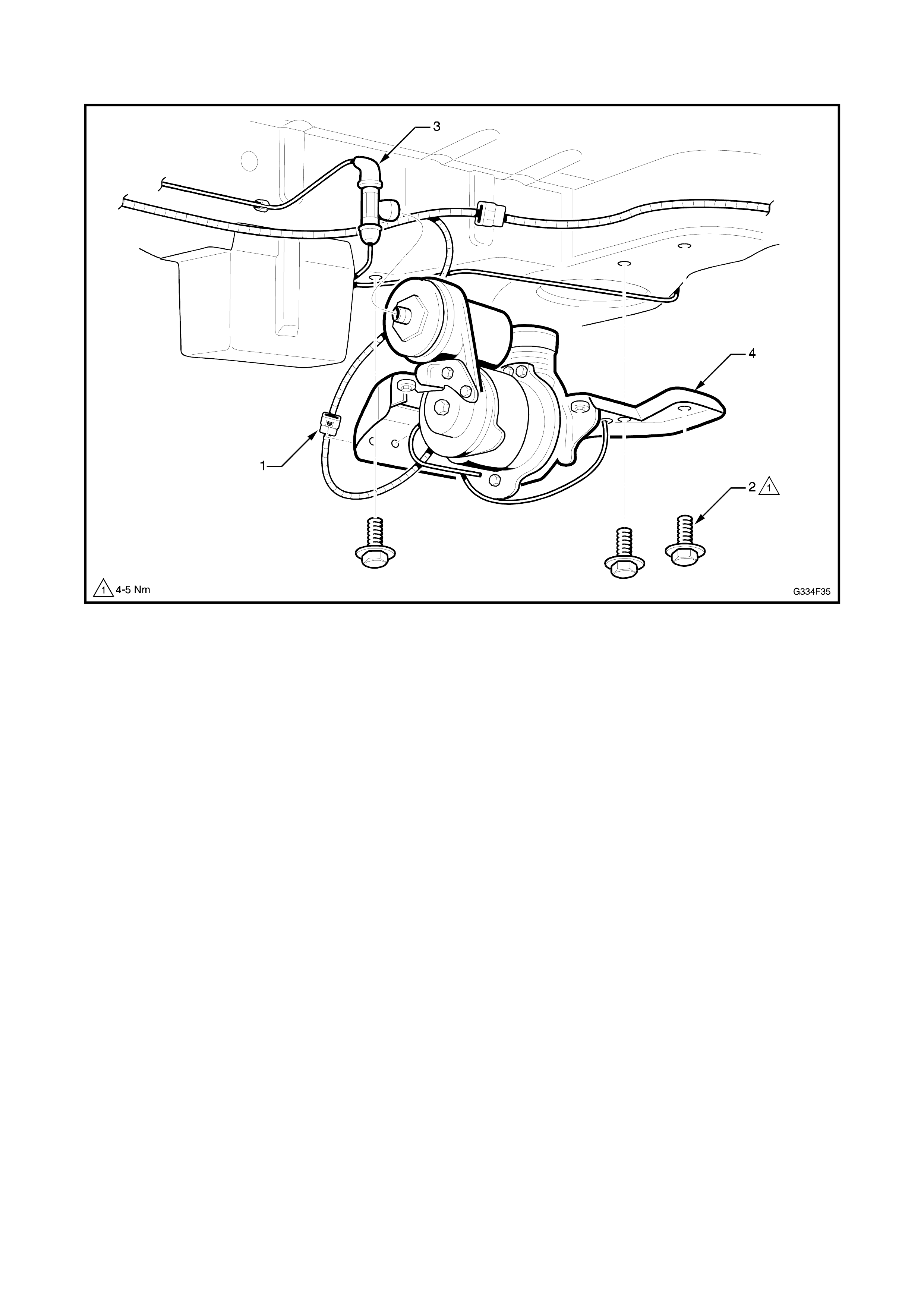
UNLOADED VEHICLE
When the vehicle is unloaded, the body moves
upward causing the actuating arm to m ove downward
into the exhaust zone. After 17 to 20 seconds in this
position, the sensor activates the relay. The exhaust
solenoid activates and vents air from the superlift
shock absorbers until the vehicle body lowers,
causing the actuating arm to rise. When the arm
aligns with the lower edge of the deadband zone, the
solenoid is deactivated.
Figure 4F-34
DEACTIVATION
The compressor and exhaust solenoid operations are
monitored and controlled by individual, but
interconnected, timers. The timers deactivate specific
trimming operations under the following conditions:
• If the compressor operates for m ore than four and
a half minutes, the compressor timer deactivates
all system operations.
• If the exhaus t solenoid is operational f or m ore than
four and a half minutes the solenoid timer
deactivates the solenoid.
NOTE: No further operation of these components can
take place until the timers are reset.
RESET
1. Turn the ignition on.
2. Turn the ignition off for one minute.
3. Turn the ignition on.

5.3 MAINTENANCE
The level ride system has been designed to be virtually maintenance free. However at each scheduled service,
the following components must be inspected and rectified if found to be faulty.
AIR LINES
Inspect the air lines for rubbing or f ouling with the body and other components. Ensure the lines are not kinked
and that they are fitted into the retaining clips. Check the connections for correct fit.
WIRING HARNESS
Inspect the wiring harness for rubbing or fouling with the body and other com ponents. Ensure that it is f itted and
secured into the retaining clips and/or cable ties. Check the connections for correct fit.
AIR FILTER
The compressor air filter should be replaced at the 30,000 km and 70,000 km service intervals, and every
40,000 km thereafter. Inspect and replace more frequently if required, where the vehicle is driven in dusty
conditions.
5.4 SERVICE OPERATIONS
IMPORTANT: If air pressure in the level ride system
is lost during service procedures, do not lower the
vehicle until system pressure has been restored as
damage will most likely result. Charge the system as
explained below.
INITIAL AIR CHARGE
1. Turn the ignition on.
2. Disconnect the lower end of the sensor
connecting link.
3. Push the sensor arm upward, above the
horizontal plane for 20 seconds to activate the
compressor.
4. Leave the compressor running for approximately
30 seconds to inflate the superlift shock
absorbers.
5. Turn the ignition off.
6. Check the system for leaks.
7. Reconnect the sensor connecting link.
Figure 4F-35
AIR LEAK TEST
1. Ensure the system is pressurised. Refer to
INITIAL AIR CHARGE procedure if required.
2. Star ting at the shock abs orber connections, apply
a foaming leak check solution (commercially
available, or a soap solution mixed with water) to
all fittings and connections.
3. Carefully inspect the fittings and connections for
the presence of air bubbles in the solution.
4. Repair any detected leaks as required.
5. Retest the system for air leaks.
6. If air still leaks from the system, isolate sections
of the system until the source of the leak is found.
7. Clean off the residual solution.
Figure 4F-36
COMPRESSOR ASSEMBLY
Figure 4F-37
REMOVE
1. Disconnect the battery, negative lead first.
2. Raise the vehicle.
3. Unclip the level ride wiring harness (1) from the
compressor assembly mounting bracket and
disconnect the wiring connector, refer Fig. 4F-37.
4. Remove the three bolts (2) attaching the
compressor assembly mounting bracket to the
vehicle body.
NOTE: Support the compressor assembly. Do not
allow it to drop.
5. Disconnect the airline T-connector (3) from the
compressor by rotating the T-piece 90 degrees,
then gently pulling it away from the compressor.
6. Lower the compressor assembly.
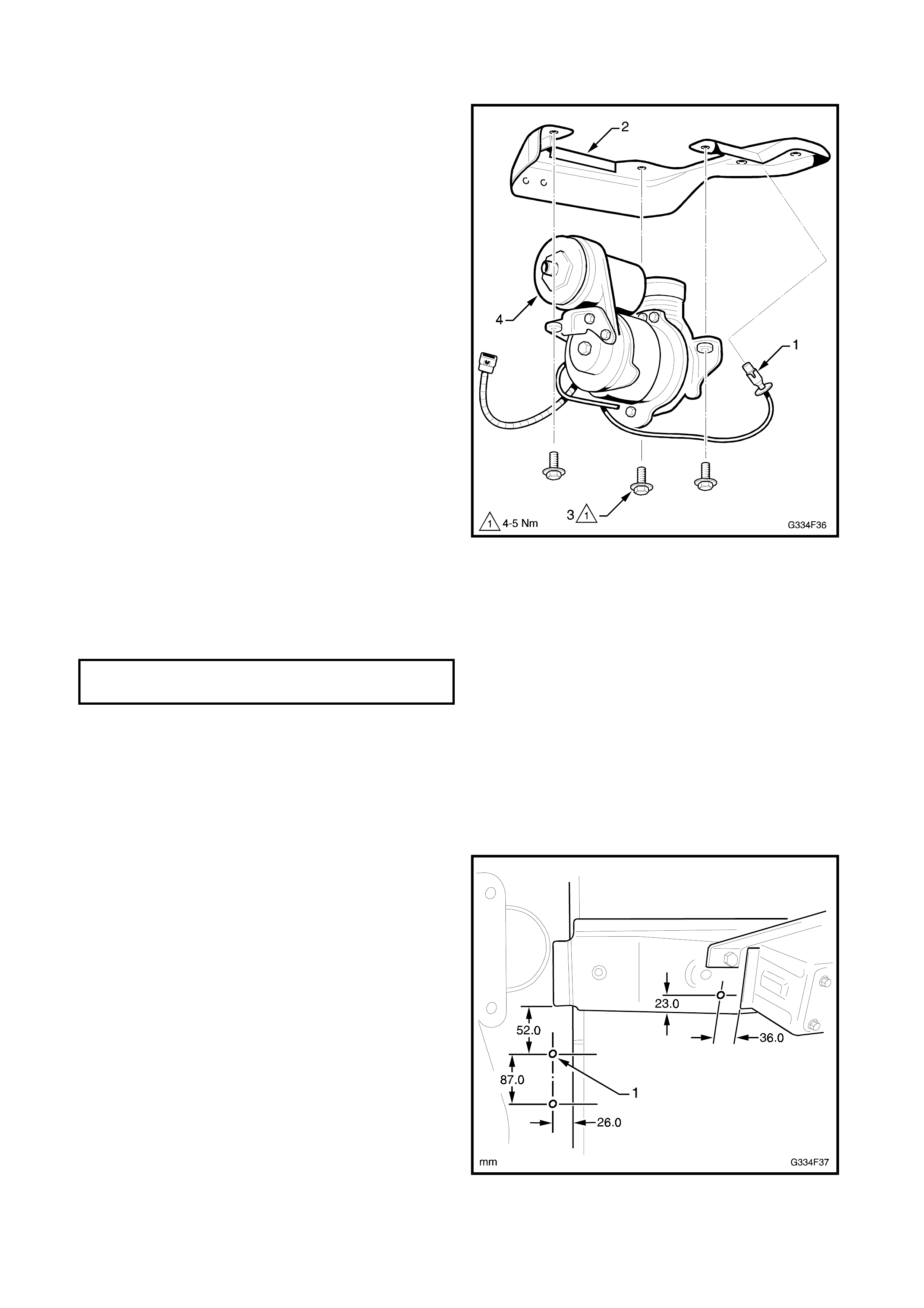
DISASSEMBLE
1. Remove the filter (1) from the mounting bracket
(2).
2. Remove the three bolts (3) attaching the
compressor (4) to the mounting bracket.
Figure 4F-38
REASSEMBLE
1. Install the components in the reverse order to
disassembly.
2. Tighten the bolts to the specified torque.
COMPRESSOR MOUNTING
BOLTS 4-5 Nm
NOTE: Test the filter is clean and free from
restric tions by rem oving the filter and blowing through
it from the hose connection end. If any restriction is
felt, replace the filter.
INSTALL
1. If the LH rear longitudinal and/or crossmember
has been replaced, compressor assembly
mounting holes (1) will have to be drilled as
required.
Figure 4F-39
2. Bring the compressor assembly up to the air line
and connect the T-piece.
NOTE: Ensur e the airline is c or rec tly routed, placed in
all of its mounting clips and does not foul with, or rub
against any components or body fittings.
3. Install the three mounting bolts and tighten to the
specified torque.
COMPRESSOR ASSEMBLY
MOUNTING BOLTS 4-5 Nm
4. Connect the wiring harness connector and clip the
harness into position.
NOTE: Ensure the harness is correc tly routed, placed
in all of its m ounting clips/ties and does not foul with,
or rub against any components or body fittings.
5. Connect the battery.
NOTE: Do not completely lower the vehicle until
system air pressure has been reinstated.
6. Charge the system with air as described in
INITIAL AIR CHARGE in this Section.
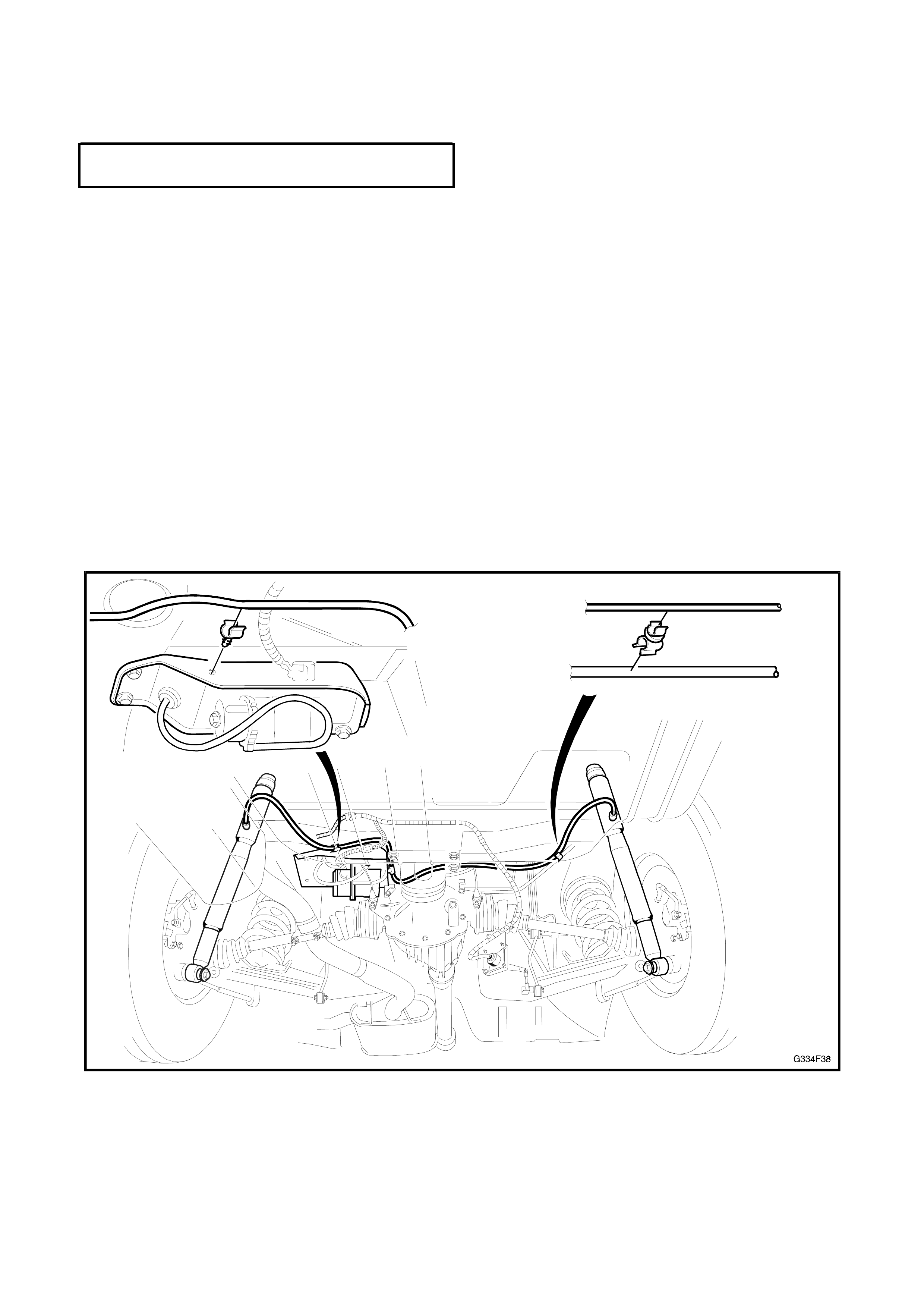
AIR LINES
The air lines are routed between the com pressor and
each shock absorber. Retaining clips are placed
along each line to secure the air line to the vehicle.
Either screw-on type or clip-on type connectors are
used to attach the air line to the s hoc k abs or bers , and
a clip-on T-piece attaches the air lines to the
compressor.
Figure 4F-40
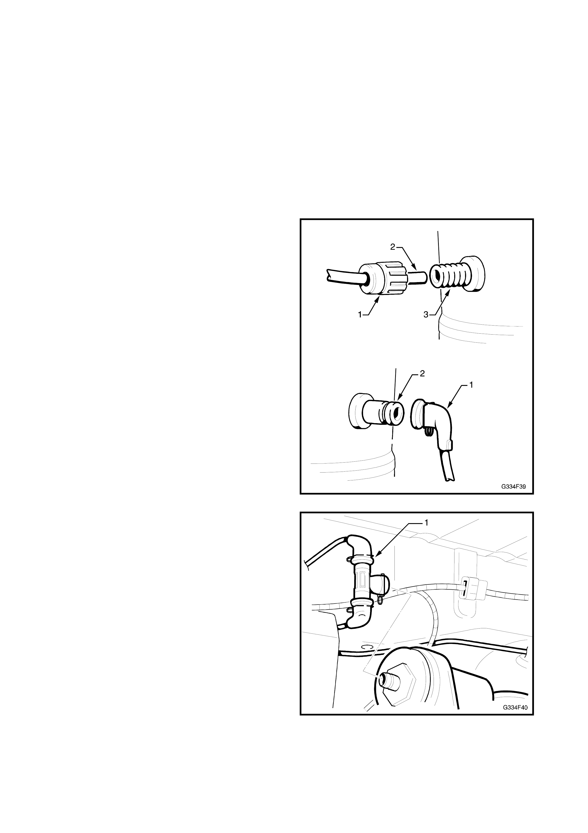
REMOVE
Screw-on type
1. Carefully unscrew the connector from the
component and remove air line.
Clip-on type
1. Rotate the connection 90 degrees, then carefully
pull the connector and air line away from the
component.
INSTALL
1. Route the airline in the retainers ensuring there
are no kinks and it does not foul on the body or
any components.
Shock absorber screw-on connection.
1. Fit the connection cap (1) onto the air line (2).
2. Insert the air line into the shock absorber port (3).
3. Slide the cap along the air line and screw it onto
the shock absorber fitting.
NOTE: Do not over tighten.
Shock absorber clip-on connection.
1. Push the connection cap (1) onto the shock
absorber port (2).
Figure 4F-41
Compressor connection
1. Fit each air line connection onto the T-piece (1).
2. Push the T-piece onto the compressor fitting,
ensuring it is secure.
3. Charge the system with air and test for air leaks
as detailed in INITIAL AIR CHARGE in this
Section.
Figure 4F-42
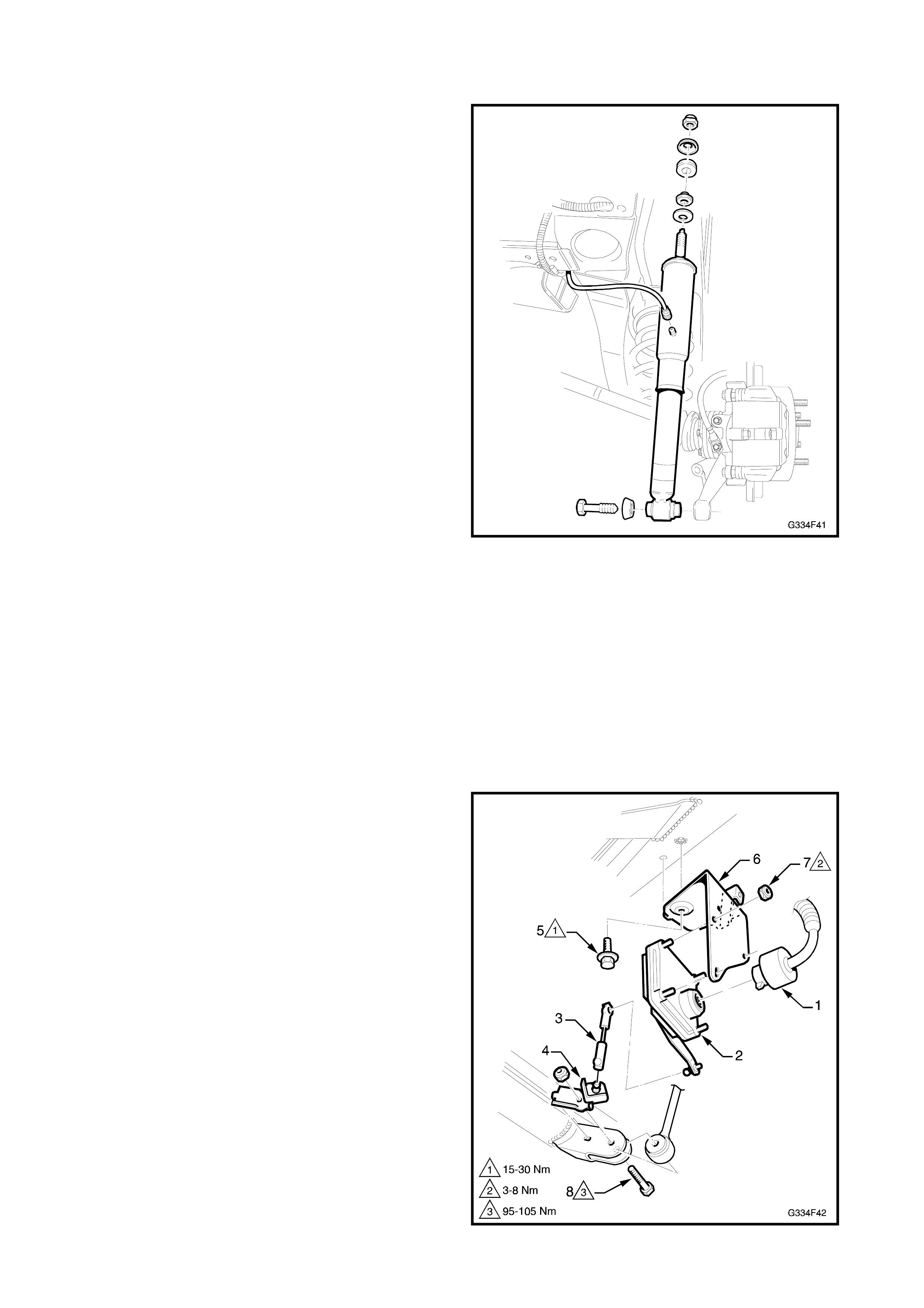
SHOCK ABSORBER
Removal and installation of the superlift air shock
absorbers is the same as standard shock absorbers
with the exception of the following. Refer to Section
4, REAR SUSPENSION in the VT Series I Service
Information for shock absorber removal and
installation.
REMOVE
1. Dis connect the air line connection f rom the s hock
absorber by unscrewing the connection cap. Also
refer to Fig. 4F-41.
INSTALL
1. Connect the air line to the shock absorber as
detailed in AIR LINES; Shock Absorber
Connection in this Section.
NOTE: Face the connection forward on sedan models
and inboard on wagon models.
2. Charge the system with air as detailed in INITIAL
AIR CHARGE in this Section.
3. Check the system for air leaks.
Figure 4F-43
HEIGHT SENSOR
NOTE: The position of the height sensor is critical to
the level ride system’s operation. A bent or damaged
mounting bracket, connecting link or ball stud plate, or
incorrect installation of the sensor and components
can be cause of incorrect operation.
REMOVE
1. Disconnect the battery, negative lead first.
2. Unclip or cut the cable ties securing the sensor
wiring harness to the sensor bracket.
3. Disconnect the wiring harness connector (1) from
the sensor (2).
4. Disconnect the sensor link (3) from either the
sensor arm or ball stud plate (4).
5. While holding the sensor assembly, remove the
bolt (5) attaching the s ensor m ounting br acket (6)
to the crossmember.
6. Remove the sensor assembly.
7. If required, remove the nuts (7) attaching the
sensor to the mounting bracket.
8. If required, remove the bolt (8) attaching the ball
stud plate to the trailing arm.
Figure 4F-44
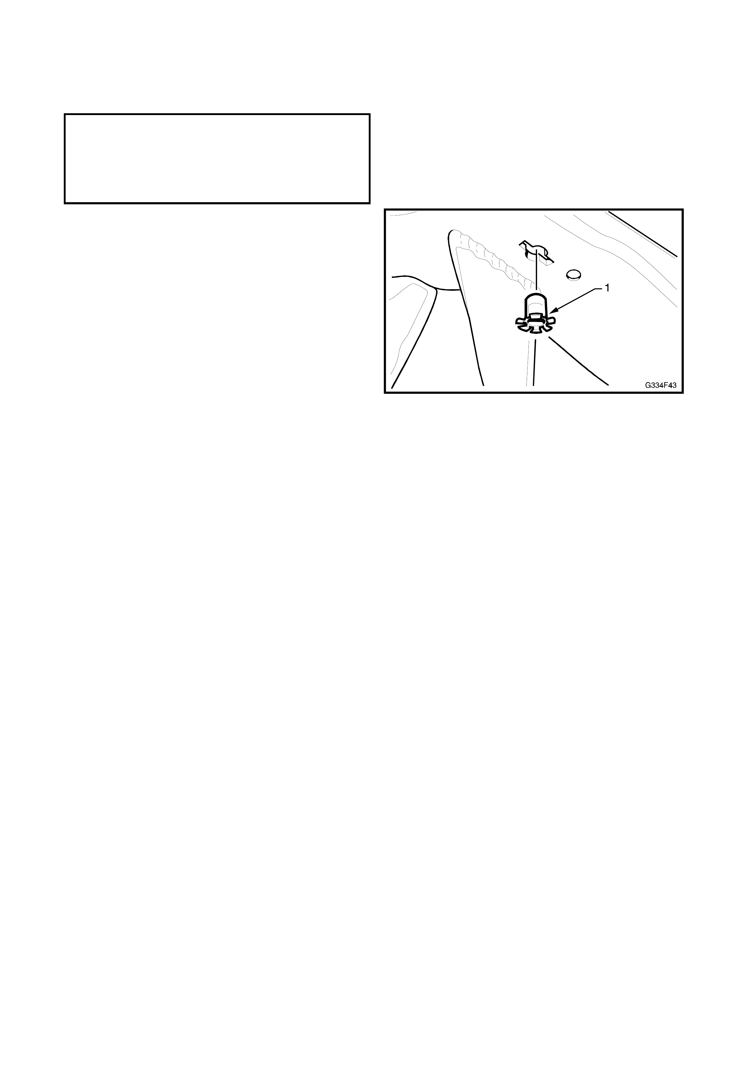
INSTALL
1. Install the components in the reverse order to
removal to the specified torque.
SENSOR BRACKET TO
CROSSMEMBER BOLT 15-30 Nm
SENSOR TO BRACKET NUTS 3-8 Nm
STABILISER BAR LINK BOLT &
NUT 95-105 Nm
NOTE: If the rear suspension c ross m em ber has been
replaced, insert the nut cage (1) into the
crossmember as shown.
Figure 4F-45

5.5 DIAGNOSIS & WIRING
The f ollowing procedur es are des igned to as s ist in the diagnos is of a f ault in the level r ide s ystem. It is impor tant
the technician is fam iliar with the principles of oper ation of the system in or der to accurately identify the problem
prior to proceeding.
The diagnosis tables are to be used in conjunction with the wiring schematic and wiring harness diagrams, in this
Section.
EQUIPMENT
A digital multimeter with a minimum 20 Megohm impedance must be used when undertaking any electrical
checks with this system.
When performing tests on the wiring harness, use the appropriate probe adaptor to ensure the wiring and/or
connectors are not damaged during testing.
RIDE HEIGHT SENSOR RESET
If the compr essor or exhaust solenoid operate for m ore than f our and a half m inutes, the sensor timers mus t be
reset by turning the ignition on, then off for one minute, then on again.
CHART 1 PRELIMINARY DIAGNOSTIC PROCEDURE
STEP ACTION VALUE YES NO
1. Does the vehicle trim? Go to Step 2. Go to Step 3.
2. Does the vehicle trim to the correct height? Refer to 5.6
SPECIFICATION
S in this Volume.
System OK. Check all
suspension
components for
wear & damage,
paying particular
attention to the
height sensor
mounting &
bracket.
3. Does the vehicle rise after the specified
time when the vehicle is loaded?
Place load in the vehicle.
20 seconds. Go to Step 4. Go to Chart 2,
Compressor
Assembly Test-
Motor.
4. Does the vehicle lower after the specified
time when the vehicle is unloaded.
Remove load from the vehicle.
20 seconds System OK. Go to Chart 3,
Compressor
Assembly Test-
Solenoid.

CHART 2 COMPRESSOR ASSEMBLY TEST - MOTOR
STEP ACTION VALUE YES NO
1. Has a system reset been performed? Go to Step 2. Perform sy stem
reset. Refer the
beginning of this
Section.
2. Is fuse FJ OK?
(located in the engine compartment fuse &
relay box)
Go to Step 3. Replace blown
fuse. Check
wiring for the
cause of the
blown fuse. Re-
check system.
3. Are fuses F24 & F15 OK?
(located in the passenger compartment fuse
& relay box)
Go to Step 4. Replace blown
fuse(s). Check
wiring for the
cause of the
blown fuse(s).
Re-check
system.
4. 1. Disconnect the wiring harness at the
level ride sensor.
2. Turn the ignition on.
3. Bridge Pin 3 & Pin 4 in the level ride
sensor connector.
4. Listen for the compressor motor
running, or
Check for voltage between Pins B & D
at the compressor harness connector.
• Motor
running, or
• 12 Volts at
the
compressor
harness
connector
Pins B & D.
Compressor
motor OK.
Proceed to Chart
4, Height Sensor
Test -
Compressor
Operation.
Go to Step 5.
5. Check the wiring harness for continuity. Continuity . Replace the
compressor
assembly. Refer
5.4 in this
Section.
Repair or replace
harness.

CHART 3 COMPRESSOR ASSEMBLY TEST - SOLENOID
STEP ACTION VALUE YES NO
1. Has a system reset been performed? Go to Step 2. Perform sy stem
reset. Refer the
beginning of this
Section.
2. Is fuse FQ OK?
(located in the engine compartment fuse &
relay box)
Go to Step 3. Replace blown
fuse. Check
wiring for the
cause of the
blown fuse. Re-
check system.
3. Are fuses F6 & F15 OK?
(located in the passenger compartment fuse
& relay box)
Go to Step 4. Replace blown
fuse(s). Check
wiring for the
cause of the
blown fuse(s).
Re-check
system
4. 1. Disconnect the wiring harness at the
level ride sensor.
2. Turn the ignition on.
3. Bridge Pin 2 & Pin 4 in the level ride
sensor connector.
4. Listen for a clicking of the solenoid
valve & air escaping from the system,
or
Check for voltage between Pins A & C
at the compressor harness connector.
• Clicking
sound from
the solenoid
& air
escaping or,
• 12 Volts at
the
compressor
harness
connector
Pins A & C.
Compressor
assembly
solenoid OK.
Proceed to Chart
5, Height Sensor
Test - Solenoid
Operation.
Go to Step 5.
5. Check the wiring harness for continuity. Continuity Replace the
compressor
assembly. Refer
5.4 in this
Section.
Repair or replace
the harness.

CHART 4 HEIGHT SENSOR TEST - COMPRESSOR
STEP ACTION VALUE YES NO
1. Has a system reset been performed? Go to Step 2. Perform sy stem
reset. Refer the
beginning of this
Section.
2. 1. Disconnect the height sensor link. Refer
Section 5.4 in this Volume.
2. Turn the ignition on.
3. Raise the height sensor arm 45
Degrees & wait 20 seconds.
4. Listen for the compressor motor
running, or
Check for voltage between Pins B & D
at the compressor harness connector.
• Compressor
motor
running, or
• 12 volts at
pins B & D.
Go to Step 3. Go to Step 6.
3. The compressor motor may be operating
but the compressor may have failed.
Run the motor for 2 minutes & check the
shock absorber air bags are being
pressurised.
Air pressure in
the shock
absorber air
bags.
System OK.
Recheck system
for correct
operation if
necessary.
Go to Step 4.
4. Check the air compressor filter for
blockage. Filter OK. Go to Step 5. Replace filter &
recheck the
system.
5. Check the air lines for correct fitment, kinks
& damage. Air lines OK Replace the
compressor
assembly &
recheck the
system.
Replace air line
& recheck the
system.
6. Check wiring harness for continuity. Continuity. Replace the
height sensor
assembly. Refer
5.4 in this
Section.
Repair or replace
harness.
CHART 5 HEIGHT SENSOR TEST - SOLENOID
STEP ACTION VALUE YES NO
1. Has a system reset been performed? Go to Step 2. Perform sy stem
reset. Refer the
beginning of this
Section.
2. 1. Disconnect the height sensor link. Refer
Section 5.4 in this Volume.
2. Turn the ignition on.
3. Lower the height sensor arm 45
Degrees & wait 20 seconds.
4. Listen for clicking of the solenoid valve
& air escaping from the system, or
Check for voltage between Pins A & C
at the compressor harness connector.
• Clicking
sound from
the solenoid
& air
escaping, or
• 12 volts at
pins A & C.
System OK.
Recheck system
for correct
operation if
necessary.
Go to Step 3.
3Check the wiring harness for continuity. Continuity . Replace the
height sensor
assembly. Refer
5.4 in this
Section.
Repair or replace
harness.
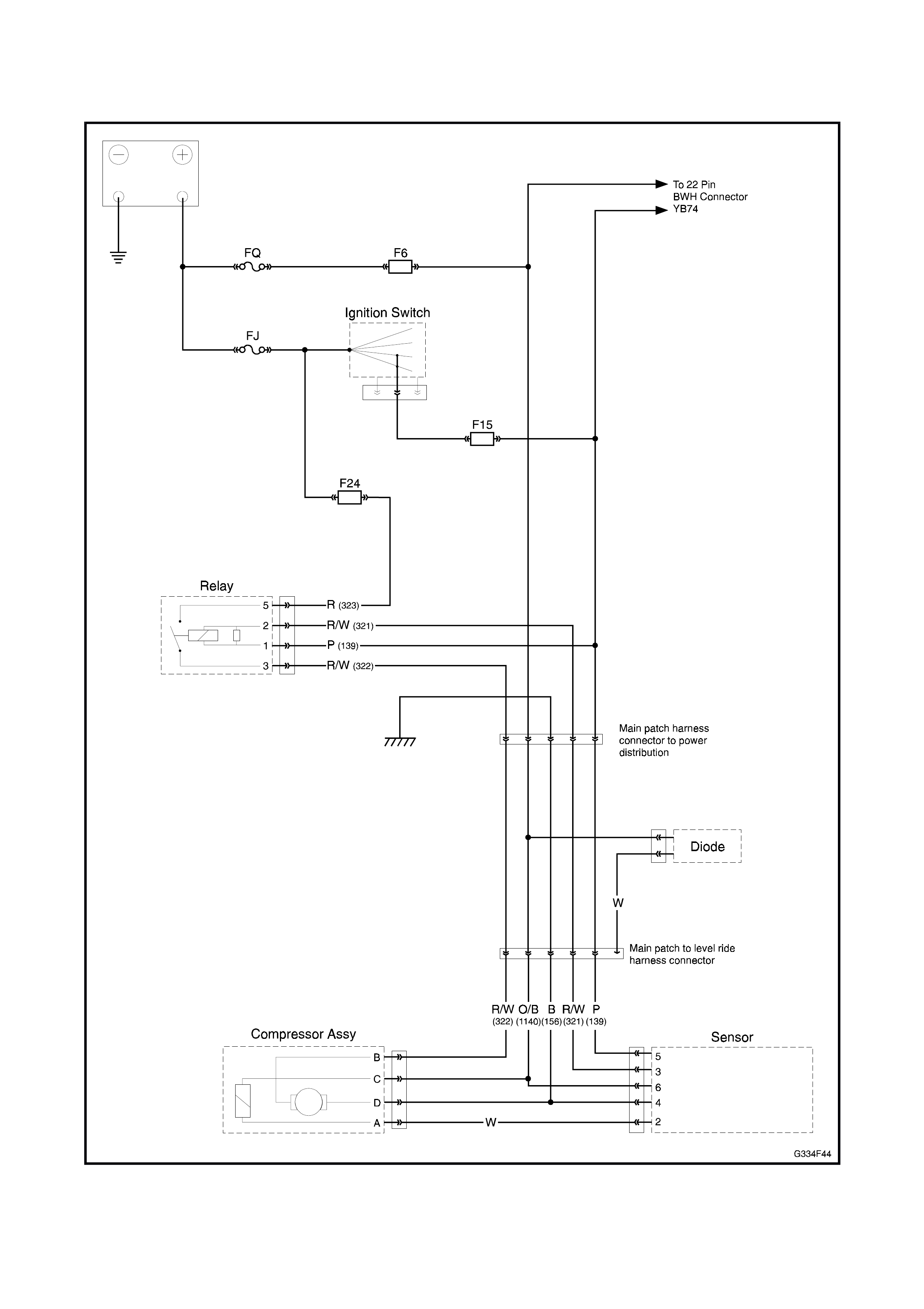
WIRING SCHEMATIC
Figure 4F-46
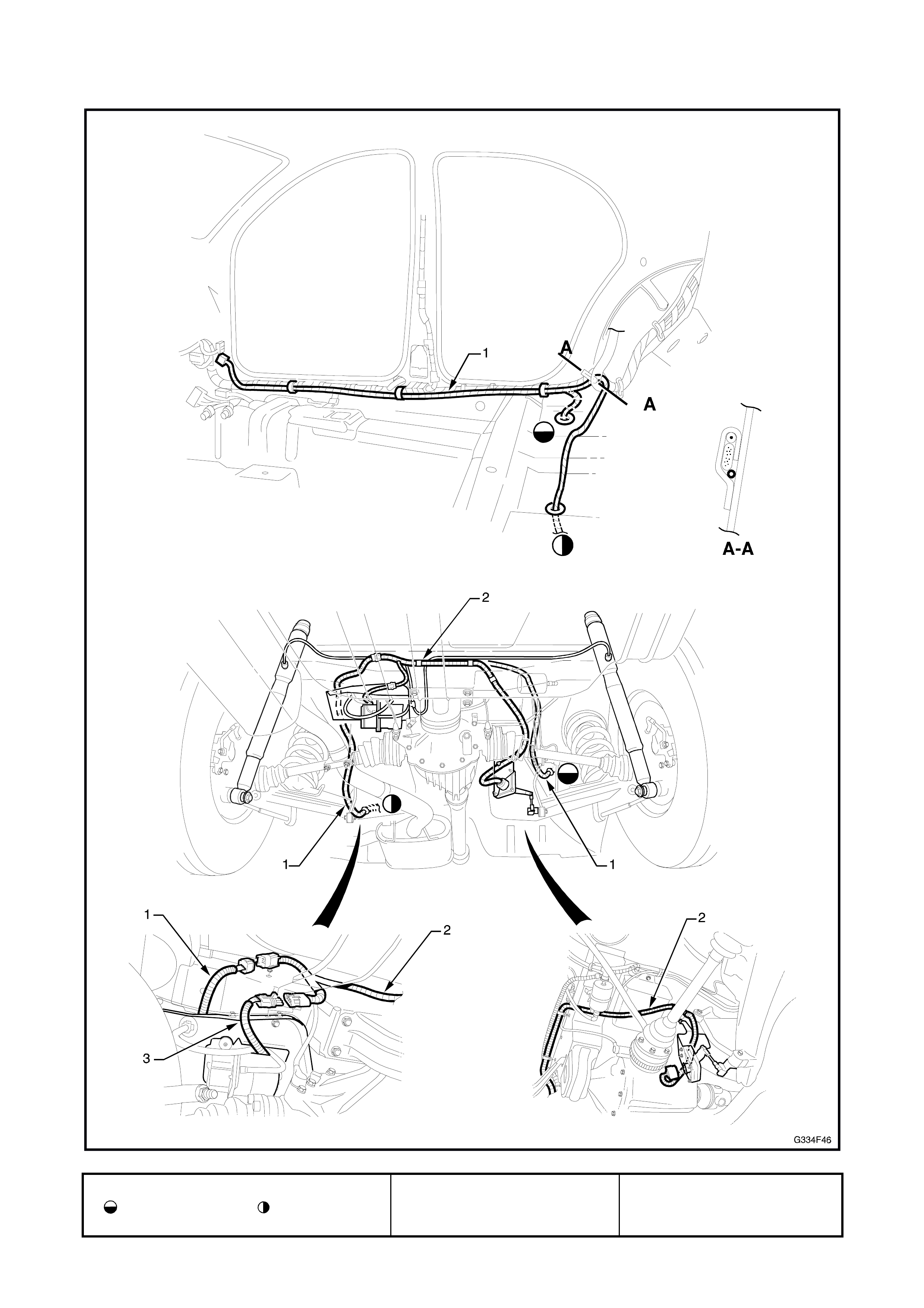
WIRING HARNESS
Figure 4F-47
1. Patch harness
Routed on RH side Routed on LH
side
2. Level ride harness 3. Compressor harness
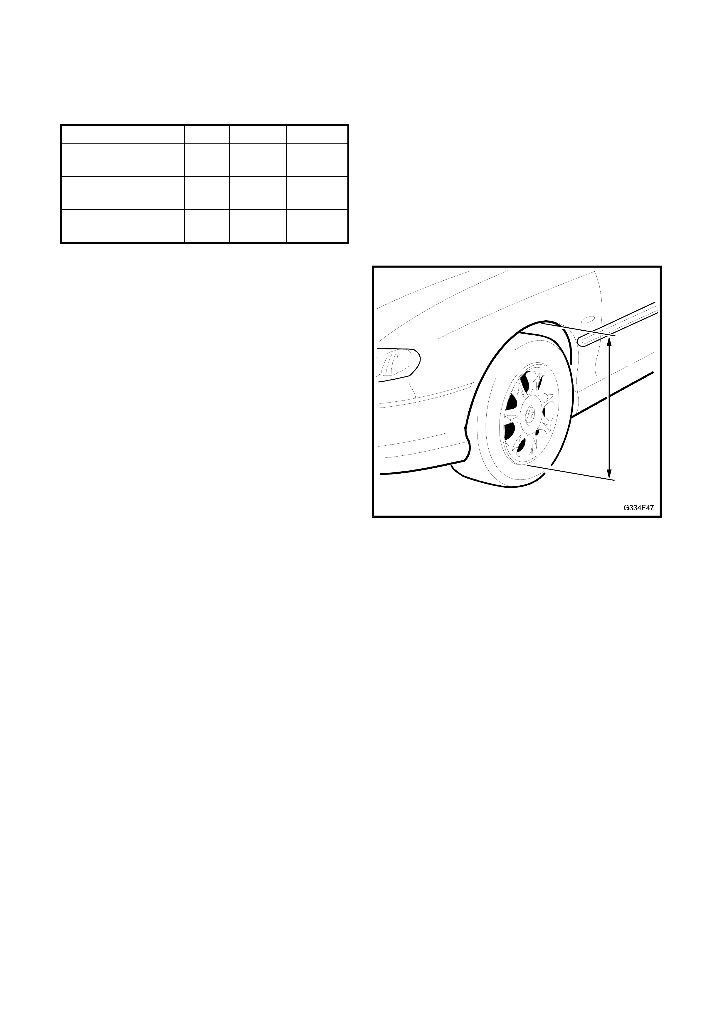
5.6 SPECIFICATIONS
VEHICLE RIDE HEIGHT
MODEL SEDAN WAGON
Executive V6 Manual Front 598 603
Rear 562 573
Berlina V6 Auto Front 603 598
Rear 586 582
Calais V6 Auto Front 609 -
Rear 603 -
NOTE: The table is to be used as a guide only.
Specifications are for a new vehicle with standard
suspension, no options or accessories, no occupants
or luggage and at kerb weight; full tank of fuel, fluids
filled to specified levels and tyres at correct pressure.
Measurements are from the lower edge of the wheel
rim to the lower edge of the wheel arch opening.
Figure 4F-48