SECTION 4G - VT SERIES LPG SYSTEM
CAUTION:
This vehicle will be equipped with a Supplemental Restraint System (SRS). A SRS will consist of
either seat belt pre-tension ers and a driver’s air bag , seat belt pre-t ensioners and a driv er’s and front
passenger’s air bag s or seat belt pre-tensio ners, driver’s and fron t passenger’s air bags and left and
right hand side air bags. Depending upon the system fitted, refer to SAFETY PRECAUTIONS, Section
12M Supplemental Restraint System in the VT Series I Service Information, before performing any
service operation on or around any SRS components, the steering mechanism or wiring. Failure to
follow the SAFETY PRECAUTIONS could result in SRS deployment, resulting in possible personal
injury or unnecessary SRS system repairs.
CAUTION:
This v ehicle may be equipped w ith LPG ( Liquefied Pet roleum Gas). In th e interests of safet y, the LPG
fuel system should be isolated by turning 'OFF' the manual service valve and then draining the LPG
service lines, before any service work is carried out on the vehicle. Refer to the LPG leaflet included
with the Owner's Handbook for details or the VT Series I Service Information for more specific
servicing information.
1. GENERAL INFORMATION
This Section of the Holden By Design Service Information Supplement provides general information for the
components employed in the HBD LPG systems. For information not contained in this Section, refer to the VT
Series I Service Information.
The Holden By Design LPG installation fully integrates with the VT Series electrical, mechanical, engine
management and security systems. Vehicles fitted with the HBD LPG package have revised rear suspension
ensuring correct ride height is maintained and handling is not compromised.
The LPG fuel tank is located in the rear compartment, under the rear parcel shelf for sedan models.
Wagon models utilise a toroidal type fuel tank which is also commonly referred to as a ‘doughnut tank.’ It is
mounted in the spare wheel well necessitating relocation of the spare wheel to the RH side of the cargo area.
Both sedan and wagon HBD LPG systems , locate the fuel m ode switch on the centre cons ole as shown in Figures
4G-1 and 4G-2. HBD LPG vehicles also have a HBD identification plate fitted to the radiator support panel.
All service procedures for the Holden By Design LPG system are contained in the VT Series I Service Information.
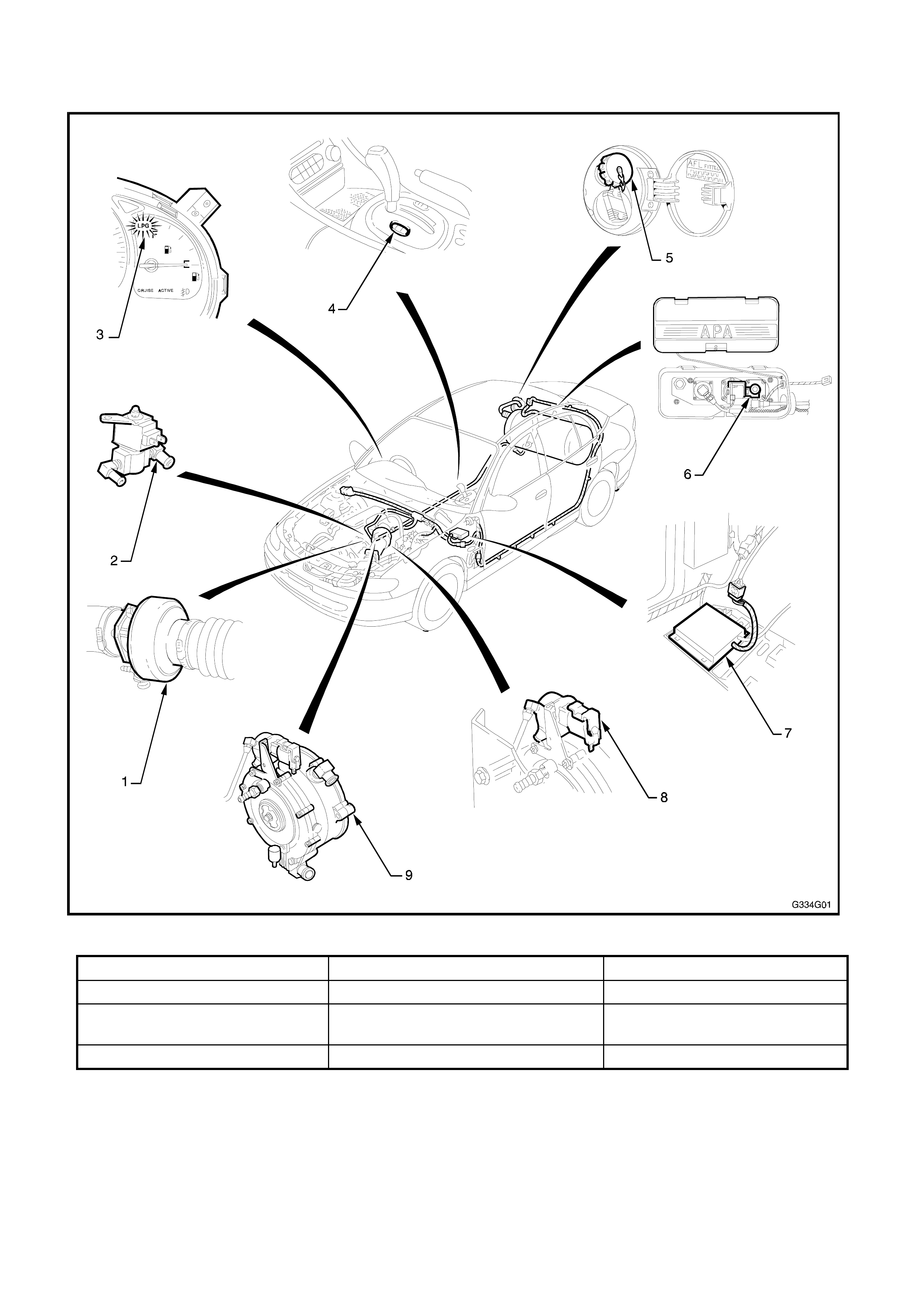
1.1 MAJOR COMPONENTS
Figure 4G-1
1. Mixer 5. Spare wheel carrier 9. LPG lock off
2. Fuel control valve 6. LPG filler valve 10. Converter
3. LPG instrument cluster
lamp 7. Solenoid & Service valve
assy.
4. Fuel mode switch 8. Adaptive digital processor
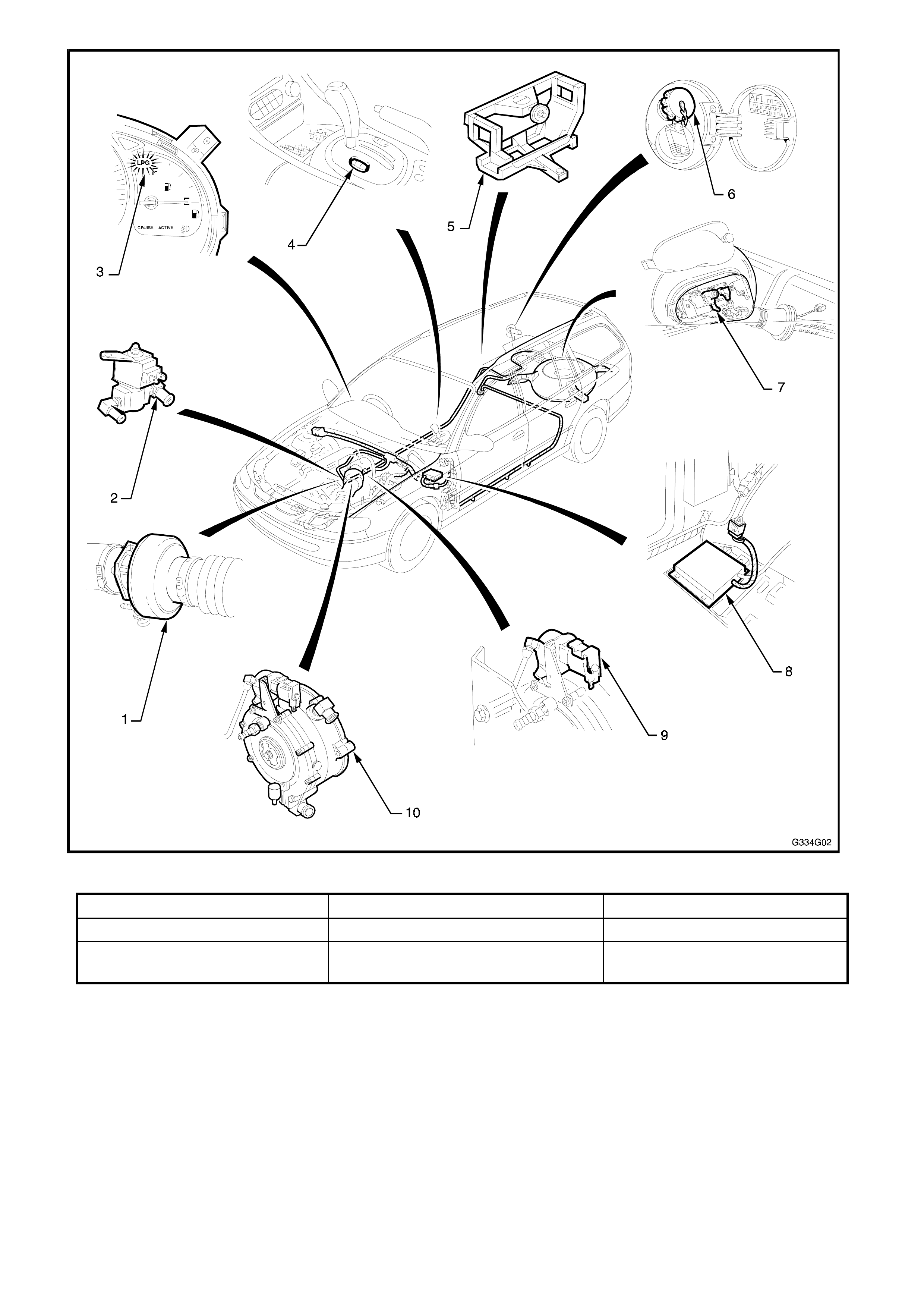
Figure 4G-2
1. Mixer 4. Fuel mode switch 7. Adaptive digital processor
2. Fuel control valve 5. LPG filler valve 8. LPG lock off
3. LPG instrument cluster
lamp 6. Solenoid & Service valve
assy. 9. Converter
2. IDENTIFI CATION & BADGING
When a Holden By Design LPG system is installed,
several identification plates and warning labels are
fitted as shown. NOTE: If the vehicle is repaired or
the components that the labels / plates are attached
to are replaced, the label or plate must also be
replaced.
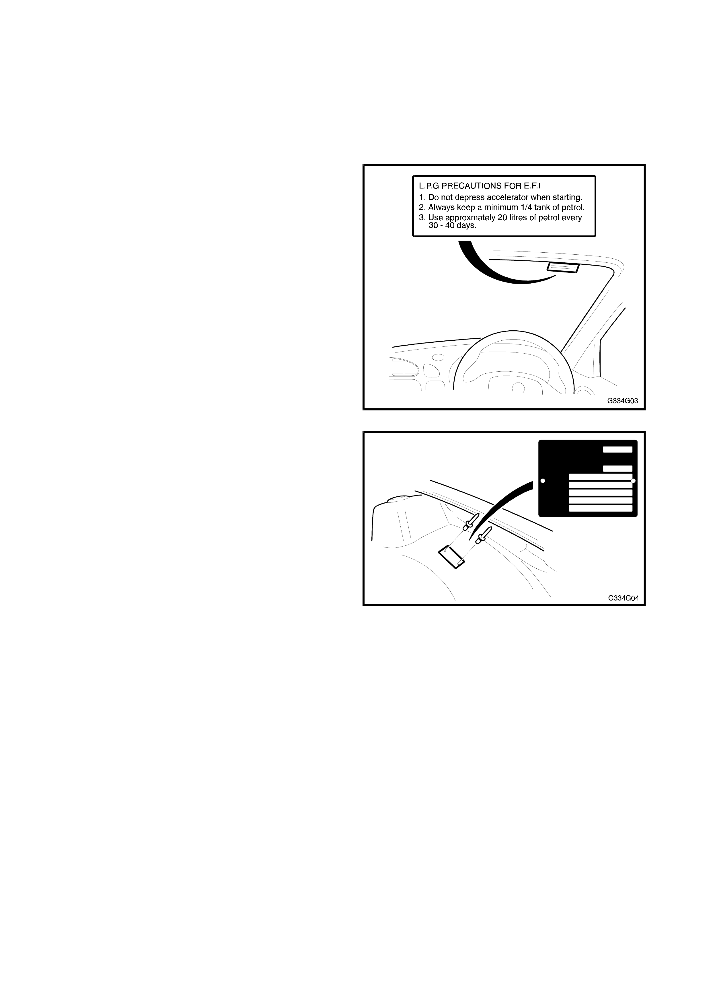
The LPG precaution label, fitted to the windscreen RH
upper as shown in Figure 4G-3, provides the driver
with information for operating the vehicle on LPG.
Figure 4G-3
A LPG compliance plate, if required by State
regulations, is riveted to the LH front wheelhouse
location.
Figure 4G-4

A filling information label is affixed to the inside of the
fuel filler cap.
NOTE: Where LPG is optioned, a revised petrol filler
cap is fitted which is lower in height. This allows
clearance between itself and the LPG filler.
Figure 4G-5
All VT series vehicles equipped with the Holden By
Design LPG system are fitted with a HBD
identification plate which is pop-riveted to the radiator
support panel.
Figure 4G-6