SECTION 4I - TELSTRA PACKAGES
CAUTION:
This vehicle will be equipped with a Supplemental Restraint System (SRS). A SRS will consist of
either seat belt pre-tension ers and a driver’s air bag , seat belt pre-t ensioners and a driv er’s and front
passenger’s air bag s or seat belt pre-tensio ners, driver’s and fron t passenger’s air bags and left and
right hand side air bags. Depending upon the system fitted, refer to SAFETY PRECAUTIONS, Section
12M Supplemental Restraint System in the VT Series I Service Information, before performing any
service operation on or around any SRS components, the steering mechanism or wiring. Failure to
follow the SAFETY PRECAUTIONS could result in SRS deployment, resulting in possible personal
injury or unnecessary SRS system repairs.
CAUTION:
This v ehicle may be equipped w ith LPG ( Liquefied Pet roleum Gas). In th e interests of safet y, the LPG
fuel system should be isolated by turning 'OFF' the manual service valve and then draining the LPG
service lines, before any service work is carried out on the vehicle. Refer to the LPG leaflet included
with the Owner's Handbook for details or in the VT Series I Service Information for more specific
servicing information.
1. GENERAL INFORMATION
This Section of the Holden By Design Service Infor mation Supplem ent describes the ser vice procedures f or the
packages fitted exclusively to Telstra vehicles:
• Headlights on system,
• Wagon shelving,
• Cargo barrier,
• Telstra decals, and
• Mudflaps.
The Telstra headlights on system interfaces with the vehicle’s lighting system and automatically turns the
headlamps on when the ignition is switched on.
Shelving is fitted to the rear com partment of station wagon m odels for the s torage of parts and tools. T wo types
can be fitted; short and long. Where long is installed, the rear seat is permanently folded forward.
Wagon models are also fitted with a cargo barrier, located in either the forward or rear position.
Depending on vehicle, several Telstra decals can be fitted. These can include the Telstra logo, Telstra name
and/ or a ‘Telstra values safe driving’ message.
Moulded mudflaps which are specifically designed for VT series vehicles may also be fitted.
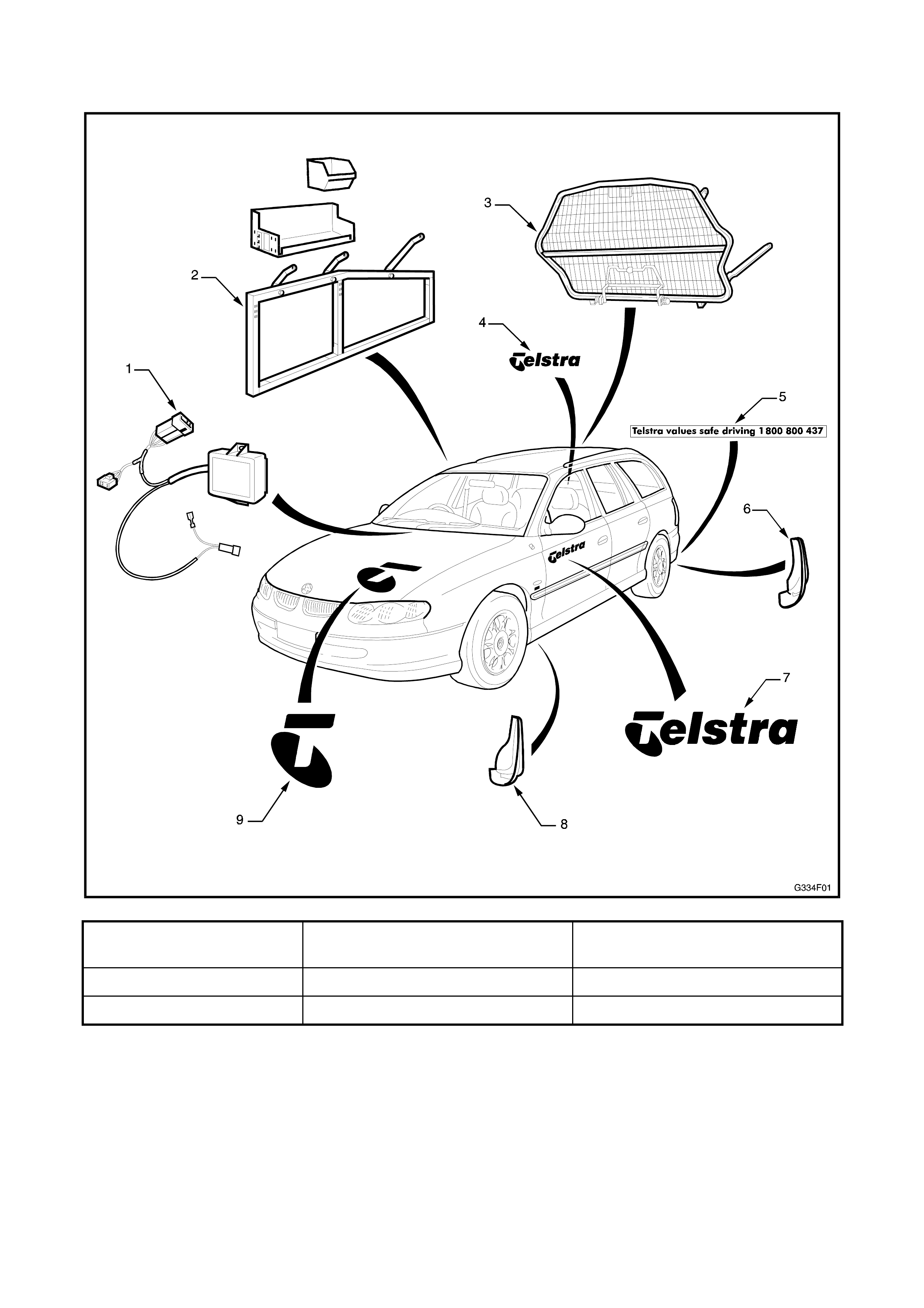
Fig. 4I-1 illustrates the major components fitted to Holden By Design Telstra vehicles.
1.1 MAJOR COMPONENTS
Figure 4I-1
1. Headlights on assembly 4. Telstra wordmark decal - tailgate 7. Telstra wordmark decal - front
door
2. Wagon shelving 5. Safe driving decal - rear bumper 8. Front mudflap
3. Wagon cargo barrier 6. Rear mudflap 9. Telstra logo decal - bonnet
2. HEADLIGHTS ON SYSTEM
The Holden By Design Telstra headlights on system
interfaces with the vehicle’s lighting system to provide
the functions detailed in the following table. Two
systems have been fitted. The early type, introduced
from October 1997 was revised to the late type mid
November 1997.
IGNITION
POSITION STALK POSITION HEADLAMP SWITCH POSITION
OFF PARK LIGHTS
Forward Low beam,
Tail/Park lamps
Early Type: Low
beam, Tail/Park
lamps
Late Type:
Tail/Park lamps
only
Main beam,
Tail/Park lamps
ON Centre Low beam,
Tail/Park lamps
Early Type: Low
beam, Tail/Park
lamps
Late Type:
Tail/Park lamps
only
Low beam,
Tail/Park lamps
Back Main beam,
Tail/Park lamps Main beam,
Tail/Park lamps Main beam,
Tail/Park lamps
Forward None Tail/Park lamps Main beam,
Tail/Park lamps
OFF Centre None Tail/Park lamps Low beam,
Tail/Park lamps
Back Main beam Main beam,
Tail/Park lamps Main beam,
Tail/Park lamps
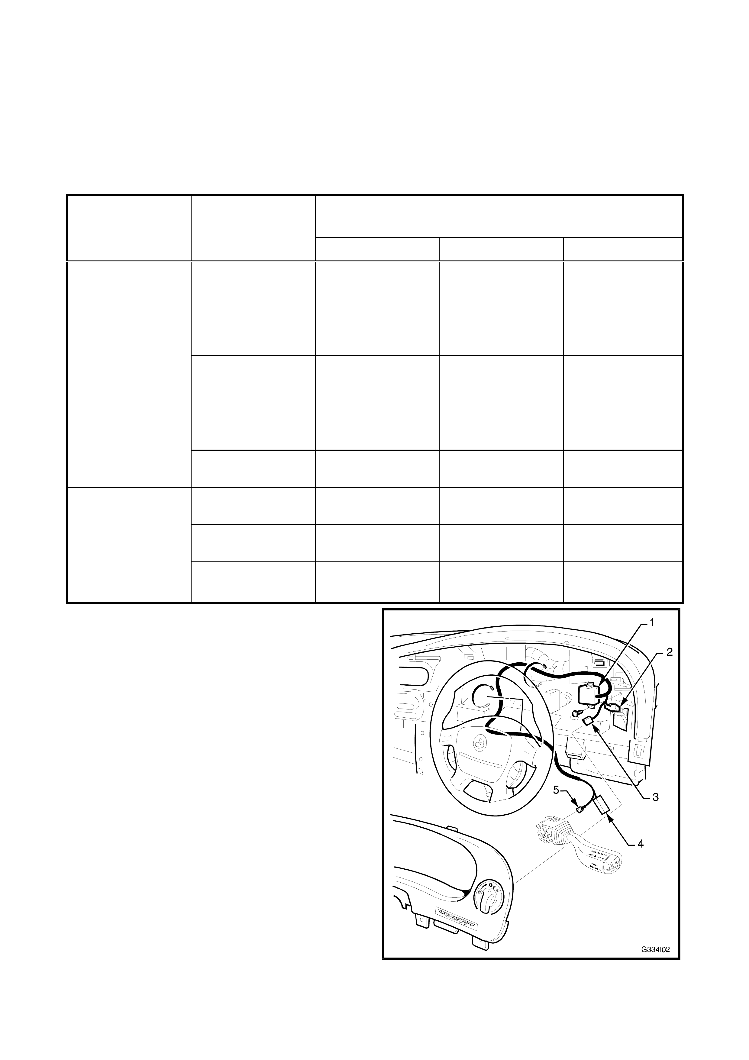
The headlights on system consists of an interface
module (1) which is mounted behind the instrument
cluster. It is connected between the headlamp switch
connector (2) and headlamp switch (3) and also the
indicator stalk white wires (4 & 5).
NOTE: Where the headlights on system is fitted to
Calais models, the Calais headlamp switch with auto
on function is replaced by a standard level headlamp
switch.
A ‘headlights on’ decal is affixed to the instrument
panel facia.
The front park lamp and tail lamp globes are also
replaced with long life globes. These are identified by
a pink filament insulator, the standard globe’s
insulator is white.
Figure 4I-2
REMOVE
1. Remove the instrument cluster as described in Section 12C, INSTRUMENTS, WIPERS/WASHERS &
HORN of the VT Series I Service Information.
2. Disconnect the headlights on wiring connectors (2 & 3) from the headlamp switch and wiring harness.
3. Remove the cable ties securing the headlights on wiring to the instrument wiring harness.
4. Remove the turn signal switch assembly as described in Section 12B, HEADLAMP & TURN SIGNAL
CONTROL SWITCH ASSEMBLY in the VT Series I Service Information.
5. Disconnect the headlights on wiring connectors (4 & 5) from the turn signal switch and wiring harness.
6. Remove the screw securing the headlights on module.
7. Remove the module and wiring.
INSTALL
1. Installation is the reverse of removal.
NOTE: Ensure the wiring is correctly routed and the cable ties that were removed are replaced.
FAULT FINDING
1. Restore the system to standard:
Remove the headlights on wiring patch connectors from the headlight switch and harness and connect the
lighting system harness directly to the switch.
Remove the white wire from the patch wiring connector near the turn signal switch. Remove the patch
harness white wire from the turn signal switch connector. Place the lighting system white wire directly into
the connector cavity.
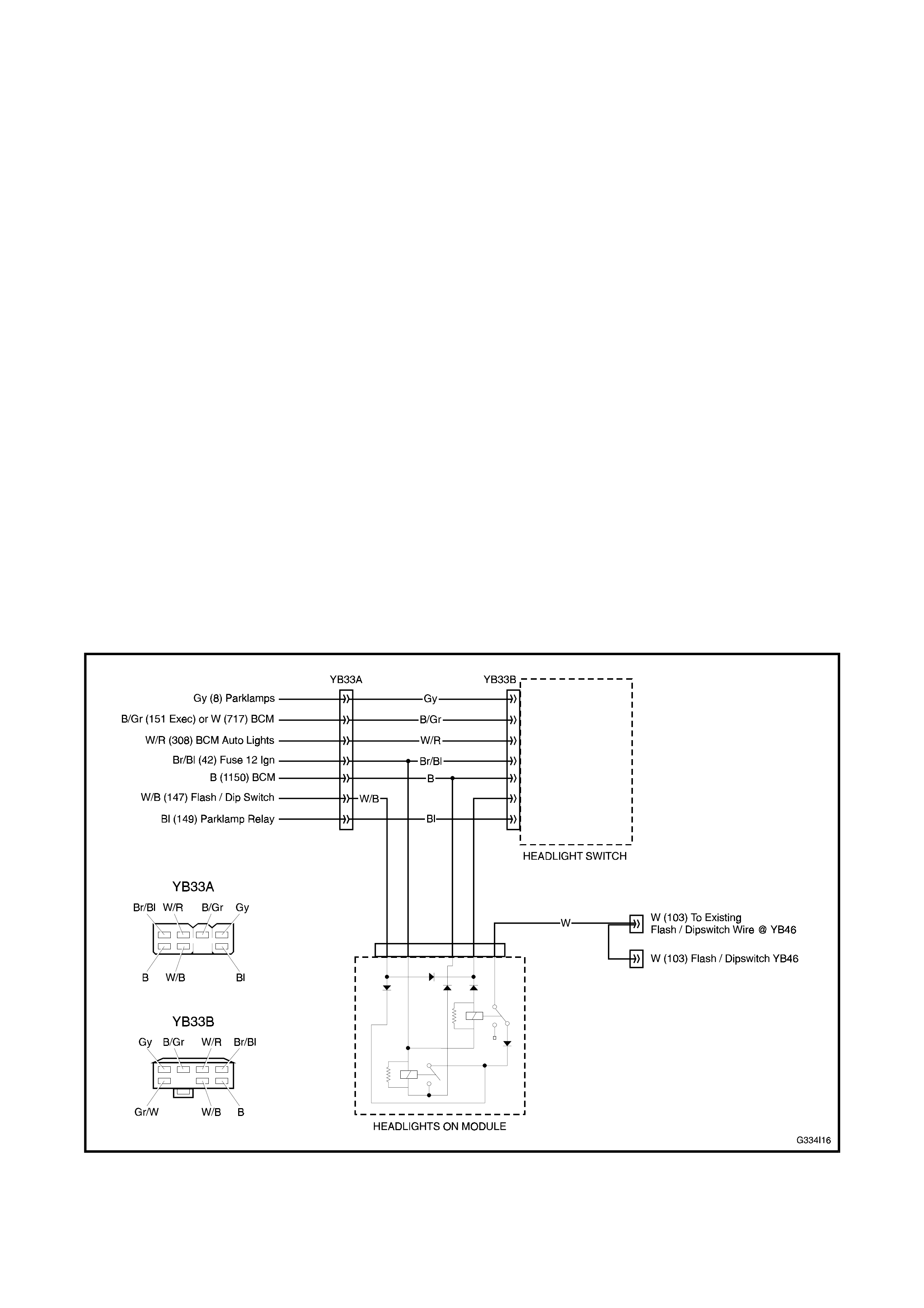
2. Check that the headlamp system operates correctly. If so, repair or replace the headlights on module
assembly as required by using the headlights on wiring schematic in Fig. 4I-3 early type or Fig. 4I-4 late
type in conjunction with the appropriate wiring diagram in Section 12P, WIRING DIAGRAMS in the VT
Series I Service Information.
If not, test for a fault in the lighting system. Refer to Section 12B, LIGHTING SYSTEM in the VT Series I
Service Information.
Figure 4I-3
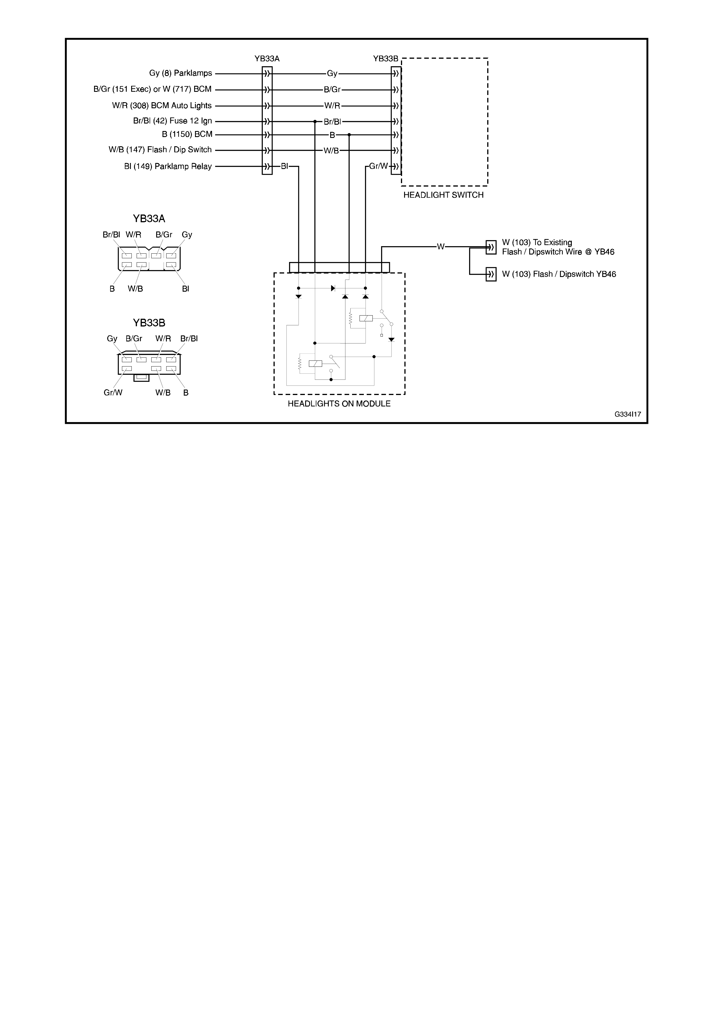
Figure 4I-4

3. WAGON SHELVING
The Holden By Design Telstra wagon shelving
provides stor age space f or s pare par ts and tools. T he
shelving consists of a square section steel frame
mounted to the vehicle’s inner side panel upper and
rear floor.
Two shelving types are available; long and short. Both
are fitted in the same way except the number and
positions of the mounting bolts.
Shelf units are clipped into each frame. Several
diff erent shelf units ar e available and are identified by
a code printed on a label affixed to the underside of
each shelf unit. Storage boxes are then placed in
each shelf.
To allow access to the spare wheel, the rear f loor trim
is cut allowing clearance between the shelf units when
raised.
REMOVE
1. Remove the storage boxes (1) from the shelf
units (2).
2. Remove the shelf units from the frame (3).
NOTE: Record the position of each shelf and its slot
number prior to removal.
3. Remove from two places, the bolts (4), and from
underneath the vehicle, the plate (5) and nut (6).
4. Remove the lock nut (7), nut (8) and spacer (9)
from the centre upper mount (long shelf only).
The bolt (10) is a cargo barrier mount, described
in 4. CARGO BARRIER in this Section, which
attaches to the bracket and bolt assembly (11).
5. Remove the remaining upper mount bolts (12)
and carefully lift out the frame.
6. If required, the upper m ount plate ass em blies can
be removed by loosening the two screws per
mount (13). Using a length of wire, bend it to
shape to hook it onto the bolt plate (14) through
the centre hole. Remove the screws and trim
plate (15) and carefully remove the bolt plate
through the large centre hole.
NOTE: Do not allow the bolt plate to drop into the
cavity.
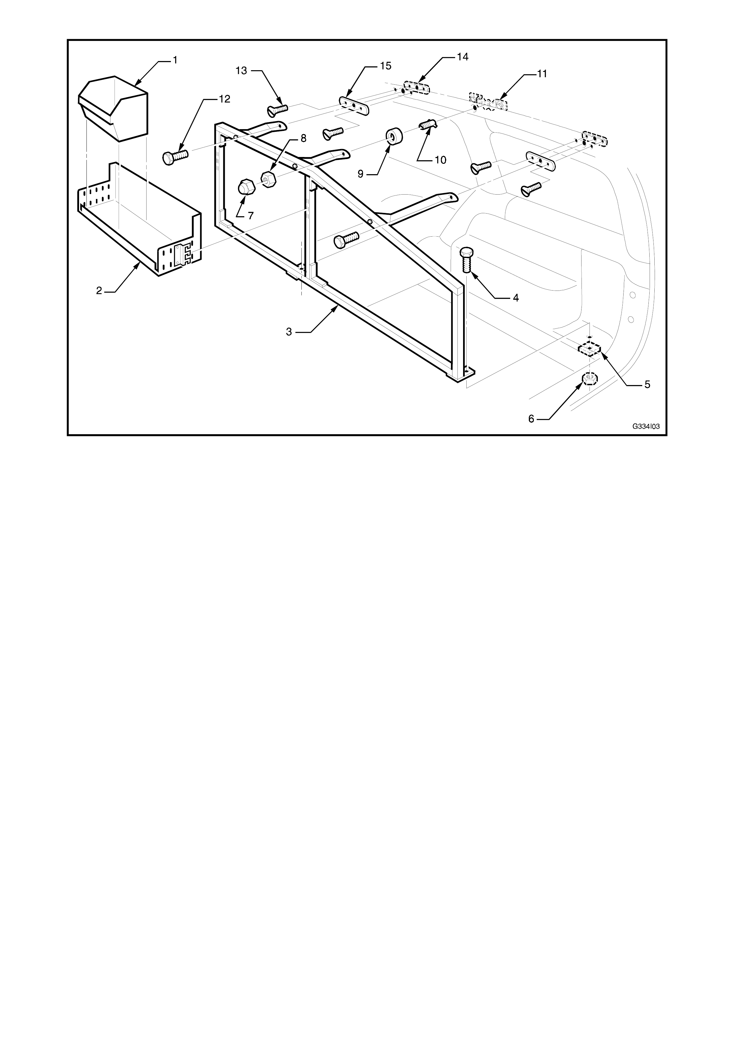
Figure 4I-5
INSTALL
1. If the upper mount plates were not removed,
proceed to Step 8.
2. Using the dimensions shown in Fig. 4I-6 long
shelf or Fig. 4I-7 short shelf, mark the upper
mount holes. Measure from the top edge of the
plastic side tr im upper ( 1) and from the join of the
upper side trims (2).
NOTE: The centre upper mount for the long shelf
uses the standard cargo barrier mount. Do not drill
this hole. Simply locate it and punch a hole through
the headlining into the centre of the bracket and bolt
assembly. For further inform ation refer to Section 4F,
VT Series COUNTRY DRIVING & LOAD
MANAGEMENT in this Supplement.
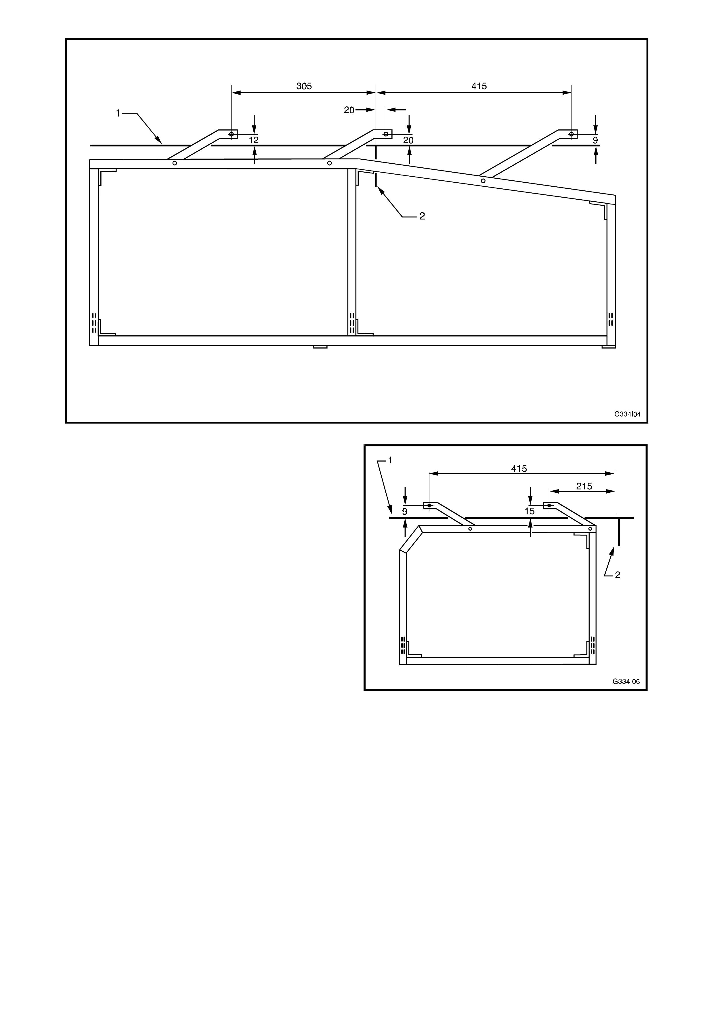
Figure 4I-6
Figure 4I-7

3. For the front & rear upper mount centre holes, drill a pilot hole through the headlining into the upper side
panel. Drill this out to 22 mm with a hole saw.
4. Using a bolt plate (14) in Fig. 4I-5, mark the two bolt plate mounting screw holes. Drill the holes with a 8 mm
drill bit.
5. Using a length of wire hooked ar ound the bolt plate c entre hole, c ar ef ully insert the bolt plate thr ough the 22
mm hole and position it to align the screw holes.
6. Thread the plastic trim plate onto the wire and align the holes.
7. Install the screws loosely, unhook the wire and tighten the screws.
8. Fit the shelf frame into position and loosely install the upper bolts.
9. Align the frame with the lower bolt holes, or if the rear floorpan was replaced, drill the holes through the
floorpan and prime any bare metal.
10. Assemble the lower mount bolt (4), plate (5) and nut (6) in Fig. 4I-5, and tighten.
11. F or the long shelf, ins ert the centre upper m ount stud into the cargo barr ier brac ket and bolt assem bly and
fit the nut. Turn the stud 90 degrees while holding it with a screwdriver and tighten. Fit the locknut and
tighten.
12. Tighten the remaining upper mount bolts.
13. Fit the shelf units and storage boxes.
4. CARGO BARRIER
The Holden By Design Telstra cargo barrier is the
same cargo barrier described in Section 4F, VT
SERIES COUNTRY DRIVING & LOAD
MANAGEMENT in this Supplement with the
exception of the upper mount.
The Telstra wagon cargo barrier is a semi-permanent
fixture. It can be located in the front or rear positions,
depending on the configuration of the vehicle.
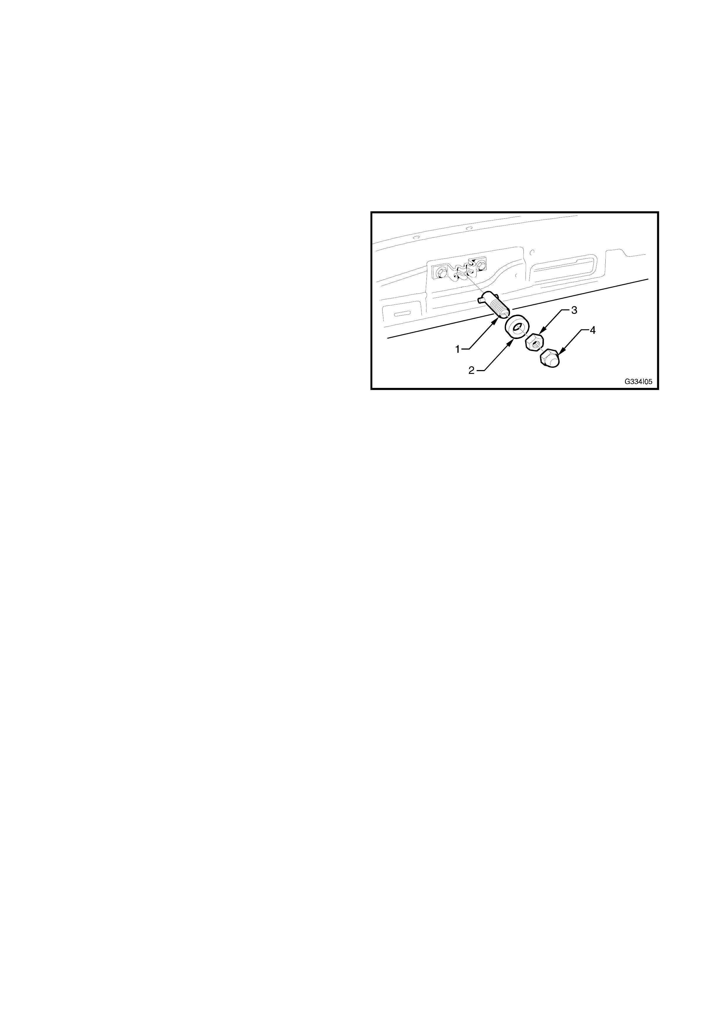
Where the standard Holden By Design wagon cargo
barrier has a quick release knob for the top mount, a
threaded T-piece (1), spacer (2), nut (3) and domed
locknut (4) are used for the top mount on Telstra
vehicles.
The threaded T-piece locates into the upper bracket
and bolt assembly, which is fitted as standard to all
VT Series wagons.
Figure 4I-8
For all other servicing procedures for the Holden By
Design Telstra cargo barrier, refer to Section 4F, VT
Series COUNTRY DRIVING & LOAD
MANAGEMENT in this Supplement.

5. TELSTRA DECALS
Holden By Design af fix the decals identifying T elstra vehicles. T he proc edure f or af fixing the decals is the s ame
for all types, only their position and size differs.
REMOVE
1. Heat on the corner of the decal with a heat gun, heat lamp or hot water.
2. Insert a razor blade or knife edge under the corner to loosen the decal from the surface.
3. Pull the decal back slowly at an angle of less than 90° while continuing to apply heat to the dec al j us t ahead
of the area that is being removed.
NOTE: Where paintwork adhesion may be weak, slow pulling action is required.
4. If adhesive r esidue remains after rem oval of the decal, the adhesive may be rem oved by wiping with a rag
saturated with a solvent such as methylated spirits and then scraping with a plastic applicator.
NOTE: Care must be exercised with this procedure as damage to the paintwork may result.
APPLY
NOTE: These instructions are for the application of 3M brand Control Tac vinyl decals. The water and detergent
method, should not be employed for these decals.
1. Clean the surface where the decal is to be applied with an appropriate wax and grease remover.
2. Air and surface temperatures must be above 10°C.
3. Place a length of masking tape or like on the surface where the edge of the decal is to align. Refer this
section for the relevant decal placement.
4. Carefully apply the decal to the surface in a dry state.
NOTE: The decal can be repositioned until burnished with an applicator, however careful placement in the first
instance will minimise the risk of misalignment and/or damage to the decal.
5. Using overlapping strokes, burnish the decal onto the surface with a rubber squeegee or plastic applicator.
NOTE: Apply firm pressure.
6. Remove the cover sheet at an angle of 180°.
7. Re-burnish all edges and overlaps.
8. Puncture any remaining air bubbles with a pin or round pointed tool and smooth down the decal.
NOTE: Do not use a razor blade or knife.
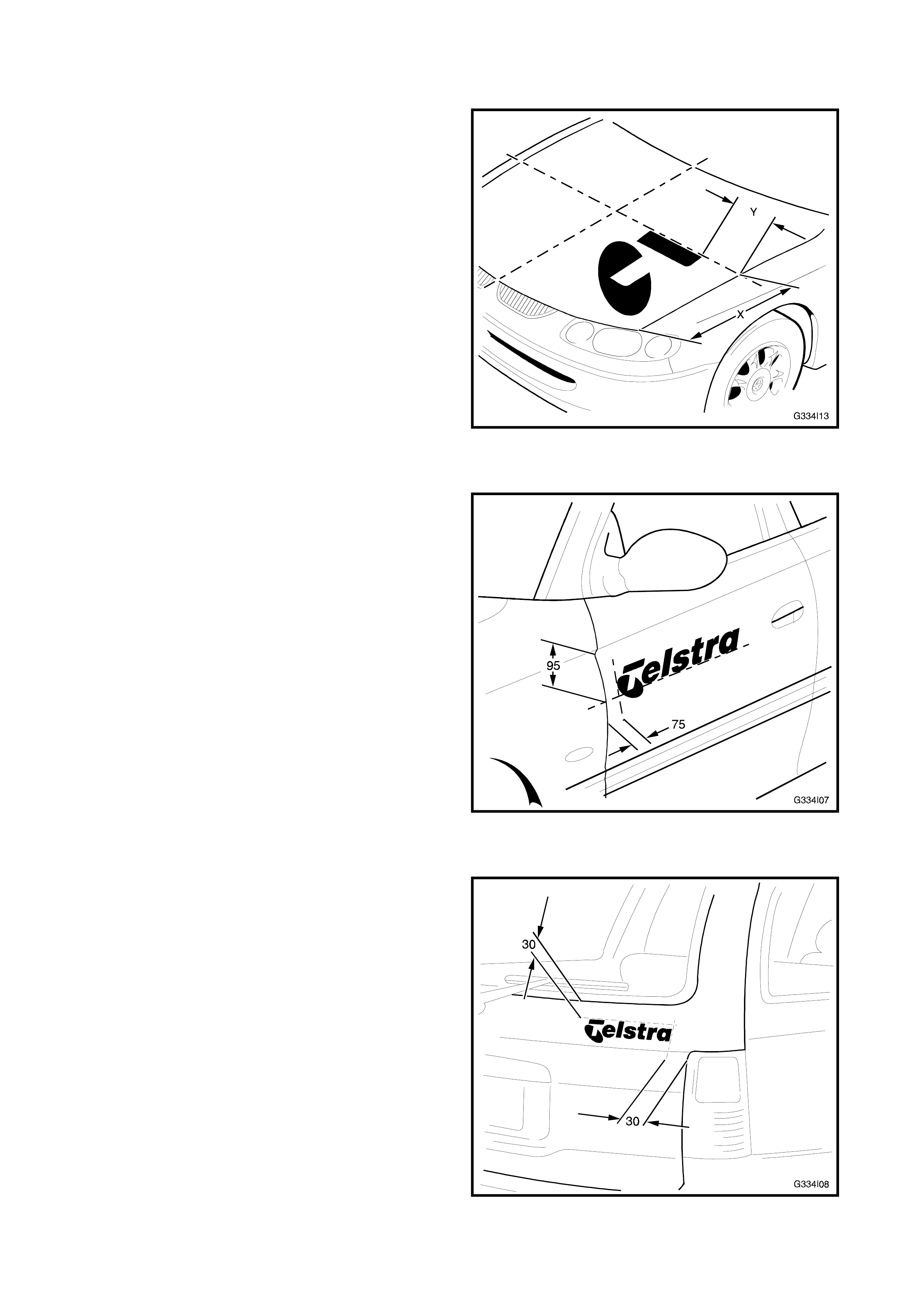
BONNET DECAL
The ‘T ’ s ymbol is placed on the LH s ide of the bonnet,
towards the front of the vehicle. The cross bar of the
‘T’ is to be perpendicular to the centre line.
As shown (X), measure back evenly from both
corners of the bonnet and apply mask ing tape ac ross
the bonnet to provide a reference to align the decal.
Measure in from the side (Y) the required distance
and apply the decal as previously described.
Decals are similarly located on VS Series vehicles.
NOTE: Dimension X is approximately 500 mm and Y
is approximately 150-200 mm, however these
dimens ions do vary, check the original location on the
vehicle.
Figure 4I-9
FRONT DOOR DECAL
The Telstra wordmark is placed on the both front
doors as shown for VT Series vehicles.
The baseline is to be parallel to the ground (with the
vehicle at its normal load). Do not follow body
mouldings or style lines.
For VS Series vehicles, centre the base line in the
upper section of the door.
Apply mas king tape to provide a r ef er ence to align the
decal.
Measure in from the front edge the required distance
and apply the decal as previously described.
Figure 4I-10
WAGON TAILGATE DECAL
A sm all Tels tra wordmar k is plac ed on the RH s ide of
the wagon tailgate, as shown for VT Series vehicles,
and similar for VS Series.
The baseline is to be parallel to the ground - do not
follow body mouldings or sty le lines.
Apply mas king tape to provide a r ef er ence to align the
decal.
Measure in from the side the required distance and
apply the decal as previously described.
Figure 4I-11
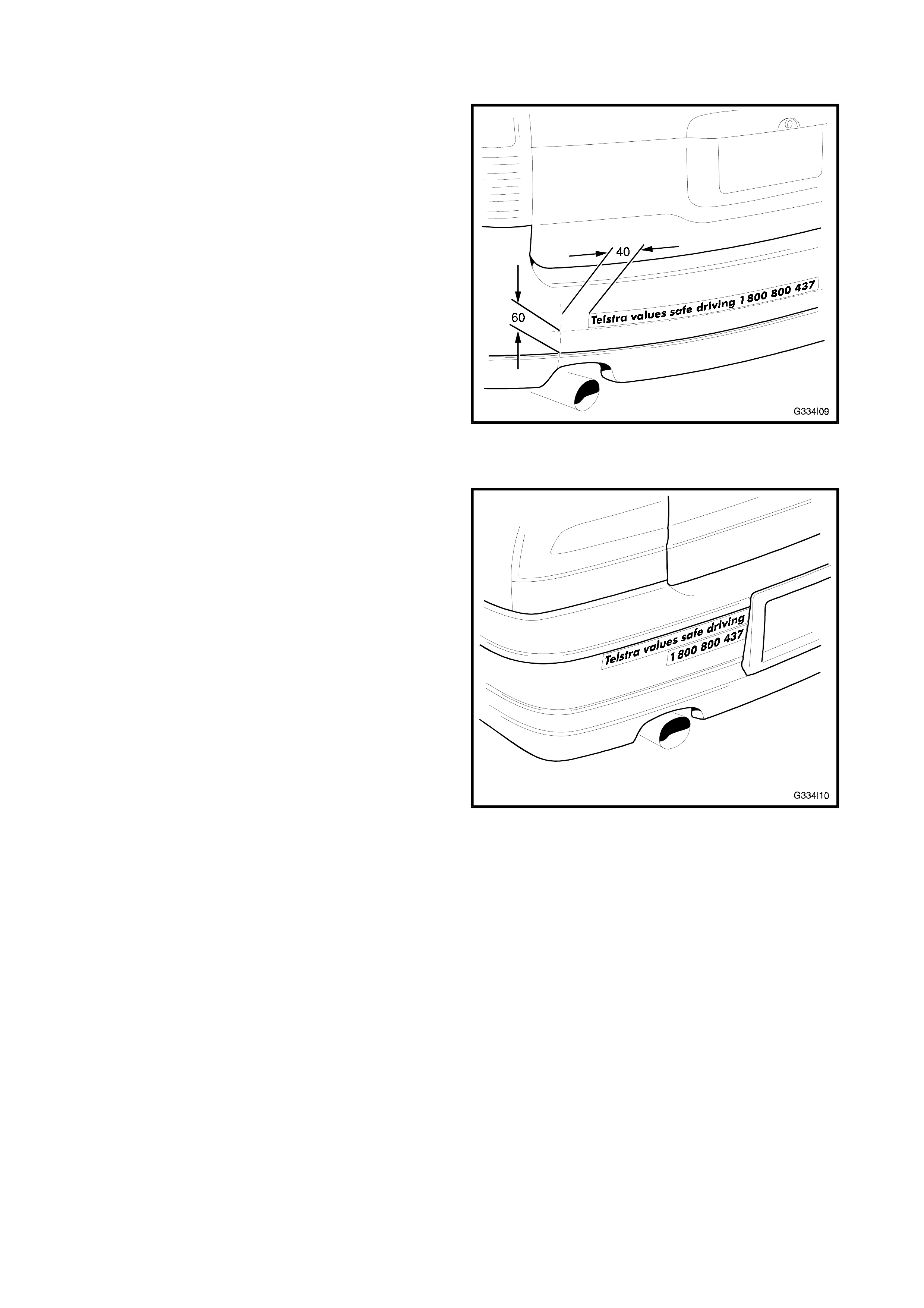
REAR BUMPER DECAL - EXCEPT VS LWB
The ‘Telstra values safe driving’ decal is placed on
the LH side of the rear bumper as shown for VT
Series vehicles. For VS Series, except LW B models,
meas ure in from the join of the centre to side bum per
sections and place it central on the vertical plane.
Apply mas king tape to provide a r ef er ence to align the
decal and apply the decal as previously described.
Figure 4I-12
REAR BUMPER DECAL - VS LWB
The ‘Telstra values safe driving’ decal is placed on
the LH side of the rear bumper as shown for VS
Statesman and Caprice models. Cut the decal
between the word ‘driving’ and the phone number,
prior to removing the backing.
Apply the decal as previously described, aligning the
top edge of the first section slightly below the lower
edge of the moulding strip. The RH end of the decal
aligns near the number plate surround.
Place the second section underneath, also aligning
the RH end near the number plate surround.
Figure 4I-13
6. MUDFLAPS
VT Series Telstra vehicles are fitted with Holden By
Design moulded mudflaps.
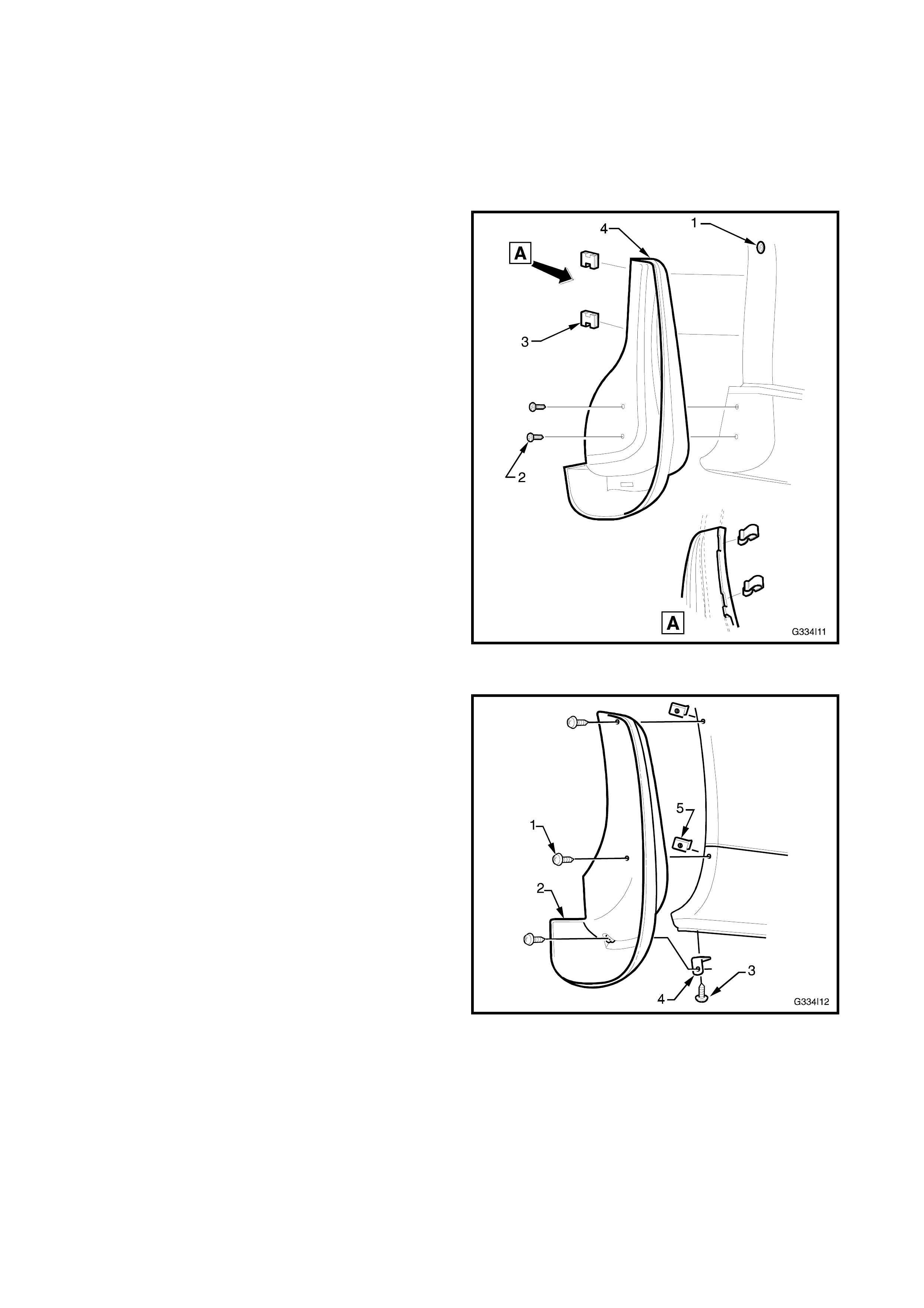
REMOVE
Front
1. Raise the front of the vehicle and place on safety
stands. Refer to Section 0A GENERAL
INFORMATION in the VT Series I Service
Information.
2. Remove the front wheel cover (steel wheels) or
centre cap (alloy wheels).
3. Mark the relationship of each wheel to hub/brake
disc. Remove the road wheel attaching nuts and
remove the wheel.
4. Remove the fender liner screw (1).
5. Remove the two mudflap attaching screws (2).
6. Remove the two mudflap attaching clips (3) and
remove the mudflap (4).
Figure 4I-14
Rear
1. Raise the rear of the vehicle and place on safety
stands. Refer to Section 0A GENERAL
INFORMATION in the VT Series I Service
Information.
2. Remove the rear wheel cover (steel wheels) or
centre cap (alloy wheels).
3. Mark the relationship of each wheel to hub/brake
disc. Remove the road wheel attaching nuts and
remove the wheel.
4. Remove the three screws (1) attaching the
mudflap (2) to the rear bumper facia and remove
the mudflap.
5. If required, remove the screw (3) attaching the
mudflap lower mounting bracket (4) to the
bumper facia.
6. For wagon models, remove the U-nut (5) from
two places. Figure 4I-15

INSTALL
Front
1. Fit the mudflap in position and install the two lower
screws (2) as shown in Fig. 4I-14, ensuring a neat
fit of the mudflap against the fender and rocker
panel extension.
2. Install the two clips attaching the mudflap to the
fender ensuring the clips are seated in their
notches.
3. Install the fender liner screw (1) in Fig. 4I-14.
4. Install the wheel, aligning the marks made on
removal. Tighten the wheel attaching nuts to the
correct torque specification.
ROAD WHEEL ATTACHING NUT 110-140 Nm
5. Lower the vehicle to the ground.
Rear
1. Fit the lower mounting bracket (4) in Fig. 4I-15.
2. Fit the mudflap into position and install the lower
screw into the lower mounting bracket.
3. For wagon models, drill the two upper screw holes
with a 5mm drill if required and install the U-nuts
(5) in Fig.4I-15.
4. Fit the two upper screws, ensure a neat fit of the
mudflap against the bumper facia and tighten the
screws.
5. Install the wheel, aligning the marks made on
removal. Tighten the wheel attaching nuts to the
correct torque specification.
ROAD WHEEL ATTACHING NUT 110-140 Nm
6. Lower the vehicle to the ground.