
SECTION 4J - VT & WH SERIES HAND CONTROL
SYSTEM
CAUTION:
This vehicle will be equipped with a Supplemental Restraint System (SRS). A SRS will consist of
either seat belt pre-tension ers and a driver’s air bag , seat belt pre-t ensioners and a driv er’s and front
passenger’s air bag s or seat belt pre-tensio ners, driver’s and fron t passenger’s air bags and left and
right hand side air bags. Depending upon the system fitted, refer to SAFETY PRECAUTIONS, Section
12M Supplemental Restraint System in the VT Series I Service Information, before performing any
service operation on or around any SRS components, the steering mechanism or wiring. Failure to
follow the SAFETY PRECAUTIONS could result in SRS deployment, resulting in possible personal
injury or unnecessary SRS system repairs.
1. GENERAL INFORMATION
This Section of the Holden By Design Service Information Supplement, describes the m aintenance and service
procedures for the Hand Control System available with VT & WH Series vehicles.
Designed and only provided for driver s with special needs , the hand c ontrol s ystem allows brake and acc eler ator
control from a steering column mounted lever, which is operated with the right hand. A steering wheel ‘spinner’
knob and indicator stalk extension allow complete turning of the steering wheel and indicator operation with the
left hand.
The hand control system is available only with automatic transmission vehicles and meets AS 3954, motor
vehicle controls, adaptive systems for people with disabilities.
Most Austr alian States require the driver of a vehicle f itted with a hand control system hold a spec ially endorsed
licence.
NOTE: It is a mandatory requirem ent by licencing authorities f or the steer ing wheel knob to be f itted for dis abled
drivers.
The hand control assembly restricts access to the fuse panel. Section 3.1 provides a simple procedure for
accessing the fuses should servicing be required.
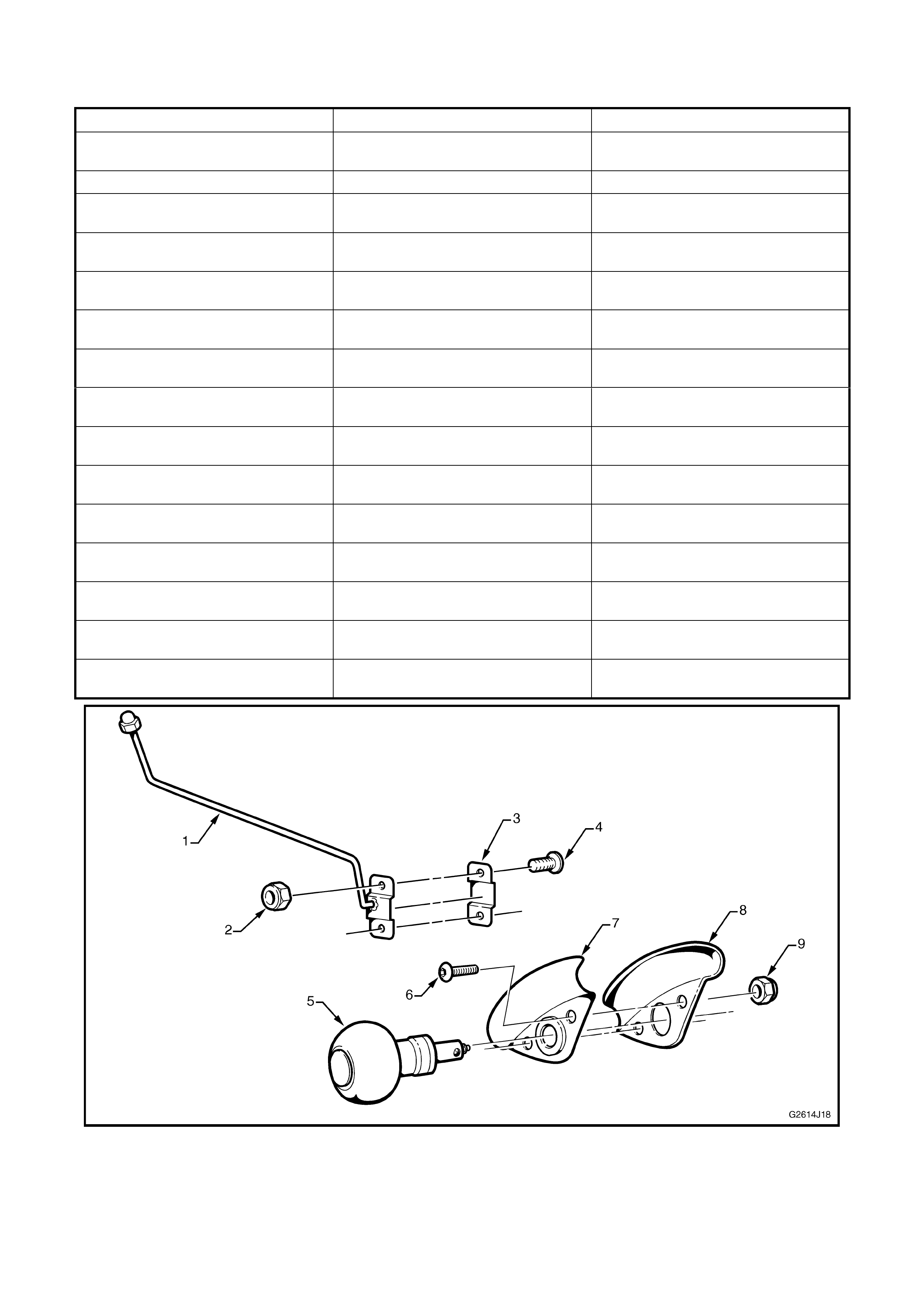
1.1 COMPONENTS
1. Indicator extension arm 17. Hand control assembly 33. Brake pedal clamp, part B
2. Nut – indicator arm mounting (x 2) 18. Pin – lever mounting 34. Spring washer – brake pedal
clamp (x 2)
3. Bracket – indicator arm mounting 19. Screw – lever mounting M8 (x 2) 35. Nut – brake pedal clamp (x 2)
4. Screw – indicator arm mounting
(x 2) 20. Lever assembly 36. Nut – accelerator rod joint, hand
control assembly end
5. Knob – steering wheel spinner 21. Bolt – lever to brake pedal rod
joint M8 37. Spacer – accelerator rod joint,
hand control assembly end
6. Screw – steering wheel knob
mounting (x 2) 22. Spring washer – lever to brake
pedal rod joint 38. Spring washer – accelerator rod
joint, hand control assembly end
7. Bracket, front – steering wheel
knob mounting 23. Nut – lever to brake pedal rod
joint 39. Rose joint – accelerator rod, hand
control assembly end
8. Bracket, rear – steering wheel
knob mounting 24. Rose joint – brake pedal rod,
lever end 40. Rod – accelerator pedal, 100 mm
9. Nut – steering wheel knob
mounting (x 2) 25. Locknut – brake pedal rod upper 41. Rod – accelerator pedal, 50 mm
10. Bolt – steering column mounting
M8 x 35 mm HT (x 2) 26. Rod – brake pedal 42. Rod – accelerator pedal, pedal
end
11. Washer – shake proof, steering
column mounting (x 2) 27. Locknut – brake pedal rod lower
(x 2) 43. Adjusting rod – accelerator pedal
rod
12. Flat washer – steering column
mounting (x 2) 28. Rose joint – brake pedal rod,
pedal end 44. Locknut – accelerator pedal rod
lower (x 3)
13. Mounting bracket 29. Spring washer – rose joint to
brake pedal clamp 45. Rose joint – accelerator pedal,
pedal end
14. Bolt – mounting bracket to hand
control assembly M8 HT (x 2) 30. Nut – rose joint to brake pedal
clamp 46. Spring washer – accelerator pedal
rod, pedal end
15. Spring washer – mounting
bracket to hand control ass’y (x 2) 31. Bolt – brake pedal clamp M8 (x 2) 47. Clamp – accelerator pedal
16. Steering column adjustment lever
stop plate 32. Brake pedal clamp, part A 48. Grub screw – accelerator pedal
clamp (x2)
Figure 4J-1
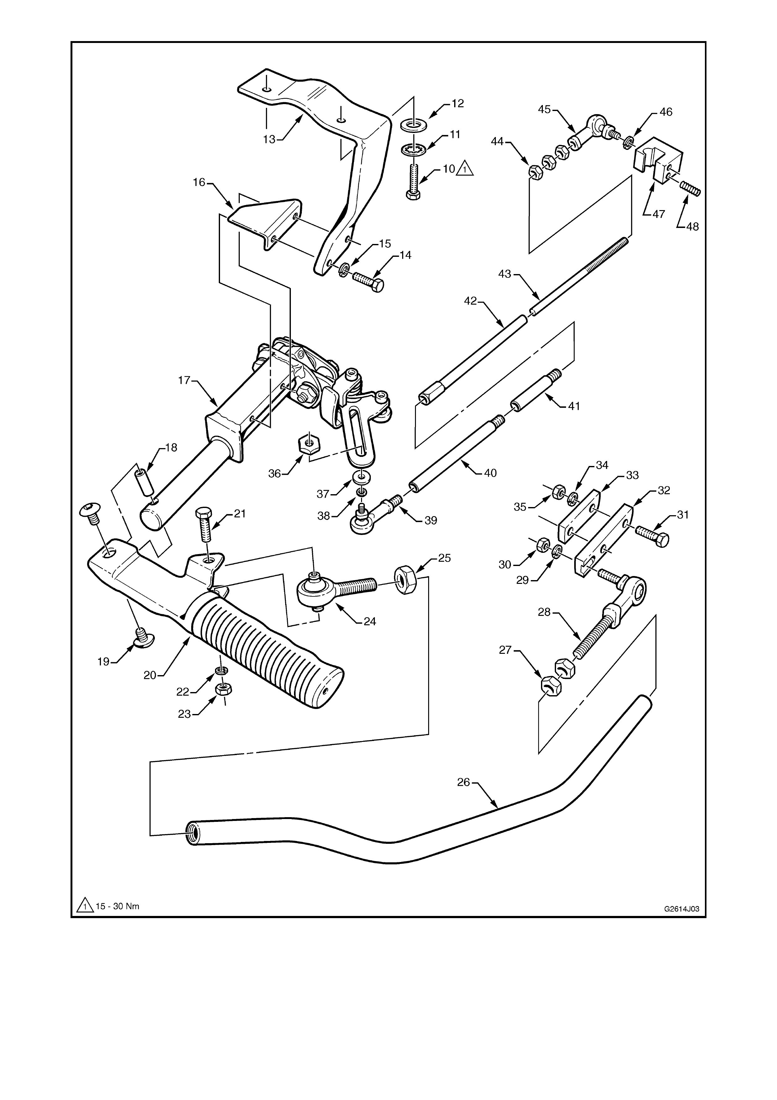
Figure 4J-2
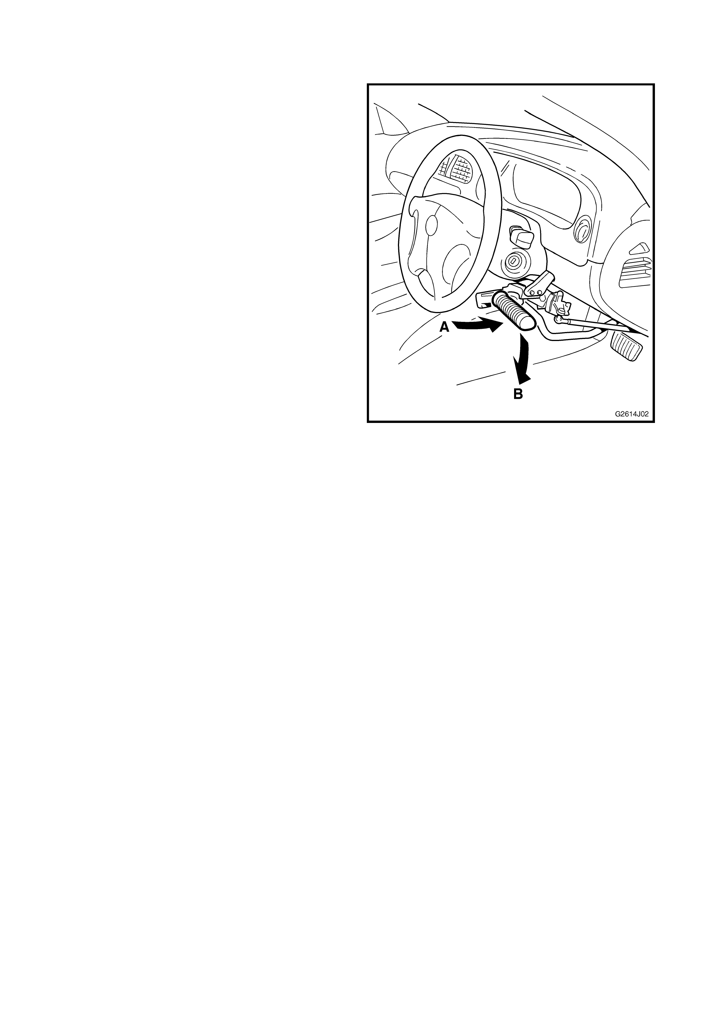
1.2 OPERATION
While operation of the hand control system is
relatively straightforward, familiarisation is required.
Brake application is achieved by pushing the lever
away from you, toward the dash (A). Pushing the
lever downward (B) toward your lap operates the
accelerator.
NOTE: It is recommended that non-authorised
persons do not drive a vehicle fitted with the hand
control system. However, circumstances may
necessitate service personnel drive such a vehicle.
Follow the procedures below and practice
maneuvering the vehicle in an isolated area before
driving the vehicle.
1. Start the engine.
2. W ith the engine at idle, depress the lever to apply
the brakes. Rev the engine slightly several times
to get the feel of the accelerator by pushing the
lever downwards.
3. Release the parking brake and place the
transmission selector in drive (or reverse if
required).
4. Release the brake lever while applying the
accelerator slightly.
5. Reapply the brake to get the feel of the braking
effort required.
6. Repeat as required until you feel confident of the
controls.
Figure 4J-3

2. MAINTENANCE
The Hand Control System has been designed for years of trouble free motoring, providing it is serviced and
inspected every twelve months in accordance with the following table.
ITEM
NO. COMPONENT ACTION SPECIFICATION
1. Hand grip Check for wear and fit Replace as required
2. Idle Speed If incorrect, throttle body return
spring may have lost tension.
Perform Tech II diagnostic
checks.
If OK, replace spring as required.
V6 – 725 ± 50 Auto in
N775 ± 50 Man
5.0 V8 – 700 ± 100 All
GEN III V8 – 650 ± 50
Auto in N 800 ± 50 Man
3. Mounting Bolts Check for looseness Tighten securely as required
4. Pedal Clamps Check for looseness Tighten securely and check
position as required
5. Pivots Check for looseness and/or wear Tighten securely as required
or replace if excessive play
6. Rose joints Check for wear Replace if excessive play
7. Brake pedal linkage Free-play
Position
Operation
Adjust if not approx. 2 mm
Adjust if too high or low
Check for binding, stiffness
8. Accelerator pedal linkage Free-play
Position
Operation
Adjust if not approx. 2 mm
Adjust if too high or low
Check for binding, stiffness
9. Spinner knob Check for looseness
Ensure knob spins freely Tighten securely as required
10. Indicator stalk extension Check for looseness
Ensure correctly positioned Tighten securely as required
Bend as required
11. All components Check for wear or damage Replace as required
3. SERVICE OPERATIONS
The Holden By Design Hand Control System mounts
below the steering column and attaches to the brake
and accelerator pedals. The fuse panel cover is
modified to fit around the steering column mounting
bracket.
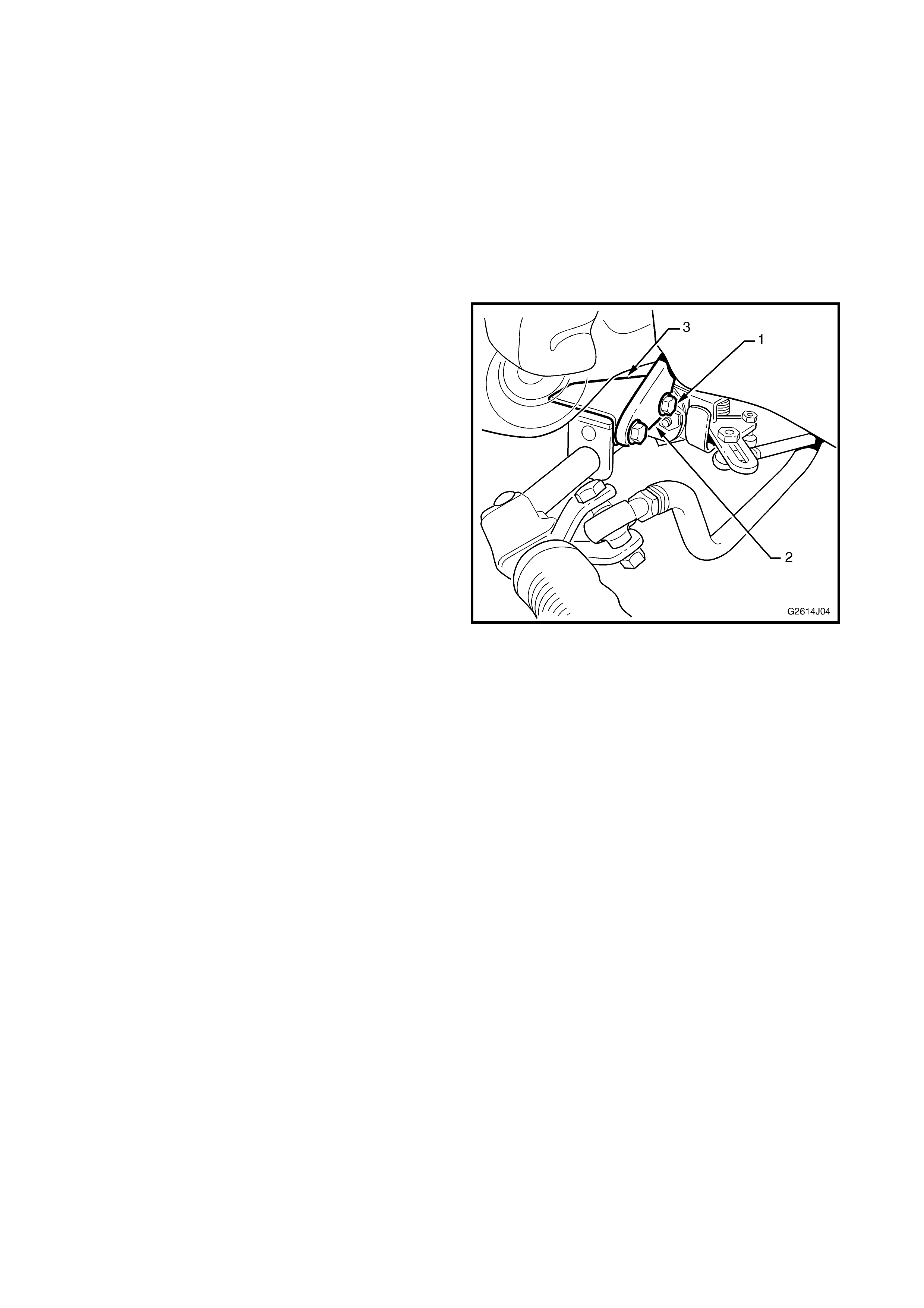
3.1 FUSE PANEL ACCESS
The hand control assembly restricts access to the
fuse panel. The following procedure provides the
simplest means for accessing the fuses.
1. Remove the two bolts (1) attaching the hand
control assembly to mounting bracket (2).
2. Lower the hand control assembly to the floor.
NOTE: Steering column adjustment lever stop plate
(3) is also removed with the assembly.
3. Open the fuse panel cover by grasping each top
corner and pulling down. Service the fuses as
required.
4. Close fuse panel cover.
5. Return the steering column adjustment to its
correct position, if it has been moved.
6. Raise the hand control assembly into position at
the mounting bracket and fit the steering column
lever stop plate.
7. Insert bolts and tighten securely.
8. Check correct operation. Figure 4J-4
3.2 HAND CONTROL ASSEMBLY
REMOVE
1. Disconnect battery to disable the SRS air bag
system.
NOTE: Disconnecting the batter y will render the radio
inoperative until the correct security PIN code is
entered. Refer to the audio system operating
instructions provided with the vehicle owner’s
handbook for further information.
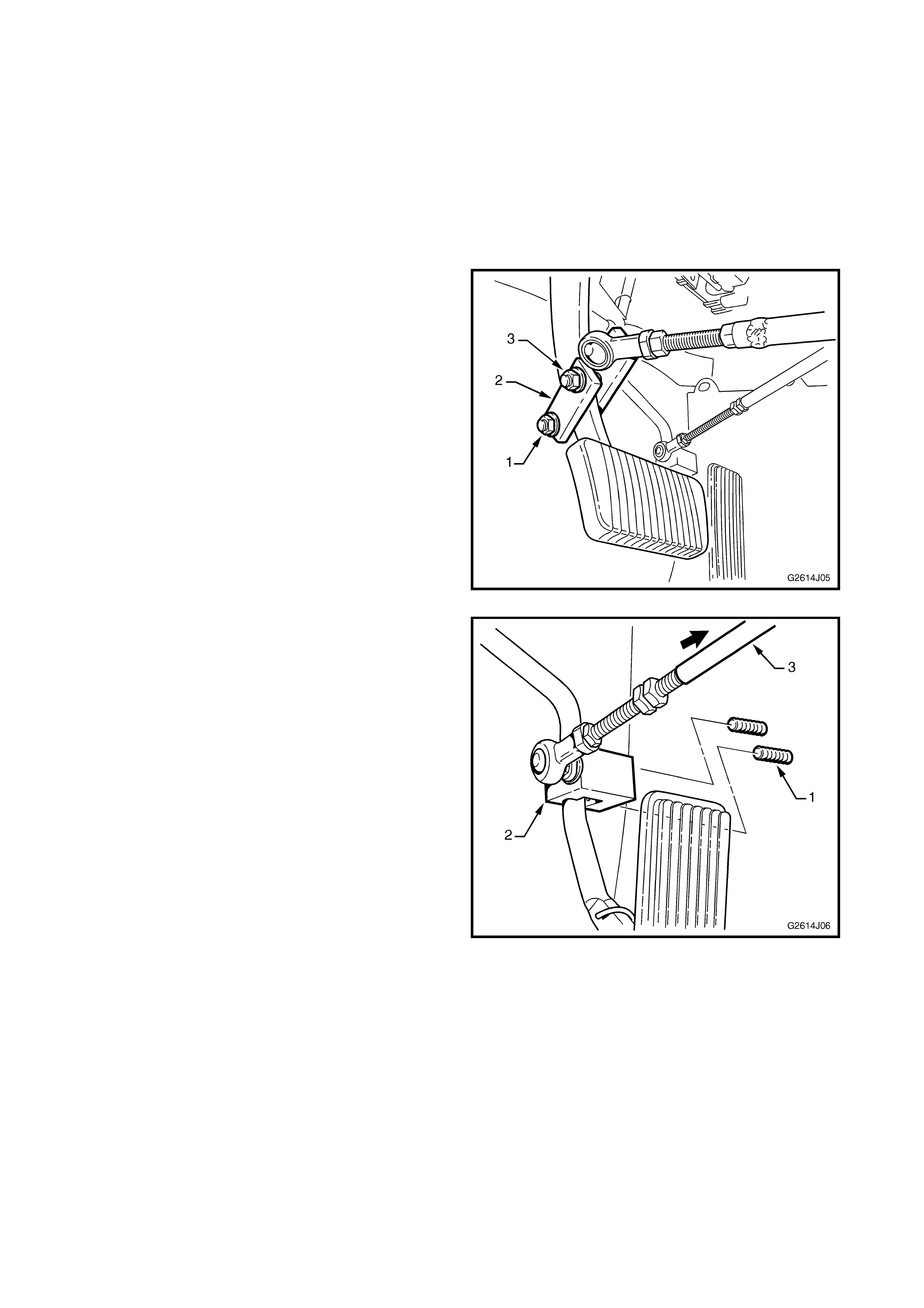
2. Slightly loosen the nut and bolt (1) fr om the brak e
pedal clamp (2).
3. Completely remove the other nut and bolt (3).
4. Remove the clamp from the pedal and rest
linkage on the floor.
Figure 4J-5
5. Either:
• Loosen the two grub screws (1) from the
accelerator clamp (2).
Remove the clamp from the pedal and rest
the linkage on the floor, or
• Once the hand control assembly is lowered,
slide the linkage shaft (3) off the end link.
Figure 4J-6
6. Remove the two bolts (1) attaching hand control
assembly to mounting bracket (2).
NOTE: Steering column lever stop plate (3) is also
removed with the assembly.
7. Remove hand control assembly from vehicle.
Figure 4J-7
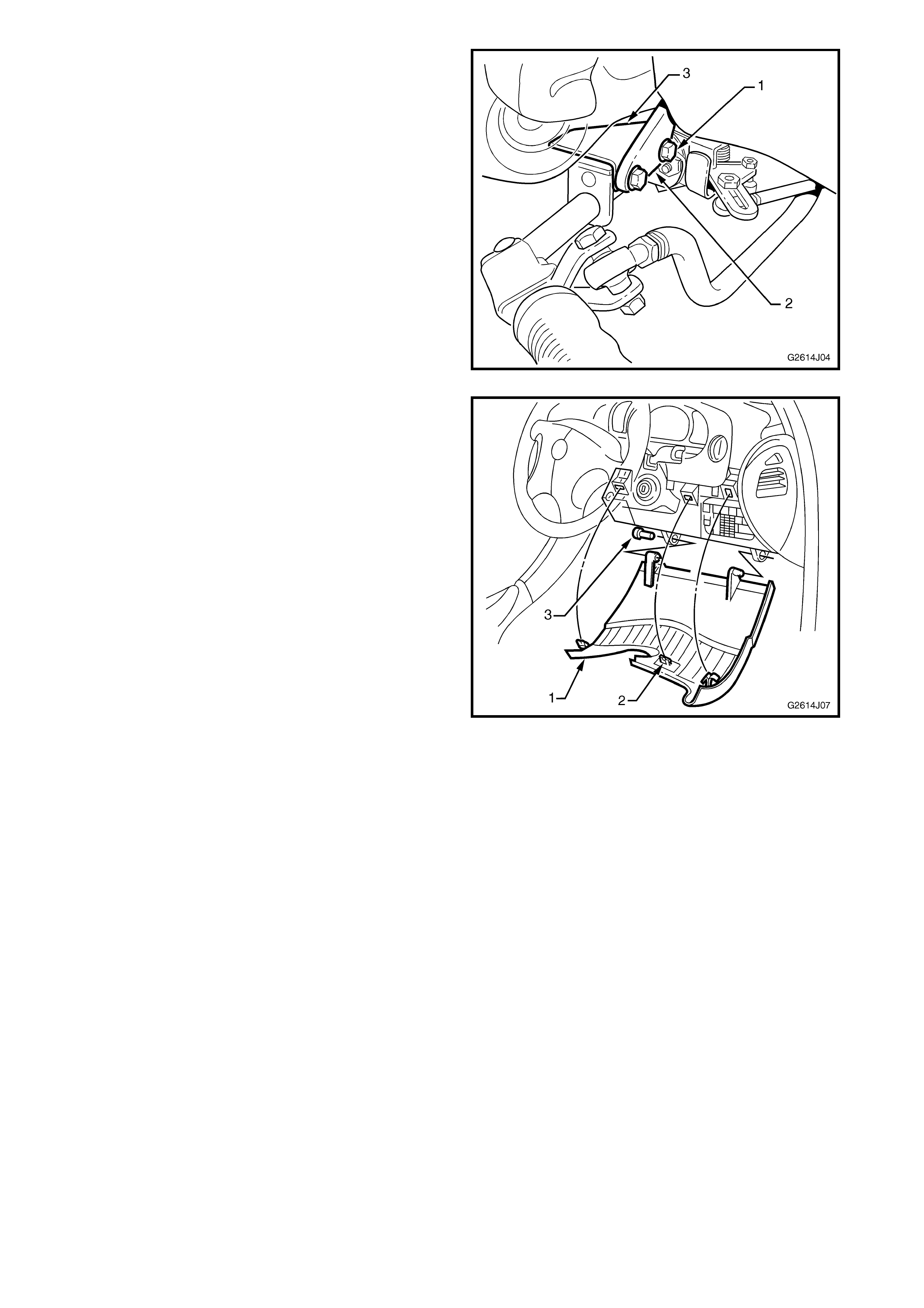
8. Open the fuse panel cover (1) by grasping each
top corner and pulling down, disengaging the
retainers (2), three places.
9. Remove the pin (3) and slide the fuse cover out of
its mounting.
Figure 4J-8
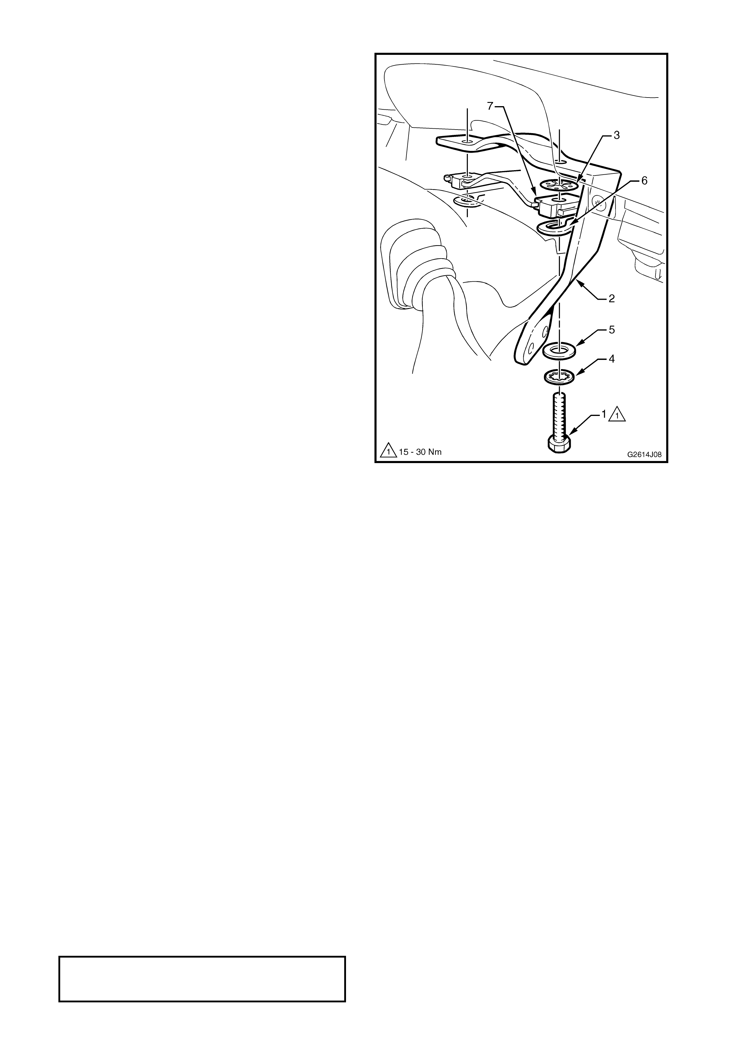
10. Undo bolt (1) attaching the mount bracket (2) to
the steering colum n m ount, lower the column and
remove the mount bracket.
NOTE: A retainer washer (3) is attached to the bolt
and will hold the bolt in place.
11. To remove mounting bolt, unscrew retainer (3)
and remove the bolt, shake-proof washer (4) and
flat washer (5).
Figure 4J-9
DISASSEMBLE
The components can be further disassembled if
required, refer 1.1 COMPONENTS for view of
components.
NOTE: To assist in assembly and adjustment, note
the position of locknuts, rose joints, etc. on their
threads prior to disassembly.
INSTALL
Mounting Bracket
1. Disconnect battery to disable the SRS air bag
system.
NOTE: Disconnecting the batter y will render the radio
inoperative until the correct security PIN code is
entered. Refer to the audio system operating
instructions provided with the vehicle owner’s
handbook for further information.
2. If not already done, undo bolts attaching steering
column upper mount and lower the steering
column.
3. If required, f it the bolt (1), shake-pr oof washer (4)
and flat washer (5) through the tilt spring (6) and
steering column upper mount (7). Attach the
retainer (3), refer Fig. 4J-9.
NOTE: The original 25 mm bolts are replaced with
longer 35 mm bolts when the hand control is fitted.
4. Fit the hand control bracket (2) between the
steering column and column mount bracket.
5. Raise the steering column into position and
tighten bolts to the specified torque.
STEERING COLUMN UPPER
MOUNT BOLT
TIGHTENING TORQUE 15 – 30 Nm
Fuse Panel Cover
NOTE: If a new fuse panel cover is supplied it will
require modifying.
1. Copy the template provided in Fig. 4J-17 and cut
along lines A & B.
2. Fold along lines C, D & E and place it on the fuse
panel cover as shown.
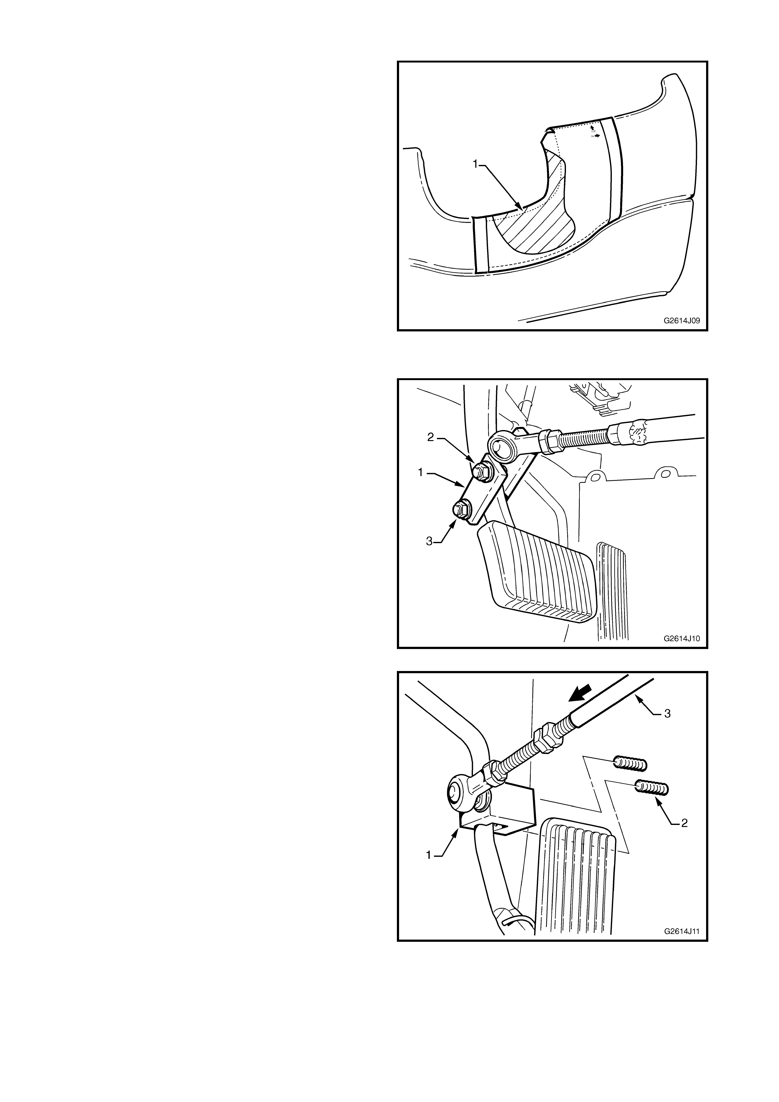
3. Mark around the area to be removed (1) and cut
the fuse panel cover to provide clearance for the
hand control assembly.
4. Fit the fuse panel cover in place and close, refer
Fig. 4J-8.
5. Trim the fuse panel cover as required and smooth
all sharp edges.
Figure 4J-10
Hand Control Assembly
1. Return the steering column adjustment to its
correct position, if it has been moved.
2. Lay hand control assembly on the driver’s floor.
3. Attach brake pedal clamp (1) to the brake pedal
arm, approximately 90 mm above brake pedal
pad.
4. Insert nut, bolt and washer (2).
5. Tighten bolts (2 & 3) securely.
Figure 4J-11
6. Depending on removal method, either:
• Attach the accelerator clamp (1) to the
accelerator pedal arm, as close to the pedal
as possible without interfering in its operation.
Tighten grub screws (2) securely, or
• Slide the linkage shaft (3) on to the end link.
7. Close fuse panel cover, if open.
Figure 4J-12
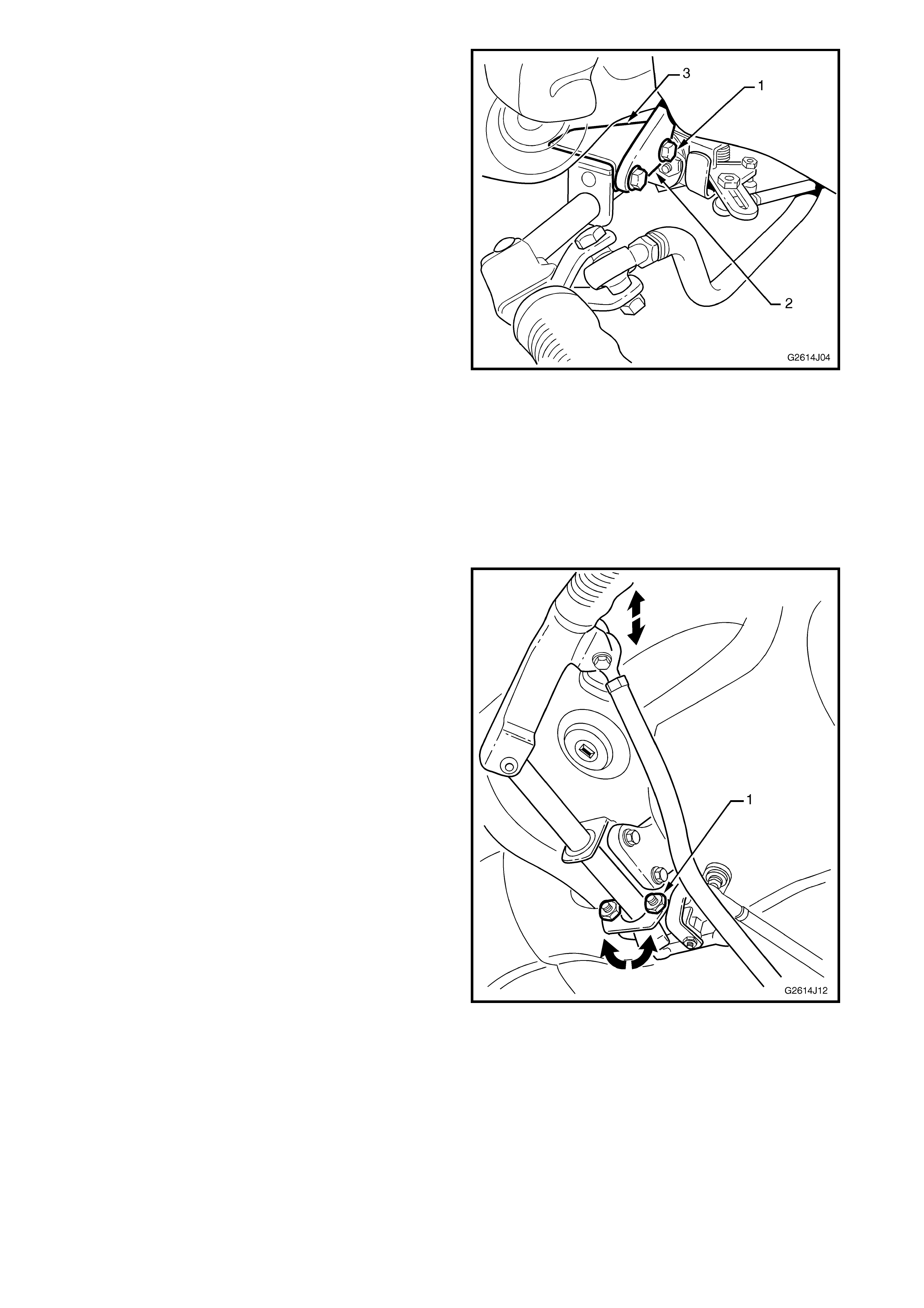
8. Raise the hand control assembly into position at
the mounting bracket (2) and fit the steering
column lever stop plate (3).
9. Insert bolts (1) and tighten securely.
10. Check correct operation, ensuring upon full travel
of the brake and accelerator pedals the
mechanism clears surrounding components and
the pedal pads. Adjust if required.
Figure 4J-13
ADJUST
Three main adjustments of the hand control are
provided which set the position of the lever. They
must be performed in the following order.
NOTE: The hand control is set to default factory
settings. Minor adjustments may be required to best
suit the driver’s requirements. Adjust only if
necessary.
Lever Height
1. Loosening bolt and nut (1), two places will allow
the lever to be rotated up or down as shown.
NOTE: The factory default position is the lever grip
set slightly above horizontal.
2. Retighten the bolts and nuts securely.
Figure 4J-14
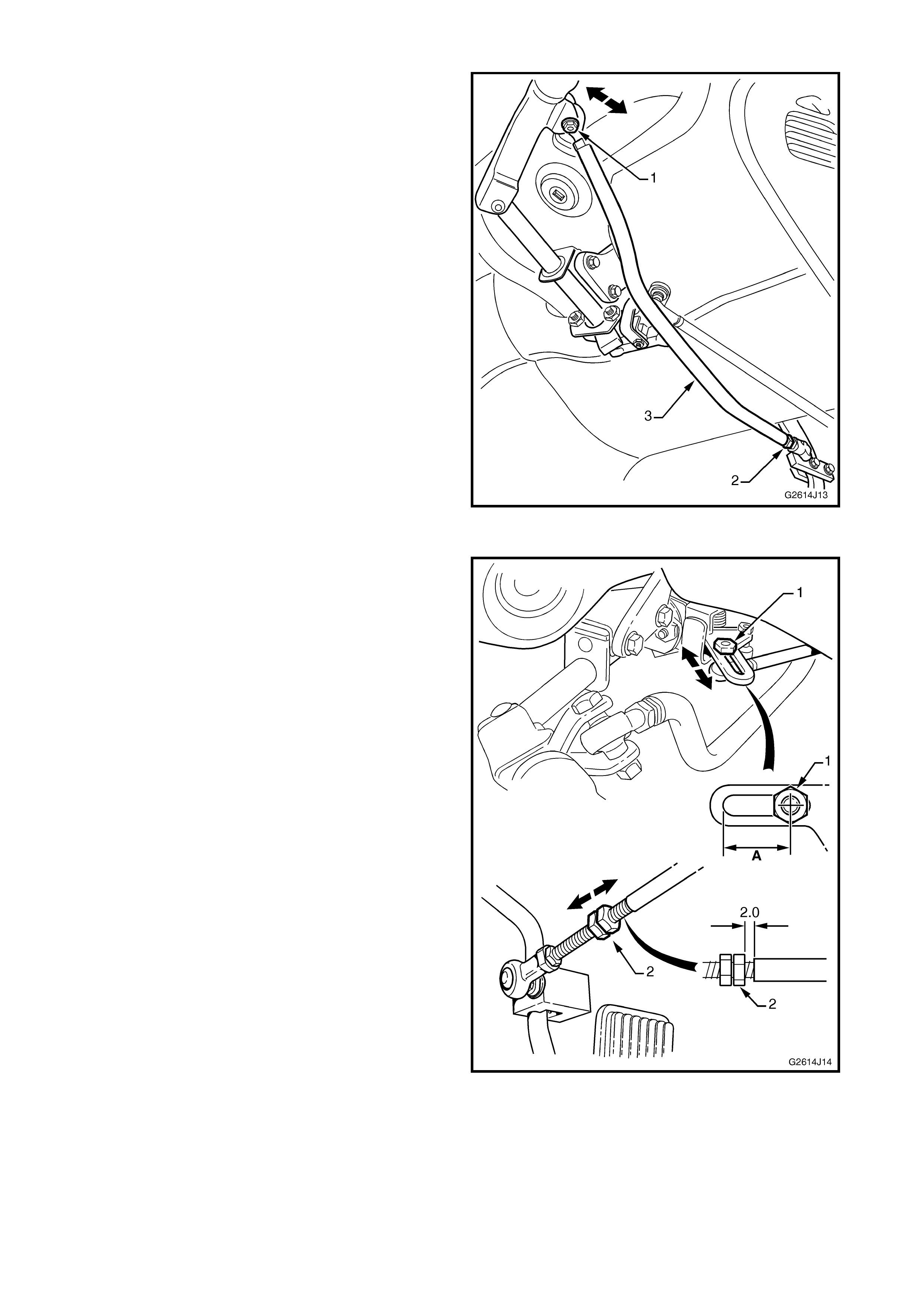
Brake Pedal Rod
This adjustment sets the distance of the lever from
the driver.
NOTE: The factory default setting is 50 mm from the
rear of the steering wheel rim.
1. Remove bolt and nut (1) from lever and remove
the brake pedal rod joint.
2. Loosen locknut (2).
3. Rotate the rod (3) to increase or decrease its
length. This will move the control lever closer or
further away from the driver.
NOTE: It may be helpful to have the driver seated in
their normal driving position while performing this
adjustment.
4. When desired lever position (factory default or
driver’s preferred position) is achieved, refit joint,
bolt and nut into lever and tighten securely.
5. Tighten locknut securely.
Figure 4J-15
Accelerator Pedal Rod
These adjustments are performed last and set the
amount of leverage required to operate the
accelerator and freeplay in the rod.
1. Loosen nut (1).
2. Slide the joint along the slot as required.
NOTE 1: Moving the joint closer to the assembly
results in less lever action being required to operate
the accelerator.
NOTE 2: The factory default dimension A is:
VT – 20 mm
WH – 35 mm
3. Tighten nut securely when the desired position is
achieved.
4. Loosen locknuts (2) and adjust until
approxim ately 2 mm freeplay is present when the
pedal is at rest.
5. Tighten locknuts securely.
6. Start vehicle and check for correct idle speed,
refer 2. MAINTENANCE in this Supplement.
Figure 4J-16
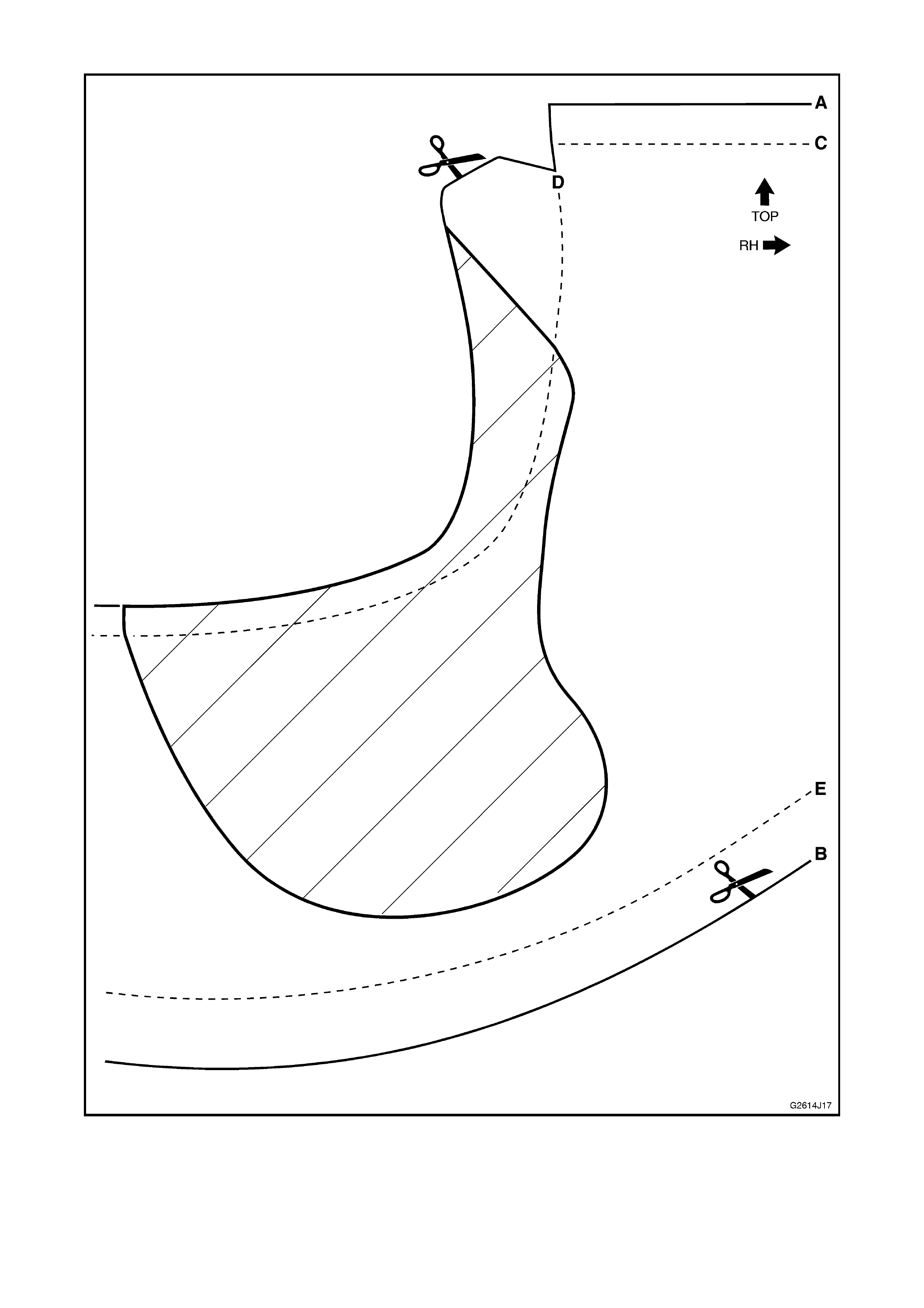
Fuse Panel Cover Template
Figure 4J-17
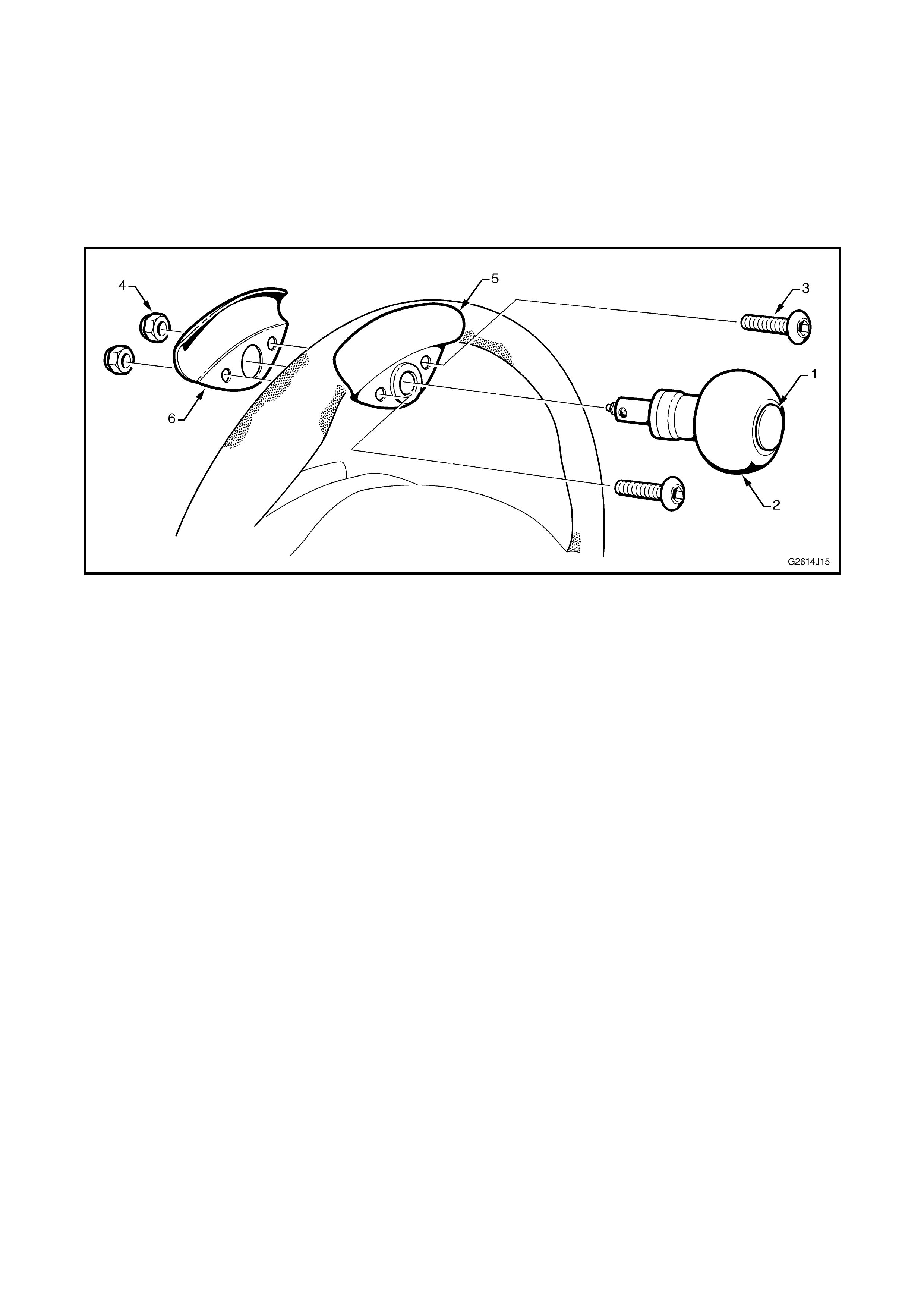
3.3 STEERING WHEEL KNOB
REMOVE
1. Depress button (1) in centre of knob (2) and
remove from mounting bracket.
2. Remove screws (3) and Nyloc nuts (4), two
places.
3. Remove mounting bracket sections (5 & 6).
Figure 4J-18
INSTALL
1. Align steering wheel in the straight-ahead
position.
2. Fit the m ounting brack ets to the steering wheel at
the 10 o’clock position.
NOTE: Ensure the front and rear sections are
positioned correctly and the rubber padding is
correctly seated.
3. Insert screws and Nyloc nuts, two places and
tighten securely.
4. Depress button in centre of k nob and fit the knob
into the mounting bracket.
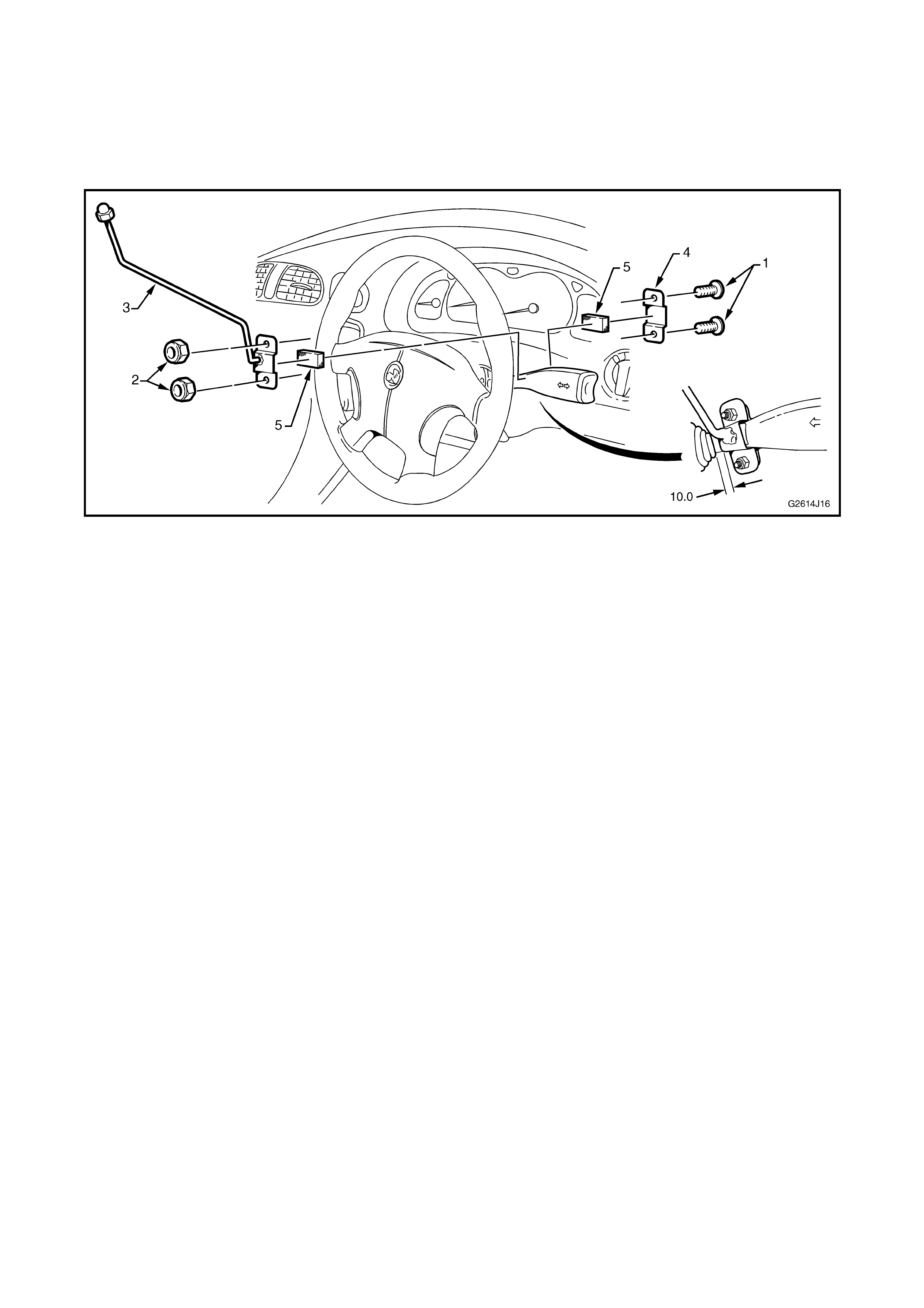
3.4 INDICATOR STALK EXTENSION
REMOVE
1. Remove screws (1) and nuts (2), two places.
2. Remove the extension (3) and bracket (4).
Figure 4J-19
INSTALL
1. Ensure foam-padding (5) is seated in the indicator
stalk extension and bracket.
2. Position the extension on the indicator stalk
approximately 10 mm from the rubber boot.
3. Fit brack et to the ex tens ion and ins ert s c rews and
nuts as shown and tighten nuts securely.
NOTE: Ensure foam is seated correctly on stalk.
4. If required bend the extension to best suit the
driver’s requirements.