
SECTION 5A - VS SERIES ID UTILITY & ASSOCIATED
COMPONENTS
CAUTION:
This vehicle may be equipped with a driver’s side only or driver’s and front passenger’s side Air
Bags. An AIR BAG is a Supplemental Restraint System (SRS). Refer to CAUTIONS, Section 12M in
Volume 4 of the VS Series Service Manual, before performing any se rvice operation on or around SRS
components, the steering mechanism or wiring. Failure to follow the CAUTIONS could result in air
bag deployment, resulting in possible personal injury or unnecessary SRS system repairs.
CAUTION:
This v ehicle may be equipped w ith LPG ( Liquefied Pet roleum Gas). In th e interests of safet y, the LPG
fuel system should be isolated by turning 'OFF' the manual service valve and then draining the LPG
service lines, before any service work is carried out on the vehicle. Refer to the LPG leaflet included
with the Owner's Handbook for details or Volume 6 of the VS Series Service Manual for more specific
servicing information.
1. GENERAL INFORMATION
This Section of the Holden By Design Service Information Supplement describes the removal and installation
procedures for the VS Series utility id package and associated components.
The utility id package consists of components designed to enhance and add sporting character to the Holden
utility. The standard pack age consis ts of a unique single opening grille, five spok e alloy wheels and lowered FE2
suspension.
Where the id package is optioned on a standard model utility, the bumper bars are painted the vehicle body
colour.
A Holden By Design identification plate, decals and id badging complete the package.
A limited edition id utility marketed late 1998, also included a leather bound steering wheel, transmission knob
and handbrake lever handle. The service of these components and the FE2 suspension is the same as the
standard components fitted to VS Series Vehicles and is not shown in this section.
In addition, other components can be added or optioned individually to further enhance the vehicle.
These include:
• Rigid tonneau,
• Cargo liner,
• 185 kW V8 engine,
• Alloy wheels of a different style.
The rigid tonneau is hinged at the front and can be easily raised from the rear with the assistance of two gas
struts. A keyed lock is provided on each side to ensure valuable items are kept safe.
The Holden By Design cargo liner is constructed from high density polyethylene. It consists of two parts; one
covering the inner tailgate skin and the other covering the entire cargo area, sides and bulkhead.
Developed by Holden Special Vehicles, the 185 kW V8 engine incorporates modifications to the inlet, exhaust
and engine management systems.
For information not contained in this Section, refer to the relevant VS Series Service Manual.
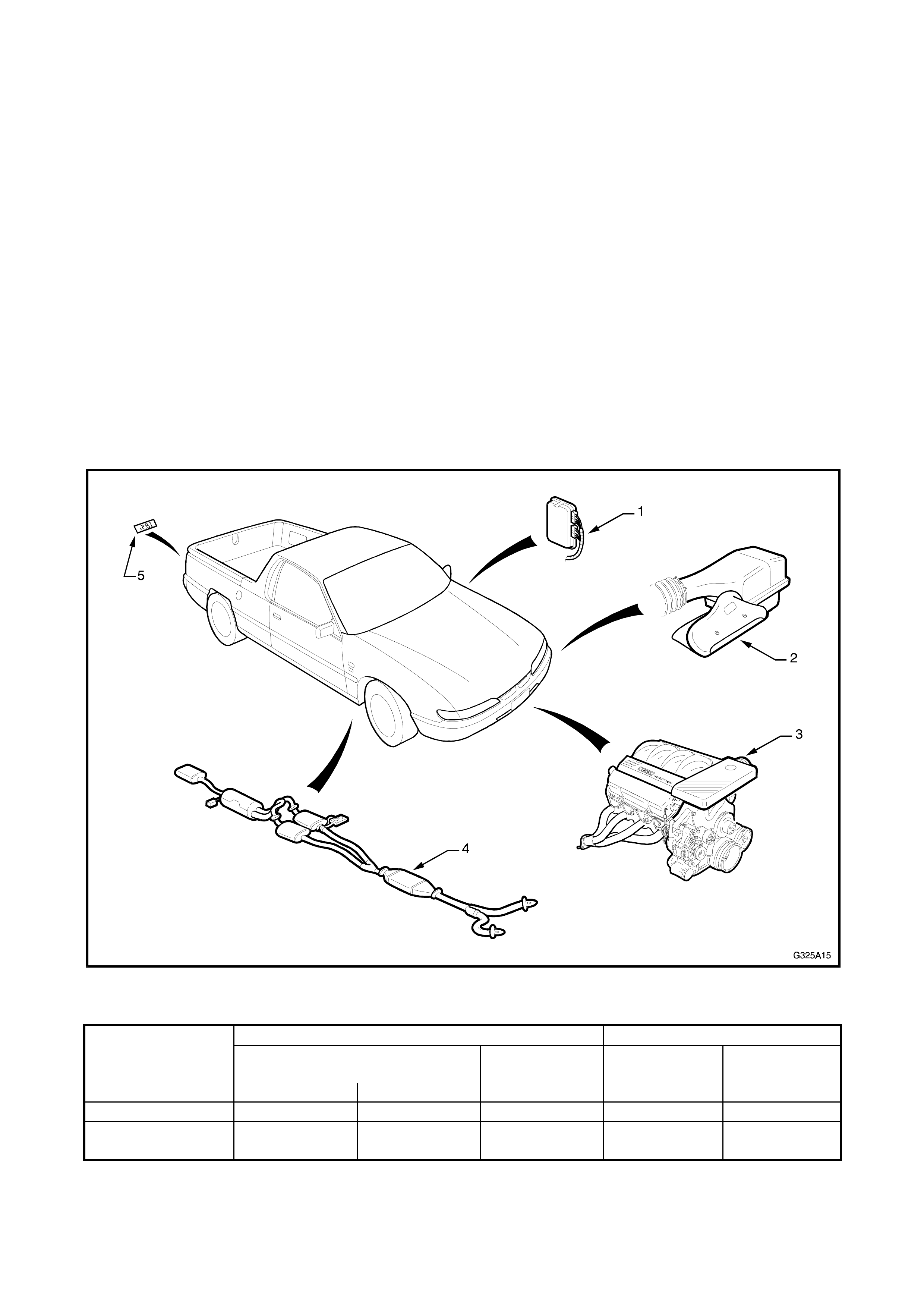
Fig. 5A-1 illustrates the major components available for the VS Series Utility.
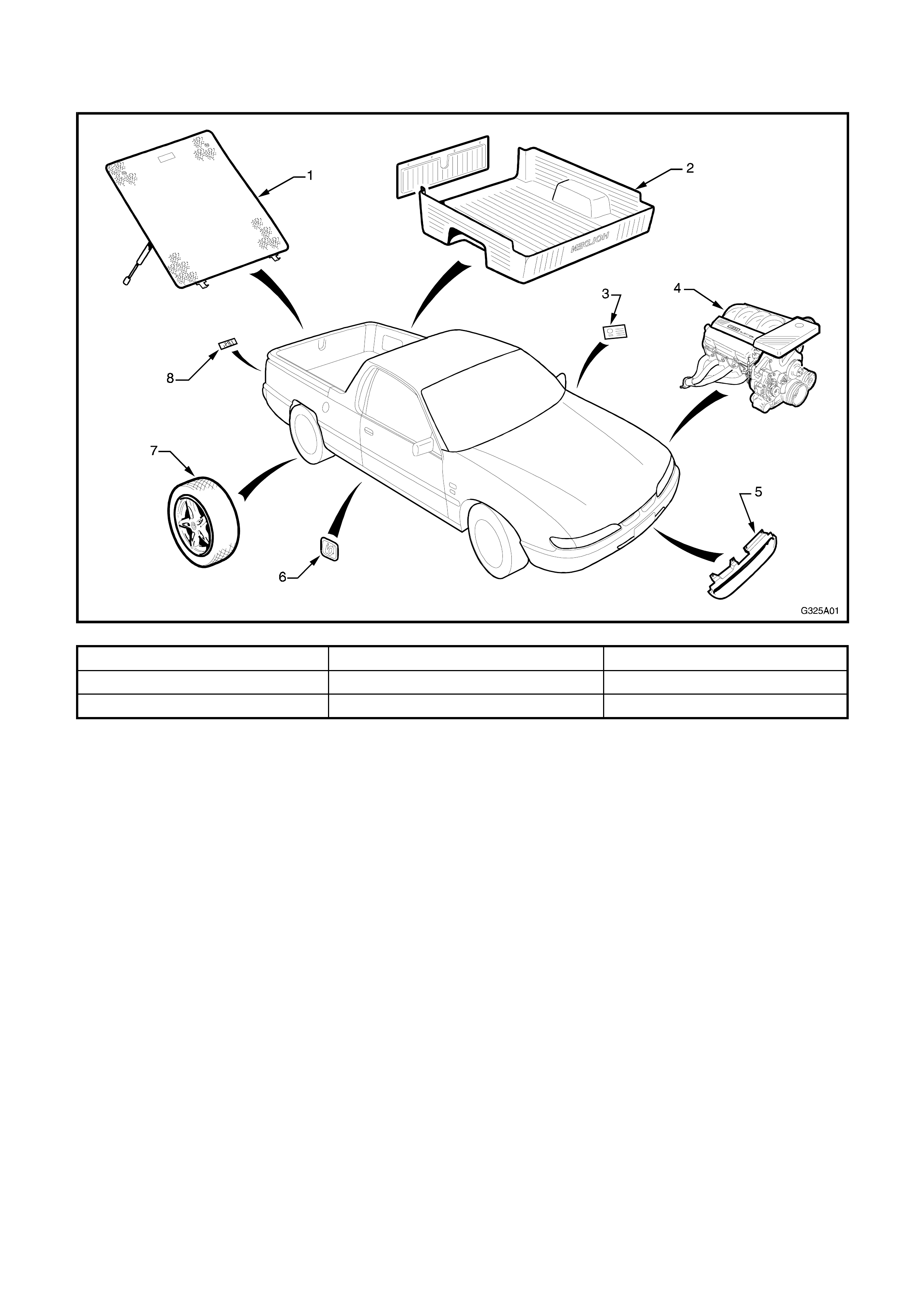
1.1 MAJOR COMPONENTS
Figure 5A-1
1. Rigid tonneau 4. 185 kW V8 engine 7. Alloy wheel
2. Cargo liner 5. Sports grille 8. 185i emblem
3. HBD identification plate 6. id badge
2. ID SPORTS GRILLE
The id sports grille replaces the standard VS Series twin
grille inserts. If the front bumper facia is being replaced,
the new facia will require modifying to accommodate the
id sports grille insert. Refer to Section 1D, BUMPER
BARS in Volume 1 of the VR Series Manual for the
bumper facia removal procedure, if required.
NOTE: The id sports gr ille is painted in the vehic le’s body
colour. The painting procedures are relatively straight
forward, providing the c orrec t steps are f ollowed. Ref er to
Section 1D, BUMPER BARS in Volume 1 of the VR
Series Manual for further information.
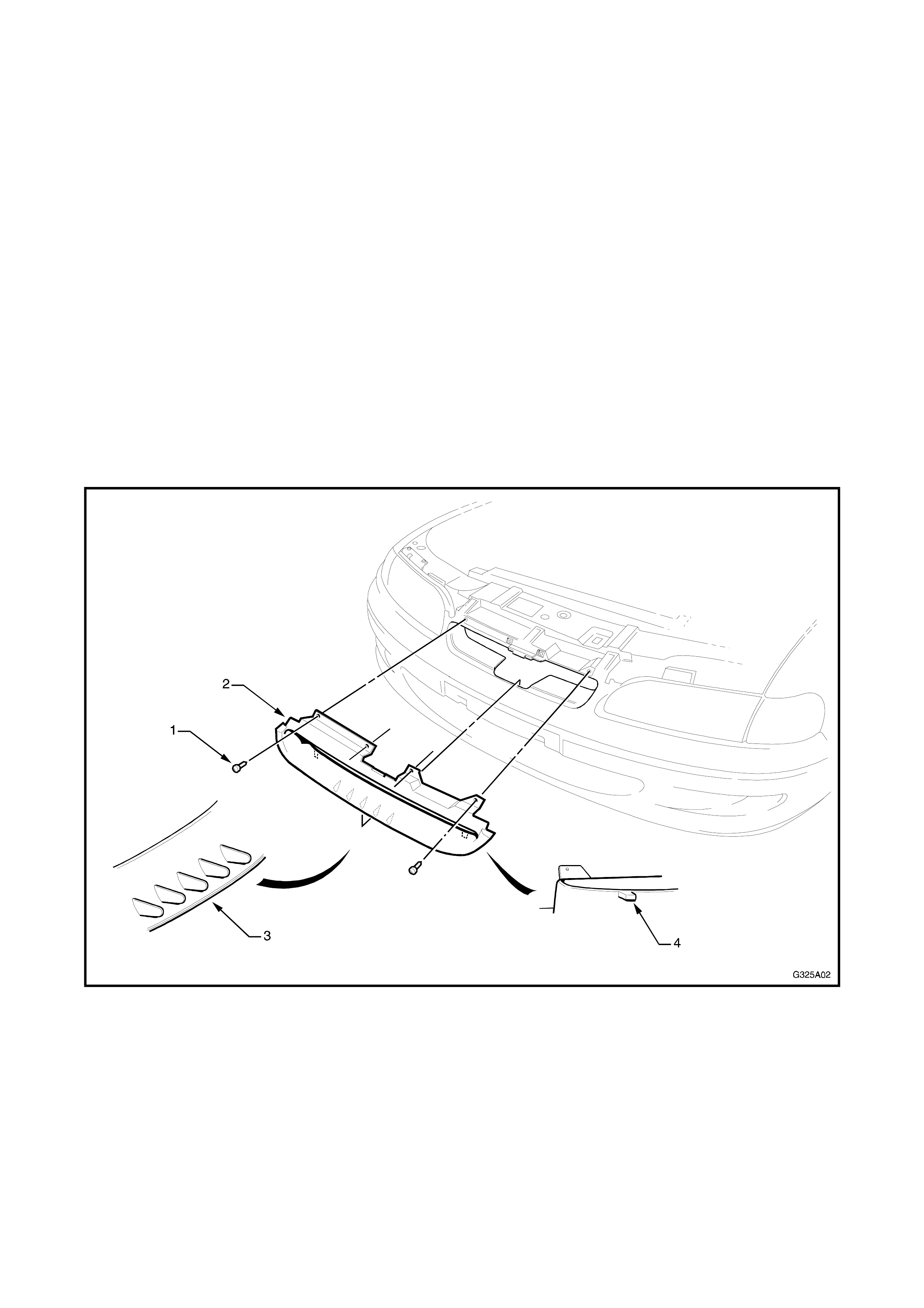
REMOVE
1. With the engine hood raised, remove the four
screws (1) securing the id sports grille (2) to the
bumper facia.
2. Remove the grille by lifting it up and out to
disengage the lugs (3) and (4) f rom the lower and
rear edges of the bumper facia.
Figure 5A-2
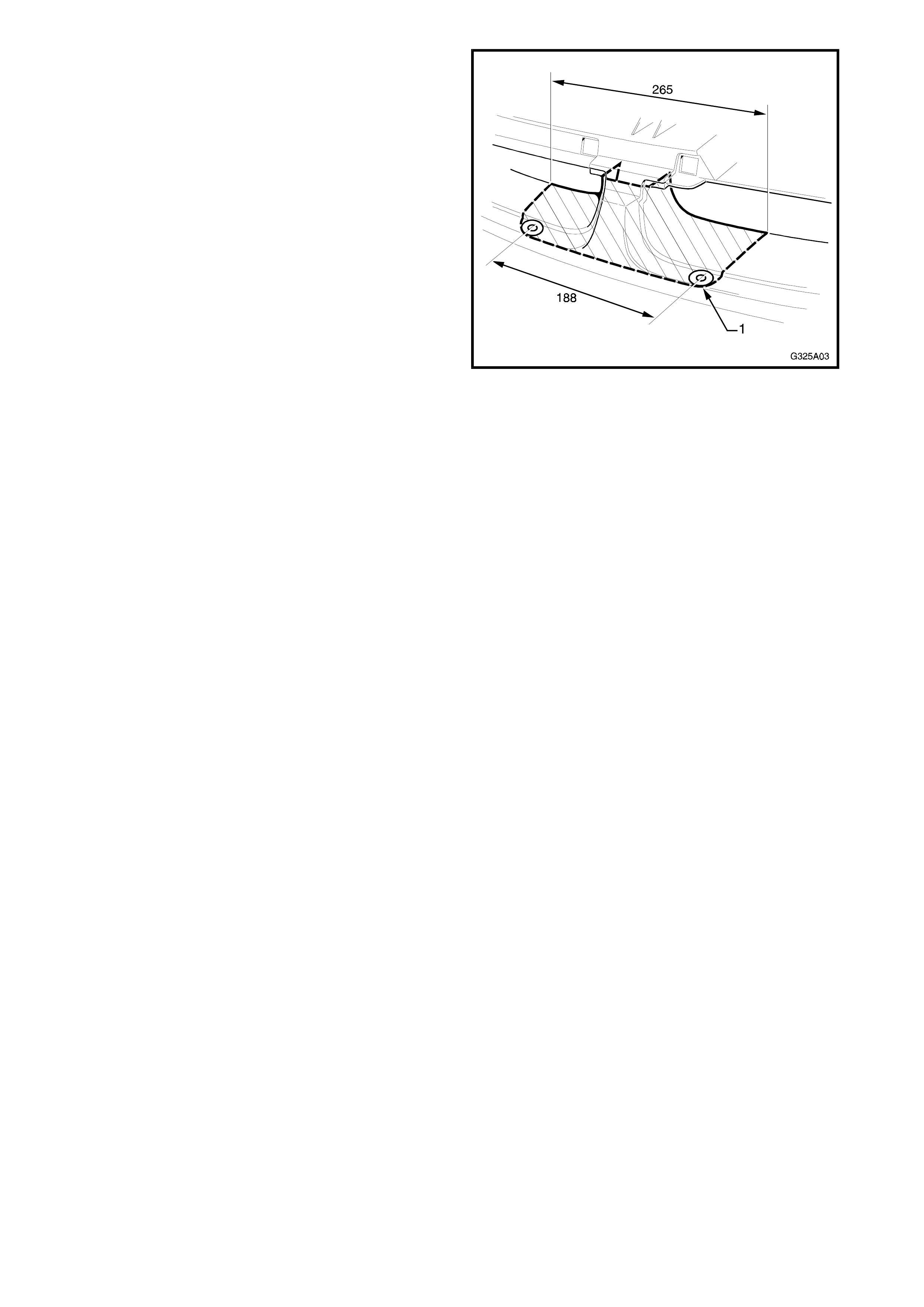
INSTALL
1. If the bumper facia was not replaced, proceed to
Step 6.
2. Determine the centre of the grille openings and
mark the bumper facia with the cutting locations
as shown.
3. To obtain the radius (1), drill a 3 mm pilot hole
and enlarge it to 18 mm.
4. Carefully cut along the cutting marks with a
hacksaw or like.
NOTE: It is advisable to leave excess material and
file the facia to suit the grille.
5. Check fit of the id sports grille, ensur ing the tangs
(3) and (4) in Fig. 5A-2 locate correctly.
6. Install the id sports grille by inserting the lower
edge in the bumper opening and rolling the upper
edge back.
7. Ensure the locating tangs have seated correctly.
8. Install the four screws.
Figure 5A-3
3. RIGI D TONNEAU
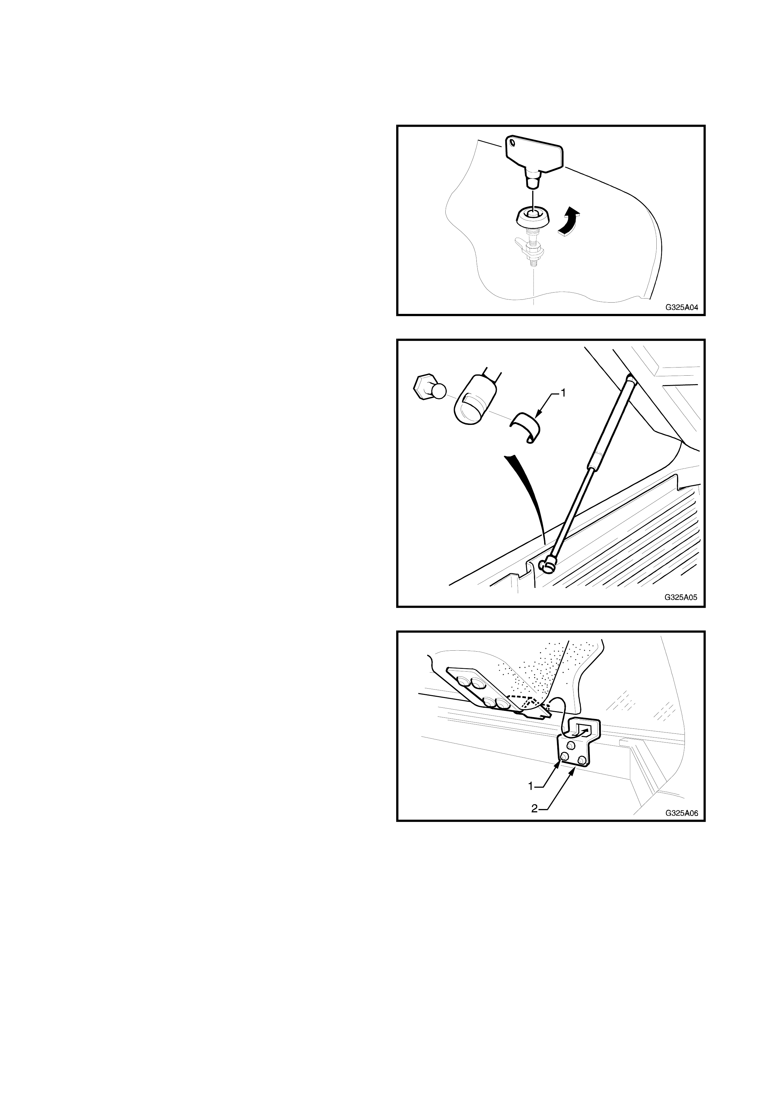
REMOVE
1. Using the special key, unlock both sides of the
rigid tonneau.
Figure 5A-4
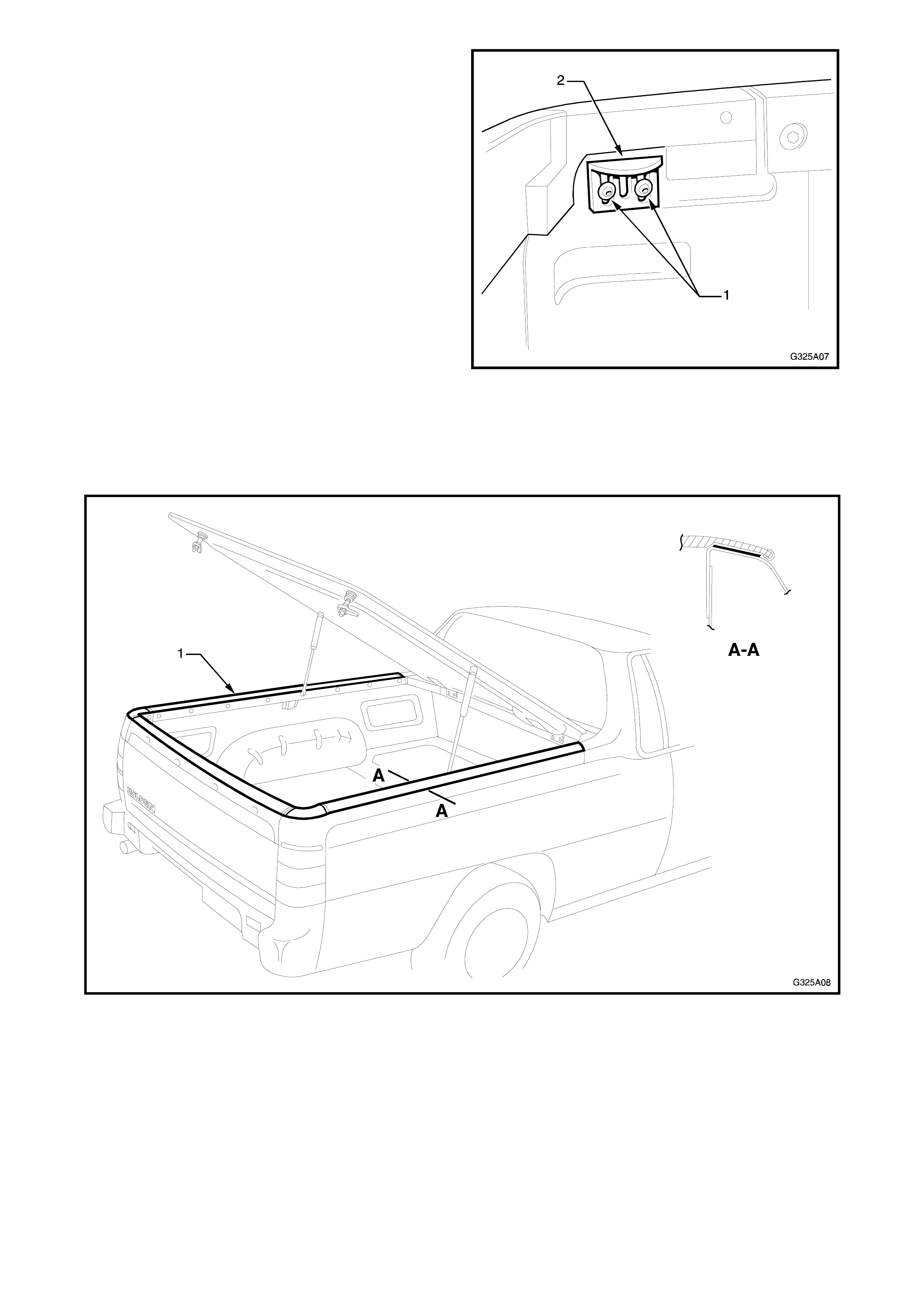
2. Support the rear of the rigid tonneau with the aid
of an assistant and remove the gas strut from
each side of the vehicle body by rem oving the clip
(1).
Figure 5A-5
3. Raise the rigid tonneau to nearly vertical and
disengage the hinges.
NOTE: Take care not to damage the paintwork.
4. If required, remove the three bolts (1) attaching
each hinge plate (2) to the load compartment
front upper panel.
Figure 5A-6
5. If required, remove the two bolts (1) attaching the
lock plate (2) to each side panel inner.
NOTE: M6 Nutserts are used to provide the screw
thread for the lock and hinge plate bolts. If a panel is
replaced a Nutsert gun will be required to attach these
to the vehicle body.
Figure 5A-7
6. If required, remove the desired section(s) of
urethane protection film from the areas shown in
Fig. 5A-8, by carefully peeling the film away from
the paint surface.
NOTE: Use of a hot air gun may aid removal.
Figure 5A-8
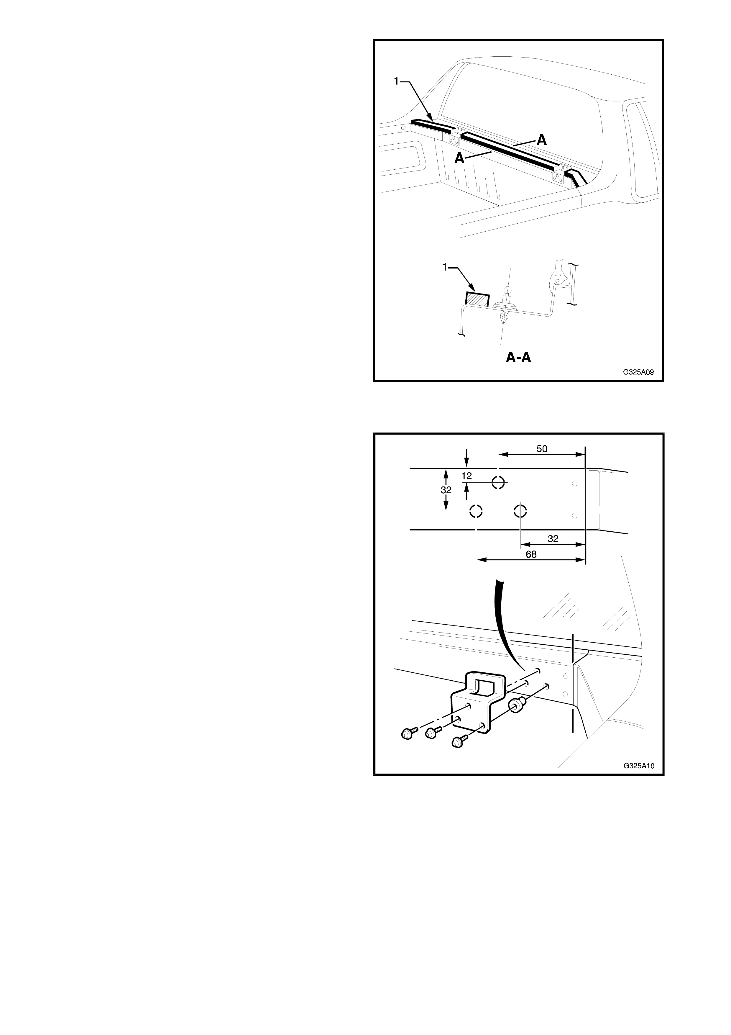
7. If required, remove the front seal (1) by carefully
peeling and scraping it away from the body .
Figure 5A-9
INSTALL
Hinge plates
1. If the load compartment front upper panel was
replaced, drill three 6 mm holes followed by 9.5
mm holes as shown for the hinge plates.
2. Using a nutsert gun, inser t a M6 nutsert into each
hole.
3. Fit the hinge plate and install the three bolts.
Figure 5A-10
Front seal
1. Affix the front seal as shown in Fig. 5A-9.
NOTE: If the old seal is to be reused, use a contact
adhesive to adhere the seal. Ensure the directions
supplied with the adhesive are followed.

Lock plates
1. If a side panel inner was replac ed, drill two 6 mm
holes followed by 9.5 mm holes for each lock
plate as shown.
2. Using a nutsert gun, inser t a M6 nutsert into each
hole.
3. Temporarily fit the lock plate, leaving final
adjustment until all of the components are
installed.
Figure 5A-11
Rigid tonneau
1. With the aid of an assistant, lift the rigid tonneau
into position. Raise the rear to nearly vertical and
carefully engage the hinges in the hinge plates.
2. Have the assistant support the rigid tonneau and
fit the gas struts as shown in Fig. 5A-5.
NOTE: The struts must be fitted with the cylinder up
as shown to ensure correct operation.
3. Check the operation of the rigid tonneau,
ensuring it seats correctly and does not bind the
front seal.
4. Close each of the locks. Raise the tonneau and
note the amount that the tonneau raises.
5. Lower the locking plate by that amount.
6. Recheck the operation of the lock, ensuring it
does not bind on the locking plate. Readjust as
necessary.
Urethane protection film
NOTE 1: The following instruc tions mus t be r ead prior
to beginning the installation of the ur ethane protection
film.
NOTE 2: T he urethane pr otection film s hould be f itted
once the rigid tonneau has been installed.
1. Close the rigid tonneau and m ark its per im eter on
the vehicle with a pencil or like. Install the film
within the pencil mark, ensuring the f ilm does not
cover the pencil mark. Also refer to Fig. 5A-8.
2. For best res ults, the f ilm and surf ace to which it is
to be applied should be between 15° and 32°
Celsius.
3. The body surface must be clean and devoid of
surface contaminants. This can be accomplished
by wiping the application area with a 50/50
solution isopropyl alcohol and water, followed
immediately with a dry wipe.
4. Place the film face down on a flat surface.
Remove the liner at an angle of approximately
180°.
NOTE: Take care not to touch or contaminate the
adhesive.
4. A wet application method is r ecommended. Us e a
solution of 25% isopropyl alcohol and 75% water.
Spray the entire film surface and the vehicle
surface where the film is to be applied.
NOTE 1: Do not use detergent and water.
NOTE 2: A dry application may result in a hazy
appearance of the film.
5. Carefully place the film in place, ensuring it is
correctly aligned. Refer Fig. 5A-8.
6. Use a plastic squeegee (3M part No. PA-1 B or
PA-1 G recommended) with a low friction sleeve
(3M part No. SA-1) to press the film in place,
forcing out the entrapped air or excess wetting
solution.
NOTE: T he f ilm may be gently heated with a heat gun
to assist conforming the film with difficult contours.
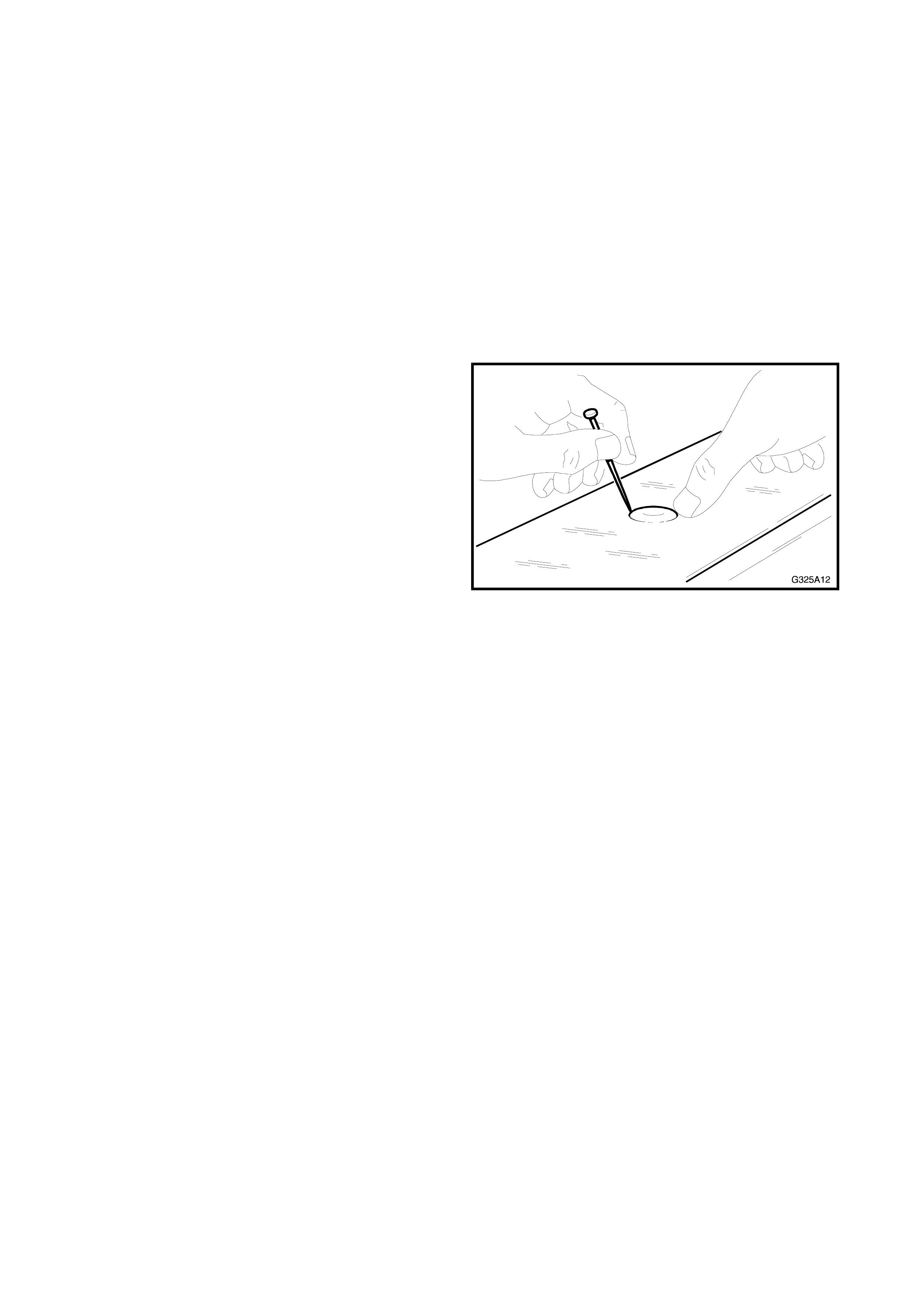
7. Air bubbles that cannot be removed with the
squeegee can be removed by carefully piercing
the air bubble with a pin at its circumference.
Gently push the air toward the hole with your
finger.
Figure 5A-12
4. CARGO LINER
REMOVE
Tailgate section
1. Open the tailgate and remove the tailgate inner
handle.
2. Remove the eight screws (1) attaching the
tailgate liner (2) to the tailgate inner.
NOTE: Scrivets may be used in place of the four
lower screws on early models.
3. Remove the tailgate liner and upper finishing s trip
(3).
Figure 5A-13
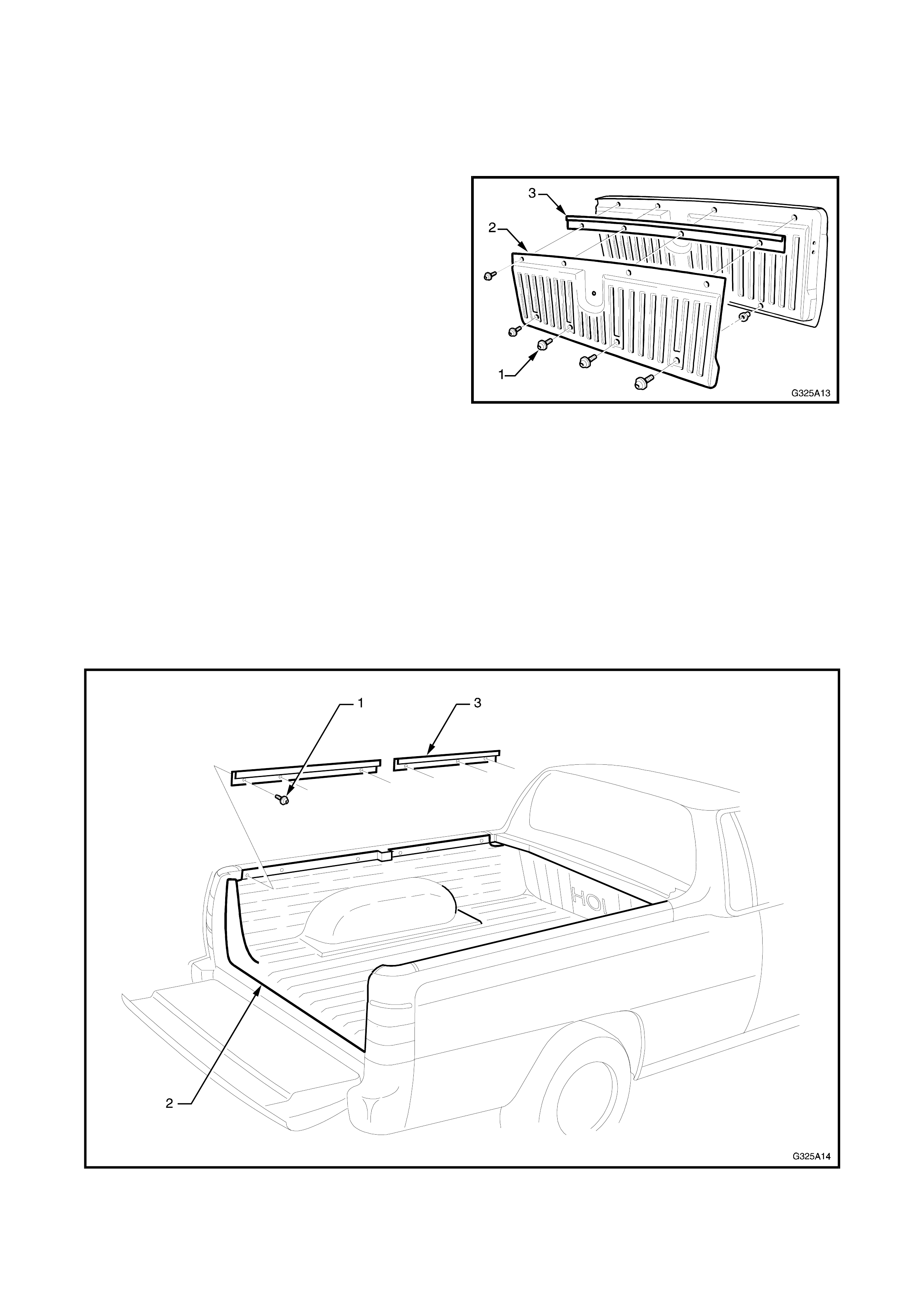
Cargo section
NOTE: If fitted, remove the rigid tonneau prior to
rem oving the cargo liner, r efer 3 RIGID TONNEAU in
this Section.
1. Remove the six screws (1) from each side,
attaching the cargo liner (2) to the side panel
inner as shown in Fig. 5A-14.
2. Remove the two finishing strips (3) from each
side of the cargo liner.
3. With the aid of an assistant, remove the cargo
liner by lifting it up at the rear and sliding it
rearwards.
Figure 5A-14

INSTALL
Tailgate section
1. If the tailgate has been replaced, place it in the open position and sit the tailgate liner in position.
2. Temporarily install the two outer upper screws.
3. Mark the position of the lower screws and remove the liner.
4. Drill the four lower screw holes using a 6 mm drill bit followed by an 11 mm drill bit.
5. Using a nutsert gun, insert a M8 nutsert into each hole.
6. Fit the finishing strip on to the upper edge of the liner, ensuring the screw holes align.
7. Place the liner in position on the tailgate and fit the eight screws. Refer Fig. 5A-13.
8. Refit the tailgate handle and chec k the tailgate for correc t operation, ensuring the liner does not bind or rub
against any adjacent panels.
Cargo section
1. Ensure the cargo area is clean and dry.
2. W ith the aid of an ass istant, install the cargo liner by lifting it into the cargo ar ea over the wheel arches and
tilting the rear up to enable the front to be slid under the bulkhead.
3. Fit the two upper finishing strips each side, and loosely fit each screw. Refer Fig. 5A-14.
NOTE: If the vehicle is fitted with a rigid tonneau, the gas strut ball s ocket is plac ed in the rear hole of the f ront
upper finisher.
4. Tighten the screws and check the operation of the tailgate, ensuring it doesn’t bind with the cargo liner.
5. 185 KW V8 ENGINE
This Section of the Holden By Design Service Information Supplement describes the components employed in
the 185 kW V8 engine upgrade.
The 185 kW V8 engine has been developed by Holden Special Vehic les and includes a revis ed air inlet system,
a new exhaust system and a recalibrated powertrain management system.
Together, these modifications increase the power output to 185 kW @ 4800 rpm and torque output to 400 Nm
@ 3600 rpm.
A Holden By Design identification plate and 185i badging completes the package, which is described in 7,
IDENTIFICATION & BADGING in this Section.
Fig. 5A-15 illustrates the 185 kW V8 engine major components.
The table below provides identif ication details for the engine control m odule ( ECM) fitted to m anual tr ansm iss ion
185 kW V8 vehicles and the powertrain control module (PCM) fitted to automatic transmission 185 kW V8
vehicles.
The Holden By Design 185 kW V8 engine exhaust system replaces the standard V8 exhaust and is a low
restriction, free flowing design. Although service procedures are the same as the standard exhaust system , the
clearances differ, which are shown in Fig. 5A-16.
All other service procedures for the Holden By Design 185 kW V8 engine are the same as the standard V8
engine components. Refer to the relevant Section of the VS Series Service Manual.
Figure 5A-15
ECM/PCM MEMCAL
DELCO ID HSV SERVICE DELCO ID HSV
SERVICE
P/N B/C P/N P/N PART NO.
185 Manual ECM 16192428 BFPM 12F-651901 16192420 12F-651903
185 Automatic
PCM 16239998 BWCS 12F-950114 16239973 12F-950115
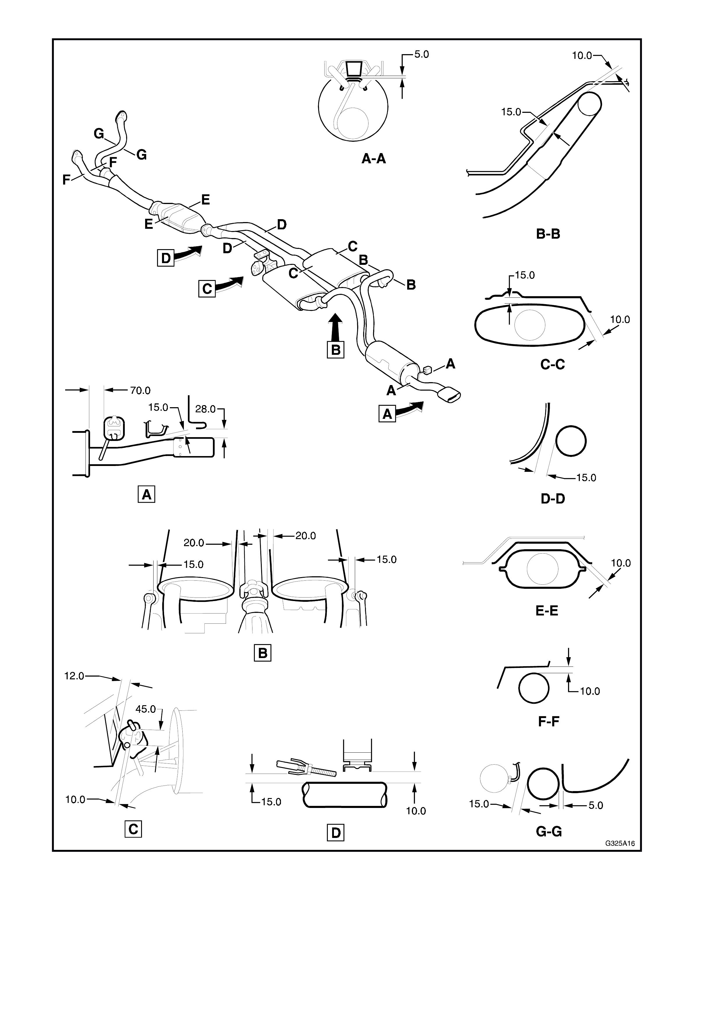
Figure 5A-16
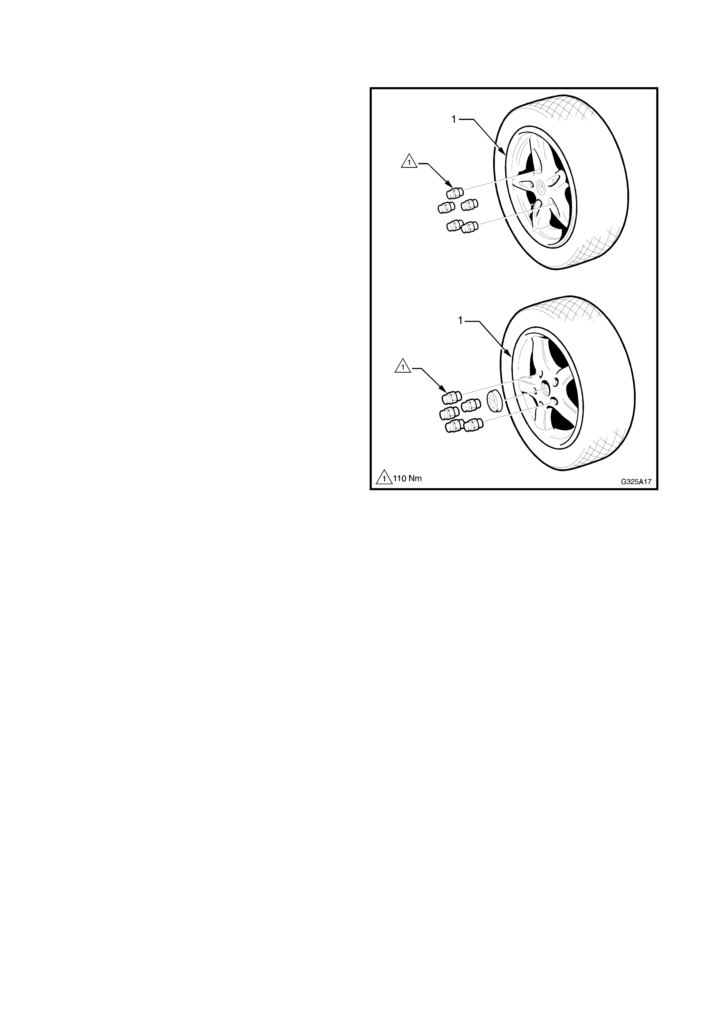
6. ALLOY WHEELS
Two alloy wheel styles are available for Holden By
Design VS Utility Vehicles. Both have a 16” diameter
and are 7” wide.
While wheel nuts designed for use with alloy wheels
are fitted, the wheel studs remain the same as
standard VS Series Vehicles. The standard spare
wheel is not changed.
This Section of the Holden By Design Service
Information Supplement illustrates the wheel types
only. For the information required to service wheels
for VS Series Vehicles, refer to Section 10, W HEELS
& TYRES in Volume 4 of the VS Series Service
Manual.
Figure 5A-17
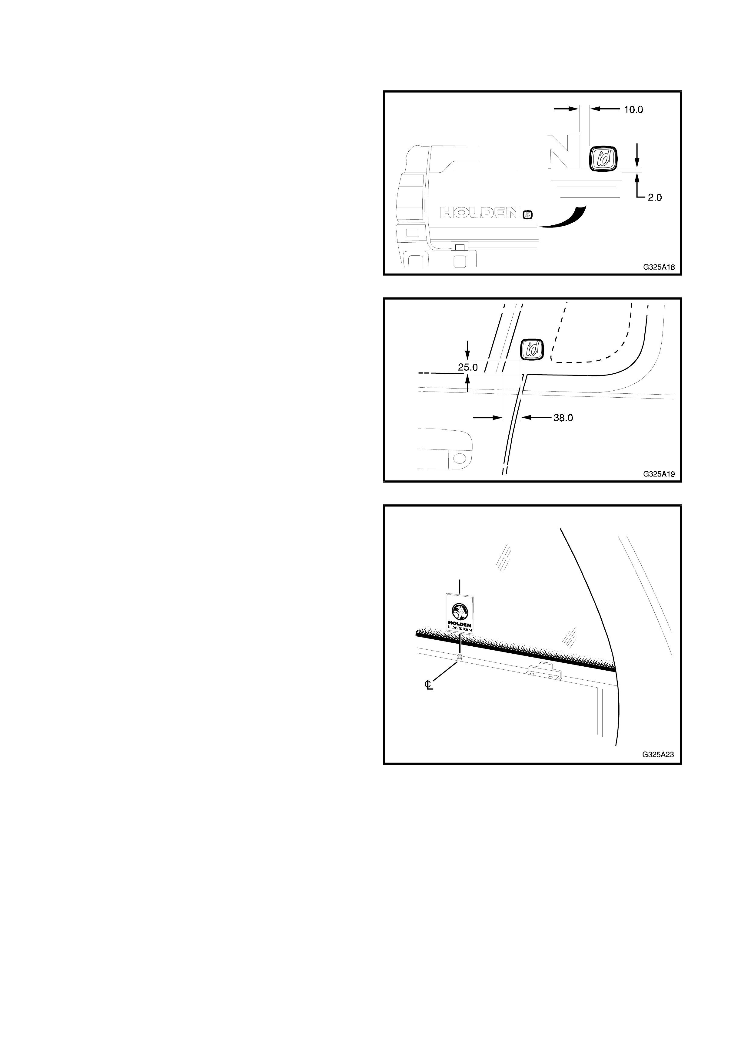
7. IDENTI FICATION & BADGING
All Holden By Design VS Series id utilities are fitted
with unique id badging which is affixed to the tailgate
and each side quarter glass as shown in Figs. 5A-18
and 5A-19.
Figure 5A-18
Figure 5A-19
A Holden By Design decal is affixed to the rear
window. It is placed just above the edge of the
ceramic band, in line with the third tonneau cover
retainer.
NOTE: Some earlier vehicles had the decal aligned
with the second tonneau cover retainer or rigid
tonneau hinge centre.
Figure 5A-20
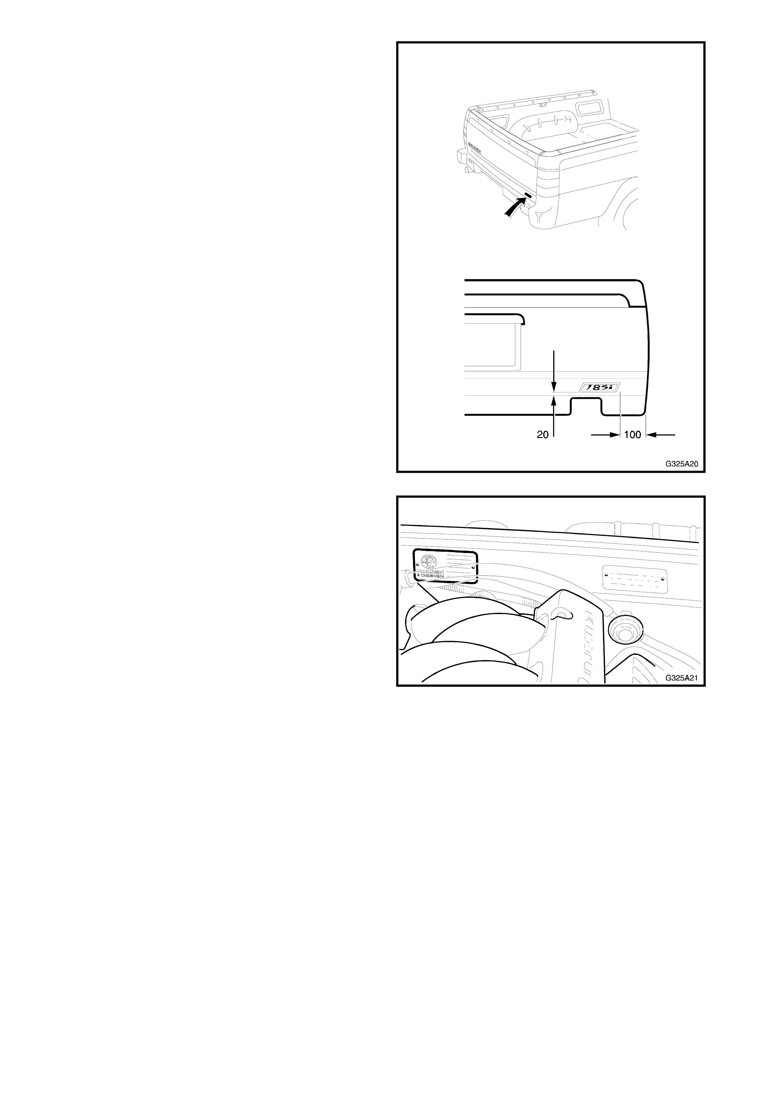
Vehicles fitted with the 185 kW V8 engine, receive a
unique 185i decal, which is affixed to the tailgate as
shown.
Figure 5A-21
A HBD identification plate is installed onto the dash
panel with pop-rivets.
Figure 5A-22