SECTION 5B - VS SERIES CONVENIENCE &
COUNTRY DRIVING
CAUTION:
This vehicle may be equipped with a driver’s side only or driver’s and front passenger’s side Air
Bags. An AIR BAG is a Supplemental Restraint System (SRS). Refer to CAUTIONS, Section 12M in
Volume 4 of the VS Series Service Information, before performing any service operation on or around SRS
components, the steering mechanism or wiring. Failure to follow the CAUTIONS could result in air
bag deployment, resulting in possible personal injury or unnecessary SRS system repairs.
1. GENERAL INFORM ATION
This Section of the Holden By Design Service Information Supplement describes the VS Series convenience and
country driving packages which consist of:
• Cruise control,
• Power antenna, and
• Country roo bar.
Cruise control is available on vehicles with automatic transmission only. The Holden By Design system utilises
the standard VS Series cruise control components and fully integrates them with the vehicle via a patch wiring
harness.
The power antenna offers automatic extension and retraction when either the ignition or radio is switched on or
off, protecting it from damage while the vehicle is parked.
The country roo bar has been designed to fully integrate with the VS Series’ safety systems and will not affect
the operation of the airbag.
For information not contained in this Section, refer to the relevant VS Series Service Information.
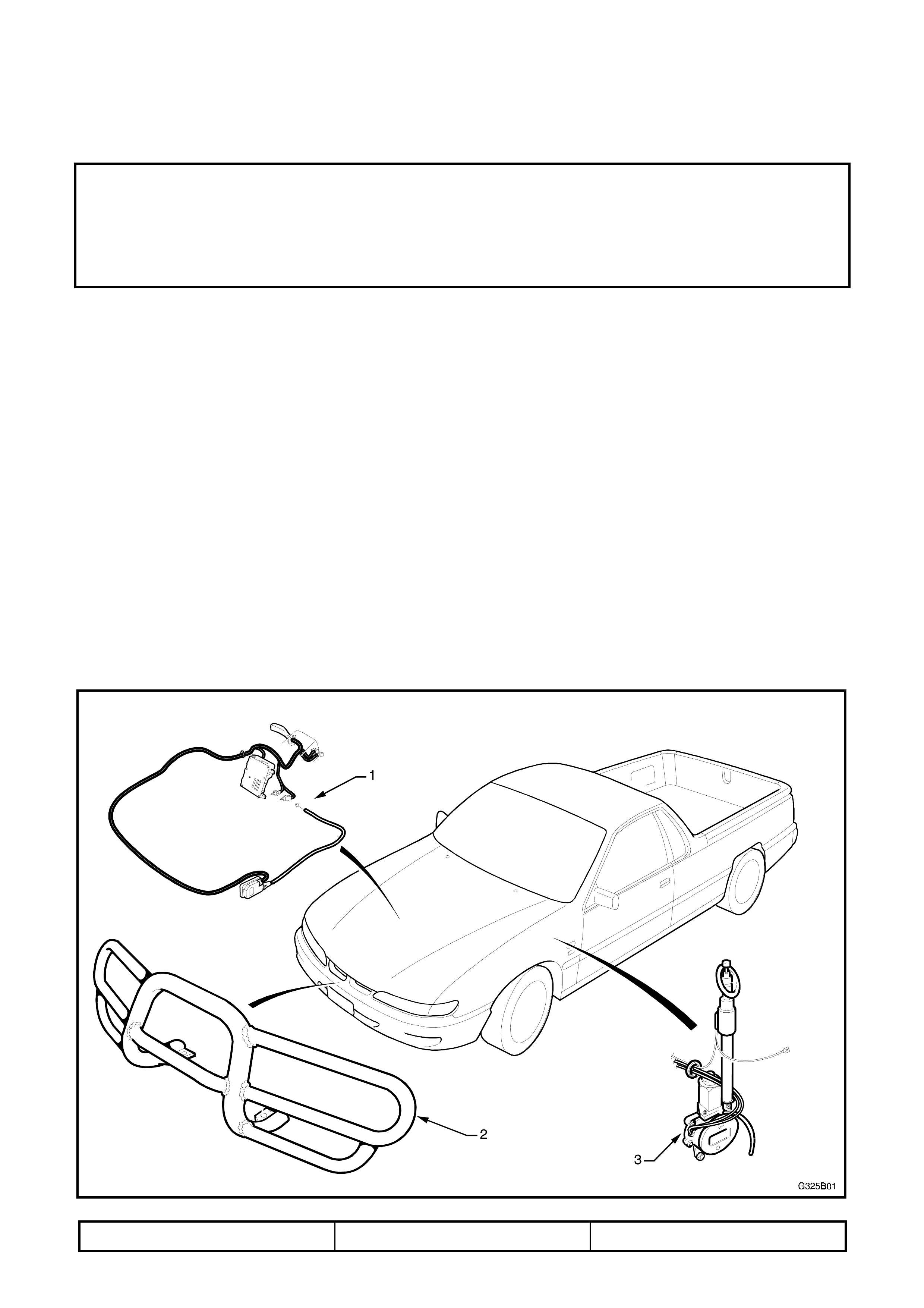
Fig. 5B-1 illustrates the VS Series convenience and country driving major components.
1.1 MAJOR COMPONENTS
Figure 5B-1
1. Cruise control system 2. Country roo bar 3. Power antenna
2. CRUISE CONTROL
The Holden By Design cruise control system fully integrates with the vehicle. Operation is the same as the
factory fitted system, described in the owners handbook.
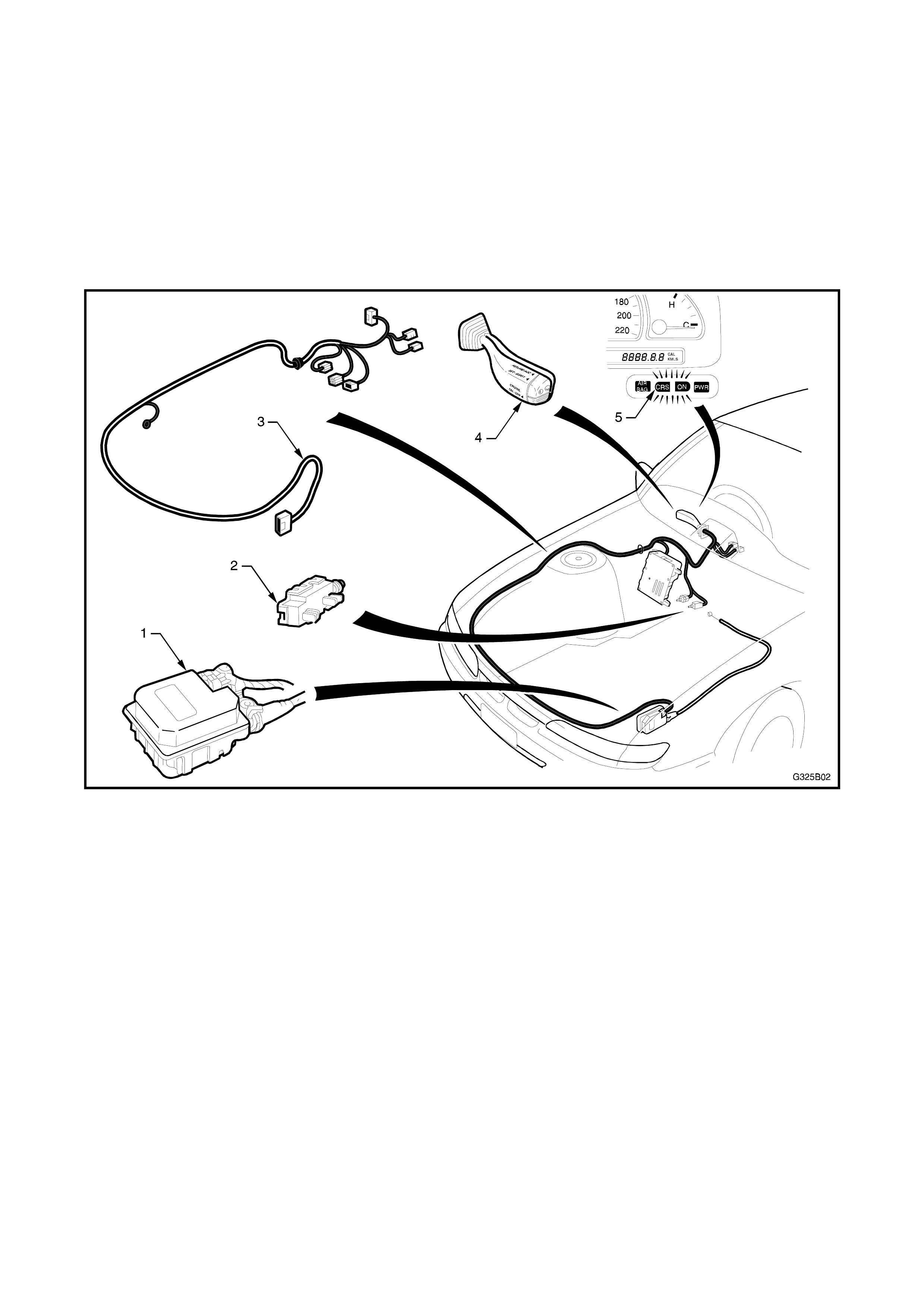
As shown in Fig. 5B-2, the system incorporates an actuator (1), release switch (2), patch wiring harness (3), and
control switch (4) which replaces the original indicator stalk.
Two light globes are added to the instrument cluster for the cruise control ‘on’ and ‘crs’ indicator lamps (5). The
wiring harness is also used to integrate the cruise control system with the existing body control module (BCM)
and interior fuse and relay panel.
Service procedures for the cruise control system are the same as the factory fitted cruise control system.
Refer to Section 12E, CRUISE CONTROL SYSTEM in Volume 6 of the VR Service Information.
Figure 5B-2
3. POWER ANTENNA
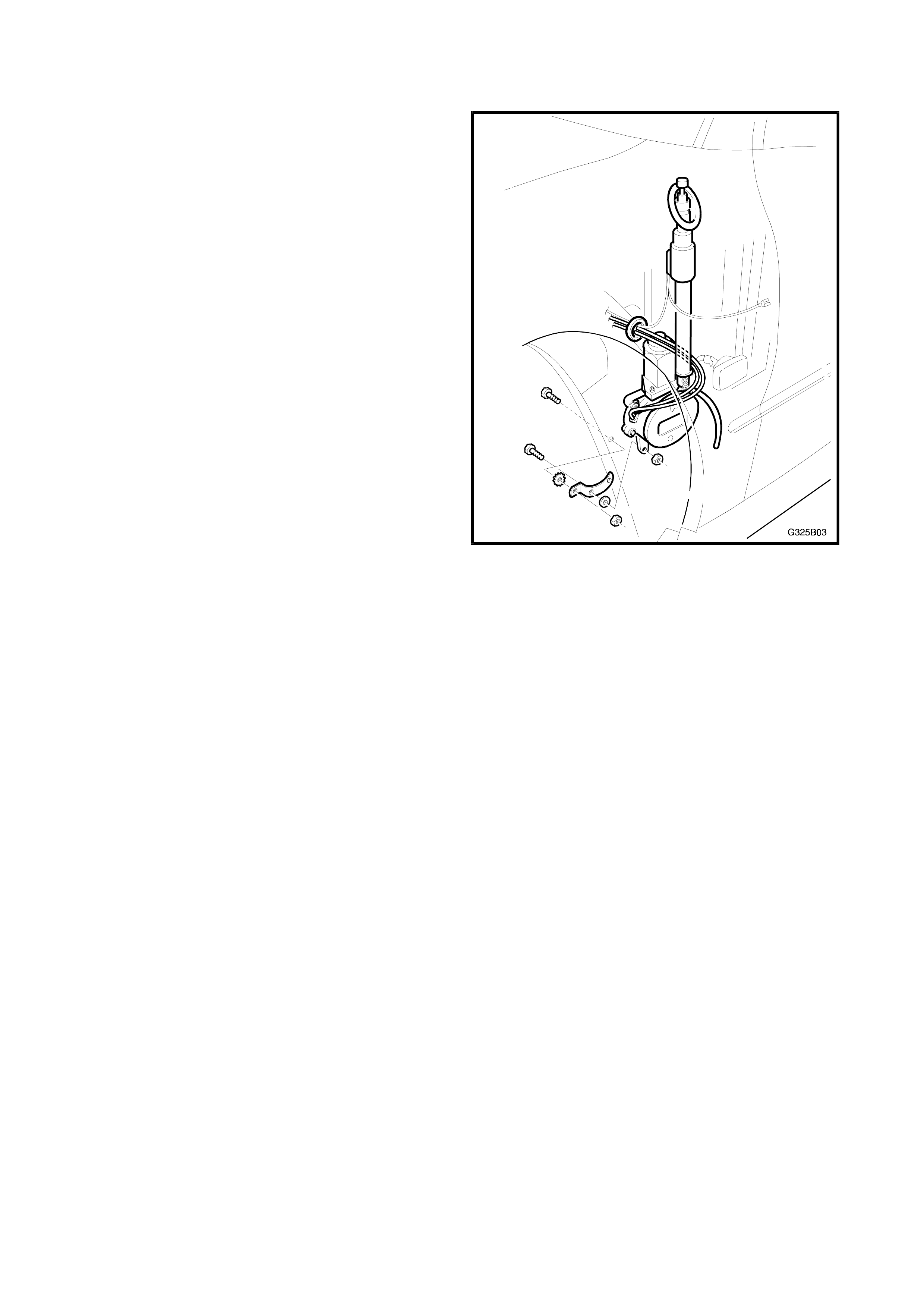
The Holden By Design power antenna is controlled by
a control module which is mounted behind the
glovebox. A patch harness is connected between the
power antenna, control module and radio unit. The
mounting of the power antenna as shown is the same
as the factory fitted unit.
For service procedures for the Holden By Design
power antenna, refer to Section 12D, RADIO &
CASSETTE PLAYER in Volume 6 of the VR Series
Service Information.
Figure 5B-3
4. COUNTRY ROO BAR
The Holden By Design country roo bar is mounted to
a square section bar mount which is attached to the
vehicle via chassis mounts. The chassis mounts are
attached to each front longitudinal with the front
bumper support bracket bolts.
REMOVE
1. From each side, remove the struts attaching the
rear of the bumper facia to the support beam
bracket.
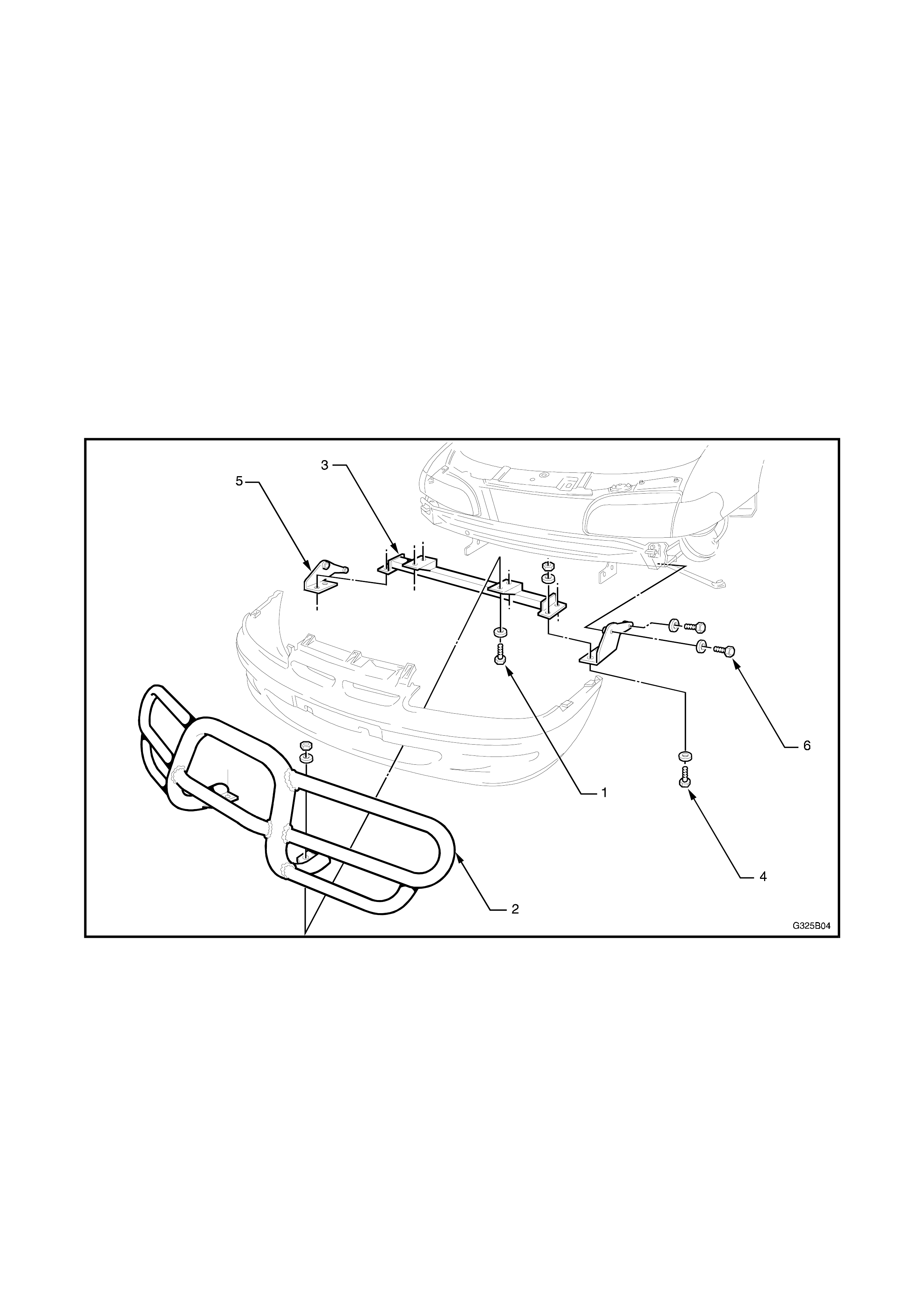
2. From underneath the bumper facia, remove the
four bolts, nuts and washers (1) attaching the
country roo bar (2) to the bar mount (3).
NOTE: Have an assis tant support the country roo bar
while performing this operation.
3. Remove the country roo bar by caref ully guiding it
through the bumper facia air intake opening.
Figure 5B-4
4. If required, remove the bar mount by removing
the four bolts nuts and washers (4) attaching the
bar mount to each chassis mount (5).
NOTE: The bar mount can be removed with the
bumper facia in situ by removing one chassis mount
and flexing the lower edge of the f ac ia to allow the bar
mount through.
5. If required, remove the chassis mounts by
removing the two bolts (6) attaching the chassis
mount and bumper support beam bracket.
INSTALL
NOTE: While it is easier to f it the chas sis m ounts and
bar mount to the vehicle prior to fitting the bumper
facia, it can also be accomplished with the bumper
facia in situ as described.
1. Fit one chassis mount to the support beam
bracket as shown in Fig. 5B-4, leaving the bolts
finger tight only.
2. Flex the lower edge of the bumper facia and
manoeuvre the bar mount inside the bottom of the
bumper facia so that it sits on top of the chassis
mount.
3. Fit the other chassis mount as described in Step
1.
4. Fit the four bolts, nuts and washers attaching the
bar mount to the chassis mounts.
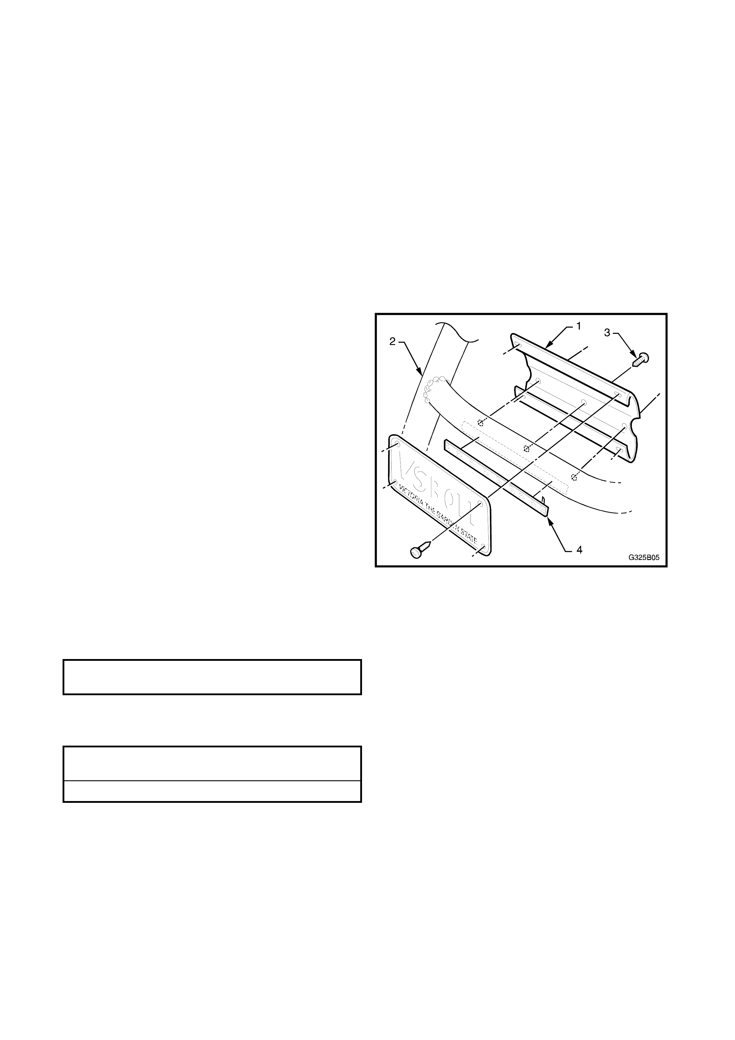
5. If required, fit the number plate holder (1) to the
rear side of the country roo bar (2) with three
attaching screws (3). Place a strip of adhesive
foam tape (4) on the roo bar.
Figure 5B-5
6. With the aid of an assistant, carefully fit the
country roo bar into position, locating the mounts
through the bumper facia air inlet and on to the
top of the bar mount. Tighten the bolts to the
specified torque.
COUNTRY ROO BAR TO
BAR MOUNT BOLT 55 Nm
7. Align the country roo bar with the vehicle.
8. Tighten the remaining bolts to the specified
torque.
BAR MOUNT TO CHASSIS
MOUNT BOLT 55 Nm
CHASSIS MOUNT BOLT 44 Nm