
SECTION 5C – VS SERIES III ID UTILITY & 195 KW V8
ENGINE
CAUTION:
This vehicle may be equipped with a driver’s side only or driver’s and front passenger’s side Air
Bags. An AIR BAG is a Supplemental Restraint System (SRS). Refer to CAUTIONS, Section 12M in
Volume 4 of the VS Series Service Manual, before performing any se rvice operation on or around SRS
components, the steering mechanism or wiring. Failure to follow the CAUTIONS could result in air
bag deployment, resulting in possible personal injury or unnecessary SRS system repairs.
CAUTION:
This v ehicle may be equipped w ith LPG ( Liquefied Pet roleum Gas). In th e interests of safet y, the LPG
fuel system should be isolated by turning 'OFF' the manual service valve and then draining the LPG
service lines, before any service work is carried out on the vehicle. Refer to the LPG leaflet included
with the Owner's Handbook for details or Volume 6 of the VS Series Service Manual for more specific
servicing information.
1. GENERAL INFORMATION
This Section of the Holden By Design Service Information Supplement provides a detailed summary of the VS
Series III utility id enhancement package and associated components, including the 195 kW engine.
The utility id enhancem ent package c onsists of components designed to enhance and add spor ting character to
the Holden utility. The standard package consists of a unique single opening grille, f ive spoke alloy wheels and
revised suspension.
Where the id enhancement package is optioned on a standard model utility, the bumper bars are painted the
vehicle body colour. A Holden By Design identification plate, decals and id badging complete the package.
In addition, other components can be added or optioned individually to further enhance the vehicle.
The components include:
• Rigid tonneau,
• Cargo liner,
• 195 kW V8 engine,
• Alloy wheels of a different style.
The 195 kW V8 engine was developed by Holden Special Vehicles ( HSV) and incorporates m odifications to the
inlet, exhaust and engine management systems.
Where necessary, the removal and installation procedures for various components of the package have been
included, however for information not contained in this Section, refer to the relevant VS Series Service Manual.
Fig. 5C-1 illustrates the major components available for the VS Series III Utility.
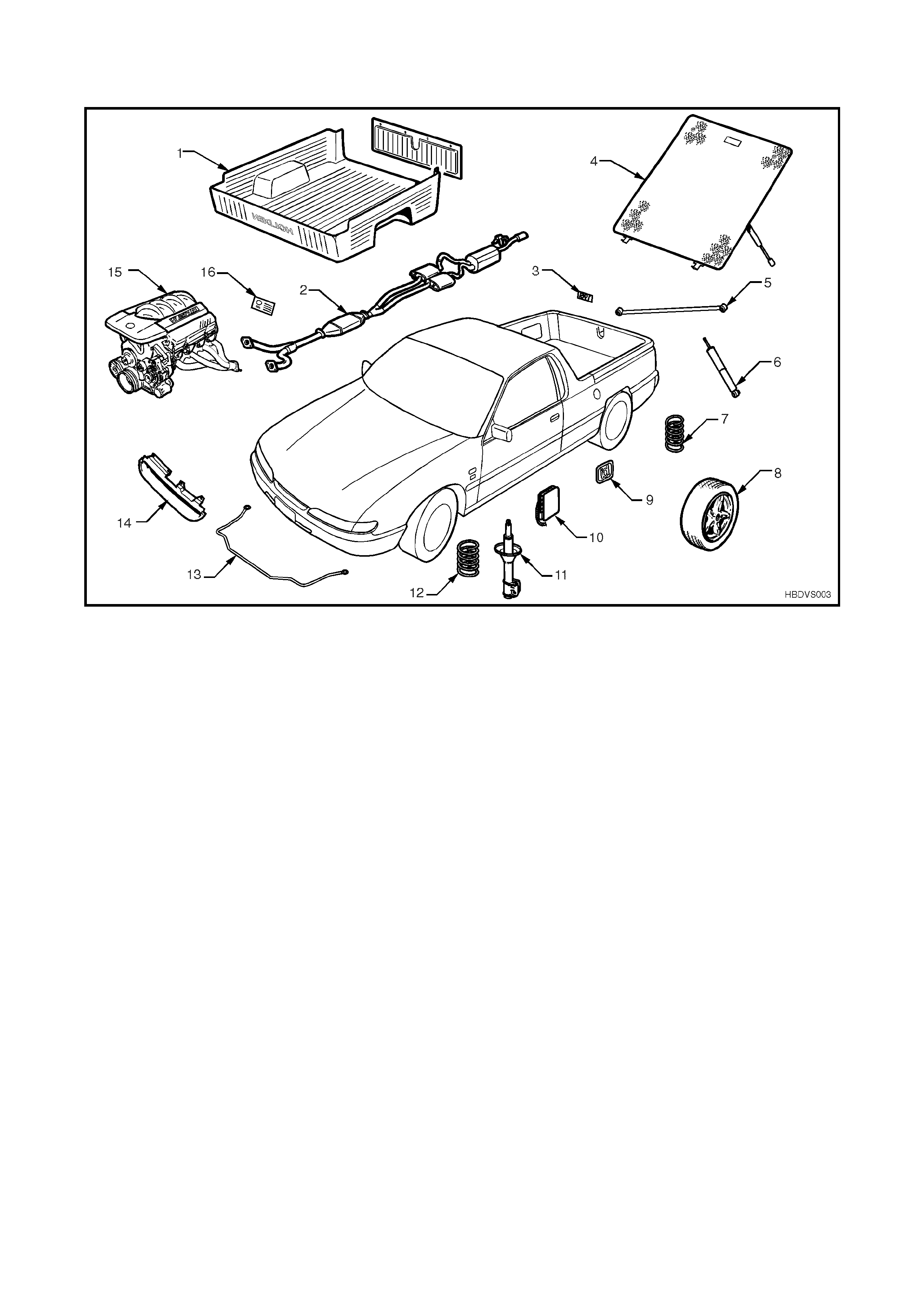
1.1 MAJOR COMPONENTS
Figure 5C-1
1. Cargo liner 7. Rear coil springs 13. Front stabalizer bar
(27mm)
2. Exhaust system 8. Alloy wheels 14. Sports grille
3. 195i emblem 9.id badge 15. 195 kW V8 engine
4. Rigid tonneau 10.PCM 16. HBD identification plate
5. Rear panhard rod 11.Front gas shock absorbers
6. Rear gas shock absorbers 12. Front coil springs

2. ID SPORTS GRILLE
The sports grille fitted to VS Series III Utility Models with the id enhancement package remains unchanged from
earlier VS Utility Model. For all id sports grille information, including removal and installation procedures, refer to
Section 5A VS ID UTILITY in this Service Information Supplement.

3. RIGID TONNEAU
The rigid tonneau cover fitted to VS Series III Utility Models with the id enhancement package remains
unchanged from earlier VS Utility Model. For the removal and installation procedures of the rigid tonneau cover,
refer to Section 5A VS ID UTILITY in this Service Information Supplement.

4. CARGO LINER
The cargo liner fitted to VS Series III Utility Models with the id enhancement package remains unchanged from
earlier VS Utility Model. For the removal and installation procedures of the rigid tonneau cover, refer to Section
5A VS ID UTILITY in this Service Information Supplement.
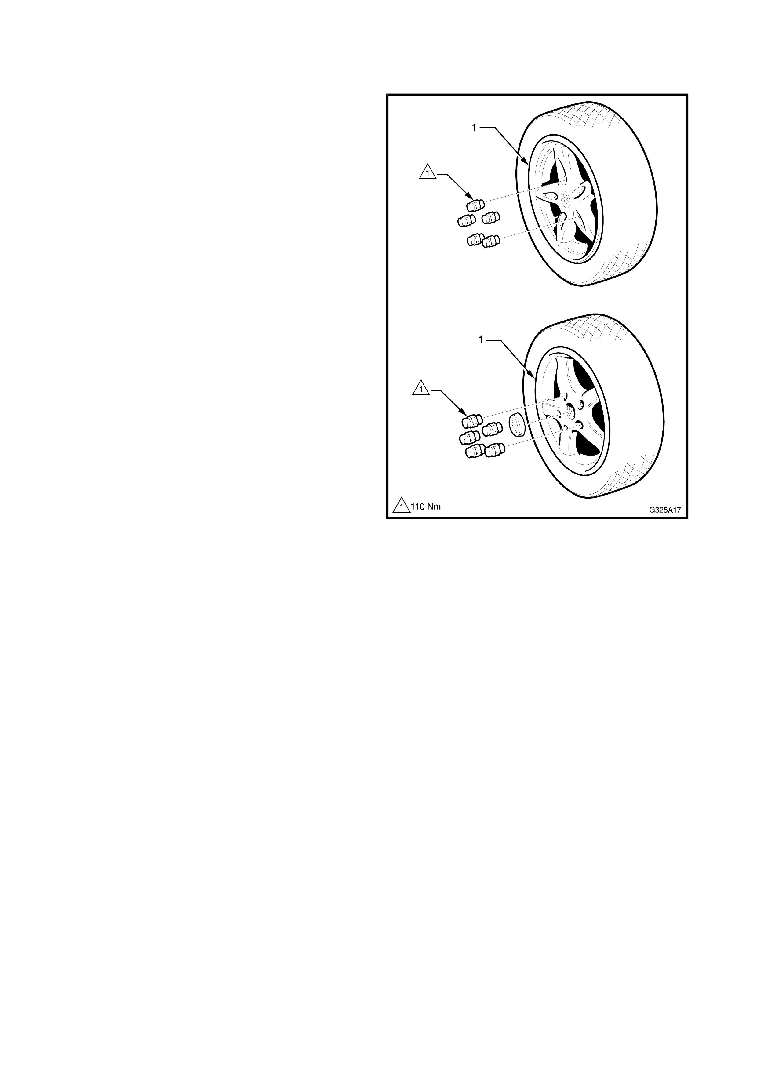
5. ALLOY WHEELS
Two alloy wheel styles are available for Holden By
Design VS Utility Vehicles. Both have a 16” diameter
and are 7” wide.
While wheel nuts designed for use with alloy wheels
are fitted, the wheel studs remain the same as
standard VS Series Vehicles.
The standard spare wheel is not changed and as
such, should be used as a temporary wheel only.
This Section of the Holden By Design Service
Supplement illustrates the wheel types only. For the
information required to service wheels for VS Series
Vehicles, refer to Section 10, WHEELS & TYRES in
Volume 4 of the VS Series Service Information.
Figure 5C-2
6. SUSPENSION
To cater for the increased power and enhance the
overall performance of the vehicle, the suspension has
been revised to include:
• HBD developed progressive rate springs
• HBD recalibrated gas shock absorbers
• HBD developed front stabiliser bar
• HBD developed rear panhard rod
These changes do not effect the Service Operations of
the vehicle, however, specifications have been revised
and published in this Section.
Whenever any Service Operation is performed on the
front or rear suspension of a VS Series III Utility Model
with Production Option XX3, refer to Sections 3 FRONT
SUSPENSION and 4A FIVE LINK REAR SUSPENSION
in the relevant Volumes of the VS and VR Series
Service, while referring to the following specifications.
6.1 SPECIFICATIONS
FRONT
Stabiliser bar
Type......................................................................... Decoupled
Diameter.................................................................. 27.0 mm
Control arm
Type......................................................................... Forged with rubber bushes for attachment to front
crossmember and tension rod. Ball joint is riveted
on to the control arm.
Front wheel bearings
Type......................................................................... Double row ball bearing
Lubricant.................................................................. Sealed for life: non-adjustable
Front strut
Type......................................................................... Oil; gassed – non-serviceable
Piston Diameter....................................................... 30 mm
Capacity................................................................... 310 ml
Front spring details
Model:........................ VS Series III with P.O. XX3
Total number coils:.... 5.70
Free length: ............... 348 mm
Outside diameter:...... 165 mm
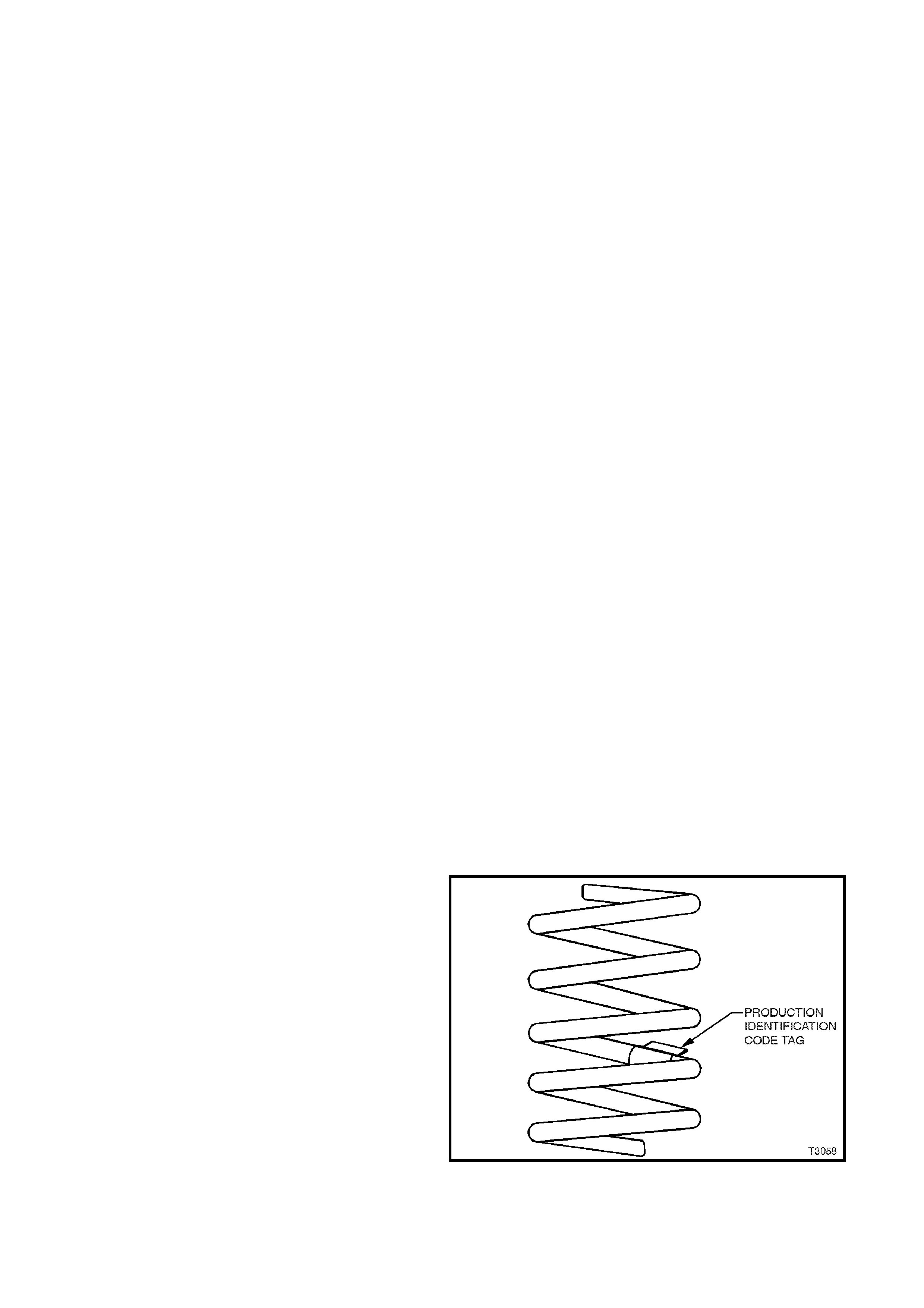
Production I.D. code:. HT
Spring rate & type:..... Variable 25 – 25 N/mm
(3825 ± 110 N @ 194mm)
Figure 5C-3
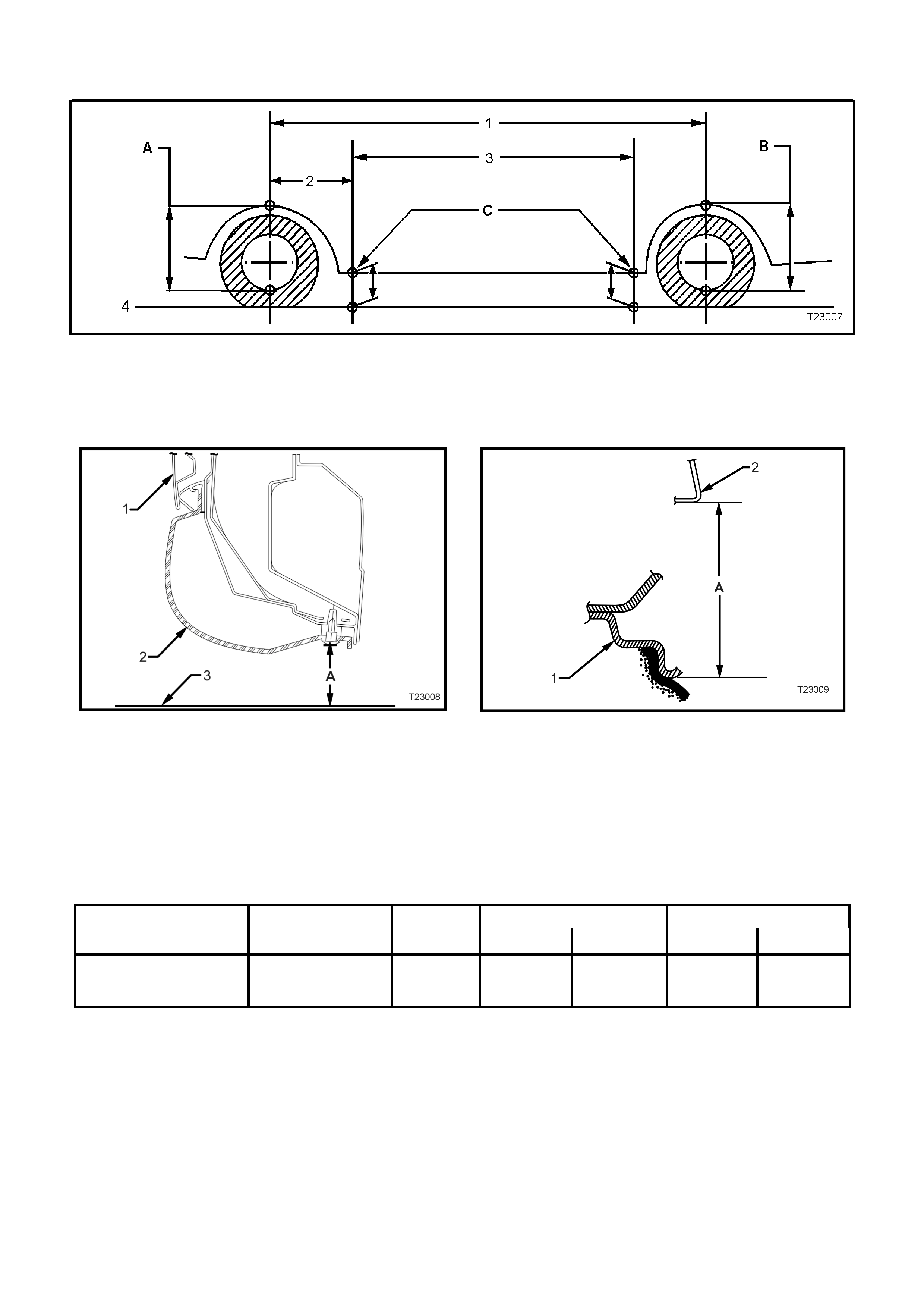
Trim and suspension heights
Figure 3-4
A Front Suspension Height
B Rear Suspension Height
C Trim Height Checking Locations
1. Wheelbase: 2822 mm
2. Reference Point: – 521.25 mm
3. Trim Height Spacing:1800.00 mm
4. Ground Line
Figure 3-5 Rear trim height checking location
(similar location for front)
1. Door
A Trim height
2. Trim
3. Ground line
Figure 3-6 Front and rear suspension checking location
1. Wheel rim
A Suspension height
2. Fender opening
NOTE: The following suspension/trim height dimensions are intended for reference and are intended to
be a guide only (Refer to 2.2 SUSPENSION AND TRIM HEIGHT CHECK, in Section 3 FRONT
SUSPENSION, in Volume 11A of the VR Series Service Information).
SUSPENSION HEIGHT TRIM HEIGHT
VEHICLE
DESCRIPTION TRANSMISSION MODEL FRONT REAR FRONT REAR
VS SERIES III UTILITY
WITH P.O. XX3 Manual or
Automatic Base 610 mm 610 mm 259 mm 298 mm
REAR
Stabilizer bar details
Diameter..................................................................... 16.0 mm
Production I.D. code................................................... AE
Rear spring details
Total number of coils.................................................. 9.06
Free length................................................................. 350 mm (Note: 10mm ring space fitted to RHS)
Inside diameter........................................................... 94.0 mm
Production I.D. code................................................... YA
Spring type & rate....................................................... Variable 49 - 64.1 N/mm

7. 195 KW V8 ENGINE
This Section of the Holden By Design Service Information Supplement describes the components employed in
the 195 kW V8 engine upgrade (Production Option XX3).
Holden Special Vehicles have developed the 195 kW V8 engine, based on the standard Holden 5.0 litre V8
engine. Modified components fitted to this engine, that differ from the standard V8 engine include:
• Cylinder head
• Exhaust valve spring
• Stainless steel valve spring seat
• Exhaust valve
• Fuel rail and throttle body cover (engine dress cover)
• High lift, high duration camshaft (refer specifications in this Section)
• Timing chain and steel sprockets
• Timing chain damper
These modifications are designed to improve the engines breathing and ensure it copes with the power increase.
Accompanying these modified engine components are; a revised air inlet system, a new exhaust system and a
recalibrated powertrain management system (PROM).
Together, these modifications increase the power output to 195 kW @ 4800 rpm and torque output to 430 Nm
@ 3600 rpm.
195 kW V8 engines are identified by the engine option code LB9 & XX3, which is stamped into the vehicle
identification plate. Also, the engine number is prefixed by the letters VN. The engine number is located on the
LH side of the cylinder block above the oil pump housing.
A Holden By Design identification plate and 195i badging completes the package, which is described in 8,
IDENTIFICATION & BADGING in this Section.
All other service procedures for the Holden By Design 195 kW V8 engine are the same as the standard 5.0 litre
V8 engine components. Refer to the relevant Section in Volume 11 of the VS Series Service Information, noting
the following:
Some references in Volume 11 of the VS Series Service manual will refer the reader to Section 6A2 ENGINE
MECHANICAL – V8 ENGINE in Volume 2 of the VT Series Service Information.
Fig. 5C-7 illustrates the 195 kW V8 engine major components.
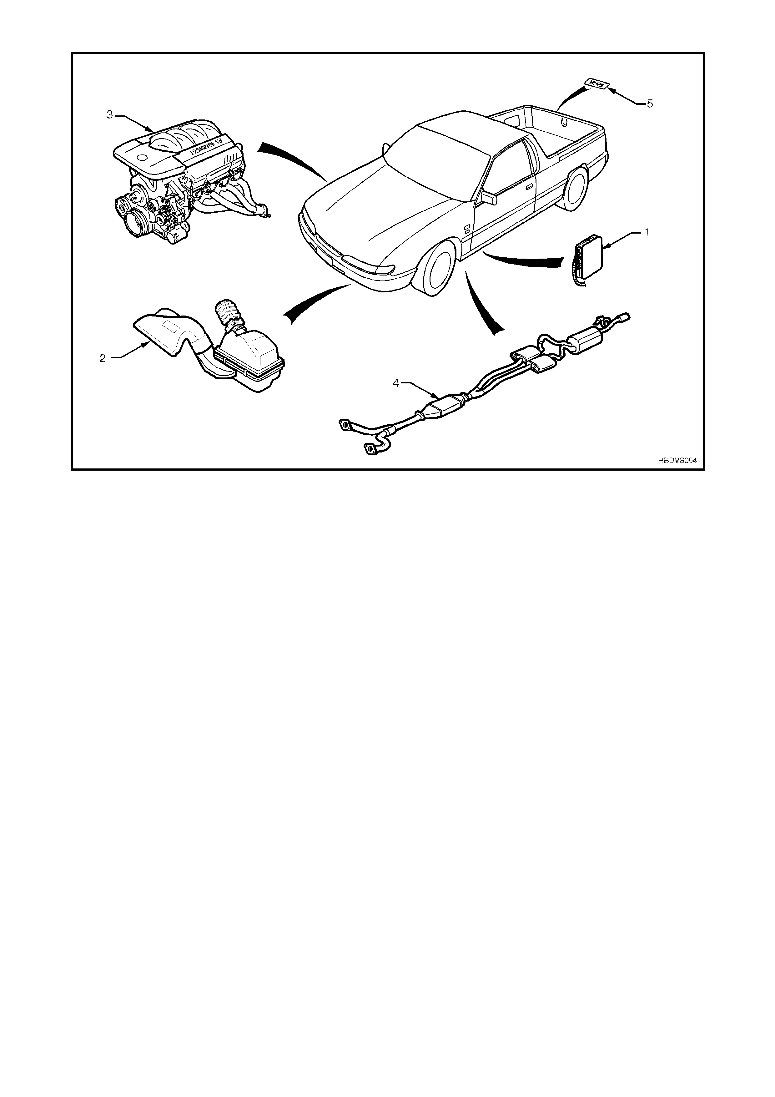
Figure 5C-7
1. Powertrain Control Module (PCM) &
PROM 4. Exhaust system
2. Air inlet assembly 5. 195i emblem
3. 195 kW engine assembly
CAMSHAFT
195 KW V8 CAMSHAFT SPECIFICATIONS
HSV 195 kW V8 camshaft Part No. 06X-970301
Lobe lift 0.28”
Lobe duration: Inlet
Exhaust268°
268°
Valve timing @ 0.050” valve lift:
Inlet open
close
Exhaust open
close
21° BTDC
67° ATDC
65° BTDC
23° ATDC
Duration @ 0.050” 206°
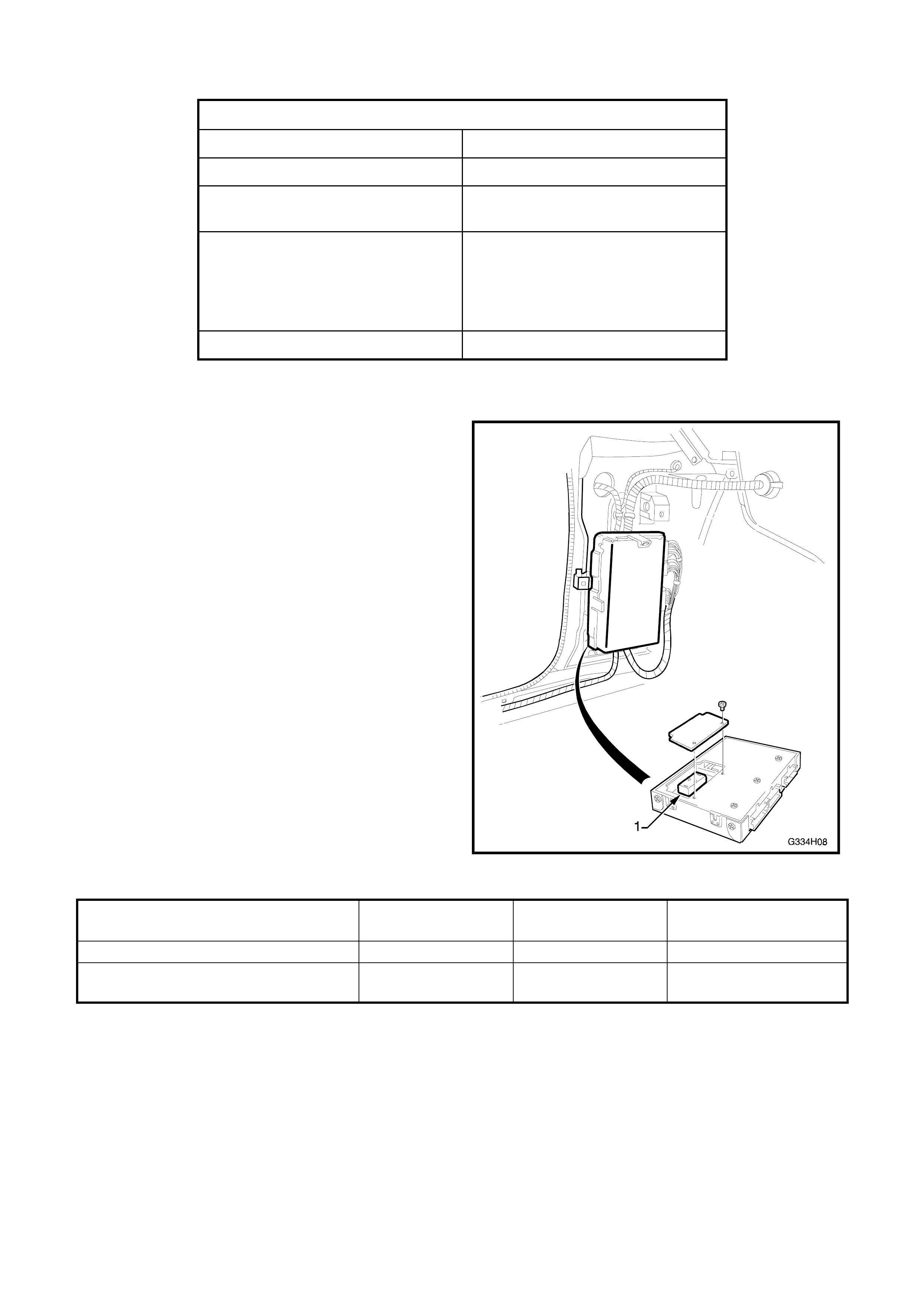
POWERTRAIN MANAGEMENT
Changes to the powertrain management system for
the 195 kW V8 include the fitment of a revised
Powertrain Control Module PROM unit (1).
Service procedures for the Holden By Design 195 kW
V8 powertrain management system are the same as
the standard VS Series V8 powertrain management,
with the exception of the PCM & PROM identifications
as shown in the chart below.
Refer to Section 6C2, POWERTRAIN
MANAGEMENT - V8 ENGINE in Volume 11 of the VS
Series Service Information.
Figure 5C-8
DESCRIPTION HOLDEN PART
No. HSV PART No. BROADCAST CODE
195 kW PROM – Manual transmission 98363158 12F- 990501 CNPC
195 kW PROM – Automatic
transmission 09363168 12F-990502 CNPD
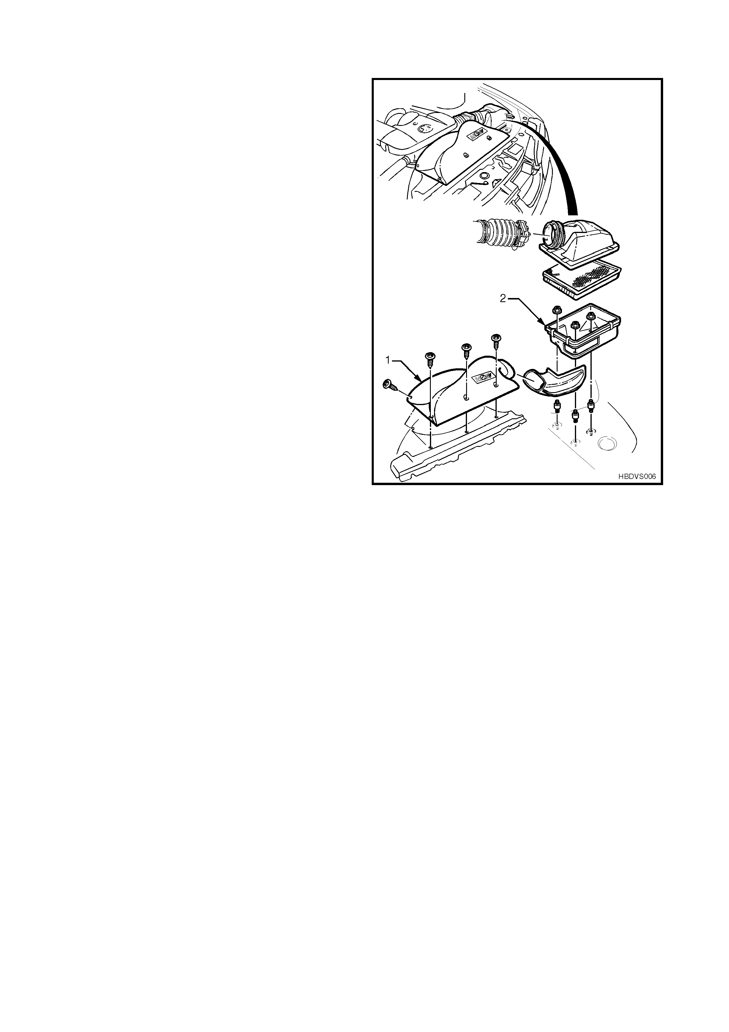
INLET SYSTEM
A newly designed cold-air inlet system, which has
been optimised for the 195 kW engine is fitted.
Changes from the standard air inlet system include a
free flow inlet snorkel (1). All other components,
including the air filter, are standard VS Series III V8
engine (P.O. XT9) components.
Service procedures are the same as the standard V8
engine (with P.O. XT9) inlet system. Refer to Section
6C2, POWERTRAIN MANAGEMENT-V8 ENGINE in
Volume 11 of the VS Series Service Information.
Figure 5C-9
EXHAUST SYSTEM
The Holden By Design 195 kW V8 engine exhaust
system replaces the standard V8 exhaust and is a low
restriction, free flowing design. Although service
procedures are the same as the standard exhaust
system, the clearances differ, which are shown in Fig.
5C-10.
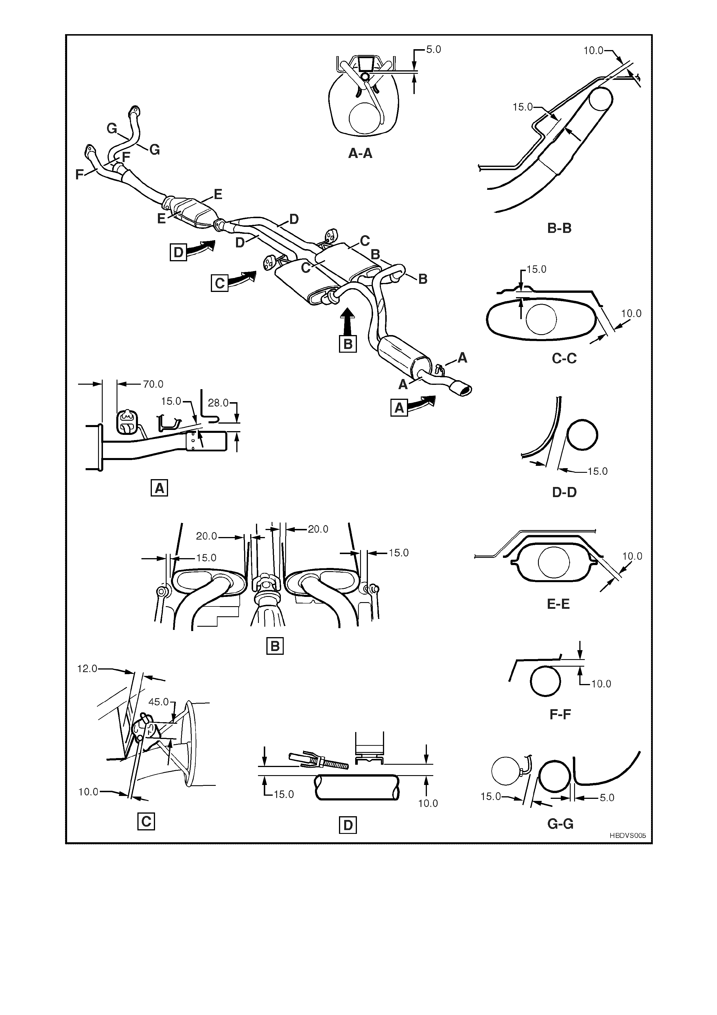
Figure 5C-10
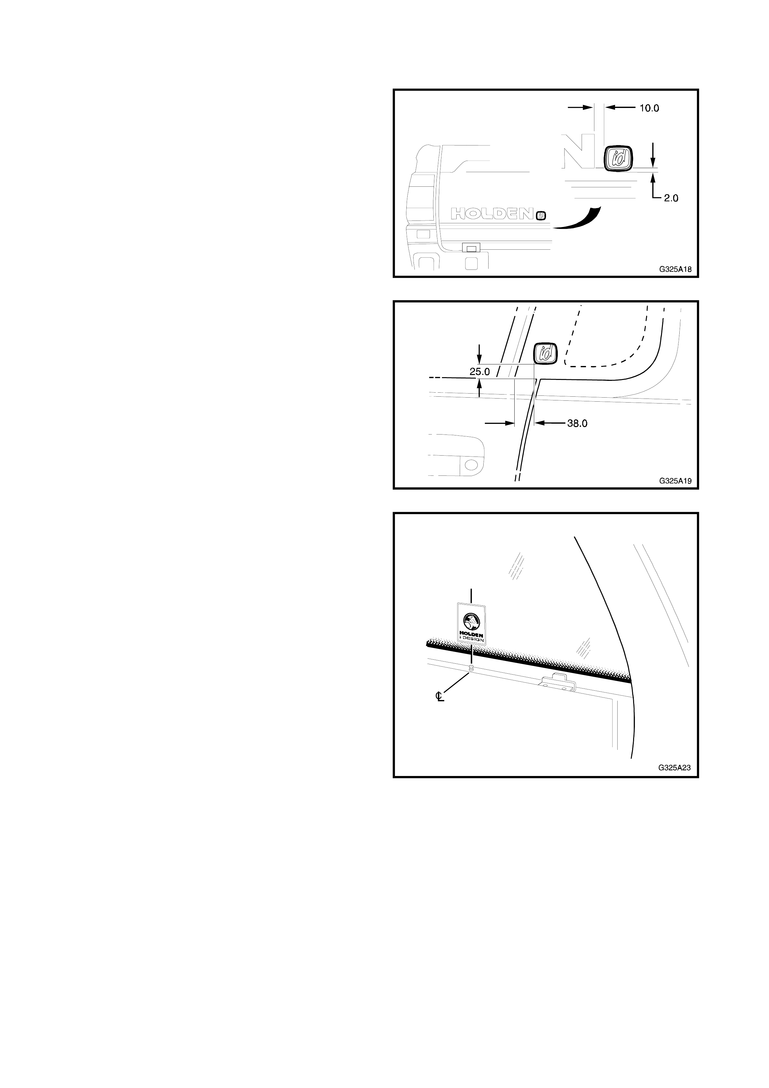
8. IDENTI FICATION & BADGING
All Holden By Design VS Series III id utilities are f itted
with unique id badging which is affixed to the tailgate
and each side quarter glass as shown in Figs. 5C-11
and 5C-12.
Figure 5C-11
Figure 5C-12
A Holden By Design decal is affixed to the rear
window. It is placed just above the edge of the
ceramic band, in line with the third tonneau cover
retainer.
NOTE: Some earlier vehicles had the decal aligned
with the second tonneau cover retainer or rigid
tonneau hinge centre.
Figure 5C-13
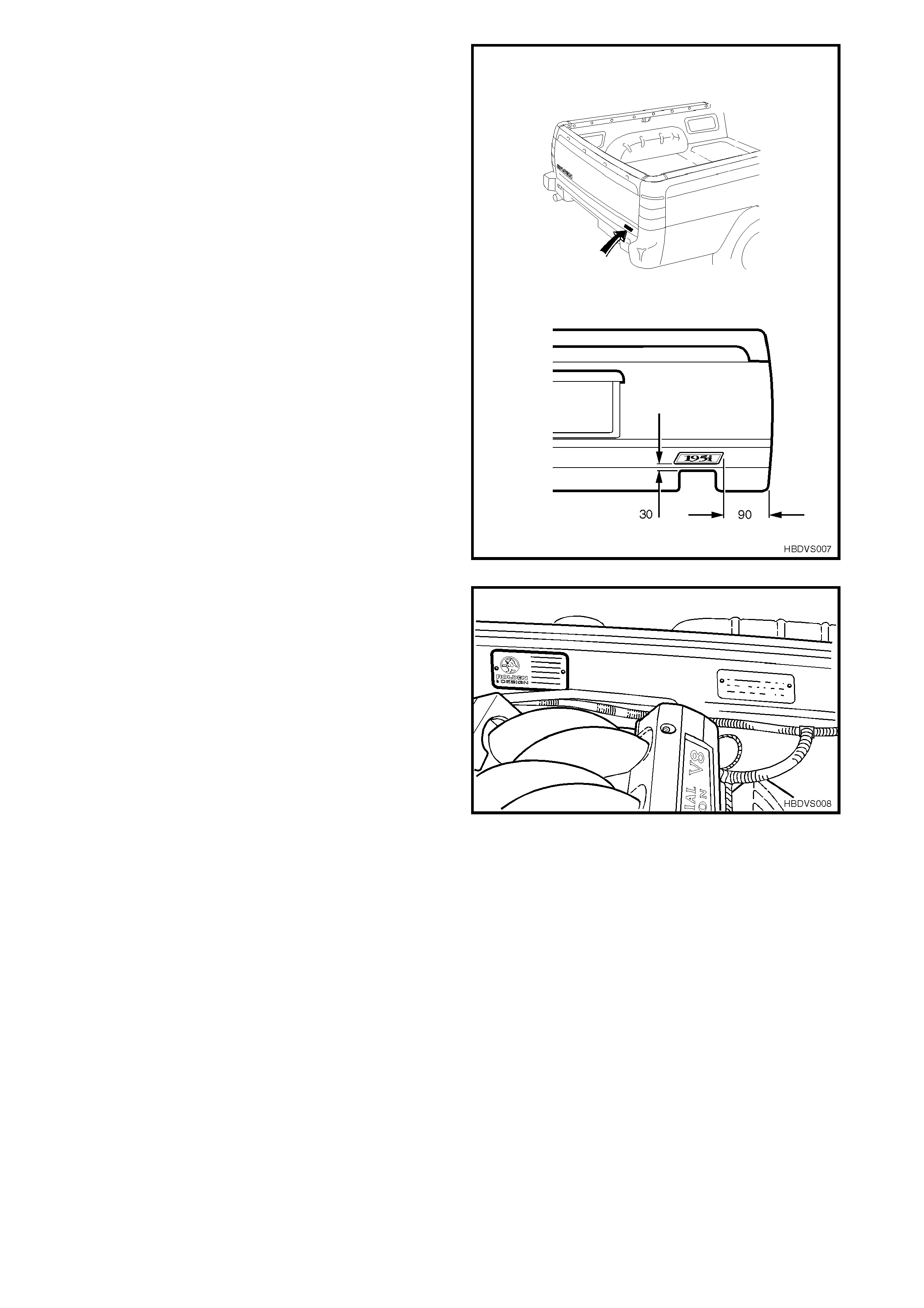
Vehicles fitted with the 195 kW V8 engine, receive a
unique 195i decal, which is affixed to the tailgate as
shown.
Figure 5C-14
A HBD identification plate is installed onto the engine
compartment side of the cockpit module with pop-
rivets.
Figure 5C-15