
SECTION 6A - VS SERIES STATESMAN & CAPRICE
CAUTION:
This vehicle may be equipped with a driver’s side only or driver’s and front passenger’s side Air
Bags. An AIR BAG is a Supplemental Restraint System (SRS). Refer to CAUTIONS, Section 12M in
Volume 4 of the VS Series Service Manual, before performing any service operation on or around SRS
components, the steering mechanism or wiring. Failure to follow the CAUTIONS could result in air
bag deployment, resulting in possible personal injury or unnecessary SRS system repairs.
CAUTION:
This v ehicle may be equipped w ith LPG ( Liquefied Pet roleum Gas). In th e interests of safet y, the LPG
fuel system should be isolated by turning 'OFF' the manual service valve and then draining the LPG
service lines, before any service work is carried out on the vehicle. Refer to the LPG leaflet included
with the Owner's Handbook for details or Volume 6 of the VS Series Service Manual for more specific
servicing information.
1. GENERAL INFORM ATION
This Section of the Holden By Design Service Inf ormation Supplem ent describes the pac kages available f or the
VS Series Statesman & Caprice which consist of:
• Sunroof,
• Level ride,
• LPG,
• Lip spoiler, and
• Alloy wheels.
The Holden By Design sunroof is electrically controlled and f eatures tilt, vent and slide f unctions via a one touch
switch. T he sunr oof panel is cons tr uc ted f rom glas s and a trimmed s unshade is pr ovided. Other f eatur es include
automatic closing of the sunroof when the vehicle is immobilised and anti-jamming protection.
Level ride suspens ion maintains the co rrect ride height when towing or the vehicle is heavily laden. T he Holden
By Design system features electronic control of an air compressor and rear air shock absorber system.
The Holden By Design LPG system f ully integrates with the vehicle’s electric al m ec hanical, engine m anagem ent
and security systems. W here the LPG system is installed, the rear suspension is revised ensuring correct ride
height is maintained and handling is not compromised.
Adding style with subtlety, the Holden By Design lip spoiler and alloy wheels add the finishing touch.
Fig. 6A-1 illustrates the VS Series States man & Capr ice maj or co mponents. F or information not c ontained in this
Section, refer to the relevant VS Series Service Information.
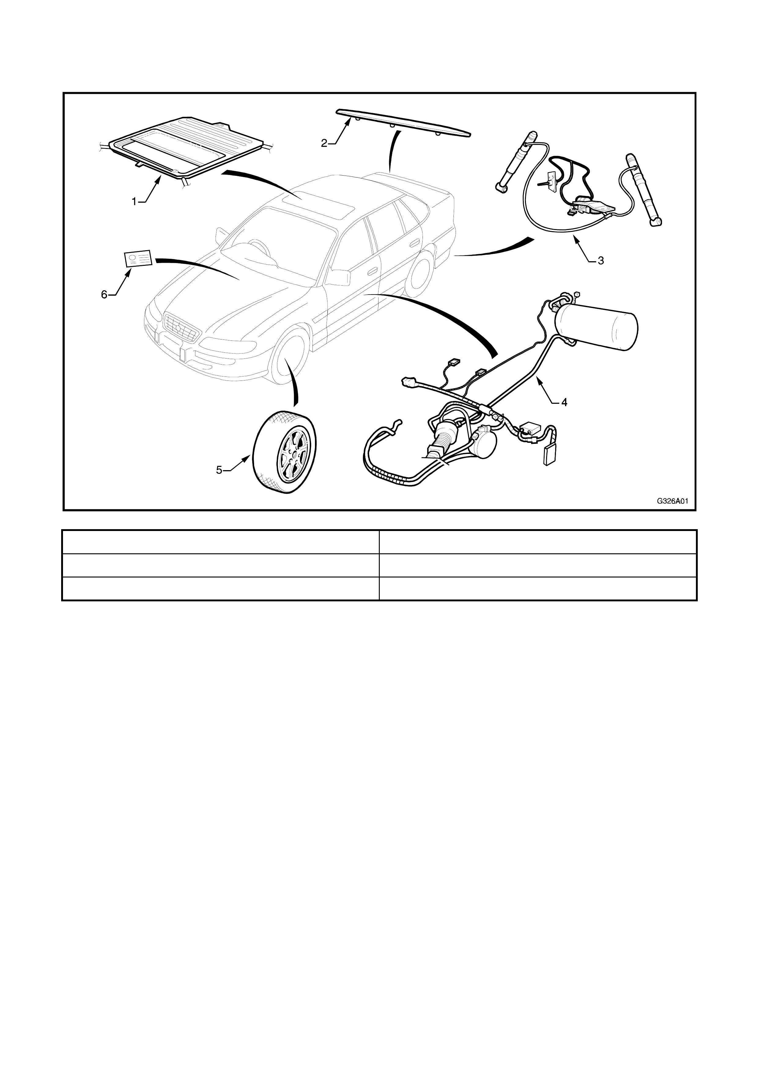
1.1 MAJOR COMPONENTS
Figure 6A-1
1. Sunroof assembly 4. LPG system
2. Lip spoiler 5. Alloy wheel
3. Level ride assembly 6. HBD identification plate
2. SUNROOF
The Holden By Design sunroof an elec tr ically operated, two way sliding and tilting type. It is oper ated by a roc ker
switch, centrally located in the vehicle’s headlining, forward of the sunroof aperture.
For service purposes, the Holden By Design VS Series sunroof is the sam e as the VT Series sunroof, with the
exception of the size and contour of the glass panel etc.
Refer to Section 4C, VT SERIES SUNROOF in this Supplement for further information.
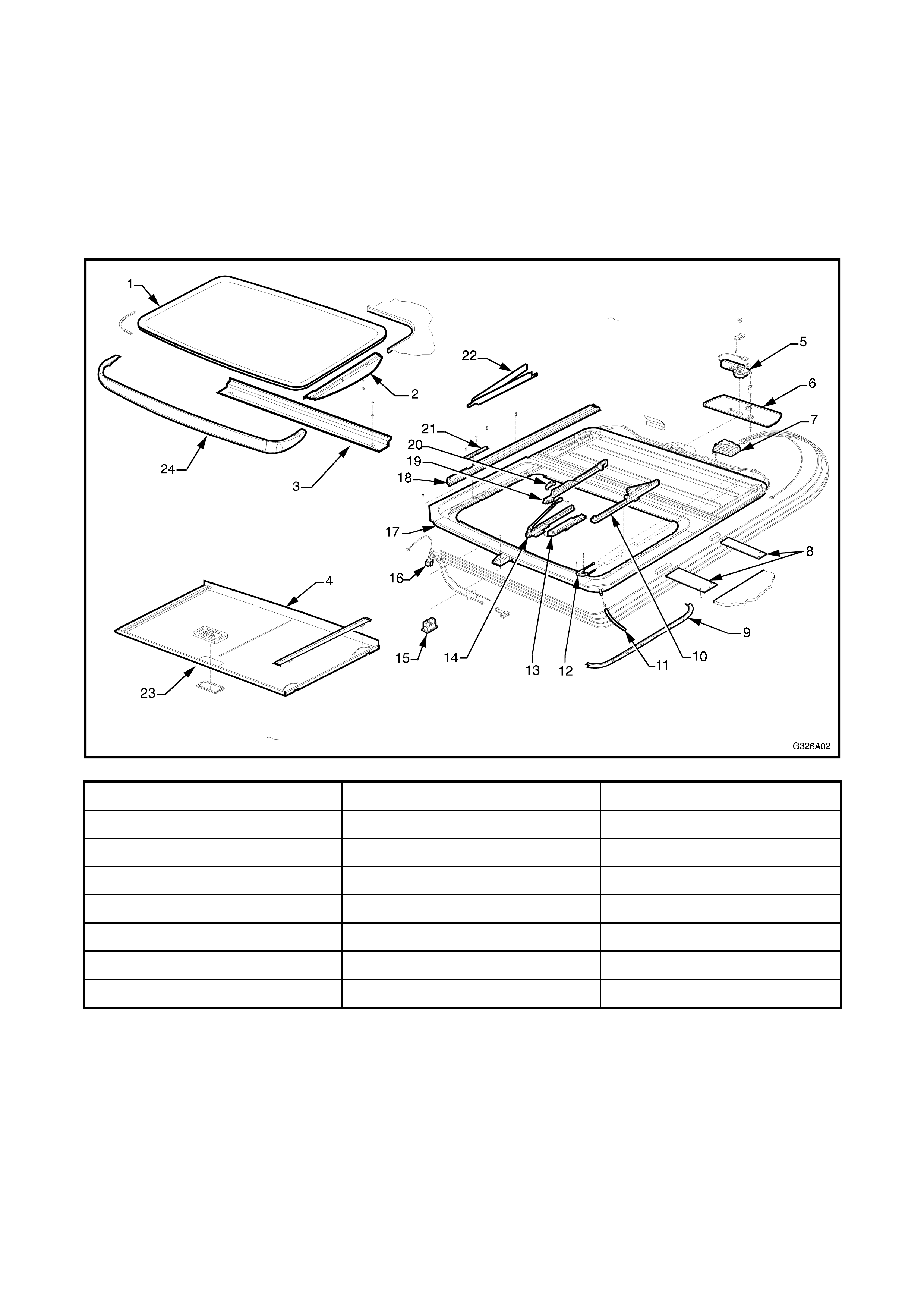
Figure 6A-2 illustrates the Holden By Design sunroof components.
Figure 6A-2
1. Glass Panel 9. Side trimming 17. Frame
2. Exterior cover 10. Rear driving slide 18. Guide rail
3. Drain Channel 11. Drain tube 19. Rear basic slide
4. Sunshade guide 12. Retraction mechanism 20. Blocking catch
5. Drive motor 13. Front driving slide 21. Locator
6. Drive motor cover 14. Front basic slide 22. Mechanism cover
7. Sunroof control unit (SCU) 15. Switch 23. Sunshade
8. Side support bracket 16. Harness 24. Wind deflector

3. LEVEL RIDE
This Section of the Holden By Design Service
Information Supplement describes the level ride
system. For service procedures and a full description
of the level ride operation, refer to Section 4A-2,
INDEPENDENT REAR SUSPENSION in Volume 9 of
the VS Series Service Information.
The Holden By Design level ride suspension is an
electronically controlled system which maintains the
vehicle at a constant height, regardless of load. The
main components of the system are shown in the
following diagrams.
The ride height sensor (1) is attached to the RH
suspension trailing arm (2) via a connecting link (3).
The sensor incorporates an electronic controller
which operates an air compressor or air exhaust
solenoid valve as required according to the position of
the trailing arm after a period of time.
Figure 6A-3
Mounted to the underside of the rear floorpan, the
compressor assembly (1) consists of an air
compressor and air exhaust solenoid valve. An air
filter (2) is clipped into the floor crossmember.
The compressor supplies the required air pressure to
an air bag in each rear superlift air shock absorber via
flexible air lines. This returns the vehicle to within the
specified ride height parameters.
The exhaust solenoid valve is used to vent air from
the air bags, which lowers the vehicle to within the
specified ride height parameters.
All air entering the system passes through the air
filter.
Figure 6A-4
4. LPG
The Holden By Design LPG system for VS Series Statesman & Caprice fully integrates with the vehicle’s
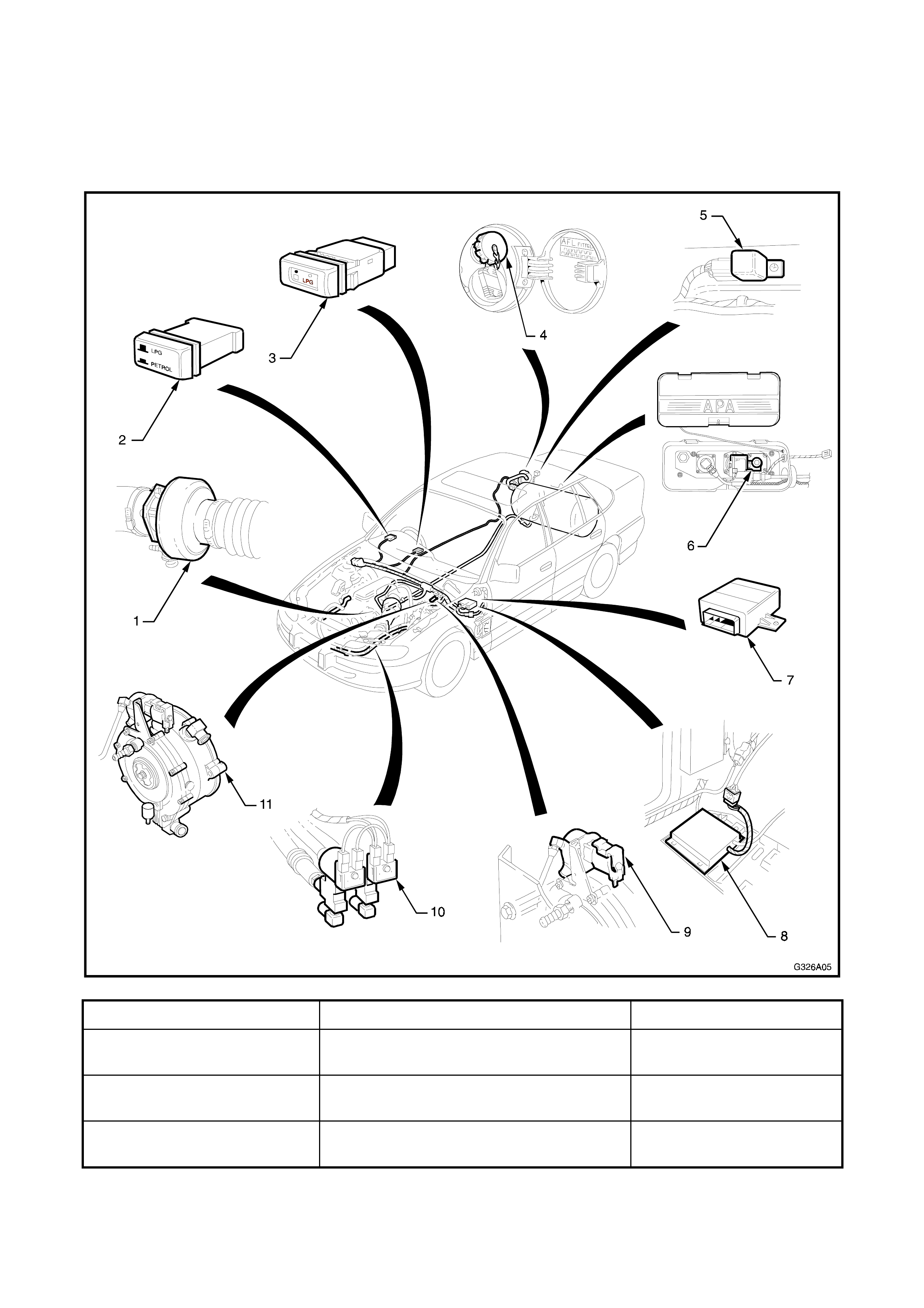
electrical, mechanical, engine management and security systems. Figure 6A-5 illustrates the Holden By Design
LPG system major components.
For all service procedures refer to Volume 6, LPG SYSTEMS in the VS Series Service Information.
Figure 6A-5
1. Mixer 5. Fuel gauge interface relay 9. LPG lockoff
2. Fuel mode switch (early
type) 6. Solenoid & service valve assembly 10. Fuel control valves
3. Fuel mode switch (late
type) 7. Interlock module (late system) 11. Converter
4. LPG filler valve 8. Adaptive digital processor (early
system)
5. LIP SPOILER
The VS Series lip spoiler is painted the vehicle’s body
colour. The painting procedure is relatively straight
forward, providing the correct steps are followed.
Refer to your paint supplier if further information is
required.
REMOVE
1. Open the deck lid and remove the deck lid inner
trim. Refer to Section 1, BODY in Volume 1 of the
VS Series Service Information.
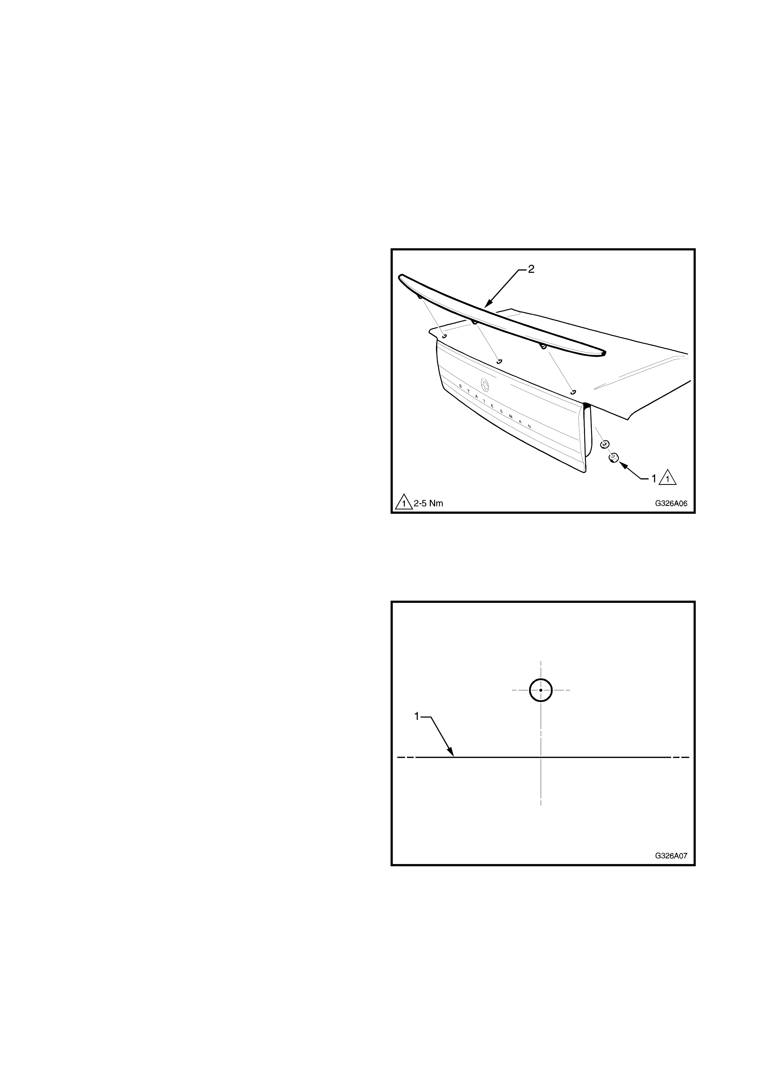
2. From the underside of the deck lid, remove the
three nuts and washers (1) attaching the lip
spoiler (2) to the deck lid.
3. Remove the lip spoiler.
Figure 6A-6
INSTALL
NOTE: If the deck lid has not been replaced, proceed
to Step 7.
1. Construct a drilling template from light card by
photocopying or tracing Fig. 6A-7 for the centre
mount hole.
Figure 6A-7
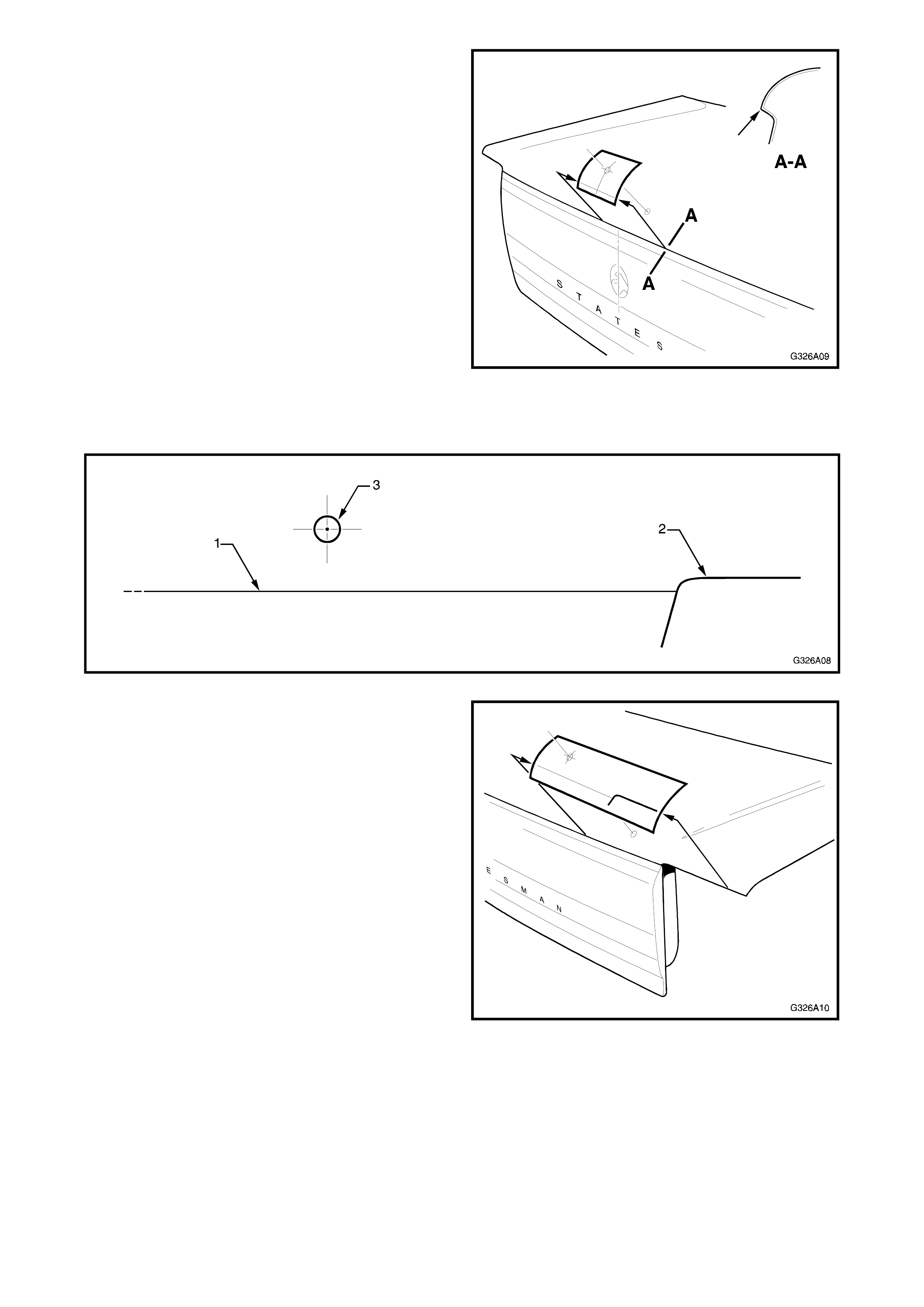
2. Place the centre tem p late on the deck lid, aligning
the line (1) in Fig. 6A-7 with the return lip shown
section
A-A. Align the tem plate centre line with the centre
of the deck lid and mark the centre of the drilling
hole.
Figure 6A-8
3. Construct a drilling template from light card by
photocopying or tracing Fig. 6A-9 for the centre
mount hole.
Figure 6A-9
4. Place the outer template on the RH side of the
deck lid, aligning the line (1) in Fig. 6A-9 with the
return lip and the line (2) with the edge of the
deck lid as shown, ensuring the curvature follows
the edge of the decklid. Mark the centre of the
drilling hole.
Figure 6A-10

5. Turn the template over and repeat Step 2 for the
LH side of the deck lid.
6. Carefully drill the three mount holes, initially with a
6 mm drill bit followed by an 8 m m drill bit. Debur
the holes and apply primer to the bare metal.
7. If required, apply closed cell foam tape to the
underside of the spoiler, around the
circum ference. This acts as a gask et, sealing out
dirt and moisture.
8. Fit the spoiler to the deck lid and fit the washers
and nuts to the studs as shown in Fig. 6A-6. Hand
tighten the nuts.
9. Check the spoiler for correct alignment on the
deck lid and tighten the nuts to the specified
torque.
LIP SPOILER MOUNTING
NUTS 2-5 Nm
9. Refit the deck lid inner trim.

6. ALLOY WHEEL
A uniquely styled 16 x 8” alloy wheel is available for
the Holden By Design VS Series Statesman and
Caprice. When optioned, the wheels are fitted with
P205/50 V-rated tyres. The standard steel rim spare
wheel remains fitted.
This section of the Holden By Design Service
Information Supplement illustrates the wheel type
only. For further service information, refer to Section
10, WHEELS AND TYRES in Volume 4 of the VS
Series Service Information.
Figure 6A-11

7. IDENTI FI CATION
A HBD identification plate is installed onto the dash
panel with pop-rivets.
Figure 6A-12