
SECTION 8A - VX SERIES BODY KIT &
ALLOY WHEELS
1.0 GENERAL INFORM ATION
This Section of the Holden By Design Service Supplement describes the service procedures for the aerodynamic
body styling kit components and alloy wheels available for VX Series vehicles.
The body styling kit consists of:
- Radiator grille insert for Level 1 vehicles,
- Two front aprons; one for Level 1 vehicles and one for Level 2 and Level 3 vehicles, the later requiring a
modification where fog lamps are fitted,
- Unique side skirts,
- Two rear aprons; one for Level 1 vehicles and one for Level 2 and 3 vehicles,
- Three decklid spoilers, Types 1, 2 or 3 depending on customer option and,
- Exhaust extension for Level 2 and 3 vehicles.
A choice of four uniquely styled alloy w heels are available:
- 17” x 8” X-series 8 spoke alloy wheels fitted with 235/45 V-rated tyres,
- 17” x 8” C-series 5 spoke alloy wheels fitted with 235/45 V-rated tyres,
- 17” x 8” RT-series 5 spoke alloy wheels fitted with 235/45 V-rated tyres,
- 16” x 7.5” T-series multi spoke alloy wheels fitted with 225/50 V-rated tyres.
W hen a complete package is fitted, a Holden By Design identification plate and decals are included as part of the
package.
NOTE: Vehicles can be supplied with only one or several of the components. In this case no Holden By Design
badging is included.
Figure 8A- 1 illustrates the VX Series body kit maj or com ponents and alloy wheels. For inform ation not contained in
this Section, refer to Section 1 BODY in the VX Series Service Information.
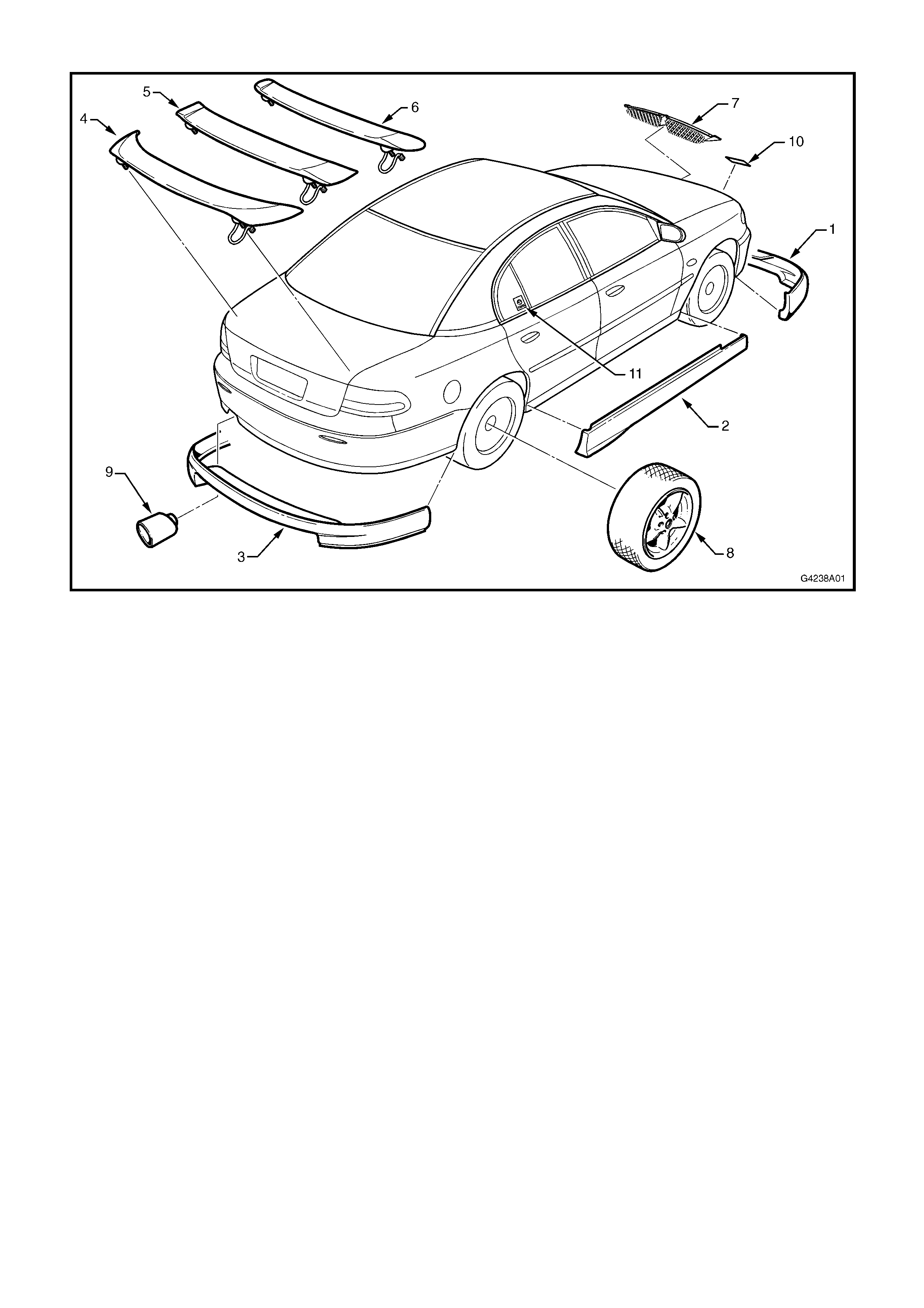
1.1 MAJOR COMPONENTS
Figure 8A-1
Legend
1. Front apron - Level 1 / Level 2 & 3 8. Alloy Wheel: - 17” x 8” X-series 8 spoke
2. Side skirt - 17” x 8” C-series 5 spoke
3. Rear apron - Level 1 / Level 2 & 3 - 17” x 8” RT-series 5 spoke
4. Type 3 rear spoiler - 16” x 7.5” T-series multi spoke
5. Type 2 rear spoiler 9. Exhaust extension - Level 2 & 3
6. Type 1 rear spoiler 10. Holden By Design plate
7. Radiator grille insert - Level 1 11. Holden By Design Label
2.0 RADIATOR GRILLE INSERT
The radiator grille insert replaces the standard Level one VX Series twin grille inserts. If the front bumper
facia is being replaced, the new facia will require modifying to accommodate the grille insert. Refer to
Section 1D, BUMPER BARS in the VX Series Service Information for the bumper facia removal procedure.
NOTE: The radiator grille insert is painted in the vehicle’s body colour. The painting procedures are relatively
straight f orward, pr oviding the cor r ect s teps are followed for PUR polyurethane. Refer to your paint manuf ac turer for
further information.
REMOVE
1. Remove the front bumper facia, refer
Section 1D BUMPER BARS in the VX Series
Service Information.
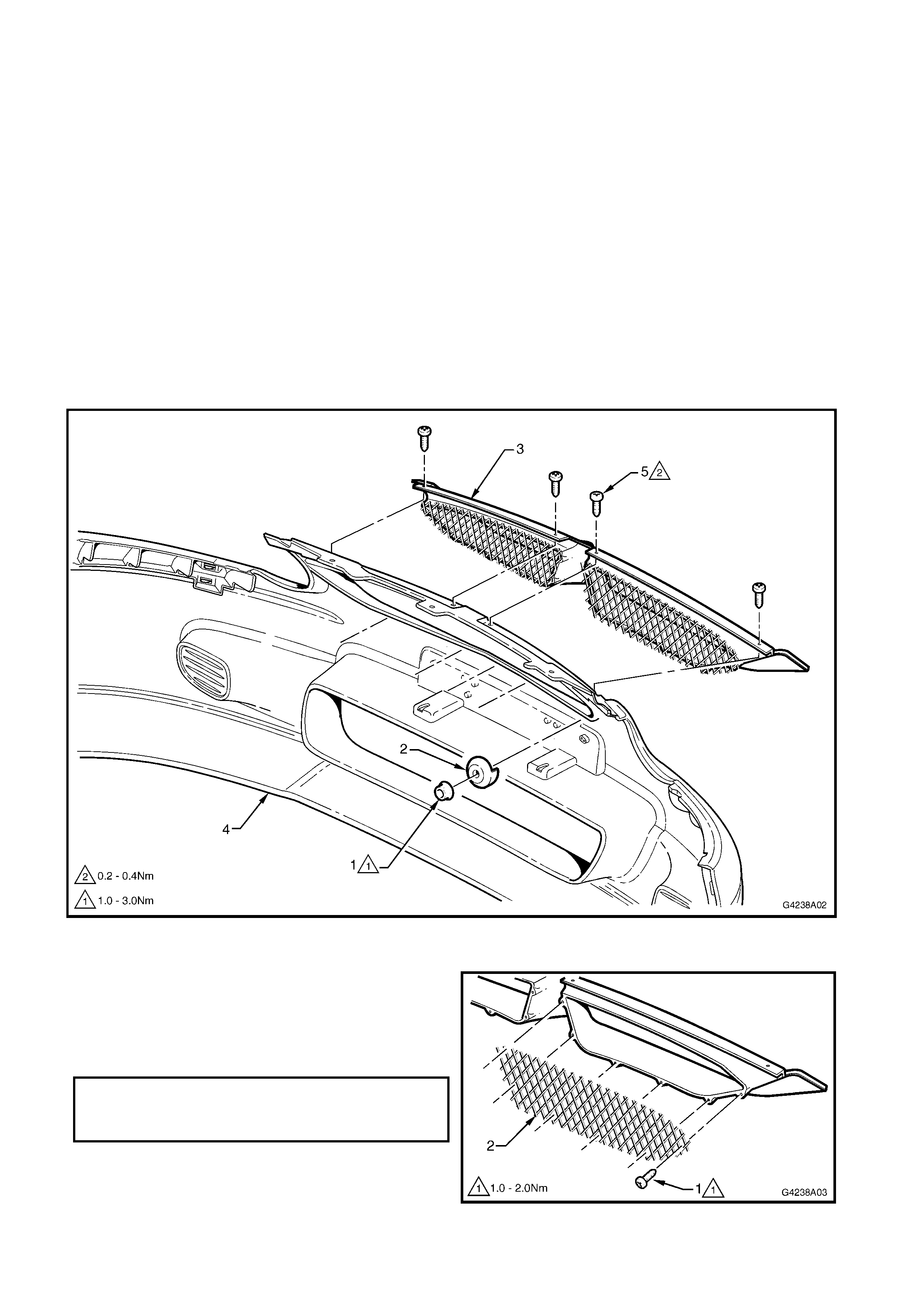
2. Remove the f ive nuts (1) and spacers (2) securing
the grille insert (3) to the bumper facia (4), refer
Fig. 8A-2.
3. Remove the four screws (5) securing the grille
insert to the bumper facia.
4. Remove the grille insert.
Figure 8A-2
DISASSEMBLE
1. Remove the screw (1) 6 places, attaching the
radiator grille insert mesh (2) to the grille insert.
2. Installation is the reverse of remove. Tighten the
screws to the specified torque.
Figure 8A-3
RADIATOR GRILLE INSERT
MESH ATTACHING SCREW 1.0 – 2.0Nm
TORQUE SPECIFICATION
INSTALL
1. If the existing bum per facia is being used, proceed
to step 15.
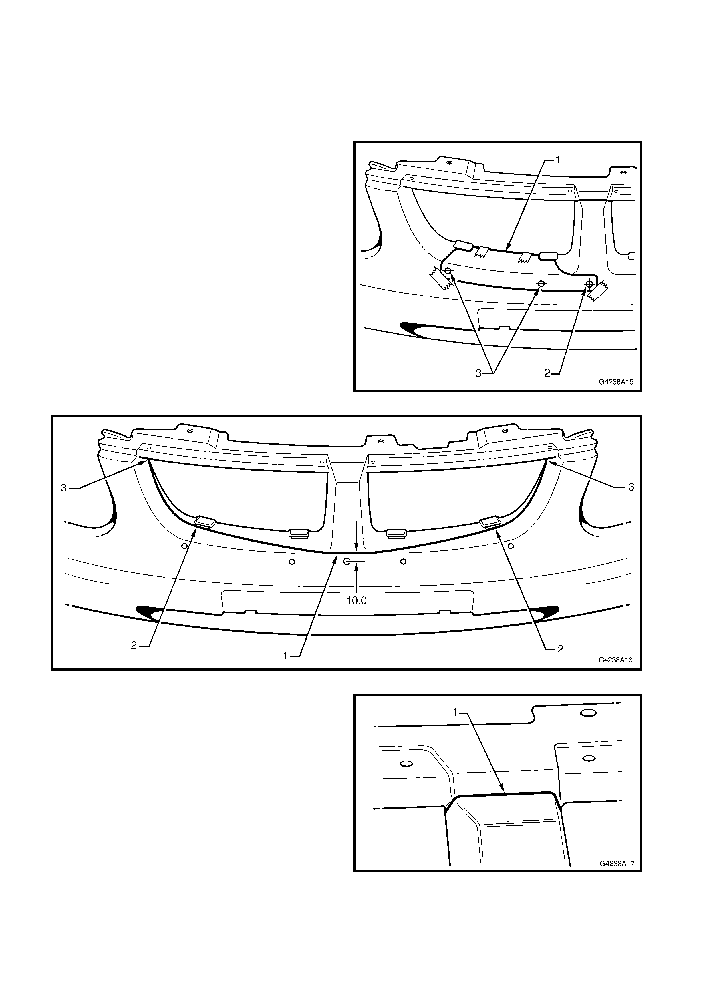
2. Print the template provided in Fig. 8A-8.
NOTE: Ensure the template prints the correct size by
comparing the scale.
3. Cut out the template and attach it to the bumper
facia with tape as shown (1).
4. Pin-punc h the centre of the grille insert centre hole
(2) and the outer holes (3).
5. Carefully remove the template, turn it over and
attach it to the the opposite side. The centre hole
should align with the punch mark.
6. Pin-punch the two outer holes and remove the
template.
7. Drill the five punch marks with a 6 mm drill.
8. Mar k a horizontal line (1), 10 m m above the centr e
of the middle hole, refer Fig. 8A-5.
9. Continue each end of the line directly to the outer
grille insert slots (2).
10. Continue each end of the line to the upper corner
at the rear edge (3).
Figure 8A-4
Figure 8A-5
11. Mark a horizontal line (1) across the recess at the
top of the centre section of the facia.
12. Contiue each end of the line downward at an angle
and rearward.
Figure 8A-6
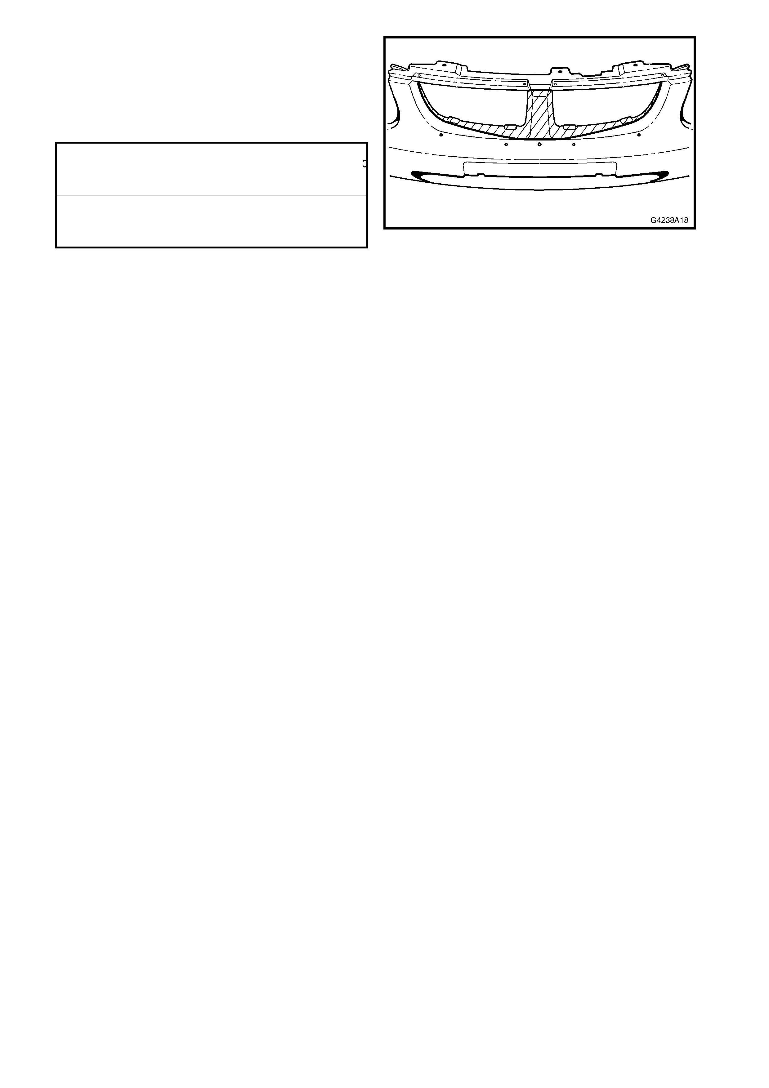
13. Cut the section from the bumper facia.
14. Test fit the grille insert. Adjust the holes as
required.
15. Fit the grille insert, install the four upper screws
and carefully tighten to the specified torque, refer
Fig. 8A-2.
16. Fit a spacer and nut to each of the lower studs.
17. Beginning with the middle nut, tighten the nuts to
the specified torque.
Figure 8A-7
RADIATOR GRILLE INSERT
ATTACHING SCREW 0.2 – 0.4Nm
TORQUE SPECIFICATION
RADIATOR GRILLE INSERT
ATTACHING ATTACHING NUT 1.0 – 3.0Nm
TORQUE SPECIFICATION
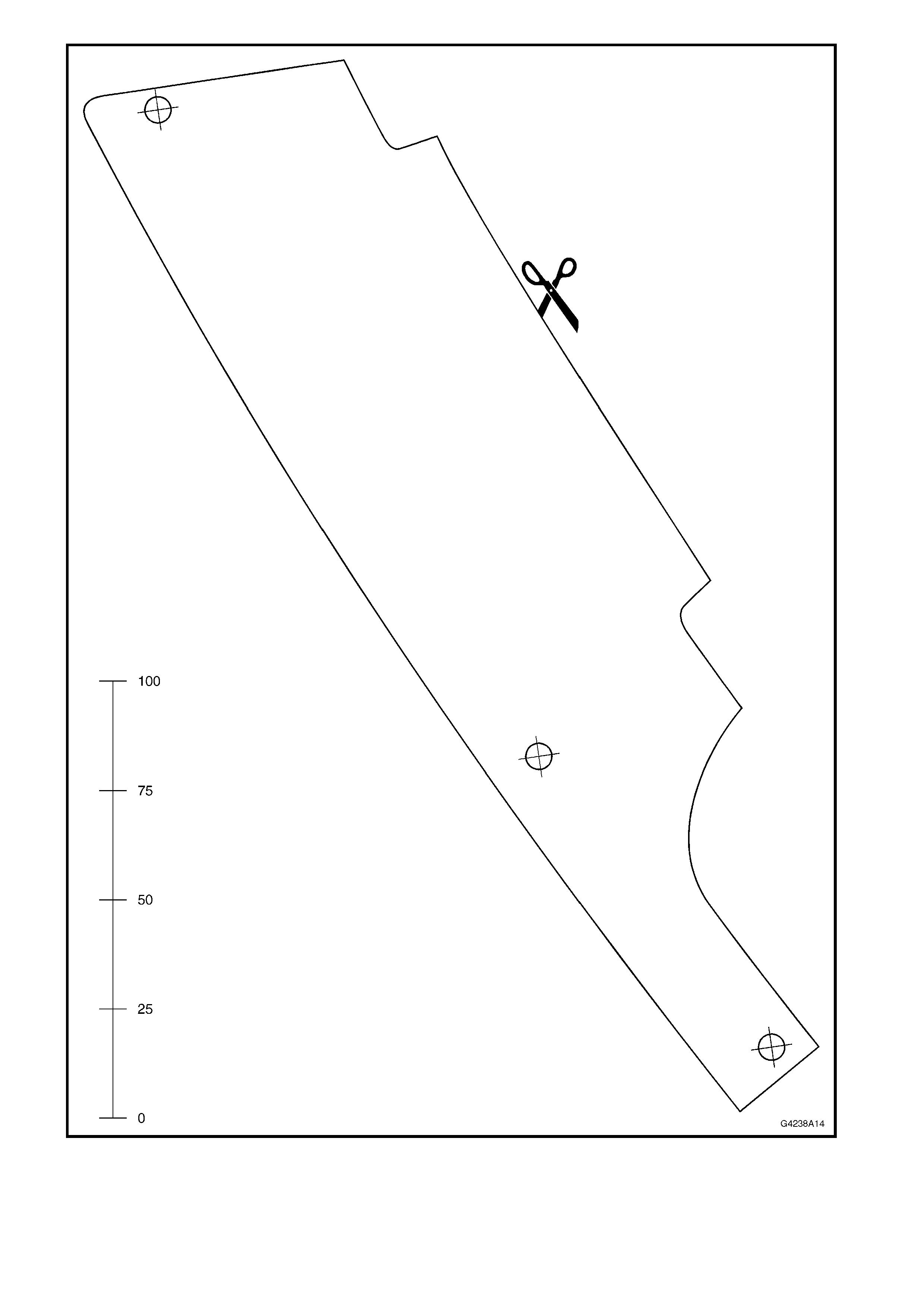
Figure 8A-8
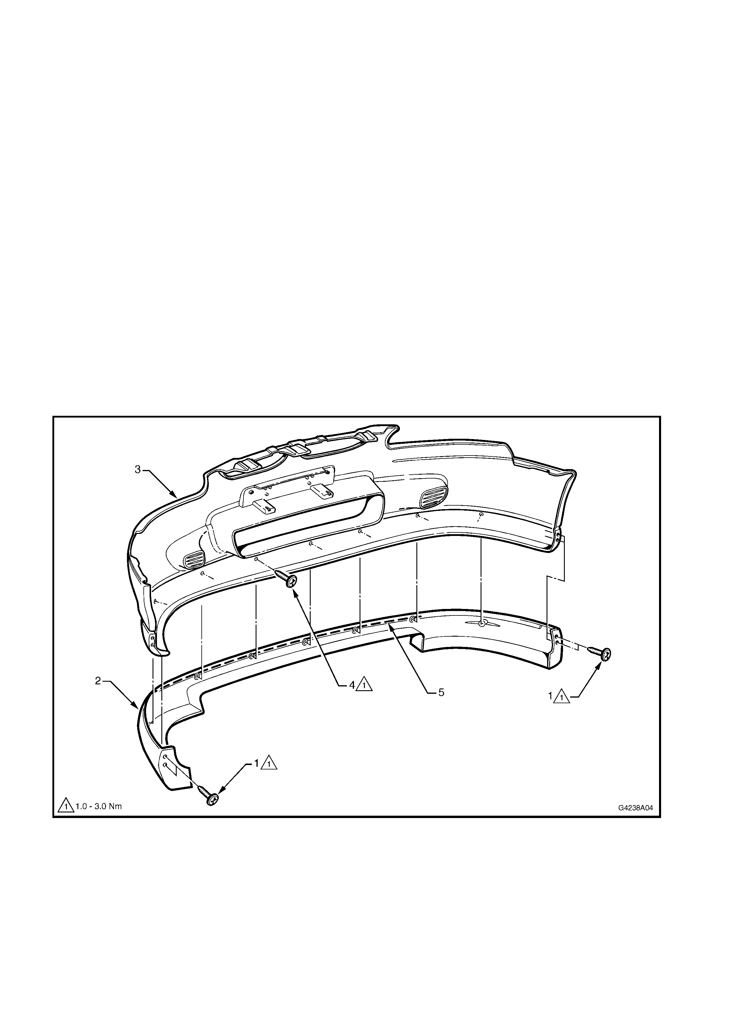
3.0 FRONT APRON
The Holden By Design front apron is attached to the bumper fac ia with screws and urethane adhesive. Two aprons
are available, one for Level 1 vehicles and one for Level 2 & 3 vehicles. For Level 3 vehicles with fog lamps, the
Level 2 & 3 apron requires modifying prior to installation.
NOTE 1: The front bumper facia must be removed prior to the apron. This is required to allow access to the
attaching screws. Refer to Section 1D, BUMPER BARS in the VX Series Service Information for this procedure.
NOTE 2: The front apron is painted in the vehicle’s body colour. The painting procedures are relatively straight
forward, providing the correct steps are followed for PUR (polyurethane). Refer to your paint manufacturer for
further information.
LEVEL 1
REMOVE
1. Place the bumper facia assembly upside down on
a clean, soft surface.
2. Remove the two screws (1) securing each end of
the front apron (2) to the front bumper facia (3).
Refer Fig. 8A-9.
3. Remove the seven screws (4) from the rear side of
the bumper facia.
4. Remove the apron.
NOTE: A bead of urethane adhesive (5) is applied to
the front of the apron. Carefully pulling on the apron
will break the bond.
Figure 8A-9
INSTALL
1. If the bumper facia has not been replaced,
proceed to Step 11.
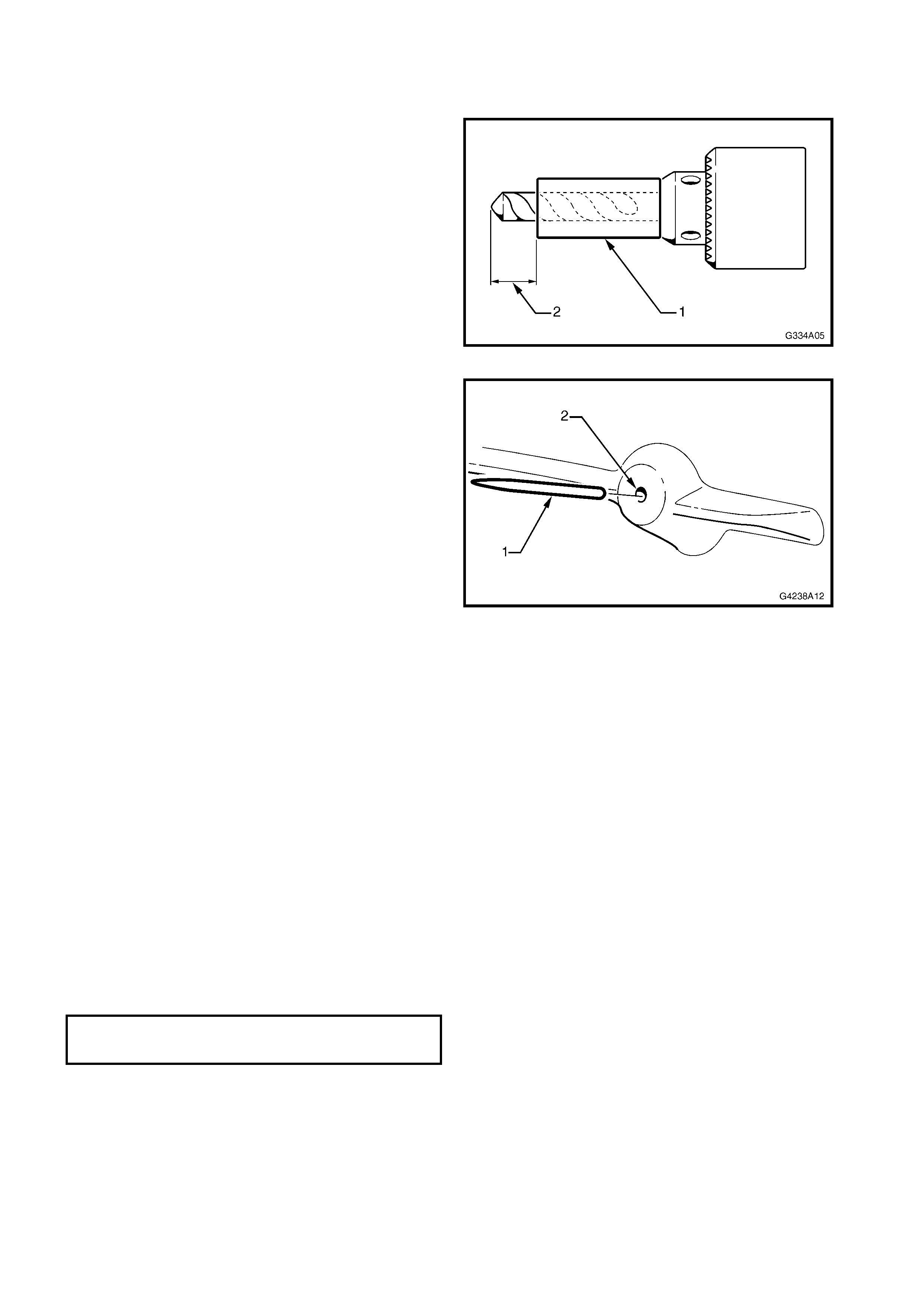
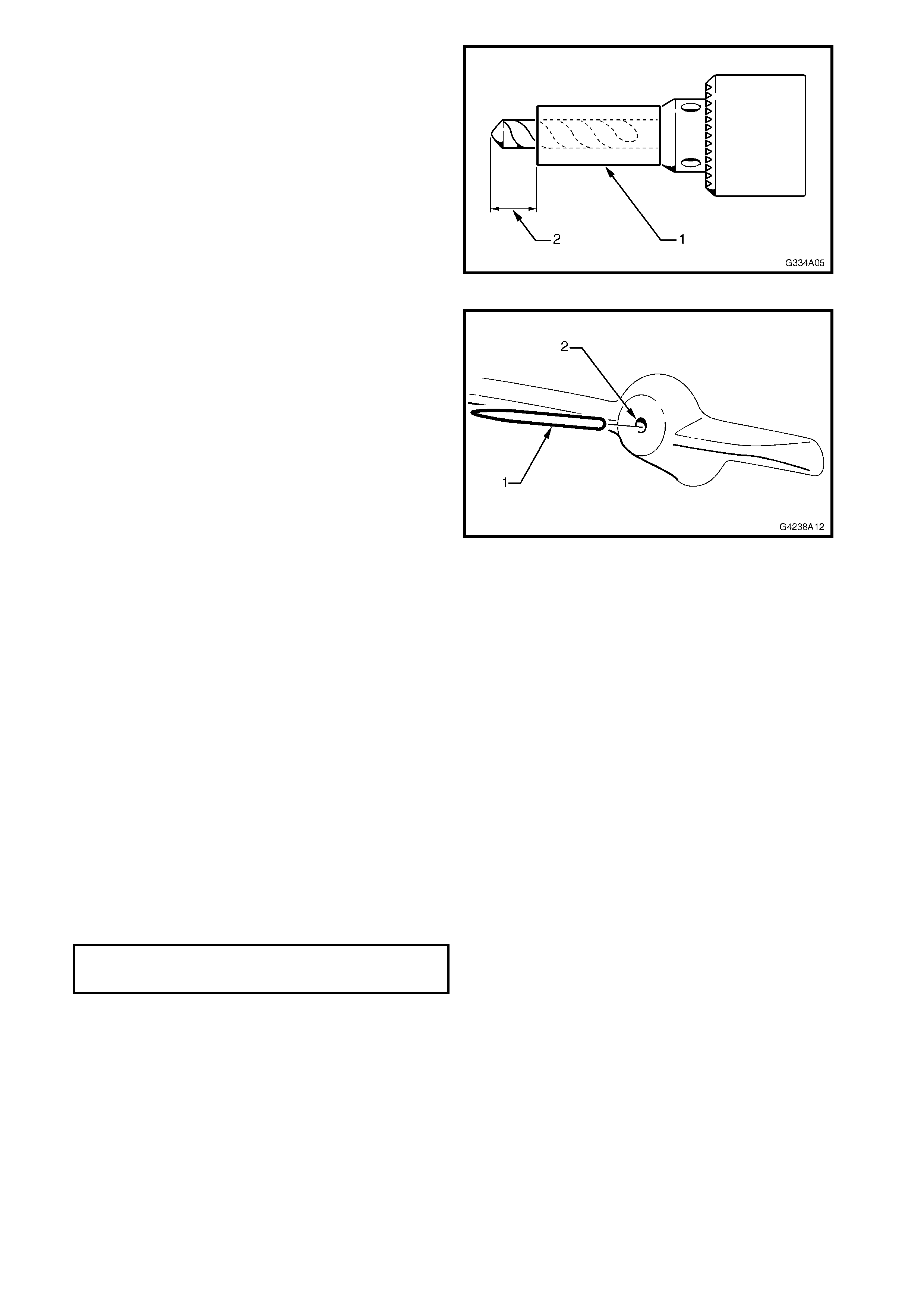
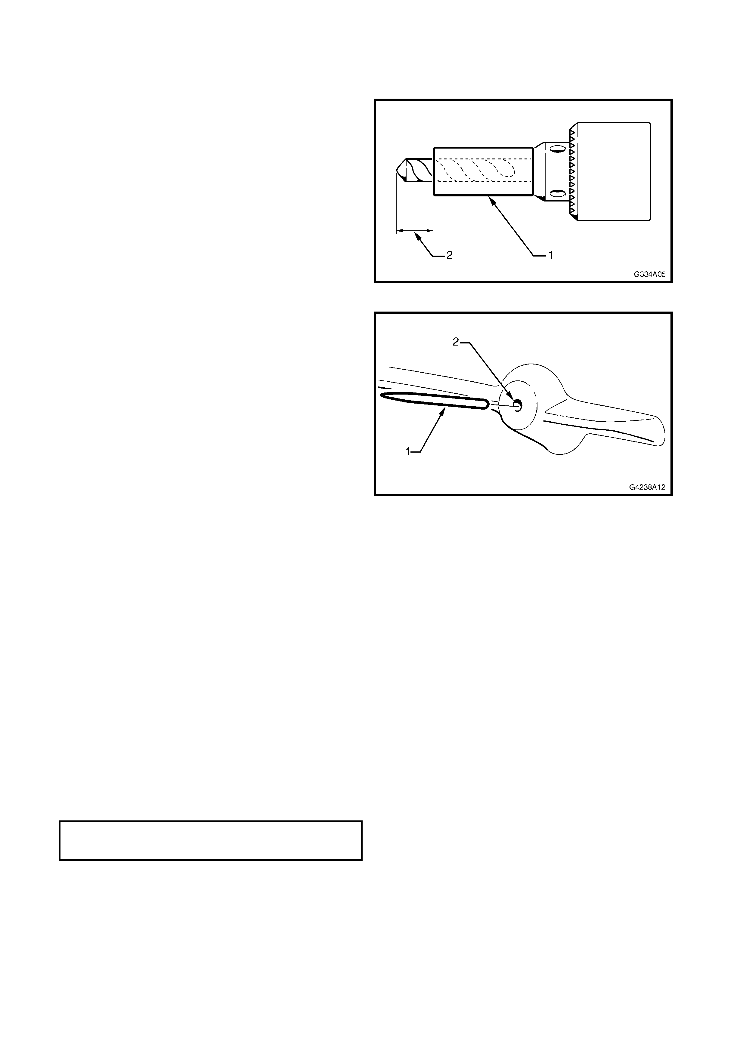
2. Cut a length of tube (1) to fit over a drill-bit to
restrict drill tip depth. The size of the drill-bit is to
be the same diameter as the pins that will be
manufactured in the nex t s tep. T he length f r om the
top of the tube to the end of the drill-bit (2) is to be
8mm.
NOTE: As an alternative, tape can be used.
Figure 8A-10
3. Manufacture the required number of pins (1) from
a length of bronze welding rod or sim ilar. The pins
are to be between 9 to 10mm in length. Sharpen
one end on a grinder.
4. Drill a hole (2) the size of the pins, centrally in each
screw boss on the rear side of the apron.
NOTE: Ensure the dr ill depth is 8m m and the diam eter
no greater than 2.5mm.
5. Insert the pins into the holes. Ensure the end of
the pin is protruding 1 – 2mm.
6. With the aid of an assistant carefully fit the apron
onto the bumper facia.
7. At each screw boss, tap on the apron and facia to
ensure each pin clearly marks the facia.
8. Remove the apron.
9. Drill the facia with the screw holes, 5mm in
diameter.
10. Remove the pins and if required, dr ill out the apr on
pilot holes to 2.5mm.
NOTE: Fit a length of tube or tape to the drill-bit to
ensure the drill depth is no more than 8mm.
Figure 8A-11
11. Apply a bead of urethane adhesive to the front
edge of the apron, refer (5) Fig. 8A-9.
12. Fit the apron onto the bumper facia.
13. From the rear of the f acia, install the s even screws
and tighten to the specified torque.
14. Install the two screws each end of the apron and
tighten to the specified torque.
15. Reinstall the bumper facia as described in
Section 1D, BUMPER BARS in the VX Series
Service Information.
FRONT APRON ATTACHING SCREW
TORQUE SPECIFICATION 1.0 – 3.0Nm
LEVEL 2 & 3
REMOVE
1. Place the bumper facia assembly upside down on
a clean, soft surface.
2. Remove the two screws (1) securing each end of
the front apron (2) to the front bumper facia (3).
Refer Fig. 8A-12.
3. Remove the six screws (4) from the rear side of
the bumper facia.
4. Remove the apron.
NOTE: A bead of urethane adhesive (5) is applied to
the front of the apron. Carefully pulling on the apron
will break the bond.
Figure 8A-12
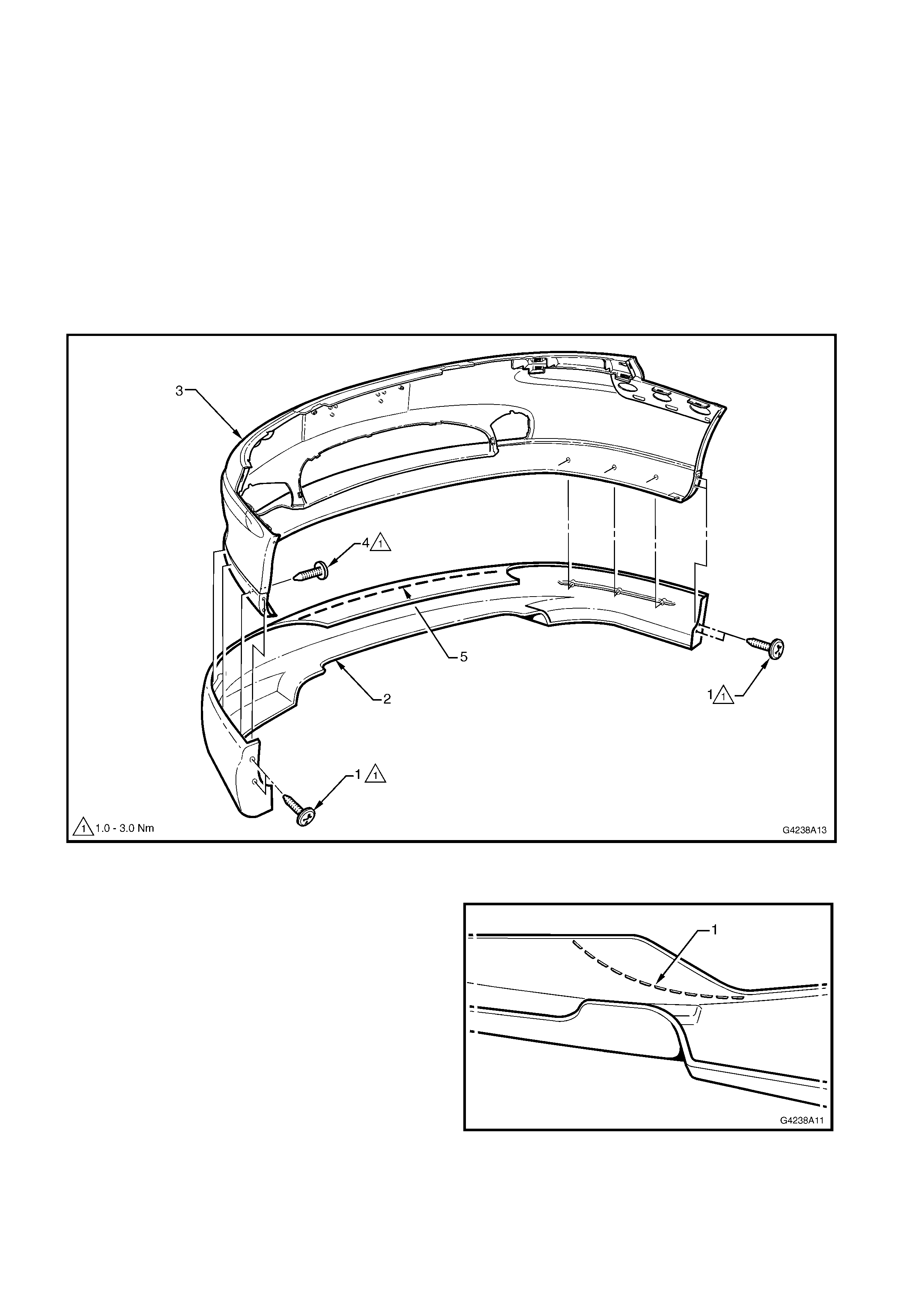
INSTALL
1. If the apron is to be fitted to a Level 3 vehicle with
fog lamps, remove the section shown by cutting
along the line (1) moulded into the apron.
2. Clean up the edge with fine sandpaper.
3. If the bumper facia has not been replaced,
proceed to Step 13.
Figure 8A-13
4. Cut a length of tube (1) to fit over a drill-bit to
restrict drill tip depth. The size of the drill-bit is to
be the same diameter as the pins that will be
manufactured in the next s tep. T he length f r om the
top of the tube to the end of the drill-bit (2) is to be
8mm.
NOTE: As an alternative, tape can be used.
Figure 8A-14
5. Manufacture the required number of pins (1) from
a length of bronze welding rod or sim ilar. The pins
are to be between 9 to 10mm in length. Sharpen
one end on a grinder.
6. D rill a hole ( 2) the size of the pins centrally in each
screw boss on the rear side of the apron.
NOTE: Ensure the dr ill depth is 8m m and the diam eter
no greater than 2.5mm.
7. Insert the pins into the holes. Ensure the end of
the pin is protruding 1 – 2mm.
8. With the aid of an assistant carefully fit the apron
onto the bumper facia.
9. At each screw boss, tap on the apron and facia to
ensure each pin clearly marks the facia.
10. Remove the apron.
11. Drill the facia with the screw holes, 5mm in
diameter.
12. Remove the pins and if r equir ed, drill out the apr on
pilot holes to 2.5mm.
NOTE: Fit a length of tube or tape to the drill-bit to
ensure the drill depth is no more than 8mm.
Figure 8A-15
13. Apply a bead of urethane adhesive to the front
edge of the apron, refer (5) Fig. 8A-12.
14. Fit the apron onto the bumper facia.
15. From the rear of the facia, install the six screws
and tighten to the specified torque.
16. Install the two screws each end of the apron and
tighten to the specified torque.
17. Reinstall the bumper facia as described in
Section 1D, BUMPER BARS in the VX Series
Service Information.
FRONT APRON ATTACHING SCREW
TORQUE SPECIFICATION 1.0 – 3.0Nm
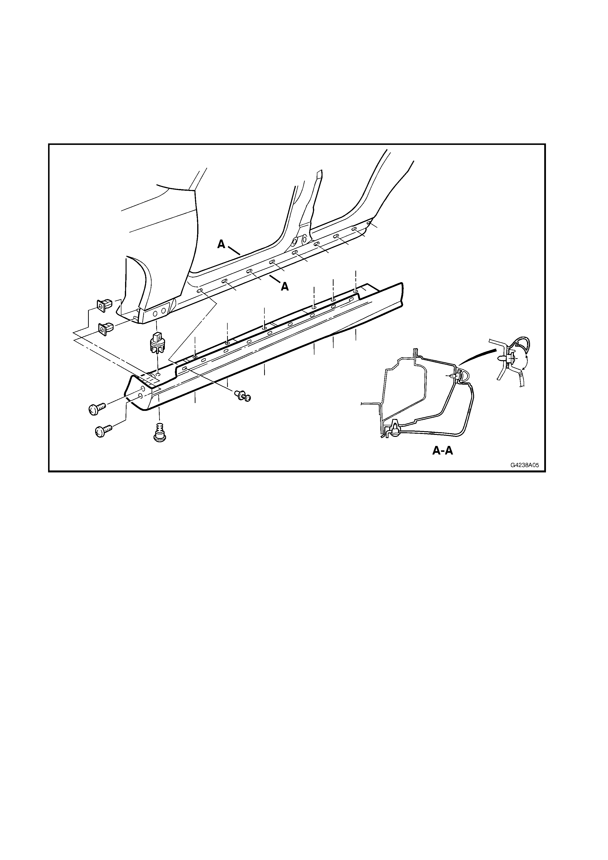
4.0 SIDE SKIRTS
The Holden By Design side skirt assemblies replace the existing rocker panel skirts. The procedure for their
rem oval is the sam e as the standar d skir t. Refer to Sect ion 1A9, EXTERIOR O RNAMENTATION in the VX Series
Service Information for this procedure.
NOTE: The side skirts are painted in the vehicle’s body colour. The painting procedures are relatively straight
forward providing the c or rec t s teps are f ollowed f or PUR ( polyurethane). Refer to your paint manufac turer for fur ther
information.
Figure 8A-16
5.0 REAR APRON
The Holden By Design rear apron is attached to the rear bumper facia with screws and urethane adhesive. Although
there are physical differences between Level 1 and Level 2 & 3 aprons, the service procedures are the same.
NOTE 1: The rear bumper facia must be removed prior to the apron. This is required to allow access to the
attaching screws. Refer Section 1D, BUMPER BARS in the VX Series Service Information for this procedure.
NOTE 2: The rear apron is painted in the vehicle’s body colour. The painting procedures are relatively straight
forward providing the c or rec t s teps are f ollowed f or PUR ( polyurethane). Refer to your paint manufac turer for fur ther
information.
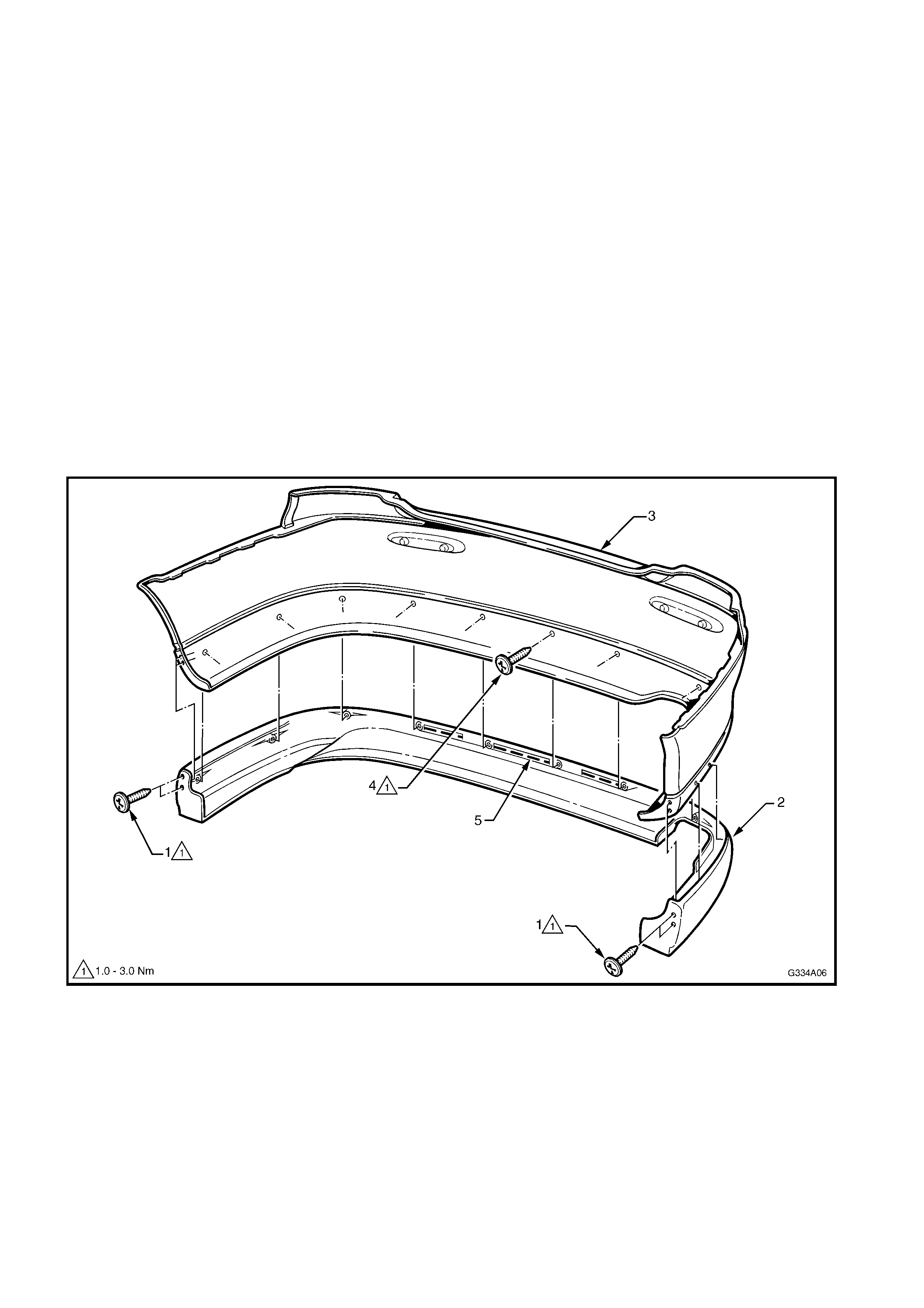
REMOVE
1. Place the bumper facia assembly upside down on
a clean, soft surface.
2. Remove the two screws (1) securing each end of
the rear apron (2) to the rear bumper facia (3).
Refer Fig. 8A-17.
3. Remove the 10 screws (4) from the rear side of
the bumper facia.
4. Remove the apron.
NOTE: A bead of urethane adhesive (5) is applied to
the the apron. Carefully pulling on the apron will break
the bond.
Figure 8A-17
INSTALL
1. If the bumper facia has not been replaced,
proceed to Step 11.
2. Cut a length of tube (1) to fit over a drill-bit to
restrict drill tip depth. The size of the drill-bit is to
be the same diameter as the pins that will be
manufactured in the next s tep. T he length f r om the
top of the tube to the end of the drill-bit (2) is to be
8mm.
NOTE: As an alternative, tape can be used.
Figure 8A-18
3. Manufacture the required number of pins (1) from
a length of bronze welding rod or sim ilar. The pins
are to be between 9 to 10mm in length. Sharpen
one end on a grinder.
4. Drill a hole (2) centrally in each screw boss on the
rear side of the apron, the size of the pins.
NOTE: Ensure the dr ill depth is 8m m and the diam eter
no greater than 2.5mm.
5. Insert the pins into the holes. Ensure the end of
the pin is protruding 1 – 2mm.
6. With the aid of an assistant carefully fit the apron
onto the bumper facia.
7. At each screw boss, tap on the apron and facia to
ensure each pin clearly marks the facia.
8. Remove the apron.
9. Drill the facia with the screw holes, 5mm in
diameter.
10. Remo ve the pins and drill out the apron pilot holes
to 2.5mm, if required.
NOTE: Fit a length of tube or tape to the drill-bit to
ensure the drill depth is no more than 8mm.
Figure 8A-19
11. Apply a bead of urethane adhesive to the front
edge of the apron, refer (5) Fig. 8A-9.
12. Fit the apron onto the bumper facia.
13. From the rear of the facia, install the 10 screws
and tighten to the specified torque.
14. Install the two screws each end of the apron and
tighten to the specified torque.
15. Reinstall the bumper facia as described in
Section 1D, BUMPER BARS in the VX Series
Service Information.
REAR APRON ATTACHING SCREW
TORQUE SPECIFICATION 1.0 – 3.0Nm
6.0 DECKLID SPOILERS
Three Holden By Design decklid spoilers are available. Each is attached to the decklid with screws and nuts, no
adhesive is used.
Although different in style, the servicing of the three spoilers is the same and they share common mounting holes.
NOTE: The s poilers are painted in the vehic le’s body colour. The painting procedures are relatively straight forward
providing the correct steps are followed for PUR (polyurethane with rigid structure foam core material). Refer to your
paint manufacturer for further information.
REMOVE
1. Open the deck lid and r emove the dec k lid inner trim,
if fitted. Refer to Section 1 BODY in the VX Ser ies
Service Information.
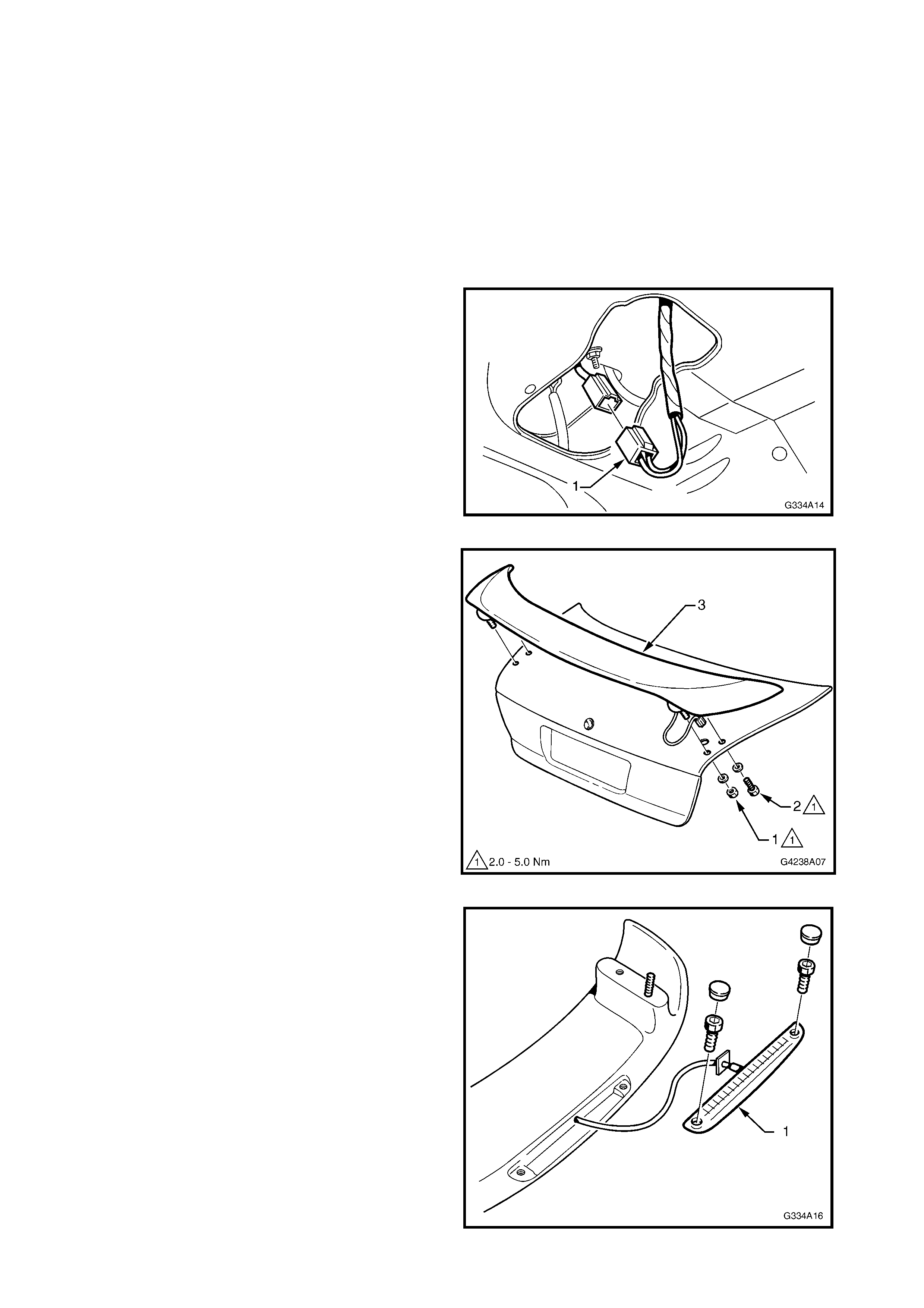
2. Remove each wiring terminal from the spoiler
harness connector body (1) by inserting a scribe or
like into the front side of the connector cavity and
depressing the tab to release the terminal from the
connector body.
Figure 8A-20
3. From the underside of the decklid, remove the nut
(1), screw (2) and washers attaching the spoiler (3).
4. Remove the s poiler, withdrawing the wiring harness
from the RH side.
Figure 8A-21
5. If required, remove the high mount stop lamp
assembly (1).
Figure 8A-22
INSTALL
1. If the decklid has not been replaced, proceed to
Step 8.
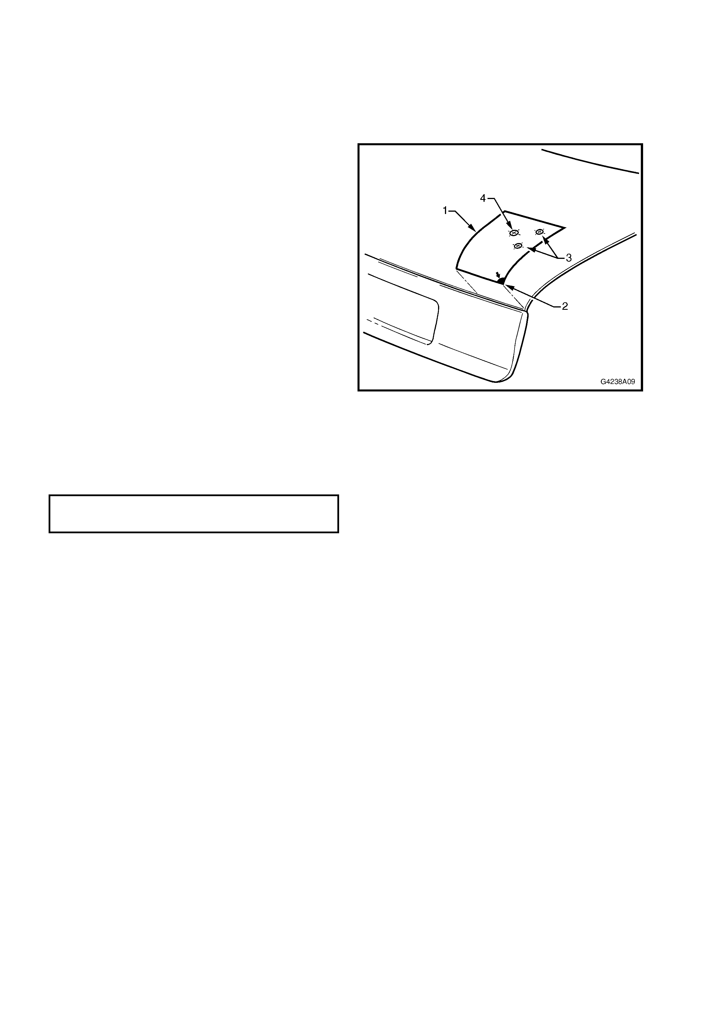
2. Print the drilling template provided in Fig. 8A-24.
NOTE: Ensure the tyemplates prints the correct size
by comparing the scale.
3. Cut out the template (1) and place on the RH side
of the decklid. The arrow (2) is to align with the
corner of the decklid as shown.
4. Mark the mounting holes (3) and for the RH side
only, the wiring harness hole (4).
5. T urn the template over and place it on the LH side
of the decklid. Mark the mounting holes only.
6. Sit the spoiler on the decklid and ensure the
mounting studs align with the marks. Adjust as
required.
7. Carefully drill the mounting holes. Initially drill 3
mm holes, followed by 10 mm holes.
8. Carefully drill the wiring harness hole on the RH
side only. Initially drill a 3mm hole, then drill out to
15mm.
9. Debur the drill holes and apply primer to the bare
metal.
10. Install the high m ount stop lamp onto the spoiler if
required, refer Fig. 8A-22.
11. Fit the spoiler to the decklid, feeding the high
mount stop lamp harness through its hole in the
decklid, refer Fig. 8A-21.
12. Fit the screw, nuts and washers to the studs and
hand tighten.
13. Check alignment of spoiler on decklid and tighten
the screw and nuts to the specified torque.
Figure 8A-23
14. Fit the high mount stop lamp connector pins into
the connector body and join the wiring connector
within the decklid cavity as shown in Fig. 8A-20.
15. Check high mount stop lamp operation.
16. Refit decklid inner trim, if removed.
DECKLID SPOILER ATTACHING SCREW
& NUT TORQUE SPECIFICATION 2.0 – 5.0Nm
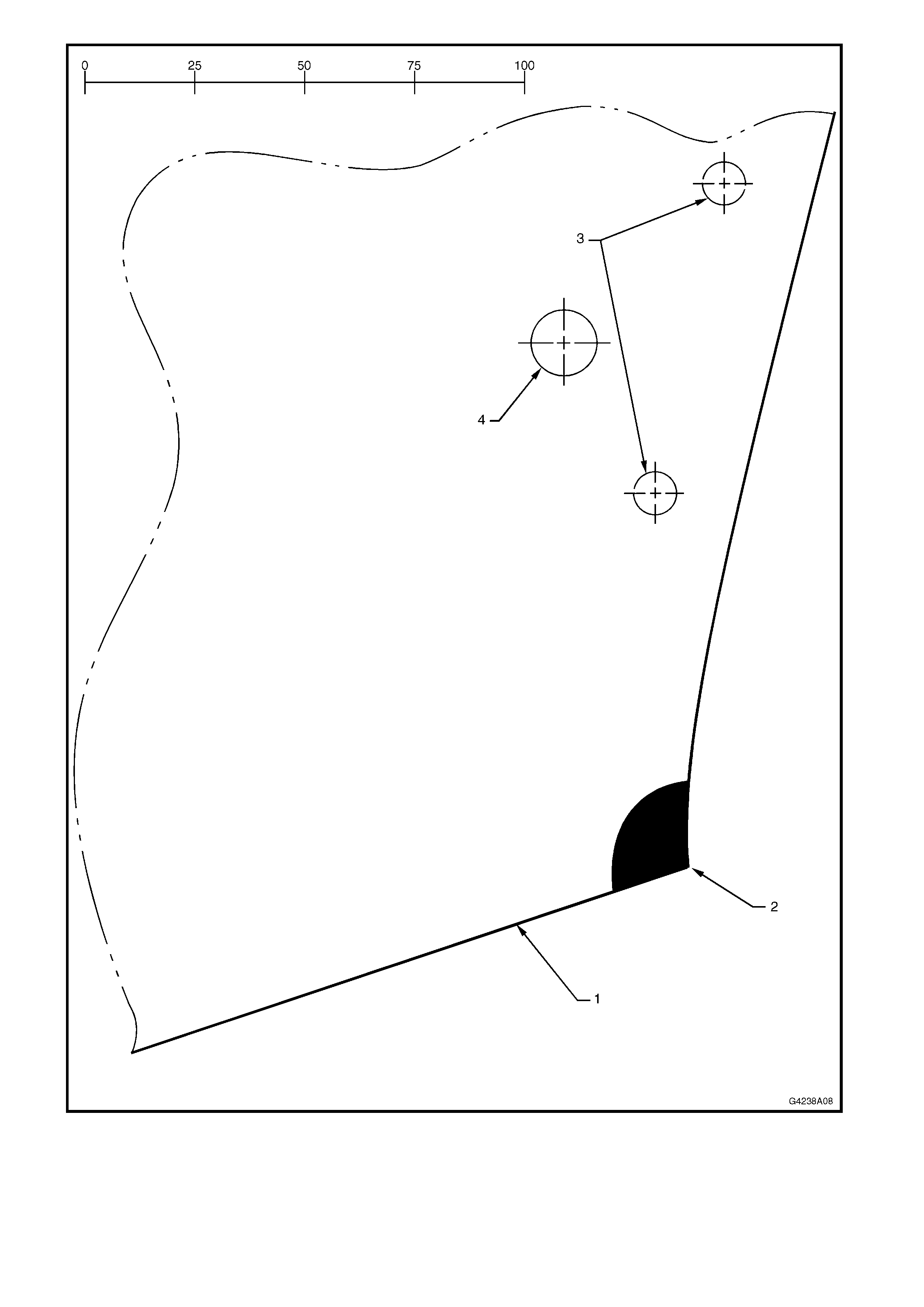
Figure 8A-24
7.0 ALLOY WHEELS
Four alloy wheel styles are available for Holden By Design VX Series vehicles. Each has its own unique styling,
diameter and width. The standard steel rim spare wheel remains fitted.
This Section of the Holden By Design Service Manual Supplement illustrates the wheel types available. For the
information required to service wheels for VX Series vehicles, refer to Section 10 WHEELS & TYRES in the VX
Series Service Information.
Figure 8A-25
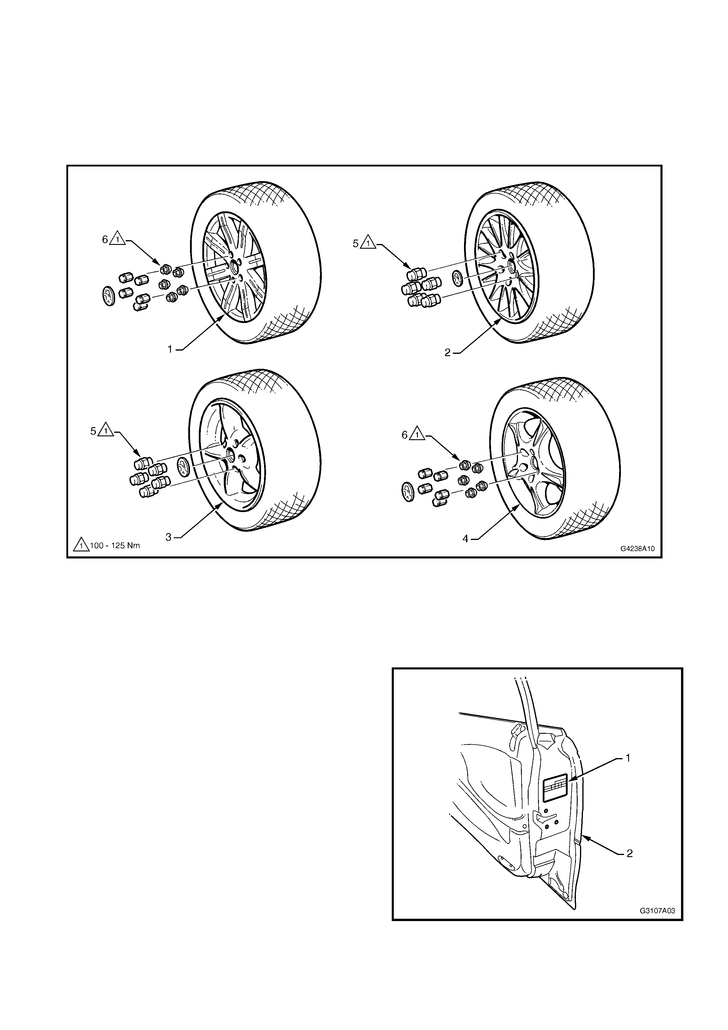
Legend
1. X - Series 8-spoke alloy wheel 17” x 8” 4. C - Series 5-spoke alloy wheel 17” x 8”
2. T - Series Multi-spoke alloy wheel 16” x 7.5” 5. Alloy wheel nut
3. RT - Series 5-spoke alloy wheel 17” x 8” 6. Wheel nut with cap
When a Holden By Design alloy wheel and tyre
pack age is fitted, the standar d tyre placard (1); located
on the end surface of the right-hand front door (2), is
replaced with a new placard.
Figure 8A-26

The tyre placard provides information on the specific
tyre and wheel package fitted to the vehicle.
Figure 8A-27
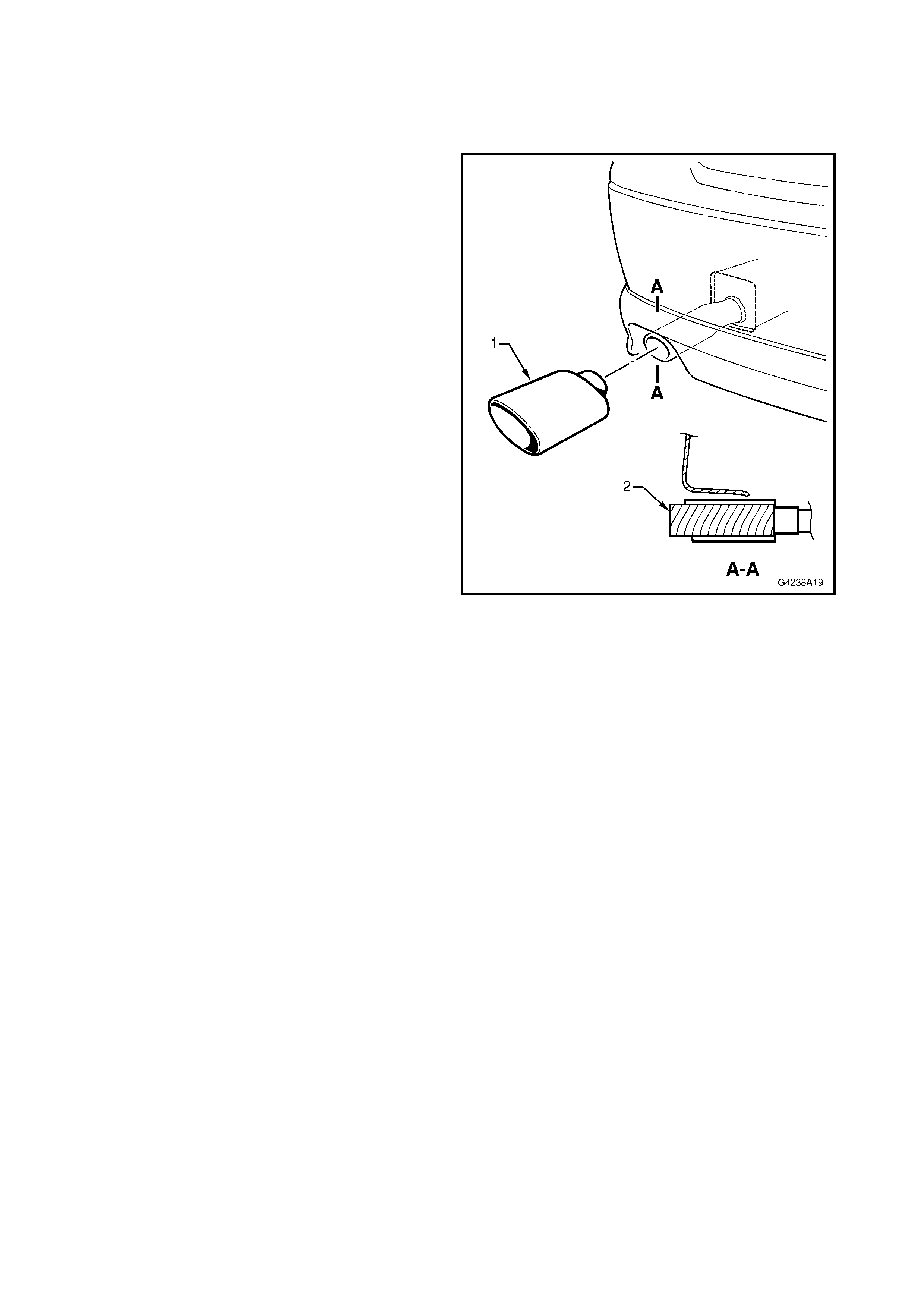
8.0 EXHAUST EXTENSION
W her e a f ull Holden By Design body kit has been installed, a c hrom e finished exhaus t extension is f itted to Level 2
and 3 vehicles.
REMOVE
1. Using a hammer and bloc k of wood seated against
the front edge of the extension(1), knock the
extension off the exhaust pipe.
INSTALL
1. Seat the extension on to the exhaust pipe.
2. Place a block of wood (2) within the extension,
seated against the front wall.
3. Knock the extension onto the exhaust pipe with a
hammer until it is level with the rear apron.
Figure 8A-28
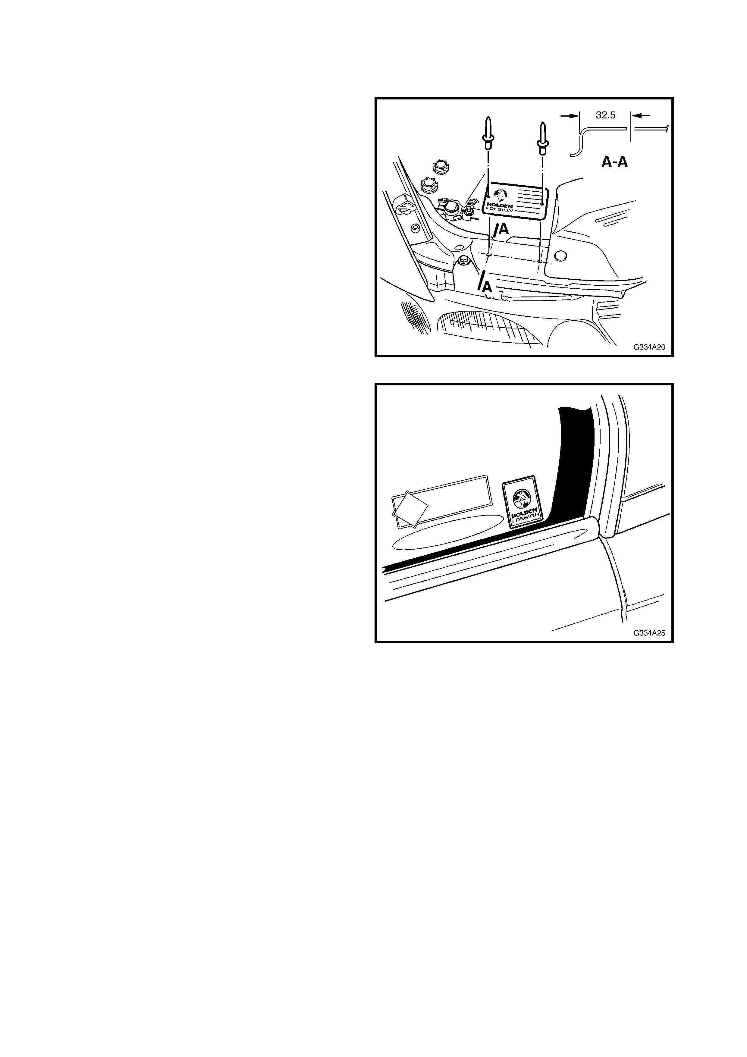
9.0 IDENTI FICATION & DECALS
Where a full Holden By Design body kit has been installed, a HBD identification plate is installed in the engine
compartment on the front upper panel. Holden By Design labels are also placed on each rear door fixed glass.
1. Drill 3 mm holes to the dimensions shown into the
front panel upper.
2. Affix the identification plate with pop-rivets.
Figure 8A-29
The Holden By Design decal is affixed to the inside of
each rear door fixed window as shown.
NOTE: Ensure the surface is clean and dry before
applying the decal.
Figure 8A-30

10.0 TORQUE WRENCH SPECIFICATIONS
Radiator grille insert mesh attaching screw .......................................................................................1.0 – 2.0 Nm
Radiator grille insert attaching screw .................................................................................................0.2 – 0.4 Nm
Radiator grille insert attaching nut......................................................................................................1.0 – 3.0 Nm
Front apron attaching screw...............................................................................................................1.0 – 3.0 Nm
Rear apron attaching screw ...............................................................................................................1.0 – 3.0 Nm
Decklid spoiler attaching screw..........................................................................................................2.0 – 5.0 Nm
Decklid spoiler attaching nut ..............................................................................................................2.0 – 5.0 Nm
Alloy wheel attaching nut............................................................................................................110.0 – 140.0 Nm