
SECTION 9A - VU SERIES HBD PACKAGES
1.0 GENERAL INFORM ATION
This Section of the Holden By Design Service Information Supplement describes the service procedures for the
hard tonneau cover, which is part of the Holden By Design packages available for VU Series utility vehicles.
The other pac k ages available are als o fitted to other vehic les; theref ore ref erenc e should be made to the applicable
Service Information Sections as described in 1.1 VU Series HBD Package References.
The hard tonneau c over is painted in the vehicle’s body colour and is hinged at the f ront. Gas struts aid in opening
the tonneau cover and support it while open. Two keyed locks secure the tonneau cover when closed and provide
security for items stored in the load compartment.
Painting procedures for the hard tonneau cover are not provided in this Supplement, as the products used in the
refinish industry vary significantly. The hard tonneau is manufactured from fibreglass; therefore the correct
procedures for refinishing this material, as specified by the paint manufacturer, must be followed.

1.1 VU SERIES HBD PACKAGE REFERENCES
Package Refer
Hard Tonneau This Supplement
Alloy Wheels:
16 x 7.5 T-Series Multi-spoke Wheel & 225/50 B530 Tyre
17 x 8 C-Series 5 Spoke Wheel & 235/45 V Tyre
17 x 8 RT-Series 5 Spoke Wheel & 235/45 V Tyre
17 x 8 X-Series 8 Spoke Wheel & 235/45 V Tyre
Section 8A, VX Series Body Kit & Alloy Wheels in the
Holden By Design Service Information Supplement
Brakes (Only with 17” Wheels):
Performance Brakes
Premium Brakes
Section D, Brakes in the VX Series Holden Special
Vehicles Service Information Supplement
Holden By Design Radiator Grille Insert (Except SS) Section 8A, VX Series Body Kit & Alloy Wheels in the
Holden By Design Service Information Supplement
Country Roo Bar (Except SS) Section 4F, VT Series Country Driving & Load
Management in the Holden By Design Service
Information Supplement
Cruise Control (Except S & SS) VT Commodore cruise control accessories fitting
instructions for the applicable motor on this Service
Information Package, together with Section 12E Cruise
Control in the VU Series Service Information
Audible Alarm VT Commodore Series II anti-theft alarm package
accessories fitting instructions on this Service
Information Package, together with Section 12F Theft
Deterrent in the VU Series Service Information
Leather Bound Steering Wheel Section 4E, VT Series Comfort, Security &
Convenience in the Holden By Design Service
Information Supplement together with Section 9A
Steering in the VU Series Service Information
Power Antenna Section 4E, VT Series Comfort, Security &
Convenience in the Holden By Design Service
Information Supplement together with Section 12D
Audio System in the VT Series Service Information
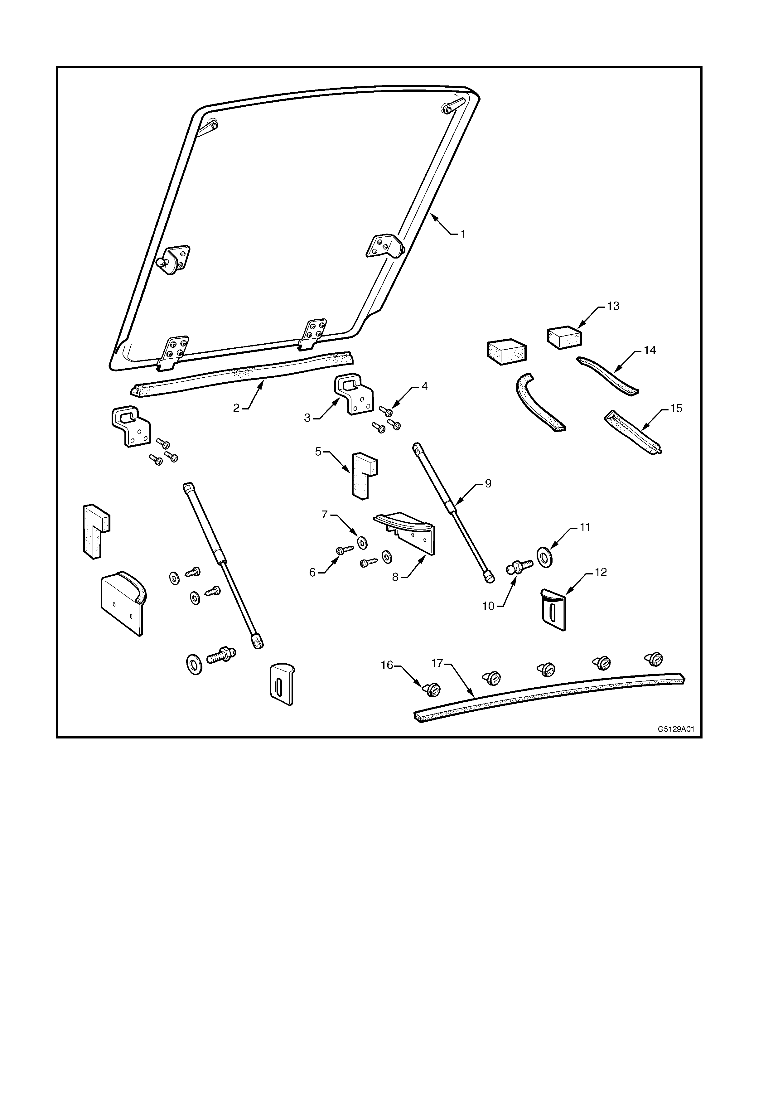
2.0 HARD TONNEAU
Figure 9A-1
Legend
1. Tonneau Cover Assembly 7. Seal Plate Washer 13. Seal - Drain *
2. Front Upper Panel Seal 8. Seal Plate 14. Seal - Cap *
3. Hinge Slot Plate 9. Gas Strut 15. Seal - Endgate *
4. Hinge Slot Plate Screw 10. Gas Strut Ball Screw 16. Nutsert - Centre Roof Rear Cap #
5. L-Shaped Foam Pad 11. Gas Strut Ball Screw Wa sher 17. Adhesive Tape - Roof Rear Cap #
6. Seal Plate Screw 12. Lock Plate
* Part of load compartment area seal kit, sold separately.
# Part of centre roof rear cap repair kit, sold separately.
2.1 TONNEU COVER ASSEMBLY
REMOVE
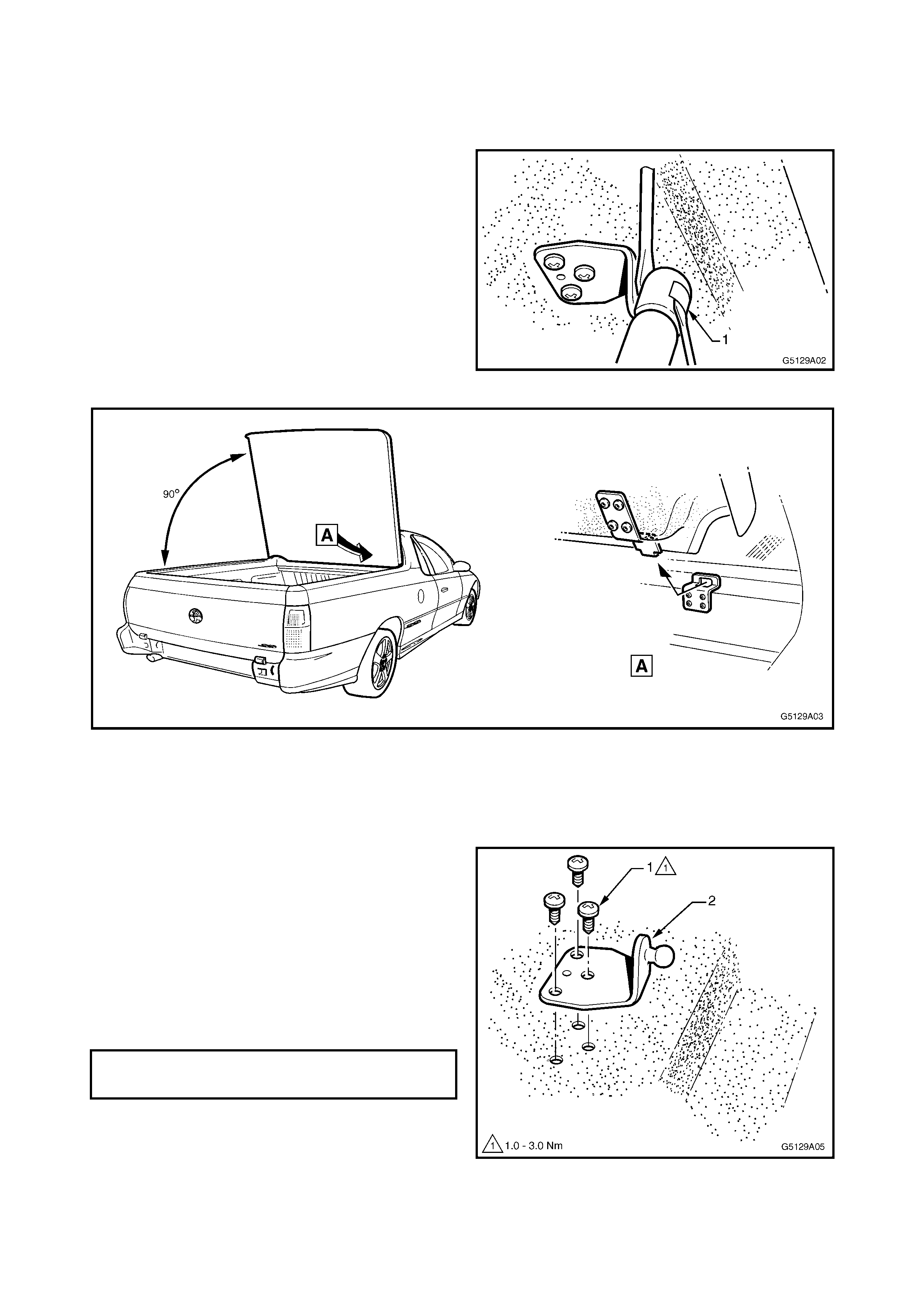
1. Open the tonneau cover and have an assistant
support the opposite side.
2. Insert a small flat blade screwdriver under the
spring clip ( 1) on the strut end and pris e the clip
outward: Do not remove.
3. Lever the strut from the strut bracket. Repeat
for the opposite side.
4. Carefully raise the tonneau cover to nearly 90
degrees and withdraw the hinge tongues from
the hinge slots, refer Fig. 9A-3.
5. Store the tonneau cover in a safe place.
Figure 9A-2
Figure 9A-3
DISASSEMBLE
1. Carefully place the tonneau cover upside down
on a soft surface.
REMOVE – GAS STRUT BRACKET
1. Remove the three screws (1) attaching the gas
strut bracket (2) and remove the bracket.
REINSTALL – GAS STRUT BRACKET
1. Place the bracket in position ensuring correct
orientation.
2. Install the three screws and tighten to the
specified torque.
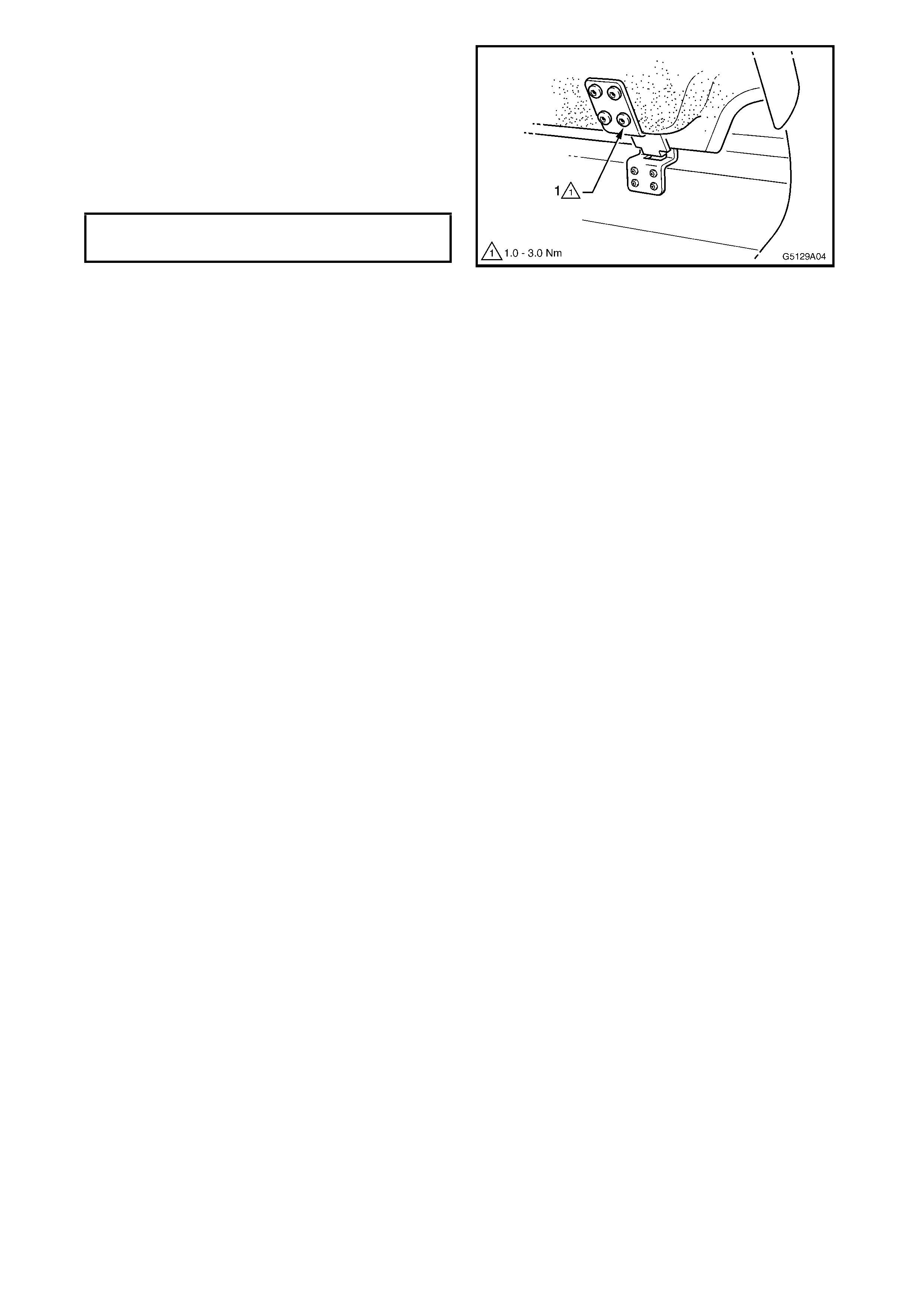
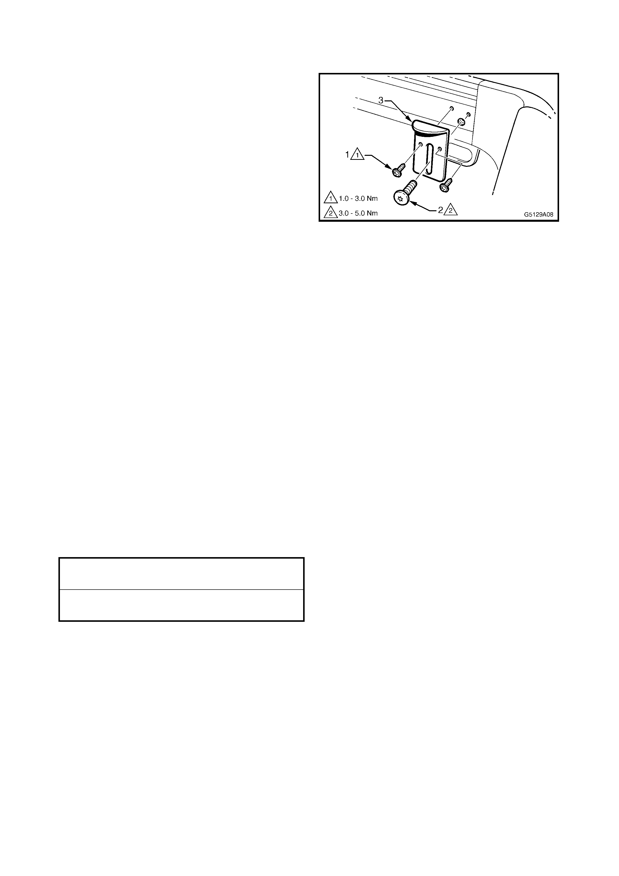
Figure 9A-4
GAS STRUT BRACKET ATTACHING
SCREW TORQUE SPECIFICATION 1.0 – 3.0 Nm
REMOVE – HINGE TONGUE PLATE
1. Remove the four screws (1) attac hing the hinge
tongue plate (2) and remove the plate.
REINSTALL – HINGE TONGUE PLATE
1. Place the hinge tongue plate in position, install
the screws and tighten to the specified torque.
Figure 9A-5
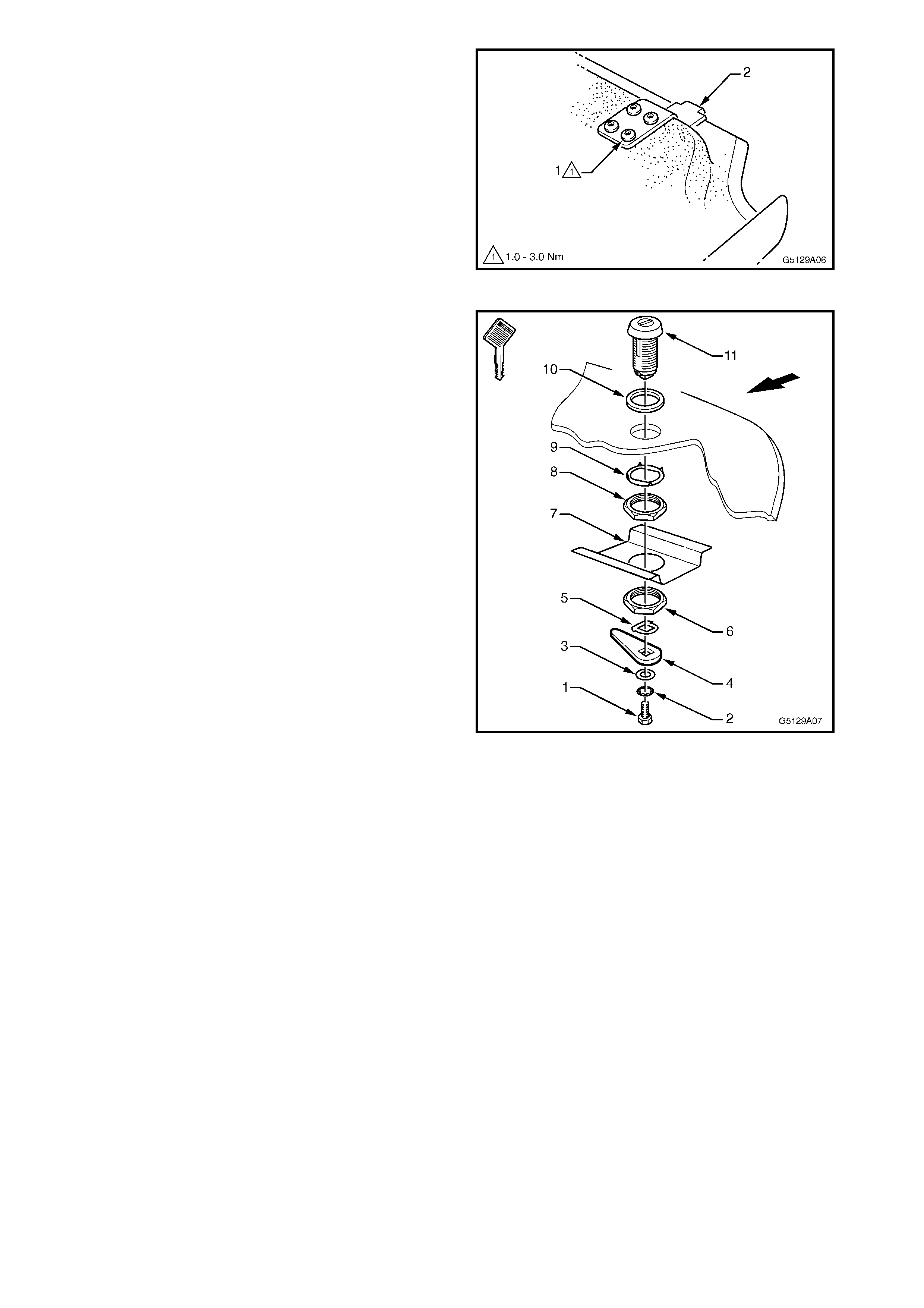
REMOVE – LOCK ASSEMBLY
1. Remove the screw (1) shake proof washer (2)
and flat washer (3) attaching the latch plate (4).
2. Remove the latch plate and locating plate (5).
3. Remove the nut (6) and support plate (7).
4. Remove the nut (8) and anti-rotation ring (9)
and withdraw the lock barrel (11) and seal ring
(10) from the tonneau cover.
REINSTALL – LOCK ASSEMBLY
1. Reinstall the components in the correct order
ensuring their correct orientation. The locating
plate lug at the base of the loc k barr el should be
facing forward.
2. Tighten the nuts and screw tightly.
3. Chec k for c orrec t operation. T he key slot should
be parallel to the vehicle when the lock is in the
open and closed positions.
Figure 9A-6
REINSTALL
1. If not done so, install all seals for the hard
tonneau cover, refer 2.5 SEALS.
2. With the aid of an assistant, install the tonneau
cover by r aising its r ear to near 90 degrees and
insert the hinge tongue plates into the hinge
slots, refer Fig. 9A-3.
NOTE: Tak e care not to dam age the tonneau c over
or vehicle.
3. Lower the tonneau to allow the gas struts to be
attached to the strut brackets. A 'click' will be
heard when the strut is seated correctly.
NOTE 1: Ensure the hinge tongues are fully inserted
into the hinge slots.
NOTE 2: Ensure the cylinder end of the strut is up.
4. Close the tonneau carefully and check its
alignment around each side and the rear.
5. If adjustment is required, open the tonneau and
disconnect the gas struts from the tonneau by
inserting a small screwdriver under the spring
clip on the strut end and prise the clip outward:
do not remove. Remove the strut.
6. Loosen the screws (1) attaching each hinge to
the tonneau cover with a 5mm Allen key. Open
the endgate and have an as sistant lie in the tr ay
on their back with the Allen key.
7. Close the tonneau and manoeuvre it into the
correct position. When correctly aligned each
side and rear, have the assistant tighten the
hinge screws to the specified torque.
8. While the assistant is in the rear compartment,
check the seal plates are in contact with the
tonneau. Adjust as required.
9. Open the tonneau cover and reconnect the gas
struts.
10. Close the tonneau and check the locking action
each side. Adjust the lock plates as required,
refer 2.2 LOCK PLATE.
Figure 9A-7
TONNEAU COVER HINGE TONGUE
SCREW TORQUE SPECIFICATION 1.0 – 3.0 Nm
2.2 LOCK PLATE
REMOVE
1. Remove the lock plate lock-screws (1), 2
places.
2. Using a T40 Torx head bit, remove the screw
(2) and remove the lock plate (3).
Figure 9A-8
REINSTALL
1. Place the lock plate in position and install the
Torx-head screw.
2. Close the tonneau and check the locking action.
3. Raise or lower the lock plate until slight
pressur e on the tonneau is required for the lock
to be operated.
4. Tighten the Torx head screw to the specified
torque.
5. If the exis ting lock plate is us ed, install the lock -
screws.
NOTE: The lock-screws are used to maintain the
lock plate in its factory set position. If this position is
now diff erent, new holes will be required adjacent to
the existing holes.
6. If a new loc k plate is being f itted, install the lock
screws level with the top of the slot.
NOTE 1: The screws are self-drilling.
NOTE 2: If attaching the plate to the existing rail
cap, install the screws either 5 mm higher or lower
to avoid interfering with the original holes.
7. Tighten the screws to the specified torque.
LOCK PLATE ATTACHING SCREW
TORQUE SPECIFICATION 3.0 – 5.0 Nm
LOCK PLATE LOCK-SCREW
TORQUE SPECIFICATION 1.0 – 3.0 Nm
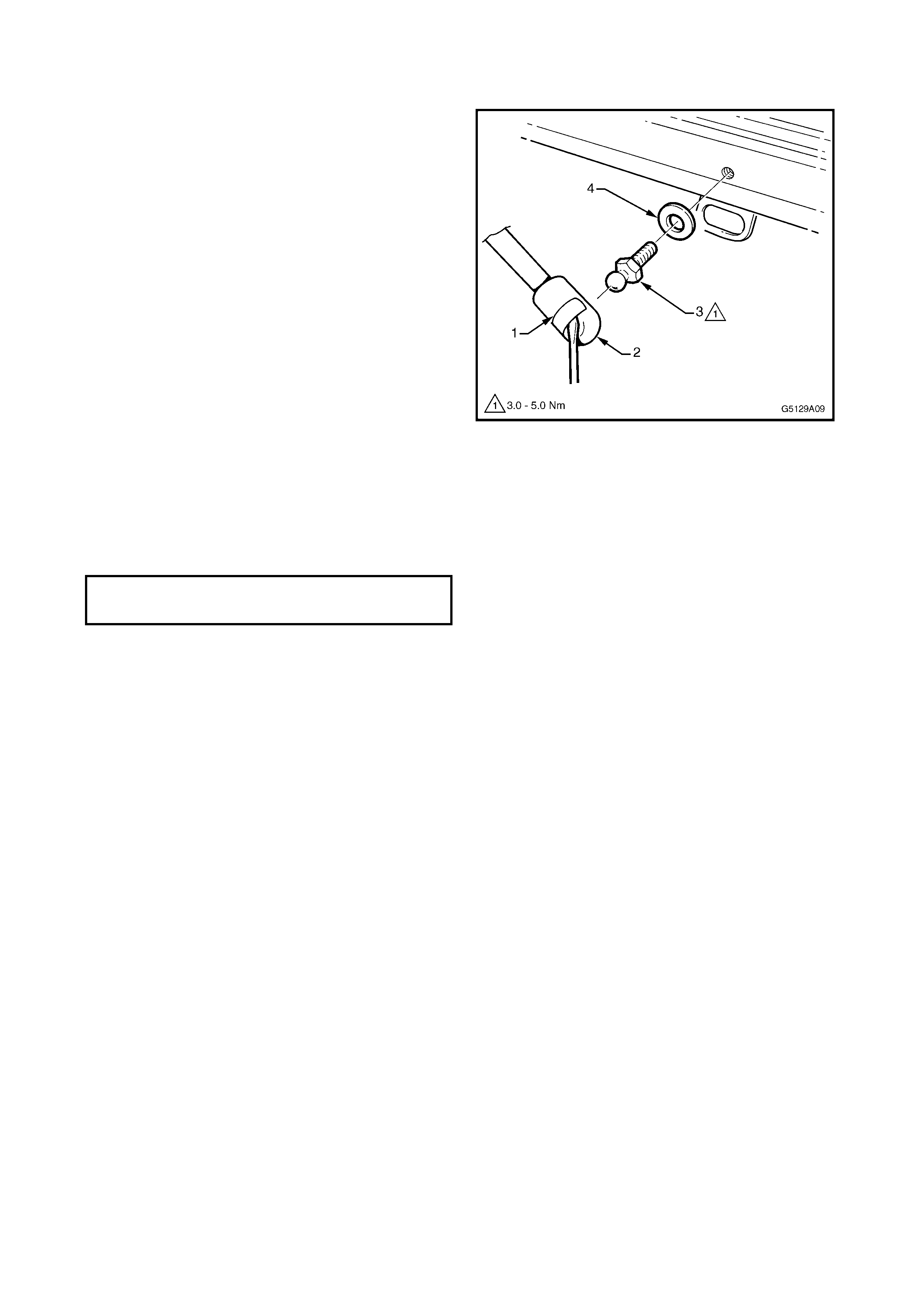
2.3 GAS STRUT BALL SCREW
REMOVE
1. Insert a small flat blade screwdriver under the
spring clip (1) on the strut end (2) and prise the
clip outward. Do not remove.
2. Lever the strut from the ball screw (3).
3. Remove the ball screw and washer (4).
Figure 9A-9
REINSTALL
1. Install the washer and ball sc rew. Tighten to the
specified torque.
2. Reconnect the gas strut.
GAS STRUT BALL SCREW
TORQUE SPECIFICATION 3.0 – 5.0 Nm
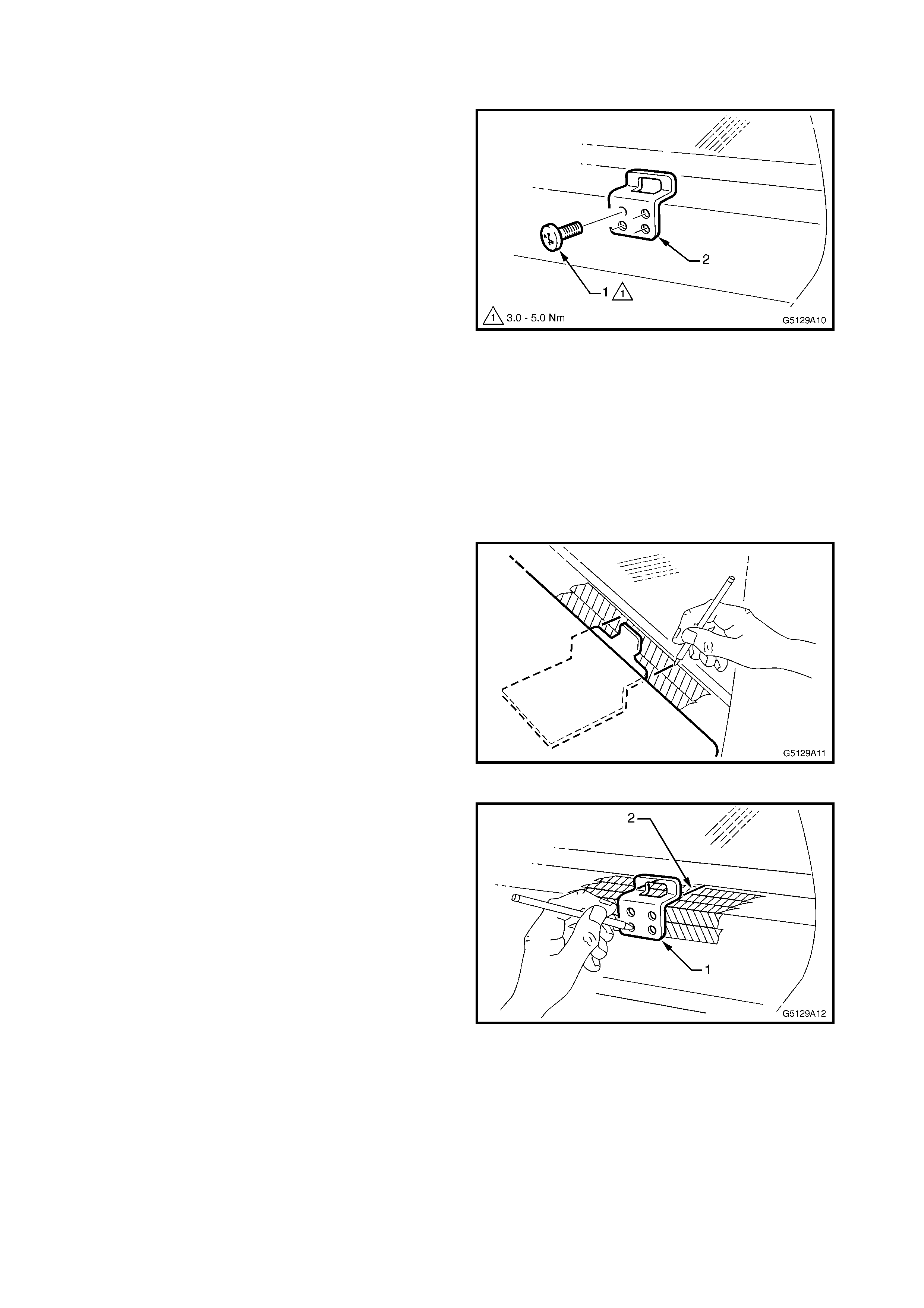
2.4 HINGE SLOT PLATE
REMOVE
1. Remove the pan-head screw (1), four places
attaching the hinge slot plate (2) to the vehicle.
Figure 9A-10
REINSTALL
NOTE: If the nutserts have not been removed,
proceed to step 13.
1. To avoid paint damage, place masking tape on
the panel where each hinge will be.
2. With the aid of an assistant, place the hard
tonneau in position on the vehicle and
centralise.
3. Mark a line on the load compartment front upper
panel, each side of the hinge.
4. As required, repeat for the opposite hinge.
5. Remove the tonneau cover from the vehicle.
Figure 9A-11
6. Align the hinge slot plate (1) with the marks on
the load compartment front upper panel (2).
7. Using the hinge slot as a template, mark the
screw hole positions.
8. Dill four 6 mm pilot holes.
9. Drill the pilot holes out to 9.5 mm.
10. Remove the masking tape.
11. Vacuum up any swarf and paint the holes with
corrosion protection primer.
12. Using a commercially available nutsert tool,
insert a M6 nutsert in each hole.
Figure 9A-12
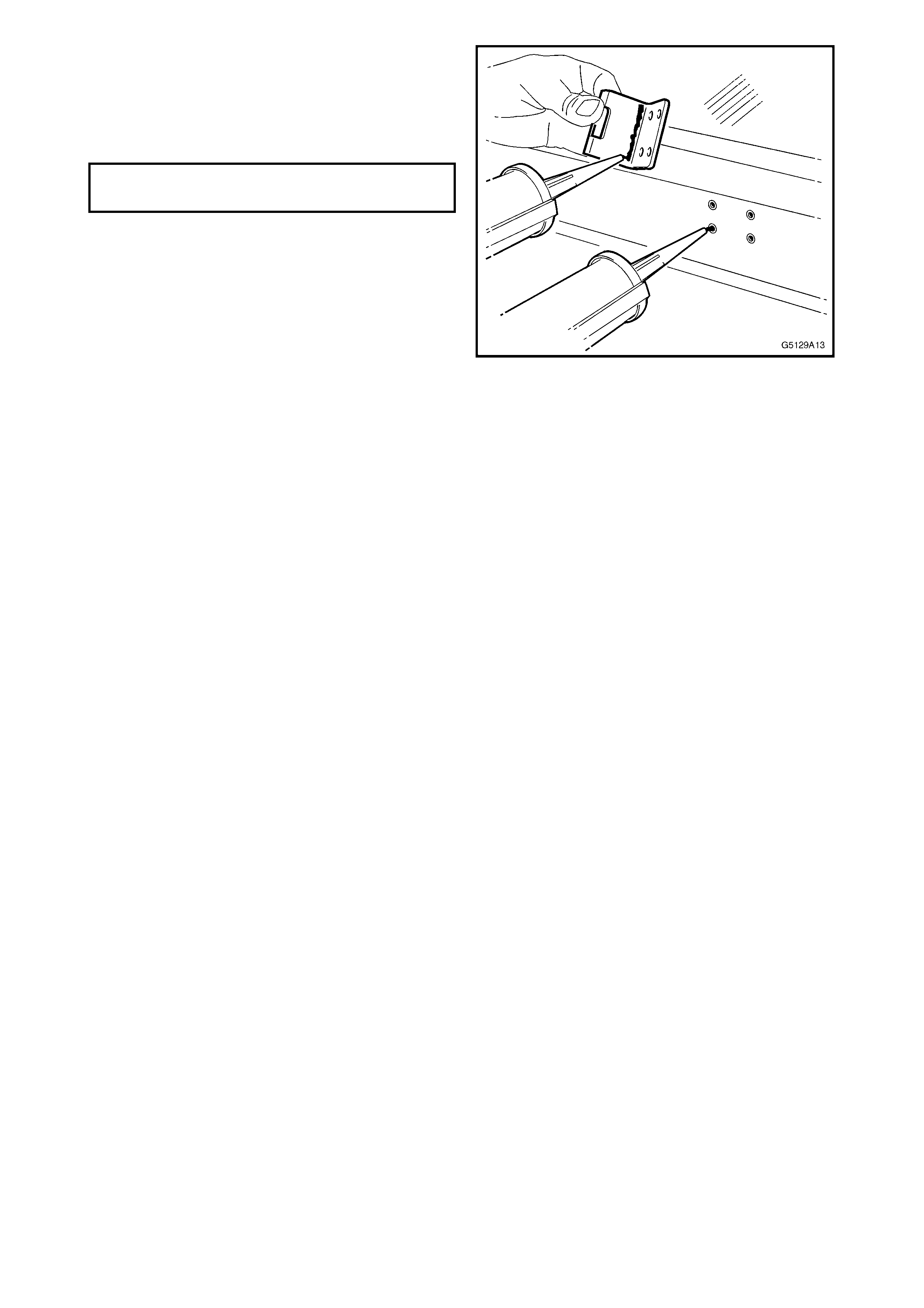
13. Apply silicone or butyl sealer to the mounting
surface of the hinge slot plate and on each
screw hole.
14. Install the hinge slot plate and pan-head screws.
Tighten to the specified torque.
Figure 9A-13
HINGE SLOT PLATE SCREW
TORQUE SPECIFICATION 3.0 – 5.0 Nm
2.5 SEALS
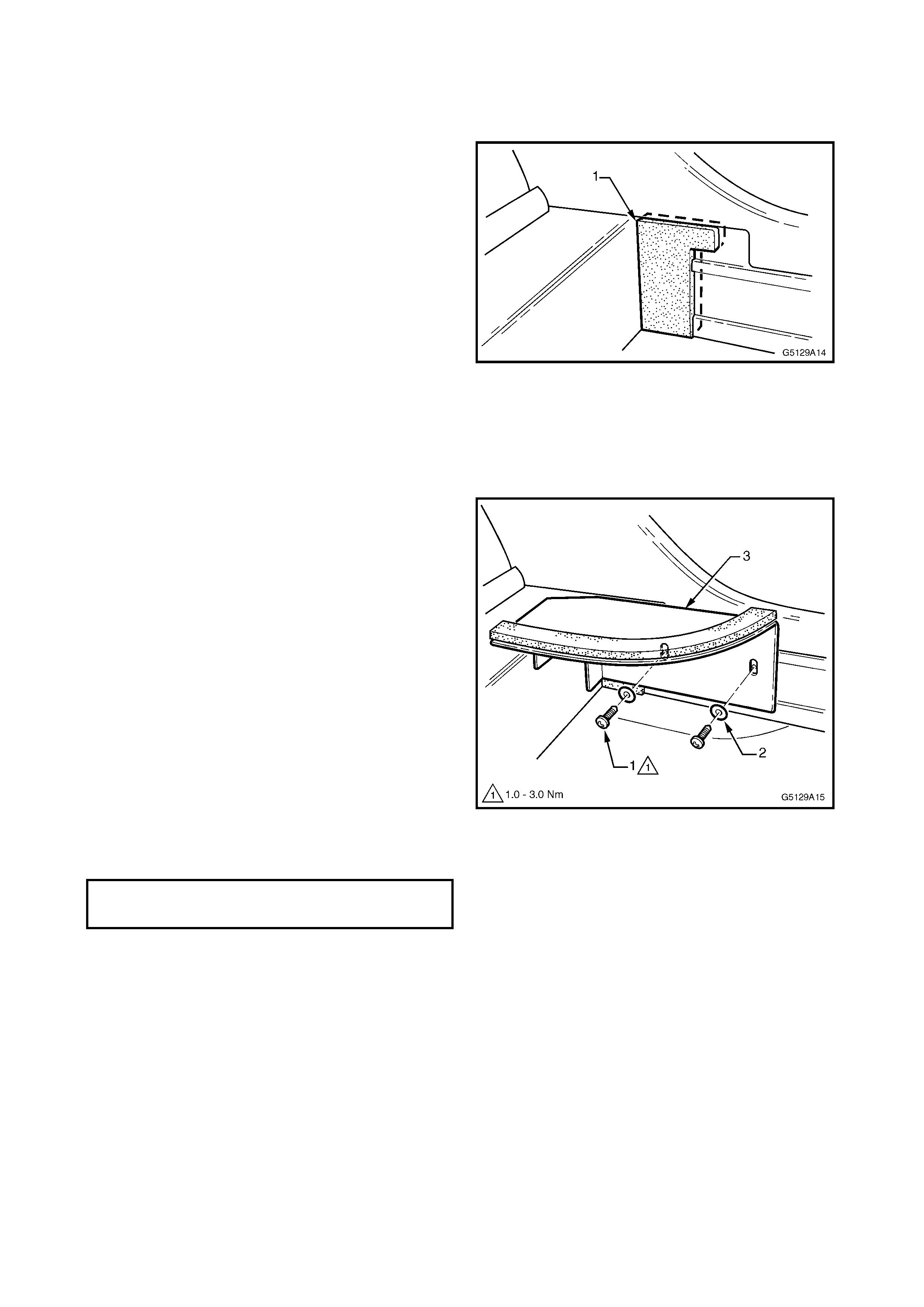
L-SHAPED FOAM PAD
REMOVE
NOTE: The L-shaped foam pad (1) is adhesive
backed and removal may damage the pad, which
must then be replaced.
1. Insert a narr ow scraper or knife under the lower
edge of the pad and car efully prise the pad from
the vehicle.
REINSTALL
1. Clean the surface of the vehicle where the pad
is to be fitted.
2. If a new pad is being fitted, remove the backing
paper. If the existing undamaged pad is being
fitted, apply contact adhesive such as Quick-
Grip or equivalent to the back of the pad.
3. Install the pad as shown.
Figure 9A-14
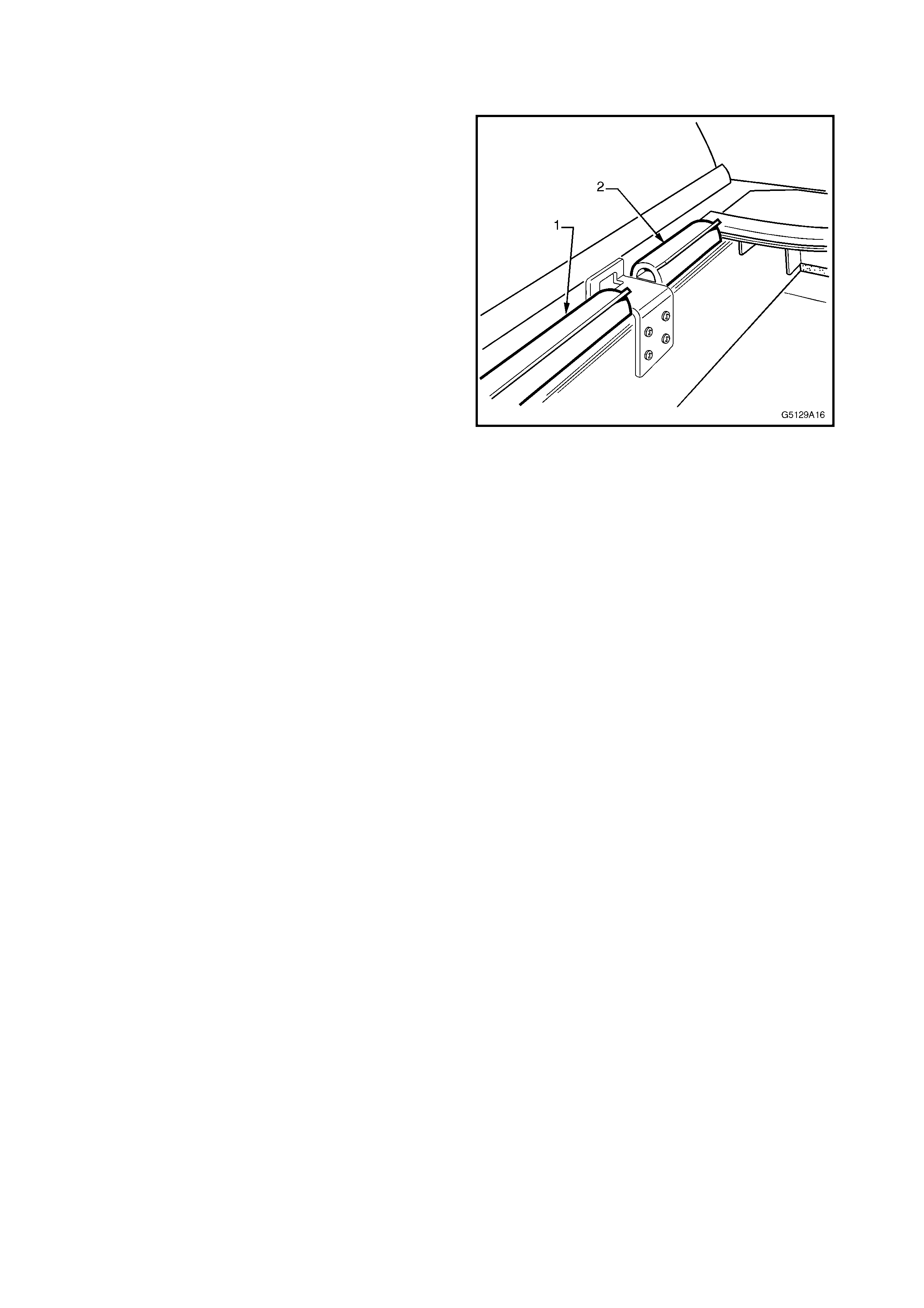
SEAL PLATE
REMOVE
1. Remove the two screws (1) and washers (2)
attaching the seal plate (3) to the vehicle and
remove.
REINSTALL
1. Fit the seal plate in position against the load
compartment front upper panel. Ensure the top
surface of the plate is sitting on the panel.
2. Install the screws and washers in the middle
position in each slot. Do not tighten.
NOTE: The screws are self-drilling if the existing
holes no longer exist.
3. If removed, install the tonneau cover as
described in Section 2.1 TONNEAU COVER.
4. Open the endgate and close the tonneau cover.
5. From within the rear compartment, adjust the
seal plate so that it is in contact with the
tonneau cover.
6. Tighten the screws to the specified torque.
Figure 9A-15
SEAL PLATE SCREW
TORQUE SPECIFICATION 1.0 – 3.0 Nm
FRONT UPPER PANEL SEALS
REMOVE
NOTE: The front upper panel seals are adhesive
backed and removal may damage the seal, which
must then be replaced.
1. Carefully prise the front upper panel seal -
centre (1) or outer (2) from the vehicle, taking
care not to damage the seal or paintwork.
REINSTALL
NOTE: New seals are supplied in the one piece,
which is to be cut to length as required.
1. Clean the surface of the vehicle where the
seal(s) are to be fitted.
2. If a new seal is being f itted, cut it to length. The
centre seal is to f it between the hinge slot plates
and the two outer seals are to fit between the
hinge slot plate and seal plate each side.
3. Remove the backing paper, or if an existing
undamaged seal is being fitted, apply contact
adhesive such as Quick-Grip or equivalent to
the back of the seal.
4. Install the seal as shown, noting that the lip of
the seal is facing rearward.
Figure 9A-16
CAP SEAL & DRAIN SEAL
NOTE 1: The cap and drain seals are part of the
load compartment area seal kit, available
separately.
NOTE 2: The cap and drain seals are adhesive
backed. Removal may damage the seals, which
must then be replaced.
NOTE 3: The centre roof rear cap is affixed to the
vehicle with retainers inserted into nutserts and
double-sided tape. On removal of the cap, the
double-sided tape will be destr oyed and some of the
nutserts m ay be damaged. If required, a centre roof
rear cap repair kit is available which includes these
parts.
REMOVE
1. Remove the c entre roof rear c ap (1) by carefully
spreading each end of the cap to disengage the
locking tabs (2), refer Fig. 9A-17.
2. Insert a flat blade screwdriver and clean shop
rag between the lower edge of the centre roof
rear cap and the rear window.
3. Ensuring the lock ing tabs are disengaged, prise
the cap off in an upward and rearward direction.
NOTE: The upper edge of the cap is attached with
double sided tape.
4. Where fitted, disconnect the high mount stop
lamp connector (3) and remove the cap.
5. Remove the screw (4) attaching the side roof
rear cap (5).
6. Rotate the cap rearward to disengage the three
clips and ease the lower end of the c ap forward
to disengage the cap from the side rail capping.
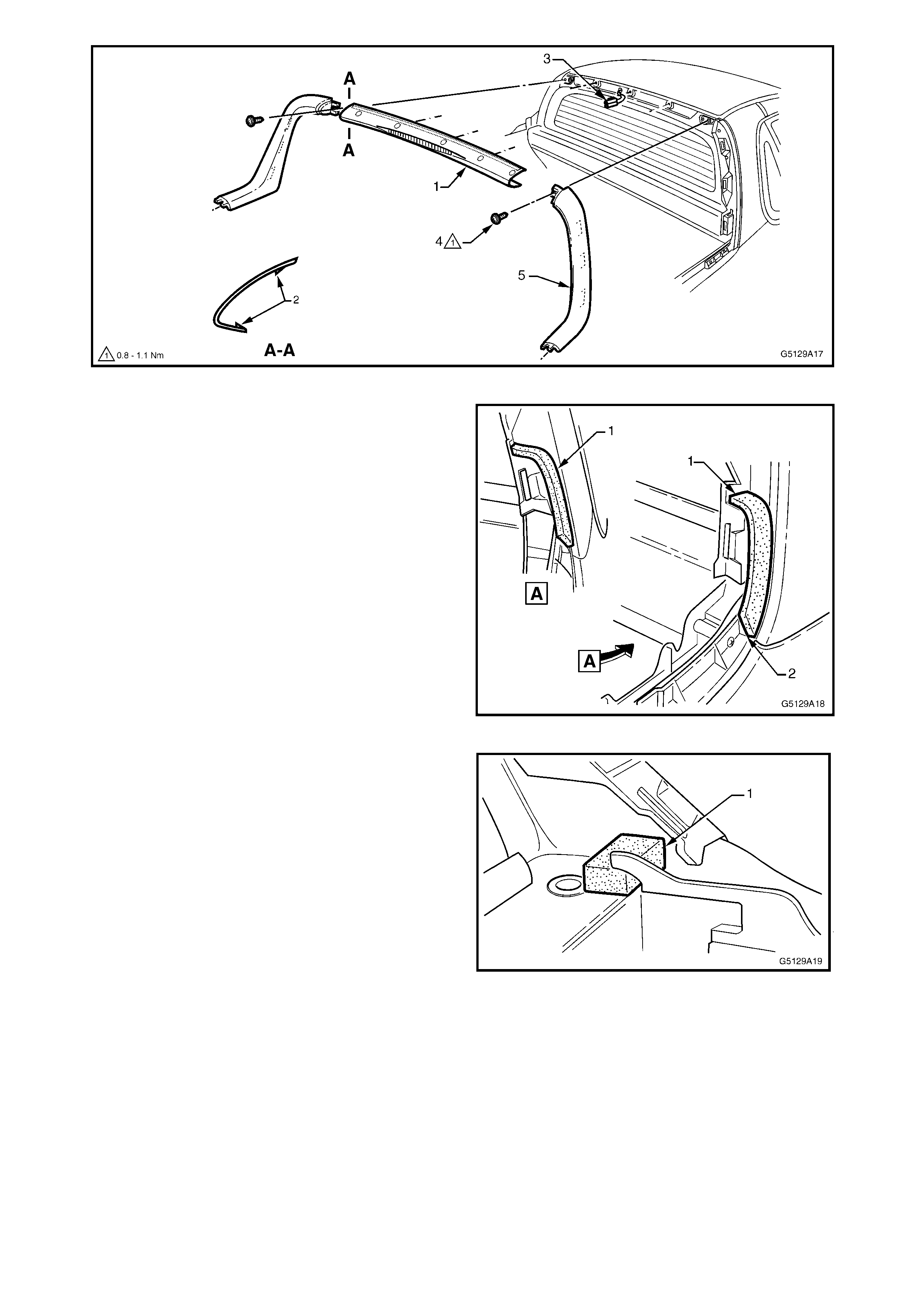
Figure 9A-17
7. Peel the cap seal (1) from the quarter panel
upper moulding.
8. Clean off any residual adhesive as required.
Figure 9A-18
9. Peel the drain seal (1) from the front upper
panel.
10. Clean off any residual adhesive as required.
REINSTALL
1. Clean the surfaces with wax and grease
remover such as Prepsol or equivalent.
2. If the existing seal(s) are being used, apply
contact adhesive such as Quick-Grip or
equivalent to the seal, or remove the backing
paper if a new seal(s) is being fitted.
3. Install the drain seal as shown in Fig. 9A-19,
ensuring it is seated against the side panel.
4. Install the cap seal as shown in Fig. 9A-18,
ensuring the upper end is seated aganst the
quarter panel upper m oulding and the lower end
is seated on the rib (2).
NOTE: It is important the seal is applied in such a
way that it is not visible when the cap is fitted.
5. Installation of the roof rear caps is the reverse
of removal.
NOTE: Replace the double-sided tape and nutserts
as r equired using the centre roof rear cap repair k it,
available seperately. Follow the instructions supplied
with the kit.
Figure 9A-19
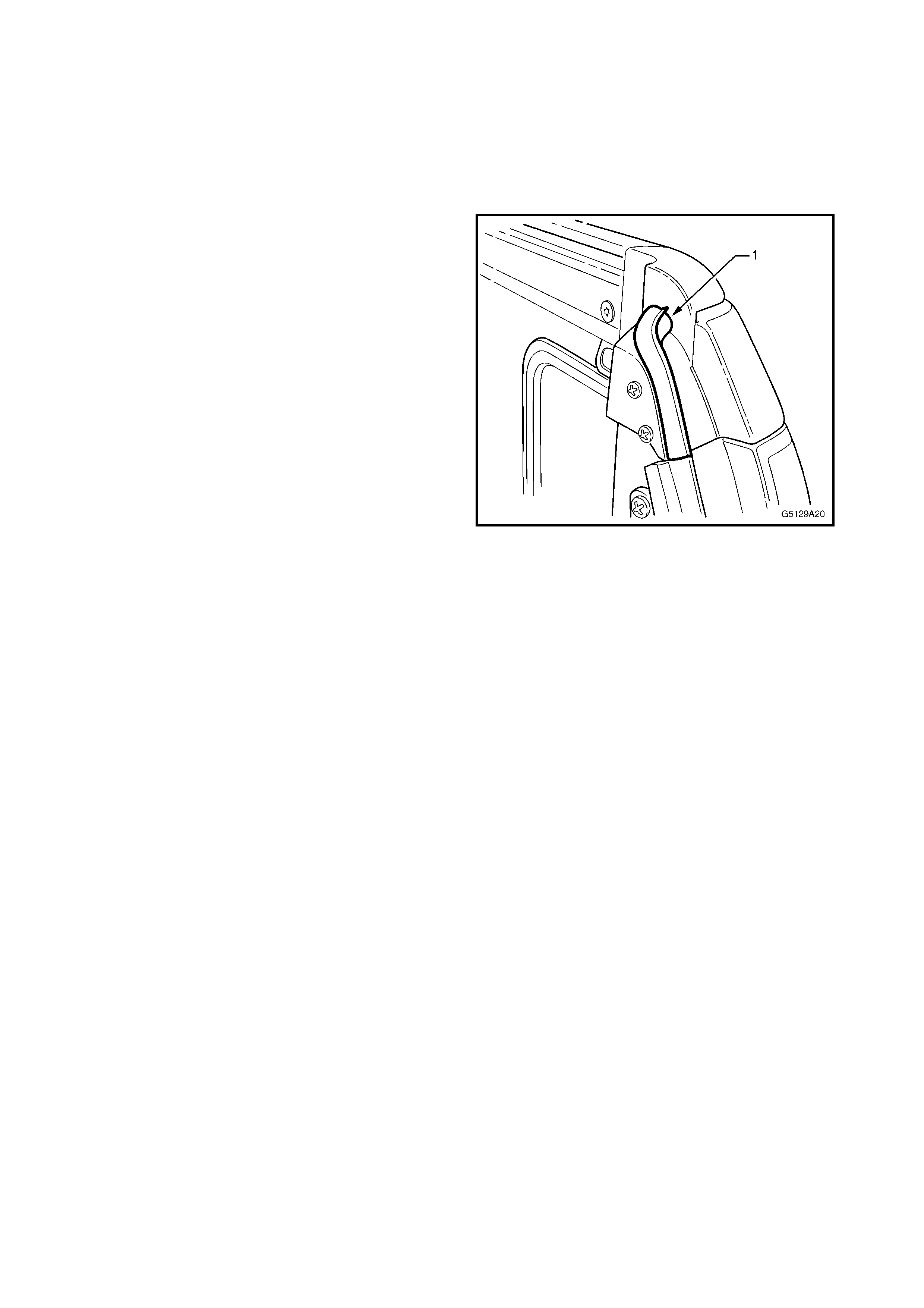
ENDGATE SEALS
NOTE 1: The endgate seals are part of the load
compartment area seal kit, available separately.
NOTE 2: The endgate seals are adhesive backed.
Removal may damage the seals, which must then
be replaced.
REMOVE
1. Open the endgate.
2. Carefully peel the endgate seal (1) from the load
compartment rail end cap.
3. Remove any residual adhesive as required.
REINSTALL
1. Clean the surface of the load compartment rail
end cap with wax and grease remover such as
Prepsol or equivalent.
2. If a new seal is being fitted from the load
com partment area s eal kit, cut the new endgate
seal in half.
3. Remove the backing paper or, if the old seal is
being used, carefully apply contact adhesive
such as Quick-Grip.
4. Fit the seal in position ensuring the lip is facing
rearward and the ends are seated against the
end cap and existing seal, refer Fig. 9A-20.
Figure 9A-20

3.0 TORQUE WRENCH SPECIFICATIONS
Gas strut bracket attaching screw...............................................................................................1.0 – 3.0 Nm
Hinge tongue plate attaching screw............................................................................................1.0 – 3.0 Nm
Tonneau cover hinge tongue screw............................................................................................1.0 – 3.0 Nm
Lock plate attaching screw..........................................................................................................3.0 – 5.0 Nm
Lock plate lock-screw..................................................................................................................1.0 – 3.0 Nm
Gas strut ball screw.....................................................................................................................3.0 – 5.0 Nm
Hinge slot plate screw.................................................................................................................3.0 – 5.0 Nm
Seal plate screw..........................................................................................................................1.0 – 3.0 Nm