
SECTION 7B - HOLDEN SATNAV
IMPORTANT:
Before performing any Service Operation or other procedure described in this Section, refer to Section 00
CAUTIONS AND NOTES for correct workshop practices with regard to safety and/or property damage.
1. GENERAL INFORMATION
There are three models of SATNAV system installed in the Holden Statesman and Caprice WH Series. They are
the: • Philips CARiN 520 (up to August 1999).
• Philips CARiN 522 (August 1999 to August 2000).
• VDO Dayton MS5000 (August 2000 to present).
Thes e sys tems are an option for c ustom ers and are inst alled by Holden Special Vehic les (HSV) at selected sites in
each state.
The Holden SATNAV system employs three technologies:
• The vehicle’s speed signal (from the VSS) and a gyroscope, which is internal to the SATNAV computer.
• Global Positioning System (GPS).
• Digital road map.
Refer to Figure 7B-1. New equipment installed into the vehicle are the:
• SATNAV computer (6).
• SATNAV monitor (3) and escutcheon (4).
• SATNAV GPS antenna (5).
• GPS Interface (7).
• SATNAV remote control and cradle (1) with Holden phone mounting platform (2).
IMPORTANT: The SATNAV equipment installed into W H Series Statesman will differ in appearance between the
different models of navigation system supplied by the vendor.
The following modifications are made to the vehicle to accommodate the SATNAV system:
• Four holes are drilled and countersunk in the lower surface of the radio carrier to provide an attachment
point for the SATNAV monitor.
• The transmission console has the storage compartment cut away to accommodate for the SATNAV monitor
and escutcheon.
IMPORTANT: If either the transmission console or the radio carrier need to be replaced on a SATNAV equipped
vehicle, the templates for making the modifications are available from Holden By Design.
Techline
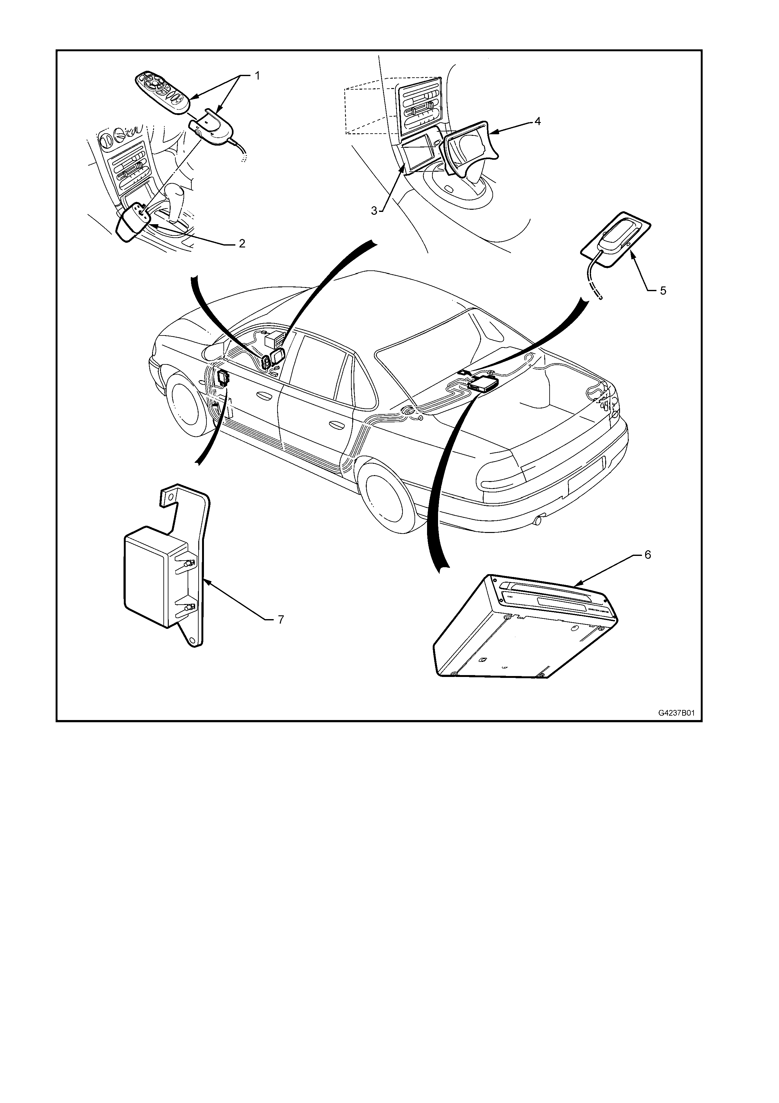
Figure 7B-1

1.1 VEHICLE DIRECTION
The vehicle speed sensor and the gyroscope work together to provide direction and speed signals. These signals
are provided to the SATNAV computer’s processor and are used in conjunction with the GPS to provide vehicle
navigation to the user.

1.2 GLOBAL POSITIONING SYSTEM
The G PS is a s er ies of 27 s atellites which orbit the ear th at an altitude of 21 000 km . The signals from four satellites
must be received by a GPS device to get an accurate three-dimensional position in space and time. If only three
satellites signals are received, only the device’s position in space is attained, and the accuracy is reduced. The
position calculated by the GPS device is accurate to between 30 and 100 metres. GPS reception maybe
interrupted, especially due to the nature of the SATNAV system, in the following instances:
• Between tall buildings.
• In car parks, tunnels or under bridges.
• In forests or avenues.
• During storms.
• In valleys and mountains.
• In the event that the antenna and the position of the satellites are not favourable due to the satellite’s orbit.

1.3 DIGITAL ROAD MAP
The digital road m ap is supplied by VDO Dayton. T he map is contained on a Com pact Disc (CD) which is read by
the SATNAV computer. This CD must be inserted into the SATNAV computer for the system to work. Update
versions of the map are available from VDO Dayton.

1.4 MODEL IDENTIFICA TION
PHILIPS CARIN 520
Philips CARiN 520 system is identifiable by the brand labelling on the computer fitted to the vehicle, refer to
Fig 7B-3. The monitor fitted has a smaller screen than other models and an escutcheon to suit. Refer to item 6 in
Fig 7B-7. The remote control is not equipped with a ‘MAP’ button.
In operation, this system mutes the audio system when giving the voice commands through the audio system
speakers.
PHILIPS CARIN 522
The Philips CARiN 522 has the same computer as the Philips CARiN 520. The monitor is a large monitor with a
dark grey escutcheon. The remote control has a ‘MAP’ button.
VDO DAYTON MS5000
The VDO Dayton is the current system installed. The computer is different to the two previous systems. The
labelling on the computer identifies it as the VDO Dayton 5000. Refer to Fig 7B-4. The m onitor and remo te control
are the same as the Philips CARiN 522.

1.5 GENERAL OPERATION
NOTE: For a detailed version of operation of the SATNAV system, refer to 2. OPERATING INSTRUCTIONS for
the user manual pertinent to the system fitted to the vehicle.
The SATNAV system works in the following manner:
• Initially, with power s upplied, the SATNAV monitor tur ns on and the system ac quire s a G PS s ignal. T his will
give a position in space within 30 to 100 metres. This position will be translated onto the digital road map
and shown on the monitor. The vehicle may not be shown in its exact position yet, as the system m ay not
be calibrated.
• The user can now enter a destination using the f unctions of the system . T he rem ote control, which can be
used while in its cradle or pointed at the screen, is used to navigate the various screens. The m ap screen
will highlight the route to be taken.
• The system will start to calibrate itself as soon as the vehicle moves. The VSS provides electrical pulses,
which are converted into dis tance, and the gyroscope will detect and measure any change in direction. The
GPS signal will continue to be received and used as a reference by the system.
• Once the vehicle is calibrated, it will be represented by the arrow being shown on the map in the correct
position and travelling in the correct direction. To get to this stage it may take one or two changes of
direction of the vehicle. The system will supply audio com mands during this time fo r any direction c hanges
required. These audio commands are given through the front left-hand instrument panel and door speaker.
• If at any stage a recommended turning point is not taken by the driver, the SATNAV system will calculate an
alternate route.
There are some important features that should be mentioned about the system:
• Calibration will take longer if the vehicle is driven along a straight road for some distance.
• The vehic le’s pos ition is stor ed af ter the vehic le is tur ned of f . The system requir es 30 sec onds to s hut down
properly.
• If the vehicle’s position has been stored previous ly, the system will work without GPS reception and still be
accurate.
• The vehicle’s position will remain in memory after the battery has been disconnected, but only if the
SATNAV system has been allowed 30 seconds to shut down properly.

1.6 GENERAL DESCRIPTION
For the following description, refer to Figure 7B-2. The Holden SATNAV system is based on a either the Philips
CARiN or VDO Dayton Navigation Systems with the following changes:
• The main harness is supplied by HSV.
• A GPS Interface (6) is also supplied by HSV and installed to provide extra features for the SATNAV
systems.
GPS INTERFACE
The GPS Interface is installed underneath the left-hand instrument panel end cap cover. The GPS interface
provides these features for the following SATNAV systems:
PHILIPS CARIN 520
• A ten s ec ond timer that keeps the s ystem active during the loss of power when the vehicle is s witched f r om
ACC to IGN.
• A speed signal buffer.
• Converts the SATNAV computers mute signal polarity.
• Mutes all of the audio system when the SATNAV computer gives a voice command.
PHILIPS CARIN 522
• A ten s ec ond timer that keeps the s ystem active during the loss of power when the vehicle is s witched f r om
ACC to IGN.
• A speed signal buffer.
• A switching r elay for the front lef t-hand side speakers . T his s witches the s peakers f rom the audio s ystem to
the SATNAV system. Af ter the SATNAV system has completed the voice com mand the GPS interface will
switch the speakers back the audio system.
VDO DAYTON MS5000
• A speed signal buffer.
• A switching r elay for the front lef t-hand side speakers . T his s witches the s peakers f rom the audio s ystem to
the SATNAV system. Af ter the SATNAV system has completed the voice com mand the GPS interface will
switch the speakers back the audio system.
SATNAV EQUIPMENT LAYOUT
The SAT NAV harness (4) is installed from the SATNAV com puter (1) in the rear com partment, down the left-hand
side of the vehicle under the inner rocker panel cover. At the shroud lower trim assembly left-hand side, the harness
splits and is routed to the GPS interface. There are three harness extensions from the GPS interface:
• The SATNAV Harness Vehicle Speed Sensor (VSS) connector for V6 equipped vehicles is routed to the
PCM (5).
• The SATNAV Harness VSS connector for GEN III V8 equipped vehicles is routed to the rear of the
instrument cluster.
• The SATNAV Harness cellular phone connector (7) is routed to the cellular phone connection behind the
left-hand side centre fascia side extension.
• The SATNAV Harness radio patch connector (8) is routed to its connection at the rear of the radio/CD.
At the rear of the vehicle, the SATNAV light patch harness connects the SATNAV harness between the body
harness and the right-hand rear quarter lamp harness (2). This provides the system with the following necessary
inputs:
• Reverse light operation.
• Tail light operation.
The light patch harness has a connector (12) joining it to the SATNAV harness, which is located in the channel
under the rear parcel shelf in the rear compartment.
The system is earthed (3) at the left-hand gas strut mounting bracket in the rear compartment.
• The MS5000 system is supplied with the following components:
• SATNAV computer (1) which is mounted under the rear parcel shelf in the rear compartment.
• SATNAV monitor ( 10), which is ins talled in the c entre fascia as s embly. The harness for the monitor (4) runs
from the computer, down the left-hand side of the vehicle, to the monitor.
• SATNAV remote control and cradle assembly (8) is installed on the centre console adjacent to the
passenger. The remote control harness runs from the computer, down the left-hand side of the vehicle to
the remote control cradle.
• GPS antenna (11) is installed under the rear parcel shelf trim.
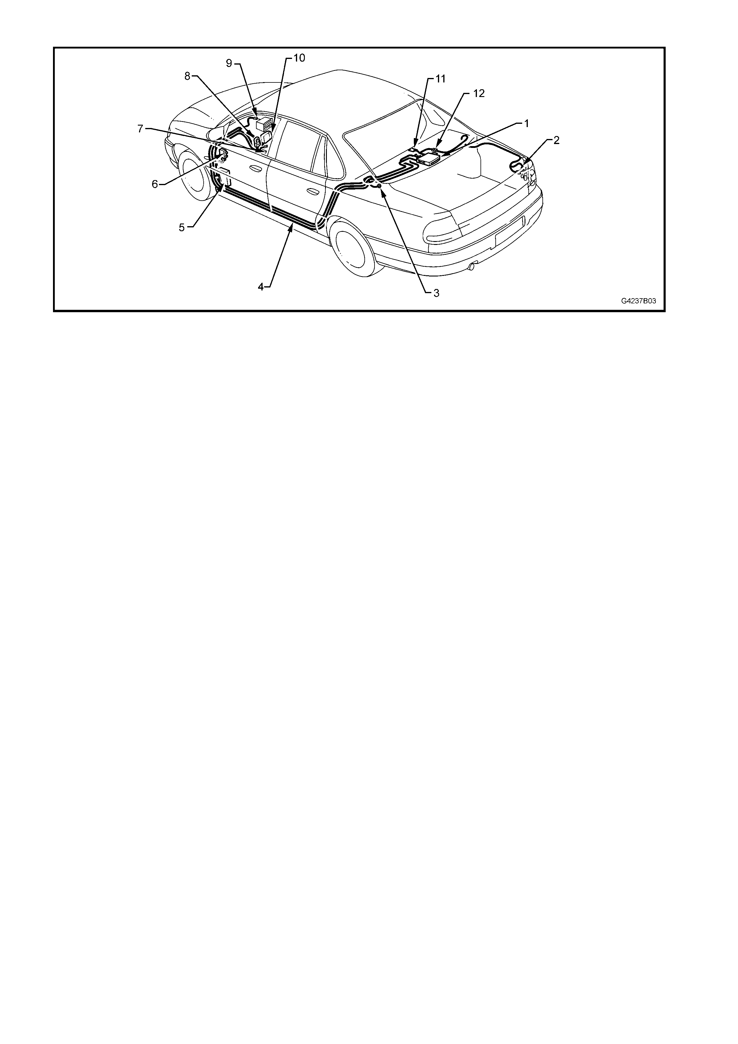
Figure 7B-2

2. OPERATING I NSTRUCTI ONS
The Holden SATNAV system is supplied by VDO Dayton. Due to software upgrades by VDO Dayton, the most
current user manual pertaining to the Holden SATNAV system is available from the VDO Dayton web site.
2.1 CARIN USER MANUAL
The CARiN User Manual has been reproduced and transferred into this package. To view the manual, refer to
Section 4L.
IMPORTANT: This manual should have been supplied with the CARiN Navigation System. VDO Dayton is the
technical authority on this equipment.

2.2 VDO DAYTON MS5000 USER MANUAL
DOWNLOAD
On your computer, open a web browser. This is usually Netscape Navigator or Microsoft Internet Explorer.
1. At the browsers address bar, type in the following:
http://www.vdodayton.com/products/navigation/products/ms_5000.htm
2. Left click on the button ‘Download User Manual.
3. Right click on ‘Great Britain’ and select ‘Save Target As….’.
4. Select a directory you wish to save the file to and left click on ‘Save’. The computer will inform you when the
download is complete.
VIEWING
1. Using Windows Explorer, navigate to the directory where the VDO Dayton MS5000 User Manual is stored.
2. Double click with the left button on the file. This will open the file in Adobe Acrobat® Reader.
NOTE: There may be more than one language contained in the VDO Dayton Instruction Manual. Scroll forward to
the relevant section.
3. SERVICE OPERATIONS
To as sist in the diagnosis, rem oval and installation of SATNAV system com ponents, electrical wiring diagrams and
connectors are located in 5. WH SATNAV WIRING DIAGRAMS.
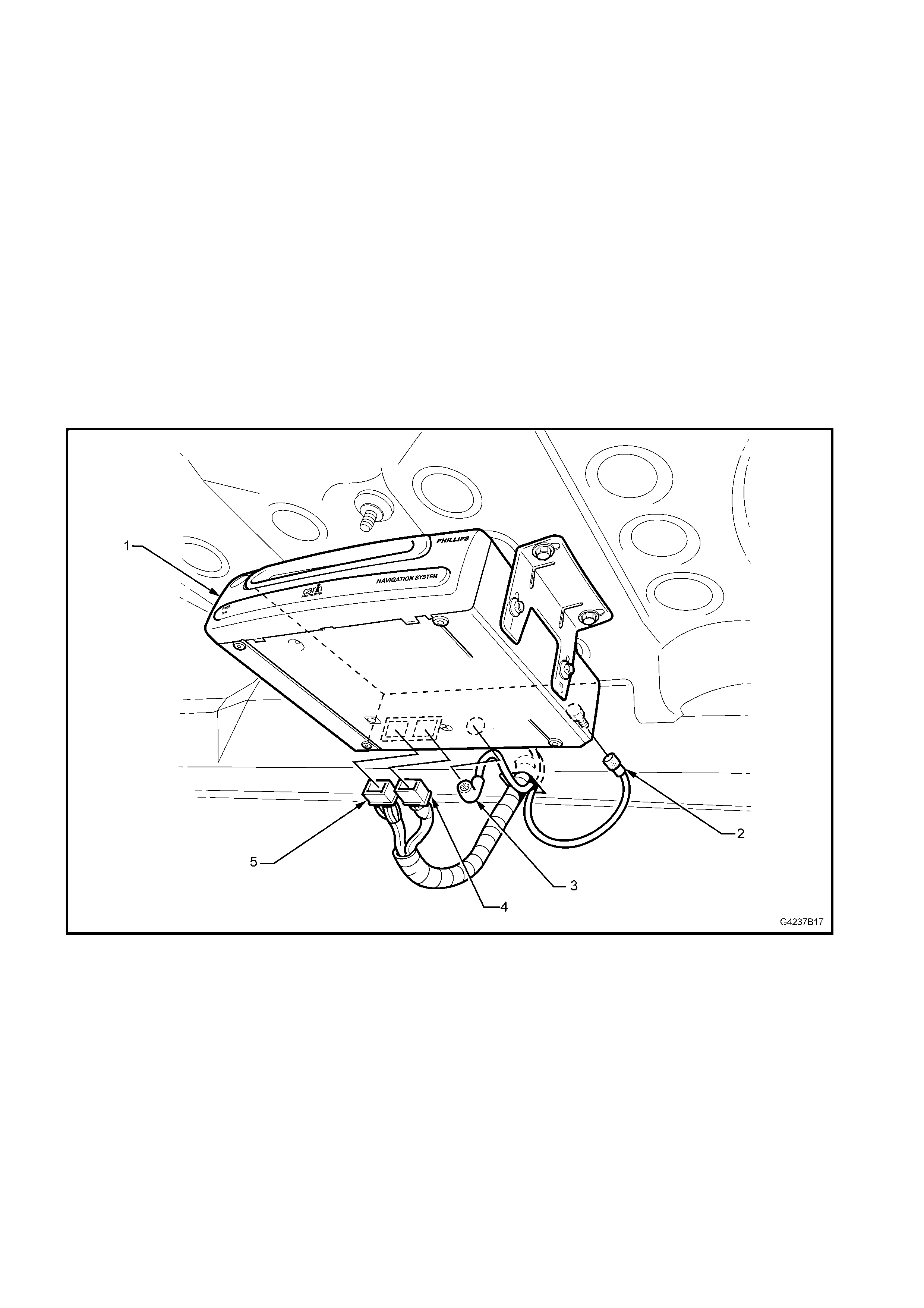
3.1 SATNAV COMPUTER
REMOVAL (PHILIPS CARIN)
1. Open the rear compartment. Disconnect the following from the SATNAV computer (1):
• Remote control harness connector (5).
• SATNAV harness connector (4).
• GPS antenna connector (2).
• SATNAV monitor harness connector (3).
2. Remove the bolts from the brackets securing the SATNAV computer to the underside of the parcel shelf and
remove the computer.
REINSTALL (PHILIPS CARIN)
Installation is the reverse of the removal procedure.
Figure 7B-3
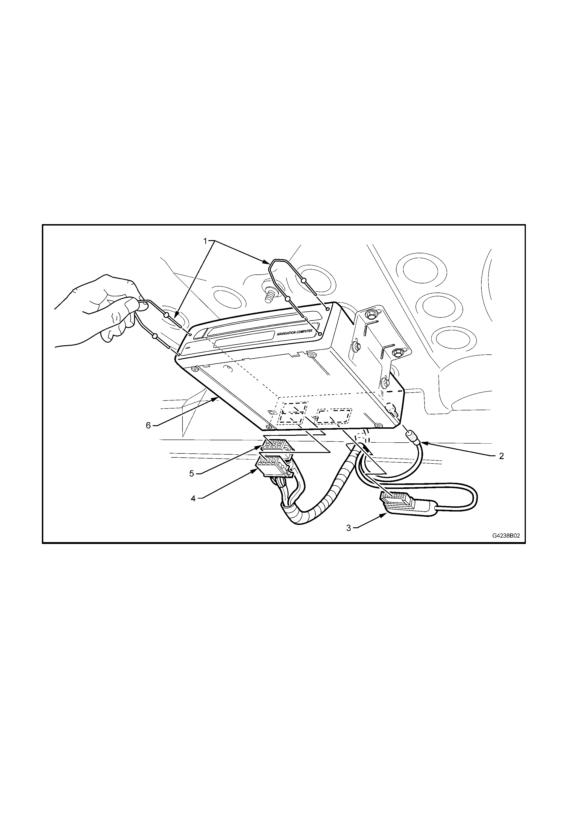
REMOVE (VDO DAYTON MS5000)
The SATNAV computer is located in the rear compartment. It is mounted inside a metal carrier, which is in turn
attached to the parcel shelf by brackets.
1. Open the rear compartment. Disconnect the following from the SATNAV computer:
• Remote control harness connector (5).
• SATNAV harness connector (4).
• GPS antenna connector (2).
• SATNAV monitor harness connector (3).
2. Using the SATNAV computer removal tool (1), carefully pull the computer out of the metal carrier (6). The
SATNAV computer removal tool can be obtained from VDO Dayton or alternatively, the radio/CD removal tool,
service tool 179 1308 0000, can be used.
REINSTALL (VDO DAYTON MS5000)
Installation is the reverse of the removal procedure.
Figure 7B-4
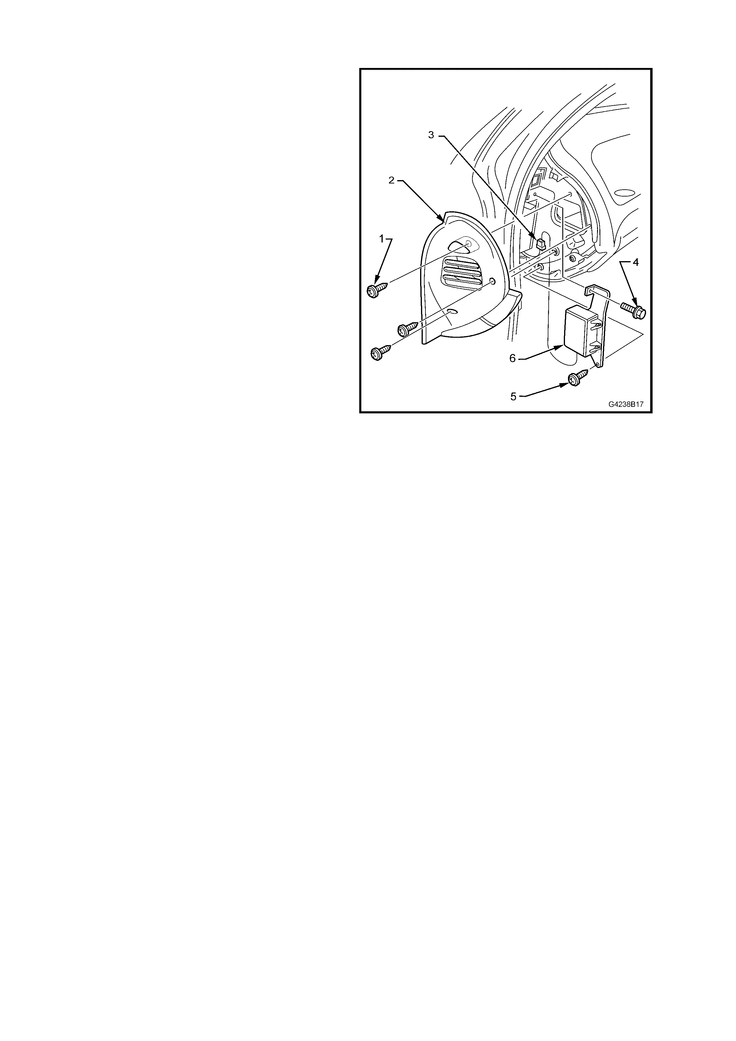
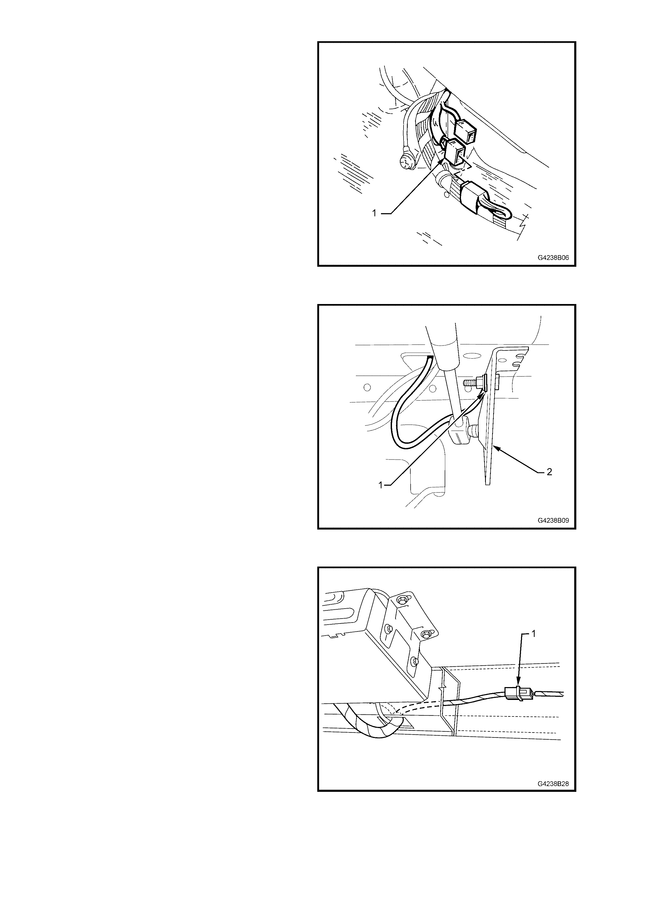
3.2 GPS INTERFACE
The GPS interface is installed under the left-hand
instrument panel end cap.
REMOVE
1. Open the left-hand side front door.
2. Remove the three screws (1) securing the
instrument panel end cap cover (2) and remove
the cover.
3. Disconnect the GPS interface connector (3).
4. Remove the hex head screw (4) and screw (5).
5. Remove the interface (6).
REINSTALL
Installation is the reverse of the removal procedure.
Figure 7B-5
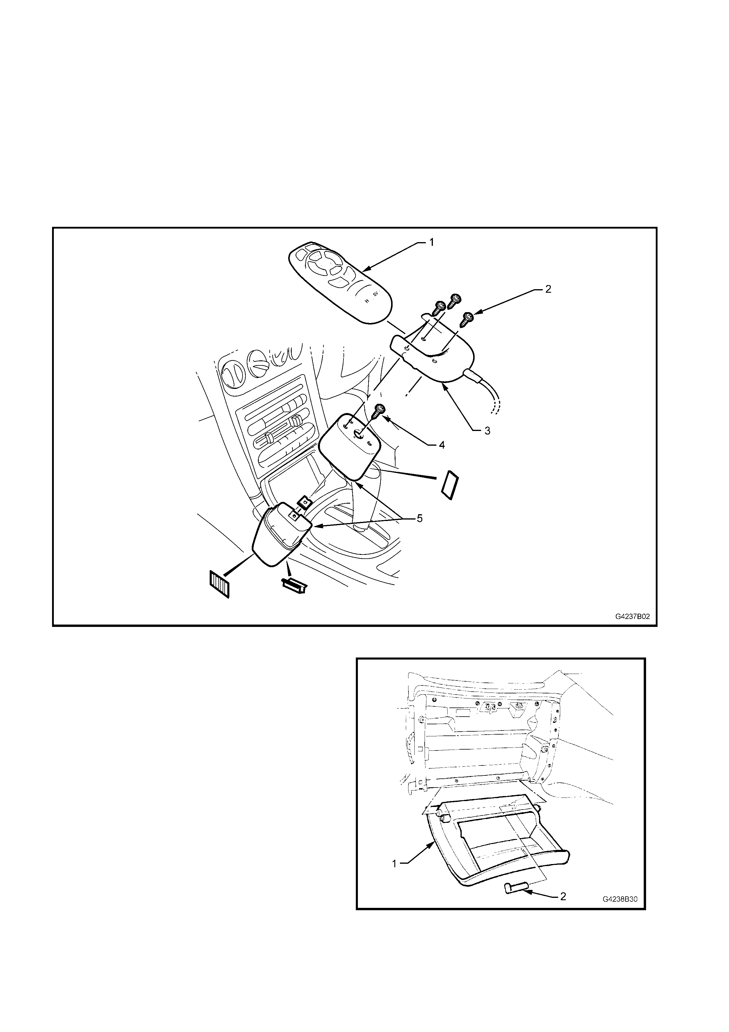
3.3 SATNAV REMOTE CONTROL CRADLE
The SATNAV remote control is located adjacent to the transmission selector on the centre console. The remote
controls between the three m odels of SAT NAV systems vary, however, the removal and ins tallation procedur es are
identical for all three.
REMOVE
1. Remove the SATNAV remote control (1) from the cradle (3).
2. Remove the three screws (2) securing the remote control cradle to the mobile phone mounting platform (5).
Place the cradle on the floor ensuring that the cable is not placed under any stress.
3. Remove the screw (4) securing the two halves of the phone mounting platform and remove the platform.
Figure 7B-6
4. Open the instrument panel lower compartment
(1) and lever out the hinge pin (2) on the right-
hand side. Lower the compartment and
withdraw the pin. Disengage the travel limit
pegs by tilting the compartment.
Figure 7B-7
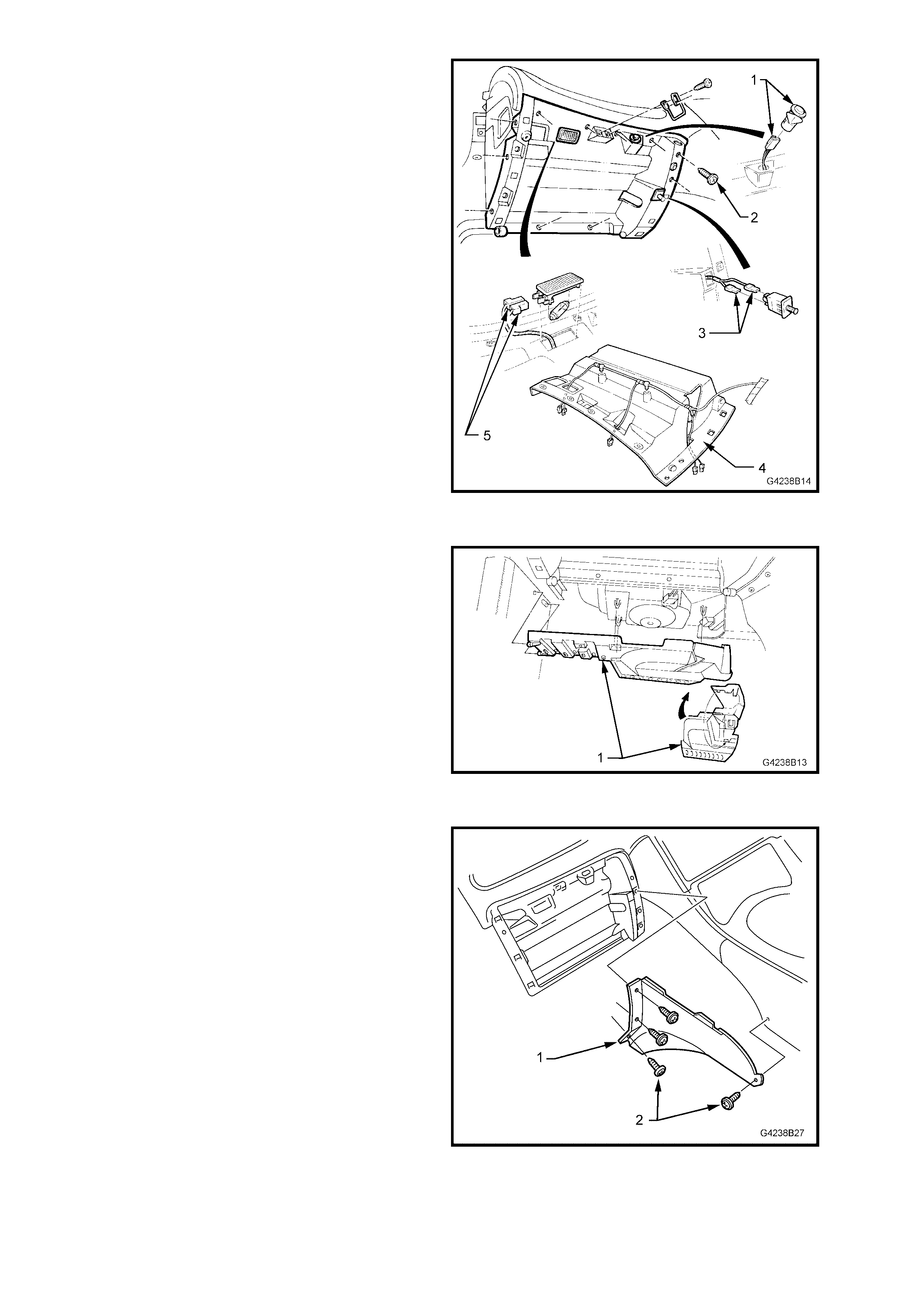
5. Remove the 11 retaining screws (2) from the
instrument compartment roof (4).
6. Disconnect the instrument panel lamp
connectors (5), rear compartment lock switch
connector (1), instrument panel switch
connectors (3) and unclip instrument panel
compartment wiring harness.
7. Remove the instrument compartment roof.
Figure 7B-8
8. Unclip the duct cover flap on the right-hand
side of the f ootwell upper closing panel left side
(1).
9. Disengage the locating lugs to passenger side
shroud lower trim assembly and grab the
closing panel firmly and detach by pulling the
left side down first. Disengage the right side
clip and remove the panel.
Figure 7B-9
10. Remove the four screws (2) securing the
centre fascia side extension (1) in place.
Remove the extension.
11. Disconnect the remote control cradle from the
remote control harness.
REINSTALL
Installation is the reverse of the removal procedure.
Figure 7B-10
3.4 SATNAV MONITOR
The SAT NAV monitor assembly is installed in a m odified instrument centre fascia. The two models of monitor that
have been fitted to the WH Series are removed and installed in the same way.
REMOVE
1. Remove the SATNAV monitor harness
connector from the back of the SATNAV
computer.
Refer to Fig 7B-3, item 3, for Philips CARiN
systems. Refer to Fig 7B-4, item 3, for VDO
Dayton MS5000 systems.
2. Move the front passenger seat all the way to
the rear.
3. Remove the footwell upper closing panel left
side, refer to 3.5 SATNAV HARNESS
ACCESS FITTINGS.
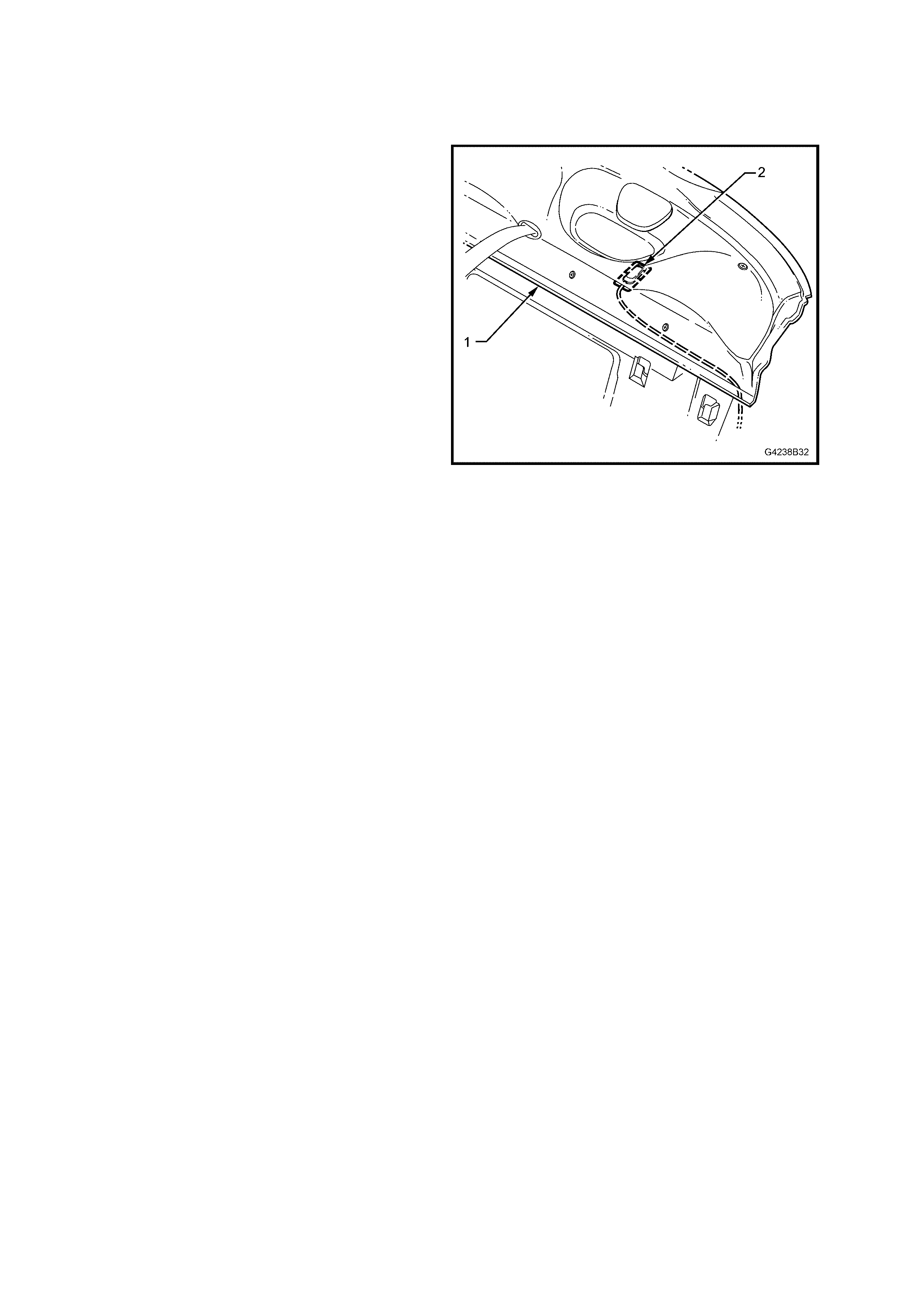
4. Unhook the excess antenna lead (2) coiled
through the clip (1) on the right-hand side of the
instrument carrier rail.
Figure 7B-11
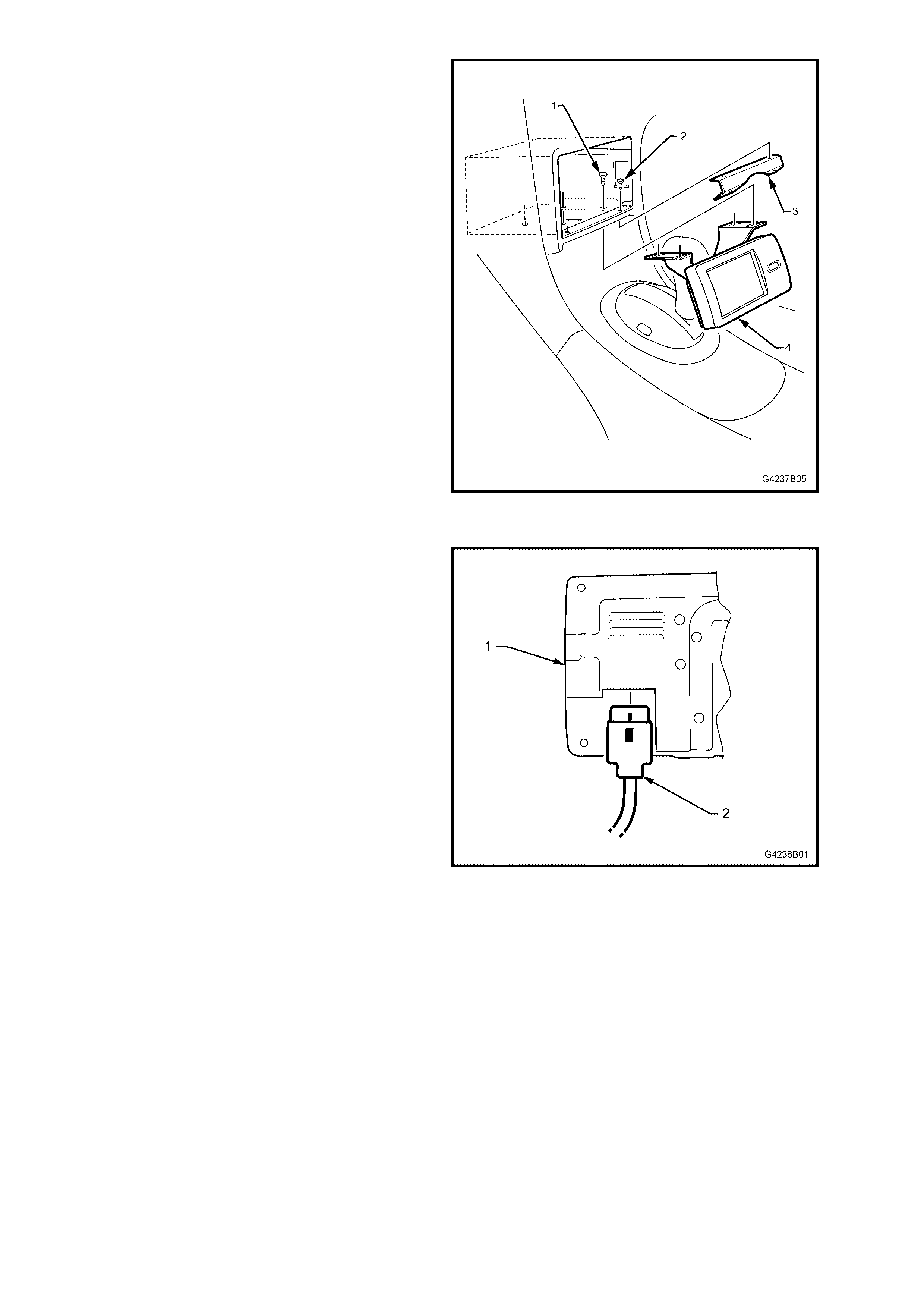
IMPORTANT: For vehic les equipped with Philips CARiN system s, the m onitor escutcheon m ay be attached on the
lower side to the transmission console with double-sided tape.
5. Remove the two screws (2) securing the monitor escutcheon (3) to the monitor escutcheon mounting bracket
(1). Remove the monitor escutcheon.
6. Place the gear selector in the ‘2’ position.
7. Carefully prise out the transmission console (4), disconnecting the power window switch assy (5) and console
bin lamp harness where fitted. Remove the transmission console.
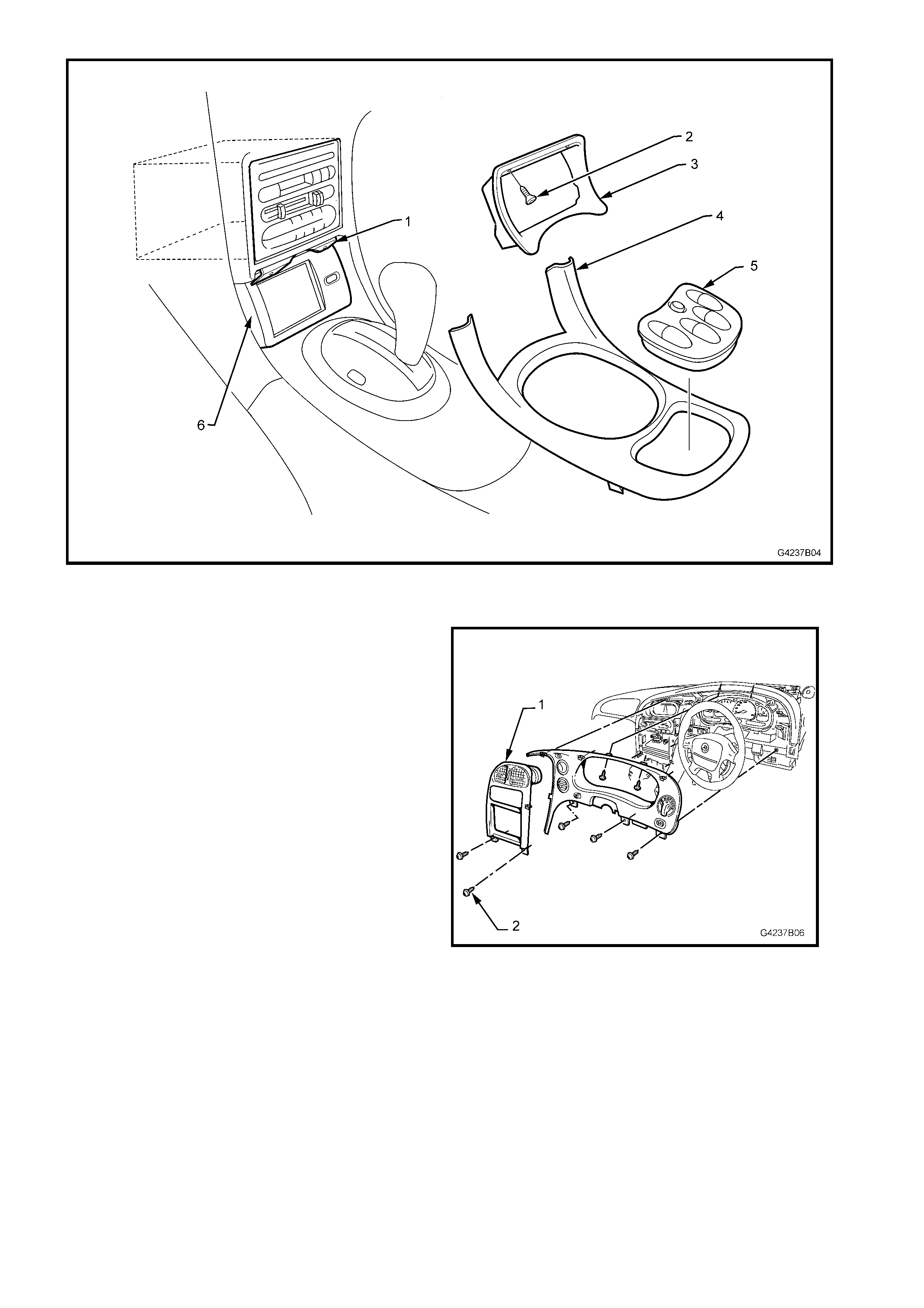
Figure 7B-12
8. Remove the two screws (2) and pull the
instrument fascia escutcheon (1) from the
retaining clips.
Figure 7B-13
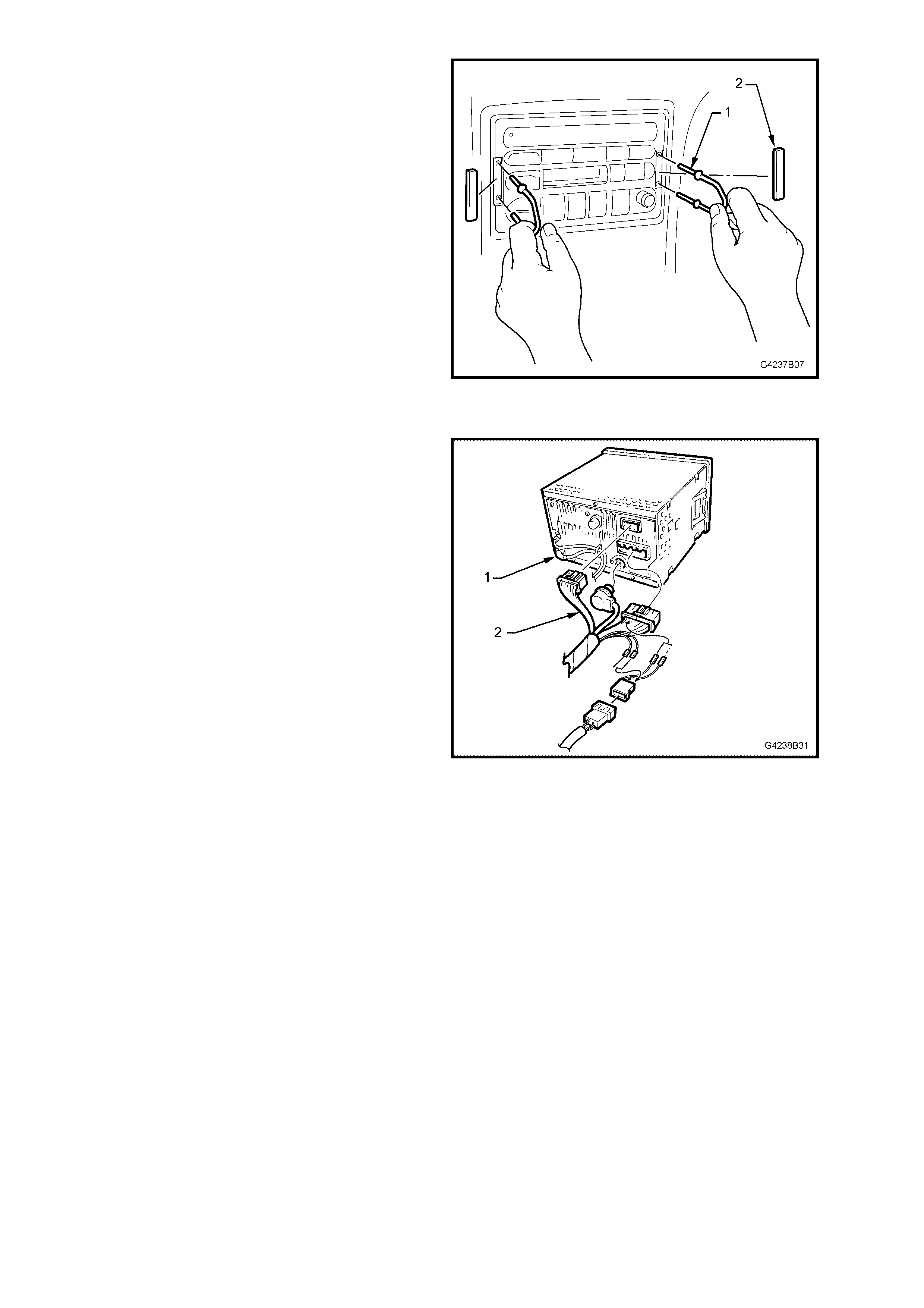
9. Remove the service tool hole covers (2) and
remove radio/cassette/CD from the instrument
panel using the service tool 179 1308 0000 (1).
Figure 7B-14
10. Disconnect the radio/CD harness and CD
connector (2), if fitted. Disconnect the antenna
and diversity antenna (1) if fitted.
Figure 7B-15
11. Remove the two screws (2) that secure the
monitor escutcheon mounting bracket (3) and
remove the bracket.
12. Remove the four screws (1) securing the
monitor assembly (4) in place.
Figure 7B-16
13. Remove the monitor assembly, disconnecting
the SATNAV monitor harness connector (2)
from the rear of the monitor (1).
Figure 7B-17
REINSTALL
Installation is the reverse of the removal procedure. Where the monitor escutcheon has been secured to the
transmission c onsole with double- s ided tape, r emove the old tape. Clean both m ating s ur f ac es and attac h new tape
before installing the monitor escutcheon.
3.5 SATNAV HARNESS ACCESS FITTINGS
There ar e three separate harnesses for the SATNAV s ystem running from the rear com partm ent to the front of the
passenger compartment, up behind the instrument panel.
REMOVE
1. Remove the SATNAV remote control cradle,
refer to 3.4 SATNAV REMOTE CONTROL
CRADLE.
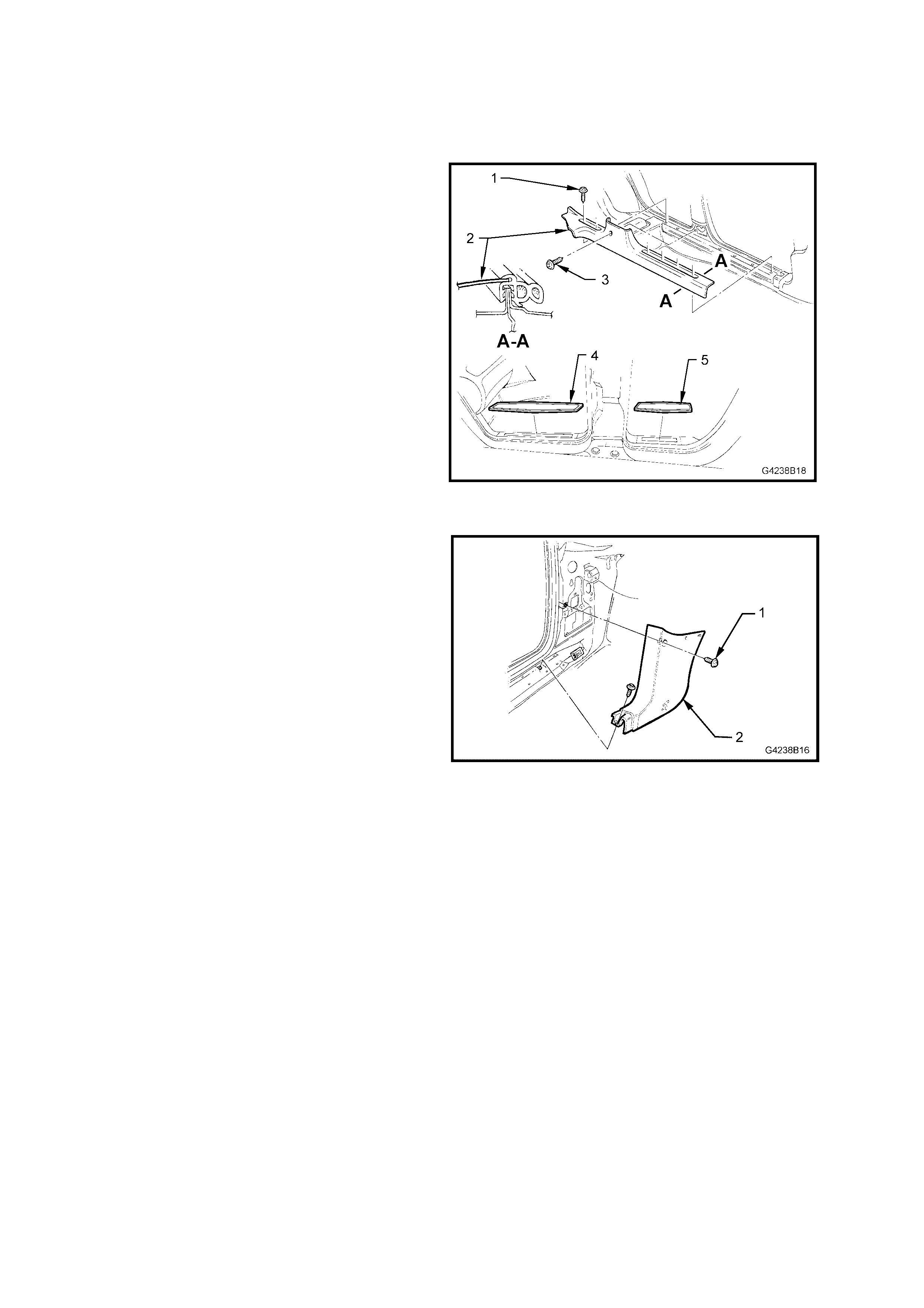
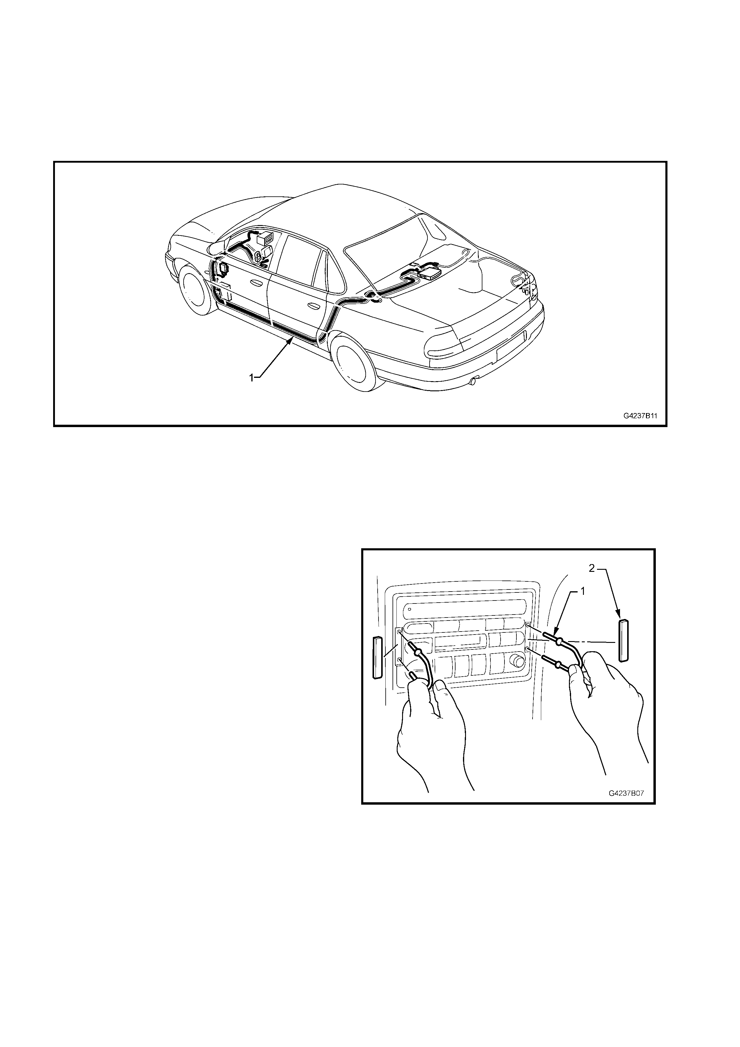
2. Remove the rocker panel cover inserts (4 and
5) and the rocker panel cover retainer screws
(1 and 3) from the rocker panel. Remove the
cover assembly (2).
Figure 7B-18
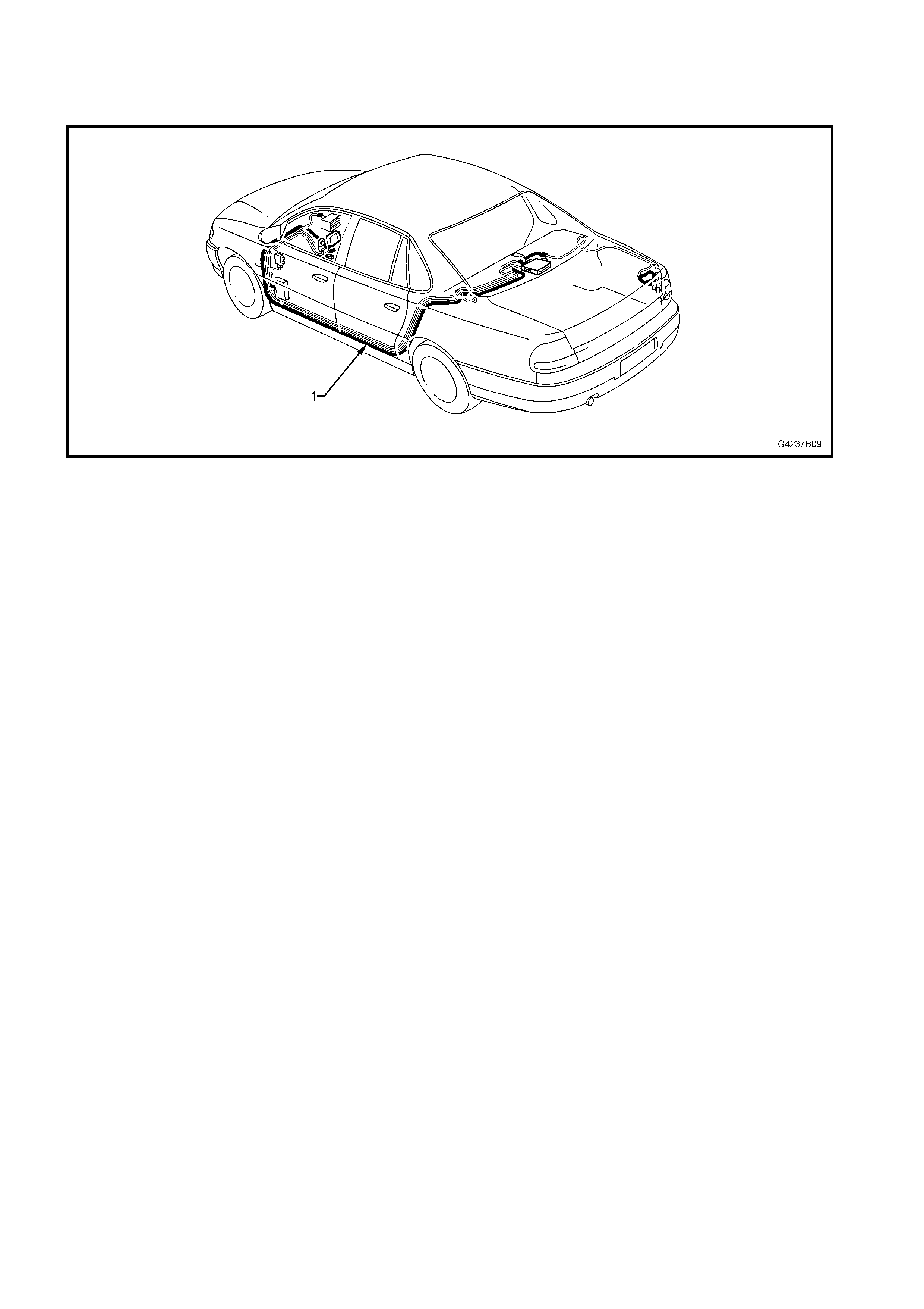
2. Remove the upper retaining screw (1) and the
screw beneath the rocker panel cover securing
the shroud lower trim assembly (2) to the
rocker panel.
3. Pull the shroud lower trim assembly rearward
from the retainer, removing the assembly.
4. Remove the rear seat and the left-
hand cushion. Refer to Section 1A7,
2.8 REAR SEAT CUSHION AND BACK
ASSEMBLIES.
Figure 7B-19
REINSTALL
Installation is the reverse of the removal procedure.
3.6 SATNAV GPS ANTENNA
The SATNAV GPS antenna is located under the rear parcel shelf trim.
REMOVE
1. Disconnect the GPS antenna from the rear of
the SATNAV computer. For Philips CARiN
systems, refer to Fig 7B-3, item 2. For VDO
Dayton MS5000 systems, refer to Fig 7B-4,
item 2.
2. Remove the rear seat and the left-
hand cushion. Refer to Section 1A7,
2.8 REAR SEAT CUSHION AND BACK
ASSEMBLIES.
3. Remove the rear parcel shelf trim (1) to gain
access to the antenna (2).
4. Carefully pull the antenna cable through from
the rear compartment and remove the antenna.
Figure 7B-20
REINSTALL
Installation is the reverse of the removal procedure.
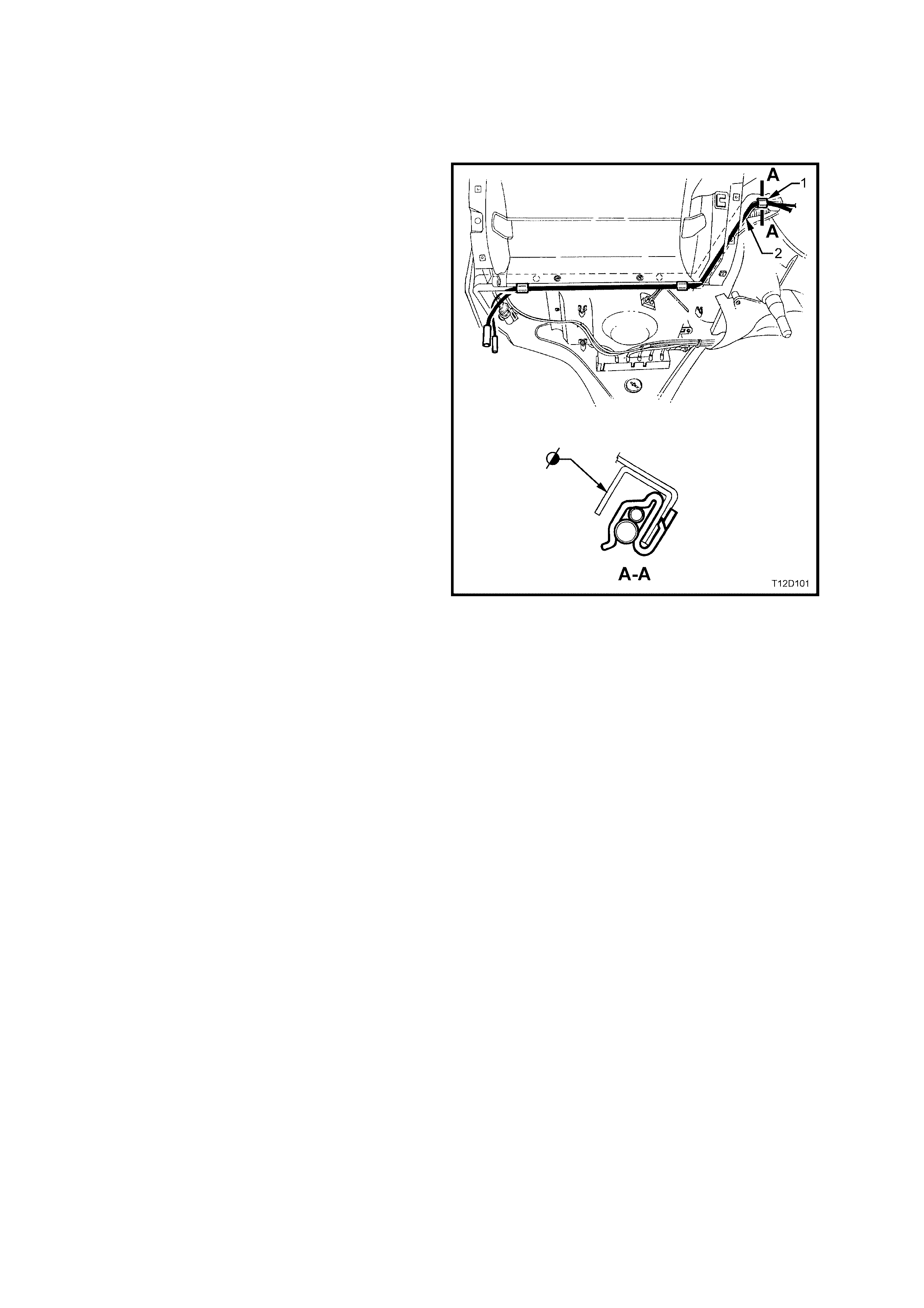
3.7 SATNAV HARNESS
The VDO Dayton MS5000 SATNAV and remote control harnesses are joined by two wires at the SATNAV
computer. If the SATNAV harness (1) is being removed separately, the wires connecting the two harnesses must
be disconnected.
The SATNAV harness has two variants. The VSS (Vehicle Speed Sensor) is connected to the instrument cluster
connector for vehicles equipped with GEN III V8 engines. The VSS for V6 equipped vehicles is connected at the
PCM.
Figure 7B-21
REMOVE
1. Remove the trim and fittings, refer to 3.5 SATNAV HARNESS ACCESS FITTINGS.
2. Remove the transmission console and the centre fascia escutcheon, refer to 3.4 SATNAV MONITOR.
3. Remove the service tool hole covers (2) and
remove radio/cassette/CD from the instrument
panel using the service tool 179 1308 0000 (1).
Figure 7B-22
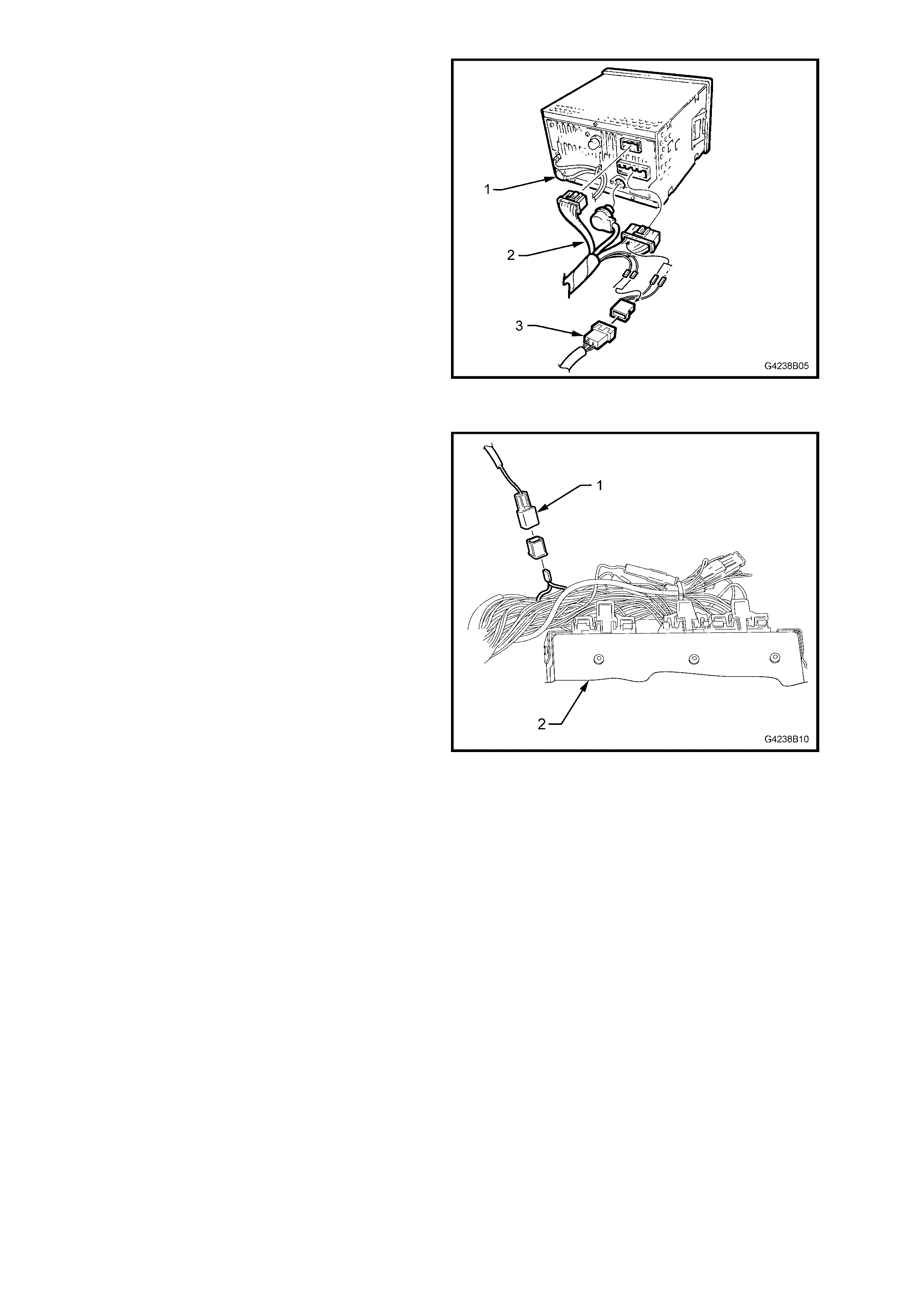
4. Disconnect the radio/CD harness and CD
connector (2), the antenna and diversity
antenna and the radio/CD patch harness
connector (3) from the radio/CD harness.
Figure 7B-23
5. For V6 and V6 supercharged vehicles:
a. Disconnect the VSS connector (1) at the
powertrain harness adjacent to the PCM
(2).
Figure 7B-24
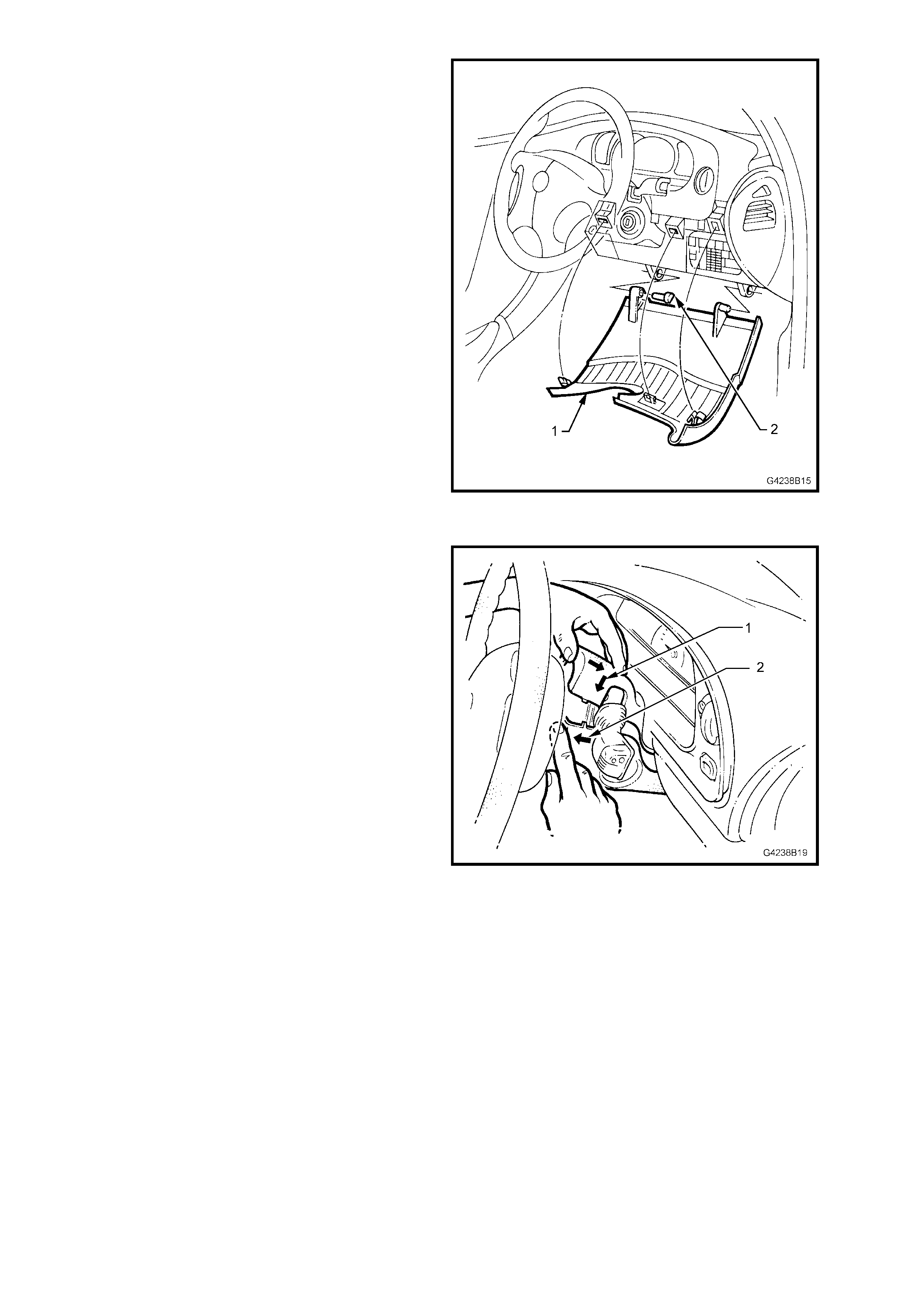
6. For GEN III V8 vehicles:
a. Adjust steering wheel to the uppermost
position. F irmly grasp the right-hand s ide of
the lower cover panel (1) firmly and pull
towards the rear of the vehicle. Repeat the
procedure for the left side of the cover.
Prise out the lef t-hand hinge pin (2) using a
flat blade screwdriver. Tilt the cover down
on the left-hand side and disengage the
right hinge pin and remove the panel.
Figure 7B-25
b. Remove the screw from under side of the
lower steering column cover.
c. Remove the upper (1) and lower (2)
steering column covers.
Figure 7B-26

d. Remove the screws (1) retaining the
instrument fascia (2) and pull the fascia
from the retaining clips.
NOTE: Care must be taken to disconnect the
headlamp switch connector, fog lamp switch
connector (if fitted), trip computer switch connector
(if fitted), clock and hazard switch connector from
the main harness.
Figure 7B-27
e. Remove the two screws (1) securing the
instrument cluster (3) to the instrument
panel.
f. Pull instrument cluster out, disconnecting
the instrument connector (2) from the rear.
Guide the cluster out between the
instrument panel pad and the steering
wheel.
Figure 7B-28
g. Disconnect the VSS connector from the
main wiring harness at the instrument
cluster connector (1).
Figure 7B-29
7. Disconnect the SATNAV Harness cellular
phone connector (1) from behind the left-hand
centre fascia extension.
8. Disconnect the GPS Interface connector but
do not remove the interface. Refer to
3.2 GPS INTERFACE.
Figure 7B-30
9. Disconnect the SATNAV harness earth
terminal (1) from the rear compartment gas
strut mounting bracket (2).
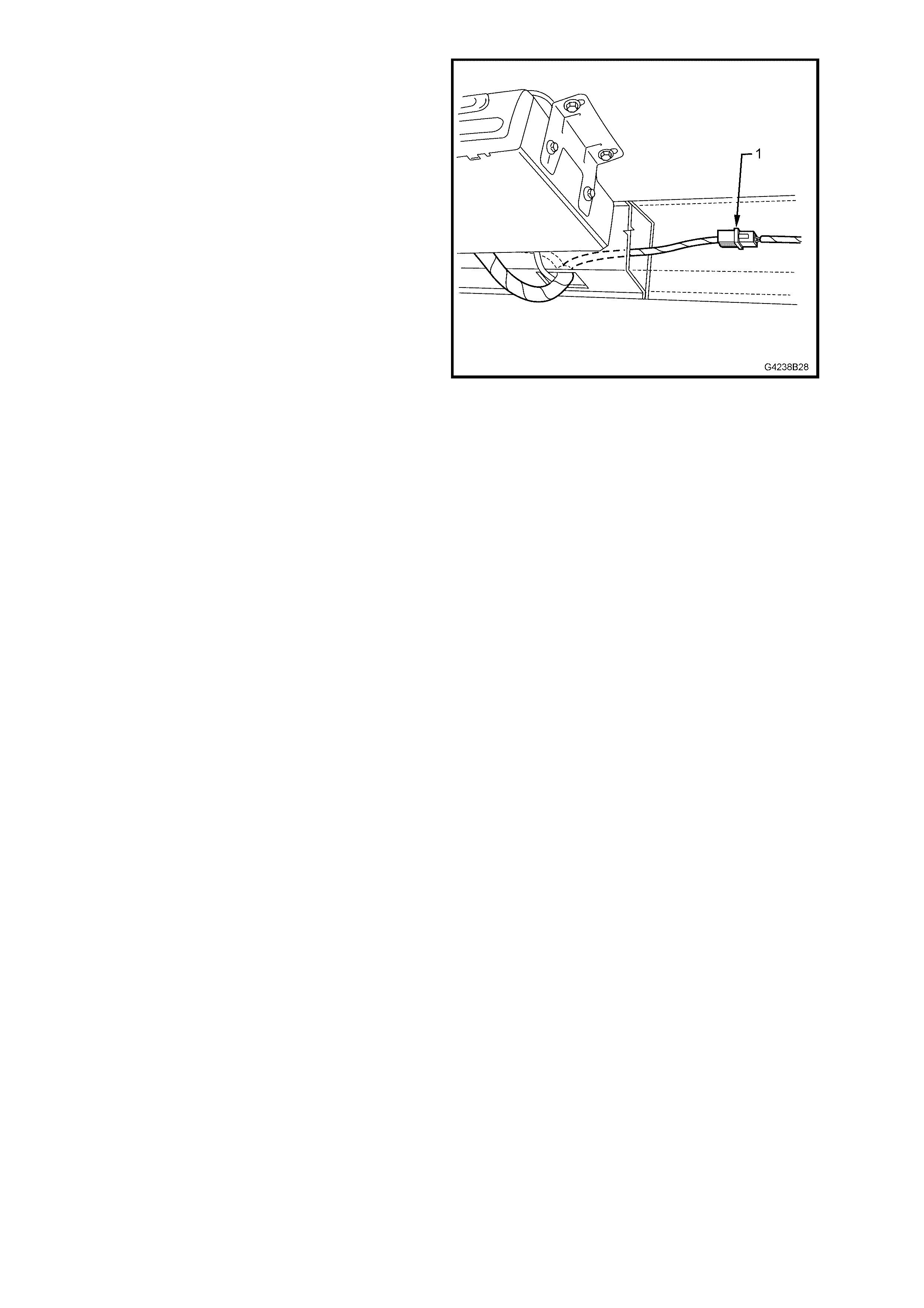
Figure 7B-31
10. Pull the SATNAV light patch harnes s connector
(1) out of the channel and disconnect.
REINSTALL
Installation is the reverse of the removal procedure.
Figure 7B-32

3.8 SATNAV REMOTE CONTROL HARNESS
The SATNAV remote control harness (1) runs from the computer located in the rear compartment to the remote
control cradle next to the driver.
Figure 7B-33
REMOVE
1. Remove the trim and fittings, refer to 3.5 SATNAV HARNESS ACCESS FITTINGS.
2. If the remote control harness is being removed only:
a. Remove the rem ote c ontrol har nes s c onnec tor and the SATNAV harness connector fr om the computer . For
Philips CARiN systems, refer to Fig. 7B-3, items 4 and 5. For VDO Dayton systems, refer to Fig. 7B-4,
items 4 and 5.
b. For VDO Dayton MS5000, remove the speaker wires, blue (pin 5) and blue/green (pin 6) of the remote
control harness connector (YR58). Refer to 5.2 WH STATESMAN WIRING DIAGRAM or
5.5 WH CA PRICE WIRING DIAGRAM depending on what model vehicle is being worked on.
3. Remove the remote control harness.
REINSTALL
Installation is the reverse of the removal procedure.
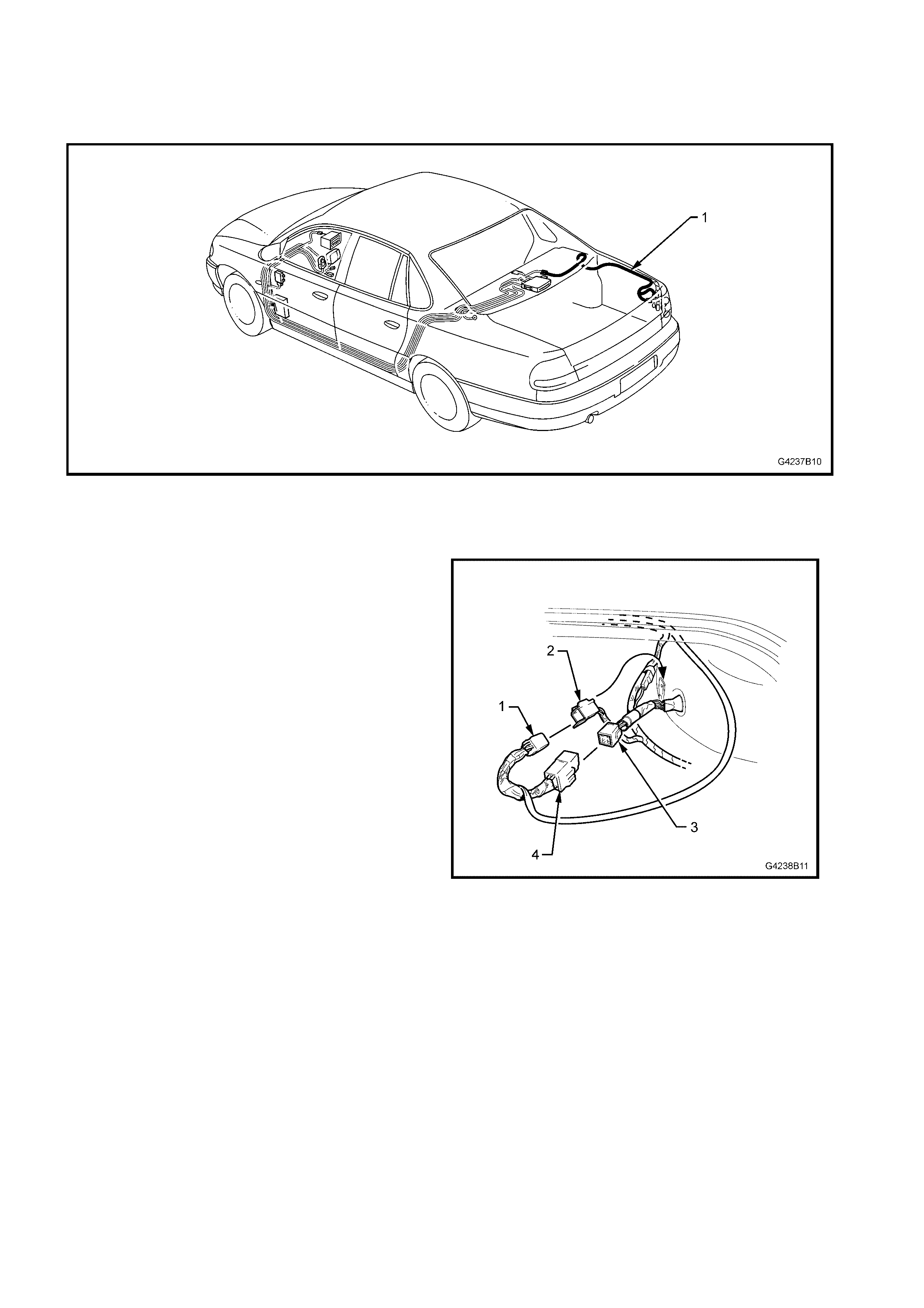
3.9 SATNAV MONITOR HARNESS
The SATNAV monitor harness (1) runs from the computer in the rear compartment to the rear of the monitor
installed in the centre fascia assembly.
Figure 7B-34
REMOVE
1. Remove the trim and fittings, refer to 3.5 SATNAV HARNESS ACCESS FITTINGS.
2. Remove the SATNAV monitor, refer to 3.3 SATNAV MONITOR.
3. Rem ove the SATNAV monitor harness connector from the rear of the computer and remove the harness. For
CARiN installations, refer to Fig 7B-3, item 3. For VDO installations, refer to Fig 7B-4, item 3.
REINSTALL
Installation is the reverse of the removal procedure.
3.10 SATNAV LIGHT PATCH HARNESS
The SATNAV light patch harness (1) is located in the rear compartment of the vehicle. It connects the SATNAV
harness to the tail lights. This connection informs the SATNAV system when the vehicle is travelling in reverse
and/or that the park lights are on.
Figure 7B-35
REMOVE
1. Partially remove the right-hand side trim in the
rear compartment.
2. Disconnect the right-hand rear body harness
connector (2) from the SATNAV light patch
harness body connector (1).
3. Disconnect the right-hand rear quarter lamp
harness (3) from the SATNAV light patch
harness right-hand rear connector (4).
Figure 7B-36
4. Pull the SATNAV light patc h harness connector
(1) out of the channel and disconnect.
5. Remove the SATNAV light patch harness.
Figure 7B-37
REINSTALL
Installation is the reverse of the removal procedure.

2.11 SA TNAV CALIBRATION
The SATNAV system will only require calibration if the vehicle has been moved without the SATNAV system
activated or the vehicle’s battery had been disconnected without allowing the system to shut down properly. The
SATNAV system takes 30 seconds to shut down.
Calibration of the SATNAV system is performed automatically. For calibration to occur the vehicle must be in motion
and the SATNAV s ystem tur ned on. T he c alibr ation does not need to be performed by the technician, however if the
customer is not aware of the system requiring calibration, they may believe the system is not functioning correctly.
For the system to calibrate, the following must be performed:
• The SATNAV system must be activated. This is automatic when the vehicles ignition is switched on,
providing the SATNAV system is functioning correctly.
• The vehicle must be driven until the arrow representing the vehicle is correctly aligned with the digital map
displayed on the monitor.
• NOTE: The more turns taken during calibration, the faster the system will calibrate.

4. DIAGNOSIS
4.1 COMMON FAULTS
The tables contained in this Section lis ts com mon f aults found due to im proper use of the SAT NAV system . It is an
advantage to read the relevant user manual prior to performing maintenance on the system. To assist in the
diagnosis, rem oval and installation of SATNAV system components, electrical wiring diagrams and connectors are
located in 5. WH SATNAV Wiring Diagrams in this Section.
NOTE: If the SATNAV com puter needs to be rem oved or disconnected f rom the vehicle power supply, ensure that
the com puter has s hut down com pletely. The red LED on the com puter will not be illum inated when the com puter is
shut off. Allow approximately 30 seconds after the ignition is turned off for the computer to shut down.
PHILIPS CARIN 520 AND 522
The following tables are specific for Philips CARiN 520 and 522 installations.
PROBLEM STEP POSSIBLE CAUSE / REMEDY YES NO
1 No ACC power to the computer. Check the
ignition is in ACC or IGN position. Go to Step 2. Turn the ignition
to ACC.
Go to Step 3 for
Statesman.
2 Check the fuse F16 is serviceable.
Go to Step 4 for
Caprice.
Replace the fuse.
3 Check the continuity of the following:
• Pin 2 (Y) YB23 to Pin 2 (Y) YB137.
• Pin 2 and 10 of YB137
• Pin 11 (Y/W) YB137 to Pin A3 (Y/W) YR57.
Go to Step 5. Replace the
SATNAV
harness.
4 Check the continuity of the following:
• Pin 3 (Y) YB23 to Pin 2 (Y) YB137.
• Pin 2 and 10 of YB137
• Pin 11 (Y/W) YB137 to Pin A3 (Y/W) YR57.
Go to Step 5. Replace the
SATNAV
harness.
5 Internal GPS interface fault. Replace the GPS
interface. Check for operation. Go to Step 6.
System does
not start. No
picture on the
display. Red
power LED on
the computer is
flashing.
6 Computer is faulty. Replace SATNAV computer.
Phone Siemens VDO Customer Service on
1800 335 282.
PROBLEM STEP POSSIBLE CAUSE / REMEDY YES NO
1 Press the EJECT button on the computer; the red
power LED on the computer should illuminate if
the BATT and CHASSIS GROUND are OK. Go to Step 2. Check BATT and
CHASSIS
GROUND.
2 Check the SATNAV ground attached to the
decklid gas strut mounting bracket on the
left-hand side. Go to Step 3. Secure the
SATNAV ground.
3 Check the continuity of the following wires:
• Pin 4 (OB) YB23 to Pin A1 (OB) YR57.
• Pin A7 (B) YR57 to SATNAV ground. Go to Step 4. Replace the
SATNAV
harness.
4 Check the CHASSIS GROUND condition at the
wiring connector at the rear of the computer.
System does
not start. No
picture on the
display. Red
power LED on
the computer is
extinguished.
5 Computer is faulty. Replace SATNAV computer.
Phone Siemens VDO Customer Service on
1800 335 282.

PROBLEM STEP POSSIBLE CAUSE / REMEDY YES NO
1 Volume is set too low. Press the ‘+’ button on the
remote control and you should hear ‘Louder’ from
the front left speakers of the vehicle. Go to Step 2.
2 Audible guidance is in the MUTE position. A
symbol showing a loudspeaker with a red
diagonal line through it will appear on the display.
Press the ‘+’ button on the remote control. Go to Step 3.
3 Check that the left-hand side speakers are
working with the audio system. Go to Step 4. Refer to Section
12D – AUDIO
SYSTEM.
4 Check the SATNAV radio patch harness
connector (YB136) is secure. Go to Step 5. Secure the
connector.
No audible
guidance
instructions are
heard, but the
monitor shows
the guidance
arrows etc.
5 The SATNAV computer is not generating audio
signals. Confirm this by connecting a speaker
across the circuit at the computer. Insert the test
speaker wires into following pins on YR57:
• Positive to A2.
• Negative to A8.
Go to Step 6. Replace SATNAV
harness.

VDO DAYTON MS5000
The following tables are specific for the VDO Dayton MS5000 installation.
PROBLEM STEP POSSIBLE CAUSE / REMEDY YES NO
1 No ACC power to the computer. Check the
ignition is in ACC or IGN position. Go to Step 2. Turn the ignition
to ACC.
2 Check the fuse F16 is serviceable. Go to Step 3. Replace the fuse.
Go to Step 4 for
Statesman.
3 Check the fuse on the back of the SATNAV
Computer.
Go to Step 5 for
Caprice.
Replace the fuse.
4 Check the continuity of the following:
• Pin 2 (Y) YB23 to Pin 2 (Y) YB137.
• Pin 2 and 10 of YB137
• Pin 11 (Y/W) YB137 to Pin A7 (Y/W) YR57.
Go to Step 6. Replace the
SATNAV
harness.
5 Check the continuity of the following:
• Pin 3 (Y) YB23 to Pin 2 (Y) YB137.
• Pin 2 and 10 of YB137
• Pin 11 (Y/W) YB137 to Pin A7 (Y/W) YR57.
Go to Step 6. Replace the
SATNAV
harness.
6 Internal GPS interface fault. Replace the GPS
interface. Check for operation. Go to Step 7.
System does
not start. No
picture on the
display. Red
power LED on
the computer is
flashing.
7 Computer is faulty. Replace SATNAV computer.
Phone Siemens VDO Customer Service on
1800 335 282.
PROBLEM STEP POSSIBLE CAUSE / REMEDY YES NO
1 No BATT power to the computer. Check the fuse
on the back of the SATNAV computer. Go to Step 2. Replace the fuse.
2 Press the EJECT button on the computer; the red
power LED on the computer should illuminate if
the BATT and CHASSIS GROUND are OK. Go to Step 3. Check BATT and
CHASSIS
GROUND.
3 Check the SATNAV ground attached to the
decklid gas strut mounting bracket on the
left-hand side. Go to Step 4. Secure the
SATNAV ground.
4 Check the continuity of the following wires:
• Pin 4 (OB) YB23 to Pin A4 (OB) YR57.
• Pin A8 (B) YR57 to SATNAV ground. Go to Step 5. Replace the
SATNAV
harness.
5 Check the CHASSIS GROUND condition at the
wiring connector at the rear of the computer.
System does
not start. No
picture on the
display. Red
power LED on
the computer is
extinguished.
6 Computer is faulty. Replace SATNAV computer.
Phone Siemens VDO Customer Service on
1800 335 282.

PROBLEM STEP POSSIBLE CAUSE / REMEDY YES NO
1 Volume is set too low. Press the ‘+’ button on the
remote control and you should hear ‘Louder’ from
the front left speakers of the vehicle. Go to Step 2.
2 Audible guidance is in the MUTE position. A
symbol showing a loudspeaker with a red
diagonal line through it will appear on the display.
Press the ‘+’ button on the remote control. Go to Step 3.
3 Check that the left-hand side speakers are
working with the audio system. Go to Step 4. Refer to Section
12D – AUDIO
SYSTEM.
4 Check the SATNAV radio patch harness
connector (YB136) is secure. Go to Step 5. Secure the
connector.
No audible
guidance
instructions are
heard, but the
monitor shows
the guidance
arrows etc.
5 The SATNAV computer is not generating audio
signals. Confirm this by connecting a speaker
across the circuit at the computer. Insert the test
speaker wires into following pins on YR58:
• Positive to B5.
• Negative to B6.
Go to Step 6. Replace SATNAV
harness.
COMMON
The following tables are common for Philips CARiN 520 and 522, and VDO Dayton MS5000 installations.
PROBLEM STEP POSSIBLE CAUSE / REMEDY YES NO
1 Press the OK button on the remote control to
restore monitor operation. Go to Step 2.
2 Seat the remote in the cradle and press OK
button on the remote to restore monitor operation. Go to Step 3.
3 Check that the SATNAV monitor connections are
secure. Check the monitor connections at the
SATNAV computer and at the monitor are secure. Go to Step 4. Secure the
connections.
4 With the monitor connected, use the keys on top
of the monitor to operate. If this is successful,
replace the remote control. Go to Step 5.
5 Supply voltage is too low. Check that
BATTERY (V) is >10 V using the READ I/O
STATE in 4.2 SATNAV COMPUTER
DIAGNOSTICS. Go to Step 6. Check the battery
voltage.
6 Monitor harness is faulty. Replace the monitor
harness. Go to Step 7.
7 Monitor is faulty. Replace the monitor. Go to Step 8.
System does
not start. No
picture is on the
display. The red
power LED on
the computer is
illuminated.
8 Computer is faulty. Replace SATNAV computer.
Phone Siemens VDO Customer Service on
1800 335 282.
PROBLEM STEP POSSIBLE CAUSE / REMEDY YES NO
1 Batteries in the remote control are exhausted.
Replace the batteries. Go to Step 2.
2 Remote control is not pointed at the monitor
during button press. Go to Step 3.
3 Monitor I/R window is obstructed. Remove the
obstruction. Go to Step 4.
4 Check remote control operation with remote
secure in the cradle. Replace the remote
control. Go to Step 5.
5 Monitor harness is faulty. Replace the monitor
harness. Go to Step 6.
6 Monitor is faulty. Replace the monitor. Go to Step 7.
Title screen
appears but the
system does
not respond to
the remote
control.
7 Computer is faulty. Replace SATNAV computer.
Phone Siemens VDO Customer Service on
1800 335 282.
PROBLEM STEP POSSIBLE CAUSE / REMEDY YES NO
1 The map CD-ROM is not in the computer drive. Go to Step 2. Insert the
CD-ROM in
SATNAV
computer.
2 The map CD-ROM is scratched, dirty, faulty or
inserted upside down. Clean the CD and retry. Clean the CD-ROM.
Replace the CD-ROM
as required. Go to Step 3.
The items
NAVIGATION
MAP and
ADDRESS
BOOK cannot
be selected.
3 Computer is faulty. Replace SATNAV computer.
Phone Siemens VDO Customer Service on
1800 335 282.
PROBLEM STEP POSSIBLE CAUSE / REMEDY YES NO
1 The map CD-ROM is scratched, dirty, faulty or
inserted upside down. Clean the CD and retry. Clean the CD-ROM.
Replace the CD-ROM
as required. Go to Step 2.
Map CD-ROM
is ejected
without pressing
the eject button. 2 Computer is faulty. Replace SATNAV computer.
Phone Siemens VDO Customer Service on
1800 335 282.
PROBLEM STEP POSSIBLE CAUSE / REMEDY YES NO
1 The map CD-ROM is scratched, dirty, faulty or
inserted upside down. Clean the CD and retry. Clean the CD-ROM.
Replace the CD-ROM
as required. Go to Step 2.
Display shows
‘Please insert
CD’ or ‘Please
insert correct
CD’. 2 Computer is faulty. Replace SATNAV computer.
Phone Siemens VDO Customer Service on
1800 335 282.
PROBLEM STEP POSSIBLE CAUSE / REMEDY YES NO
1 The SATNAV system has incorrectly assumed the
current position of the vehicle. Switch the system
display to MAP mode
in 100M scale. The
vehicle position
should be accurate.
Go to Step 2.
2 No GPS reception available. Satellite symbol at
the top right-hand corner of the display is red
when the GPS signal is unavailable. Check the
values in READ GPS DATA in
4.2 SATNAV COMPUTER DIAGNOSTICS.
Check GPS antenna
connection on rear of
computer. Go to Step 3.
3 Map CD data is incorrect. Confirm by comparing
the actual vehicle position to that shown on the
display. Replace CD if
necessary. Go to Step 4.
4 Vehicle speed is too fast for the system to provide
guidance instructions. Slow down the
vehicle. Go to Step 5.
5 Direction input to the SATNAV computer is
incorrectly configured. Check the DIRECTION is
ACT_HIGH in the SET I/O STATE in
4.2 SATNAV COMPUTER DIAGNOSTICS.
Change the
DIRECTION to
ACT_HIGH. Go to Step 6.
6 Internal gyroscope error. Confirm the error by
switching to MAP mode. The vehicle position
arrow will rotate whilst the vehicle is stationary.
Disconnect the power
from the computer to
allow a system reset. Go to Step 7.
7 VSS (Vehicle Speed Sensor) input is faulty.
Conform this by checking the SPEED PULSES in
READ I/O STATE in 4.2 SATNAV COMPUTER
DIAGNOSTICS. Drive the vehicle at a speed
greater than 5 km/h. The speed pulses should be
greater than 0.
Go to Step 9. Go to Step 8.
8 Check the continuity between the following:
• YB138 and Pin1 YB137.
• Pin 7 YB137 and Pin A1 YR57. Go to Step 9. Replace the
SATNAV
harness.
Incorrect
guidance
instructions are
given.
9 Computer is faulty. Replace SATNAV computer.
Phone Siemens VDO Customer Service on
1800 335 282.
PROBLEM STEP POSSIBLE CAUSE / REMEDY YES NO
1 The input destination items are not in the
CD-ROM database. If a suburb/city name is not
selectable, then search on a region name, eg.
SYDNEY then the ROAD name. The suburb name
in which the road is found may be under another
name.
Go to Step 2.
Destination
input items are
not recognised,
ie. CITY, ROAD
etc. names are
not found in the
CD-ROM
database. 2 When a house number is entered, and another
value is displayed, then the number you have
input does not exist on the database.
PROBLEM STEP POSSIBLE CAUSE / REMEDY YES NO
Guidance
cannot be
selected.
1 The destination has not been entered. Enter the destination.
PROBLEM STEP POSSIBLE CAUSE / REMEDY YES NO
1 The GUIDANCE field has not been activated. Activate the guidance
field. Go to Step 2.
No guidance
instructions are
available after a
destination is
entered.
2 The vehicle is not on a digitised road. An arrow
will appear on the right-hand side top window of
the map screen indicating the direction of the
destination. Drive to a digitised road element and
guidance instructions will then commence.
PROBLEM STEP POSSIBLE CAUSE / REMEDY YES NO
1 Check the brightness adjustments on the monitor.
The monitor picture settings cannot be controlled
by the remote control. Go to Step 2.
Poor monitor
quality
2 Check that BATTERY (V) is >10 V using the
READ I/O STATE in 4.2 SATNAV COMPUTER
DIAGNOSTICS. Picture quality will deteriorate
when the system voltage falls below
approximately 11.0 V.
Check the battery
voltage.
4.2 SATNAV COMPUTER DIAGNOSTICS
The SATNAV com puter s oftware f eatures a c om prehens ive diagnostic m enu to m onitor system s ignals and values.
This data can be used to determ ine if the navigation computer or vehicle peripher als are the cause of the incorrec t
operation. Use the diagnostic screens along with 4.1 Common Faults to pinpoint the nature and cause of the fault.
ACCESSING DIAGNOSTIC MENU
Use the remote control to operate the system. To select the various on-screen items, use the up, down, left and
right arrow buttons on the remote. To activate those items, press the OK button.
1. From the START MENU select SETTINGS.
2. From the SETTINGS MENU select SYSTEM INFORMATION.
3. From the SYSTEM INFORMATION MENU select DIAGNOSIS MENU, press OK, and then enter 6330 into the
CODE input screen.
The screen now displays the various sub-menus for system interrogation.
NOTE: Wait for 2 seconds when viewing the values on the diagnostic screens – the computer ‘polls’ the various
circuits approximately every 1.5 seconds.
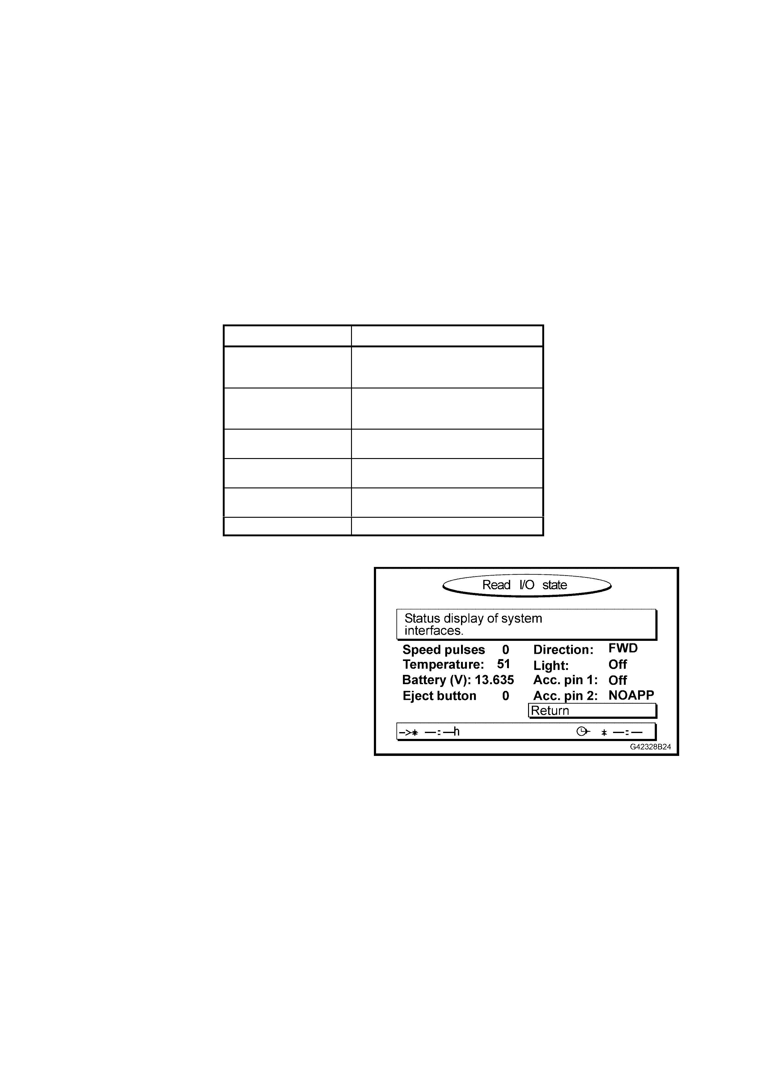
SUB-MENU NAME DESCRIPTION
READ I/O STATE Shows the values and state of
each input from the vehicle
electrical system.
SET I/O STATE Allows the computer to react to
positive or negative vehicle
signals.
READ GPS DATA Displays the current GPS receiver
condition.
READ ERROR Shows error event type and
frequency.
DEMO Enables and disables the
demonstration mode.
RETURN Returns to START MENU.
READ I/O STATE
This is the READ I/O screen. T he RETURN field is
automatically highlighted to return to the START
MENU when OK is pressed.
Figure 7B-38
FUNCTION DESCRIPTION NOMINAL VALUE COMMENT
Speed
Pulse Displays the number of
speedometer pulses per
second being read by the
computer.
Approx 100 at
60 km/h. If no pulses are shown whilst the vehicle is moving,
then confirm integrity of the VSS circuit. If circuit
OK, then replace the computer. The pulse value
should always be positive when the vehicle is
travelling forwards. Check the DIRECTION on the
same screen.
Temperature Displays the temperature
inside the navigation
computer.
45C at 20C outside
ambient
temperature.
System delivers specification to 70°C. Internal
computer fan turns on at 65°C and off at 60°C.
Battery (V) Displays the voltage level
present on the BATT
circuit.
13 – 15 V Low values (below 11 V) will cause deterioration in
picture quality. Low values (below 10 V) will cause
unstable operation.
Eject button Displays the condition of
the eject button located on
the computer front panel.
0 (released)
I (depressed)
Direction Displays the current state
of the reverse lamp circuit. FWD whilst in P, N,
or FORWARD
gears.
If value displayed is REV whilst in PARK, NEUTRAL
or FORWARD gear, then confirm the value set in
SET I/O STATE is ACT_HIGH. If the setting is
incorrect, then change the setting in SET I/O
STATE screen.
Light Displays the current state
of the park lamp circuit. ON (lights on)
OFF (lights off) If value displayed is ON when lights are off, then
confirm the value set in the SET I/O STATE is
ACT_HIGH. If the setting is incorrect, then change
the setting in the SET I/O STATE screen.
ACC. pin 1 Optional accessory input 1. OFF Not applicable.
ACC. pin 2 Optional accessory input 2. OFF Not applicable.
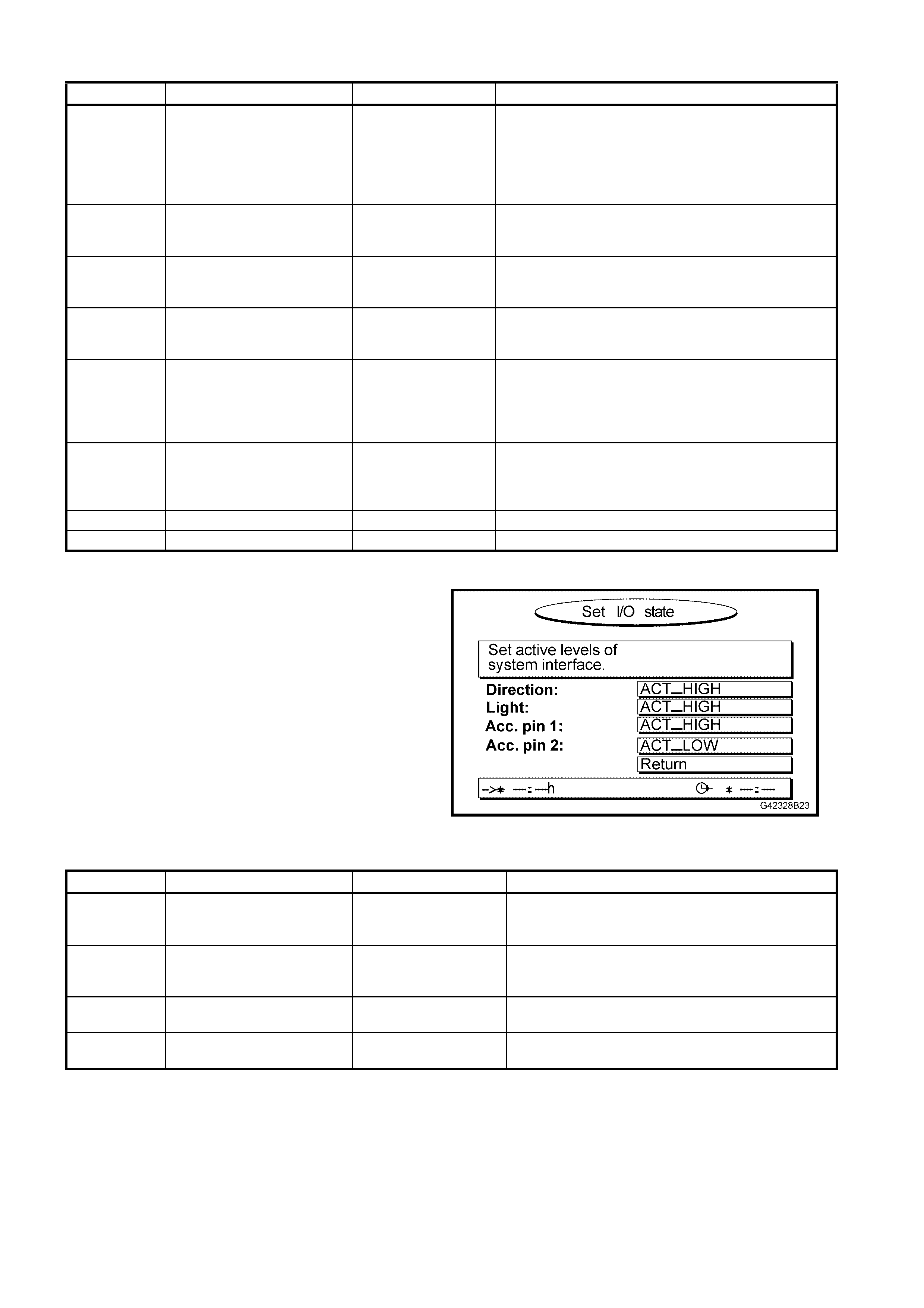
SET I/O STATE
This is the SET I/O STATE screen. The RETURN
field is automatically highlighted to return to the
START MENU when the OK button is pressed.
Figure 7B-39
FUNCTION DESCRIPTION NOMINAL VALUE COMMENT
Direction Sets the polarity of the
reverse lamp circuit for
computer processes.
ACT_HIGH For positive polarity reverse lamps, this is the
correct setting.
Light Sets the polarity of the
park lamp circuit for
computer processes.
ACT_HIGH For positive polarity park lamp, this is the correct
setting.
ACC. pin 1 Sets the polarity of optional
accessory input 1. ACT_HIGH These values may change when optional
navigation/multimedia accessories are connected.
ACC. pin 2 Sets the polarity of optional
accessory input 2. ACT_LOW These values may change when optional
navigation/multimedia accessories are connected.
READ GPS DATA
The common misconception made by service personnel when diagnosing navigation system performance
is to s us pect s atellite r ec eption as the c aus e of the f ault. In r eality, the GPS data sensed by the computer is
only processed every few seconds to confirm that the position calculated by the map matching software
process is c orr ec t. Good G PS data is es sential to the s ystem when it is f irs t ins talled in the vehic le, or when
the vehicle is moved from one location to another without the navigation system being active.
W ithin the SATNAV computer unit, there is a separate GPS receiver, which receives the GPS signal from
the antenna and passes calculated inf orm ation to the SAT NAV com puter ’s proc essor . If it is concluded that
the GPS receiver is faulty, the SATNAV computer must be replaced.
RECEIVER STATE DESCRIPTION COMMENT
3D POSITION 3D data on the location of
the vehicle is available when
four or more satellites are
received by the system.
In this condition, the satellite icon on the guidance screen is
GREEN. This is the normal condition.
2D POSITION 2D data on the location of
the vehicle is available when
three or more satellites are
received by the system.
No geographic height can be determined in this mode.
Positional accuracy is reduced.
The satellite icon on the guidance screen is RED. This is not
the normal condition, but indicates poor or reduced
reception.
TRACKING The data from one satellite
has been received by the
system.
This condition is normally encountered when the system is
first powered up. The GPS receiver will be in this mode for
up to 10 minutes depending upon reception conditions.
The satellite icon on the guidance screen is RED.
SEARCH SAT The system has a val id
almanac and is searching for
satellites.
This condition is normally encountered when the system is
first powered up. The GPS receiver will be in this mode for
up to 10 minutes depending upon reception conditions.
The satellite icon on the guidance screen is RED.
REC ERROR The system does not receive
the signals. This condition usually occurs if the GPS antenna is not
connected or the cable is damaged. A failed GPS receiver
could be the condition.
The satellite icon on the guidance screen is RED.
COM ERROR The GPS receiver is not
providing any data to the
SATNAV computer’s
processor.
Internal communication between the GPS receiver and the
SATNAV computer is not possible.
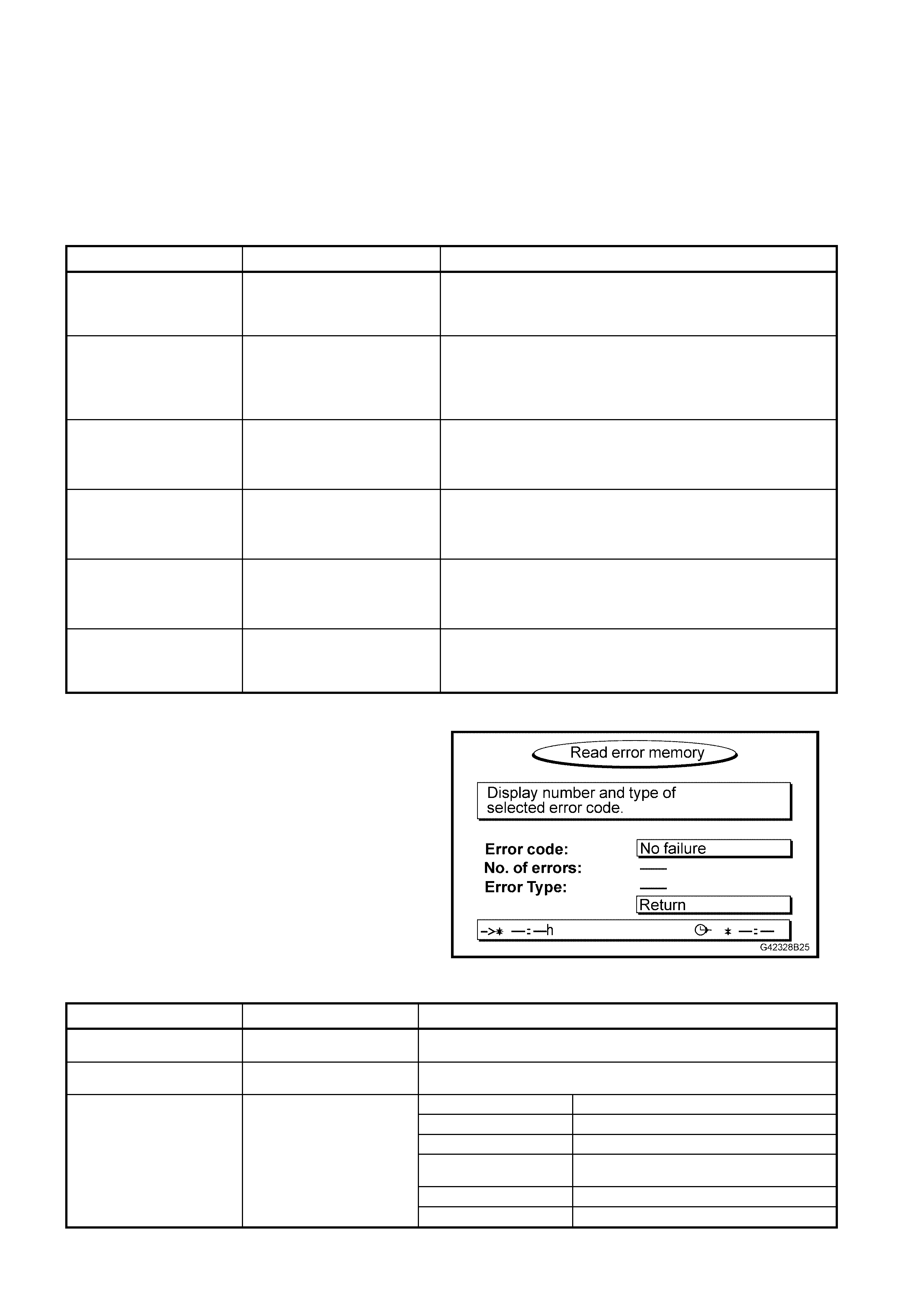
READ ERROR MEMORY
The self-diagnosis function of the computer stores
error events to its internal memory. The errors
detected may be due to internal (computer) or
external (environmental or vehicle) conditions. You
may need to view this screen when asked by a
VDO tec hnical consultant during the cour se of fault
diagnosis.
Figure 7B-40
MENU ITEM DESCRIPTION COMMENT
ERROR CODE Lists the errors that have
occurred. Scroll through the errors using the < and > buttons. Press OK
when each error is highlighted to see a description of the error.
ERROR FREQUENCY The number of times the
error has occurred.
SW Software error.
HW Hardware error.
SENSOR No VSS signal.
TEMP Temperature extreme has caused
system error.
GPS Lack of satellite signal.
ERROR TYPE Shows the error type.
NO FAILURE No errors have occurred.

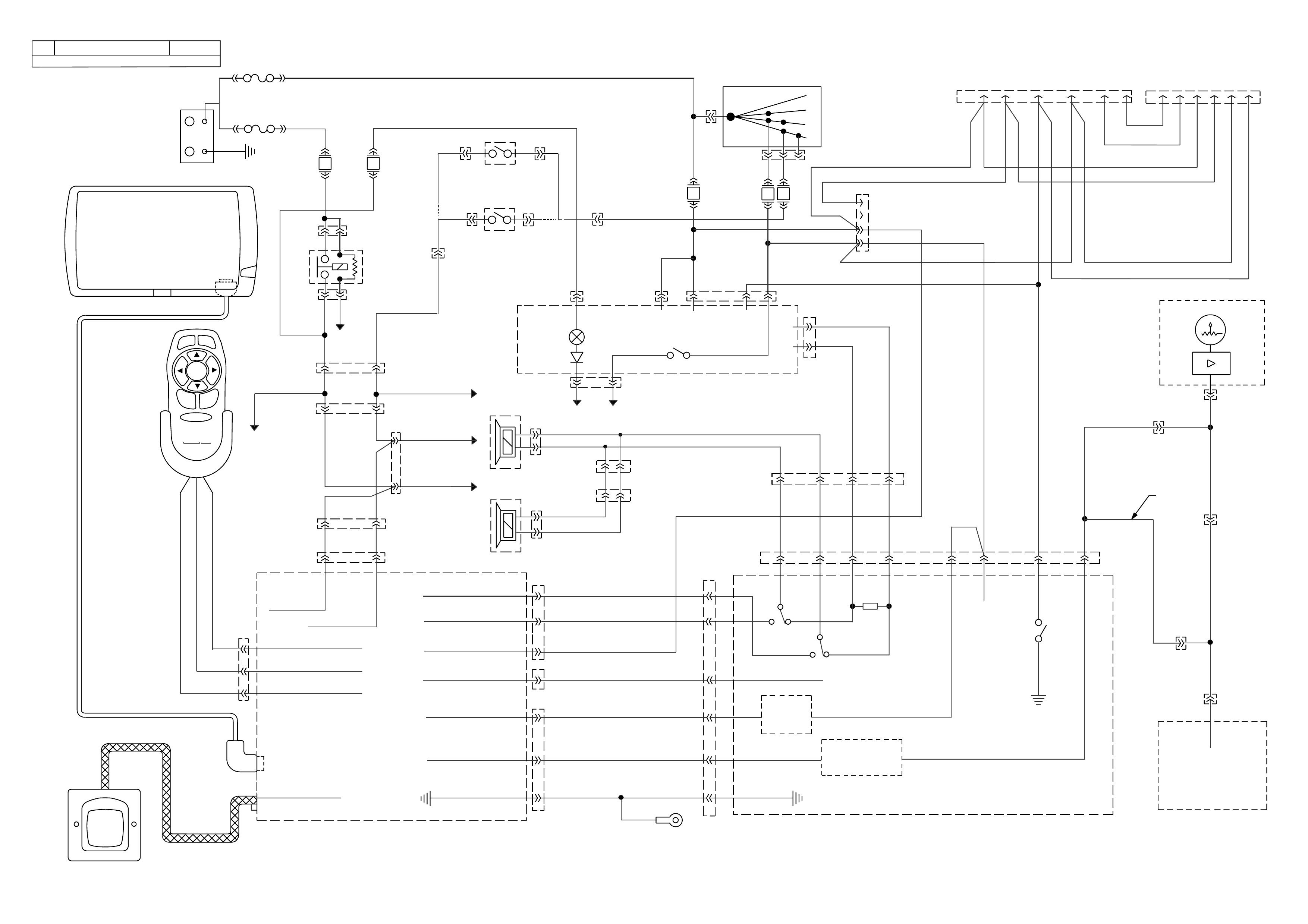
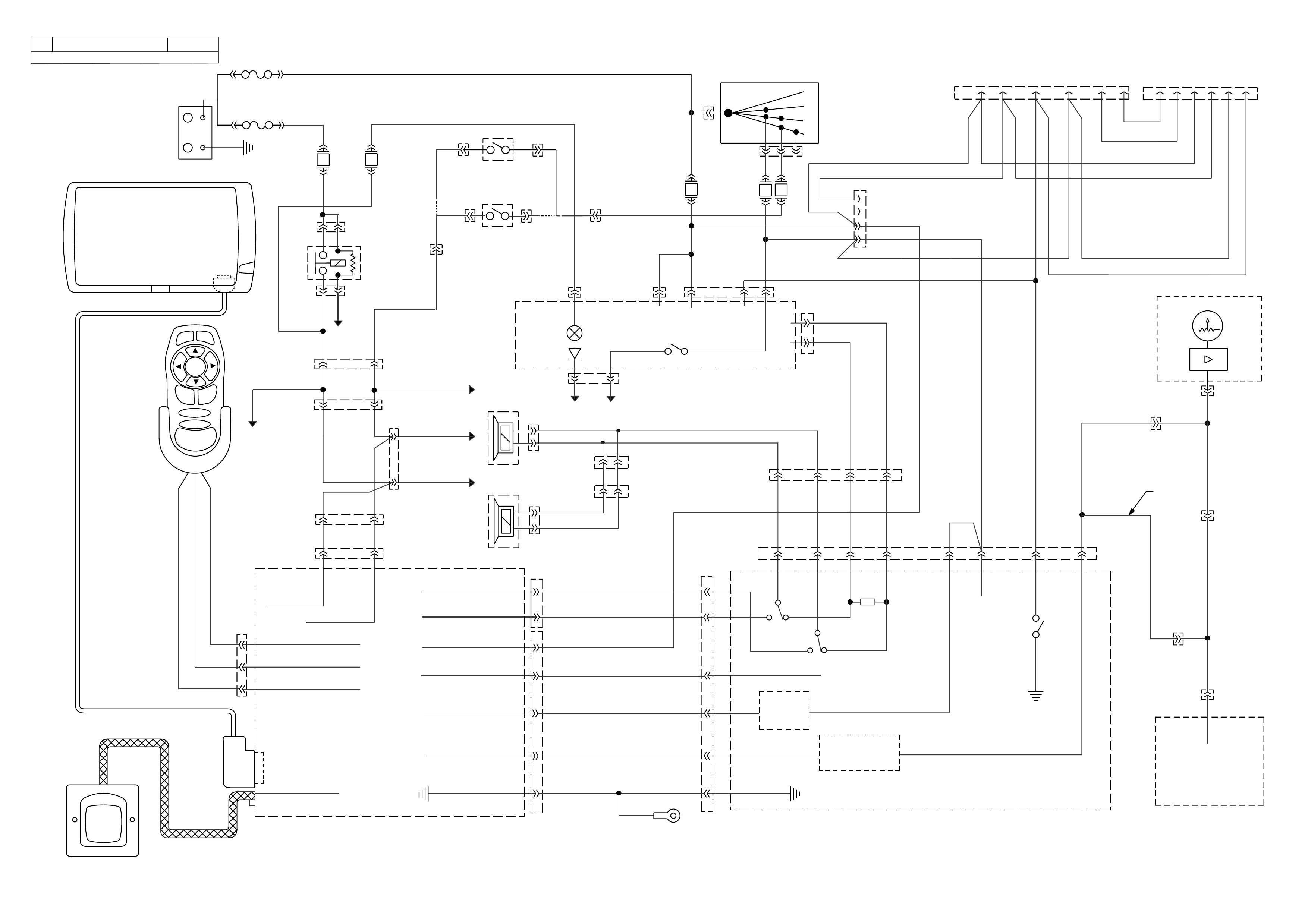
5. WH SATNAV WIRING DIAGRAMS
ALT - R
REP
ENTER
-
+
MENU
PHILIPSPHILIPS
carin
YR57
YR57
YR58
A2
A8
A1
B14
A3
A5
A7
A
A
B
YR58
B7 REMOTE SIGNAL : IN
-
POWERREMOTEB16
B8 REMOTE POWER +
Y
B
R
B
SATNAV MONITOR
CONNECTOR
FJ
(19)
(2H)
(2K)
(9)
BR/W
R
R
BR
BR
BLU
BATTERY
+
-
FQ
F4 F11
YB192
YB192
TO LIGHT
SWITCH
PARK
LAMPS
RELAY
YB39
TO LH PARK LAMPS
TO RH BACK-UP
LAMP
TO RH PARK
LAMP
TO LH BACK-UP LAMP
YB72 YB73
BATT BATT
RADIO
ILLUM
YB72
TO BCM
YB156
YB136
YB137
YB137
YR57
YR59
YR13 B
YR13 A
LF+
LF-
ACC
TELE
MUTE
YB72
YB72
YB44
F23 F16 F12
UP
BACK
SWITCH
YB40
YB40
BACK
UP
SWITCH
YB35 YB35
(MANUAL)
(AUTOMATIC)
YE112
Dk G
DKG
GPS
HARNESS
LG
BR BR BR
DKG
LIGHTS SENSE
REVERSE SENSE
A9 A4
GPS ANTENNA
YB44
IGNITION SWITCH
15a 15 50
30
OFF/ON
LOCK
ACC
IGN
START
BR
P
(4)
(3)
BR/BLU
YE 112
(42)
RADIO
T/B
GY/B
OB
(45)
Y/B (666)
SPEAKER OUT +
-
OUTSPEAKER
CONSTANT 12V
MUTE SIGNAL OUT
IGN + (10 SECOND DELAY)
VSS SIGNAL
SATNAV COMPUTER
100R
6
-
LF
RADIO
LF+
RADIO
14
LF+
SPEAK.
-
LF
SPEAK.
13
BLU/G
BLU
O/B
W
Y/W
B/W
BB
SATNAV
GND
8GND
4
12
9 MUTE FROM GPS
SPEED SIGNAL
BUFFER
10 SECOND
TIMER
11
7VSS OUT
GPS INTERFACE
3
1
4
2
YB23
O/B
Y
O/B
Y
(45)
(43)
BG
BG
O/B (45)
(151)
Y
Y
(43)
(43)
2143
O/B
(45)
YB11
YB74
YB77
124356 651234
PHONE (BLACK) WH CAPRICE
PHONE (WHITE) WH
BLU
B/BLU
OB
BG
(45)
(151)
510 ACC ACC
12V 12V
23MUTE
OUT
VSS
IN
1
SPEEDO
INSTRUMENTS
Y
Y/B
(43)
(666)
C5 V6
C1 V6 S/C
J2-50 GEN III V8
POWER TRAIN
CONTROL MODULE
V6, V6 S/C &
GEN III V8
YB193 V6
YB138
YB138
YB66
YB188 V6 S/C
YE123 GEN III V8
V
V6 &
V6 S/C
V
V/W
GEN III V8 V/WV
YE110
V/W
(123)
V/W
LG
T
GY
GY
T
GY/B
T/B
Y
Y
Y/B
(43)
Y/B
Y/B
Y
Y
17
R
B
Y
A
GPS ANTENNA
VDO
SATNAV MONITOR
SATNAV
REMOTE
CONTROL
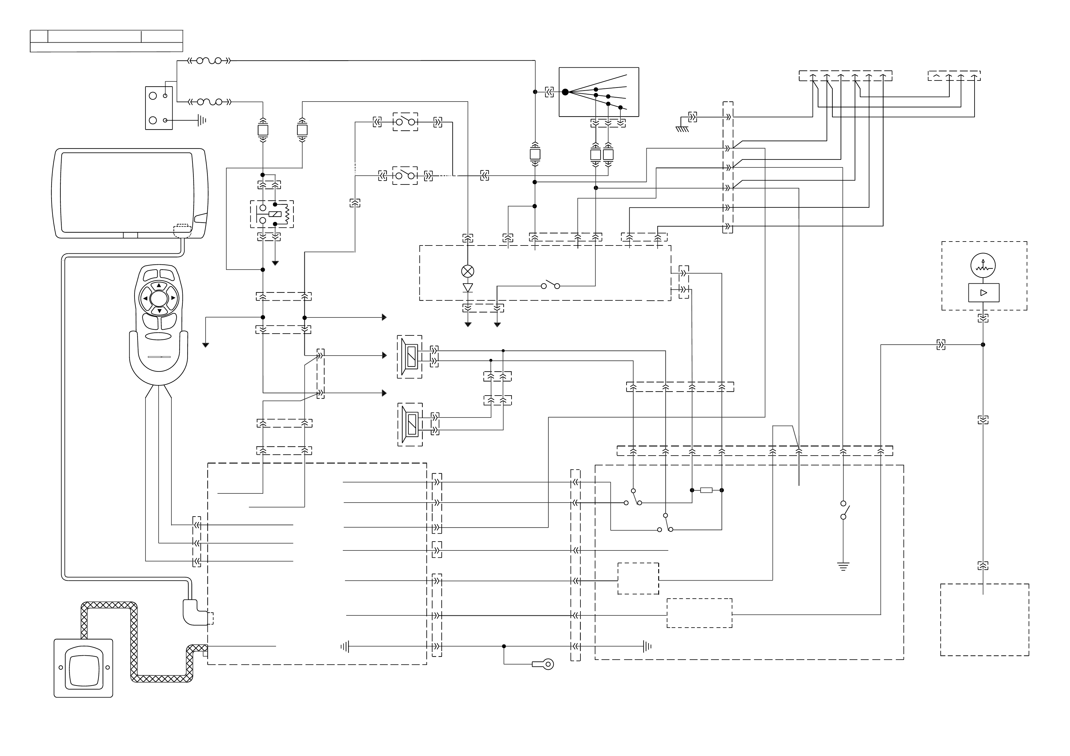
STATESMAN
MODEL WH1A
SATNAV ( )PHILIPS CARIN
LHF DASH
SPEAKER
LHF DOOR
SPEAKER
+
-
-
+
G4237B15
FJ
(19)
(2H)
(2K)
(9)
BR/W
R
R
BR
BR
BLU
BATTERY
+
-
FQ
F4 F11
YB192
YB192
TO LIGHT
SWITCH
PARK
LAMPS
RELAY
YB39
TO LH PARK LAMPS
TO RH BACK-UP
LAMP
TO RH PARK
LAMP
TO LH BACK-UP LAMP
YB72 YB73
BATT BATT
RADIO
ILLUM
YB72
TO BCM
YB156
YB136
YB137
YB137
YR58
YR58
YR57
YR59
YR13 B
YR13 A
YR57
LF+
LF-
ACC
TELE
MUTE
YB72
YB72
YB44
F23 F16 F12
UP
BACK
SWITCH
YB40
YB40
BACK
UP
SWITCH
YB35 YB35
(MANUAL)
(AUTOMATIC)
YE112
Dk G
DKG
GPS
HARNESS
LG
BR BR BR
DKG
LIGHTS SENSE
REVERSE SENSE
A6 A2
B1 REMOTE SIGNAL : IN
-
POWERREMOTEB2
B3 REMOTE POWER +
Y
B
R
GPS ANTENNA
YB44
IGNITION SWITCH
15a 15 50
30
OFF/ON
LOCK
ACC
IGN
START
BR
P
(4)
(3)
BR/BLU
YE 112
(42)
RADIO
T/B
GY/B
OB (45)
Y/B (666)
SPEAKER OUT + B5
-
OUTSPEAKER B6
CONSTANT 12V A4
MUTE SIGNAL OUT A3
IGN + (10 SECOND DELAY) A7
VSS SIGNAL A1
A8
SATNAV MONITOR
16 PIN CONNECTOR
SATNAV COMPUTER
100R
6
-
LF
RADIO
LF+
RADIO
14
LF+
SPEAK.
-
LF
SPEAK.
13
BLU/G
BLU
O/B
W
Y/W
B/W
BB
SATNAV
GND
8GND
4
12
9 MUTE FROM GPS
SPEED SIGNAL
BUFFER
10 SECOND
TIMER
11
7VSS OUT
GPS INTERFACE
3
1
4
2
YB23
O/B
Y
O/B
Y
(45)
(43)
BG
BG
O/B (45)
(151)
Y
Y
(43)
(43)
2143
O/B (45)
YB11
YB74
YB77
124356 651234
PHONE (BLACK) WH CAPRICE
PHONE (WHITE) WH
BLU
B/BLU
OB
BG
(45)
(151)
510 ACC ACC
12V 12V
23MUTE
OUT
VSS
IN
1
SPEEDO
INSTRUMENTS
Y
Y/B
(43)
(666)
C5 V6
C1 V6 S/C
J2-50 GEN III V8
POWER TRAIN
CONTROL MODULE
V6,V6S/C&
GEN III V8
YB193 V6
YB138
YB138
YB66
YB188 V6 S/C
YE123 GEN III V8
V
V6 &
V6 S/C
V
V/W
GEN III V8 V/WV
YE110
V/W (123)
V/W
A
B
LG
T
GY
GY
T
GY/B
T/B
Y
Y
Y/B
(43)
Y/B
Y/B
Y
Y
17
R
B
Y
A
B
GPS ANTENNA
VDO
ALT - R
REP
OK
-
+
MENU
MAP
HSV
SATNAV MONITOR
SATNAV
REMOTE
CONTROL
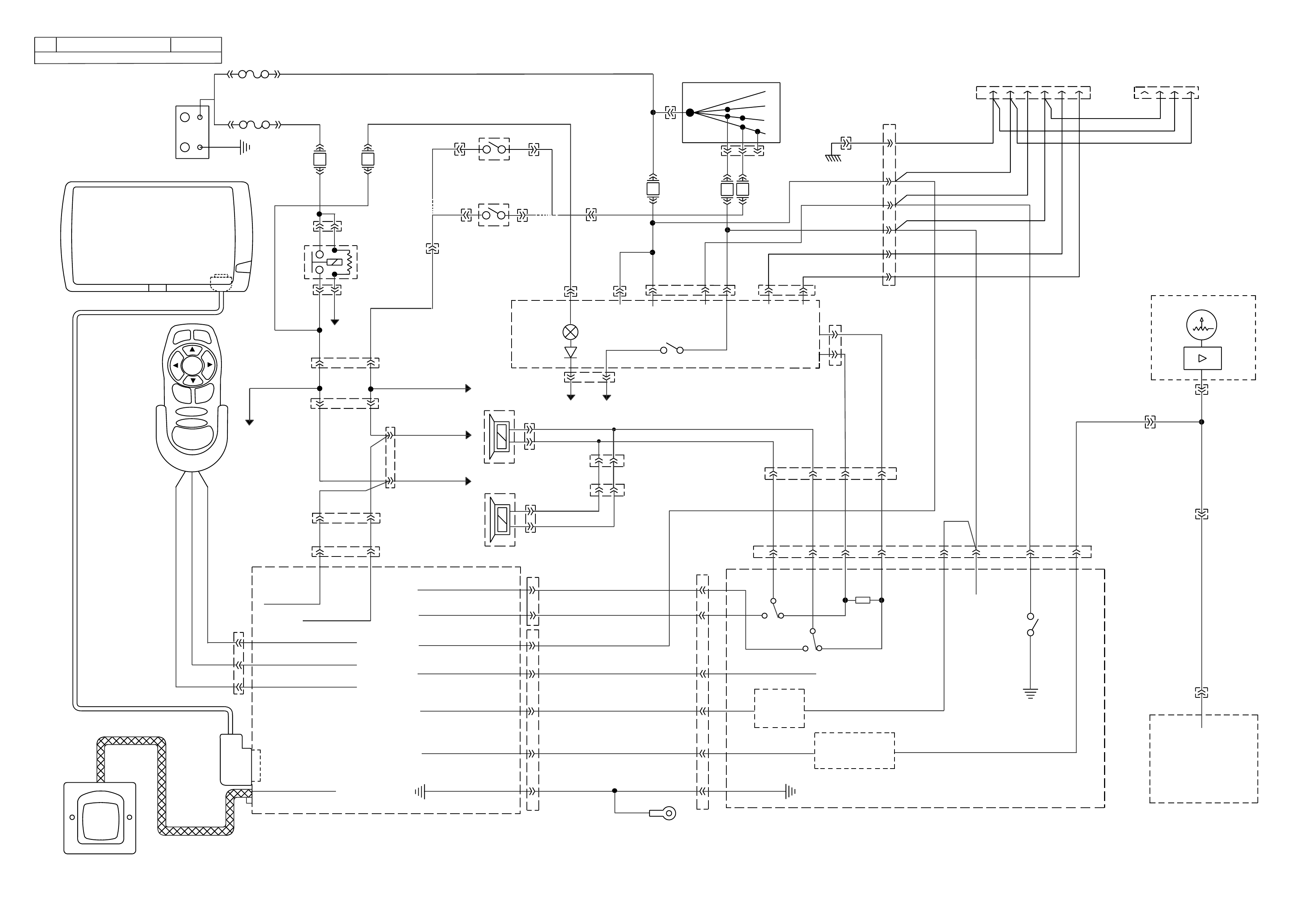
STATESMAN
MODEL WH1A
SATNAV ( )MS5000
LHF DASH
SPEAKER
LHF DOOR
SPEAKER
+
-
-
+
G4237B13
G4237B13A
DOOR SPEAKER CONNECTOR
YB11 (DOOR HARNESS)
BR/B
RHR
(46)
Y/BLU
BLU/O
(116)
BLU/B
LHR
(199)
(115)
G
(118)
LHF
RHF
(201)
(200)
T
LG
(117)
GY
NEUTRAL START & BACK-UP SWITCH
YB35 (POWER TRAIN HARNESS)
(1434)
GY/BLU
(24)
LG GY(434)
(750)
B/R
(42)
BR/BLU
YB40 (POWER TRAIN HARNESS)
MANUAL TRANS BACK UP SWITCH
LG (24)
(42)
BR/BLU
BODY HARNESS CONNECTOR
YB39 (M.W.H)
(151)
(782)
(783)
(1220)
(116)
(199)
(540)
Y/BLU
BR/B
O/B
LG
BLU/O
BLU/B V/R
O/Y
V
G
BR
BLU/R
BLU
LBLU
LG
G
(15)
(24)
(46)
(115)
(1240) (322)
(120)
(192)
(9)
(20)
(14)
(117)
(641)
(200)
(43)
(701)
(315)
G/W
B/G
W
B/Y
Y
O/W
V
Y/B
IGNITION SWITCH
YB44 (M.W.H)
BR(4)
V(5)
(2)
R
(3)
P
YB66 (M.W.H)
INSTRUMENTS
T
BLU/B
BR/W
(234)
(25)
(14)
(10)
(875)
(155)
(1340)
G/W
(44)
(121)
(8)
(30)
BLU/Y
G
O/Y
P/BLU
BR/R
V/W
(33)
(946)
(1220)
(88)
(15)
(123)
(85)
(19)
GY
W
V/R
BR
BR/O
Y/R
B/Y
LBLU
BLU
YB72 (M.W.H)
RADIO
(115)
(46)
(117) (200)
LG
G
BLU/O
BLU/B
Y/BLU
BR/B
GY
(116)
(199)
(118)
(201)
T
(143)
(19)
BR/W
Y/R
B/W
Y
(1151)
(43)
Y/B(656)
GY W
LBLU
(8) (160)
(161)
(45)
O/B
YB74 (M.W.H)
BODY HARNESS CONNECTOR
(317)
(299)
(246)
(321)
R/Y
BR/O
BLU/R
Y
GY
O/B
W/G
T
G
T
P
LBLU
B/Y
(30)
(174)
(1145)
(118)
(342)
(201)
(139)
(411)
(155)
(47)
(882)
(883)
(884)
(885)
(33)
O/BLU
B
BLU
V
Y
BR/O
B/G(255)
(155)
B/Y
YB137 (SATNAV HARNESS)
V
1
6
7
14
YY/B BLU TT/B
GY/B
GY
BLU/G
B/W
BWYY/W
GPS INTERFACE CONNECTOR
YB156 (M.W.H)
DASHBOARD SPEAKER CONNECTOR
(200)
LG
(201)
T
(117)
G
(118)
GY
R.H
L.H
YB192 (M.W.H)
PARK LAMPS RELAY
(49)
BLU
(840)
O/W BR(9)
O/W(840)
YB188 (POWER TRAIN HARNESS)
(481)
(417)
(740)
R
BLU
O/B
(1456)
LG
V/W(415) Y
(1227)
B/Y (410) BR(472)
(259)
(750)
(750)
(1221)
B/R
B/R
R/B
G/B
(39)
P
(465)
G/W
(416)
GY
(740)
O/B
A1
B1
B12
A12
P.C.M. CONNECTOR 2 (S/C ONLY)
YB193 (POWER TRAIN HARNESS)
(413)
(412)
(1413)
(1412)
(430)
(453)
(815)
V/B
GY/B
V
GY
V
B/R
W/R
(897)
(897)
G/W
G/W
(418)
(418)
BR
BR
(1426)
O/W
C16
D16
WT/B
(832)
(647)
(630)
T
LBLU/B
B
(424)
(423)
C1
D1
(792)
(422)
(1222)
(1223)
(428)
(123)
BR/W
GY/R
LG
Y/B
G/Y
V/W
BLU/W
(443)
LG/W
(442) (831)
(441)
LBLU
LBLU/B
(444)
LG/B
P.C.M. CONNECTOR 1
ENGINE CONNECTOR 3
YE112 (M.W.H)
V6 S/C ONLY
(1221)
(42)
(121)
BR/BLU
BR/R
R/B
O/B
LG
P/B
BLU
(740)
(24)
(39)
(774)
LBLU(411)
ENGINE CONNECTOR 1
YE110 (M.W.H)
(304)
BLU/W
G/W
(339)
P/BLU
(465)
(123)
V/W
(1427)
B/W
Y(1049)
O/W(1426)
YE123 (POWER TRAIN HARNESS)
P.C.M CONNECTOR 2
(750)
(1228)
(1229)
(465)
(121)
(259)
G/B
BR
G/W
GY/BLU
R
B/R
(418)
BR
(59)
(832)
G
T
(831)
(417)
(472)
(976) (974)
(432)
(428)
(631)
BLU
BR G/Y
BLU/W
LG
BR/W
W/B
LG W
(977)
Y
(971)
BLU/W
W
B/R (750)
(304)
(792)
(1223)
(1222)
(123)
(1227)
(469)
(331)
Y/B
LG
V/W
B/Y
G/O
BR/W
(1687)
GY/B
(366)
LG/B
GY/R (422)
V
(442)
(444)
(443)
(975)
(972)
(978)
(1224)
(973)
(959) LG/W
LG/B
LBLU/B
GY(773)
BR/Y
BLU
G
Y/B
LBLU
(958)
BR
(441)
LBLU
1
41
40
80
J2
RED
Y(838)
BLU/R BLU/R
(15) (15)(R.H) (R.H)
(R.H) (R.H)
YR13"A" (SATNAV LIGHT PATCH HARNESS)
YR13 "B" (BODY HARNESS)
BR BR
(156) (156)
BLU BLU
TAIL LAMPS CONNECTOR TAIL LAMPS CONNECTOR
(20) (20)
LG LG
N/C N/C
(24) (24)
B/BLU B/BLU
(14) (14)(L.H) (L.H)
(L.H) (L.H)
LBLU LBLU
(9) (9)
BR/W BR/W
(1251) (1251)
CELLULAR TELEPHONE CONNECTOR
YB23 (M.W.H)
O/B
B/G
(43)
(656) (45)
(151)
Y
Y/B
YB73 (M.W.H)
RADIO CONNECTOR
(515)
(701)
(1151)
BR
B/Y
B/W
O/B
V
(45)
(782)
YB77 (BODY HARNESS)
L.H. FRONT DOOR HARNESS CONNECTOR
9
6
8
3
3
579
246
4
17
2
8
1
5
(1145)
(294)
(194)
(908)
(909) (911)
(1124)
(667)
O/B
B/R
BR/O
G
GY
VBR W/BLU
(195)
BR/R
B/Y
(394)
(666)
(156)
BLU
B/BLU
V/W
(295)
(118)
(201)
T
GY
YB136 (SATNAV HARNESS)
RADIO PATCH HARNESS CONNECTOR
GY/B
T/B
GY
P
YB138 (SATNAV HARNESS)
V
SATNAV SPEED SENSOR CONNECTOR
YR59 (SATNAV HARNESS)
BR G
SATNAV LAMP PATCH CONNECTOR
YR57 (SATNAV HARNESS)
SATNAV COMPUTER CONNECTOR (A)
WO/B
DKG
B/W
BR Y/W B
1
4
8
5
(VDO DAYTON MS5000)
YR58 (SATNAV HARNESS)
Y
1
54
8
BR
BLU BLU/G
SATNAV REMOTE CONTROL CONNECTOR (B)
(VDO DAYTON MS5000)
YR57 (SATNAV HARNESS)
SATNAV COMPUTER CONNECTOR (A)
(PHILIPS CARIN)
B/W
DKG
Y/W
BLU
O/B
B
BLU/G BR
6
7
12
1
YR58 (SATNAV HARNESS)
SATNAV REMOTE CONTROL CONNECTOR (B)
(PHILIPS CARIN)
8
1
16
9
B
R
Y
W
FJ
(19)
(2H)
(2K)
(9)
BR/W
R
R
BR
BR
BLU
BATTERY
+
-
FQ
F4 F11
YB192
YB192
PARK
LAMPS
RELAY
YB72 YB73
BATT BATT
YB72
YB136
YB137
YB137
ACC
TELE
MUTE
YB72
YB72
YB44
F23 F16 F12
UP
BACK
SWITCH
YB40
YB40
BACK
UP
SWITCH
YB35 YB35
(MANUAL)
(AUTOMATIC)
YE112
YB44
IGNITION SWITCH
15a 15 50
30
OFF/ON
LOCK
ACC
IGN
START
BR
P
(4)
(3)
BR/BLU
YE 112
(42)
RADIO
T
OB (45)
LF+
LF-
100R
6
-
LF
RADIO
LF+
RADIO
14
LF+
SPEAK.
-
LF
SPEAK.
13
BLU/G
BLU
O/B
W
Y/W
B/W
B
SATNAV
GND
8GND
4
12
9 MUTE FROM GPS
SPEED SIGNAL
BUFFER
10 SECOND
TIMER
11
7VSS OUT
GPS INTERFACE
2143
O/B
G/B (118)
2
1
4356
PHONE (WHITE) WH STATESMAN
510 ACC ACC
12V 12V
23MUTE
OUT
VSS
IN
1
SPEEDO
INSTRUMENTS
J2-50 GEN III V8
POWER TRAIN
CONTROL MODULE
GEN III V8
YB138
YB66
1
2
4
3
5
6
YE123 GEN III V8
V
V/W
GEN III V8 V/WV
YE110
V/W (123)
V/W
LG
T
GY
GY
T
GY/B
T/B
Y
Y
Y/B
17
VDO
SATNAV MONITOR
CAPRICE
MODEL WH1A
SATNAV ( )PHILIPS CARIN
YE11 4
PHONE
SIGNAL
GND
PHONE
SIGNAL
YB73
3
14
2
O/B
O/B
Y/B
Y
BLU
BLU/B
B/G
(45)
(656)
(43)
(659)
(201)
(665)
Y
G4237B16
TO LIGHT
SWITCH
YB39
TO LH PARK LAMPS
TO RH BACK-UP
LAMP
TO RH PARK
LAMP
TO LH BACK-UP LAMP
RADIO
ILLUM
TO BCM
YB156
YR57
YR58
YR57
YR59
YR13 B
YR13 A
YR57
YR58
Dk G
DKG
GPS
HARNESS
LG
BR BR BR
DKG
LIGHTS SENSE
REVERSE SENSE
A9 A4
B7 REMOTE SIGNAL : IN
-
POWERREMOTEB16
B8 REMOTE POWER +
Y
B
R
GPS ANTENNA
SPEAKER OUT + A2
-
OUTSPEAKER A8
CONSTANT 12V A1
MUTE SIGNAL OUT B14
IGN + (10 SECOND DELAY) A3
VSS SIGNAL A5
A7
SATNAV MONITOR
CONNECTOR
SATNAV COMPUTER
B
YB11
YB74
YB77
A
A
B
R
B
Y
A
B
GPS ANTENNA
ALT - R
REP
ENTER
-
+
MENU
PHILIPSPHILIPS
carin
SATNAV
REMOTE
CONTROL LHF DASH
SPEAKER
LHF DOOR
SPEAKER
+
-
-
+
FJ
(19)
(2H)
(2K)
(9)
BR/W
R
R
BR
BR
BLU
BATTERY
+
-
FQ
F4 F11
YB192
YB192
TO LIGHT
SWITCH
PARK
LAMPS
RELAY
YB39
TO LH PARK LAMPS
TO RH BACK-UP
LAMP
TO RH PARK
LAMP
TO LH BACK-UP LAMP
YB72 YB73
BATT BATT
RADIO
ILLUM
YB72
TO BCM
YB156
YB136
YB137
YB137
YR58
YR58
YR57
YR59
YR13 B
YR13 A
YR57
ACC
TELE
MUTE
YB72
YB72
YB44
F23 F16 F12
UP
BACK
SWITCH
YB40
YB40
BACK
UP
SWITCH
YB35 YB35
(MANUAL)
(AUTOMATIC)
YE112
Dk G
DKG
GPS
HARNESS
LG
BR BR BR
DKG
LIGHTS SENSE
REVERSE SENSE
A6 A2
B1 REMOTE SIGNAL : IN
-
POWERREMOTEB2
B3 REMOTE POWER +
Y
B
R
GPS ANTENNA
YB44
IGNITION SWITCH
15a 15 50
30
OFF/ON
LOCK
ACC
IGN
START
BR
P
(4)
(3)
BR/BLU
YE 112
(42)
RADIO
T
OB (45)
SPEAKER OUT + B5
-
OUTSPEAKER B6
CONSTANT 12V A4
MUTE SIGNAL OUT A3
IGN + (10 SECOND DELAY) A7
VSS SIGNAL A1
A8
SATNAV MONITOR
16 PIN CONNECTOR
SATNAV COMPUTER
LF+
LF-
100R
6
-
LF
RADIO
LF+
RADIO
14
LF+
SPEAK.
-
LF
SPEAK.
13
BLU/G
BLU
O/B
W
Y/W
B/W
BB
SATNAV
GND
8GND
4
12
9 MUTE FROM GPS
SPEED SIGNAL
BUFFER
10 SECOND
TIMER
11
7VSS OUT
GPS INTERFACE
2143
O/B
G/B (118)
YB11
YB74
YB77
2
1
4356
PHONE (WHITE) WH STATESMAN
510 ACC ACC
12V 12V
23MUTE
OUT
VSS
IN
1
SPEEDO
INSTRUMENTS
J2-50 GEN III V8
POWER TRAIN
CONTROL MODULE
GEN III V8
YB138
YB66
1
2
4
3
5
6
YE123 GEN III V8
V
V/W
GEN III V8 V/WV
YE110
V/W (123)
V/W
A
B
LG
T
GY
GY
T
GY/B
T/B
Y
Y
Y/B
17
R
B
Y
A
B
GPS ANTENNA
VDO
ALT - R
REP
OK
-
+
MENU
MAP
HSV
SATNAV MONITOR
SATNAV
REMOTE
CONTROL
CAPRICE
MODEL WH1A
SATNAV ( )MS5000
LHF DASH
SPEAKER
LHF DOOR
SPEAKER
+
-
-
+
YE11 4
PHONE
SIGNAL
GND
PHONE
SIGNAL
YB73
3
14
2
O/B
O/B
Y/B
Y
BLU
BLU/B
B/G
(45)
(656)
(43)
(659)
(201)
(665)
Y
G4237B14
G4237B14A
DOOR SPEAKER CONNECTOR
YB11 (DOOR HARNESS)
BR/B
RHR
(46)
Y/BLU
BLU/O
(116)
BLU/B
LHR
(199)
(115)
G
(118)
LHF
RHF
(201)
(200)
T
LG
(117)
GY
NEUTRAL START & BACK-UP SWITCH
YB35 (POWER TRAIN HARNESS)
(1434)
GY/BLU
(24)
LG GY(434)
(750)
B/R
(42)
BR/BLU
YB40 (POWER TRAIN HARNESS)
MANUAL TRANS BACK UP SWITCH
LG (24)
(42)
BR/BLU
BODY HARNESS CONNECTOR
YB39 (M.W.H)
(151)
(782)
(783)
(1220)
(116)
(199)
(540)
Y/BLU
BR/B
O/B
LG
BLU/O
BLU/B V/R
O/Y
V
G
BR
BLU/R
BLU
LBLU
LG
G
(15)
(24)
(46)
(115)
(1240) (322)
(120)
(192)
(9)
(20)
(14)
(117)
(641)
(200)
(43)
(701)
(315)
G/W
B/G
W
B/Y
Y
O/W
V
Y/B
IGNITION SWITCH
YB44 (M.W.H)
BR(4)
V(5)
(2)
R
(3)
P
YB66 (M.W.H)
INSTRUMENTS
T
BLU/B
BR/W
(234)
(25)
(14)
(10)
(875)
(155)
(1340)
G/W
(44)
(121)
(8)
(30)
BLU/Y
G
O/Y
P/BLU
BR/R
V/W
(33)
(946)
(1220)
(88)
(15)
(123)
(85)
(19)
GY
W
V/R
BR
BR/O
Y/R
B/Y
LBLU
BLU
YB72 (M.W.H)
RADIO
(115)
(46)
(117) (200)
LG
G
BLU/O
BLU/B
Y/BLU
BR/B
GY
(116)
(199)
(118)
(201)
T
(143)
(19)
BR/W
Y/R
B/W
Y
(1151)
(43)
Y/B(656)
GY W
LBLU
(8) (160)
(161)
(45)
O/B
YB74 (M.W.H)
BODY HARNESS CONNECTOR
(317)
(299)
(246)
(321)
R/Y
BR/O
BLU/R
Y
GY
O/B
W/G
T
G
T
P
LBLU
B/Y
(30)
(174)
(1145)
(118)
(342)
(201)
(139)
(411)
(155)
(47)
(882)
(883)
(884)
(885)
(33)
O/BLU
B
BLU
V
Y
BR/O
B/G(255)
(155)
B/Y
YB156 (M.W.H)
DASHBOARD SPEAKER CONNECTOR
(200)
LG
(201)
T
(117)
G
(118)
GY
R.H
L.H
YB192 (M.W.H)
PARK LAMPS RELAY
(49)
BLU
(840)
O/W BR(9)
O/W(840)
ENGINE CONNECTOR 3
YE112 (M.W.H)
(1221)
(42)
(121)
BR/BLU
BR/R
R/B
O/B
LG
P/B
BLU
(740)
(24)
(39)
(774)
ENGINE CONNECTOR 1
YE110 (M.W.H)
(304)
BLU/W
G/W
(339)
P/BLU
(465)
(123)
V/W
(1427)
B/W
Y(1049)
O/W(1426)
YE123 (POWER TRAIN HARNESS)
P.C.M CONNECTOR 2
(750)
(1228)
(1229)
(465)
(121)
(259)
G/B
BR
G/W
GY/BLU
R
B/R
(418)
BR
(59)
(832)
G
T
(831)
(417)
(472)
(976) (974)
(432)
(428)
(631)
BLU
BR G/Y
BLU/W
LG
BR/W
W/B
LG W
(977)
Y
(971)
BLU/W
W
B/R (750)
(304)
(792)
(1223)
(1222)
(123)
(1227)
(469)
(331)
Y/B
LG
V/W
B/Y
G/O
BR/W
(1687)
GY/B
(366)
LG/B
GY/R (422)
V
(442)
(444)
(443)
(975)
(972)
(978)
(1224)
(973)
(959) LG/W
LG/B
LBLU/B
GY(773)
BR/Y
BLU
G
Y/B
LBLU
(958)
BR
(441)
LBLU
1
41
40
80
J2
RED
Y(838)
YB77 (BODY HARNESS)
L.H. FRONT DOOR HARNESS CONNECTOR
9
6
8
3
3
579
246
4
17
2
8
1
5
(1145)
(294)
(194)
(908)
(909) (911) (1124)
(667)
O/B
B/R
BR/O
G
GY
VBR W/BLU
(195)
BR/R
B/Y
(394)
(666)
(156)
BLU
B/BLU
V/W
(295)
(118)
(201)
T
GY
CELLULAR TELEPHONE CONNECTOR
YB23 (M.W.H)
O/B
(45)
B/G
(151)
Y
(43)
Y/B
(656)
BLU/B
(665)
BLU
(659)
YB73 (M.W.H)
RADIO CONNECTOR
(665)
(299)
(246)
(659)
(317) (782) (701)
(45)
(315)
(515)
BLU/R
BR/O
BLU/B
BLU
R/Y
BR
W
O/B
B/Y
V
O/B
(45)
B/G
(255)
YB136 (SATNAV HARNESS)
RADIO PATCH HARNESS CONNECTOR
GY/B
T/B
GY
P
YB138 (SATNAV HARNESS)
V
SATNAV SPEED SENSOR CONNECTOR
YB137 (SATNAV HARNESS)
V
1
6
7
14
YY/B BLU TT/B
GY/B
GY
BLU/G
B/W
BWYY/W
GPS INTERFACE CONNECTOR
BLU/R BLU/R
(15) (15)(R.H) (R.H)
(R.H) (R.H)
YR13 "A" (SATNAV LIGHT PATCH HARNESS)
YR13 "B" (BODY HARNESS)
BR BR
(156) (156)
BLU BLU
TAIL LAMPS CONNECTOR TAIL LAMPS CONNECTOR
(20) (20)
LG LG
N/C N/C
(24) (24)
B/BLU B/BLU
(14) (14)(L.H) (L.H)
(L.H) (L.H)
LBLU LBLU
(9) (9)
BR/W BR/W
(1251) (1251)
YR59 (SATNAV HARNESS)
BR G
SATNAV LAMP PATCH CONNECTOR
YR57 (SATNAV HARNESS)
SATNAV COMPUTER CONNECTOR (A)
WO/B
DKG
B/W
BR Y/W B
1
4
8
5
(VDO DAYTON MS5000)
YR58 (SATNAV HARNESS)
Y
1
54
8
BR
BLU BLU/G
SATNAV REMOTE CONTROL CONNECTOR (B)
(VDO DAYTON MS5000)
YR57 (SATNAV HARNESS)
SATNAV COMPUTER CONNECTOR (A)
(PHILIPS CARIN)
B/W
DKG
Y/W
BLU
O/B
B
BLU/G BR
6
7
12
1
YR58 (SATNAV HARNESS)
SATNAV REMOTE CONTROL CONNECTOR (B)
(PHILIPS CARIN)
8
1
16
9
B
R
Y
W
LOCATION E3 EARTH CONNECTOR
YE114 (M.W.H)
(151)
B/G
(157)
B/R
(150) (155)
BB/Y
(152)
B/W
(157)
B/R