
SECTION 10B - V2 SERIES HBD OPTIONS
1.0 GENERAL INFORM ATION
This Section of the Holden By Design Service Manual Supplement describes the following option packages
available for V2 Series vehicles:
• Decklid spoiler,
• 17” x 8” X-series 8 spoke alloy wheels fitted with 235/45 V-rated tyres,
• 17” x 8” Statesman International 6 spoke alloy wheels fitted with 235/45 V-rated tyres,
• 17” x 8” Calais International alloy wheels fitted with 235/45 V-rated tyres.
When the decklid spoiler is fitted, a Holden By Design identification plate and decals are included as part of the
package. The decklid gas struts are also upgraded to compensate the weight of the spoiler. When ordering
replacement units, the correct struts for a decklid fitted with a Holden By Design spoiler must be specified.
Also available, but not described in this Supplement is the HBD Hand Control System. Service information for the
hand control system can be found in Section 4J VT & WH HAND CONTROL SYSTEM.
2.0 DECKLID SPOILER
NOTE: The spoiler is painted in the vehicle’s body colour. The painting procedures are relatively straight forward
providing the correct steps are followed for PUR (polyurethane with rigid structure foam core m aterial). If required,
refer to your paint manufacturer for further information.
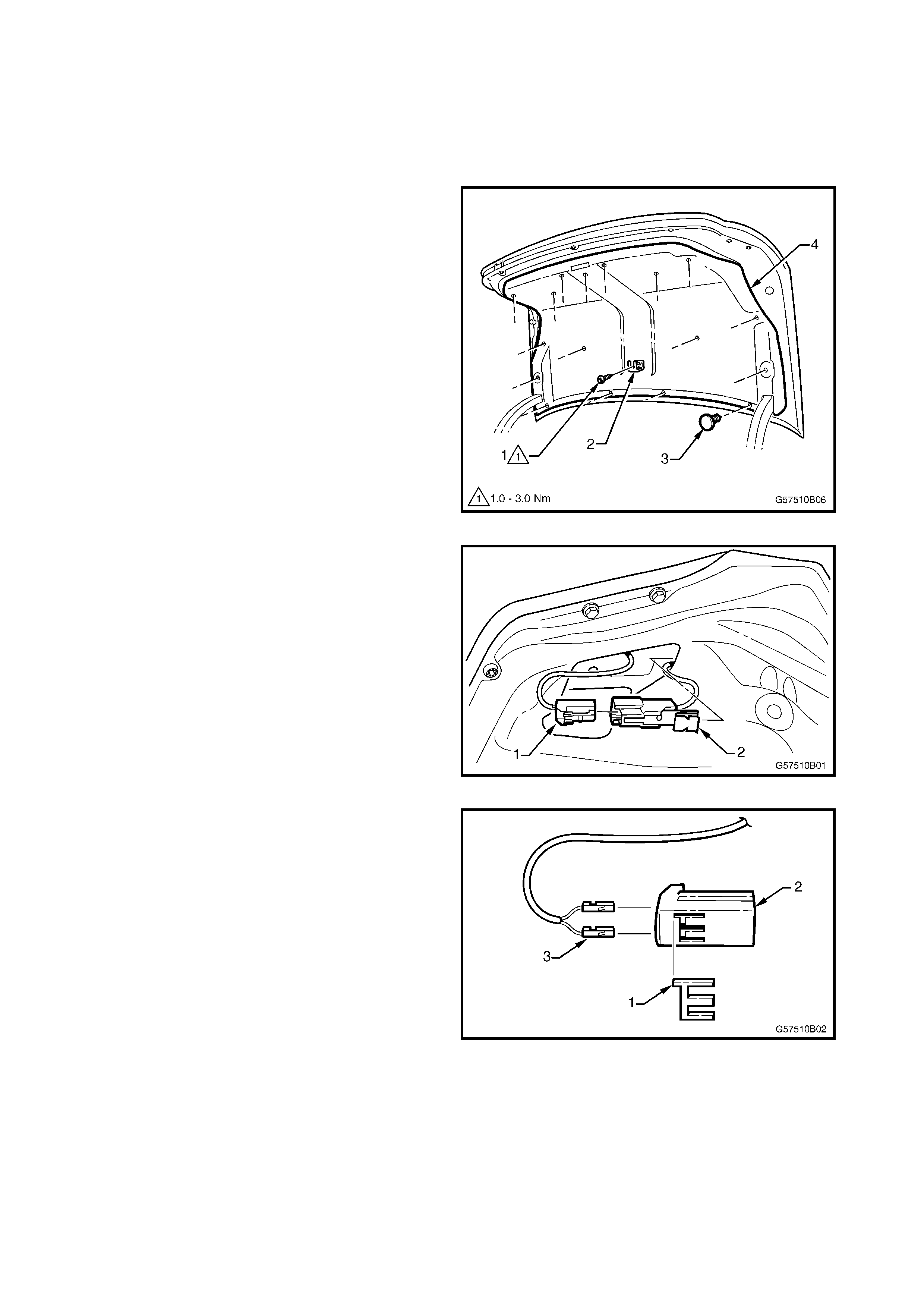
REMOVE
1. Remove the screw (1) attaching the spare wheel
stowage cover hook (2).
2. Using a suitable trim clip removal tool, remove the
retainers (3) attaching the decklid carpet (4), 17
places.
3. Remove the carpet from the decklid.
Figure 10B-1
4. Disconnect the spoiler high-mount stop lamp
connector (1) from the decklid harness connector
(2).
Figure 10B-2
5. Prise the retainer (1) from the high-mount stop
lamp connector (2) with a fine flat-blade
screwdriver and remove each wiring terminal (3).
Figure 10B-3
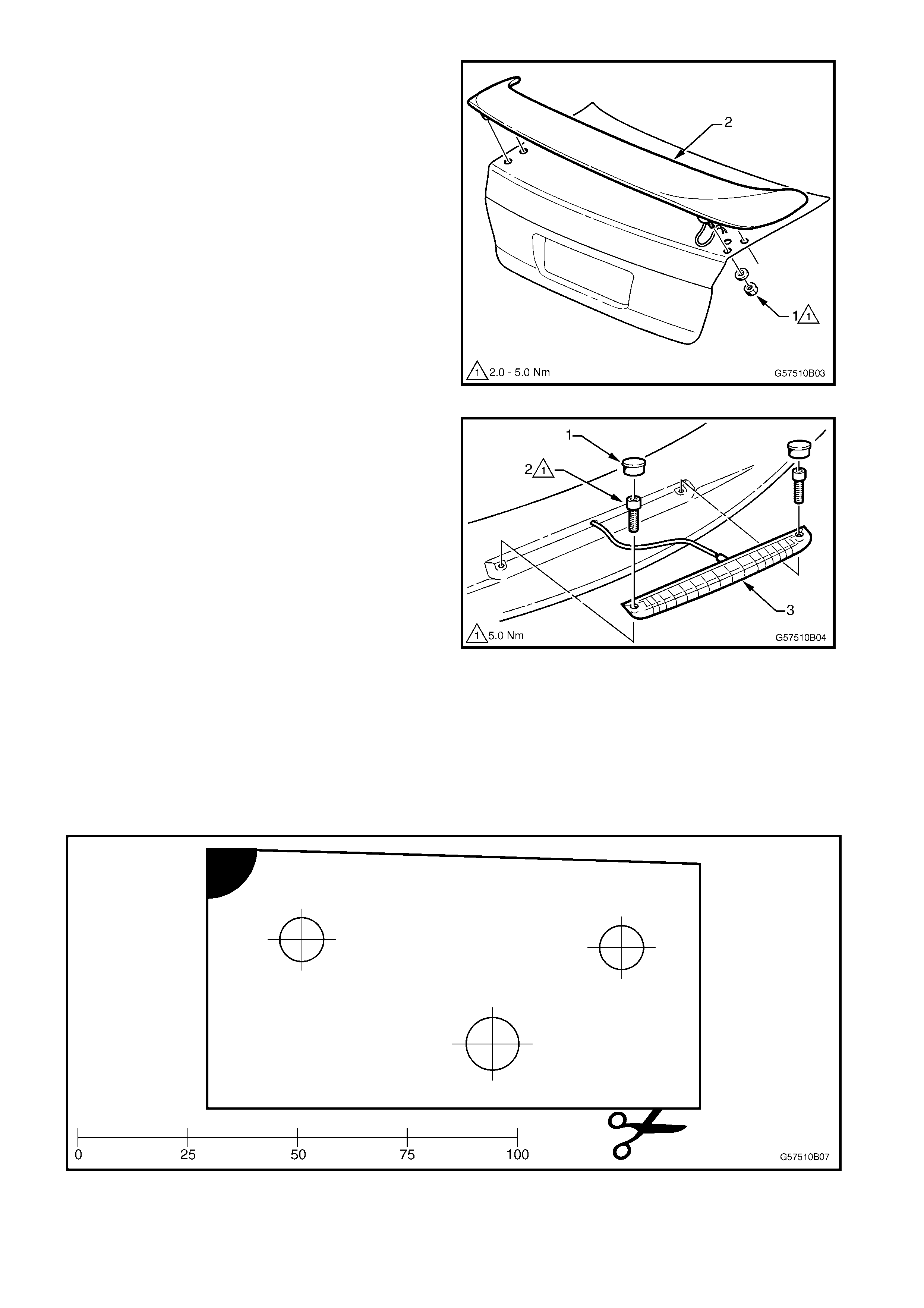
6. From the underside of the decklid, remove the nut
and washer (1), two places each side, attaching
the spoiler (2).
7. Remove the spoiler, withdrawing the wiring
harness from the RH side.
Figure 10B-4
8. If requir ed, pris e the s cr ew cap (1 ) and r emove the
screws (2) attaching the high-mount stop lamp
assembly (3) to the spoiler.
9. Remove the high-mount stop lamp, withdrawing
the harness from the spoiler cavity.
Figure 10B-5
INSTALL
NOTE: If the decklid has not been replaced, proceed
to Step 13.
1. Print and cut-out the drilling template provided in
Fig. 10B-6.
NOTE: Ensure it prints the correct size by comparing
the scale.
Figure 10B-6

2. Measure 400 mm from the front corner of the
decklid and mark each edge of the decklid, refer
Fig. 10B-7.
NOTE: The illustration is not to scale.
Figure 10B-7
3. Place the template on the right-hand edge of the
decklid as shown, aligning the front outer corner
(1) with the mark.
4. Mark the centre of the two mounting holes (2).
5. For the right-hand side only, mark the c entr e of the
wiring harness hole.
6. Turn the template over and align the front outer
corner with the mark on the left-hand side of the
decklid.
7. Mark the two mounting holes only.
8. Remove the template.
9. Sit the spoiler on the decklid and ensure the
mounting studs align with the marks. Adjust as
required.
10. Carefully drill the mounting holes. Initially drill 3
mm holes, followed by 10 mm holes.
11. Carefully drill the wiring harness hole on the right-
hand side only. Initially drill a 3 mm hole, and then
drill out to 12 mm.
12. Debur the drilled holes and apply primer to the
bare metal.
13. Install the high- m ount stop lam p onto the s poiler, if
removed and tighten the screws to the specified
torque, refer Fig. 10B-5.
HIGH-MOUNT STOP LAMP ATTACHING
SCREW TORQUE SPECIFICATION 5.0 Nm
14. Ensure the seals are correctly fitted onto the
spoiler.
15. Fit the spoiler onto the decklid, feeding the high-
mount stop lamp harness through its hole in the
decklid, refer Fig. 10B-4.
16. Fit the nuts and washers to the studs and hand
tighten.
17. Check alignment of spoiler on the decklid and
tighten the nuts to the specified torque.
18. Fit the high-mount stop lamp connector pins into
the connector body and refit the retainer, refer
Fig. 10B-3.
19. Connect the wiring connector and ensure it is
correctly clipped onto the decklid inner panel, refer
Fig. 10B-2.
20. Check the high-mount stop lamp operation.
21. Refit the decklid carpet, refer Fig. 10B-1.
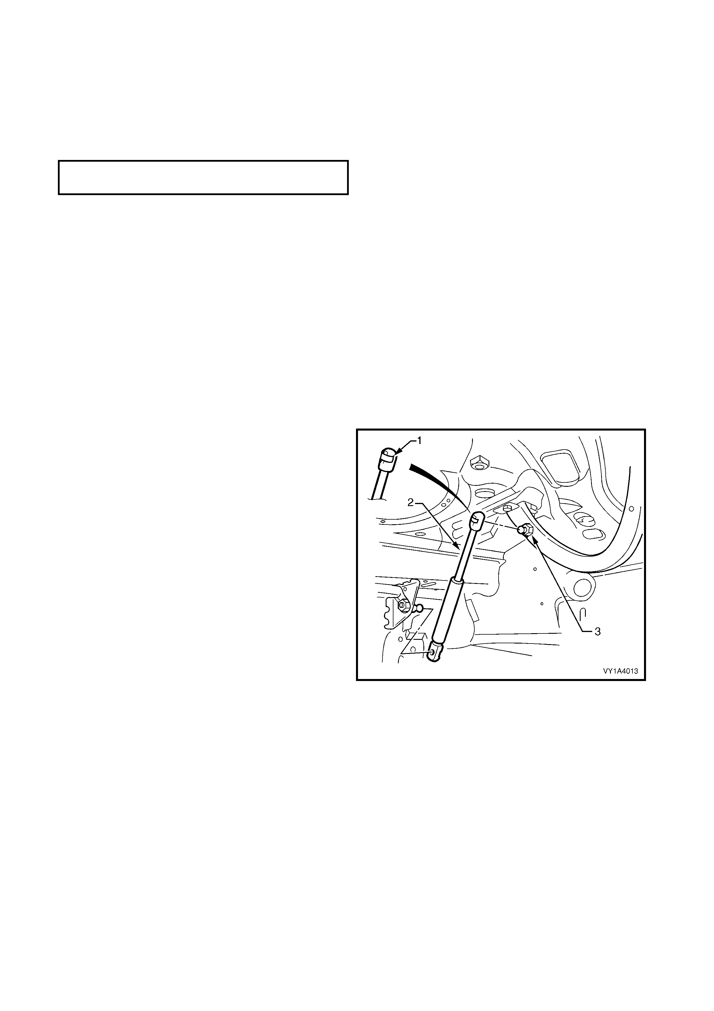
DECKLID GAS STRUT ASSEMBLY
Remove
1. Support the decklid securely.
2. Using a fine, flat blade screwdriver, prise the
retainer (1) from the gas strut end (2).
3. Pull the strut from the ball stud (3).
4. Repeat for the opposite end if required.
Reinstall
NOTE: Ensure the c orrec t type of gas strut is specified
for vehicles with a decklid spoiler.
1. Apply a small amount of lithium based grease to
the inside of the strut ball cup.
2. Install the retainer onto the strut end, if removed.
3. Align the strut with the ball stud and push into
place.
4. Repeat for the opposite end if required.
Figure 10B-8
DECKLID SPOILER ATTACHING NUT
TORQUE SPECIFICATION 2.0 - 5.0 Nm
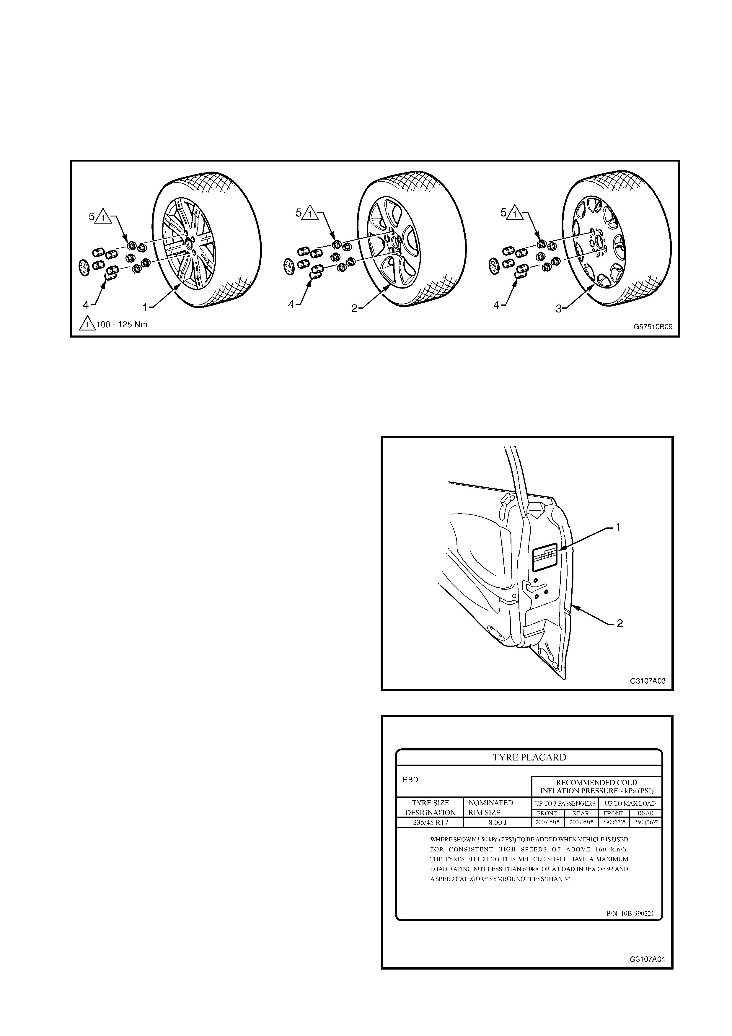
3.0 ALLOY WHEELS
Thr ee Holden By Design alloy wheel styles are available for V2 Series vehicles. T hey share the sam e diam eter and
width, but each has its own unique styling. The standard steel rim spare wheel remains fitted.
This Section of the Holden By Design Service Manual Supplement illustrates the wheel types available. For the
information required to service wheels for V2 Series vehicles, refer to Section 10 WHEELS & TYRES in the V2
Series Service Information.
Figure 10B-9
Legend
1. X - Series 8-spoke alloy wheel 17” x 8” 3. Wheel cap
2. Statesman International 6-spoke alloy wheel 17” x 8” 4. Wheel nut
3. Calais International alloy wheel 17” x 8”
When a Holden By Design alloy wheel and tyre
package is fitted, the standard tyre placard (1),
located on the end surf ace of the right-hand door ( 2),
is replaced with a new placard.
Figure 10B-10
The tyre placard provides information on the specific
tyre and wheel package fitted to the vehicle.
Figure 10B-11
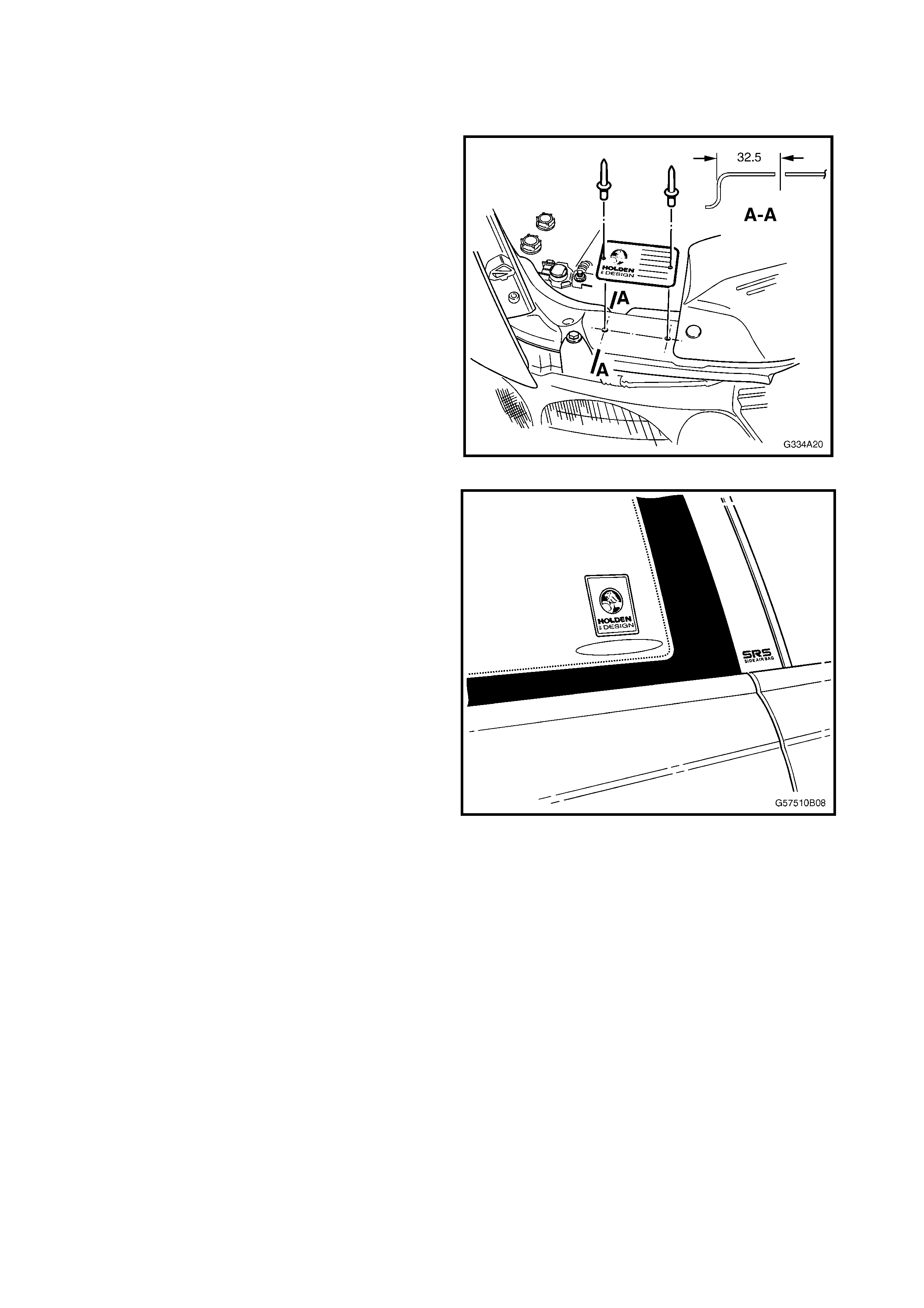
4.0 IDENTI FICATION & DECALS
Where a Holden By Design decklid spoiler has been installed, a HBD identification plate is installed on the front
upper panel in the engine compartment. A Holden By Design label is also placed on each side quarter glass.
1. Drill 3 m m holes to the dimensions shown into the
front upper panel.
2. Affix the identification plate with pop-rivets.
Figure 10B-12
The Holden By Design decal is affixed to each rear
quarter window as shown.
NOTE: Ensure the surface is clean and dry before
applying the decal.
Figure 10B-13

5.0 TORQUE WRENCH SPECIFICATIONS
Nm
Spare wheel stowage cover hook screw ...............................................1.0 – 3.0
High-mount stop lamp attaching screw ..........................................................5.0
Decklid spoiler attaching nut..................................................................2.0 – 5.0
Alloy wheel attaching nut ...............................................................110.0 – 140.0