
Holden By Design Options Page 12A–1
5-MAR-2003 Page 12A–1
Section 12A
VY Series Holden By Design (HBD) Options
ATTENTION
Before performing any Service Operation or other procedure described in this Section, refer to Section 00
WARNINGS, CAUTIONS AND NOTES for correct workshop practices with regard to safety and/or property
damage.
1 General Information............................................................................................................................... 2
2 Body Kits................................................................................................................................................ 5
2.1 Front Aprons – All Levels......................................................................................................................................5
Remove ...................................................................................................................................................................5
Reinstall ..................................................................................................................................................................6
2.2 Rear Apron, Level 1................................................................................................................................................7
Remove ...................................................................................................................................................................7
Reinstall ..................................................................................................................................................................7
2.3 Rear Apron, Wagon and Sedan, Levels 2 & 3...................................................................................................11
Remove .................................................................................................................................................................11
Reinstall ................................................................................................................................................................13
2.4 Rocker Panel Skirts..............................................................................................................................................16
2.5 Rear Lip Spoiler....................................................................................................................................................17
Remove .................................................................................................................................................................17
Reinstall ................................................................................................................................................................17
3 HBD Accessories................................................................................................................................. 20
3.1 Exhaust Extensions.............................................................................................................................................20
Remove .................................................................................................................................................................20
Reinstall ................................................................................................................................................................20
All Levels, Except Performance System...........................................................................................................20
Performance System........................................................................................................................................21
3.2 Wheel Packages...................................................................................................................................................22
Tyre Placards........................................................................................................................................................23
3.3 Pedal Pads............................................................................................................................................................24
Remove .................................................................................................................................................................24
Reinstall ................................................................................................................................................................24
3.4 Identification.........................................................................................................................................................25
Identification Plate ...............................................................................................................................................25
Remove............................................................................................................................................................25
Reinstall............................................................................................................................................................25
Rear Door Decals .................................................................................................................................................25
Remove............................................................................................................................................................25
Reinstall............................................................................................................................................................25
Rear Compartment Lid Emblem..........................................................................................................................26
Remove............................................................................................................................................................26
Reinstall............................................................................................................................................................27
4 Torque Wrench Specifications........................................................................................................... 28
Techline

Holden By Design Options Page 12A–2
5-MAR-2003 Page 12A–2
1 General Information
There are two levels of Holden By Design body kits available, a level one kit for SV8 Sedans, Executive and Acclaim
Sedans and Wagons and a level two kit for Berlina and Calais vehicles.
The rocker skirts use the same style for both levels, however the Wagon skirt is slightly longer with an extension that is
added to the Sedan skirt at production.
Holden By Design lower body kits are not available for the Ute series.
The front and rear bumper aprons and rocker skirts are painted in the vehicles body colour. The painting procedures are
relatively straight forward, providing the correct steps are followed for (PUR) Polyurethane.
Two rear spoilers are available for the Sedans, the MY 2003 VY S Series spoiler and a new rear lip spoiler.
The HBD Type 2 rear spoiler is the fitted to Commodore S spoiler. For Type 2 spoiler service information, refer to Section
1A4, 3.4 REAR SPOILER ASSEMBLY in the MY2003 VY and V2 Series Service Information.
The HBD Type 1 rear lip spoiler attaches to the rear edge of the sedan rear compartment lid with nuts and threaded
studs in the centre positions and screws in the outer edges. Urethane and double -sided tape is also used in the
reinstallation process.
The Holden By Design rear lip spoiler is painted in the vehicles body colour. The painting procedures are relatively
straight forward, providing the correct steps are followed for (PUR) Polyurethane.
The Holden By Design exhaust extensions fit over the original muffler tail pipe and are secured only by the interference
fit of the pipe to the extension.
Two styles of HBD exhaust extensions are available for the VY Series vehicles. The performance system series rear
muffler has dual round tips while other models receive the conventional design square opening.
Five alloy wheel and tyre packages are available as Holden By Design options for the VY Series vehicles, each has it’s
own unique styling, diameter and width. The standard steel rim is used for the spare.
The Holden By Design (HBD) alloy pedal pads for clutch and brake pedals replace the original slide on pad for the
standard MY 2003 VY and V2 Series vehicles.
The HBD alloy footrest is a direct replacement from the original, for service information refer to Section 1A8, 3.16,
DRIVER FOOTREST in the MY 2003 VY and V2 Series Service Information.
The HBD alloy throttle pedal is serviced by removing the pedal assembly and changing the pedal pad, for service
information refer to Section 6C1-3, 3.14 THROTTLE PEDAL ASSEMBLY in the MY 2003 VY and V2 Series Service
Information.
Where any of the Holden By Design options have been installed, a Holden By Design identification plate is riveted to the
front end panel assembly, decals are fitted to the rear door fixed glass on each sides and as a Holden By Design
emblem is fitted to the rear compartment lid or liftgate. No emblem is fitted to the Utility.
The Holden By Design identification plate is either engraved or stamped with the date, build number and the codes for
the Holden By Design options fitted to the vehicle.

Holden By Design Options Page 12A–3
5-MAR-2003 Page 12A–3
The following table contains a list of the Holden By Design (HBD) accessory options available for the MY 2003 VY
Sedans, Wagons and Utilities. Refer to the table for the appropriate reference to the service procedures.
“S” Pack Spoiler Refer to Section 1A9, 3.4 REAR SPOILER ASSEMBLY in
the MY 2003 VY and V2 Series Service Information.
Rear Lip Spoiler Refer to 2.5 REAR LIP SPOILER.
Exhaust Extensions Refer to 3.1 EXHAUST EXTENSIONS.
Leather Steering Wheel Refer to Section 9, 2.4 STEERING WHEEL ASSEMBLY in
the MY 2003 VY and V2 Series Service Information.
Satin Chrome Interior Door Handles Refer to Section 1A5, 2.5 FRONT DOOR INSIDE HANDLE
ASSEMBLIES in the MY 2003 VY and V2 Series Service
Information.
Stereo Upgrades Refer to Section 12D ENTERTAINMENT SYSTEMS in the
MY 2003 VY and V2 Series Service Information.
Wheel Packages Refer 3.2 WHEEL PACKAGES for identification. For
servicing procedures refer to Section 10 W HEELS AND
TYRES in the MY 2003 VY and V2 Series Service
Information.
FE2 Sports Suspension Refer to Section 3 FRONT SUSPENSION and 4A REAR
SUSPENSION in the MY 2003 VY and V2 Series Service
Information.
Stainless Steel Sill Plates Refer to VT & VT2 accessory fitting instruction: ROCKER
PANEL COVERS.
Leather Auto Gear Knob Refer to Section 7C4-3.3 SELECTOR CONTROL LEVER
ASSEMBLY in the MY 2003 VY and V2 Series Service
Information.
Leather Manual Gear Knob Refer to Section 7B1 3.3 GEARSHIFT LEVER KNOB AND
BOOT ASSEMBLY in the MY 2003 VY and V2 Series
Service Information.
Leather Handbrake Handle Refer to Section 5A, PARK BRAKE LEVER in the MY
2003 VY and V2 Series Service Information.
Alloy Foot Pedals For Throttle Pedal refer to Section 6C1-3, 3.14 THROTTLE
PEDAL ASSEMBLY in the MY 2003 VY and V2 Series
Service Information.
For clutch and brake pedals, refer 3.3 PEDAL PADS.
V8 “Performance” Exhaust System Refer to Section 8B EXHAUST SYSTEM in the MY 2003
VY and V2 Series Service Information.
LPG Refer to Section 8A2 LPG SYSTEM in the MY 2003 VY
and V2 Series Service Information.
Lower Body Kits Refer 2.0 BODY KITS.
V6 Cruise Cont rol Refer to Section 12E CRUISE CONTROL V6 in the
MY2003 VY and V2 Series Service Information.
Hand Controls Refer to Section 4J HAND CONTROLS in the Holden By
Design Supplement.
Satellite Navigation Refer to Section 12L NAVIGATION SYSTEM in the MY
2003 VY and V2 Series Service Information.
Rear Cargo Barrier Refer to Holden By Design, Section 4F, 3 WAGON
CARGO BARRIER in the Holden By Design Supplement.
Hard Tonneau Cover Refer VU ACCESSORY FITTING INSTRUCTIONS,
Tonneau Cover Hard Top.
Soft Tonneau Covers Refer VU ACCESSORY FITTING INSTRUCTION, Soft
Tonneau Cover.
Holden By Design Options Page 12A–4
5-MAR-2003 Page 12A–4
Sunroof Refer to Section 1F1 SUNROOF in the MY 2003 VY and
V2 Series Service Information.
Roo Bar Refer to Holden By Design Supplement, Section 4F, 2
ROO BAR in the Holden By Design Supplement.
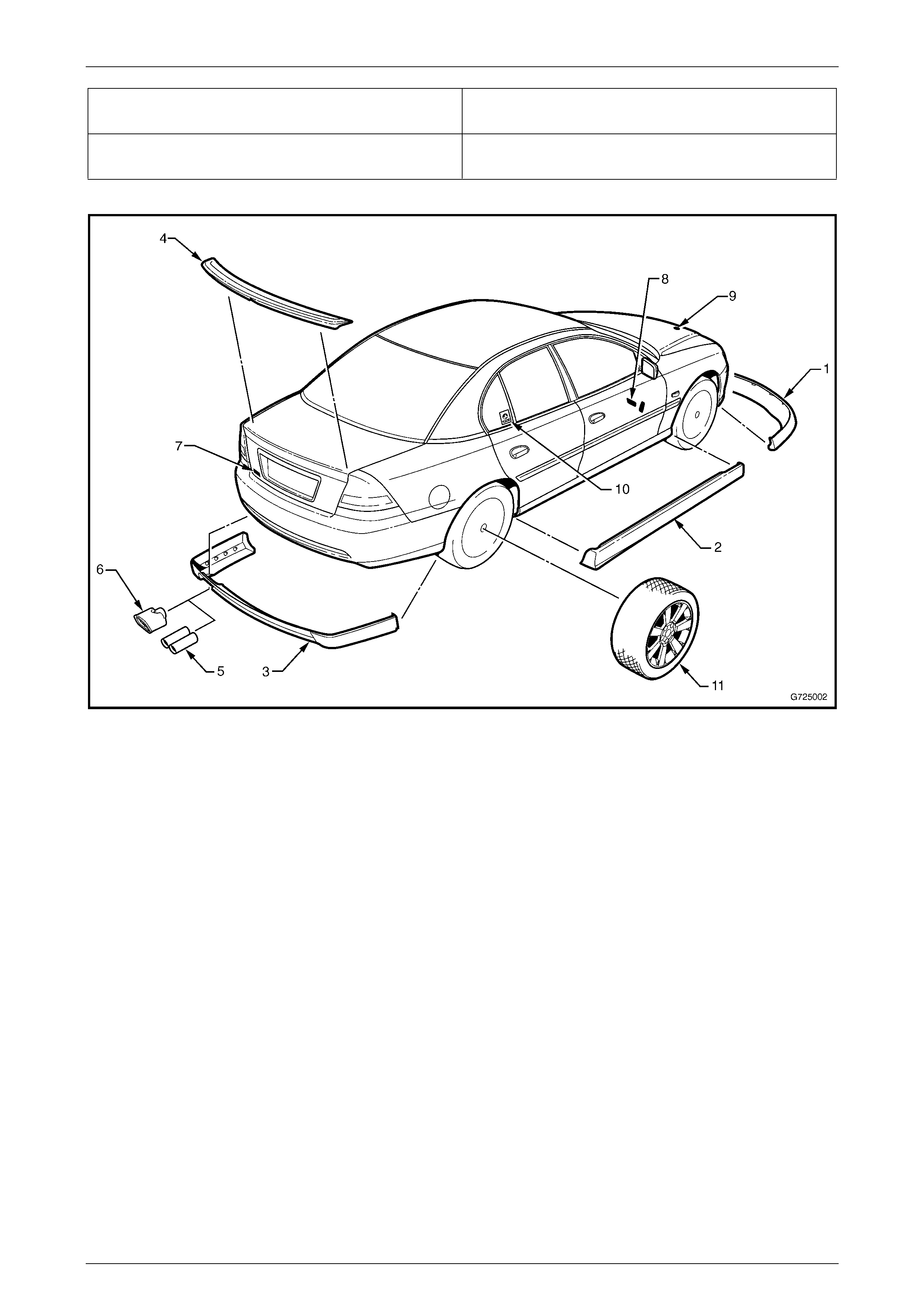
Figure 12A – 1 shows the Holden By Design components described in this Supplement.
Figure 12A – 1
Legend
1 Front Bumper Apron
2 Rocker Panel Skirt
3 Rear Bumper Apron
4 Rear Lip Spoiler
5 Dual Exhaust Extensions (Performance S ystem)
6 Exhaust Extension without performance exhaust system.
7 HBD Badge
8 Alloy Pedals
9 HBD ID Plate
10 HBD Decal
11 Wheel / Tyre Package
Holden By Design Options Page 12A–5
5-MAR-2003 Page 12A–5
2 Body Kits
2.1 Front Aprons – All Levels
NOTE
Although there are physical differences between
the two levels of front aprons available, the
service procedures are the same with the
exception of an extra screw securing the apron to
the fascia and also the removal of the Lower
radiator grille for levels 2.
Remove
1 Remove the front bumper fascia, refer to Section 1D, 2.2 FRONT BUMPER FASCIA ASSEMBLY in the MY 2003
VY and V2 Series Service Information.
2 Place the bumper fascia assembly upside down on a clean soft surface.
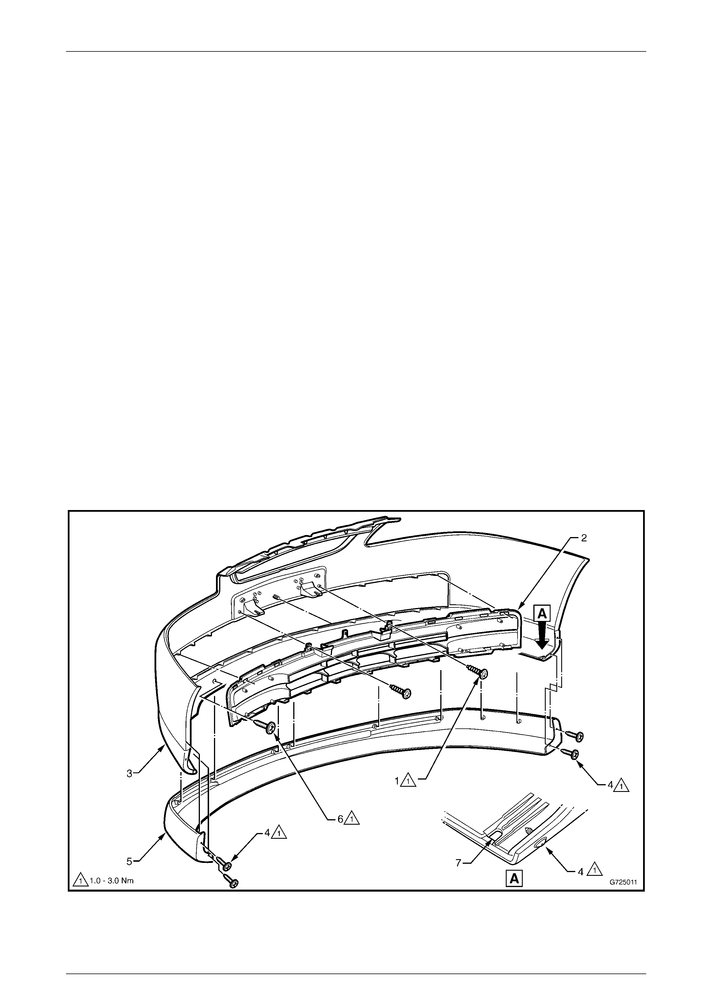
3 Referring to Figure 12A – 2 remove the following:
a For level 2 aprons, remove the two screws (1) attaching the lower grille (2) to the bumper fascia (3).
b Unclip the lower grille and remove.
c Remove the two screws (4) securing each end of the apron (5) to the fascia.
d Remove the screw (6) eleven places for level one, or the ten places for level two, from behind the fascia
securing the front apron.
e Unclip the outer edges and then gently pull the apron from the fascia.
Figure 12A – 2
Holden By Design Options Page 12A–6
5-MAR-2003 Page 12A–6
Reinstall
1 If the bumper fascia has not been replaced, proceed to step 12.
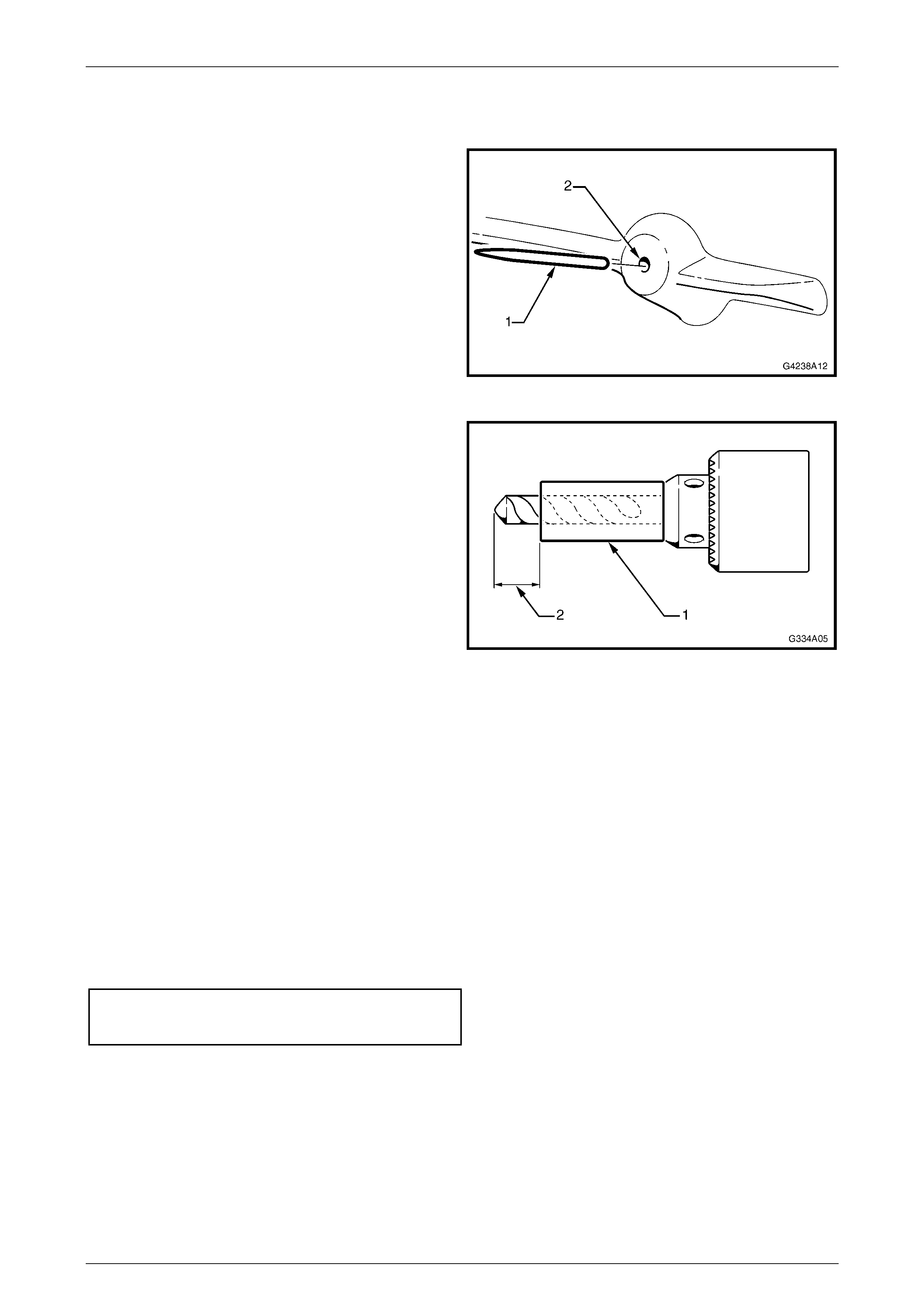
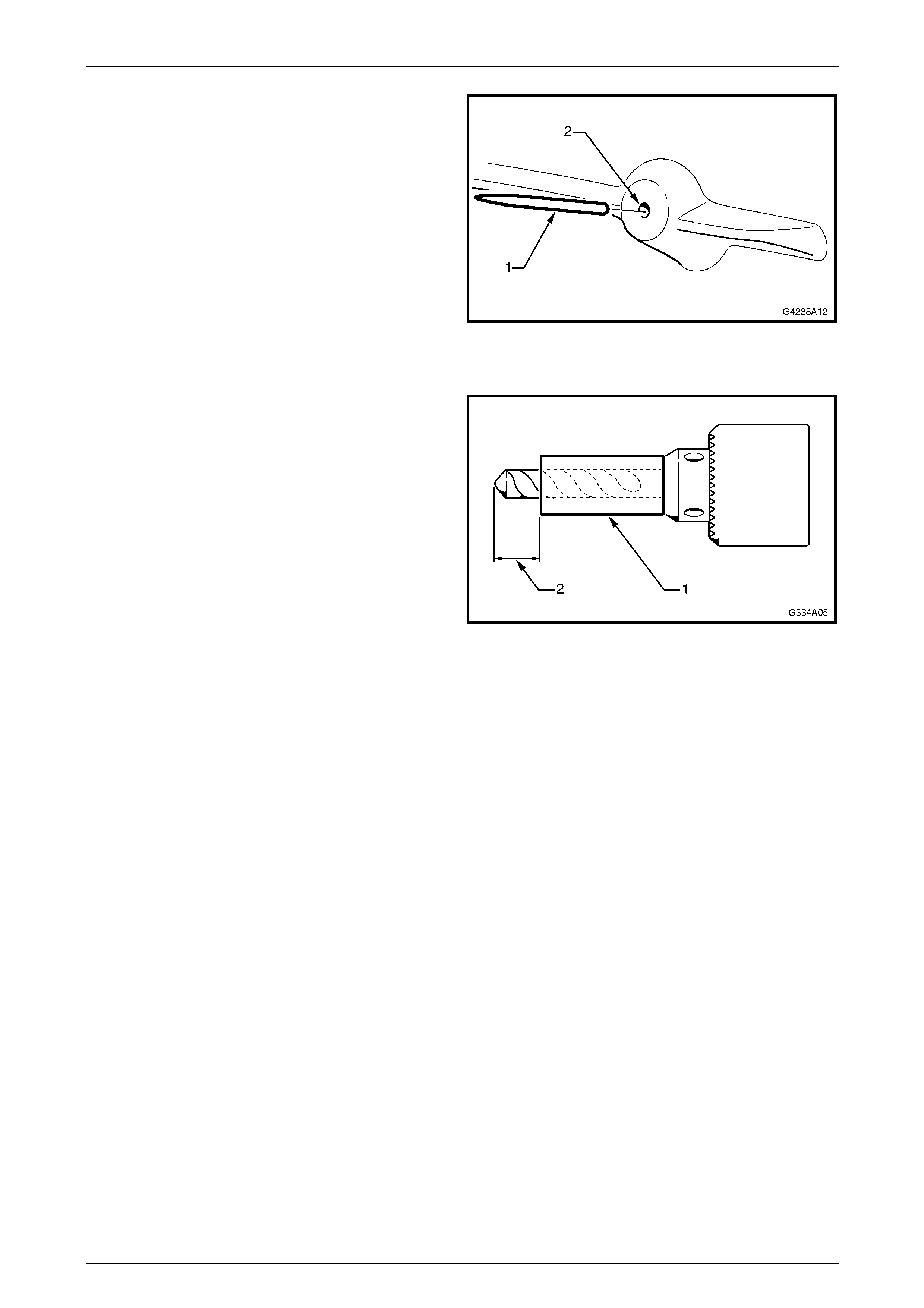
2 Manufacture the required amount of pins (1) from a
length of bronze welding wire or similar material. The
pins are to be 9 to 10 mm in length and no larger than
2.5 mm in diameter.
3 Using a grinder, sharpen a point on one end of the pin.
NOTE
Although Holden By Design bumper aprons are
supplied with the screw bosses pre-drilled. To
ensure that the pins will fit as required, steps 4 &
5 will still need to be completed.
Figure 12A – 3
4 Cut a length of tube (1) to fit over a drill bit to restrict
the drill tip depth. The size of the drill bit is to be the
same size of the pins manufactured in step 2. The
length of the drill bit from the top of the tube to the tip
of the drill bit (2) is to be 8 mm.
5 Drill a 2.5 mm hole centrally in each screw boss on the
rear side of the front bumper apron to a depth of 8
mm.
6 Insert the pins into each of the screw boss’s with the
point of the pin protruding above the surface of the
boss approximately 1 – 2 mm.
7 With the aid of an assistant carefully place the apron
onto the bumper fascia in the correct position.
8 At each screw boss, tap on the bumper apron and
fascia to ensure that each pin clearly marks the fascia.
This mark will be the point where the screw holes
securing the front apron to the fascia will be drilled.
Figure 12A – 4
9 Carefully remove the apron from the fascia.
10 Drill the fascia at the points marked in step 8 to 7mm in diameter.
11 Remove the pins from the front bumper apron.
12 Fit the front apron onto the bumper fascia.
13 Referring to Figure 12A – 2, reinstall the bumper apron on to the fascia following the steps below:
a From the rear of the fascia, reinstall the screw (6) eleven places for level one or ten places for level two and
tighten to the specified torque.
b Reinstall the screw (6), two places each end of the front apron securing the apron ends to the fascia and
tighten to the specified torque.
Fascia to apron screw............................... 1.0 – 3.0 N.m
Bumper apron end screw..........................1.0 – 3.0 N.m
c For level 2 aprons reinstall the lower grille (1), (level two aprons only).
d From the rear of the fascia drill a 6 mm hole (7) each side through the apron for the lower screw, using the
fascia as a template, refer Figure 12A – 2 View A.
e From underneath the fascia, enlarge the hole to 12 mm through the apron only (2) this will allow the lower
mounting screw head to clear the apron.
19 Reinstall the bumper bar fascia and apron assembly, refer to Section 1D, 2.2 FRONT BUMPER FASCIA
ASSEMBLY in the MY 2003 VY and V2 Series Service Information.
Holden By Design Options Page 12A–7
5-MAR-2003 Page 12A–7
2.2 Rear Apron, Level 1
Remove
1 Remove the rear bumper fascia, refer to Section 1D, 2.5 REAR BUMPER FASCIA ASSEMBLY in the MY 2003 VY
and V2 Series Service Information.
2 Place the fascia assembly upside down on a clean soft surface.
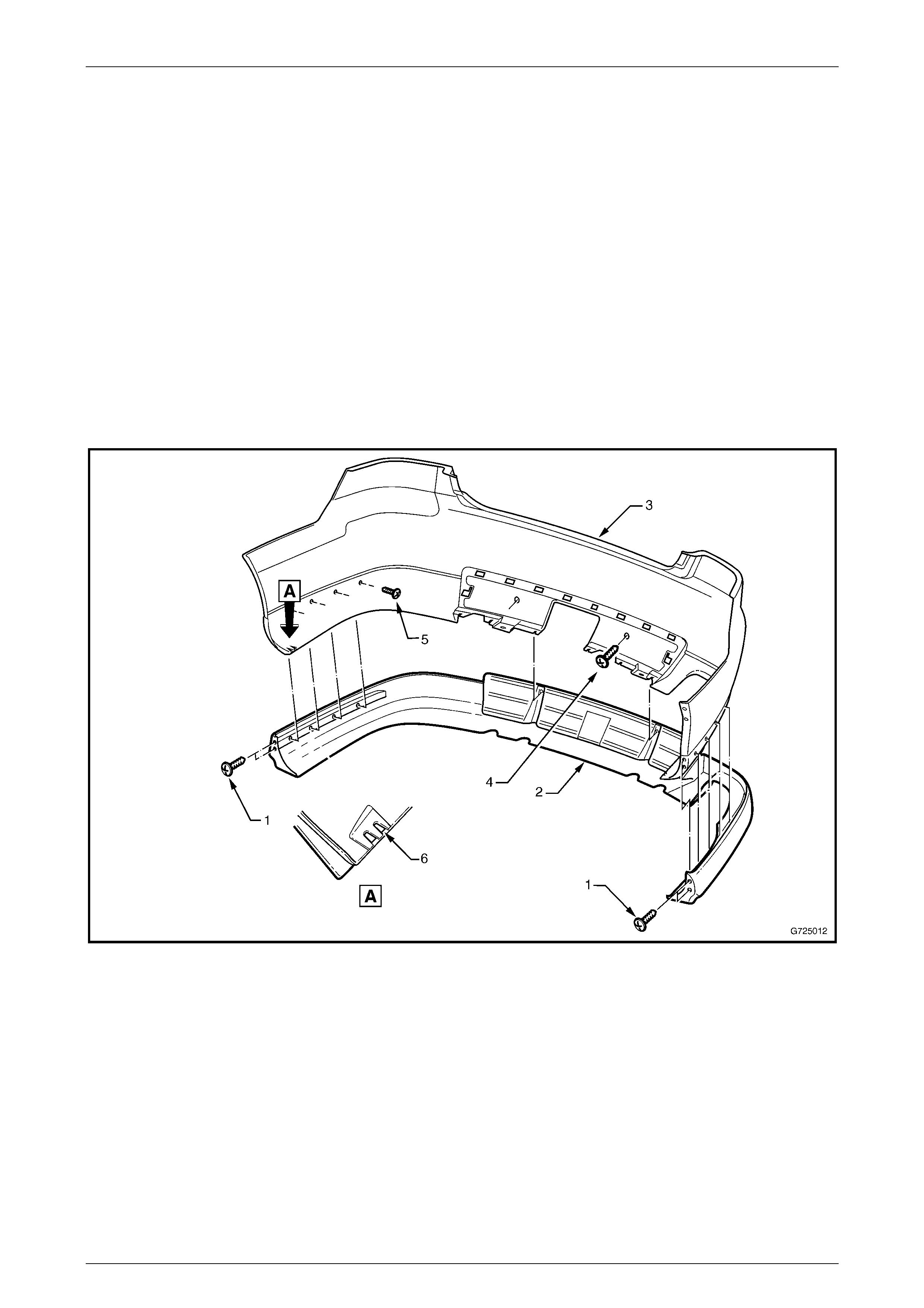
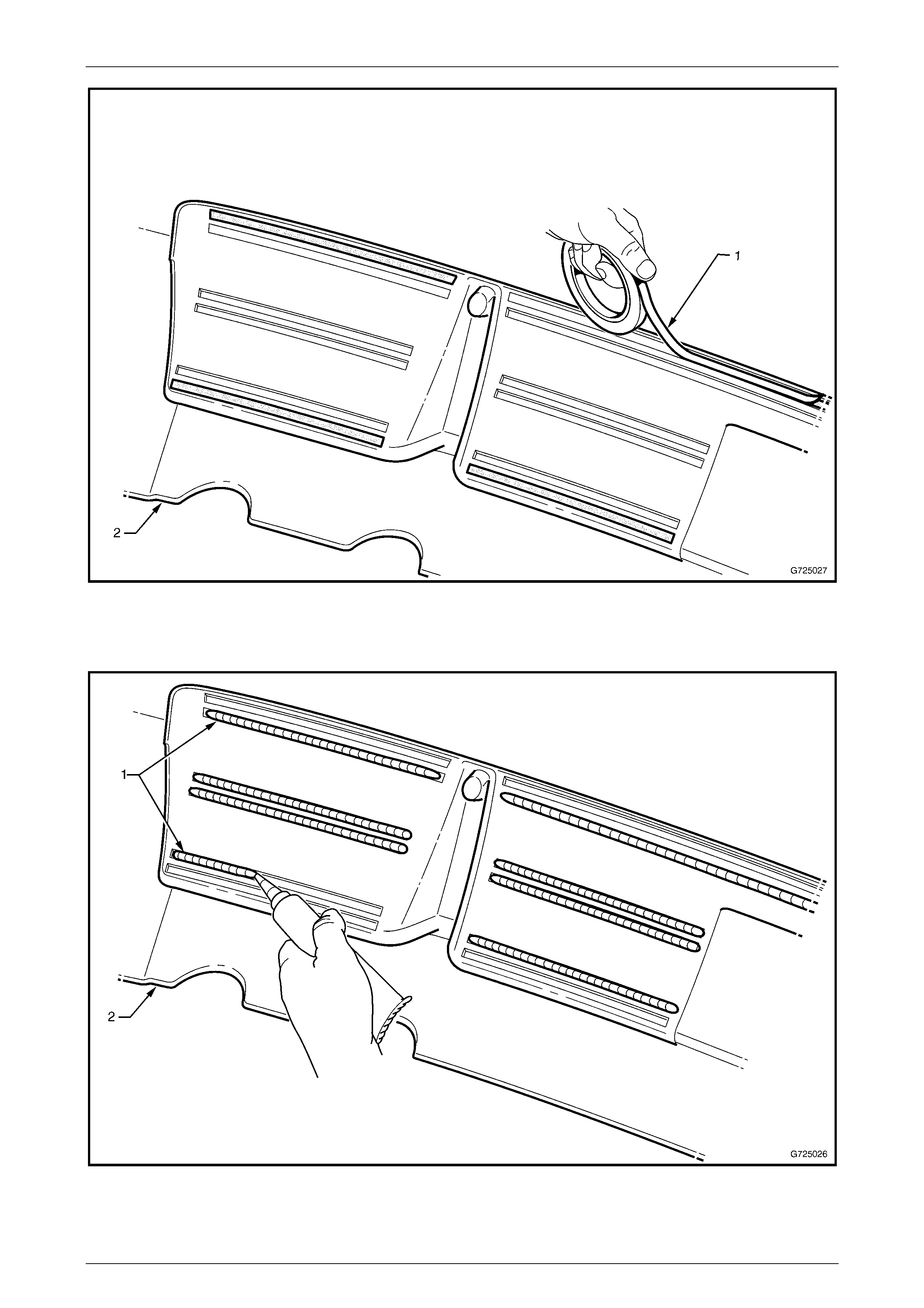
3 Referring to Figure 12A – 5 remove the apron from the facia following the steps below:
a Remove to two screws each side (1) securing each end of the rear apron (2) to the fascia (3).
b Remove the screw (4), two places, securing the rear bumper apron to the bumper fascia.
c Remove the screw (5) four places each side, securing the apron to the fascia.
d Carefully pull on the apron to dislodge the urethane and double sided tape. If required use a knife or similar
object to help cut through the urethane and tape.
e Remove the rear apron from the fascia.
Figure 12A – 5
Reinstall
If the bumper fascia has not been replaced, proceed to step 10.
Holden By Design Options Page 12A–8
5-MAR-2003 Page 12A–8
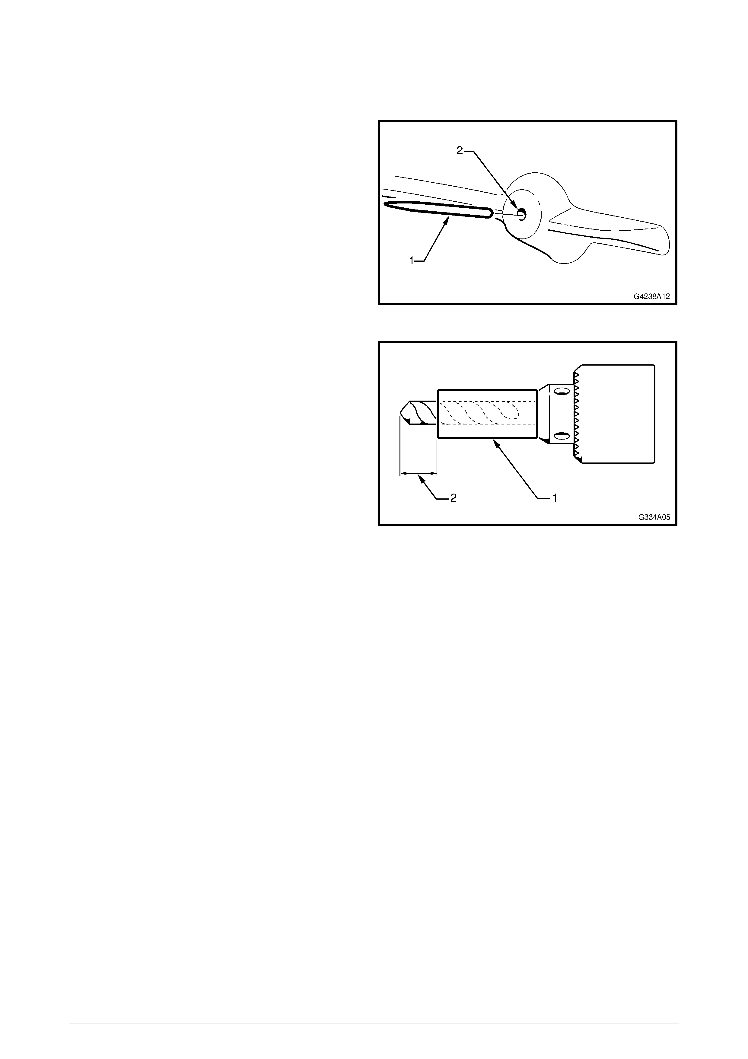
1 Manufacture the required amount of pins (1) from a
length of bronze welding wire or similar material. The
pins are to be 9 to 10 mm in length and no larger than
2.5 mm in diameter.
2 Using a grinder sharpen a point on one end of the pin.
NOTE:
Holden By Design bumper aprons are supplied
with the screw bosses pre-drilled. To ensure that
the pins will fit as required, steps 4 & 5 will still
need to be completed.
Figure 12A – 6
3 Cut a length of tube (1) to fit over a drill bit to restrict
the drill tip depth. The size of the drill bit is to be the
same size of the pins manufactured in step 2. The
length of the drill bit from the top of the tube to the tip
of the drill bit (2) is to be 8 mm.
Figure 12A – 7
4 Drill a 2.5 mm hole centrally in each screw boss on the rear side of the bumper apron.
5 Insert the pins into each of the screw bosses with the point of the pin protruding above the surface of the screw
boss approximately 1 – 2 mm.
6 With the aid of an assistant carefully place the rear apron onto the bumper fascia.
7 At each screw boss, tap on the bumper apron and fascia to ensure each pin clearly marks the fascia. This mark will
be the point where the screw holes securing the rear bumper apron to the fascia will be drilled.
8 Carefully remove the rear bumper apron from the fascia.
9 Drill the fascia at the points marked to 7mm in diameter.
10 Remove the pins from the rear bumper apron.
11 If either the fascia or the bumper apron has not been replaced, clean of any residual urethane or double sided tape.
12 Apply double-sided tape (1), (3M or similar with a dimension of 6.0 x 1.0mm) to the rear apron at the locations
shown, refer to Figure 12A – 8.
Holden By Design Options Page 12A–9
5-MAR-2003 Page 12A–9
Figure 12A – 8
13 Apply a bead of urethane adhesive (1) (Wurth Bond+Seal or similar) at the locations shown, refer to
Figure 12A – 9.
Figure 12A – 9

Holden By Design Options Page 12A–10
5-MAR-2003 Page 12A–10
14 Fit the rear apron onto the bumper bar fascia.
15 Referring to Figure 12A – 5 assemble the apron to the facia in the following order.
a From the rear of the fascia reinstall the screw (4), two places across the back in the insert area.
b Install the screw (5), four places each side.
c Reinstall the screw (1), two places at each end of the apron.
d Tighten all screws to the specified torque.
Fascia to apron screw............................... 1.0 – 3.0 N.m
Bumper apron end screw..........................1.0 – 3.0 N.m
16 From the rear of the fascia drill a 6mm hole (6) each side, through the apron for the lower screw, using the fascia
as a template, refer to Figure 12A – 5 View A.
17 From underneath the fascia drill a 12mm hole through the apron only, this will allow the lower mounting screw head
to clear the apron.
18 Reinstall the bumper fascia, refer to Section 1D, 2.5 REAR BUMPER FASCIA ASSEMBLY in the MY 2003 VY and
V2 Series Service Information.

Holden By Design Options Page 12A–11
5-MAR-2003 Page 12A–11
2.3 Rear Apron, Wagon and Sedan,
Levels 2 & 3
Although there are physical differences between the Wagon and Sedan Levels 2 & 3 rear aprons, the installation
procedure is the same for both.
Remove
1 Remove the rear bumper fascia assembly, refer to Section 1D, 2.5 REAR BUMPER FASCIA ASSEMBLY Sedan
and refer to Section 1D, 2.6 REAR BUMPER FASCIA ASSEMBLY Wagon in the MY 2003 VY and V2 Series
Service Information.
2 Place the bumper fascia assembly upside down on a clean soft surface.
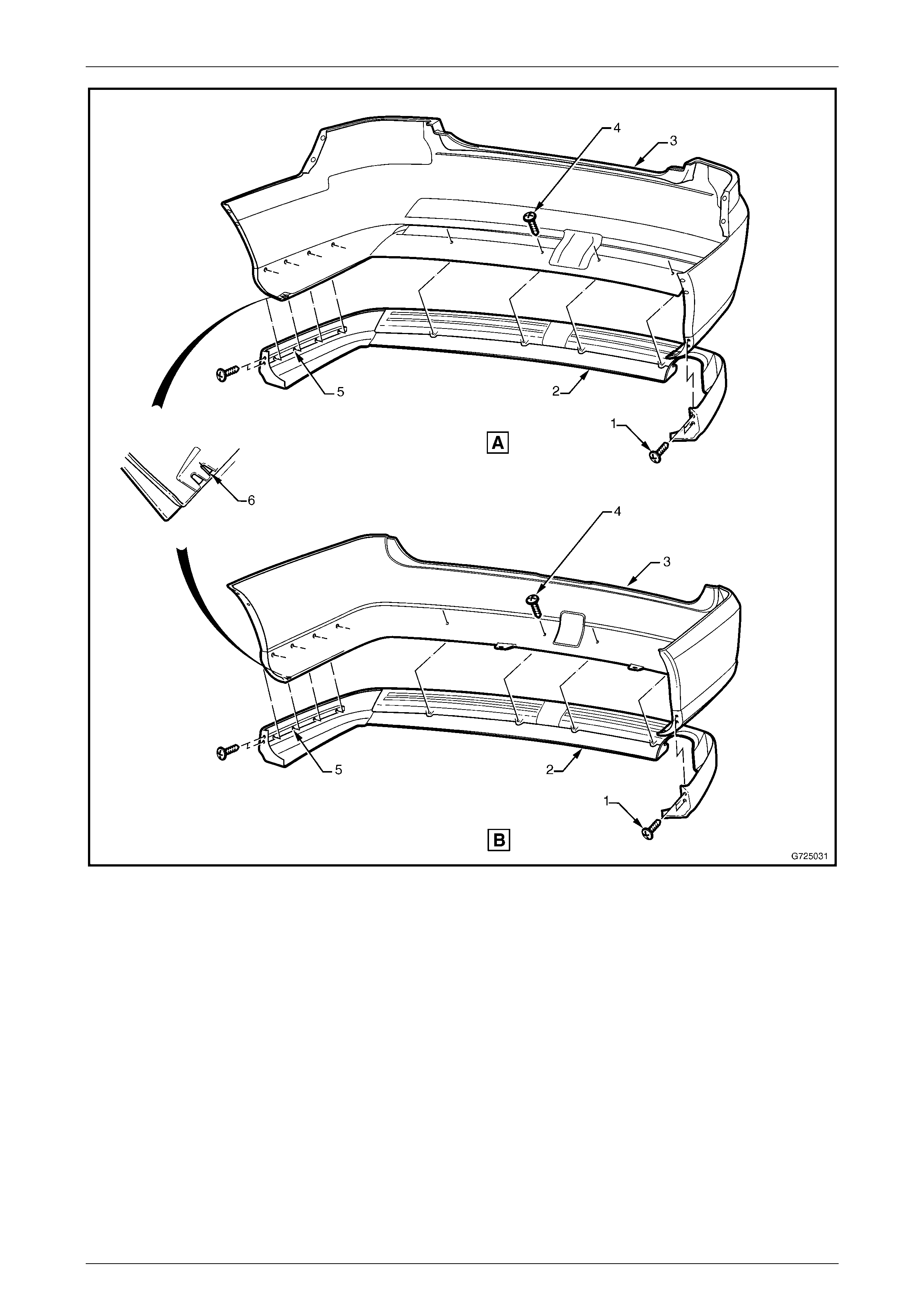
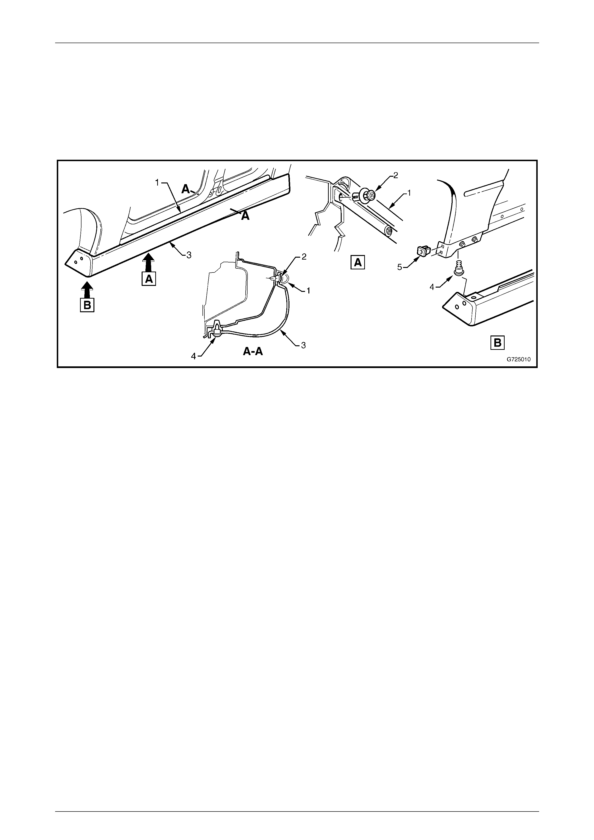
3 Referring to Figure 12A – 10, View A for Sedan and View B for Wagon, remove the apron following the steps:
a Remove the two screws (1) two places securing each end of the rear apron (2) to the bumper fascia (3).
b Remove the screw (4), four places along each side and four places along the rear of the bumper fascia
securing the apron to the fascia.
c Carefully pull on the apron to dislodge the urethane adhesive and double sided tape, if required use a knife or
similar object to help cut through the urethane tape.
4 Remove the rear apron from the fascia.
Holden By Design Options Page 12A–12
5-MAR-2003 Page 12A–12
Figure 12A – 10
Holden By Design Options Page 12A–13
5-MAR-2003 Page 12A–13
Reinstall
1 If the bumper fascia has not been replaced, proceed to step 13.
3 Manufacture the required amount of pins from a length
of bronze welding wire or similar material. The pins are
to be 9 to 10 mm in length.
4 Using a grinder sharpen a point on one end of the pin.
NOTE
Holden By Design aprons are supplied with the
screw bosses pre-drilled. To ensure that the pins
will fit as required, steps 5 & 6 will still need to be
completed.
Figure 12A – 11
5 Cut a length of tube (1) to fit over a drill bit to restrict
the drill tip depth. The size of the drill bit is to be the
same size of the pins manufactured in step 2. The
length of the drill bit from the top of the tube to the tip
of the drill bit (2) is to be 8 mm.
6 Drill a hole 2.5mm centrally in each screw boss on the
rear side of the rear apron.
Figure 12A – 12
7 Insert the pins into each screw boss with the point of the pin protruding above the surface of the boss
approximately 1 – 2mm.
8 With the aid of an assistant carefully place the rear apron onto the bumper fascia.
9 At each screw boss, tap on the rear apron and fascia to ensure each pin clearly marks the fascia. This mark will be
the point where the screw holes securing the apron to the fascia will be drilled.
10 Carefully remove the rear apron from the fascia.
11 Remove the pins from the apron.
12 Drill the fascia at the points marked to 7mm in diameter.
13 If either the fascia or the apron has not been replaced, clean of any residual urethane and double sided tape form
the part that is not being replaced.
14 Apply two strips of double sided tape (1) (3M or similar with dimensions of 6.0 x 1.0mm) to the rear apron, refer to
Figure 12A – 13.
Holden By Design Options Page 12A–14
5-MAR-2003 Page 12A–14
Figure 12A – 13
15 Apply a bead of urethane adhesive (1) (Wurth Bond+Seal or similar) refer to Figure 12A – 14.
Figure 12A – 14
16 Fit the rear bumper apron onto the bumper fascia.
17 Reinstall the screw (4), four places along each side of the bumper apron and four places securing the rear bumper
apron to the fascia.
18 Reinstall the screw (1), two places at each end of the rear apron securing the apron to the fascia.
19 Tighten all screws to the specified torque.
Fascia to apron screw............................... 1.0 – 3.0 N.m
Bumper apron end screw..........................1.0 – 3.0 N.m
20 From the rear of the fascia drill a 6mm hole each side (6) using the fascia as a template, through the apron, refer
Figure 12A – 10.
21 From underneath the apron drill a 12mm hole through the apron only, this will allow the lower mounting screw head
to clear the apron for the lower screw.

Holden By Design Options Page 12A–15
5-MAR-2003 Page 12A–15
NOTE
To ensure the fascia and the apron are matched
tightly together it is recommended that the apron
be taped to the fascia until the urethane has
cured. This can take up to 12 hours depending on
temperature and brand of urethane used.
22 Reinstall the bumper fascia, refer to Section 1D, 2.5 REAR BUMPER FASCIA ASSEMBLY, Sedan or refer to
Section 1D, 2.6 REAR BUMPER FASCIA ASSEMBLY, Wagon in the MY 2003 VY and V2 Series Service
Information.
Holden By Design Options Page 12A–16
5-MAR-2003 Page 12A–16
2.4 Rocker Panel Skirts
Holden By Design rocker panel skirt removal and reinstallation procedures carry over from the MY 2003 VY and V2
series vehicles. For information not found in this section, refer to Section 1A9, 5.9 ROCKER PANEL MOULDING
ASSEMBLY in the MY 2003 VY and V2 Series Service Information.
The rocker panel skirts are painted in the vehicles body colour. The painting procedures are relatively straight forward,
providing the correct steps are followed for Polypropylene materials.
Figure 12A – 15
Holden By Design Options Page 12A–17
5-MAR-2003 Page 12A–17
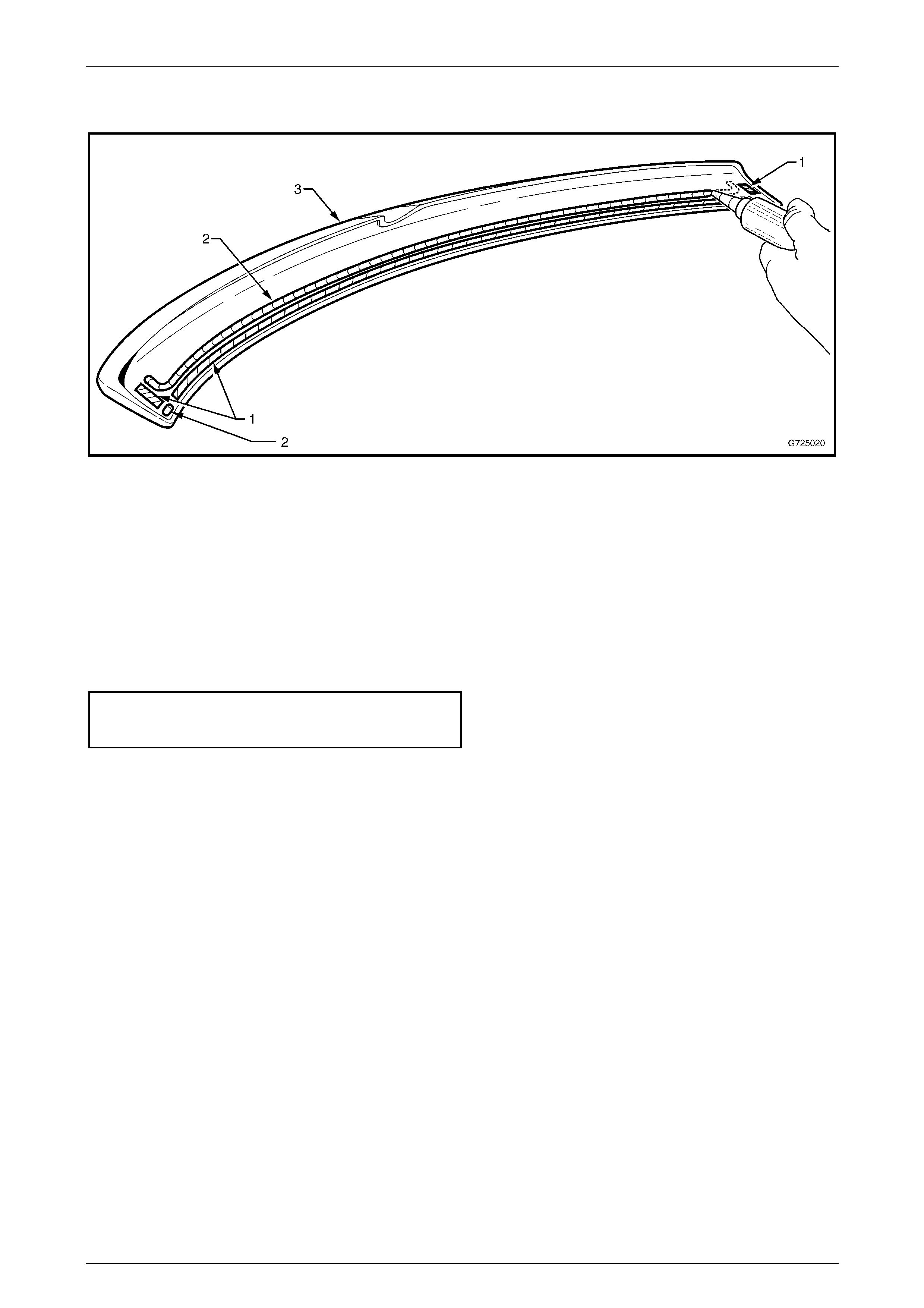
2.5 Rear Lip Spoiler
Remove
1 Open the rear compartment lid and remove the rear compartment lid carpet if fitted, refer to Section 1A4, 3.1 REAR
COMPARTMENT LID CARPET in the MY2003 VY and V2 Series Service Information.
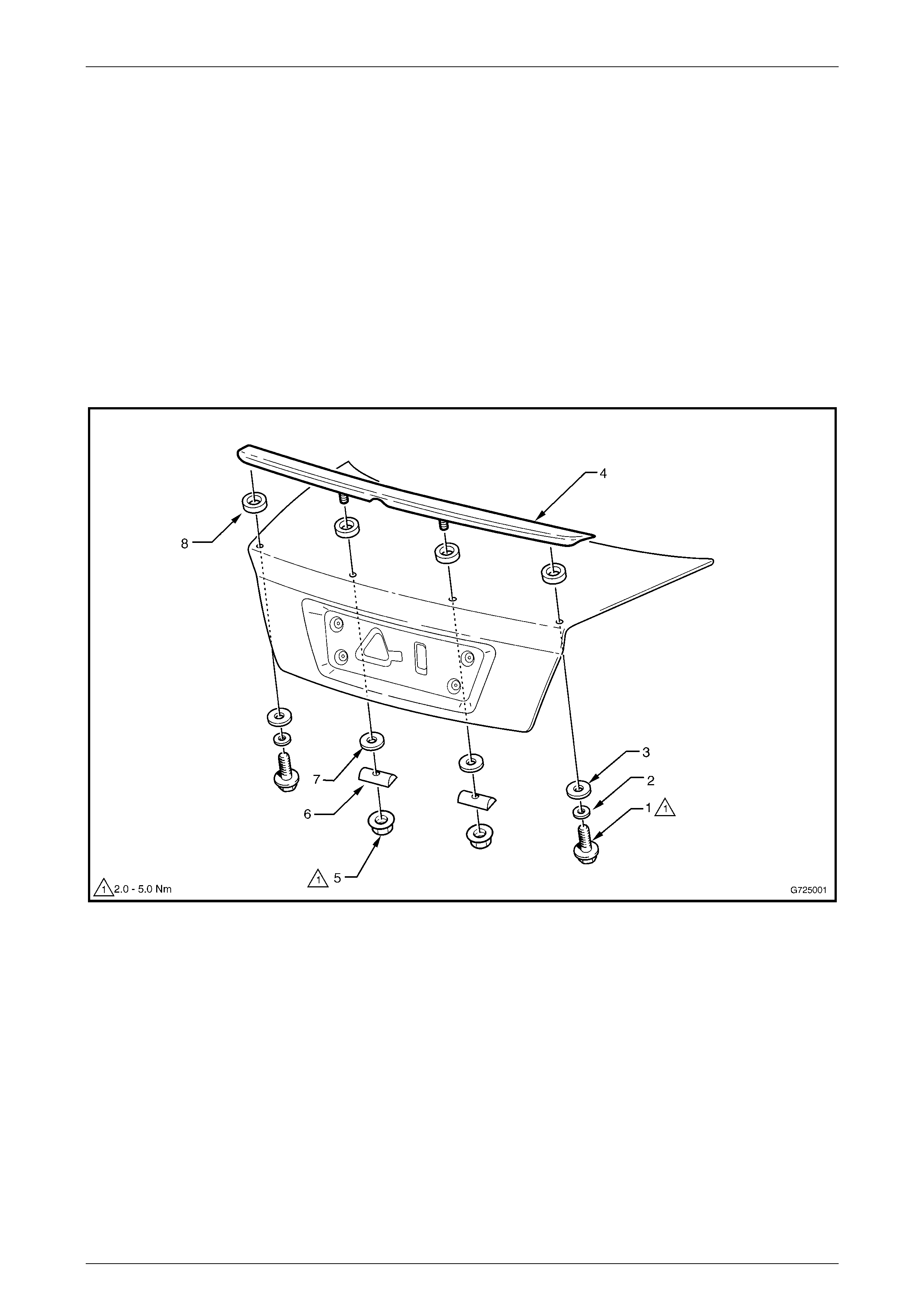
2 Referring to Figure 12A – 16 remove the rear lip spoiler in the following order:
a Remove the screw (1) washer (2) and seal (3) one place each side, attaching the spoiler (4) to the rear
compartment lid .
b From within the rear compartment lid cavity, remove the nut (5) spacer (6) seal (7) one place each side,
attaching the spoiler (4) to the rear compartment lid.
3 Rock the spoiler back and forth slightly to release the urethane and double sided tape.
4 Remove the lip spoiler from the vehicle.
Figure 12A – 16
Reinstall
1 If the rear compartment lid has not been replaced, proceed to step 9.
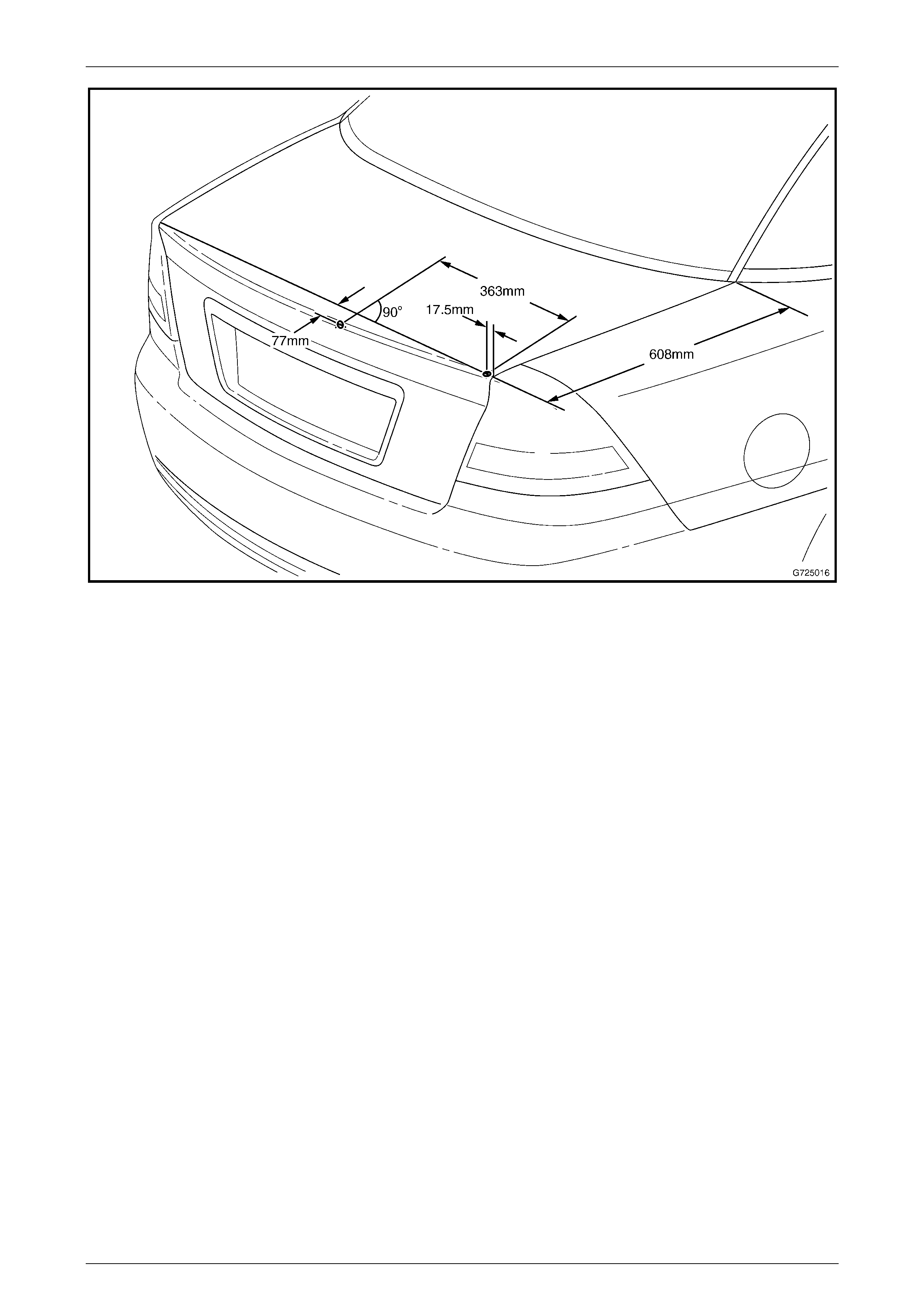
2 Following the steps below and using the dimensions in Figure 12A – 17, mark out the holes to be drilled for the
spoiler mounts.
3 Measure down from the forward edge of the rear compartment lid 608 mm on each side and draw a line across the
width of the rear compartment lid.
4 Using the measurements in Figure 12A – 17, mark out the locations for the holes to be drilled on the right-hand
side of the rear compartment lid.
Holden By Design Options Page 12A–18
5-MAR-2003 Page 12A–18
Figure 12A – 17
5 Repeat the same procedure for the left-hand side of the rear compartment lid.
6 Prior to drilling the holes, place the spoiler onto the rear compartment lid and ensure that the mounting studs align
up with the marked holes.
7 Remove the spoiler from the rear compartment lid and drill the four holes, beginning with a 4 mm drill, followed by a
7mm drill.
NOTE
Open the rear compartment lid slightly and place
a block of wood under each end to avoid
damaging the quarter panel below.
8 Debur the holes and apply primer to the bare metal surface.
9 Clean off any residual sealer and double sided tape that may be present on the used rear compartment lid or
spoiler.
Holden By Design Options Page 12A–19
5-MAR-2003 Page 12A–19
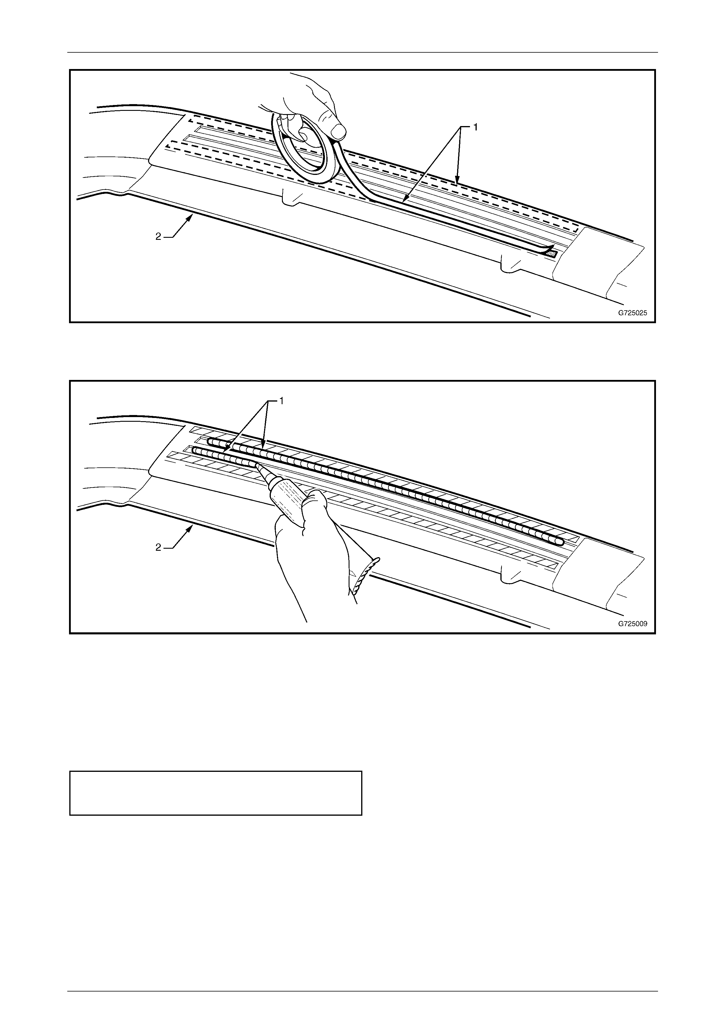
10 Apply double-sided tape (1) (3M or similar with dimensions of 6.0 x 1.0 mm) and a 3mm bead of urethane adhesive
(2) (Wurth Bond + Seal or similar) to the spoiler (3), refer to Figure 12A – 18.
Figure 12A – 18
11 Position the seal (6), four places over each stud in the spoiler, refer to Figure 12A – 16.
12 Align the two centre-mounting studs to the corresponding holes in the rear compartment lid and push the spoiler
gently onto the body.
13 While still holding pressure on the spoiler, reinstall the centre seal (7), spacer (6), nut (5) at two places in the
correct order shown in Figure 12A – 16 and tighten by hand.
14 Reinstall the seal (3), washer (2), screw (1), two places in the order shown in Figure 12A – 16 and hand tighten.
15 Align the spoiler to the body and beginning with the centre nuts, tighten all the screws and nuts evenly to the
specified torque
Lip spoiler nut ........................................... 2.0 – 5.0 N.m
Lip spoiler screw........................................2.0 – 5.0 N.m
15 Refit rear compartment lid carpet if removed, refer to Section 1A4, 3.1 REAR COMPARTMENT LID CARPET in the
MY2003 VY and V2 Series Service Information.
Holden By Design Options Page 12A–20
5-MAR-2003 Page 12A–20
3 HBD Accessories
3.1 Exhaust Extensions
Remove
1 Using a block of wood and a hammer tap the extension from behind until it is clear from muffler.
Reinstall
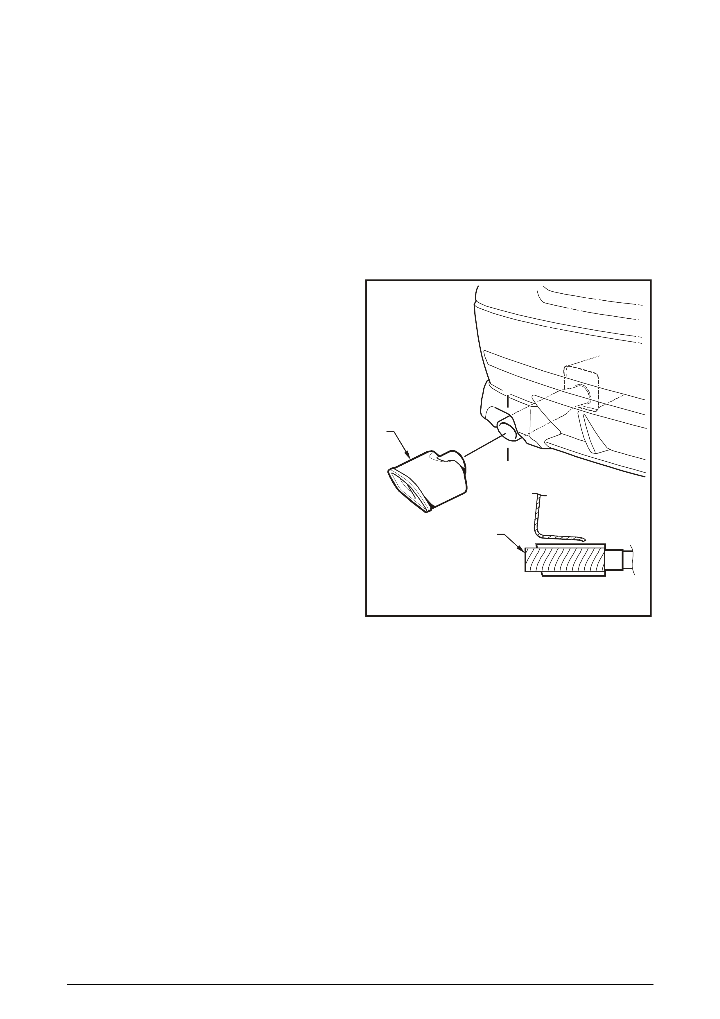
All Levels, Except Performance System
1 For Level one vehicles only, cut 100 mm from the end
of the tail pipe (2) for the installation of the square
style extension (1).
2 Seat and align the exhaust extension squarely to the
vehicle.
3 Using a block of soft wood seated against the
extension and a hammer, gently tap the exhaust
extension onto the rear muffler until it lines up as
required.
G725003
A-A
2
A
1
A
Figure 12A – 19
Holden By Design Options Page 12A–21
5-MAR-2003 Page 12A–21
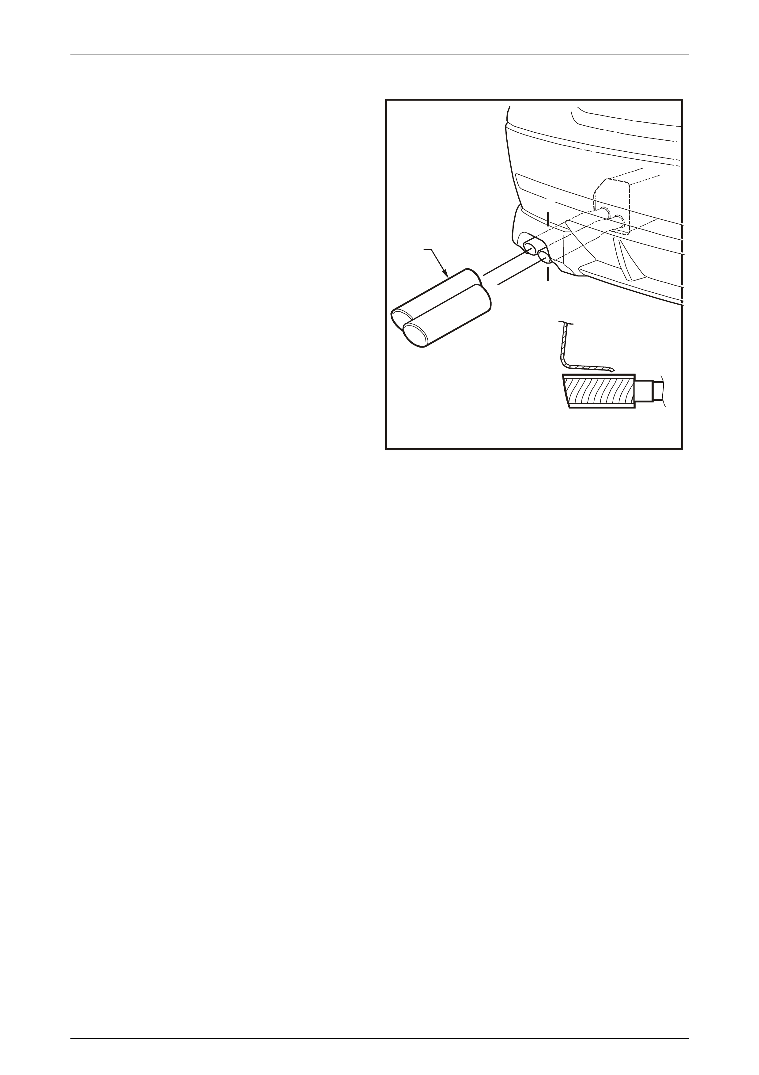
Performance System
1 For performance system vehicles, align the tips (1) in
line with the tail pipes.
2 Using a block of wood and a hammer tap the
extension on until it seats against the end of the tail
pipe.
G725024
A-A
A
A
1
Figure 12A – 20
Holden By Design Options Page 12A–22
5-MAR-2003 Page 12A–22
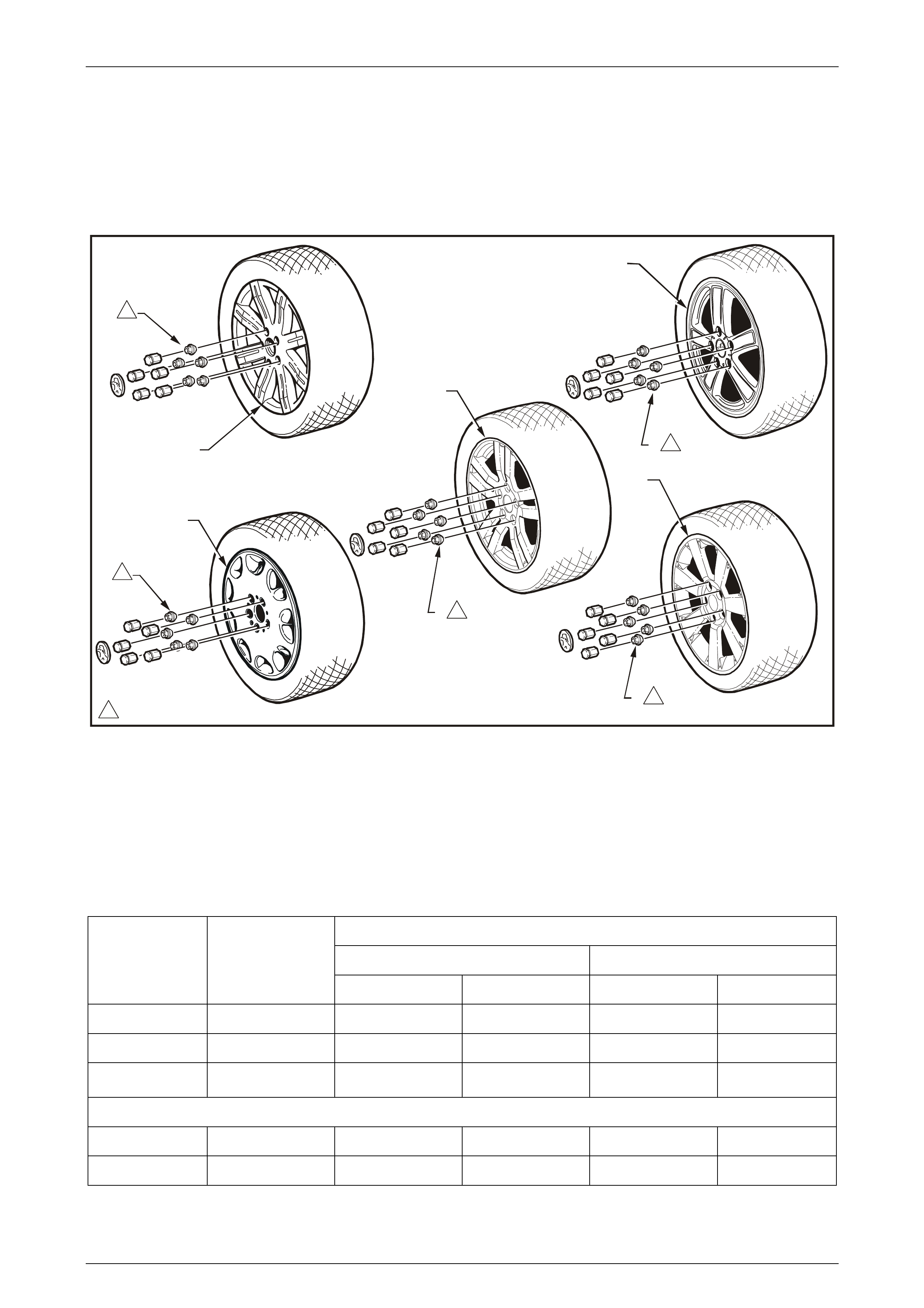
3.2 Wheel Packages
This Section of the Holden By Design Service Information Supplement illustrates and identifies the different tyre and
wheel package options available.
For all tyre and wheel service information, refer to Section 10 WHEELS & TYRES in the MY 2003 VY and V2 Series
Service Information.
1
110 - 140 N.m
6
1
1
G725017
4
2
6
1
3
6
1
6
1
6
1
5
Figure 12A – 21
Legend
1 17" x 8.0 X Series
2 17" x 8.0 H Series
3 17" x 8.0 Y Series
4 16" x 7.50 S Series
5 18" x 8.0 J Series
6 Wheel Nuts
Tyre and Wheel Package Specifications
Recommended Cold Inflation Pressures-kPa (p.s.i.)
Up to 3 passengers UP TO MAX LOAD
Tyre Size
Designation Nominated Rim
Size Front Rear Front Rear
235/45 R17 17x8.00J 220 (32) 220 (32) 270 (39) 270 (39)
235/40 R18 18X8.00J 250 (36) 250 (36) 280 (41) 280 (41)
225/50 R16 7.50J 200 (29) * 200 (29) * 250 (36) * 250 (36) *
For Speeds Above 160 km/h
235/45 R17 17x8.00J 270 (39) 270 (39) 300 (44) 300 (44)
235/40 R18 18X8.00J 290 (42) 290 (42) 340 (50) 340 (50)
* Where shown 50 kPa to be added when vehicle is used for consistent high speeds of above 160km/ h.
Holden By Design Options Page 12A–23
5-MAR-2003 Page 12A–23
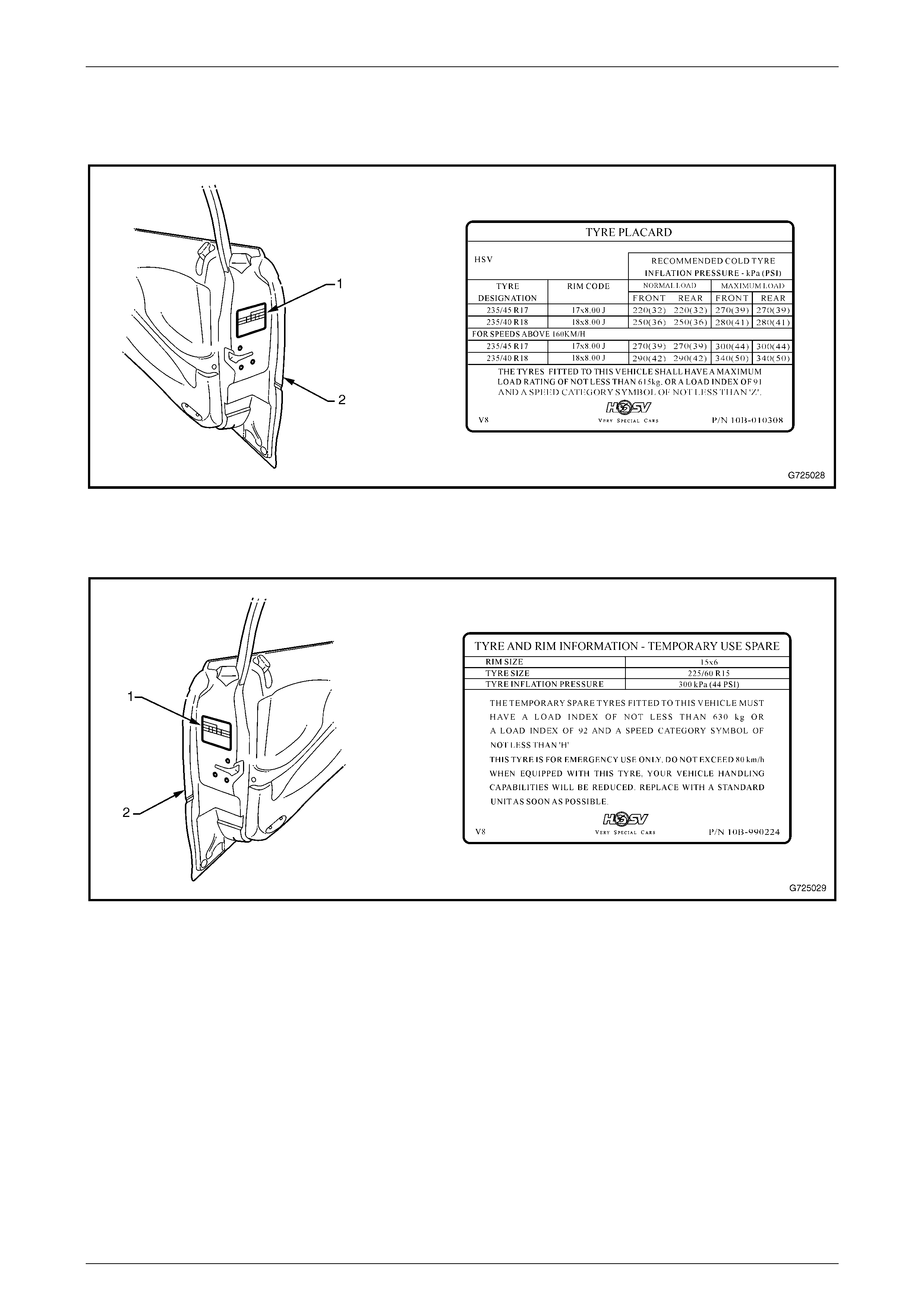
Tyre Placards
Where a Holden By Design tyre and wheel package, the standard tyre placard (1) is replaced with a HBD tyre placard on
the right-hand front door (2). The tyre placard shown in Figure 12A – 22 is typical for all models.
Figure 12A – 22
A temporary spare tyre information placard is also replaced in the same location (1) on the on the left-hand front door (2),
door. The tyre placard shown Figure 12A – 23 is typical for all models.
Figure 12A – 23
Holden By Design Options Page 12A–24
5-MAR-2003 Page 12A–24
3.3 Pedal Pads
Although there are physical differences between the brake and clutch pedal pads, the procedure is the same for both
automatic and manual brake pedals as well as the clutch pedal.
This Section describes the removal and reinstallation of the brake and clutch pedal pads.
Remove
1 Pull the lip (1) of the brake or clutch pedal pad over
the top of the pedal then slide the pad downward to
remove.
Figure 12A – 24
Reinstall
Referring to Figure 12A – 24 reinstall the pedal pad following the steps below.
1 Starting from the bottom the pedal, slide the pad onto the pedal using the cut away (2) as the starting point.
2 Slide the pedal upward until it is in position then, using a small screwdriver gently lever the lip (1) over the top of the
pedal.
Holden By Design Options Page 12A–25
5-MAR-2003 Page 12A–25
3.4 Identification
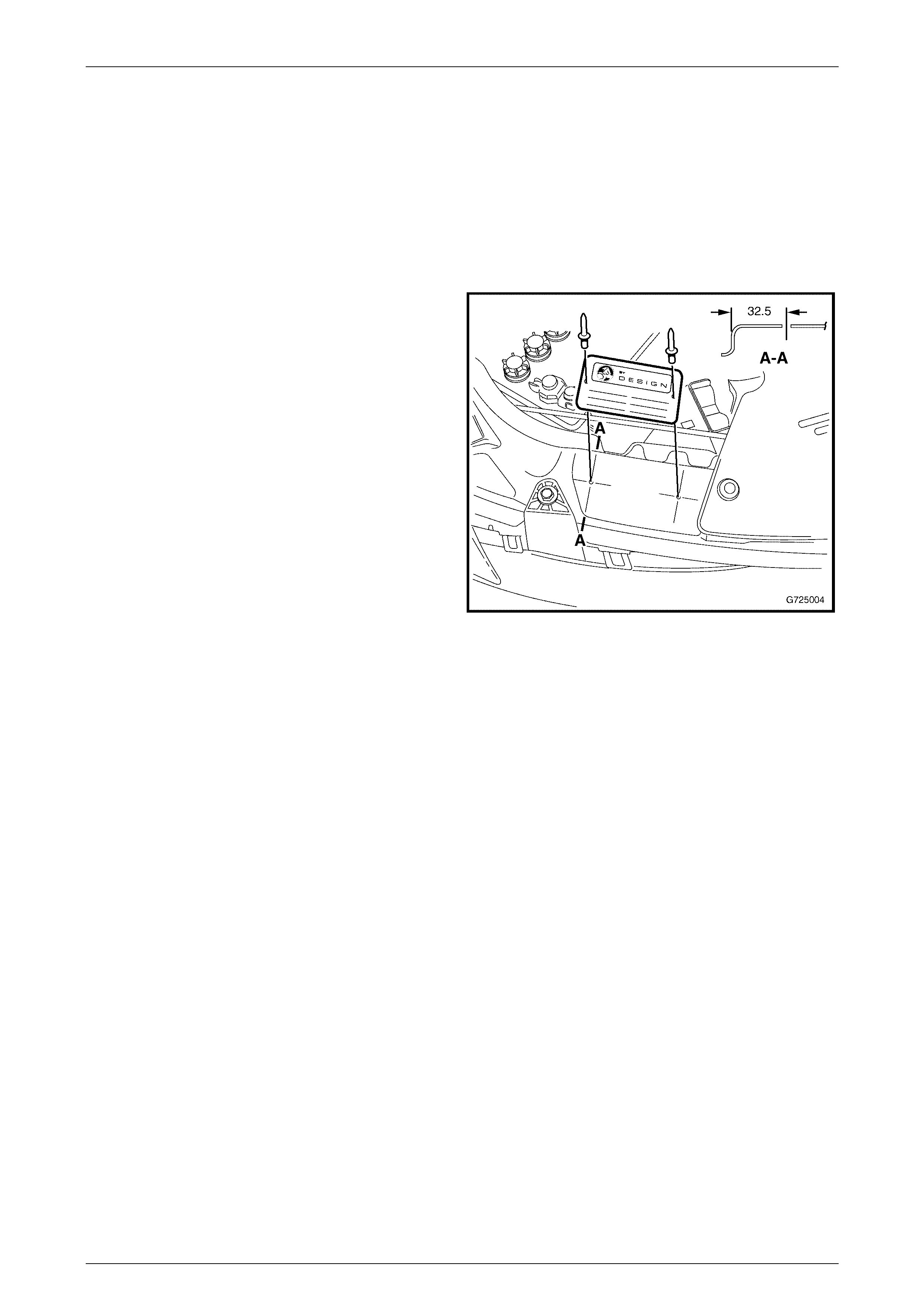
Identification Plate
Remove
1 Drill the rivets attaching the identification plate to the upper front-end panel and remove.
Reinstall
1 Drill two 3mm holes in the upper front-end panel
assembly to the dimensions shown in Figure 12A – 25,
view A – A.
2 Affix the identification plate with pop rivets.
3 If required peel the protective coating from the plate.
Figure 12A – 25
Rear Door Decals
Remove
1 To remove the rear door decals, use a scraper or similar and working from a corner, scrape the decal from the door
glass.
Reinstall
NOTE
Before installing the decal, ensure the glass is
clean and dry before applying the decal.
1 Remove the backing from the decal and apply to the glass using the dimensions for the location. View A is for the
right-hand door and View B is for the left-hand door.
Holden By Design Options Page 12A–26
5-MAR-2003 Page 12A–26
Figure 12A – 26
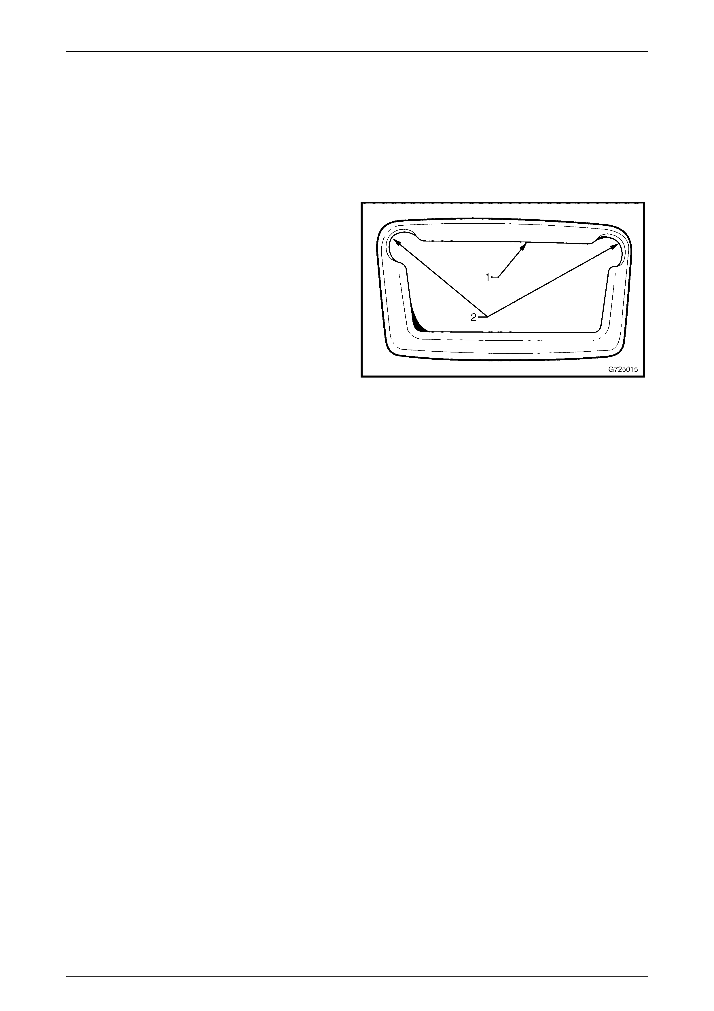
Rear Compartment Lid Emblem
Remove
1 Protect the paint and bodywork with tape or a rag.
2 To assist removal, warm the name plate with a heat-lamp or heat-gun to soften the adhesive.
3 Using a paint scraper or similar, carefully prise the HBD nameplate from the rear compartment lid.
NOTE
Before fitting the badges, remove any remaining
double-sided tape from the badge and/ or body
work and ensure the surface where the badge is
to be located is clean from grease, wax, dirt or
moisture. This can be done, by cleaning the
surface with a wax and grease remover such as
Prepsol or equivalent.
Holden By Design Options Page 12A–27
5-MAR-2003 Page 12A–27
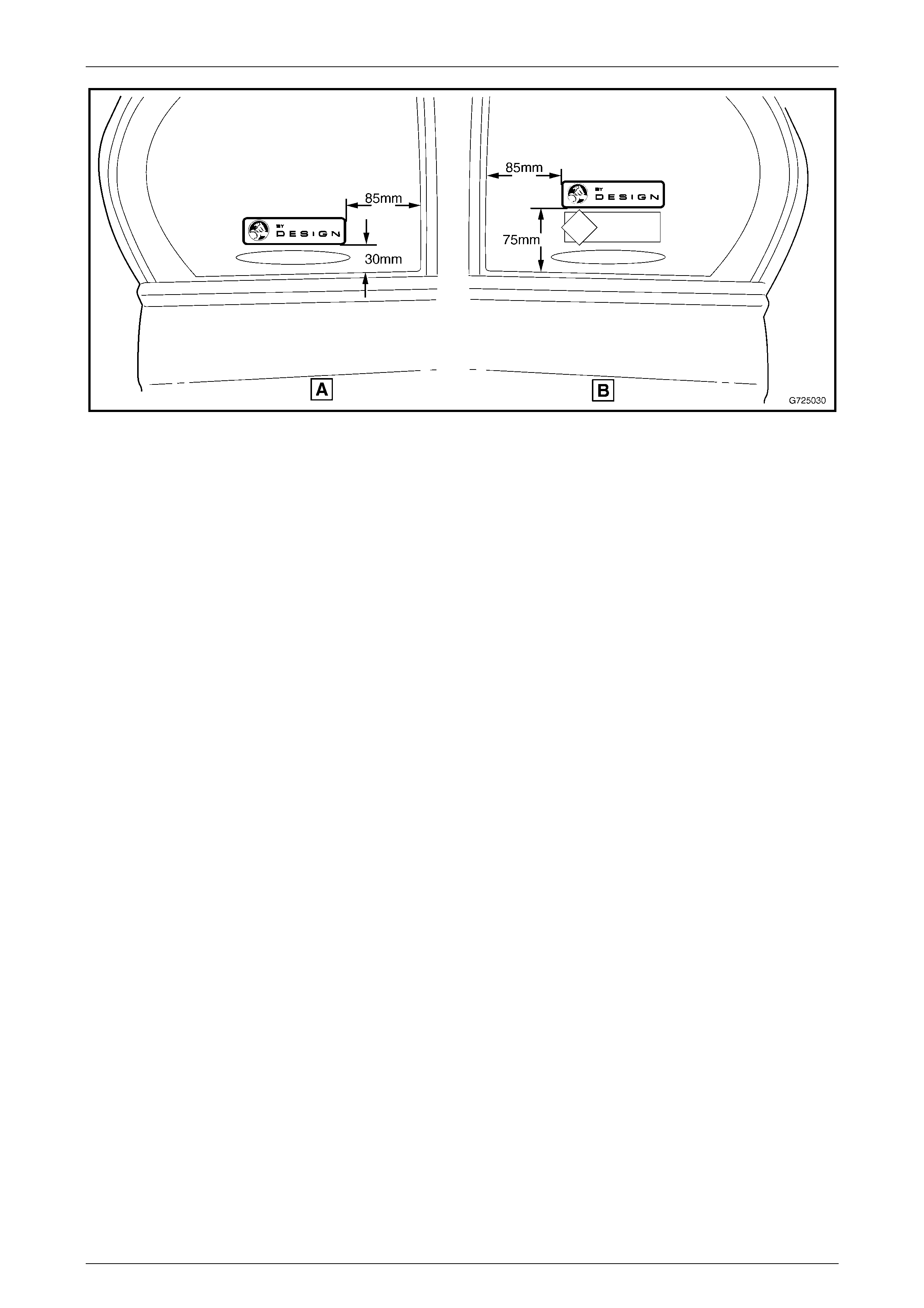
Reinstall
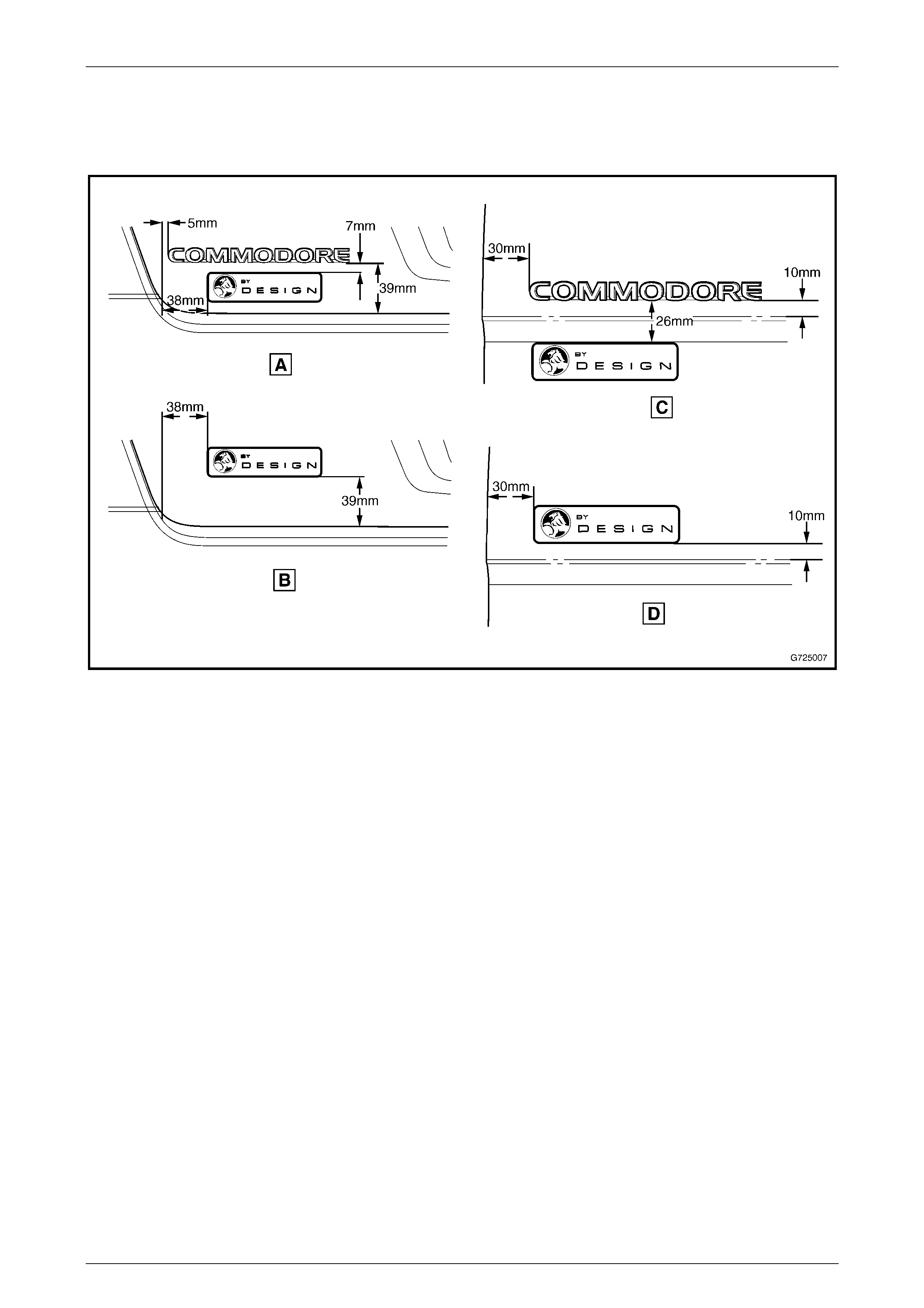
1 Referring to Figure 12A – 27, mark out the correct locations as per the dimension in the appropriate figure.
2 Align the badge in its correct location then fit the badge by pressing the emblem firmly onto the body.
Figure 12A – 27
Legend
A Sedan except Berlina and Calais
B Berlina Sedan and Calais C Wagon except Berlina
D Berlina Wagon

Holden By Design Options Page 12A–28
5-MAR-2003 Page 12A–28
4 Torque Wrench Specifications
Bumper apron end screw..............................................................1.0 – 3.0 N.m
Bumper apron to fascia screw ......................................................1.0 – 3.0 N.m
Lip spoiler screw...........................................................................2.0 – 5.0 N.m
Lip spoiler nut ...............................................................................2.0 – 5.0 N.m