

1. GENERAL DESCRIPTION
This Service Information Supplement describes the service procedures for the body styling kit fitted as standard to
XC Barina SRi vehicles. The body kit consists of the following major components, which are painted the vehicle’s
body colour.
• Front spoiler, attached to the front bumper facia,
• Rocker panel skirts, fitted along each side of the vehicle, and
• Rear spoiler, attached to the liftgate.
The front spoiler and rocker panel skirt are attached to the vehicle with urethane adhesive. In addition, the skirt is
also secured to the vehicle with several retaining clips. The rear spoiler is attached to the liftgate with pressure
sensitive double-sided tape along with four screws.
Replacem ent body kit com ponents ar e supplied in a kit that also inc ludes m ost attaching parts and adhesive, or for
the rear spoiler, double-sided tape. Refer to Figure 1 for the contents of each kit.
A repair kit is also available for the front spoiler, rocker panel sk irt or rear spoiler which provides everything that is
required for reinstalling the component if removal is required without replacing the component.
The front spoiler and rocker panel skirts are made from polyurethane (PUR) while the rear spoiler is made from
sheet moulded compound (SMC). Replacement parts are supplied primed and will require final finishing before
painting. Many different types and brands of paint are available for refinishing the body kit components and while
the painting procedures are relatively straight forward, the correct steps must be followed. Refer to your paint
manufacturer or supplier for further information if required.
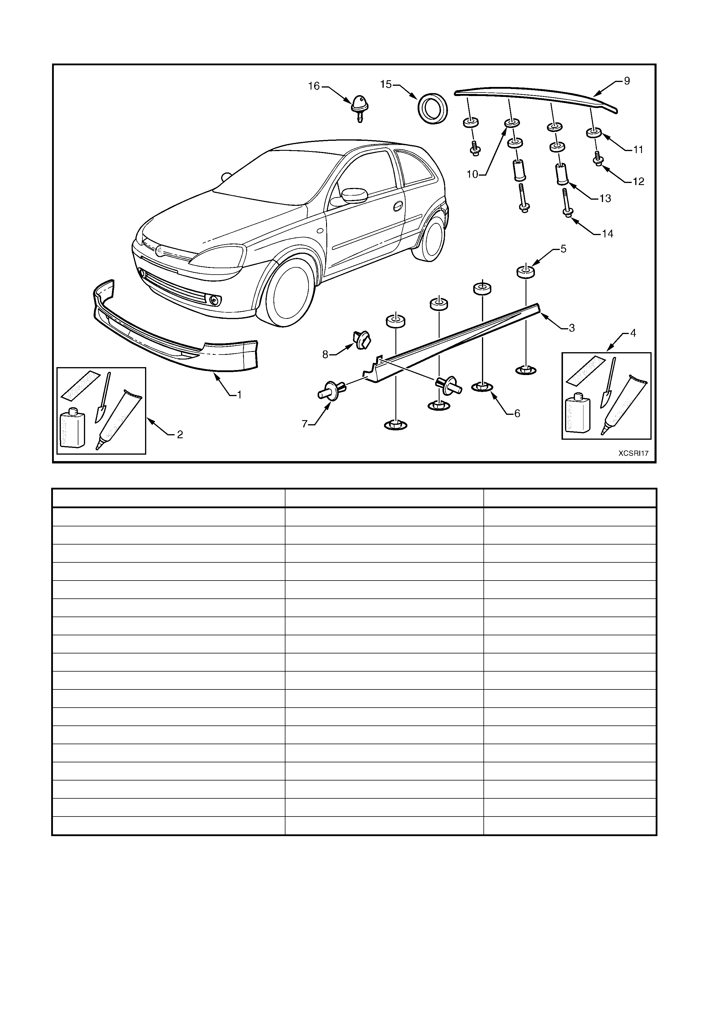
Figure 1
PART INCLUDED IN REPL ACEMENT KI T INCLUDED IN REPAIR KIT
1. Front Spoiler K
2. Front spoiler adhesive kit K K
3. Rocker panel skirt K
4. Rocker panel skirt adhesive kit K K
5. Foam spacer (x 4) K K
6. Retaining clip (x 4) K
7. Retainer (x 2) K K
8. Fender extension retainer (x 4) K K
9. Rear spoiler K
10. Plastic washer (x 2) K K
11. Foam seal (x 4) K K
12. Outer screw (x 2)
13. Spacer (x 2)
14. Inner screw (x 2)
15. Double sided tape K K
16. Rear washer nozzle K K
2. SERVICE OPERATIONS
2.1 FRONT SPOILER
REMOVE
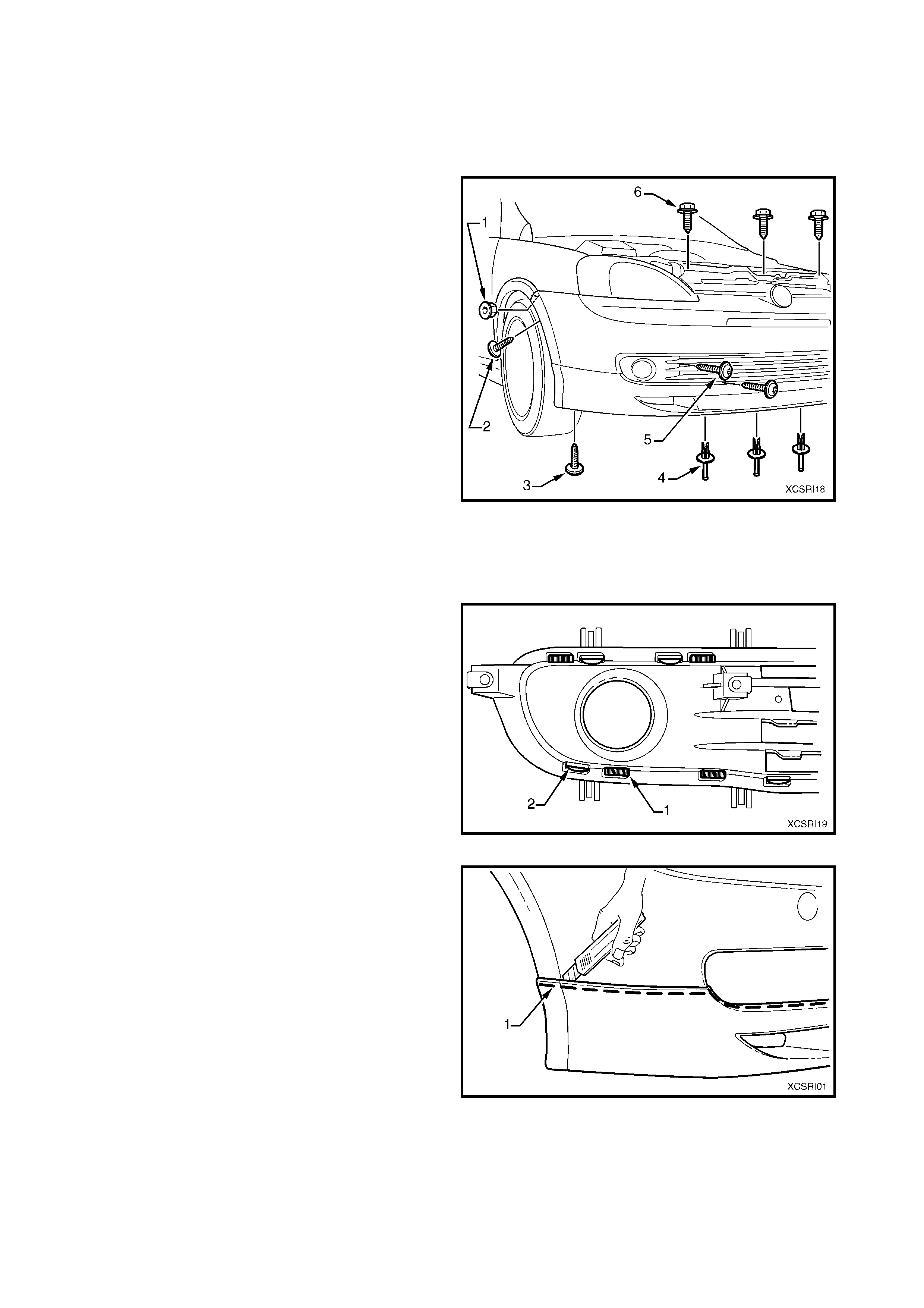
1. Remove the front bumper facia assembly:
A. Remove the nut (1), one place each side of
the vehicle, attaching the front of the fender
extension to the fender.
B. Remove the torx-head screws (2 & 3), one
place each side of the vehicle, attaching the
fender liner to the bumper facia.
C. Remove the retainer (4), three places,
attaching the underside of the bumper facia to
the vehicle, by prising out the centre pin.
D. Remove the torx-head screw (5), two places
each side of the vehicle, attaching the brake
ventilation duct to the bumper facia.
E. Remove the hex -head screw (6), three places,
attaching the bumper facia to the vehicle.
F. With the aid of an assistant, withdraw the
bumper facia from behind each fender
extension and while holding each side of the
facia outwards, withdraw for ward far enough to
disconnect the fog lamp wiring connector near
the left-hand fog lamp.
Figure 2
2. From the rear of the bumper facia, disconnect the
fog lamp wiring connector, remove the three
screws attaching the fog lamp to the lower grille
and remove the lamp. Repeat for the other fog
lamp
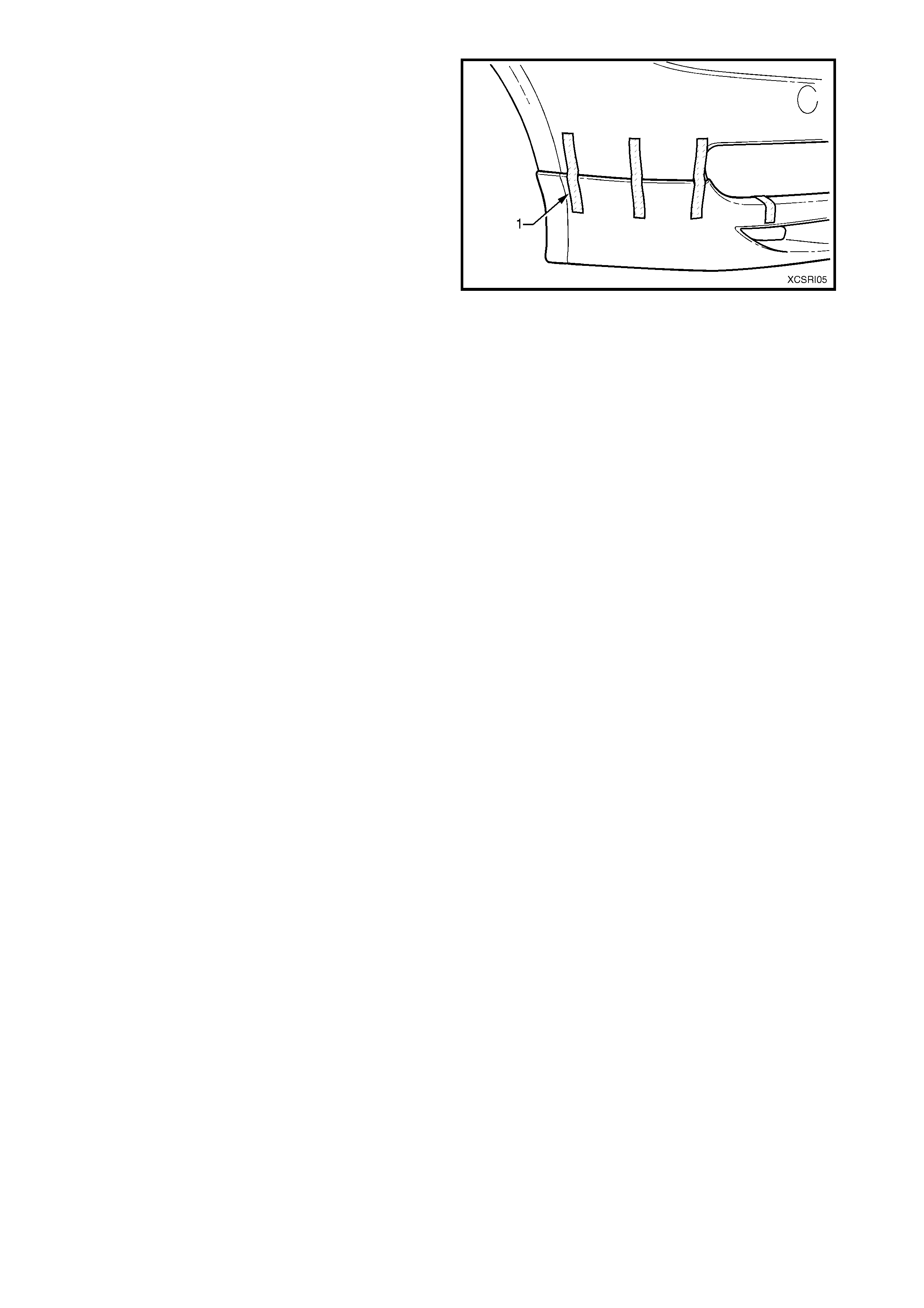
3. Remove the lower grille from the bumper facia by
cutting or grinding the heat stakes (1), four places
each side.
NOTE: Leave as much material as possible to enable
re-heat staking the lower grille on installation.
4. Unclip the lower grille retainers (2), 26 places and
remove the lower grille.
Figure 3
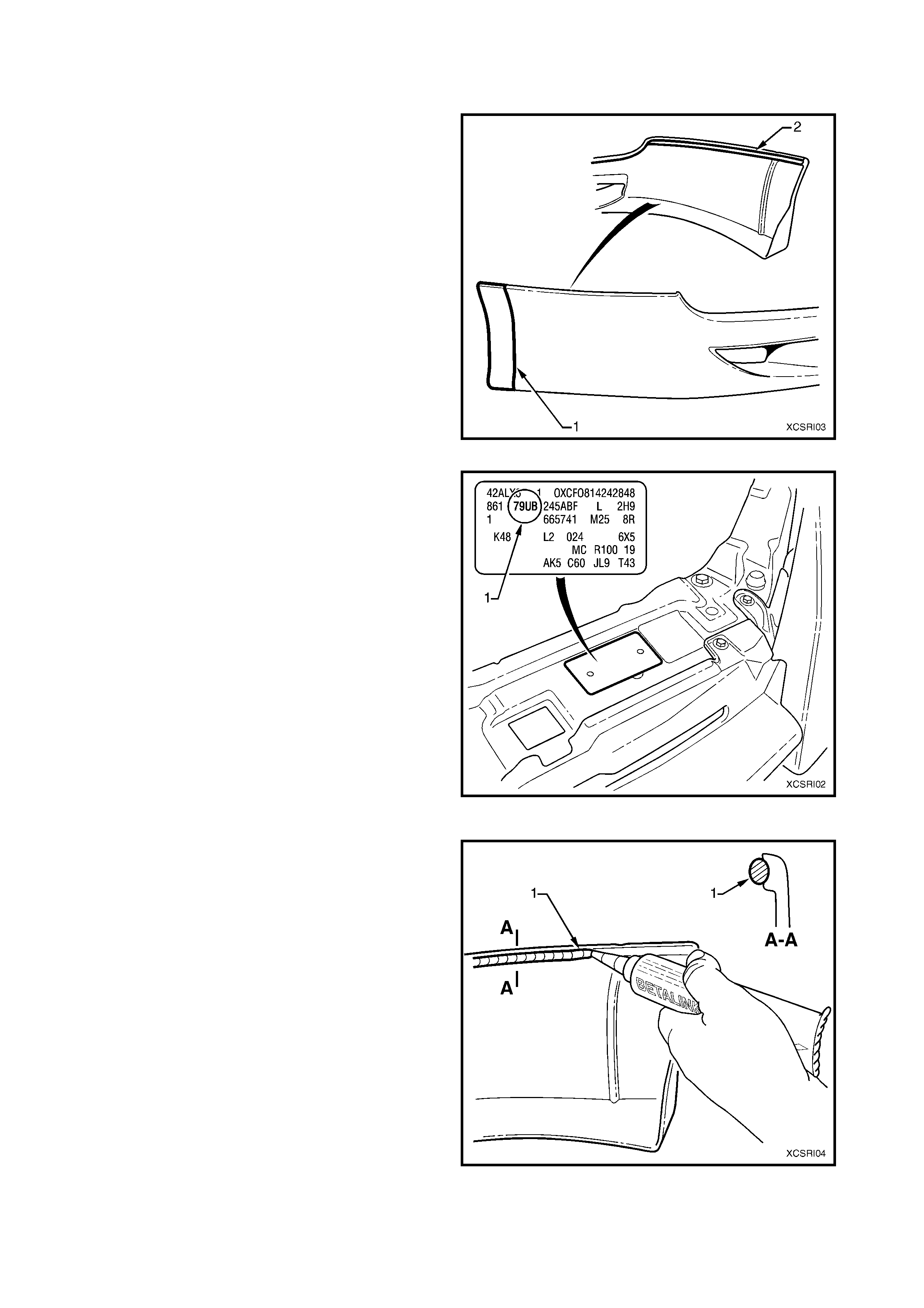
5. Beginning at one end of the spoiler and using a
sharp knife, cut the urethane adhesive bead (1)
between the spoiler and bumper as far as the
lower grille opening.
NOTE: Hold outward pressure on the spoiler to assist
breaking the bead.
6. Repeat for the opposite side.
7. Finally, work through the lower grille opening from
the rear of the bumper facia and cut along the
remaining section of the spoiler.
8. Remove the spoiler.
9. If the spoiler and / or bumper are to be reused,
remove most of the urethane bead with a knife to
provide a smooth, sound surface. It is not
necessary to completely remove it.
Figure 4
REINSTALL
The front spoiler is supplied primed and is to be
painted in the vehicle’s body colour. The rear section
(1) is colour coded to the fender extension.
IMPORTANT: The adhes ive track ( 2) mus t be mask ed
prior to the application of primer or topcoat.
Figure 5
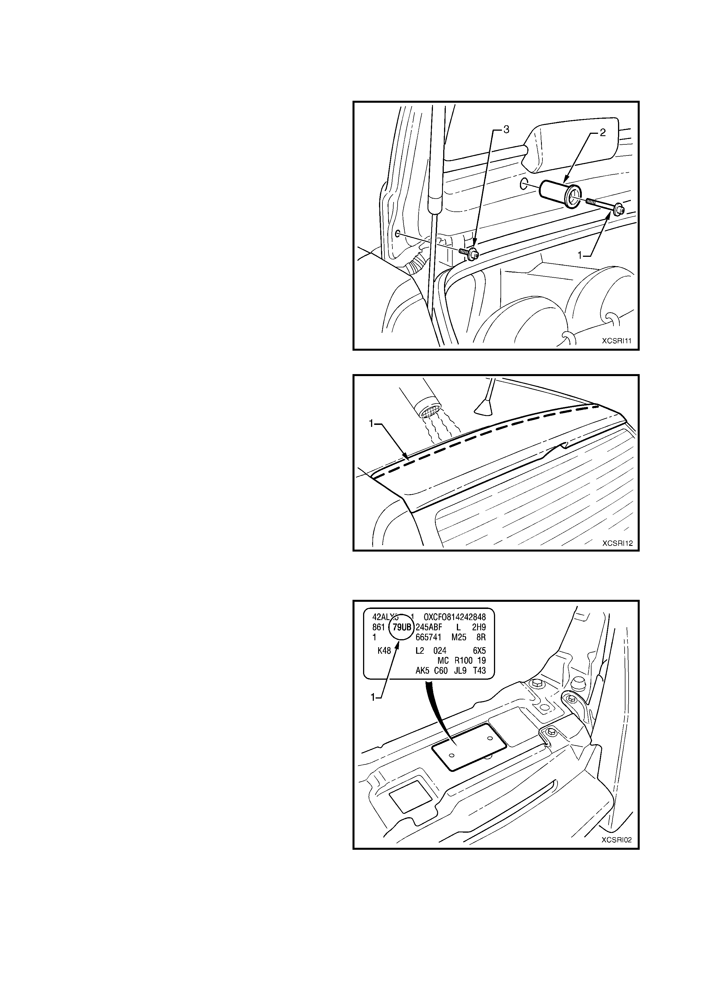
The vehicle paint colour code (1) can be found on the
body option plate, which is attached to the front upper
panel.
While the painting procedures are relatively straight
forward, the correct steps must be followed for
refinishing PUR (polyurethane). Refer to your paint
manufacturer for further information as required.
1. Remove the mas k ing tape from the adhes ive track
on the rear of the spoiler.
2. If required, remove any residual paint from the
adhesive track with 80# sandpaper.
3. Clean the bonding surfaces of the bumper and
spoiler with Prepsol or equivalent and dry
thoroughly with a clean, dry cloth to remove any
residue.
4. Immediately before applying the adhesive, clean
the surf aces with Betaclean 3350 supplied with the
replacement and repair kits, or equivalent.
Figure 6
IMPORTANT: The following steps must be completed
within 15 minutes. Carefully read the directions
provided with the urethane adhesive prior to opening
the package.
5. Using a circular motion, apply a bead of Betalink
K1 urethane adhesive (1) supplied with the
replacem ent and repair kits, or equivalent, into the
track along the upper inside edge of the s poiler as
shown.
Figure 7
6. W ith the aid of an assistant, f it the spoiler caref ully
onto the bumper facia.
7. Press the spoiler onto the bumper and apply
mas k ing tape (1) ac ross the spoiler and bum per to
temporarily fix the spoiler in position.
8. Immediately clean of any excess adhesive as
required using a spatula and the Betaclean 3350
supplied with the replacement and repair kits, or
equivalent.
9. Allow a m inim um of over night curing or as directed
on the instructions provided with the urethane
adhesive.
10. Once cured, remove the tape.
11. Reassemble and install the bumper facia in the
reverse sequence as removal.
NOTE: Fit the lower grille in position on the bumper
facia and ens ure the 26 retainers are sec ured. Using a
soldering iron, melt over the eight heat-stakes to
secure the lower grille in place.
Figure 8
2.2 ROCKER P ANEL SKIRT
REMOVE
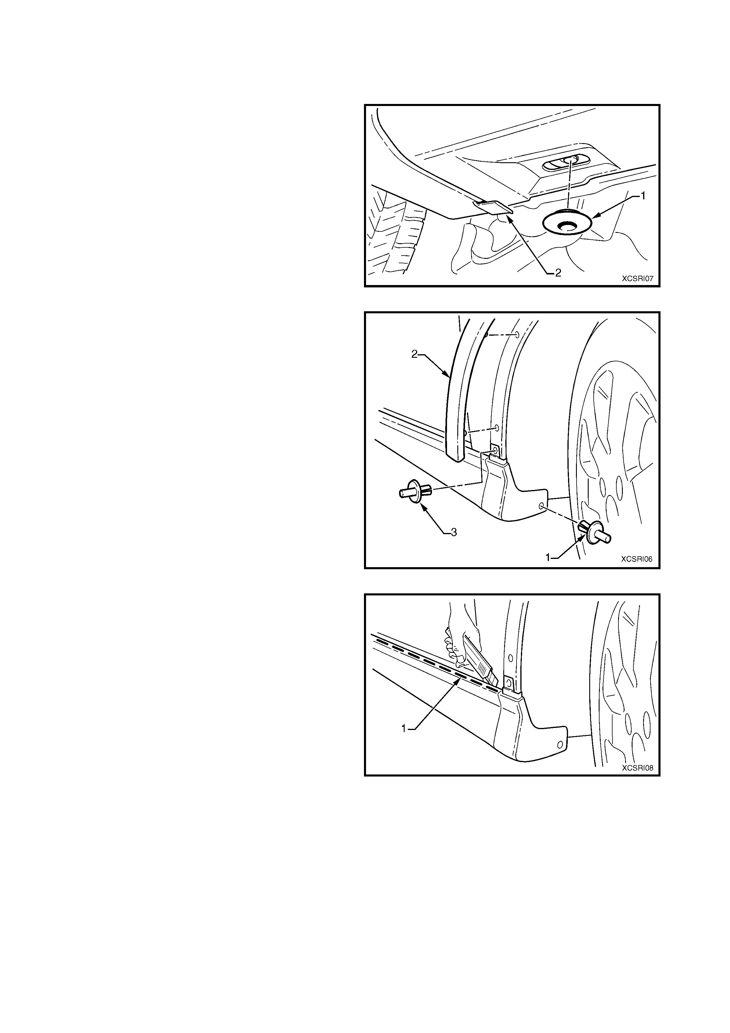
1. Remove the retaining clip (1), four places along
the underside of the rocker panel skirt.
2. Unattach the skirt from the rear wheelhouse
extension tab (2).
Figure 9
3. Remove the retainer (1) attaching the front of the
skirt to the fender liner.
4. Remove the rear section of the front fender
extension (2).
NOTE: To avoid breaking the retaining clips, remove
the rear sec tion of the f ender liner and depress the clip
tangs from the inner side of the fender. New clips are
supplied with a new skirt or in the rocker panel skirt
repair kit.
5. Remove the retainer (3) attaching the front of the
skirt to the fender.
Figure 10
6. Begin at the front retainer hole and using a sharp
knif e, cut the urethane adhesive bead ( 1) between
the skirt and body.
NOTE: Hold outward pressure on the skirt to assist
breaking the bead.
7. Continue cutting along the entire length and down
the rear edge of the skirt.
8. Remove the skirt from the vehicle.
Figure 11
9. If required, remove the four foam spacers at each
of the retaining clip attaching posts on the
underside of the rocker panel.
10. If the skirt is to be reused, remove most of the
urethane bead with a knife to provide a smooth,
sound surface. It is not necessary to completely
remove it.
Figure 12
REINSTALL
The rocker panel skirt is supplied primed and is to be
painted in the vehicle’s body colour. The front section
(1) is colour coded to the wheel arch extension.
IMPORTANT: The adhes ive track ( 2) mus t be mask ed
prior to the application of primer or topcoat.
Figure 13
The vehicle paint colour code (1) can be found on the
body option plate, which is attached to the front upper
panel.
While the painting procedures are relatively straight
forward, the correct steps must be followed for
refinishing PUR (polyurethane). Refer to your paint
manufacturer for further information as required.
1. Rem ove the m ask ing tape f rom the adhesive tr ack
on the rear of the skirt.
2. If required, remove any residual paint from the
adhesive track with 80# sandpaper.
3. Clean the bonding surfaces of the rocker panel
and skirt with Prepsol or equivalent and dry
thoroughly with a clean, dry cloth to remove any
residue.
4. Immediately before applying the adhesive, clean
the surf aces with the Betaclean 3350 supplied with
the replacement and repair kits, or equivalent.
Figure 14
IMPORTANT: The following steps must be completed
within 15 minutes. Carefully read the directions
provided with the urethane adhesive prior to opening
the package.
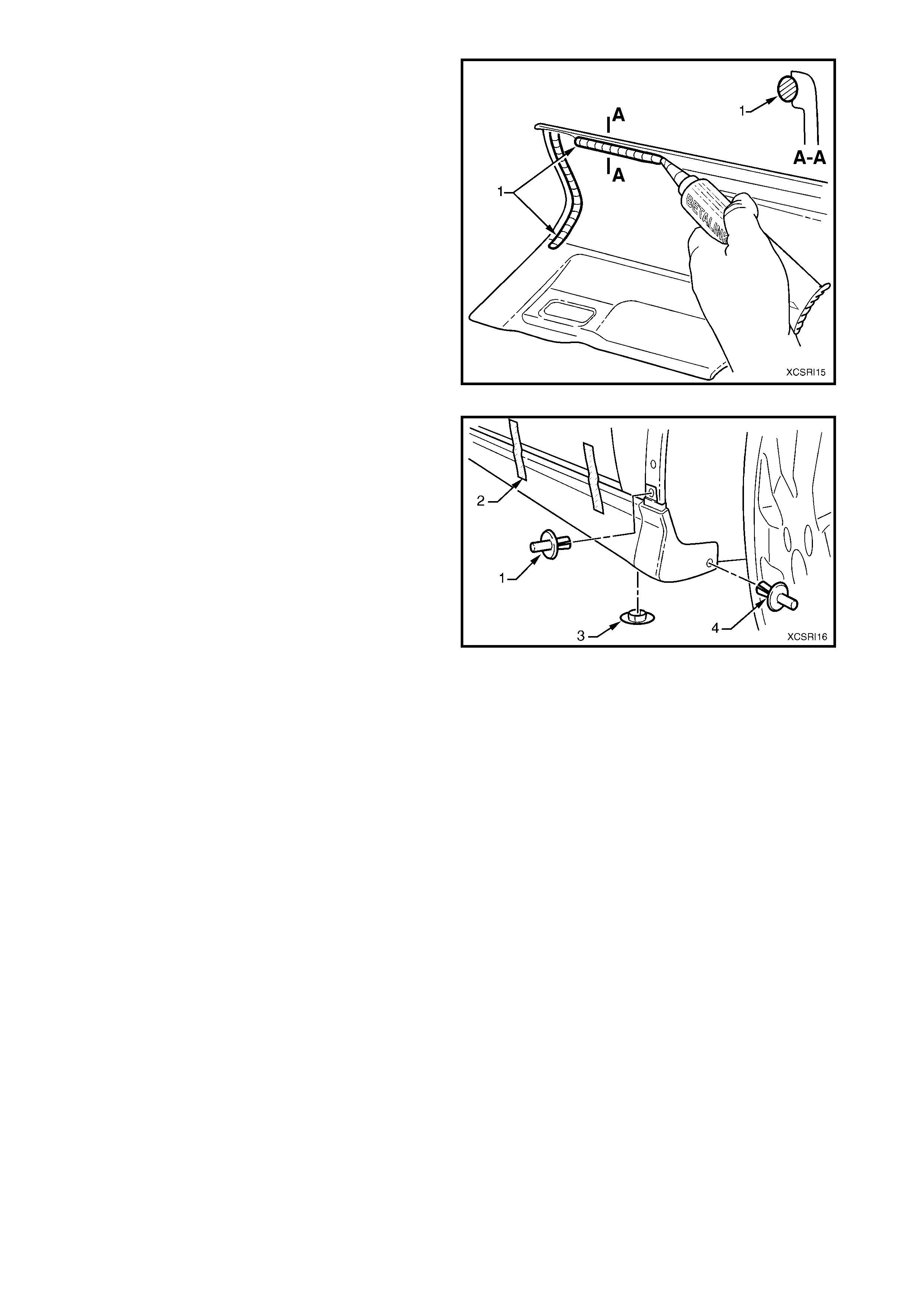
5. Using a circular motion, apply a bead of Betalink
K1 urethane adhesive (1) supplied with the
replacement and repair kits, or equivalent, along
the rear edge of the skirt and into the track along
the upper inside edge of the skirt as shown.
Figure 15
6. With the aid of an assistant, fit the skirt carefully
onto the vehicle, sliding the rear of the skirt under
the rear wheelhouse extension retaining lug, refer
(2) in Figure 9.
7. Fit the retainer (1) at the front of the skirt.
8. Press the upper edge of the skirt onto the rocker
panel and apply masking tape (2) across the skirt
to temporarily fix it in position.
9. Fit the retainer (3), four places to the underside of
the skirt.
10. Fit the retainer (4) at the front of the skirt into the
fender liner.
NOTE: If the fender liner has been replaced, drill a 6
mm hole.
11. Recheck the top edge of the skirt to ensure it is
seated correctly along the sill panel, adjust as
required.
12. Clean of any excess adhesive as required using a
spatula and Betaclean 3350 supplied with the
replacement and repair kits, or equivalent.
13. Allow a minim um of overnight curing or as directed
on the instructions provided with the urethane
adhesive.
12. Once cured, remove the tape.
13. Reinstall the fender liner.
Figure 16
2.3 REAR SPOILER
REMOVE
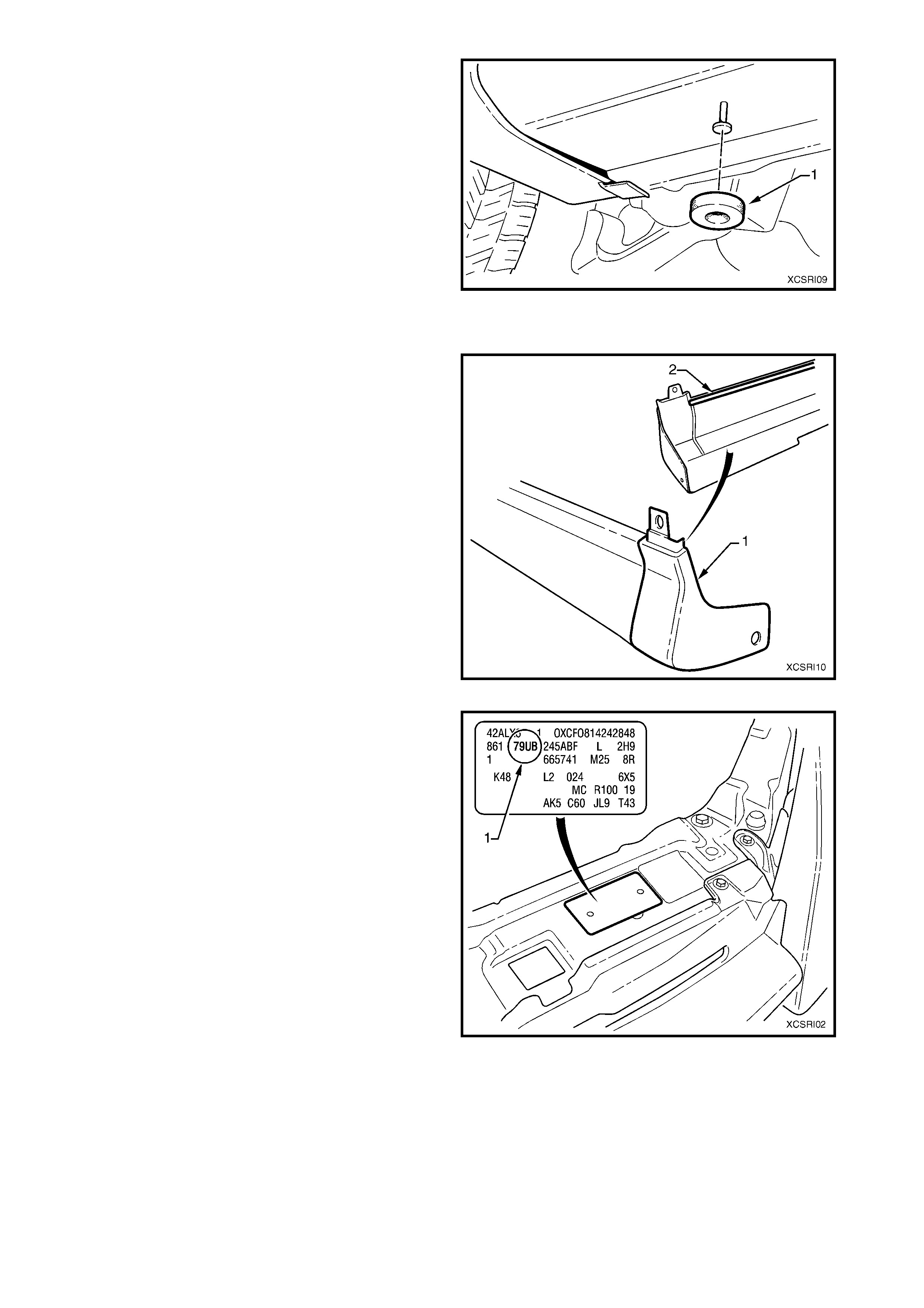
1. Remove the screw (1) and spacer (2), one place
each side, attaching the rear spoiler to the liftgate.
2. Remove the screw (3), one place each side,
attaching the rear spoiler to the liftgate.
Figure 1
3. Begin at one end of the spoiler and while holding
upward pressure, carefully prise the front edge of
the spoiler from the liftgate, breaking the double-
sided tape (1) bond.
NOTE: Use of a heat gun will soften the adhesive,
aiding removal.
4. If the spoiler is to be reused, remove the double-
sided tape and clean off any remaining adhesive.
Figure 18
REINSTALL
The rear spoiler is supplied primed and is to be painted
in the vehicle’s body colour.
The vehicle paint colour code (1) can be found on the
Body Option plate, which is attached to the front upper
panel.
While the painting procedures are relatively straight
forward, the correct steps must be followed for
refinishing SMC-UP (Sheet Moulded Compound).
Refer to your paint manuf ac tur er f or f ur ther information
as required.
1. Clean the bonding surfaces of the liftgate and
spoiler with Prepsol or equivalent and dry
thoroughly with a clean, dry cloth to remove and
residue.
Figure 19
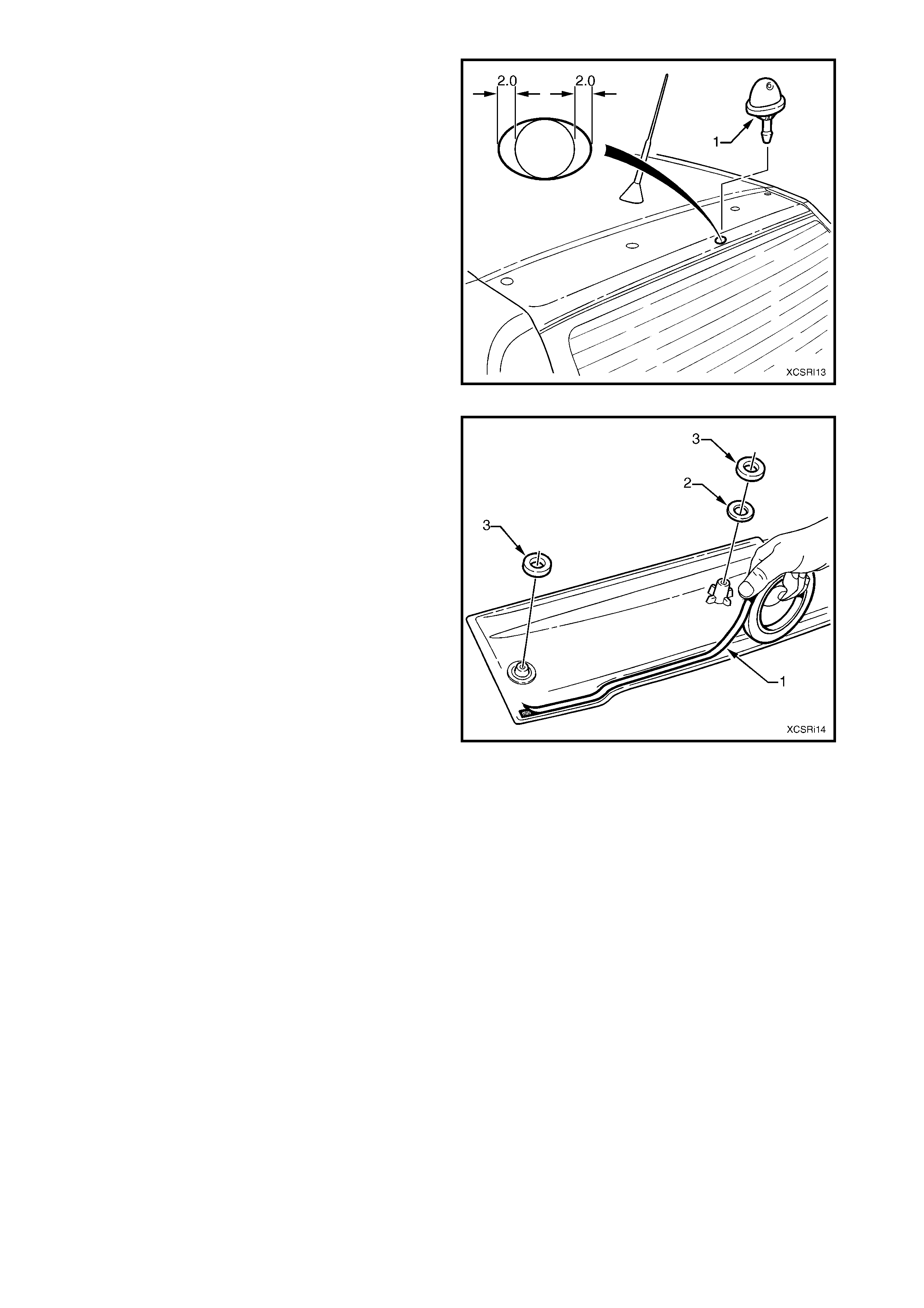
2. If a new liftgate has been fitted, carefully enlarge
the washer nozzle hole two millimetres each side
to accept the new nozzle for the spoiler.
3. Remove any swarf and prime and paint the bare
metal.
4. Install the nozzle (1) supplied with the replacement
spoiler.
5. Clean the bonding surfaces of the liftgate and
spoiler with Prepsol or equivalent and dry
thoroughly with a clean, dry cloth to remove any
residue.
Figure 20
6. Apply a length of the 3M Pressure Sensitive Tape
(1) supplied with the replacement and repair kits,
or equivalent, along the forward edge of the
spoiler.
7. Fit a plastic washer ( 2) to the inner mounting bos s
each side.
8. Rem ove the back ing paper and af fix the foam s eal
(3) to the inner and outer mounting boss, two
places each side.
9. Remove the backing paper from the double-sided
tape and with the aid of an assistant, fit the spoiler
carefully onto the liftgate, ensuring the mounting
bosses align in their respective holes in the liftgate.
10. Press the spoiler firmly into position to ensure a
positive bond of the double-sided tape.
11. Install the outer screws and the inner spacers and
screws from the inside of the liftgate.
12. Tighten the screws securely.
13. Check the water spray from the liftgate washer
nozzle. If required, adj ust by inserting a pin into the
nozzle jet and set it to the desired position.
Figure 21