SECTION B – BODY
IMPORTANT
Before performing any Service Operation or other procedure described in this Section, refer to Section 00
CAUTIONS AND NOTES for correct workshop practices with regard to safety and/or property damage.
PURPOSE
The purpos e of this sect ion is to prov ide inform ation on the bod y and body com ponents fitted to H SV GTO & G TS
Coupe vehicles. The information is designed to supplement the information contained in the Holden V2 Coupe
series Service Manuals, and details are given where differences occur between the HSV models and standard
Holden models. A series of instruction drawings describe the design changes and indicate specific part numbers,
fitting instructions and relevant notes for vehicle servicing.
NOTE:
If specific technical data on a HSV model is not contained in this supplement, obtain data for that model from the
relevant Holden V2 Coupe series Service Manual Supplement. References are made throughout this section to
Holden Service Manuals, to assist in providing information for specific service operations.
CAUTION:
W hen hoisting (or jac king) HSV models , ensure that the lifting h ead of the hoist l ifts on the chass is before the ar m
of the hoist contacts the side-skirt

1. GENERAL INFORMAT ION
The HSV GTO and GTS Series Coupe is a two-door variant of the HSV VX Series II Clubsport Model. The HSV
GTO and GTS Series Coupe retains the same track and wheelbase as the HSV VX Series II Clubsport and the
major exterior body sheet metal panels carry over from the Holden V2 Series Models. HSV GT O and GTS m odels
are equipped with unique Body Side Sk irts, 3-piece Rear Spoiler, Roof Spoiler, Front Bum per Bar Facia and Rear
Bumper Bar Facia.
For all body alignment dimensions refer to Section 1A2 – BODY DIMENSIONS of the Holden V2 Coupe Series
Models Service Information.
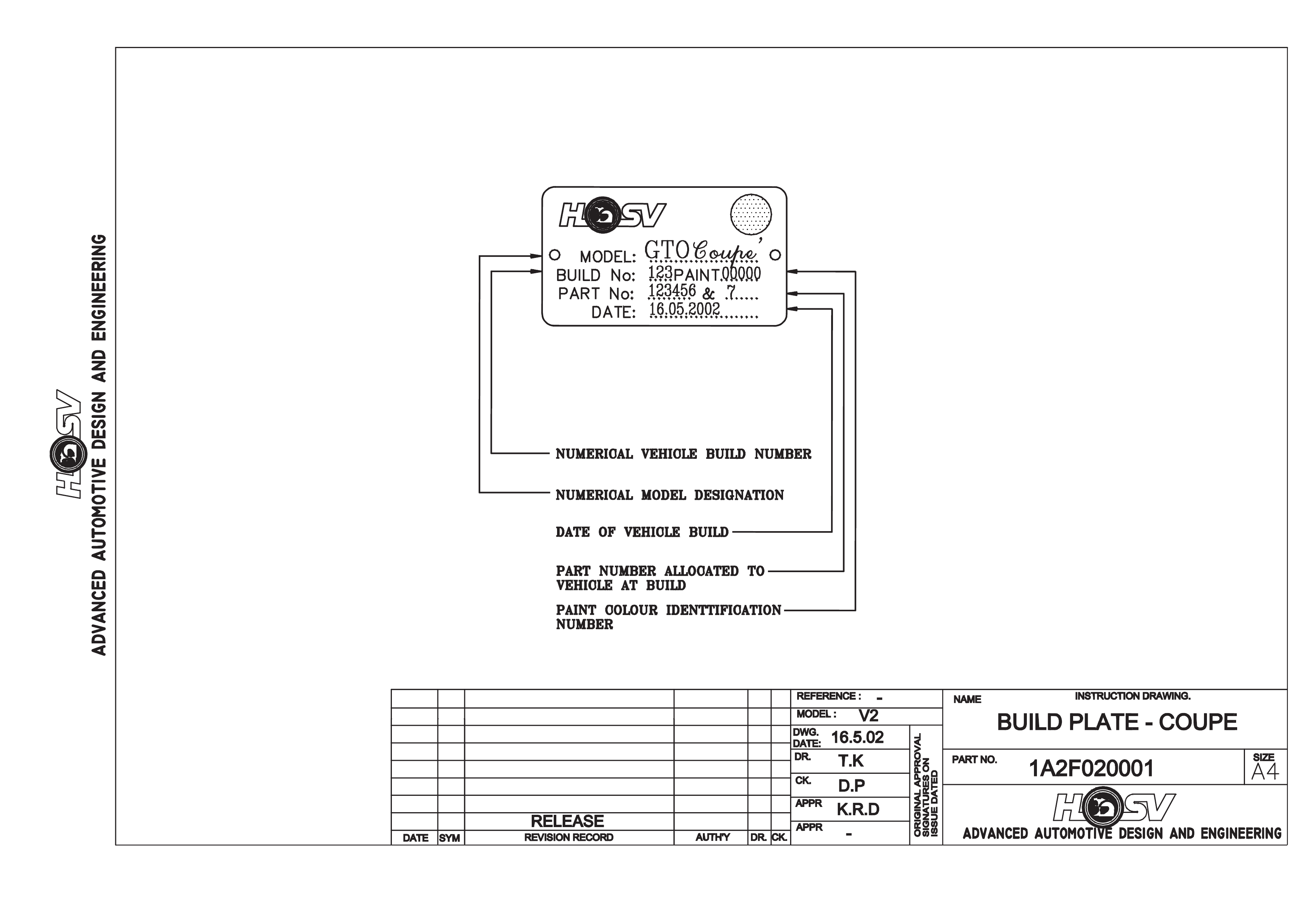
HSV BUILD PLATE
HSV vehicles can be identified by the HSV Vehicle Build Plate, which is mounted in the engine compartment. An
example of an HSV Build Plate is shown in Drawing 1A2F020001. For the HSV Coupe models it is a black over
gold finish.

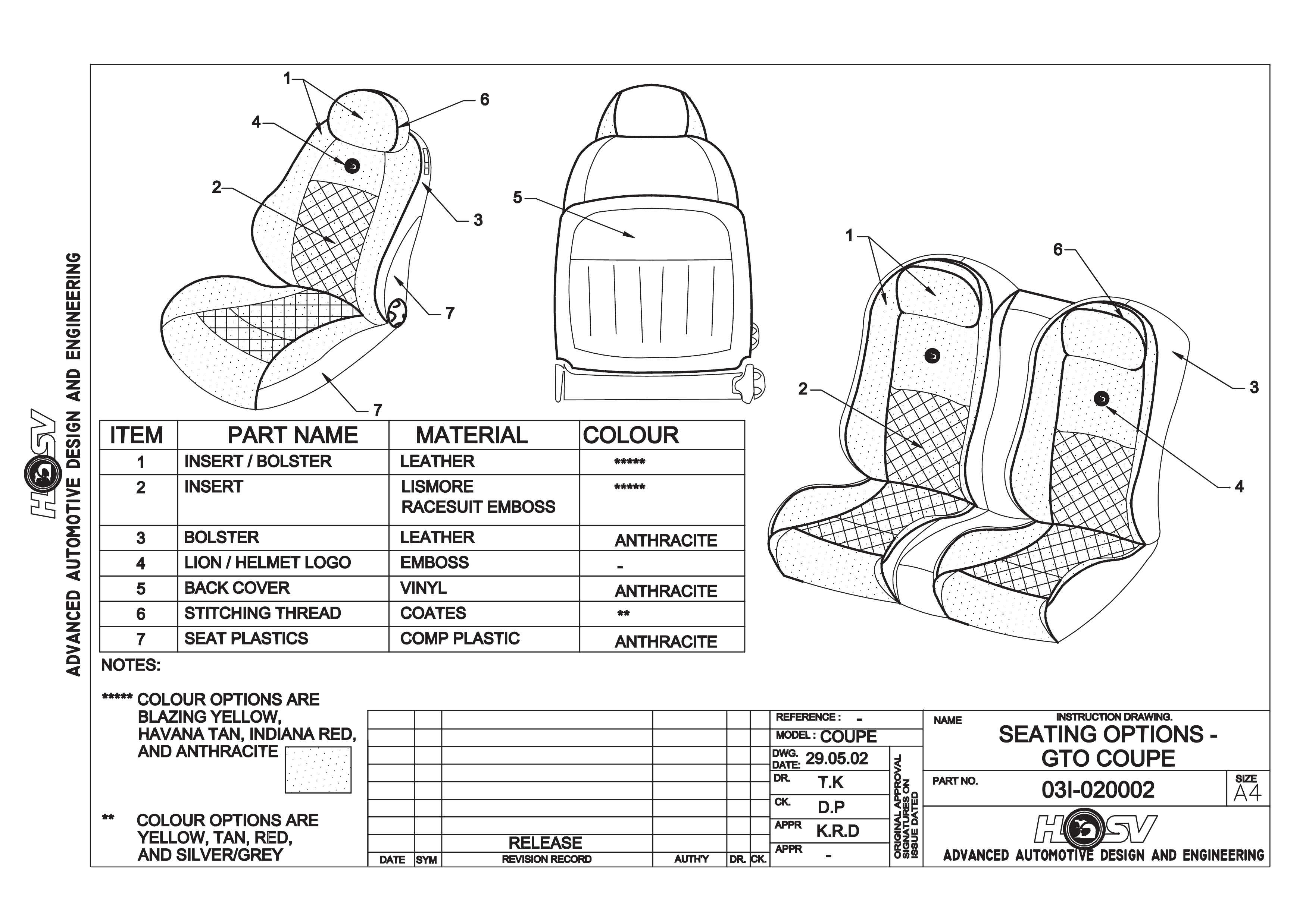
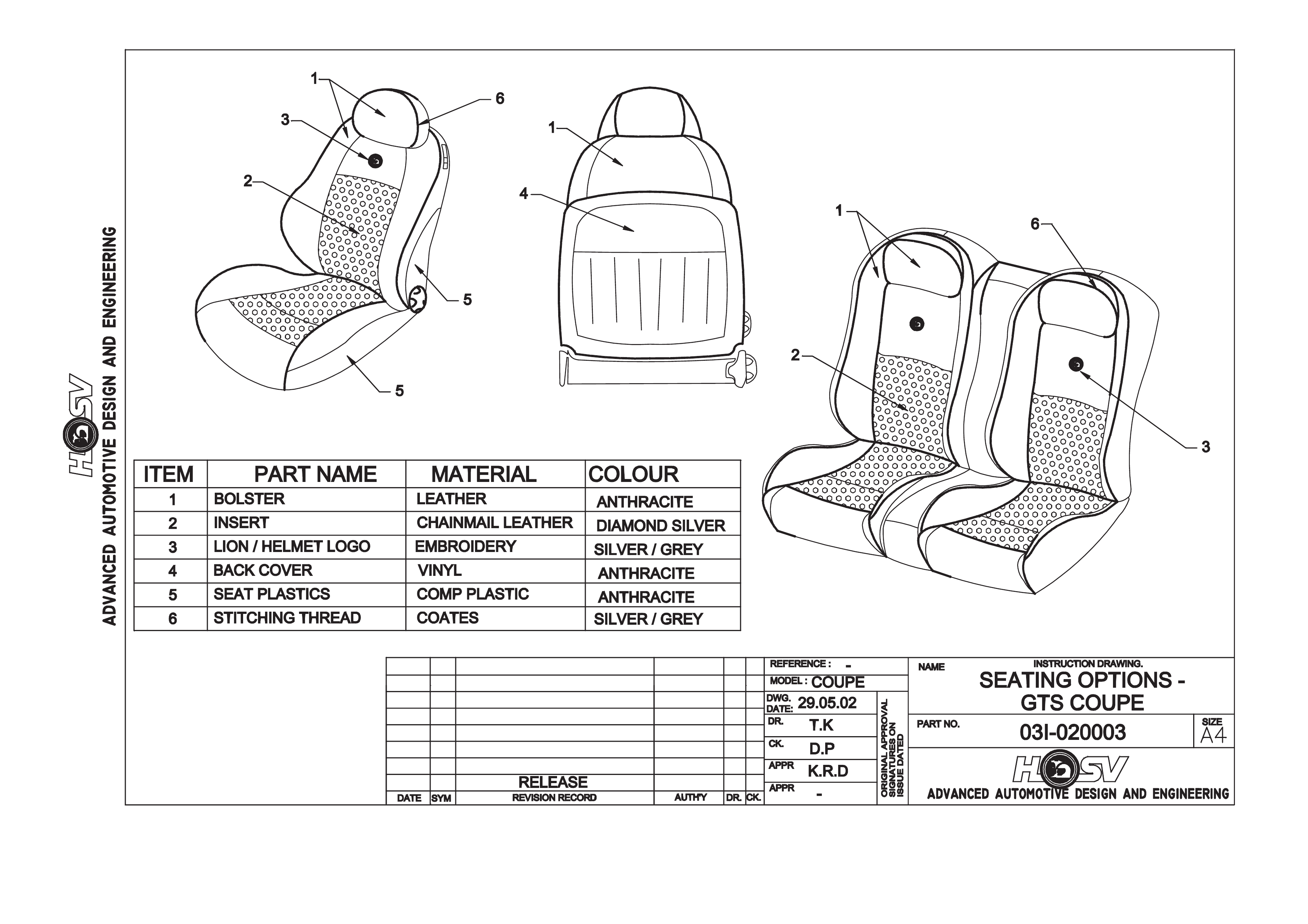
SEATS
HSV GTO & GTS Coupe models are fitted with exclusive seat designs to compliment the Sport or Performance ride
pack ages of eac h veh icl e. The GT O and GTS seats ( shown f or id ent if ic ati on p ur p oses in Dr a win gs 03I-020002 and
03I-020003) have specific seats covered in model-specific trim material ranging from Jacquard and Velour cloth
through to full leather. A full range of replacement parts is available for each specific HSV seat item.

BODY ORNAMENT ATION
HSV models are fitted with HSV specific decals, and badges to identify each model and power train option. The
exclusive HSV ornamentation is positioned in exact locations on each HSV model. The ornamentation for each
model is specified by part number in this section. Accurate dimensions are also provided to assist with the
replacement of these parts.

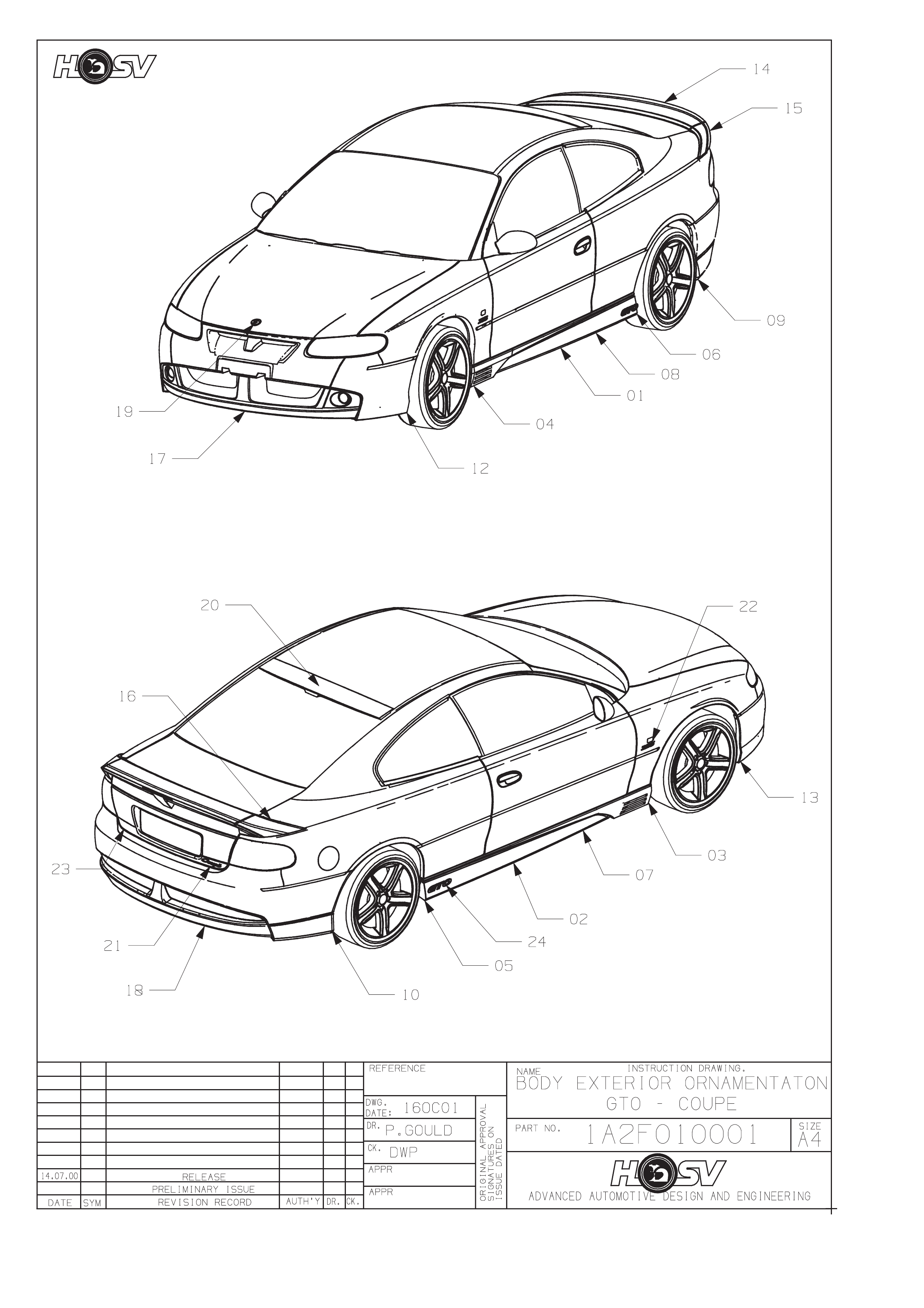
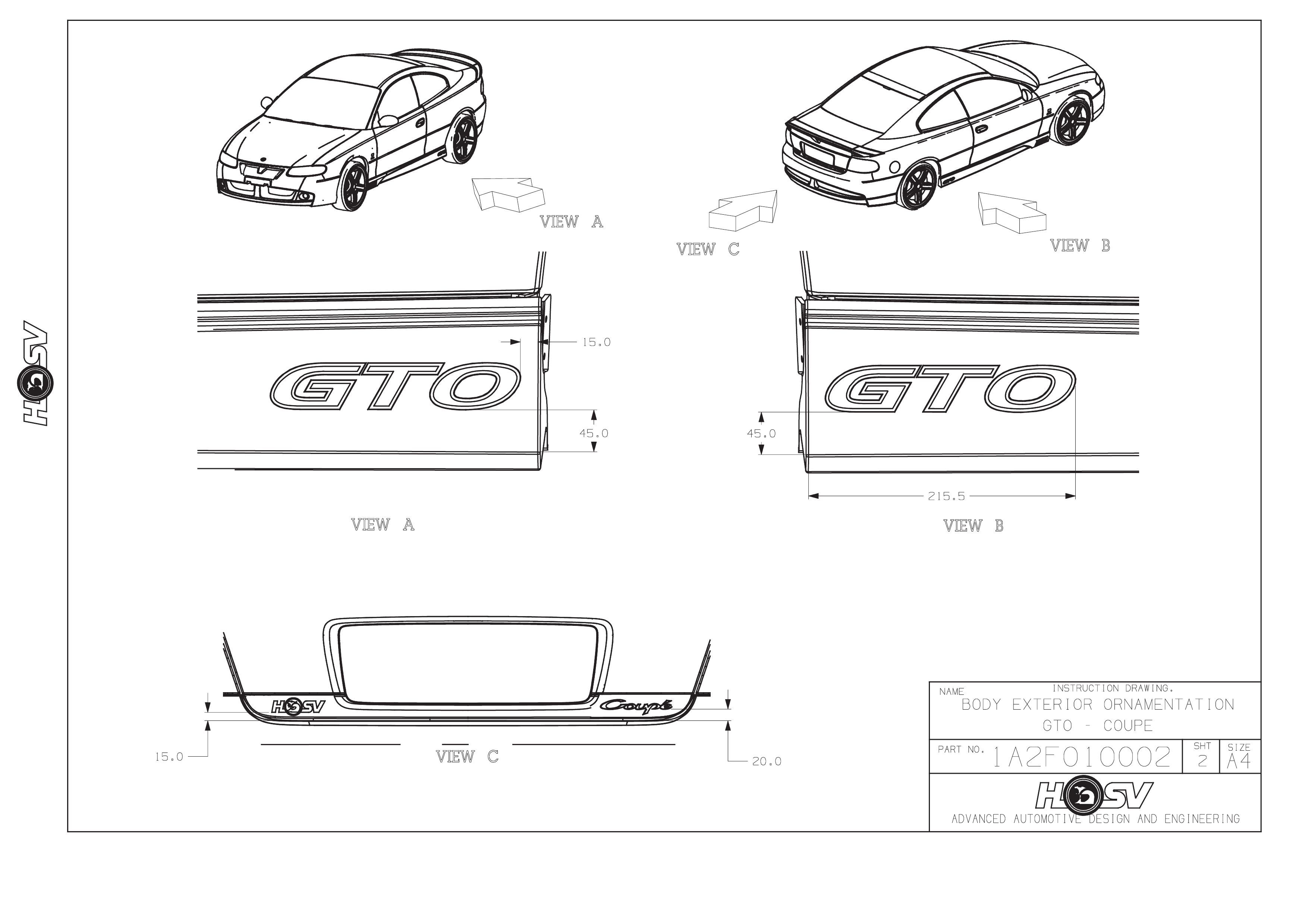
GTO COUPE
CONTENTS OF BODY STYLING PACKAGE
REFER TO DRAWING 1A2F-010001
PART No QTY DESCRIPTIONS FIGURE REF
A08-021101 1 SKIRT - ROCKER-LH* 1
A08-021102 1 SKIRT - ROCKER-RH* 2
A08-021104 1 PAINT PROTECTOR-S/SKIRT FRT RH 3
A08-021103 1 PAINT PROTECTOR-S/SKIRT-FRT LH 4
A08-021106 1 PAINT PROTECTOR-S/SKIRT-RR RH 5
A08-021105 1 PAINT PROTECTOR-S/SKIRT-RR LH 6
A08-021110 1 PAINT PROTECTOR S/SKIRT-SIDE-RH 7
A08-021109 1 PAINT PROTECTOR S/SKIRT-SIDE-LH 8
A08-970607 2 BADGE-HSV CORPORATE LOGO 9
B08-970301 1 BADGE-LION & HELMET (BONNET) 19
H08-021101 1 SPOILER - REAR DECKLID - CENTRE 14
E08-021106 1 BADGE – GTO 24
12C-000601 1 LAMP FOG LH
14A-1000603 2 SPACER FOG LAMP
12E-021101 1 LAMP ASM-HI MOUNT STOP LIGHT 25
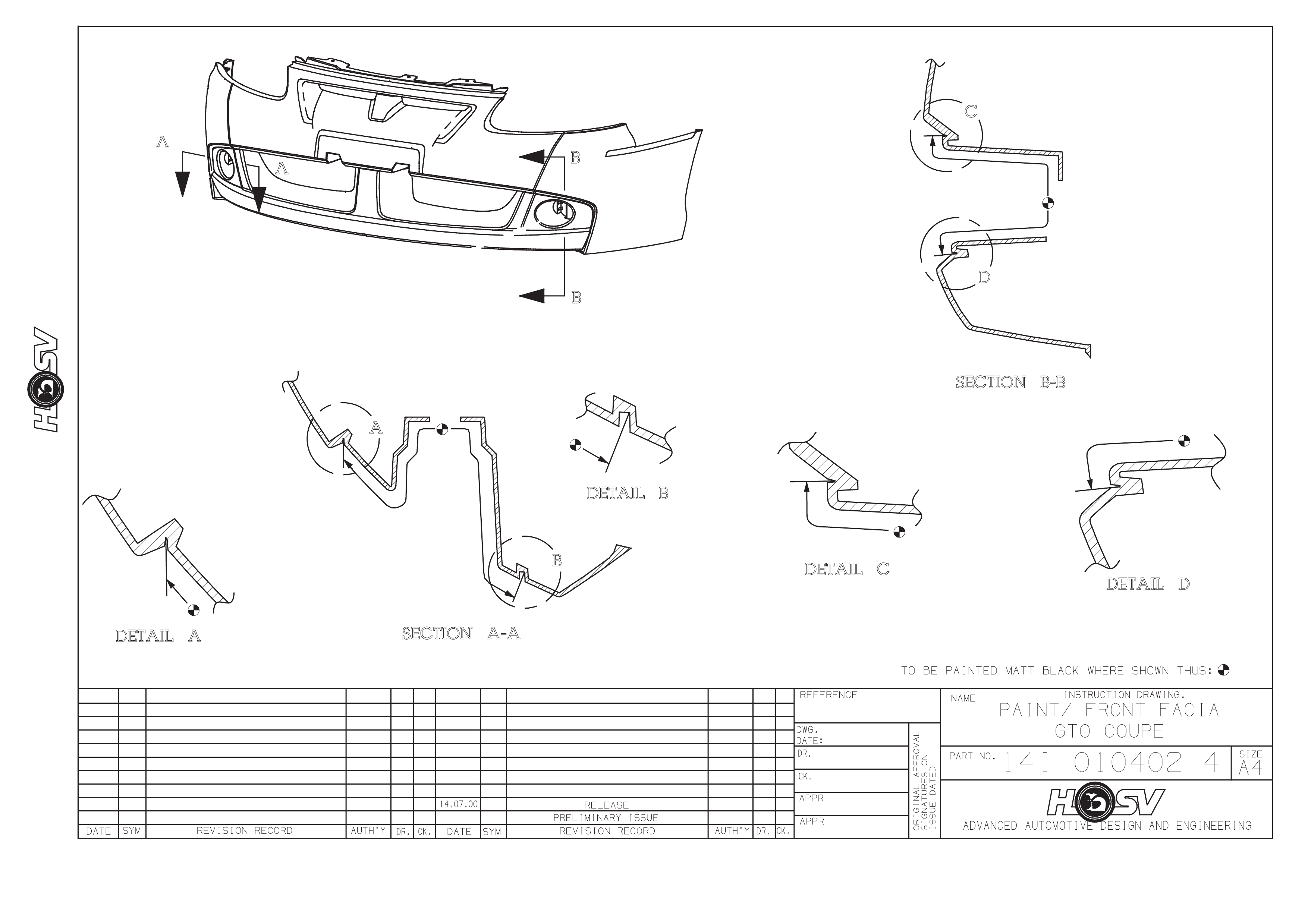
14A-1021101 1 FACIA-FRONT BUMPER BAR* 17
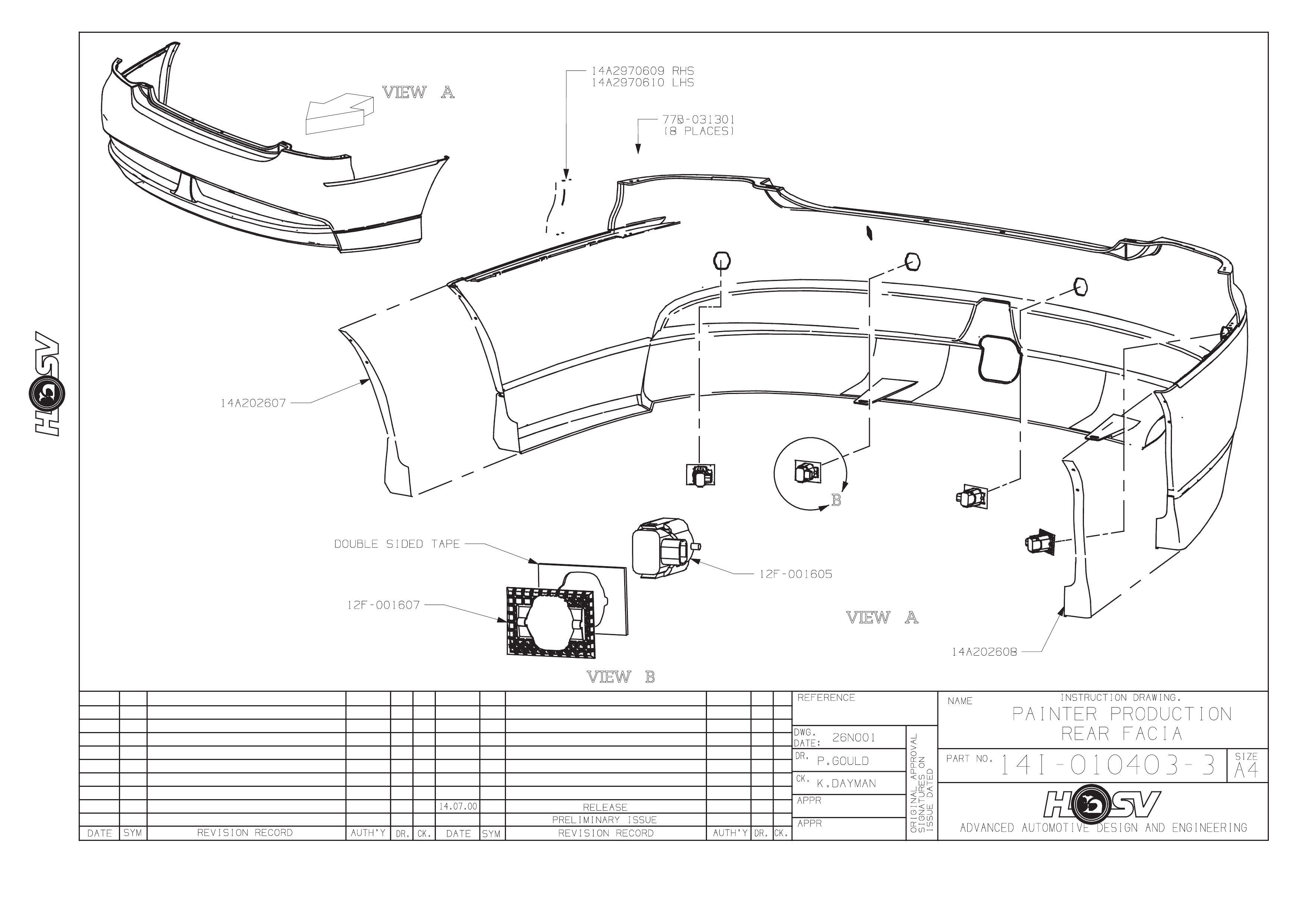
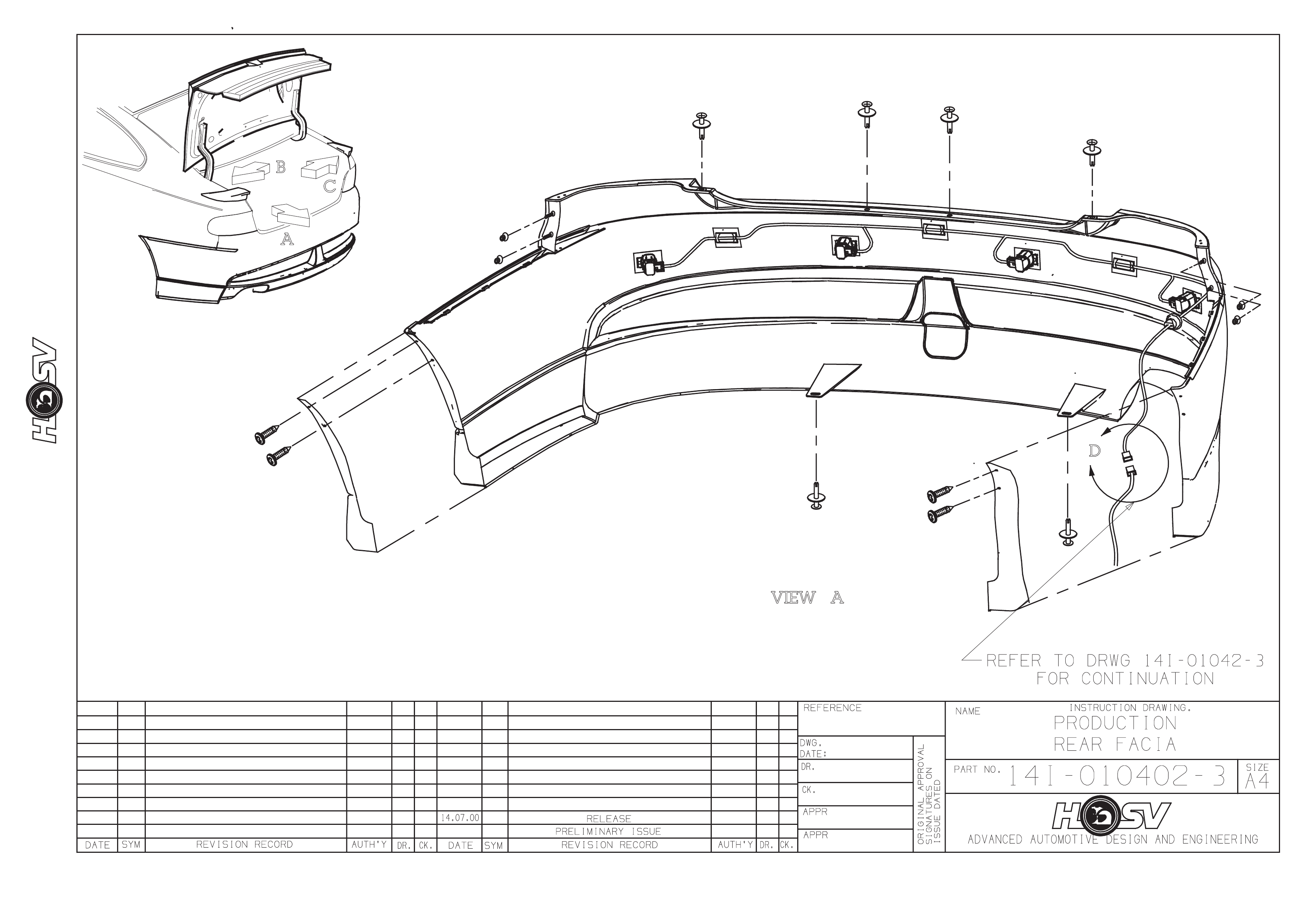
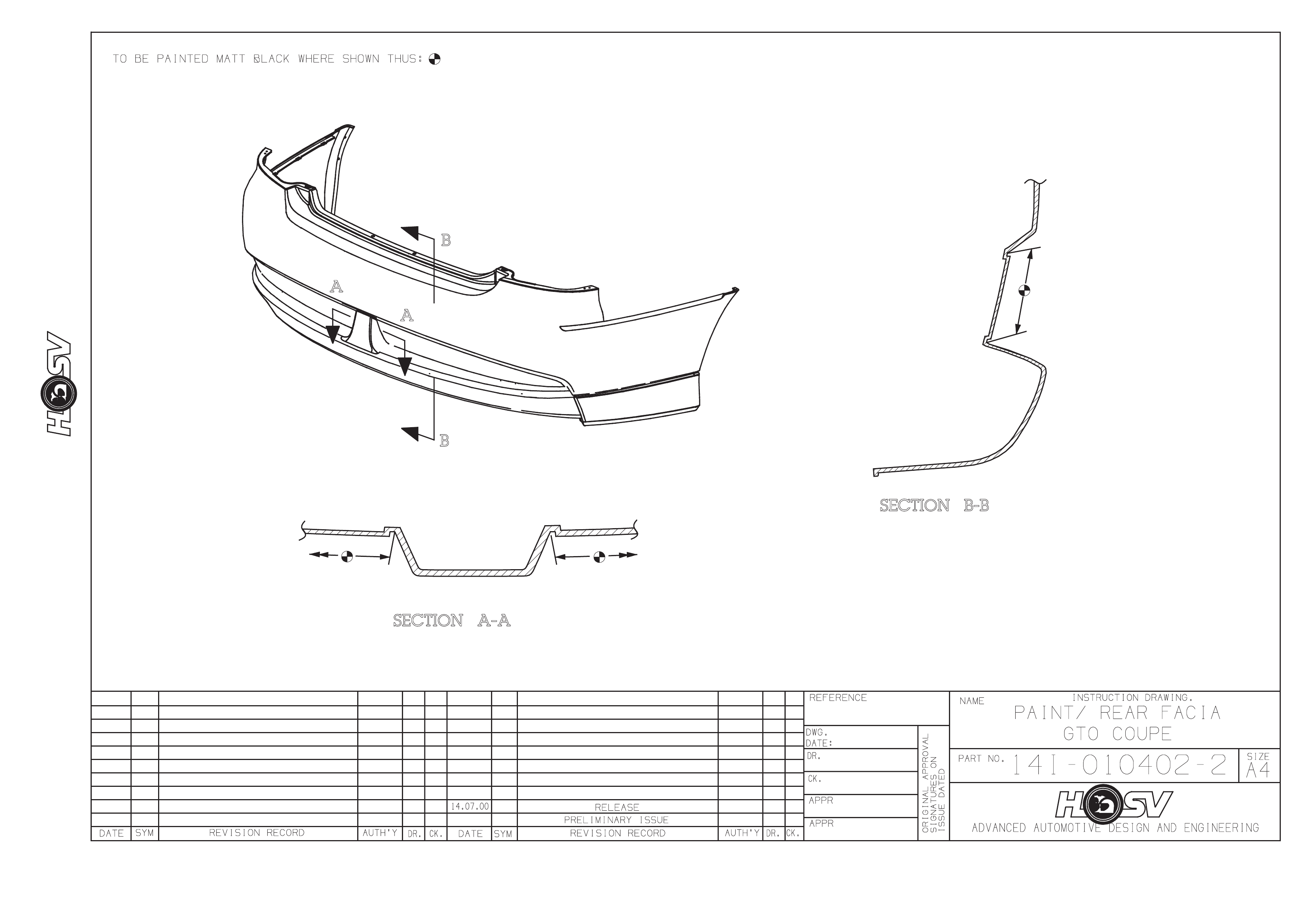
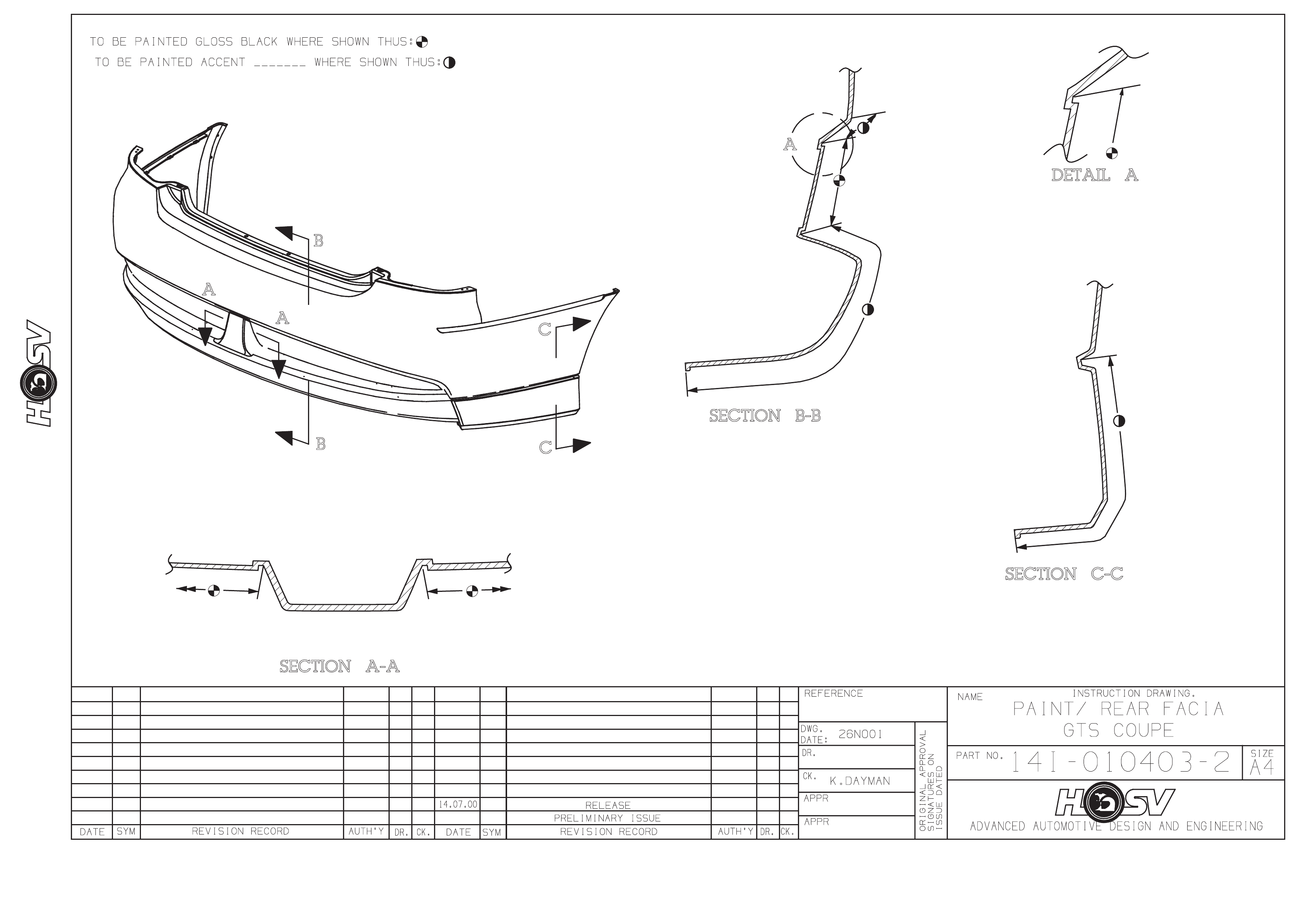
14A-2021101 1 FACIA-REAR BUMPER BAR – CENTRE* 18
14A-1021110 1 MESH-BUMPER OPENING-UPPER
14A-1021111 1 MESH BUMPER OPENING-LWR
14A-1021108 1 PAINT PROTECTOR-FRT RH
14A-1021109 1 PAINT PROTECTOR-FRT LH
10B-970303 1 BADGE – CORPORATE LOGO 24
H08-021102 1 SPOILER – REAR DECKLID – RHS 16
H08-021103 1 SPOILER – REAR DECKLID – LHS 15
E08-021104 1 SPOILER – ROOF 20
E08-021105 1 BADGE COUPE

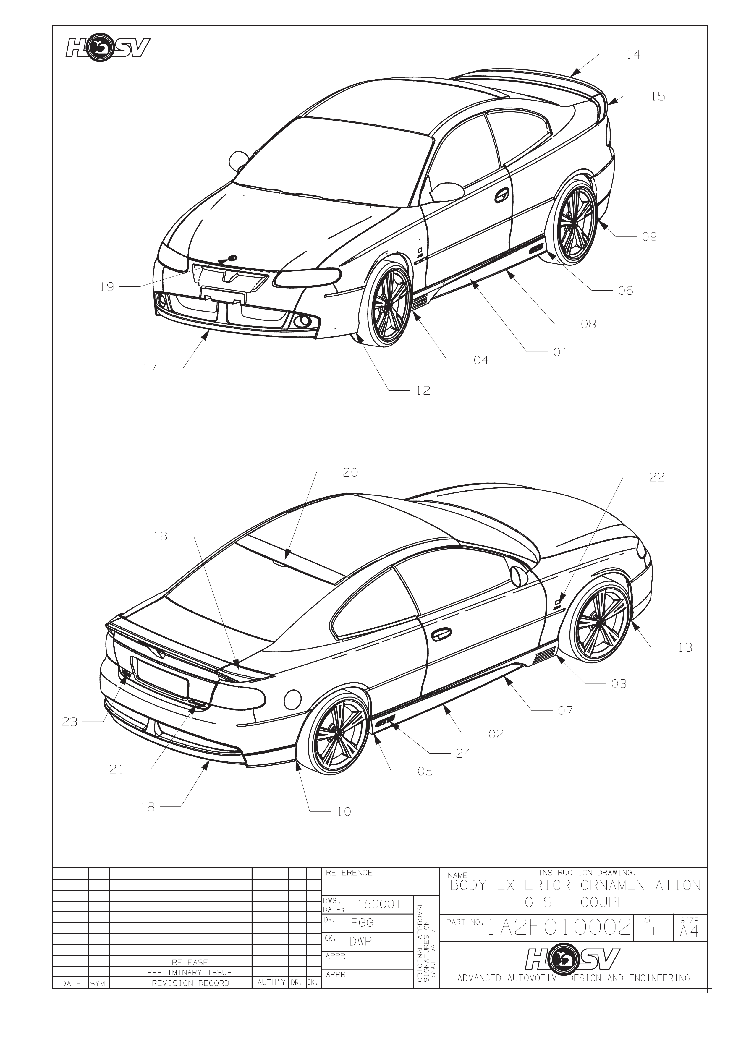
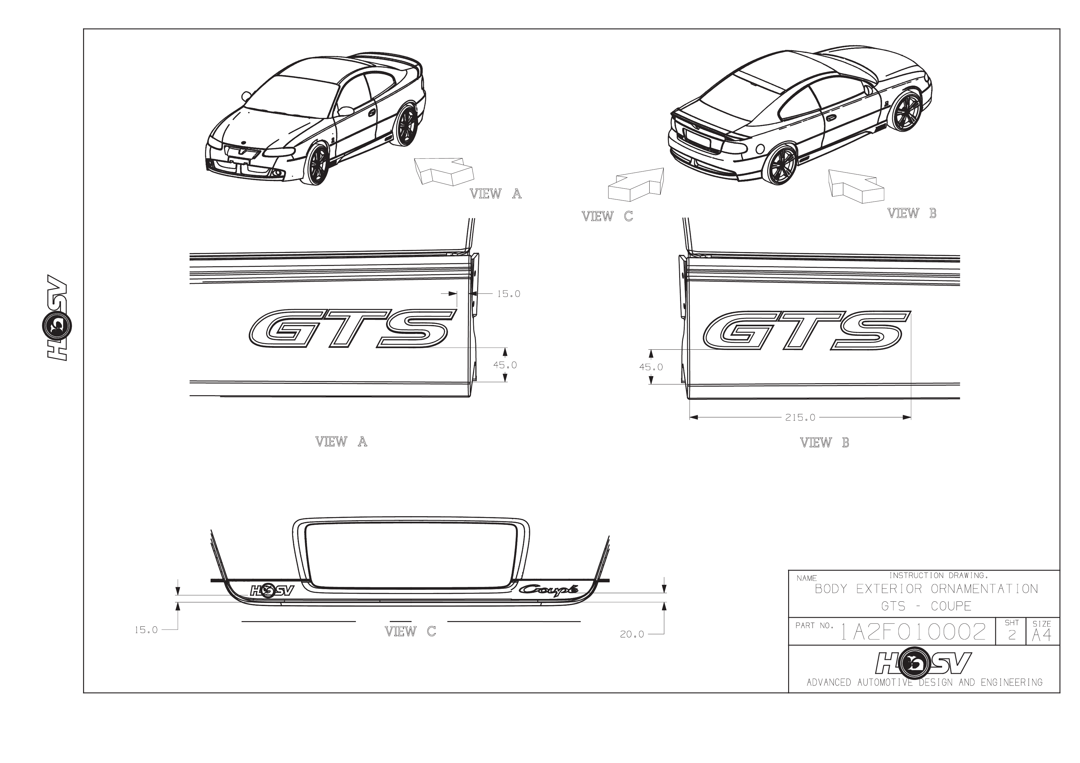
GTS COUPE
CONTENTS OF BODY STYLING PACKAGE
REFER TO DRAWING 1A2F-010002
PART No QTY DESCRIPTIONS FIGURE REF
A08-021101 1 SKIRT - ROCKER-LH* 1
A08-021102 1 SKIRT - ROCKER-RH* 2
A08-021104 1 PAINT PROTECTOR-S/SKIRT FRT RH 3
A08-021103 1 PAINT PROTECTOR-S/SKIRT-FRT LH 4
A08-021106 1 PAINT PROTECTOR-S/SKIRT-RR RH 5
A08-021105 1 PAINT PROTECTOR-S/SKIRT-RR LH 6
A08-021110 1 PAINT PROTECTOR S/SKIRT-SIDE-RH 7
A08-021109 1 PAINT PROTECTOR S/SKIRT-SIDE-LH 8
A08-970607 2 BADGE-HSV CORPORATE LOGO 9
B08-970301 1 BADGE-LION & HELMET (BONNET) 19
H08-021101 1 SPOILER - REAR DECKLID - CENTRE 14
E08-021201 1 BADGE – GTS 24
12C-000601 1 LAMP FOG LH
14A-1000603 2 SPACER FOG LAMP
12E-021101 1 LAMP ASM-HI MOUNT STOP LIGHT 25
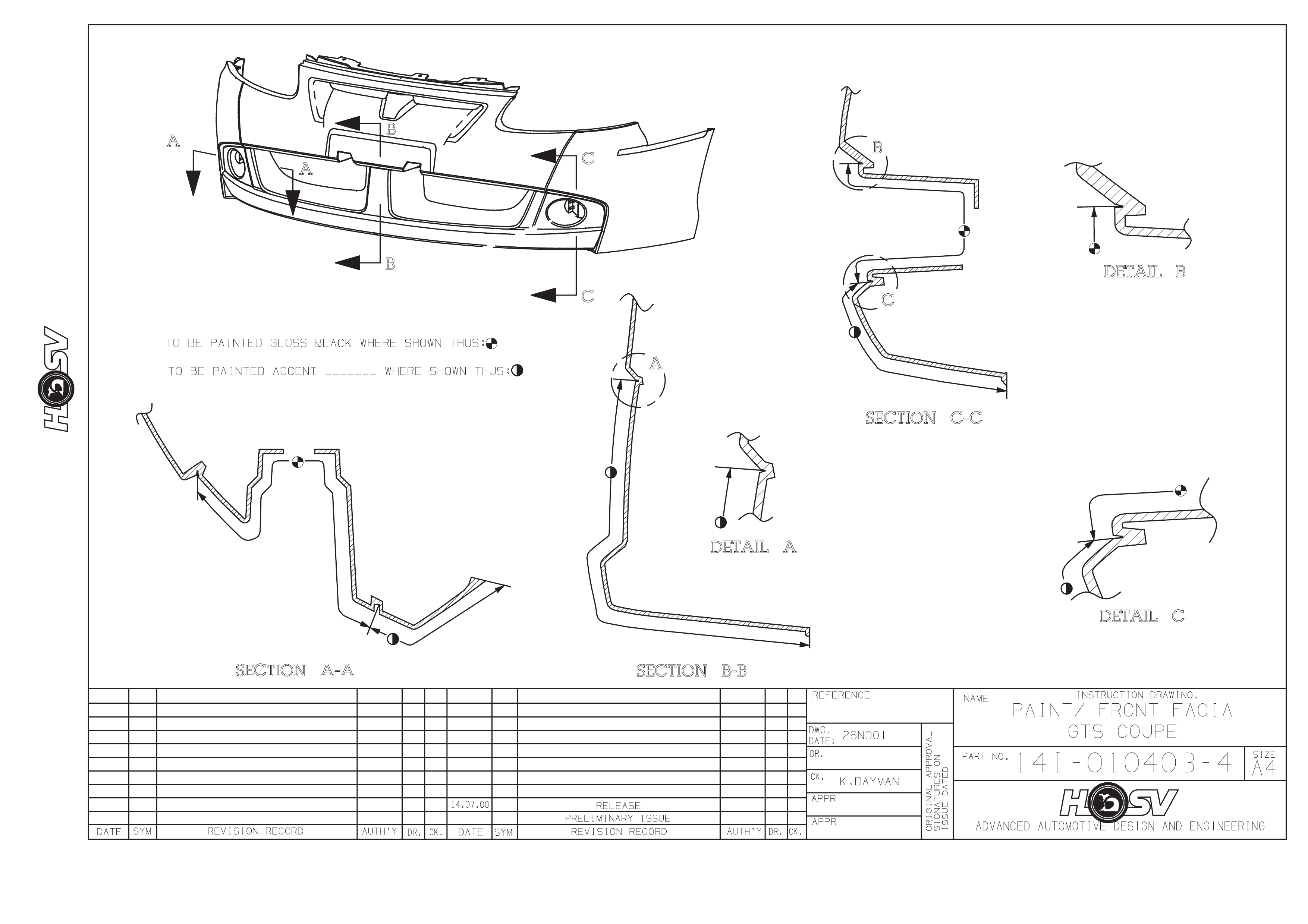
14A-1021101 1 FACIA-FRONT BUMPER BAR* 17
14A-2021101 1 FACIA-REAR BUMPER BAR – CENTRE* 18
14A-1021110 1 MESH-BUMPER OPENING-UPPER
14A-1021111 1 MESH BUMPER OPENING-LWR
14A-1021108 1 PAINT PROTECTOR-FRT RH
14A-1021109 1 PAINT PROTECTOR-FRT LH
10B-970303 1 BADGE – CORPORATE LOGO 24
H08-021102 1 SPOILER – REAR DECKLID – RHS 16
H08-021103 1 SPOILER – REAR DECKLID – LHS 15
E08-021104 1 SPOILER – ROOF 20
E08-021105 1 BADGE COUPE

IMPORTANT
Before performing any Service Operation or other procedure described in this Section, refer to Section 00
CAUTIONS AND NOTES for correct workshop practices with regard to safety and/or property damage.
2. COUPE RE AR SPOILER
SERVICE OPERATIONS
SPOIL ER END S
REMO VAL
1. Apply masking tape to the Rear Quarter Outer Panel. Tape is to be located hard up against the edges of
the spoiler and to extend a width of at least 100mm around the Spoiler Ends.
2. Open the Trunk Lid.
3. Peal back to side trunk lid Rear Quarter Inner Trim to gain access to the Spoiler Ends front attachments.
4. Remove the attaching nut and bracket.
5. Rem ove the two Re ar Upper Spoiler End attaching b olts and t wo brack ets to spoiler a ttaching scr ews and
flat washers.
6. Using a sharp knife cut the Urethane Sealer surrounding the Spoiler Mounting Boss.
7. Slide a Body Filler Applicator or similar stiff plastic plate between the spoiler and body panel to slice
through the Urethane adhesive.
8. Pull the spoiler end away from the Body Panel and carefully cut through any urethane adhesive remaining.
9. Clean the residual Urethane off the body panel with a Profit wheel, decal removing wheel or similar.
INSTALLATION
The installation for the Spoiler Ends is the reverse of the Removal Procedure except that the cutting of the
Urethane Adh es ive is not requir ed.
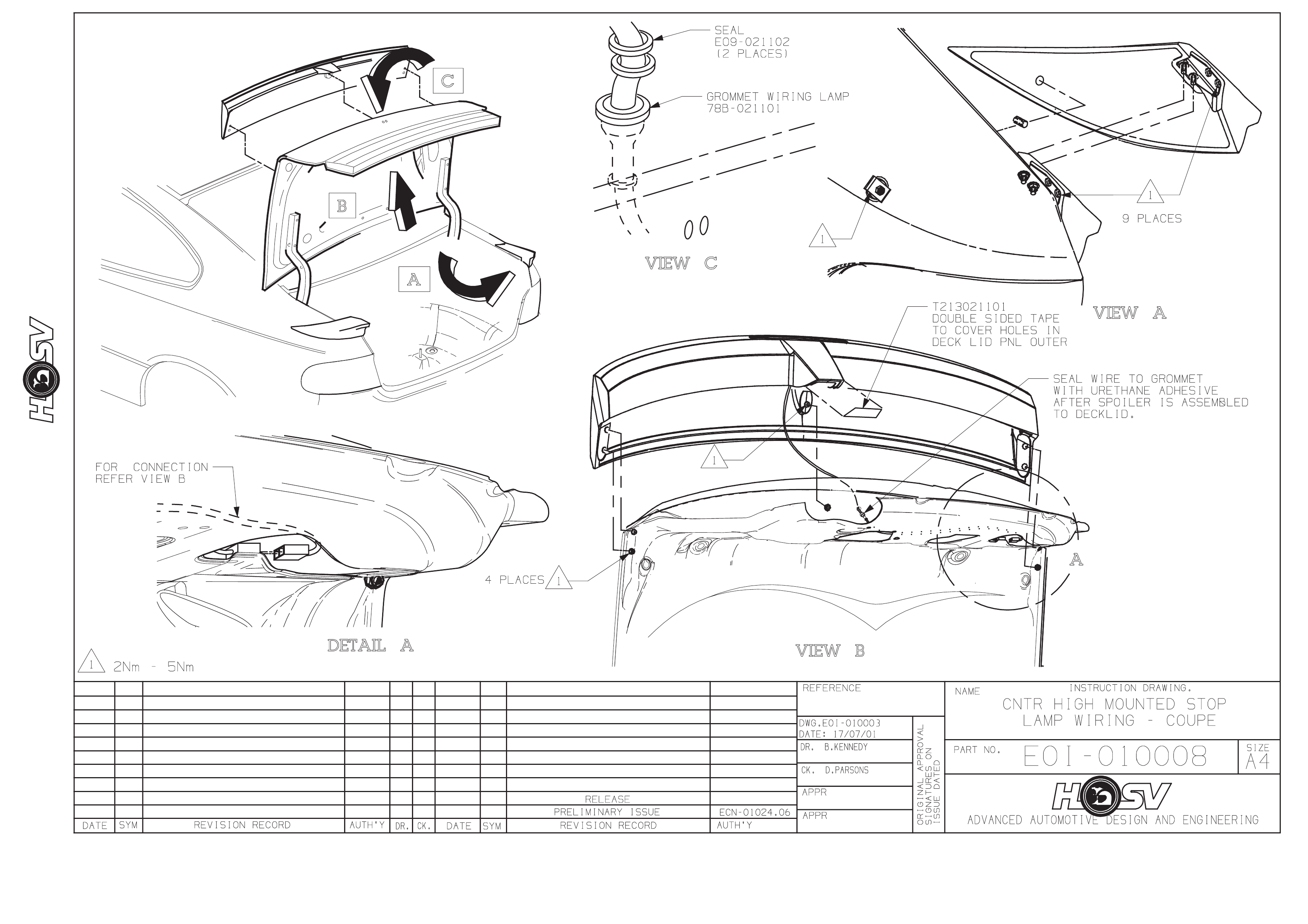
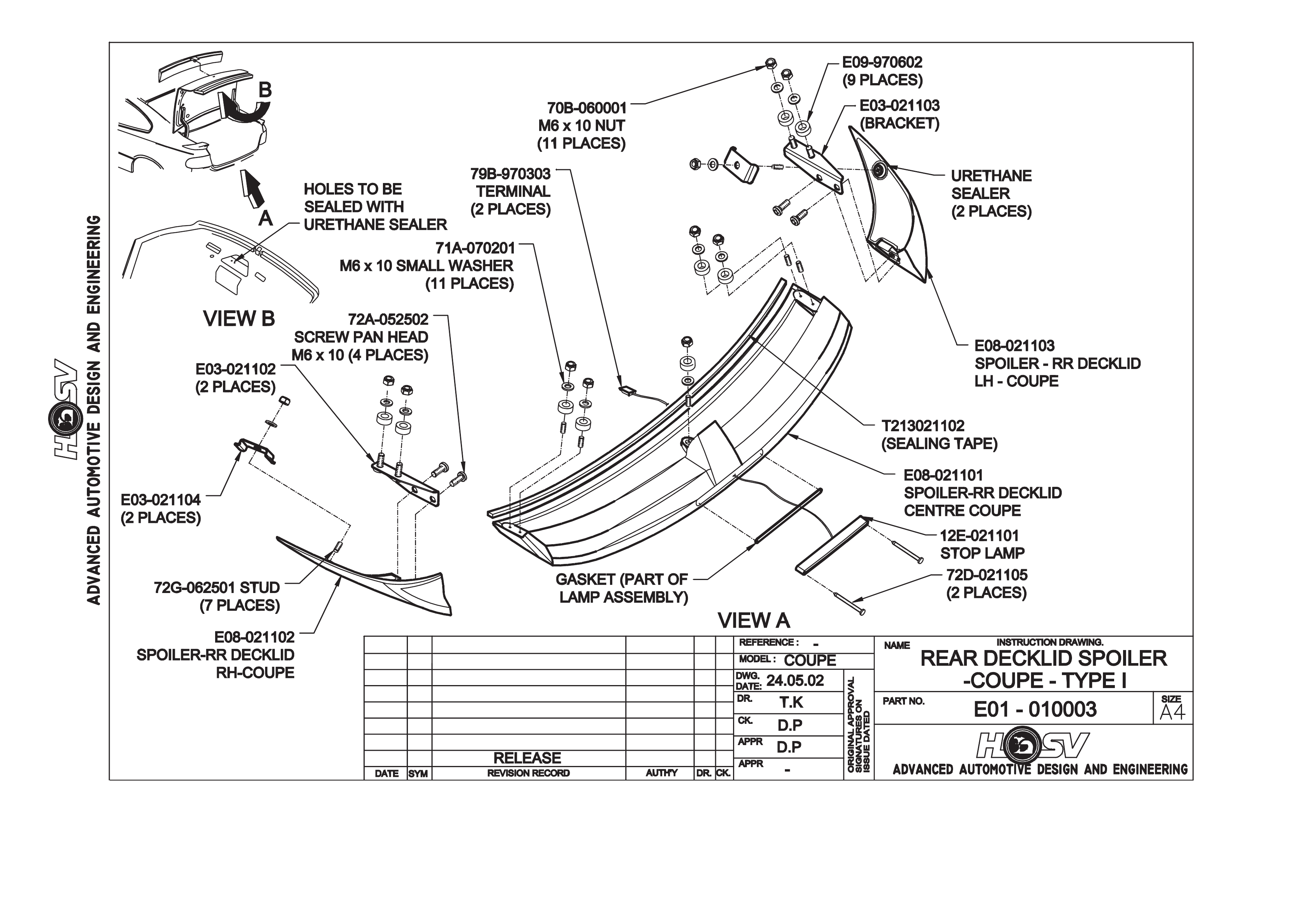
SPOILER CENTRE SECTION
REMO VAL
1. Remove the Deck Lid Inner Trim.
2. Refer to the Electrical Section for the removal of the Centre High Mounted Stop Lamp.
3. Remove the Spoiler Centre mounting flanged nut and stud.
4. Remove the four outer attac hing nuts and washer s (2 per side).
5. Remove the mounting studs from one side of the spoiler.
6. Carefully lift the Spoiler Centre from the Deck Lid.
INSTALLATION
The ins tallation is the r everse of the removal proc edure. Do not attem pt to install the Ce ntre Spoiler with the studs
installed in the spoiler.

IMPORTANT
Before performing any Service Operation or other procedure described in this Section, refer to Section 00
CAUTIONS AND NOTES for correct workshop practices with regard to safety and/or property damage.
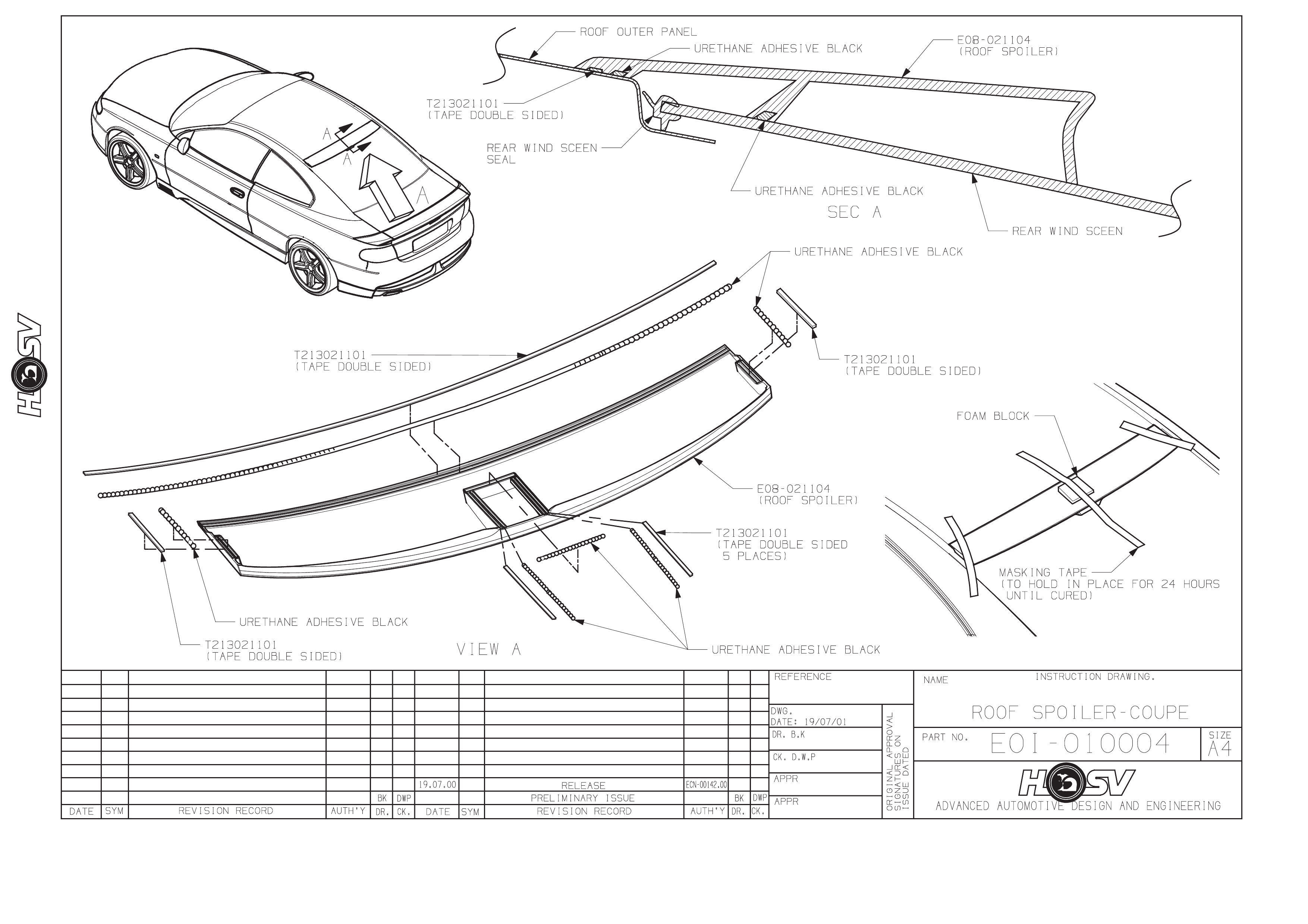
3. ROOF SPOILER
SERVICE OPERATIONS
ROOF SPOILER
REMO VAL
Note: The roof spoiler is ad hered to both the re ar windo w glass and th e rear of the r ear outer panel with Urethane
adhesive. Care must be taken not to damage the paintwork of the vehicle when performing this operation.
1. Apply masking tape up against the front and side edges of the roof spoiler. The tape must extend for a
distance of atleast 75mm away from the edges of the spoiler. This tape is to protect the roof and rear
quarter panels from damage when removing the spoiler and adhesive.
2. Slide a body filler applicator or similar stiff plastic plate between the spoiler and the body panels. Using a
cutting action lik e a knife, break the Urethane adhesive bond. The cutting will need to be done across the
roof panel, down the sides of the glass and also across the glass in the centre of the spoiler. The spoiler
maybe pulled away from the panels for access to the Urethane, but extreme care must be taken to avoid
damage to the panels and paint work.
3. Clean the excess Urethane off the glass and panel work with a profit wheel, decal removing wheel or
similar. Extreme care must be taken to avoid damage to the panels and paint work.
INSTALLATION
1. Remove the protective masking tape used in the removal procedure.
2. Clean the attaching area with Urethane cleaner and prime the contact area.
3. W ith the assistance of another person l ocate the s poiler centr ally between t he roof mouldings (at the sides
of the rear glass) and align the spoiler side notches (located towards the top edge of the spoiler) with the
top rear window glass moulding.
4. Using a chin a gra ph penci l (wh ite) or sim ilar place alig nm ent mark s on the s poiler and the b od y. These will
be used for location of the spoiler on the vehicle when the adhesive is applied.
5. Place the new spoiler upside down on a protective cloth and apply Urethane adhesive along the front edge,
sides and central leg as shown on drawing E0I-010004.
6. Locate the spoiler in position on the vehicle using the previously applied location marks (china graph
pencil).
7. Take the spoiler to hold it in position while the Urethane adhesive cures refer drawing E0I-010004. The
cure time for the Urethane adhesive is 24 hours, it is not recommended that the tape be removed or
the vehicle be driven in this period.
8. Remove the tape from the spoiler and the vehicle after the 24-hour cure time and polish the area to remove
any foreign m atter, which may have been lef t by this procedure.