
SECTION I – LIGHTING SYSTEM
IMPORTANT
Before performing any Service Operation or other procedure described in this Section, refer to Section 00
CAUTIONS AND NOTES for correct workshop practices with regard to safety and/or property damage.
1. ELECTRICAL SYSTEM
1.1 GENERAL INFORM ATION
The elec tric a l s ystem as f itted to the HS V G T O and GT S Coupe Series M ode ls c ar ries o ver f r om Holden V2 Coup e
Series Models. Refer to Section 12 of the Holden V2 Coupe Series Service Information.

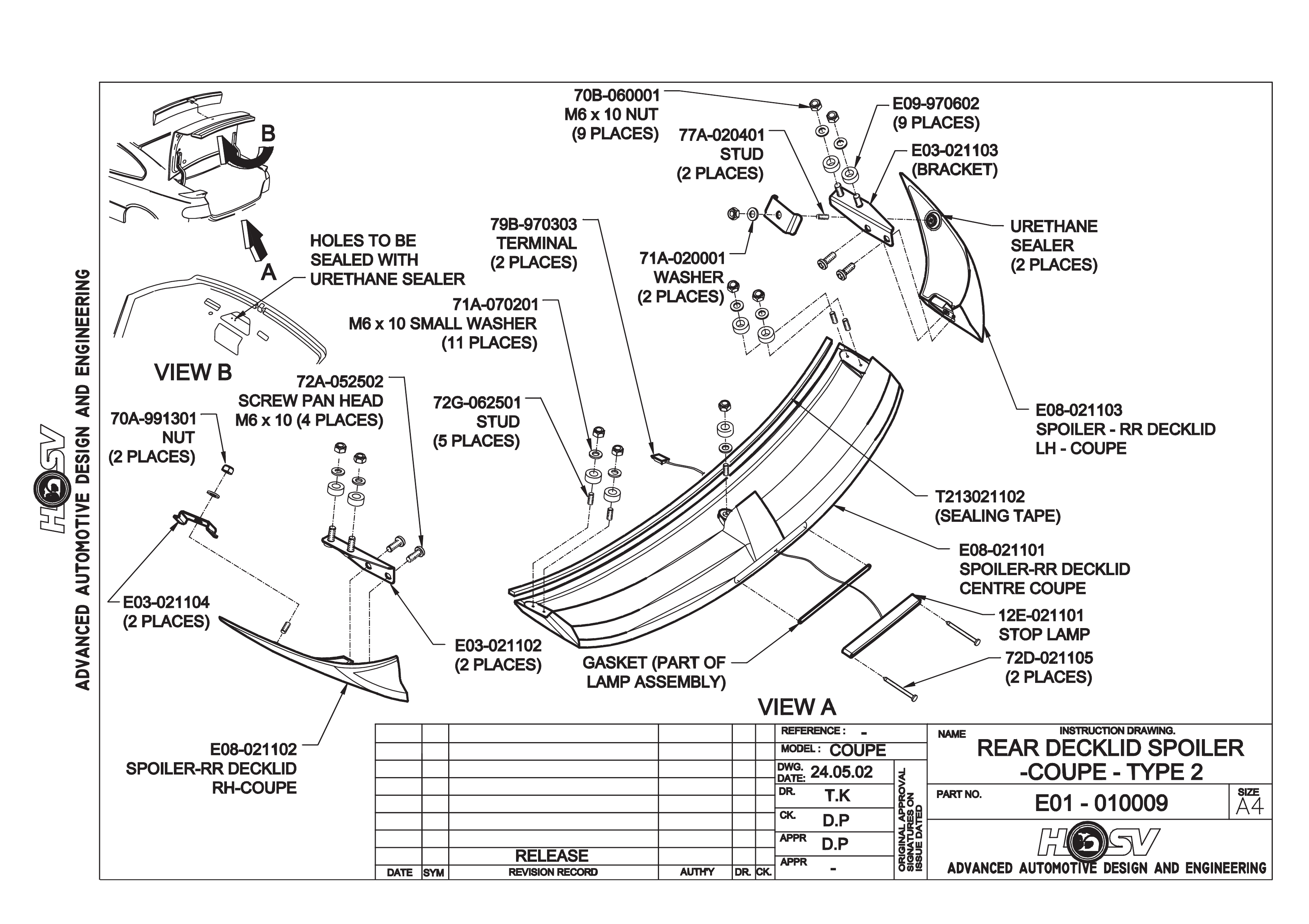
2. HSV REAR SPOILER
The HSV GTO and GTS Coupe Series Models are fitted with Rear Spoilers incorporating a Centre High Mounted
Stop Lamp (CHMSL).
2.2 SERVICE OPERATIONS
To service the HSV Coupe Deck Lid Spoiler Mounted Stop Lamp the following procedure is to be followed.
CENTRE HIGH MOUNTED STOP LAMP REMOVAL AND REPLACEMENT
1. Open Deck Lid.
2. Disconnect vehic l es Batter y Leads.
3. Remove the Deck Lid inner trim retainers and trim panel.
4. Disengage the Centre High Mounted Stop Lamp (CHMSL) Harness Connector from the Deck Lid Harness
Connector, this is mounted on the right hand side of the Deck Lid Inner Panel. Refer to Drawing No.
EOI-010009 View A, refer Section B - Body of this manual.
5. Remove CHMSL Wires and Terminals from the CHMSL Connector taking note of the wire colours and their
locations.
6. Remove the two Lamp Retaining Screws.
7. The Lam p wiring passes th rough a CHMSL g asket and a grom met located in the Deck Lid Outer Panel (under
the spoiler). The wire is sealed to the grommet with Urethane Sealer, this seal between the grommet and the
wire m ust be broken to all ow the lam p wiring to m ove. T his will allow fr ee play in the wir ing so the lam p can be
pulled out of its mounting cavity in the Spoiler giving access to the wiring at the rear of the lamp.
8. Cut the Lamp wiring leaving a 50mm length of wire protruding from the Spoiler and discard the lamp and
gasket.
9. Strip 12mm of insulation off the end of the two lamp wires now protruding from the spoiler lam p cavity and tin
with solder.
CENTRE HIGH MOUNTED STOP LAMP INSTALLATION
10. Install the Lamp Gasket to the lamp with the wiring passing through its access hole.
11. Strip 12 m m of ins ulatio n of f the end of the r ep lacement lamp wires and s o lder j oin thes e to th e c ut orig ina l l am p
wires protr u din g f r om the Spoiler . Ens ure that an ex c ess of s older is not us ed, but the j oi nt is s trong as it wil l be
used to pu ll the wir es from the new lam p through the Rear Spoiler and Dec k Lid Outer Panel us ing the ori ginal
lamp wires.
12. Carefully pull the wires through the Spoiler and Deck Lid Outer Panel while feeding the new lamp wiring
through. D o no t us e ex ces s ive force if the wiring s tops or app ears to s n ag. If this is enc ount er ed the Sp oi ler wil l
have to be removed to reinstall the wiring and lamp assembly. Refer to Drawing No. EOI-010003 refer to
Section B - Body of this manual. Ensure that the new Lamp Gasket is located between the Lamp Base and
the bottom of the Spoiler Recess and is not kinked or buckled, and that the wiring passes through the access
hole in the Gasket.
13. Install the Lamp and Gasket into the Spoiler Recess.
14. When inserting the CHMSL into the Recess take care not to damage the wiring and gasket, fasten the
attaching screws.
15. Once installed cut the CHMSL wires to a length that allows the wires to run to the Connector located on the
Deck Lid Inner Panel.
16. Strip the insulation off the wires and attach the new Terminals provided, install the Terminals into the Connector
housing using the wiring colours and locations previously noted in the removal procedure.
17. Assemble the CHMSL Connector and wiring with the Deck Lid Connector and Harness assembly.
18. Reconnect the Battery Terminals and check the function of the Lamp.
19. If the lam p does not functio n it is possible th at the wires have b een incorrec tly installed i n their locatio ns in the
connector body. Refer to the wiring and colour locations noted prior to the removal procedure.
20. Seal the CHMSL Wiring where it passes through the Deck Lid Grommet with Urethane sealer. Refer Drawing
No. EOI-010009 View B.
21. Install the Deck Lid Inner Panel Trim and Retainers.
22. Clean and polish all areas where work has been conducted.

3. INSTRUMENTATION
3.1 GENERAL
A specific Instrument Cluster designed by HSV is fitted to all HSV GTO and GTS Coupe Models. The cluster
includes a HS V speedom eter with an o perating ran ge extend ing to 250 km /h. The cluster incorporates a blue fac e,
red needles and war nin g lights and, when il luminated , green numerals and letter s .
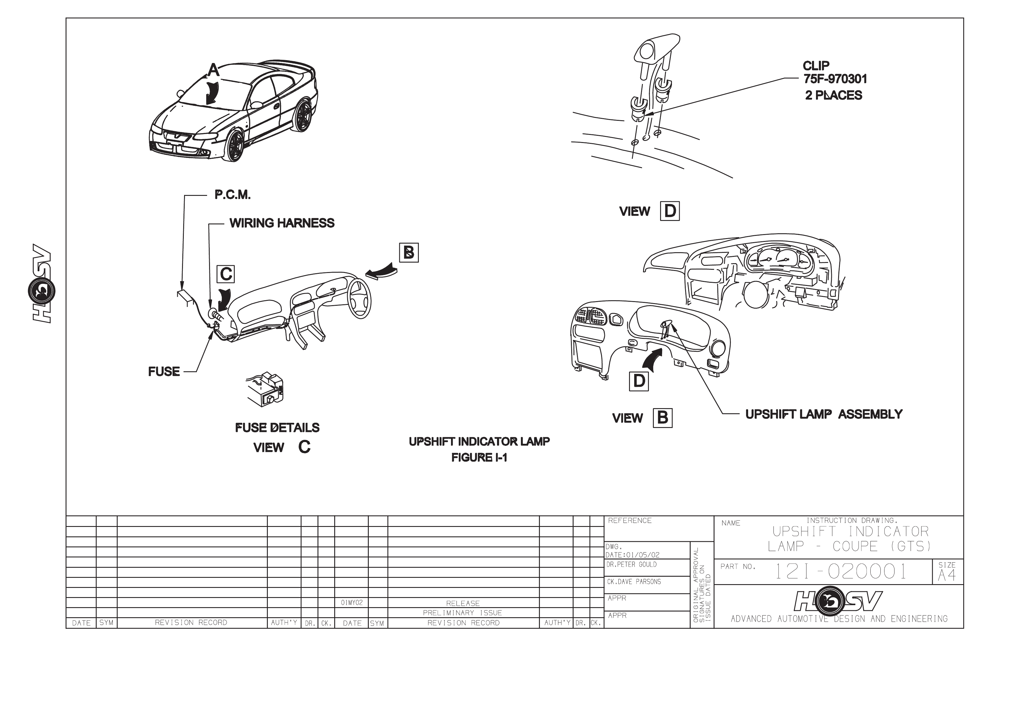
HSV GTS Coupe is fitted with an upshift indicator. This indicator is controlled by the Engine Control Unit and the
LED and buzzer giving the driver an indication when to upshift to achieve maximum performance. The shift
indicator wil l operat e:
§ When engine coolant is < 85°C at 4,000 RPM.
§ When engine coolant is > 85°C:
- 1st gear 6,050 RPM
- 2nd gear 6,200 RPM
- 3rd gear 6,300 RPM
- 4th gear 6,300 RPM
- 5th gear 6,300 RPM
The harness has an inline fuse (3A) which is located underneath the glove compartment near the firewall. The
power feed for the indicator is fused by F12, turn signal (15A). Refer to Figure I-1.

3.2 SERVICE OPERATIONS
The HSV Ins trument Clus te r and the s tan dar d Ho ld en V2 S eries Cou pe clus t er us e the s ame m ounting f ixtur es and
fastener s. Rem ove, service and refit the H SV Instr ument Clus ter in acc ordance wi th the proced ures detai led in the
Holden V2 Coupe Ser i es Service Information, refer to Section 12C – Instruments, Wipers/Washers & Horn.
For service of the upshift indicator lamp refer to Drawing 12I-020001.

4. PARKING SENSORS
4.1 GENERAL
The HSV Park ing sensor s ystem as sists the driver while reversi ng into a park ing space by warnin g of obstac les at
the rear of the vehicle. Please remember that there is no substitute for driver care while reversing. The
responsibility for recognising and assessing obstacles remains with the driver. Reversing safely can only
be achieved by adopting a responsible driving style. A prompt warning is only possible if the vehicle is
reversed slowly.
The parking sensor system is equipped with a visual and audible indicator, which is located on the parcel tray trim.
The parking sensor system switches on automatically when the ignition is on and reverse gear is selected. T his is
indicate d by a sing le, brief tone accom panied b y all LED’s o n the indic ator bri efly illum inating sim ultaneous ly when
reverse is selected. An obstacle is recognised from approximately 150 cm between the obstacle and the rear
bumper. If this distance is reduced the frequency of warning tones and number of LED’s illuminated will increase.
The tone will repeat faster and faster until it becomes a continuous tone and all of the LED’s are illuminated at
which point the distance to the obstacle will be less than 30 cm.
An overri de s witch has b een provid ed to s witch off the s ystem to avoi d fals e alar m ing when a tr ailer or bic ycle rac k
is attached to the vehicle. The override switch is located under the parcel tray in the boot on the left hand side.
4.2 PARKING SENSOR SYSTEM DIAGNOSTICS
NORMAL OPERATION
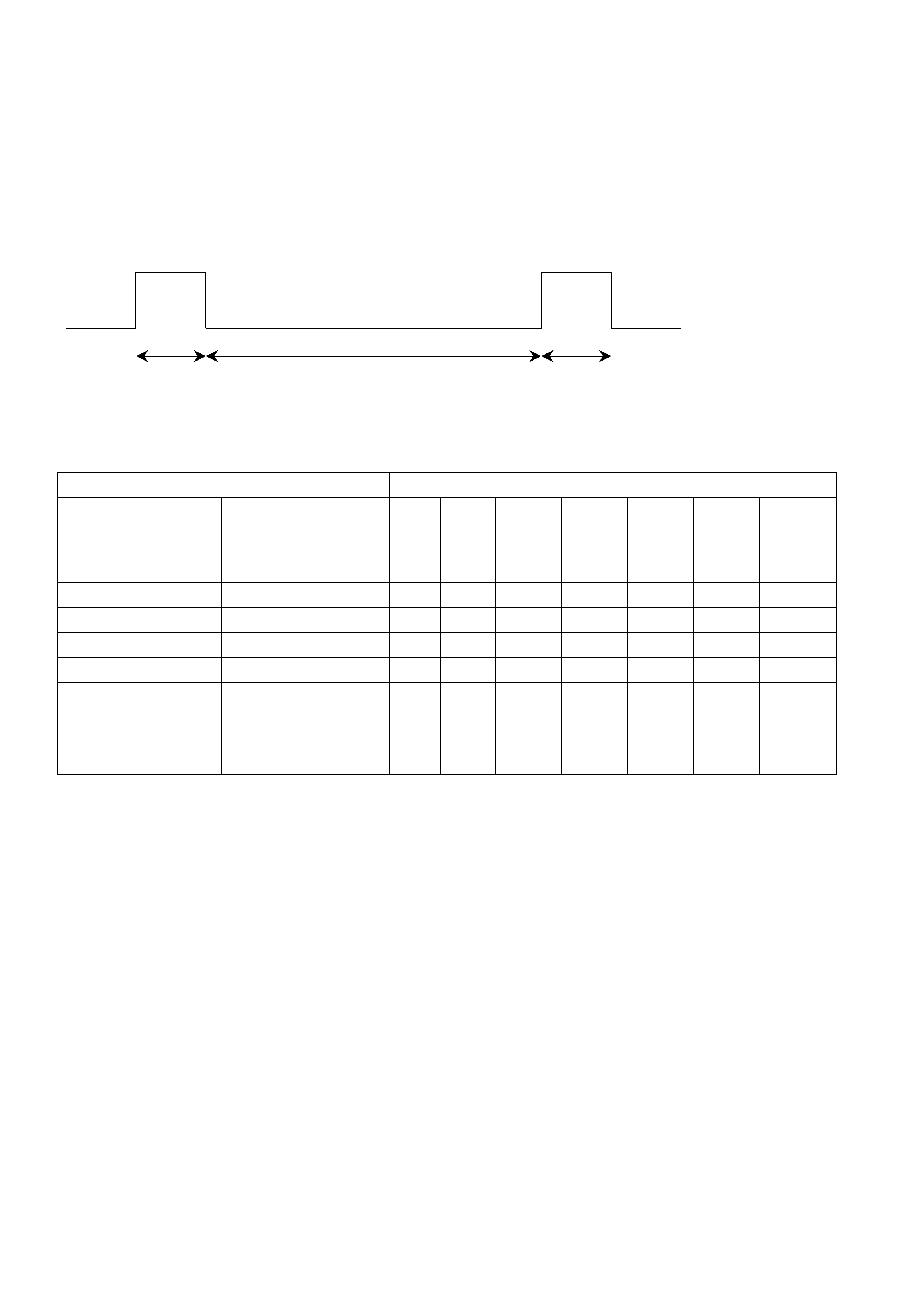
In normal operation, with no obstacles within two metres of the rear of the vehicle, the parking sensor will issue a
single short tone (0.5 sec) and illuminate all of the LED’s on the indicator (also for 0.5 sec) when reverse gear is
first selected with ignition on. If there are obstacles behind the vehicle then the audible sound will be a series of
beeps or a continuous tone dependant on distance to object. The visual indication will be a number of LED’s
illuminated increasing as the distance to the object decreases. Refer to table 1.
Tone on Tone off duration depending on Tone on
75 ms distance to obstacle 75ms
ACOUSTICS OPTICS
Obstacle
Distance Tone
frequency Tone On Tone
Off Red Red Yellow Yellow Green Green
30 cm 1200 Hz Continuous tone l l l l l l all
blinking
40 cm 1200 Hz 75 ms 75 ms l l l l l l
60 cm 1200 Hz 75 ms 150 ms l l l l l
80 cm 1200 Hz 75 ms 225 ms l l l l
100 cm 1200 Hz 75 ms 300 ms l l l
120 cm 1200 Hz No tone l l
150 cm 1200 Hz No tone l
Read
tone 1200 Hz 0.5 sec l l l l l l
TABLE 1
FAULT DIAGNOSIS
1. No Tone At Switch On
If no tone is h eard when r everse ge ar selecte d with ig nition on, c heck park sensor over ride sw itch which is locate d
under the par cel tr a y in the boot on t he left hand s i de . If c hangin g switch pos i ti on does n ot r es u lt i n s witch on tone,
check operation of r everse lights – par king s ensor is p owered f rom the rever se lam p c ircuit. If park lam ps OK, then
check condition of par k sensor harness connectio n at right hand ta il lamp c onnector. T he red lead connec ts to the
reverse lamp circuit (for 12V into park sensor module) and the brown lead connects to the lamps ground circuit.
2. Short High Tone Followed By Continuous Low Tone
It will be n ecessary to view the visual indicator for the diagnostic procedure. T his indicator incorporates a sp eaker
for diagnostic tones and is located on the parcel tray.
W hen reverse gear is selec ted with ignition on, a sh ort high to ne ma y be heard fo llowed b y a conti nuous low tone .
This indicates that the park sensor system self-diagnosis has detected a problem. Switch off the ignition and
remove the system-coding plug from its socket to enter s ystem diagnostics. The system -coding plug is located o n
the park sensor wiring harness between th e left hand tail lam p and the park sensor module. The plug is similar in
appearance to an automotive fuse but contains a resistor. Do not replace this plug with a fuse.
NB. It is essential to have at least two metres of clear space behind the vehicle while in diagnostic m ode to avoid
any interference from detected objects. Switch the ignition on again (with reverse gear selected). If there is a
defectiv e sensor, it will be indicat ed as shown in the table be low. Sensor 1 is located on the right ha nd side of the
vehicle and sensor 4 on the left.
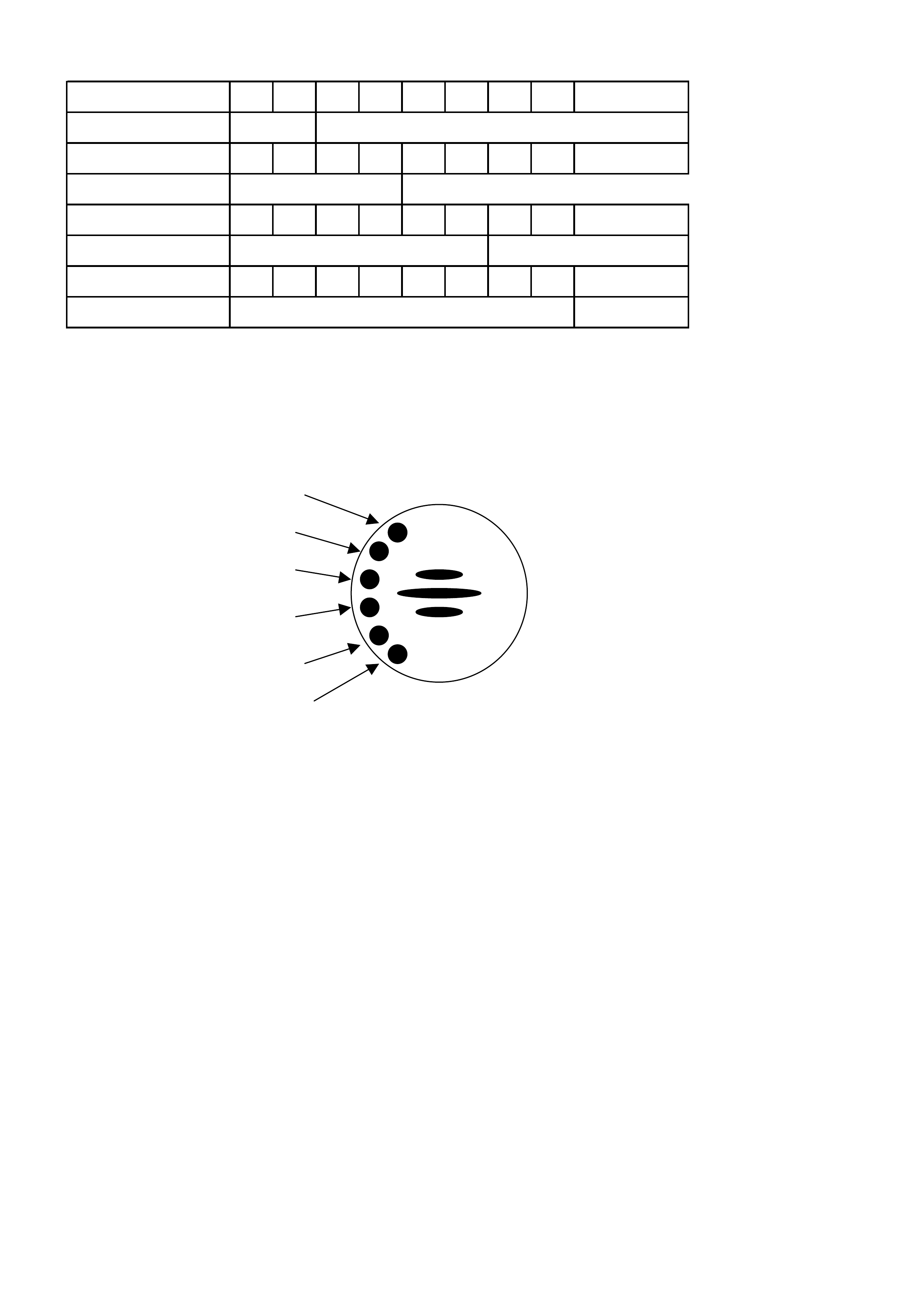
Fault Sensor 1 •¢¨
LED 1 On
Fault Sensor 2 •¢•¢¨
Fault Sensor 3 •¢•¢•¢¨
LED 3 Of
f
Fault Sensor 4 •¢•¢•¢•¢¨
LED 4 Of
f
LED 4 On
LED 1 Of
f
LED 2 Of
f
LED 2 On
LED 3 On
• Tone on, 600 Hz for 1 second
¢ Tone off for 1 second
¨ Sequence end, 2 seconds
If several sensors are faulty, the error codes on the individual sensors are displayed in turn separated by the
2 second ending sequence. A faulty plug or wiring harness will also be indicated as a sensor fault.
If no sensor is faulty, the low warning tone will be cycled for 3 seconds on and 3 seconds off to indicate that the
coding plug has been removed.
If there is a fault with the Control Unit, the error display will be as follows:
Opening sequence low warning tone (600 Hz) and two red LEDs followed by 1 second off
Error sequence low warning tone (600 Hz) and two yellow LEDs
This indicates a fault in the control unit hardware, power supply (reverse lamp voltage) sensor voltage or coding
plug short circuit.
LED 1 red
LED 2 red
LED 3 yellow
LED 4 yellow
LED 5 green
LED 6 green