
SECTION J – OPTIONS
IMPORTANT
Before performing any Service Operation or other procedure described in this Section, refer to Section 00
CAUTIONS AND NOTES for correct workshop practices with regard to safety and/or property damage.
PURPOSE
The purpose of this supplement is to provide information on the special options and accessories fitted to the HSV
GT O and GTS Coupe m odels. T his inform ation is designed to supplem ent that co ntained in th e Holden V2 Coupe
Series Service Information, and details are given where differences occur between the HSV models and standard
Holden models. A series of instruction drawings detail the design changes and indicate specific part numbers,
fitting instructions and relevant notes for vehicle servicing.
NOTE:
If specific technical data on a HSV model is not contained in this supplement, obtain data for that model from the
relevant Holden V 2 Coupe s er ies S er vic e I nf o rm ation Sup p lement. Ref er enc es are made thro ugh out th is s ection to
Holden Service Information, to assist in providing information for specific service operations.
CAUTION:
W hen hoisting (or jac king) HSV models , ensure that the lifting h ead of the hoist l ifts on the chass is before the ar m
of the hoist contacts the side-skirt


1.2 SERVICE OPERATIONS
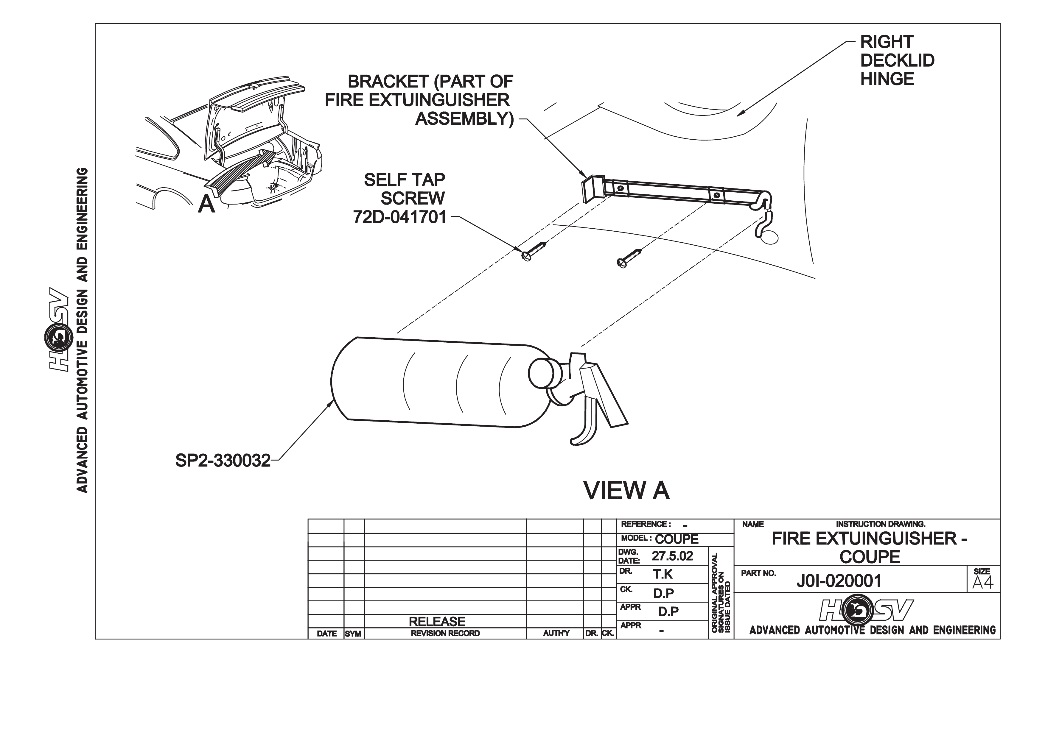
The fire extinguisher should be subjected to a regular visual inspection in accordance with the instructions on the
extinguis her. Par tic ularl y, the extin guisher should be ins pected f or dam age and to ensure tha t the inte gral pr essur e
gauge registers the appropriate internal pressure. When discharged or when the internal pressure is outside the
prescribed limits, the extinguishers should be serviced and re-charged by an appropriate supplier. New
extinguishers are available through the HSV spare parts system.

2. HSV EMBEDDED SECURITY SYSTEM GTO AND GTS COUPE
2.1 GENERAL
The new HSV Em bedded Secur ity System (ESS) is fitted as standar d equipm ent to all HSV GTO and GT S Coupe
models. The ESS is a micro-processor controlled immobiliser, which automatically interrupts essential electrical
circuits when in “armed mode”. The ESS stores the BCM’s security code and when the car is started it reads this
code from the SCI bus. If this code is different from the stored one the ESS ent ers armed mode and prevents the
vehicle from starting.

2.2 LINKING THE ESS TO A NEW BCM AT THE CAR DEALER –
BCM IN WARRANTY
If the BCM requires replac ement within the BCM warrant y period, the Dealer shall be supplied with a replacem ent
BCM and two new keys, all programmed with the same BCM security code as the original BCM. In this case, the
replacement BCM and new keys are simply fitted to the vehicle. No ESS specific requirements are needed.

2.3 LINKING THE ESS TO A NEW BCM AT THE CAR DEALER –
BCM OUT OF WARRANTY
W hen a BCM requ ires r eplac ement outs ide the BCM warranty period th e Dea ler s hall n ee d to obt ai n a r epl a cem ent
BCM and keys from Holden’s Service Parts Operation (HSPO). The replacement BCM and Keys will not contain
the same BCM Security Code as the original BCM.
When a new BCM with different BCM security code is fitted to the vehicle, the dealer will have to do the following:
- Link the BCM and PCM.
- Program a new key to the BCM.
TECH 2 m ust be connected to the vehicle diagnos tic connector whilst the k ey is being progr ammed and/or ESS is
being link ed to the vehicl e. T he Link Enable Proc edure is required to be per form ed twice to allow a n all new k ey to
be programmed and also allow the ESS learn to learn the BCM security code. The procedure for programming a
new key to a new BCM and linking the ESS to the vehicle is as follows:
1. Fit new BCM to the vehicle.
2. Ensure driver's door is closed, driver's door is unlocked, and wash-wipe switch is off.
3. Place new key into the ignition barrel.
4. Turn ignition on. Verify ESS beeps 5 times.
5. TECH2 must be operating in the “Normal Mode” submenu of the Body Control Module sub-menu.
6. Perform the Link Enable Procedure (s ee Section 2.5). W ait 1 sec ond between eac h lock unlock to ensure the
door lock actuators function correctly during this procedure.
7. Verify that the ESS beeps twice. TECH2 reports ignition is at 12Vdc. The ESS has now entered “Key
Programming mode”.
8. Select Key Programming function – “All New Key” - from the security sub-menu in the body menu of the
TECH2. Enter BCM security code as requested by TECH2. Complete key programming as requested by
TECH2.
9. Turn ignition off and wait for 2 seconds. Turn ignition on.
10. Verify ESS beeps 5 times. (At this stage the ESS is in “armed mode”).
11. TECH2 must be operating in the “Normal Mode” submenu of the Body Control Module sub-menu.
12. Perform the Link Enable Procedure (s ee Section 2.5) . W ait 1 s econd between eac h lock unlock to ensure the
door lock actuators function correctly during this procedure.
13. Verify that the ESS beeps twice. TECH2 reports ignition is at 12Vdc.
14. Link the PCM to the BCM using TECH2. ESS beeps twice (ESS has now learned the BCM security code).
15. Turn ignition off. Wait until TECH2 programming is complete.
16. Turn ignition on.
17. Turn ignition off. Wait 2 seconds.
18. Turn ignition on.
19. Verify ESS beeps once. The ESS is now operating in “normal mode”.
20. Crank engine. Verify vehicle starts as normal.

2.4 KEY P ROGRAMMING MODE
Once the ESS has been placed into key programming mode the ESS will behave as if in “sleep mode” for one
ignition c ycle only. This allows for the one ignition c yc le that is requ ired to program a new key to a new or e xisting
BCM. The ESS will enter “norm al m ode” for the next ignition cyc le. If the BCM is a new BCM in the vehicle with a
new security code, the ESS will then enter “armed mode” as expected.
PROGRAMMING EXTRA KEYS TO THE VEHICLE
Programming more keys for the vehicle can be achieved using TECH2 once the ESS has been re-linked to the
vehicle as described as follows:
1. Ensure driver's door is closed, driver's door is unlocked, and wash-wipe switch is off.
2. Place new key into the ignition barrel.
3. Turn ignition on. Verify ESS beeps 5 times.
4. TECH2 must be operating in the “Normal Mode” submenu of the Body Control Module sub-menu.
5. Perform the Link Enable Procedure (s ee Section 2.5) . W ait 1 s econd between e ach lock unlock to ensure the
door lock actuators function correctly during this procedure.
6. Verify that the ESS beeps twice. TECH2 reports ignition is at 12Vdc. The ESS has now entered “Key
Programming mode”.
7. Selec t Ke y Programm ing functio n – “Ext ra Ke y” - from the sec urity sub-m enu in the bod y menu of the TEC H2.
W hen TECH2 reques ts igni tion to b e c ycled with t he existing key, lea ve the new key in the ignition barrel and
instead, press the unlock button on th e existing key. Verif y the ESS beeps once and th e Thef t Deterrent LED
stops flashing. Complete key programming as requested by TECH2.
8. Turn ignition off and wait for 2 seconds.
9. Turn ignition on. Verify ESS beeps once. The ESS is now operating in “normal mode”.
10. Crank engine. Verify vehicle starts as normal.
PROGRAMMING ALL NEW KEY
Programming an All New Key for the vehicle can be achieved by performing the following procedure:
1. Ensure driver's door is closed, driver's door is unlocked, and wash-wipe switch is off.
2. Place new key into the ignition barrel.
3. Turn ignition on. Verify ESS beeps 5 times.
4. TECH2 must be operating in the “Normal Mode” submenu of the Body Control Module sub-menu.
5. Perform the Link Enable Procedure (s ee Section 2.5) . W ait 1 s econd between e ach lock unlock to ensure the
door lock actuators function correctly during this procedure.
6. Verify that the ESS beeps twice. TECH2 reports ignition is at 12Vdc. The ESS has now entered “Key
Programming mode”.
7. Select Key Programming function – “All New Key” - from the security sub-menu in the body menu of the
TECH2. Enter BCM security code as requested by TECH2. Complete key programming as requested by
TECH2.
8. Turn ignition off and wait for 2 seconds.
9. Turn ignition on. Verify ESS beeps once and Theft Deterrent LED is off. The ESS is now operating in “normal
mode”.
10. Crank engine. Verify vehicle starts as normal.

2.5 LINK ENABLE P ROCEDURE
Each ESS has it’s own unique Link Enable Code (LEC), programmed into each ESS by HSV. This code
corresponds to a unique sequence of 10 vehicle body functions comprising of the following actions:
1. Drivers door. Open then Close
2. Drivers door. Lock then Unlock
3. Wash-Wipe. On then off. (Pull stalk towards steering wheel and release)
Approximately 60,000 link enable codes are available.
For the Link Enable Procedure contact:
A ustralian Arrow Pty Ltd Customer Service quoting ESS PIN.
Telephone: (03) 9785 0792
Facsimile: (03) 9775 0954

2.6 SERVICE OPERATIONS
In the event of a suspected ESS failure the following diagnostic procedure must be followed:

HSV – EMBEDDED SECURITY SYSTEM (ESS) CHECK SHEET (VT.II / WH / VY / WK / VZ).
In the event of a suspected ESS failure, fill in the following check sheet.
STEP ACTION MEASURED VALUE
YES NO
• What type of vehicle has the su spected ESS failure? VT.II : VY :
WH : WK:
VZ :
1 • Turn ignition to ON position and listen for the number of beeps. Zero beeps:
One beep:
Five beeps: Other:______
2 • With the ignition in the ON position, is the Theft Deterrent Led flashing?
3 • Turn Ignition switch to the Start position.
• Does the vehicle start?
4 • Has there been a BCM replacement?
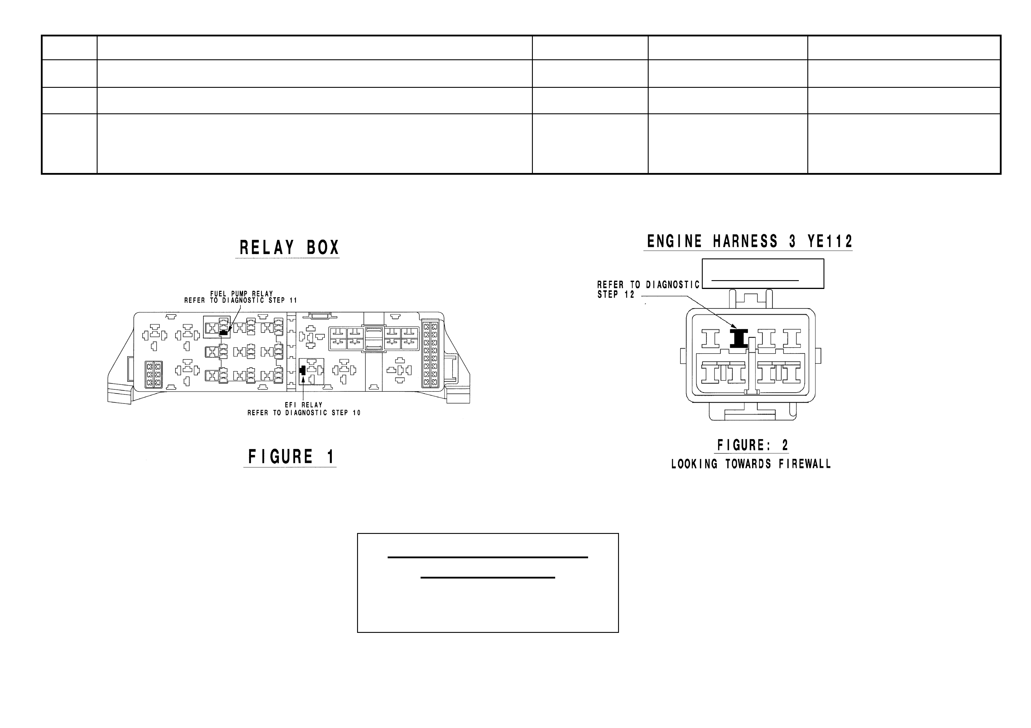
5 • Remove the EFI relay and back probe terminal 85 (as per figure 1 for VT.II / WH Vehicles or as per figure 3 for
VY / WK/ VZ Vehicles), with reference to Ground.
• With the Ignition switch to ON, measure DC voltag e .
_____________ volts DC.
6 • Remove Fuel Pump relay and back probe terminal 1 (as per figure 1 for VT.II / WH Vehicles) or terminal.2 (as
per figure 3 for VY / WK Vehicles), to measure continuity with ref. to Ground.
• Turn the ignition to ON, measure resistance.
_____________ Ohms.
7 • For VY / WK Vehicles Disconnect Engine Connector (X206 located above passe nge r k i ck panel ) and back pr obe
pin 9 (as per figure 4) with reference to ground.
• For VT.II / WH Vehicles Di s c on nect En gi n e Connector (YE112) and back probe pin (a s pe r fi g ure 2), wi t h
reference to Ground.
• For VZ vehicles Disconnect ECM connector A43 X1 and back probe pin 19 (as per figure 5) with reference to
ground.
• Turn the ignition to ON, measure DC voltage.
_____________ volts DC
8 • Is communications with Tech 2 active?
9 • With TDL flashing, operate “Unlock” button on the Remote Control.
• Does the TDL stop flashing?
Dealer Code: ISOVIN: Vehicle Build Date:
Km’s: ESS Pin No: BCM Part No: BCM Barcode No: .
This check sheet must signed by the Service Manager. ____________________________ Date: ____________
Fax the completed copy to Australian Arrow Customer Service. Facsimile: (03) 9775 0954.

HSV – EMBEDDED SECURITY SYSTEM (ESS) DIAGNOSTIC PROCEDURE (VT.II / WH / VY / WK / VZ).
STEP ACTION VALUE YES NO
1 • Turn ignition to ON position.
• Is one (1) beep audible?
• Go to Step 2 • Go to Step 3.
2 • Turn Ignition switch to the Start position.
• Does the vehicle start?
• System O.K, return
vehicle to customer.
• Go to Step 11.
3 • Are five (5) beeps audible? • Go to Step 13. • Go to Step 8.
4 • Turn Ignition switch to the Start position.
• Does the vehicle start?
• Go to Step 5. • Go to Step 6.
5 • Fill in the ESS check sheet and Contact Australian Arrow
Customer Service.
6 • Has there been a BCM replacement? • Go to Step 5. • Go to Step 14.
7 • Perform Serial Data Communications diagnostic as per Holden
Service Manual, then go to Step 5.
8 • Zero beeps were audible? • Go to Step 9. • Record number of beeps,
then go to Step 5.
9 • Turn Ignition switch to the Start position.
• Does the vehicle start?
• Go to Step 5. • Go to Step 10.
10 • Remove the EFI relay and back probe terminal 85 (as per figure.1
for VT.II / WH vehicle), or (as per figure.3 for VY/WK/VZ
vehicle), with reference to Ground.
• With the Ignition switch to ON, Is the value as specified?
• 12 volts DC. • Go to Step 5. • Refer to Service Manual
and check Ignition
system.
11 • Remove Fuel Pump relay and back probe terminal.1 (as per figure.1
for VT.II / WH vehicle), or (as per figure.3 terminal.2 for
VY/WK/VZ vehicle), to check continuity with reference to Ground.
• Turn the ignition to ON. Is the value as specified?
• Less than one
(1) Ohm.
• Go to Step 12. • Go to Step 5.
12 • For VT.II / WH vehicle, Disconnect Engine Connector (YE112)
and back probe pin (as per figure 2), with reference to Ground.
• For VY/WK vehicle, Disconnect Engine Connector (X206 located
above passenger kick panel), and back probe pin.9 (as per figure.4),
with reference to ground.
• For VZ vehicles Disconnect ECM connector A43 X1 and back
probe terminal 19 (as per figure 5) with reference to ground.
• Turn the ignition to ON. Is the value as specified?
• 12 volts DC • Go to Step 5. • Go to Step 5.
STEP ACTION VALUE YES NO
13 • Is the Theft Deterrent Led flashing? • Go to Step 4. • Go to Step 5.
14 • Is communications with Tech 2 active? • Go to Step 15. • Go to Step 7.
15 • With TDL flashing, operate “Unlock” button on the Remote Key.
• Does the TDL stop flashing?
• Go to Step 5. • Refer to Theft Deterrent
System diagnostics in
Holden Service Manual.
(Grey Connector)
Australian Arrow Pty. Ltd.
Customer Service.
Telephone: (03) 9785 0792
Facsimile: (03) 9775 0954
3. ELECTROCHROMI C MIRRORS
3.1 GENERAL
Electrochromic mirrors are a standard fitment to all VX Senator Signature & WH Grange vehicles. The mirror
features an electronically controlled mirror cell which changes colour in response to an applied electrical voltage.
This allows autom atic darkening of the mirror during night drivin g when the headl amps of a follo wing vehicle s hine
on an integr ated lig ht s ens or . This func tion on ly oper a tes when th e int egr a l sens o r detects lo w am bient ( i.e . a t nigh t
time). The mirror also incorporates two manually operated map lights - separately switched for passenger and
driver. ( Lig hts also i ll uminate in c onj unc t ion with inter io r lamp when activ ate d b y door s witc hes . T he mirr or operates
automatic ally however, an AUTO/MANU AL switch pro vides the driver with the option for the mirror to be d arkened
during l ow am bient light co nditions regardles s of pres ence or absence of follo wing head lamps . W hen rever se gear
is selected, the mirror automatically lightens.
3.2 SERVICE OPERATIONS
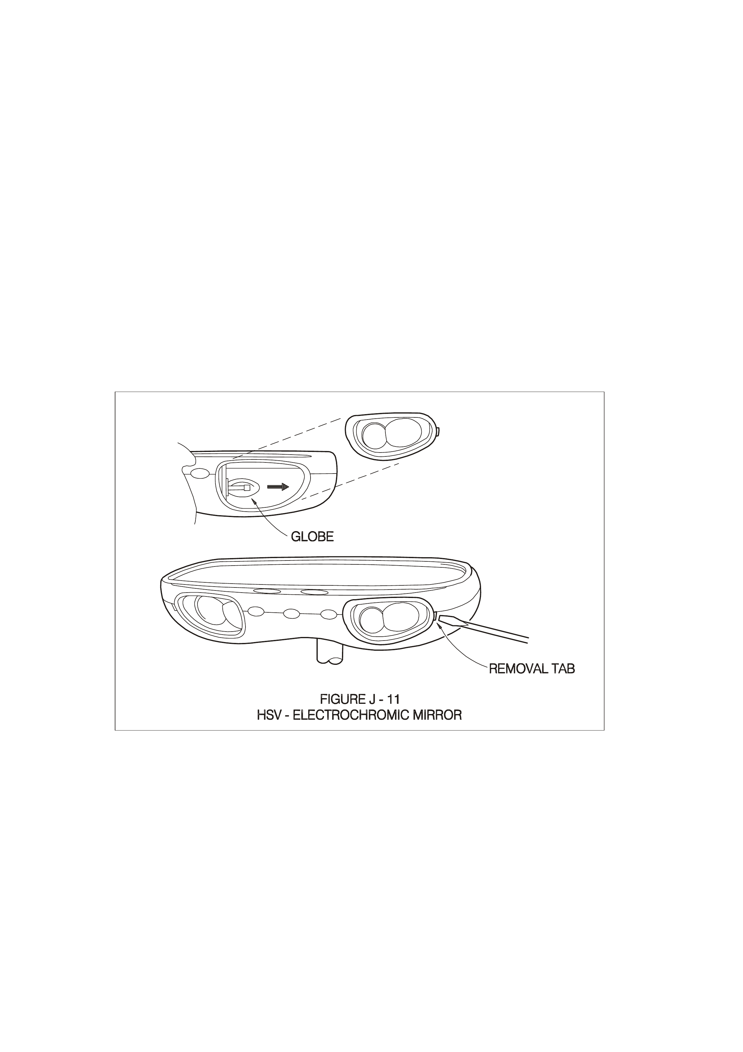
No specif ic s ervic ing of the m irror is requir ed. T o rep lac e m ap light globes us e a sm all s cr ew driver to pr ise o ut th e
lens
assembly to reveal a wedge-base five watt (5.0 W) globe (see Figure J-11). Refit lens assembly by inserting the
end closes t to centre of mirror f irst - ensure lam p bulb pass es through hol e in side of lens assem bly. The m irr or is
fitted with a sh ort h arness which c onnec ts t o the HSV el ectroc hrom ic m irror harness above the he adlin ing n ear th e
mirror: this harness runs across the headlining and down the `A’ Pillar to the main wiring harness which provides
connections to the battery, door switch, ignition, reverse lamps and ground.

4. HSV FOG LAM PS
4.1 GENERAL
HSV Fog lam ps are f itted directl y to the front f ascia of all HSV Coupe m odels. T he HSV lam ps use a glas s convex
reflector to provide a wid e- ang le b eam c oncentr ated i n a ran ge of 30 to 4 0 metr es in f r ont of the l amp. T he ex ternal
lense incorporates a clear horizontal section .
4.2 SERVICE OPERATION
No periodic servicing of the HSV lamps is required. Globes may be replaced by removing a water-tight access
cover on the rear of the lamp, unclip the two spring clips which retain the globe carrier at the focal point of the
reflector. Remove the globe and wire assembly from the seal, discard globe and replace with a new 12 Volt, 55
Watt H3 Globe assembly. Replacement fog lamps available through HSV are identified as follows
12C-000601 LAMP FOG
NOTE:
CONDENSATION MAY APPEAR ON THE LENSE OF THE FOG LAMP WHEN APPROPRIATE AMBIENT
CONDITIONS EXIST. THIS CONDENSATION WILL CLEAR AS THE AMBIENT CONDITIONS CHANGE OR
AFTER FOUR OR FIVE MINUTES OPERATION OF THE FOG LAMPS