
SECTION E - ENGINES
CAUTION:
HSV vehicles are equipped w ith a Supplemental Restraint System (SRS). An SRS consists of seat belt pre-
tensioners ( fit ted to all fron t seat s) , and a d riv er’s-sid e air bag or a driv er’s- side air b ag AND a passenger’s-
side air bag and left and right hand side air bags. Refer to CAUTIONS, Section 12M, of the Holden VX Series
Service Information before performing any service operation on or around SRS components, the steering
mechanism or wiring. Failure to follow the CAUTIONS could result in personal injury or unnecessary SRS
system repairs.
PURPOSE
The purpos e of this supplem ent is to provide infor mation on the various engine packages fitted to the HSV VX and
WH models. This information is designed to supplement that given in the Holden VX and WH Series Service
Inform ation, and details are given where dif ferenc es occ ur between the HSV m odels, and s tandard Holden m odels.
A series of ins tr uc tion drawings detail the des ign c hanges and indicate spec if ic part number s , fitting instruc tions and
relevant notes for vehicle servicing.
NOTE:
If specific technical data on a HSV model is not contained in this supplement, obtain data for that model from the
relevant Holden VX and WH Ser ies Ser vice Infor mation Supplement. Ref erenc es are made thr oughout this sec tion
to Holden Service Information, to assist in providing information for specific service operations.
CAUTION:
W hen hois ting (or j acking) HSV models, ens ure that the lifting head of the hoist lif ts on the chassis before the arm
of the hoist contacts the side-skirt
Techline
Techline

1. ENGINES - GENERAL INFORMATION
VX sees the carry over of the two Chevrolet Generation III engines introduced into the HSV range during VT2.
Thes e engines have both r ec eived upgrades to the bas e engine as manufac tur ed by GM, resulting in improvements
over the VT2 engine.
The 255 LS1 engine is not modif ied inter nally by HSV, and uses an HSV spec if ic c alibration to optimis e the benef its
of the specific HSV exhaust and inlet systems. As part of the development process, these changes have been
proven through extensive testing throughout Australia, as is the case with all engines fitted to HSV models.
The 300kW C4B engine is f itted with unique HSV com ponents, such as camshaf t, pistons, valve train and the lik e.
It should be noted however, that assembly procedures, torque settings, engine diagnosis, valve timing procedures
and other param eters are the sam e as f or the standard GMHA pr oduct unless s tated otherwise in this supplem ent.
The various HSV engines are discussed in the following paragraphs.
Engine Dress Covers The HSV LS1 V8 engine is fitted with a specific decorative engine cover. This is a large
one piece plas tic co ver that enc as es the fuel r ail and c oil pac k s , as well as the inlet manif old and thro ttle body. The
cover includes a moulded-in HSV Lion and Helmet logo, and is painted black, with silver highlights.
The HSV C4B LS1 V8 engine comes with specifically designed engine covers, that cover the two banks of the
engine, leaving the centre of the inlet manifold exposed. The covers are painted and moulded in a red
polypropylene copolymer, and incorporate HSV logos and 300kW signage.
HSV superchar ged V6 engines use the s tandard silver V6 S/C engine cover, but have a black 180 badge applied to
the leading edge of the cover.
LS1
06M-990601 COVER ASM: LS-1 ENGINE (SILVER HIGHLIGHT)
C4B LS1
06M-990701 COVER - ENGINE RH-GTS
06M-990702 COVER - ENGINE LH-GTS
V6 06M-971702 BADGE: "180" (ENGINE COVER)
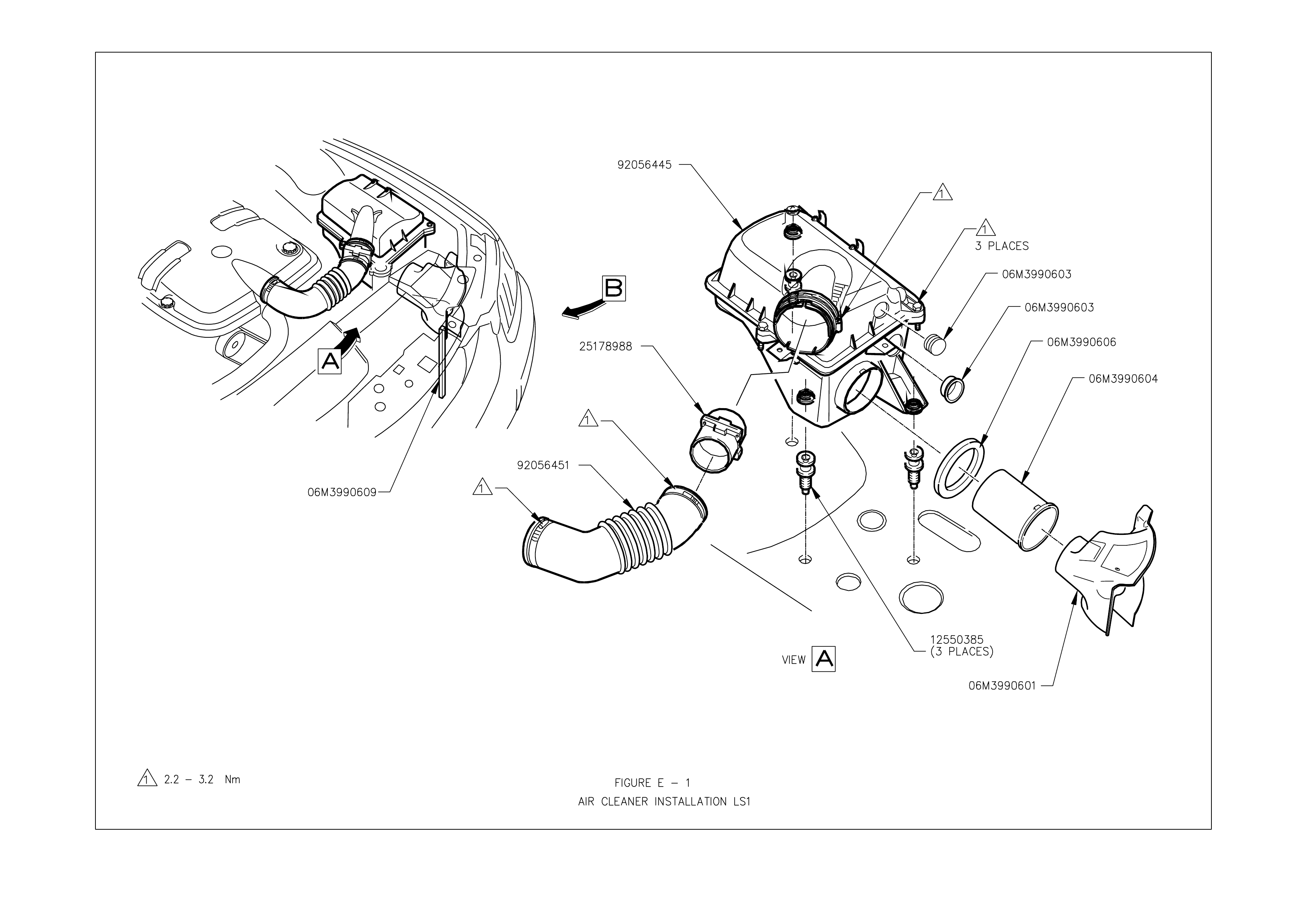
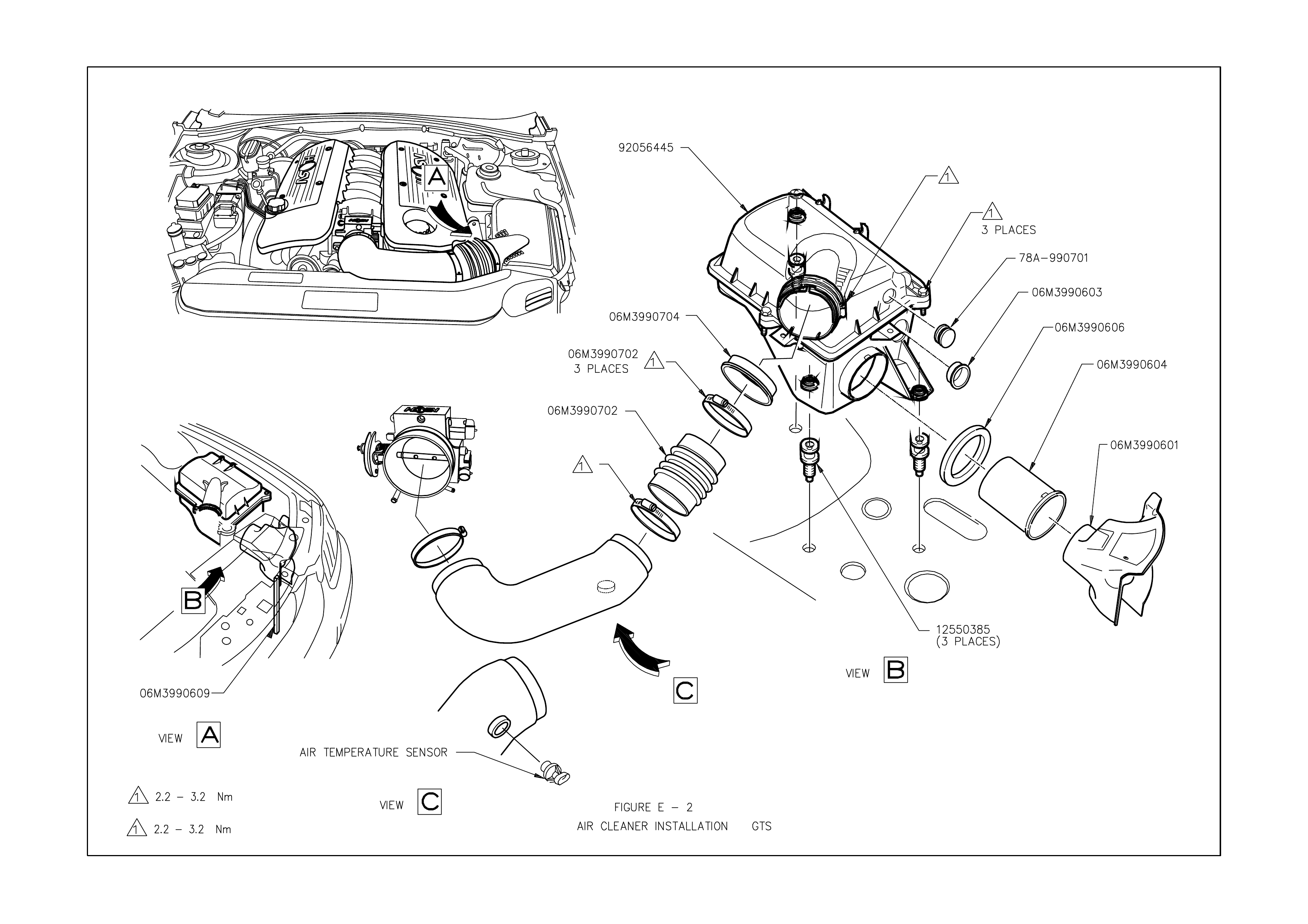
Engine Air Induction System The air induction system on the HSV C4B LS1 varies from the standard Holden
system, (and als o that used on the 255kW LS1) in that it does not use the original equipm ent Mass Air Flow (MAF)
Sensor. Instead, the engine r uns on a speed/density based calibration system , using a Manifold Absolute Pressure
(MAP) Sensor, Intake Air Temperature (IAT) Sensor and engine rpm to calculate the mass of air entering the
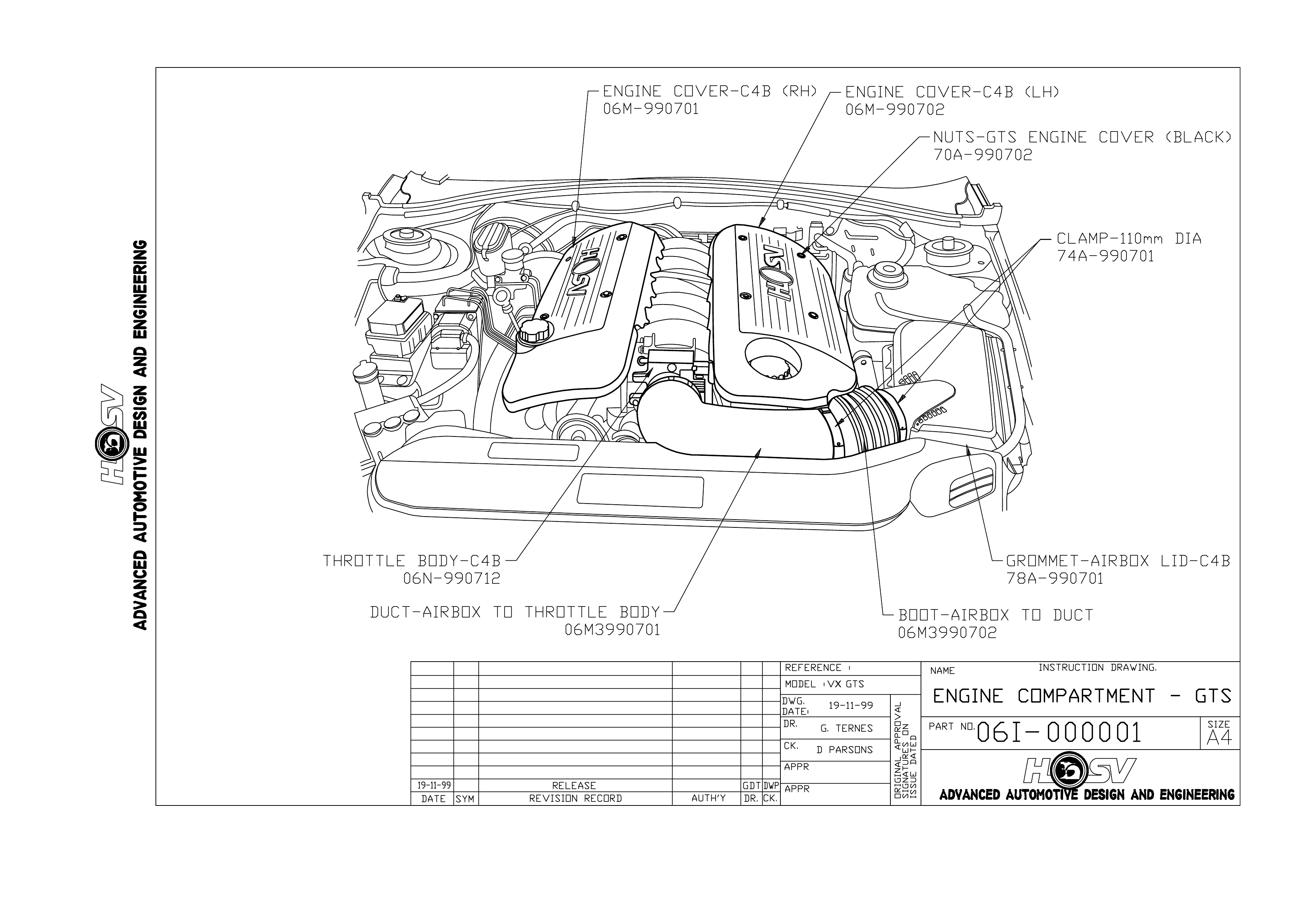
engine. Due to this change, the C4B engine uses a specific duct and boot combination from the airbox to the throttle
body. As part of these changes, the IAT sensor is relocated to the inlet duct, as this gives faster response to
changing intake air temperature changes.
The rest of the intake system is c omm on with the 255 LS1 introduced with VT2, and this incorpor ates much of the
standard Holden system, with the dif ference being concentrated on ensuring the engine receives as m uch cold air
as pos sible. This was found to give the greatest perf ormanc e advantage, and also helped reduce the perfor mance
lost due to stop start warm weather driving.
The intake system on the HSV LS1 uses the standard Holden air filter element, Mass Air Flow (MAF) Sensor and
Inlet Air Temperature (IAT) sensor. Service requirements for the filter are described in the Holden service
Information, and no adjustment is possible on the MAF sensor.
To rem ove the HSV inlet duct, it is necessar y to release the coolant system surge tank from its locating studs, then
pull the airbox base away from its locating studs, pulling the rear away first, and then away from the inlet duct. To
rem ove the duc t, it is bes t to take the outboard edge of the duc t and rotate it inboard and up to clear bodywork , then
pull out.
For replacement part numbers see figure E1, E2 and 06I-990701.
For information and diagrams of intake system for HSV V6 S/C models, see Section E of the HSV VT 2
Information.

Specific HSV Engine Components As the HSV C4B LS1 engine is a specific assembly for HSV, there are several
com ponents that warrant a s pecif ic m ention in this section. T hese com ponents are the specific valve springs, which
are of a constant diameter, and m ade from an oval formed wire, specific Titanium valve spring retainers to match
the springs, and a new, high lift camshaft. Details of this new camshaft are detailed in the table below:
HSV C4B CAMSHAFT SPECIFICATION
INTAKE EXHAUST
Lobe Lift 8.331mm (0.327”) 8.356mm (0.329”)
Duration at 1.27mm (0.050”) lift 184.7° 189.0°
Duration 278.8° 283.0°
Valve Timing at 1.27mm (0.050”)
lift
-Open
-Close
25.1° ATDC
29.8° ABDC
31.3° BBDC
22.3° BTDC

2. CLUBSPORT, R8, SENATOR AND GRANGE 255 LS1
2.1 GENERAL DESCRIPTION.
All HSV VX V8 m odels us e the new, Chevrolet developed LS1 engine. This engine is comm on with the Holden Gen
III V8 engine, and has a capacity of 5667m3, produced by a bore of 99.00mm and a stroke of 92.00 mm. The
compression ratio for this engine is 10.1:1.
The bas e engine design is that of a 90° V8, two valve per cylinder engine. The engine f eatures an alum inium block
and heads, with cast iron sleeves cast into the block during manufacture, while the heads have powdered metal
valve guides and seats pressed in place.
For more information regarding the LS1 engine, refer to Section 6A3 - ENGINE MECHANICAL - GEN III V8
ENGINE of the Holden's VX Service information.
The HSV LS1 engine does have an optim ised Cold air Induc tion System, a Low Restriction Exhaust System and an
Optimised Engine Management System. These improvements allow the engine to develop 250kW at 5,600 rpm and
475Nm at 4,400 rpm.

2.2 SERVICE OPERATIONS
The HSV LS1 engine fitted to ClubSport, Senator and Grange models is to be serviced in accordance with the
procedures detailed in the Holden VX Series service inform ation, refer to Section 6A3 - ENGINE MECHANICAL -
GEN III V8 ENGINE.
All HSV models however, are fitted with a specific HSV PCM to control the engine m anagement system. The PCM
contains a specific engine ( and in the case of autom atic vehicles, trans mission) c alibration, which can be identified
and serviced by the part numbers in the following chart. These PCMs contain a calibration that is available only
through HSV spare par ts, and cannot be re-program med by HSV or Holden Service T echnicians as is the case for
Holden calibrations.
12F 000603 PCM-VX 255 Manual (calibrated) 92105178
12F 000604 PCM-VX 255 Auto (calibrated) 92105180
12F 000704 PCM-VX 300 Manual (calibrated) 92105185
VX

3. GTS 300 C4B LS1
3.1 GENERAL DESCRIPTION.
The HSV G TS is the second tier engine to HSV. With a Holden production option designation of C4B, this engine is
based on the standard LS1 engine common with the 255kW models. The differences over the LS1 engine are
related to cylinder head and camshaft modifications.
The engine hardware was developed in conjunction with Callaway Cars in the USA, and the rest of the vehicle
development and validation carried out by HSV.
The changes included a specific camshaft, upgraded valve springs and titanium valve spring retainers, stainless
steel intake and exhaust valves, revised cylinder head porting and combustion chamber modifications, and a
specific, larger bore machined throttle body. The throttle body is the easiest identifier for the engine, as it is
anodised bright red. Additional marking is also evident on the cylinder heads, where the C4B designation is
machined into the head, on the exhaust port face.
The swept volume of the C4B LS1 engine is unchanged from the LS1 engine, although, due to the combustion
chamber modifications the compression ratio has been lowered slightly to 9.95:1. This gives improved engine
performance across the entire speed range, as it allows more spark advance, due to less knock sensitivity, to be
calibrated into the engine, particularly at low to medium engine speeds.
The HSV C4B LS1 engine uses a high flow induction system, that does not require a Mass Air Flow Meter, and
incorporates this with the optimised Cold air Induction System, a Low Restriction Exhaust System (including a
specif ic, str aight through design r ear m uf fler) and an Optim ised Engine Management System . Thes e impr ovem ents
allow the engine to develop 300kW at 6,000 rpm and 510 Nm at 4,800 rpm.
Techline

3.2 SERVICE OPERATIONS
The HSV C4B LS1 engine f itted to the VX GTS is to be s erviced in accordanc e with the procedur es detailed in the
VT Series II Service Information refer to Section 6A3 - ENGINE MECHANICAL - GEN III V8 ENGINE, however,
due to the deletion of the MAF sensor, the following service bulletin was released by HSV.
Dealer Bulletin - HSV GTS MAF Sensor Deletion
As part of the modifications made by HSV to achieve the 300kW output of the C4B engine, it was decided to use
the less res trict ive Speed/Density calibration system. T his allowed HSV to rem ove the Mas s Air F low (MAF) Sensor
from the intake system, removing the restriction it creates at high engine speeds advance requirements of the
engine by using a software model. This model incorporates inputs from the Manifold Absolute Pressure (MAP)
Sensor, along with the Inlet Air Temperature (IAT) Sensor and the engine rpm to predict airflow rate and volume
into the engine, and therefore fuelling requirements.
One eff ect of this system is that the engine no longer runs on 2 separate spark m aps, resulting in the potential for
some audible knock under certain conditions when using 91 Ron Unleaded. It should be noted that the engine still
runs an advanced knock control, and a level of detonation will not harm the engine.
When car rying out diagnostic work on the HSV VX G TS, it is im portant that you are aware that the PCM will always
log Diagnostic T rouble Code 0102-Mas s Air F low Sensor Circuit Low Fr equency. The calibration has been modified
to prevent the Malfunc tion Indicator Lamp f rom illum inating at this DTC the Ins trument will also log an f ault code in
this case DTC 19, which indicates that the instrument has detected a fault code in the PCM.
HSV GTS vehicles are also fitted with a PCM containing a specific engine calibration. This PCM is serviced in the
same manner as that for the HSV LS1 PCM.

3.3 ENGINE ASSEMBLY - SERVICE
Specific HSV components that have been included in the LS1 C4B 300 engine assembly are detailed below. The
part numbers for these components are listed for servicing requirements.
06Z-000701 ENGINE ASM-LS1 C4B AS SHIPPED
06X-990702 CAMSHAFT-C4B
06X-990703 VALVE SPRING-C4B
06X-990704 RETAINER-VALVE SPRING
06X-990705 SHIM-0.030"
06X-990706 SHIM-0.015"
06X-990707 VALVE-EXHAUST-C4B
06X-990708 VALVE-INLET-C4B
06A-990709 CYLINDER HEAD-MACHINED-C4B
06A-990710 CYLINDER HEAD ASM-C4B
06N-990712 THROTTLE BODY-C4B

4. SENATOR, XU6 AND WH GRANGE 180I S/C
4.1 GENERAL DESCRIPTION.
The XU6, Senator and Grange Supercharged V6 vehicles are fitted with a sequential fuel-injected Holden
Supercharged V6 engine assembly. A specific package of HSV designed components are fitted to the engine to
enhance engine performance. This package incorporates a Cold Air Induction system, Low Restriction Exhaust,
and an Optim is ed Engine Management System. These improvements allow the engine to develop 180 k W of power
at 5000 rpm and 380 Nm of torque at 3200 rpm.
The Cold Air Induction System consists of a HSV designed air cleaner box and a f ree-flow air duct. The assem bly
seals between the radiator support panel and hood. The Air Induction System uses the original Holden air filter
element.
The Supercharged V6 engined vehicles are f itted with a spec ific HSV ECM/PCM to carry out engine managem ent.
The ECM/PCM’s are fitted with specific MEM-CALs to suit the 180i engine package.

4.2 SERVICE OPERATIONS
The 180 engine package in the XU6, Senator and W H Grange, vehicles is to be serviced as specified in the VT
Series II Service Information, refer to Section 6A1 - ENGINE M ECHANICAL – SUPERCHARGED V6 ENGINE. In
addition, ECM/PCMs and MEM-CALS can be identified and serviced by the HSV part numbers in the following
chart.
Delco – part number Delco – broadcast code HSV Service
VX PCM 16269068 - 12F-000401
Memcal 16269078 DDRJ 12F-000402