SECTION I - ELECTRICAL AND INSTRUME NTS
CAUTION:
HSV vehicles are equipped with a Supplemental Restraint System (SRS). An SRS consists of seat belt pre-
tensioners ( fitted to all fr ont seats), and a d river ’s side ai r bag o r a driv er’s side ai rbag AND a pass eng er’s-
side air bag and left and right hand side air bags. Refer to CAUTIONS, Section 12M, of the Holden VX
Series Service Information before performing any service operation on or around SRS components, the
steering mechanism or wiring. Failure to follow the CAUTIONS could result in personal injury or
unnecessary SRS system repairs.
PURPOSE
The purpos e of this s upplem ent is to provide inf ormation on the H SV electric al and instr ument ac cessor ies fitted to
the HSV VX and WH models. The information is designed to supplement that given in the Holden VX Series
Service Inf ormation and de tails are given where d ifferences oc cur between the HSV m odels, and standard Hol den
models. A series of instruction drawings describe the design changes and indicate specific part numbers, fitting
instructions and relevant notes for vehicle servicing.
NOTE:
If specific technical data on a HSV model is not contained in this supplement, obtain data for that model from the
Holden VX Series or WH Series Service Information. References are made throughout this section to Holden
Service Information, to assist in providing information for specific service operations.
CAUTION:
W hen hoisting (or jac king) HSV models , ensure that the lifting h ead of the hoist lifts on the chass is before the arm
of the hoist contacts the side-skirt

INSTRUMENTATION
1. GENERAL.
A special Instrument Cluster designed by HSV is fitted to all HSV VX and WH vehicles. The cluster includes a HSV
speedom eter with a n op era t ing ra nge ex te nd ing t o 250 km/h. The c luster inc orporates a mid-gr e y face, red n eed les
and warning lights and, when illuminated, green numerals and letters.
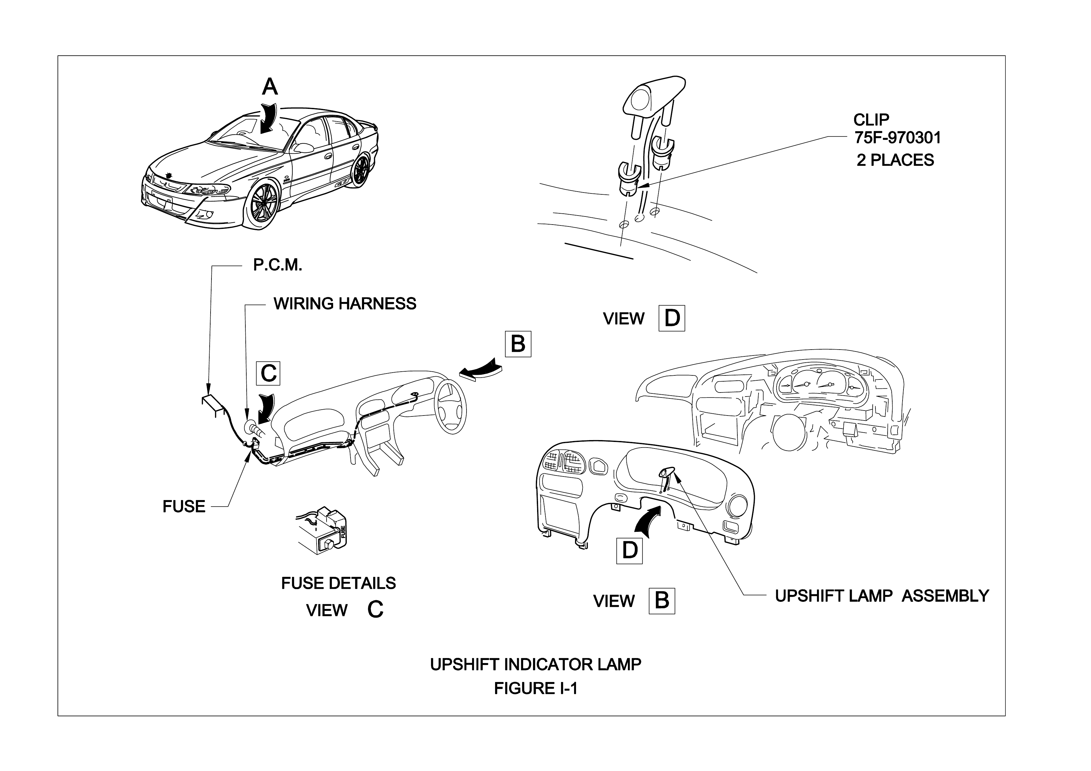
HSV GT S is fitted with an upshift ind icator. T his indic ator is c ontrolled b y the Engine Contro l Unit an d the LED and
buzzer giving the driver an indication when to upshift to achieve maximum performance. The shift indicator will
operate:
• When engine coolant is < 85°C at 4,000 RPM.
• When engine coolant is > 85°C:
− 1st 6,050 RPM
− 2nd 6,200 RPM
− 3rd 6,300 RPM
− 4th 6,300 RPM
− 5th 6,300 RPM
The harness has an inline fuse (3A) which is located underneath the glove compartment near the firewall. The
power feed for the indicator is fused by F12, turn signal (15A). Ref. Figure I-1
In VX models the tachometer redline is designed to suit particular engine specifications - refer table below.
Engine Tachometer Red Line
S/C XU6 5,500 rpm
LS1 Auto & Manu al 6,000 rpm
GTS 6,500 rpm

2. SERVICE OPERATIONS.
The HSV instrument cluster and the standard Holden VX cluster use the same mounting fixtures and fasteners.
Remove, s ervice and r efit the HSV instr ument cluster in ac cordance with the pr ocedures det ailed in the VX Series
Service Information, refer to Section 12C - Instruments, Wipers/Washers & Horn.

ELECTRICAL FACILITIES
The various special HSV options fitted to the VX and W H range of vehicles often require that special or additional
electric harnesses be installed. Some of these HSV harnesses are fitted during vehicle build-up at the Holden
factor y and other sm aller har nesses (of ten called ‘a patc h harness ’) are f itted at t he HSV f acilit y when the elec trical
option is being ins talled. A summar y of thes e electric al harness es is inclu ded to fac ilitate servic e, repair an d retro-
fitment of the HSV options.
PART No DESCRIPTION
12H2970801 Level Ride Patc h Har ness (f itted to all Sen ators )
12H-990302 Sunroof Harness
12H-970801 Electrochromatic Mirror harness (fitted to all Senator Signatures)
12H2970202 Level Rid e Patc h (No n Sen ators )
92095260 ClubSport & XU6 Main Wiring Harness with ESS
92078336 Senator, Senator Si gna ture , Senator Si gn ature Es tat e Mai n Wiring Harness with ES S
92083500 Grange Main Wiring Harness with ESS
92085497 Grange Roof Lamp Harness
92100737 Senator Signat ur e Body Control Module
92080633 Grange Body Control Module
12L-9916 07 ESS (Em bedde d Sec urity System )
12H-000701 Harness Shift Indicator
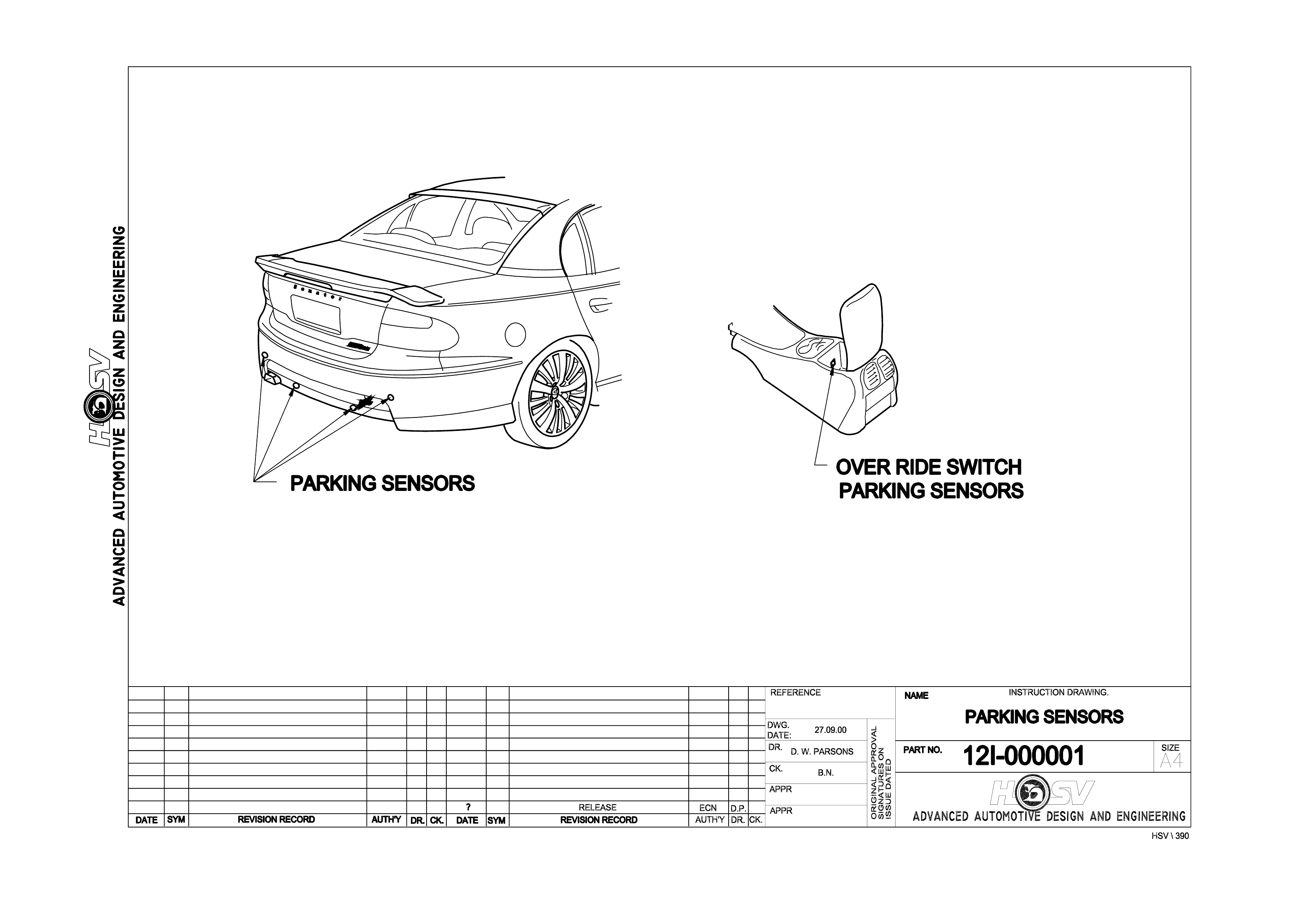
PARKING SENSORS
The HSV Park ing sensor s ys tem as sists the driver wh ile reversing i nto a park ing space by warnin g of obstacles at
the rear of the vehicle. Please remember that there is no substitute for driver care while reversing. The
responsibility for recognising and assessing obstacles remains with the driver. Reversing safely can only
be achieved by adopting a responsible driving style. A prompt warning is only possible if the vehicle is
reversed slowly.
The parking sensor system switches on automatically when the ignition is on and reverse gear is selected . This is
indicated by a single, brief tone when reverse is selected. An obstacle is recognised from approximately 120 cm
between t he obs tacle a nd the r ear bumper . If this dist ance is r educed the f reque nc y of warn ing ton es will inc rease.
The tone will rep eat f aster and f aster until it b ecom es a contin uous tone a t wh ich poi nt the dist ance t o the ob stacle
will be less than 30 cm.
An overri de s witch has b ee n provid ed to s witch of f the s ystem to avoid f alse a larm ing when a tr ailer or b icyc le rack
is attached to the vehicle. The override switch is located in the centre console.
PARKING SENSOR SYSTEM DIAGNOSTICS
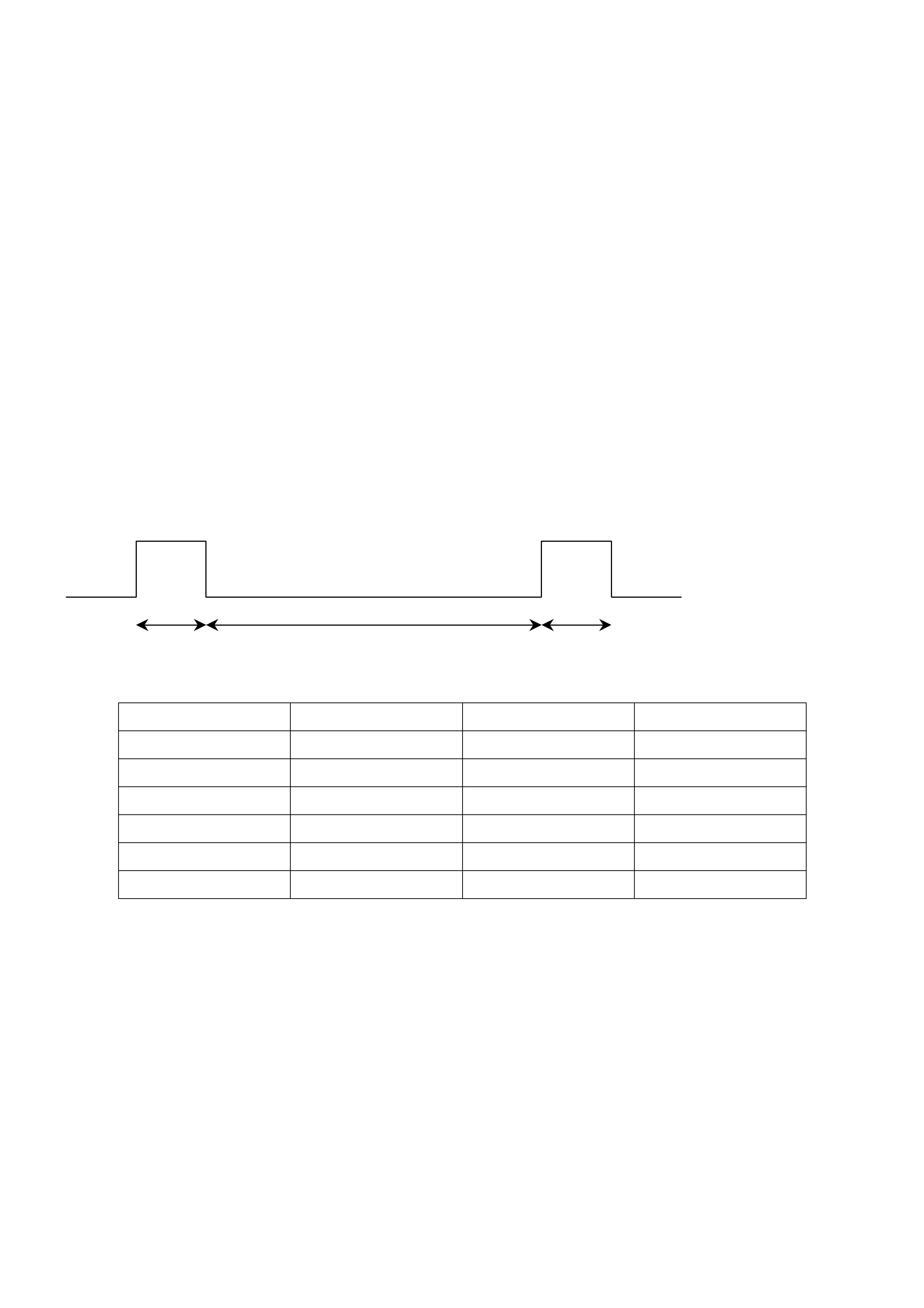
Normal Operation
In norm al operation, with no obstacles within two m etres of the rear of the vehicle, the parking sensor will issue a
single short tone (0.5 sec) when reverse gear is first selected with ignition on. If there are obstacles behind the
vehicle then the audible will be a series of beeps or a continuous tone dependant on distance to object. Refer to
table 1.
Tone on Tone off duration depending on distance to obstacle Tone on
75 ms 75 ms
Obstacle Distance Tone frequency Tone On Tone Off
30 cm 1200 Hz Continuous
40 cm 1200 Hz 75 ms 75 ms
60 cm 1200 Hz 75 ms 150 ms
80 cm 1200 Hz 75 ms 225 ms
100 cm 1200 Hz 75 ms 300 ms
120 cm 1200 Hz No tone
Table 1
Fault Diagnosis
1. No Tone At Switch On
If no tone is heard when reverse gear selected with ignition on, check park sensor override switch located in the
centre console. If changing switch position does not result in switch on tone, check operation of reverse lights –
parking sensor is powered from the reverse lamp circuit. If park lamps OK, then check condition of park sensor
harness connection at right hand tail lamp connector. The red lead connects to the reverse lamp circuit (for 12V
into park sensor module) and the brown lead connects to the lamps ground circuit.
2. Short High Tone Followed By Continuous Low Tone
W hen reverse gear is selec ted with ignition on, a shor t high to ne ma y be heard f ollowed b y a contin uous low tone .
This indicates that the park sensor system self diagnosis has detected a problem. Switch off the ignition and
remove the system coding plug from its socket to enter s ystem diagnostics. T he system coding plug is located on
the park sensor wiring har ness between the left hand tail lam p and the park sensor module. The plug is sim ilar in
appearance to an automotive fuse but contains a resistor. Do not replace this plug with a fuse.
It will also be necessary to remove the right kick panel below the dash. The park sensor speaker assembly is
installed behind this panel. The speaker assembly also contains a visual indicator that will be required during the
system diagnosis.
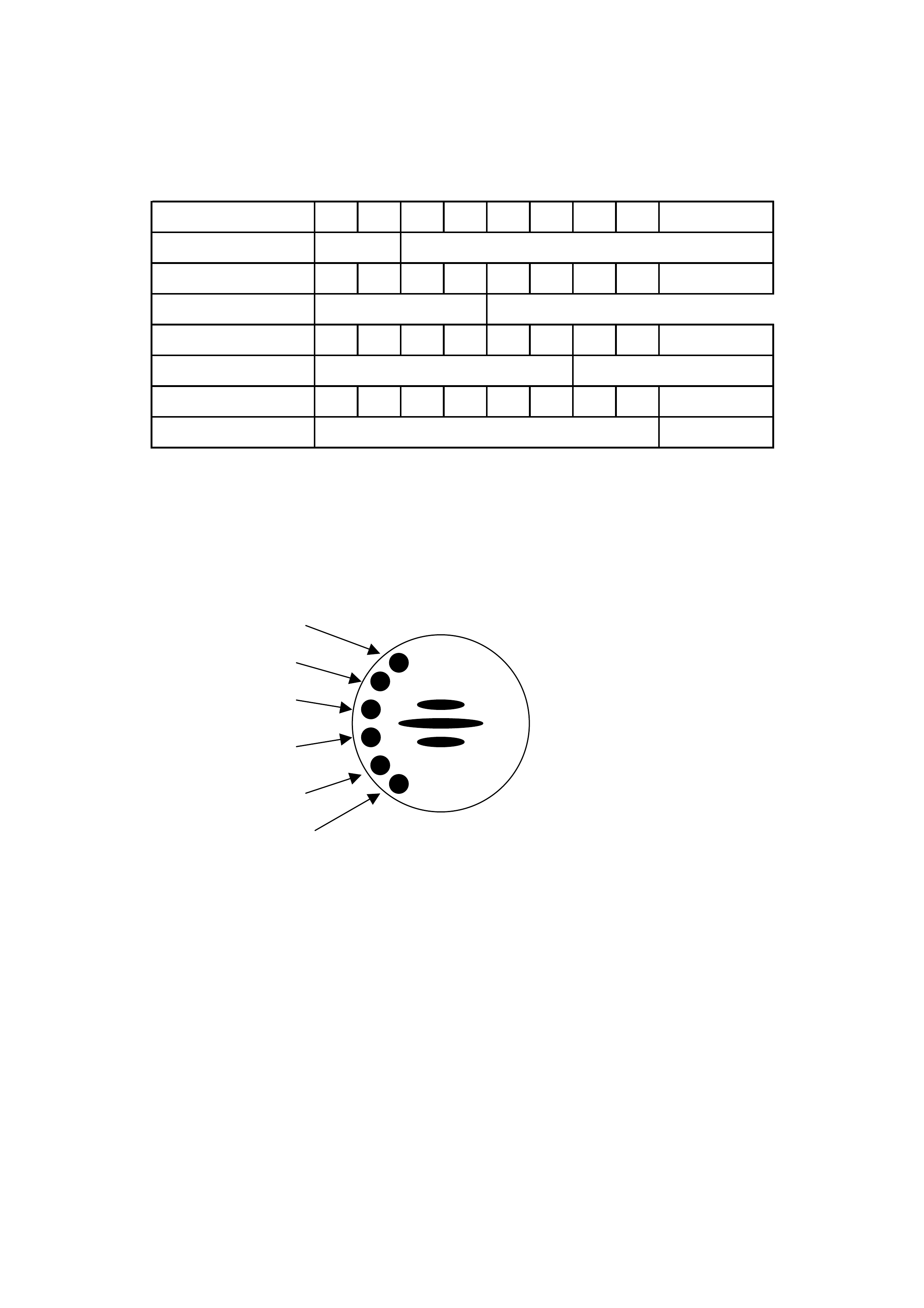
NB. It is essential to have at least two m etres of clear space behind the vehicle while in dia gnostic mode to avoid
any interference from detected objects. Switch the ignition on again (with reverse gear selected). If there is a
defectiv e sensor, it will be indicat ed as shown in the table be low. Sensor 1 is located on the right han d side of the
vehicle and sensor 4 on the left.
Fault Sensor 1 •¢¨
LED 1 On
Fault Sensor 2 •¢•¢¨
Fault Sensor 3 •¢•¢•¢¨
LED 3 Of
f
Fault Sensor 4 •¢•¢•¢•¢¨
LED 4 Of
f
LED 4 On
LED 1 Of
f
LED 2 Of
f
LED 2 On
LED 3 On
• Tone on, 600 Hz for 1 second
¢ Tone off for 1 second
¨ Sequence end, 2 seconds
If several sensors are faulty, the error codes on the individual sensors are displayed in turn separated by the 2
second ending sequence. A faulty plug or wiring harness will also be indicated as a sensor fault.
If no sensor is faulty, the low warning tone will be cycled for 3 seconds on and 3 seconds off to indicate that the
coding plug has been removed.
If there is a fault with the Control Unit, the error display will be as follows:
Opening sequence low warning tone (600 Hz) and two red LEDs followed by 1 second off
Error sequence low warning tone (600 Hz) and two yellow LEDs
This indicates a fault in the control unit hardware, power supply (reverse lamp voltage) sensor voltage or coding
plug short circuit.
LED 1 red
LED 2 red
LED 3 yellow
LED 4 yellow
LED 5 green
LED 6 green