
SECTION J - OPTIONS AND ACCESSORIES
CAUTION:
HSV vehicles are equipped with a Supplemental Restraint System (SRS). An SRS consists of seat belt pre-
tensioners (fitted to all front seats), and a driver’s-side air bag or a driver’s-side air bag AND a passenger’s-
side air bag and left and right side air bags. Refer to CAUTIONS, Section 12M, of the Holden VX Series
Service Information before performing any service operation on or around SRS components, the steering
mechanism or wiring. Failure to follow the CAUTIONS could result in personal injury or unnecessary SRS
system repairs .
PURPOSE
The purpose of this sup plement is to provide inform ation on the special options and accessories fitted t o the HSV
VX and WH models. This information is designed to supplement that contained in the Holden VX and WH Series
Service Inf ormation, and d etails are given where dif ferences oc cur between the HSV m odels and standard Holden
models. A series of instruction drawings detail the design changes and indicate specific part numbers, fitting
instructions and relevant notes for vehicle servicing.
NOTE:
If specific technical data on a HSV model is not contained in this supplement, obtain data for that model from the
relevant Holden VX Series and WH Series Service Information. References are made throughout this section to
Holden Service Information, to assist in providing information for specific service operations.
CAUTION:
W hen hoisting (or jac king) HSV models , ensure that the lifting h ead of the hoist lifts on the chass is before the arm
of the hoist contacts the side-skirt

1. HSV SUNROOF
1.1 GENERAL
The HSV specific Sunroof is available as an opt ion on all HSV VX and W H models. The Sunroof is a tinted glass,
electrically operated, two-way sliding and tilting type, equipped with an internal sliding blind and front edge wind
deflector. The Sunroof is operated by a rocker type switch (which is back-lit) centrally located in the vehicle's
headlini ng in fr ont of the S unroof vent a perture . Sunroof s are equ ipped wit h a Sunroof Control U nit which provi des
several pre-programmed functions and the facility to programme an additional option.
The pre-programme d functions are:
• Soft touch
By a single touch of the switch the roof can be fully opened to the maximum tilt position or the
maximum slide position.
• Variable tilt position
The pane l c an be c los ed f r om tilt in f our st e ps by cont i nuously pres s ing the s witc h and re le as in g i n th e
desired posi tion
• Jamming protection (Safety Feature)
When closing the sunroof by soft touch or by autoclose, the sunroof automatically opens when it
encounters an obstacle. The roof will continue to try to close until the obstacle is removed.
• Autoclose function
Three seconds after switching off the ignition the sunroof will close automatically. This can be
prevented by pressing the switch once within 3 seconds after the ignition is switched off.
• One - way closing
This feature always closes the panel from above, assuring a flush fit of the panel.
The optional programmable function is:
• Comfort position in the sliding range
With this feature you will be able to program a preset stopping position of the panel in the sliding range
of the sunroof. The panel will stop at the preset position when opened via the soft touch operation.

1.2. OPERAT ION
Panel movement into the venting and sliding positions is controlled by:
Continuous control (pressing the switch longer than 0.3 seconds):
• Full control over the panel movement in slide position
• Releasing the switch will stop the panel movement
• A full stop in maximum slide and closed position.
Four steps down tilt adjustment (pressing the switch longer than 0.3 seconds):
• W hen closing the sunro of from m inimum tilt pos ition by press ing the switch c ontinuous ly, the panel
will stop briefly in four intermediate positions.
• Releasing the switch will stop the panel movement.
• To continue the stepped operation, press the switch again.
One touch contro l (pressing and releasing the switch within 0.3 seconds):
• Automatic panel movement towards full open or full closed position (slide and tilt).
• Anti-jamming protection while closing.
• The panel movement can be interrupted by pressing the switch.
Auto-close:
• When the ignition is switched off, the roof will close after a 3-second delay.
• Anti-jamming protection while closing.
• Pressing the switch within 3 seconds after the ignition switch off will cancel Auto-close.
• Closing the roof is still possible after Auto-close has been active.
• Auto-close will not be activated if any other function is active.
SPECIAL FUNCTIONS
Programming me mory position
• Any position in the sliding range of the panel can be programmed as a “comfort position”.
• The panel will stop at that position when opened by One touch control.
One way closing
• To ensure perfect positioning of the panel after closing, the panel will always close from above
(even when closed from a slide position).
Interior trim -
Sunshade
Sunshade operation depends on panel movement as below:
• Moving the gl ass pane l to ti lt pos it ion , the s uns ha de au tomatic ally opens to a vent position a nd can
be moved to full open position by hand.
• Moving th e g lass pa nel in to s lid e positi on, t he s u ns had e will move t oge ther and can also be f ur ther
opened by hand.
• Closing the sunshade always has to be done manually. The sunshade can only be closed
completely when the glass panel is in closed position.
Wind deflector
The wind defector automatically comes up when the panel moves into sliding positions and goes
down when the panel closes again.


2. FIRE EXTINGUISHER
2.1 GENERAL.
HSV VX models are fitted with a HSV design fire extinguisher. The extinguisher is located in the rear luggage
compartment.

2.2 SERVICE OPERATIONS
The fire extinguisher should be subjected to a regular visual inspection in accordance with the instructions on the
extinguis her. Par tic ularl y, the extin guisher should be ins pected f or dam age and to ensure tha t the integr al pr essur e
gauge registers the appropriate internal pressure. When discharged or when the internal pressure is outside the
prescribed limits, the extinguishers should be serviced and re-charged by an appropriate supplier. New
extinguishers are available through the HSV spare parts systems.

3. HSV SPECIFIC BODY CONTROL MODULES.
3.1 GENERAL
HSV specific Body Control Modules (BCM’s) are stand ard on VX Senator Signature and WH Grange Models . The
modules have the same physical dimensions and connections as the standard BCM’s but have different software
which is specific to HSV. Both the VX Senator Signature and WH Grange models have their own specific module.

3.2 CHANGING BCM’S
• If the BCM is cha n g ed R efer to H SV Embedded Security System, Section 4.2 or Section 4 .3 in the Holden
Special Vehicles Service Information Supplement.
• If extra or new keys are required Refer to HSV Embedded Security System, Section 4.4 in the Holden
Special Vehicles Service Information Supplement.

4. HSV EMBEDDED SECURITY SYSTEM VX AND WH.
4.1 GENERAL
The new HSV Embedded Security System (ESS) is fitted as standard equipment to all HSV VX and WH models.
The ESS is a micro-processor controlled immobiliser which automatically interrupts essential electrical circuits
when in “armed mode”. The ESS stores the BCM’s security code and when the car is started it reads this code from
the SCI bus . If th is c ode is dif f erent from the s tored on e the ESS en ters ar med mode and pre ven ts the vehicle f rom
starting.

4.2 LINKING THE ESS TO A NEW BCM AT THE CAR DEALER –
BCM IN WARRANTY
If the BCM requires replac ement within the BCM warrant y period, the Dealer shall be supplied with a replacement
BCM and two new keys, all programm ed with the same BCM security code as the original BCM. In this case, the
replacement BCM and new keys are simply fitted to the vehicle. No ESS specific requirements are needed.

4.3 LINKING THE ESS TO A NEW BCM AT THE CAR DEALER –
BCM OUT OF WARRANTY
W hen a BCM requ ires r epl acement outs ide th e BC M war ranty period the D ea ler shall need to obtain a re pla c em ent
BCM and keys from Holden’s Service Parts Operation (HSPO). The replacement BCM and Keys will not contain
the same BCM Security Code as the original BCM.
When a new BCM with different BCM security code is fitted to the vehicle, the dealer will have to do the following:
- Link the BCM and PCM.
- Program a new key to the BCM.
TECH 2 m ust be connected to the vehicle diagnos tic connector whilst the k ey is being program med and/or ES S is
being link ed to the vehicl e. The Link Enable Proce dure is requir ed to be perf ormed twice to allo w an all new key to
be programmed and also allow the ESS learn to learn the BCM security code. The procedure for programming a
new key to a new BCM and linking the ESS to the vehicle is as follows:
1. Fit new BCM to the vehicle.
2. Ensure driver's door is closed, driver's door is unlocked, and wash-wipe switch is off.
3. Place new key into the ignition barrel.
4. Turn ignition on. Verify ESS beeps 5 times.
5. TECH2 must be operating in the “Normal Mode” submenu of the Body Control Module sub-menu.
6. Perform the Link Enable Procedure (s ee Section 4.5) . W ait 1 s econd between each loc k unlock to ensure the
door lock actuators function correctly during this procedure.
7. Verify that the ESS beeps twice. TECH2 reports ignition is at 12Vdc. The ESS has now entered “Key
Programming mode”.
8. Select Key Programming function – “All New Key” - from the security sub-menu in the body menu of the
TECH2. Enter BCM security code as requested by TECH2. Complete key programming as requested by
TECH2.
9. Turn ignition off and wait for 2 seconds. Turn ignition on.
10. Verify ESS beeps 5 times. (At this stage the ESS is in “armed mode”).
11. TECH2 must be operating in the “Normal Mode” submenu of the Body Control Module sub-menu.
12. Perform the Link Enable Procedure (s ee Section 4.5). W ait 1 s econd between each loc k unlock to ensure the
door lock actuators function correctly during this procedure.
13. Verify that the ESS beeps twice. TECH2 reports ignition is at 12Vdc.
14. Link the PCM to the BCM using TECH2. ESS beeps twice (ESS has now learned the BCM security code).
15. Turn ignition off. Wait until TECH2 programming is complete.
16. Turn ignition on.
17. Turn ignition off. Wait 2 seconds.
18. Turn ignition on.
19. Verify ESS beeps once. The ESS is now operating in “normal mode”.
20. Crank engine. Verify vehicle starts as normal.

4.4 KEY P ROGRAMMING MODE
Once the ESS has been placed into key programming mode the ESS will behave as if in “sleep mode” for one
ignition c ycle only. This allows for the one ignition c yc le that is requ ired to progra m a new key to a new or ex isting
BCM. The ESS will enter “norm al mode” for the next ignit ion cycle. If the BCM is a new BCM in the vehicle with a
new security code, the ESS will then enter “armed mode” as expected.
4.4.1 PROGRAMMING EXTRA KEYS TO THE VEHICLE.
Programming more keys for the vehicle can be achieved using TECH2 once the ESS has been re-linked to the
vehicle as described as follows:
1. Ensure driver's door is closed, driver's door is unlocked, and wash-wipe switch is off.
2. Place new key into the ignition barrel.
3. Turn ignition on. Verify ESS beeps 5 times.
4. TECH2 must be operating in the “Normal Mode” submenu of the Body Control Module sub-menu.
5. Perform the Link Enable Procedure (s ee Section 4.5) . W ait 1 s econd between each loc k unlock to ensure the
door lock actuators function correctly during this procedure.
6. Verify that the ESS beeps twice. TECH2 reports ignition is at 12Vdc. The ESS has now entered “Key
Programming mode”.
7. Selec t Ke y Programm ing functio n – “Ex tra Ke y” - fr om the sec urity sub-m enu in the bod y menu of the T ECH2.
W hen TECH2 reques ts igni tion to b e c ycled with th e existing key, lea ve the new key in th e igniti on bar rel a nd
instead, press the unlock button on th e existing key. Verif y the ESS beeps once and th e Thef t Deterrent L ED
stops flashing. Complete key programming as requested by TECH2.
8. Turn ignition off and wait for 2 seconds.
9. Turn ignition on. Verify ESS beeps once. The ESS is now operating in “normal mode”.
10. Crank engine. Verify vehicle starts as normal.
4.4.2 PROGRAMMING ALL NEW KEY
Programming an All New Key for the vehicle can be achieved by performing the following procedure:
1. Ensure driver's door is closed, driver's door is unlocked, and wash-wipe switch is off.
2. Place new key into the ignition barrel.
3. Turn ignition on. Verify ESS beeps 5 times.
4. TECH2 must be operating in the “Normal Mode” submenu of the Body Control Module sub-menu.
5. Perform the Link Enable Procedure (s ee Section 4.5). W ait 1 second bet ween each lock unlock to ens ure the
door lock actuators function correctly during this procedure.
6. Verify that the ESS beeps twice. TECH2 reports ignition is at 12Vdc. The ESS has now entered “Key
Programming mode”.
7. Select Key Programming function – “All New Key” - from the security sub-menu in the body menu of the
TECH2. Enter BCM security code as requested by TECH2. Complete key programming as requested by
TECH2.
8. Turn ignition off and wait for 2 seconds.
9. Turn ignition on. Verify ESS beeps once and T heft Deterrent LED is off. The ESS is now operating in “nor mal
mode”.
10. Crank engine. Verify vehicle starts as normal.

4.5 LINK ENABLE PROCEDURE
Each ESS has it’s own unique Link Enable Code (LEC), programmed into each ESS by HSV. This code
corresponds to a unique sequence of 10 vehicle body functions comprising of the following actions:
1. Drivers door. Open then Close
2. Drivers door. Lock then Unlock
3. Wash-Wipe. On then off.
Approximately 60,000 link enable codes are available. (Pull stalk towards steering wheel and release).
For the Link Enable Procedure contact:
A ustralian Arrow Pty Ltd Customer Service quoting ESS PIN.
Telephone: (03) 9785 0792
Facsimile: (03) 9775 0954

4.6 SERVICE OPERATIONS
In the event of a suspected ESS failure the following diagnostic procedure must be followed:
HSV – EMBEDDED SECURITY SYSTEM (ESS) CHECK SHEET.
in the event of a suspected ESS failure, fill in the following check sheet.
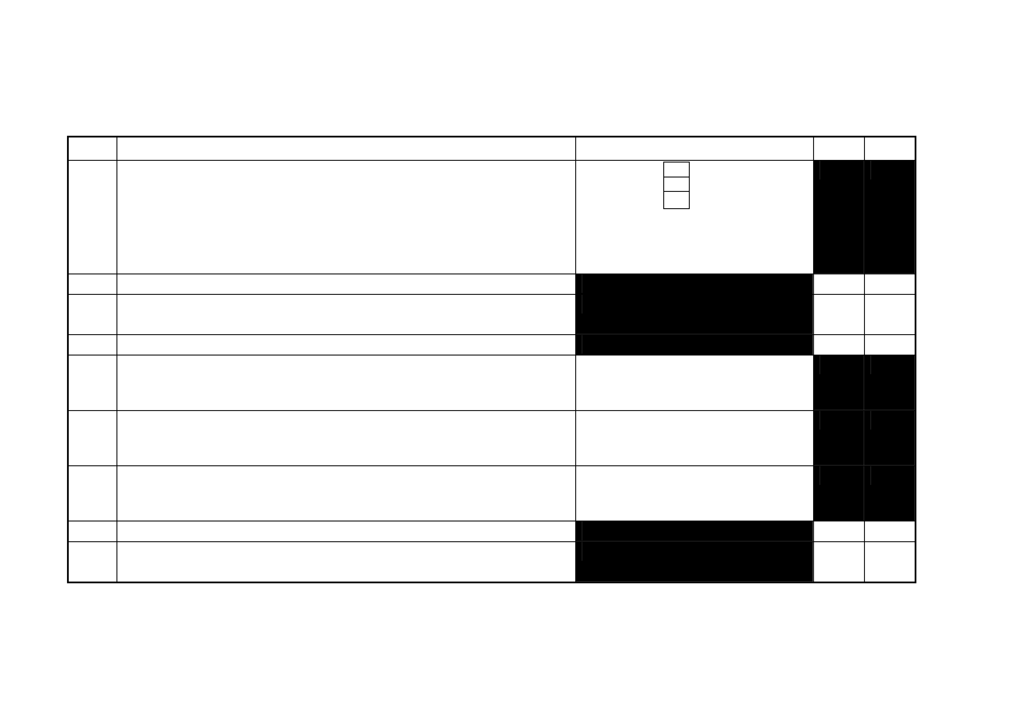
STEP ACTION MEASURED VALUE YES NO
1 • Turn ignition to ON position and listen for the number of beeps. Zero beeps:
One beep:
Five beeps:
Other:_________
2 • W ith the ignition in the ON position, is the Theft Deterrent Led f lashing?
3 • Turn Ignition switch to the Start position.
• Does the vehicle start?
4 • Has there been a BCM replacement?
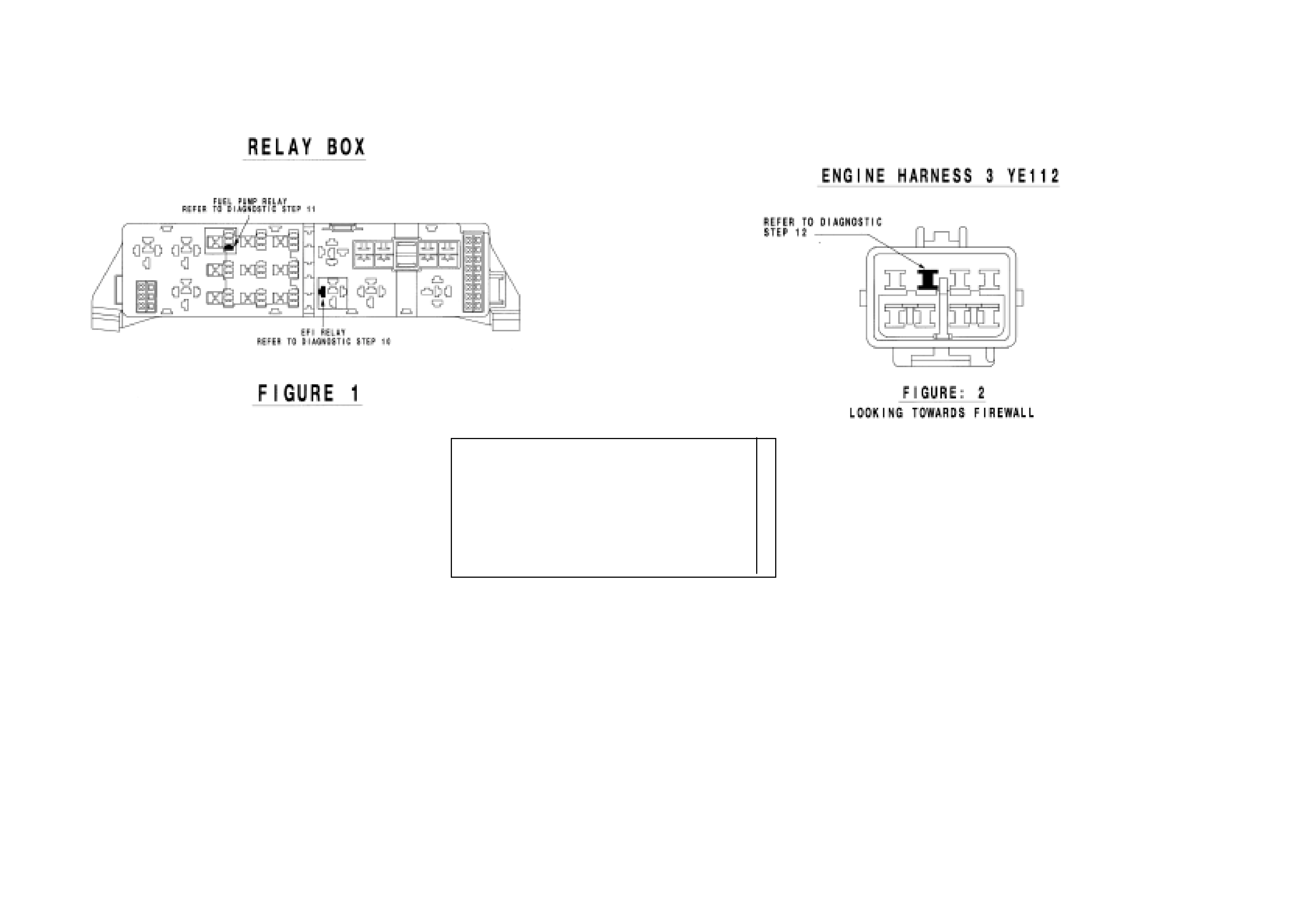
5 • Remove the EFI relay and back probe terminal 85 (as per figure 1), with
reference to Ground.
• With the Ignition switch to ON, measure DC voltage.
_____________ volts DC.
6 • Remove Fuel Pump relay and back probe terminal 1 (as per figure 1), to
measure continuity with reference to Ground.
• Turn the ignition to ON, measure resistance.
_____________ Ohms.
7 • Disconnect Engine Connector (YE112) and back probe pin (as per figure
2), with reference to Ground.
• Turn the ignition to ON, measure DC voltage.
_____________ volts DC
8 • Is communications with Tech 2 active?
9 • W ith TDL flashing, operate “Unlock” button on the Remote Control.
• Does the TDL stop flashing?
This check sheet must signed by the Service M anager. ____________________________ Date: ____________
Fax the completed copy to Australian Arrow Customer Service. Facsimile: (03) 9775 0954.

HSV – EMBEDDED SECURITY SYSTEM (ESS) DIAGNOSTIC PROCEDURE.
STEP ACTION VALUE YES NO
1 • Turn ignition to ON position.
• Is one (1) beep audible? • Go to Step 2 • Go to Step 3.
2 • Turn Ignition switch to the Start position.
• Does the vehicle start? • System O.K, return
vehicle to customer. • Go to Step 11.
3 • Are five (5) beeps audible? • Go to Step 13. • Go to Step 8.
4 • Turn Ignition switch to the Start position.
• Does the vehicle start? • Go to Step 5. • Go to Step 6.
5 • Contact Australian Arrow Customer Service.
6 • Has there been a BCM replacement? • Go to Step 5. • Go to Step 14.
7 • Perform Serial Data Communications diagnostic as per Holden Service
Manual, then go to Step 5.
8 • Zero beeps were audible? • Go to Step 9. • Record number of
beeps, then go to
Step 5.
9 • Turn Ignition switch to the Start position.
• Does the vehicle start? • Go to Step 5. • Go to Step 10.
10 • Remove the EFI relay and back probe terminal 85 (as per figure 1), with
reference to Ground.
• With the Ignition switch to ON, Is the value as specified?
• 12 volts DC. • Go to Step 5. • Refer to Service
Manual and check
Ignition system.
11 • Remove Fuel Pump relay and back probe terminal 1 (as per figure 1), with
reference to Ground.
• Turn the ignition to ON. Is the value as specified?
• Less than one (1)
Ohm. • Go to Step 12. • Go to Step 5.
12 • Disconnect Engine Connector (YE112) and back probe pin (as per figure 2), with
reference to Ground.
• Is the value as specified?
• 12 volts DC • Go to Step 5. • Go to Step 5.
13 • Is the Theft Deterrent Led flashing? • Go to Step 4. • Go to Step 5.
14 • Is the communications with Tech 2 active? • Go to Step 15. • Go to Step 7.
15 • With TDL flas hing, operate “Unlock” button on the Remote Control.
• Does the TDL top flashing? • Go to 5. • Refer to Theft
Deterrent System
diagnostics in
Holden Service
Manual.
Australian Arrow Pt y Ltd.
Customer Service.
Telephone: (03) 9785 0792
Facsimile: (03) 9775 0954

5. ELECTROCHROMIC MIRRORS
5.1 GENERAL
Electrochromic mirrors are a standard fitment to all VX Senator Signature & Estate, & WH Grange vehicles. The
mirror features an electronically controlled mirror cell which changes colour in response to an applied electrical
voltage. This allows automatic darkening of the mirror during night driving when the headlamps of a following
vehicle shine on an integrated light sensor. This function only operates when the integral sensor detects low
ambient ( i.e. at n ig ht time). The m irror als o incor porates two m anual l y operat ed m ap li ghts - s epar ate ly switc hed f or
passenger an d dri ver. (Ligh ts als o illum inate in c onjunc tion with i nterior lam p when activated by door s witches . T he
mirror operates automatic ally however, an AU TO/MANUAL s witch provides the dr iver with the optio n for the m irror
to be darkened during low ambient light conditions regardless of presence or absence of following headlamps.
When reverse gear is selected, the mirror automatically lightens.
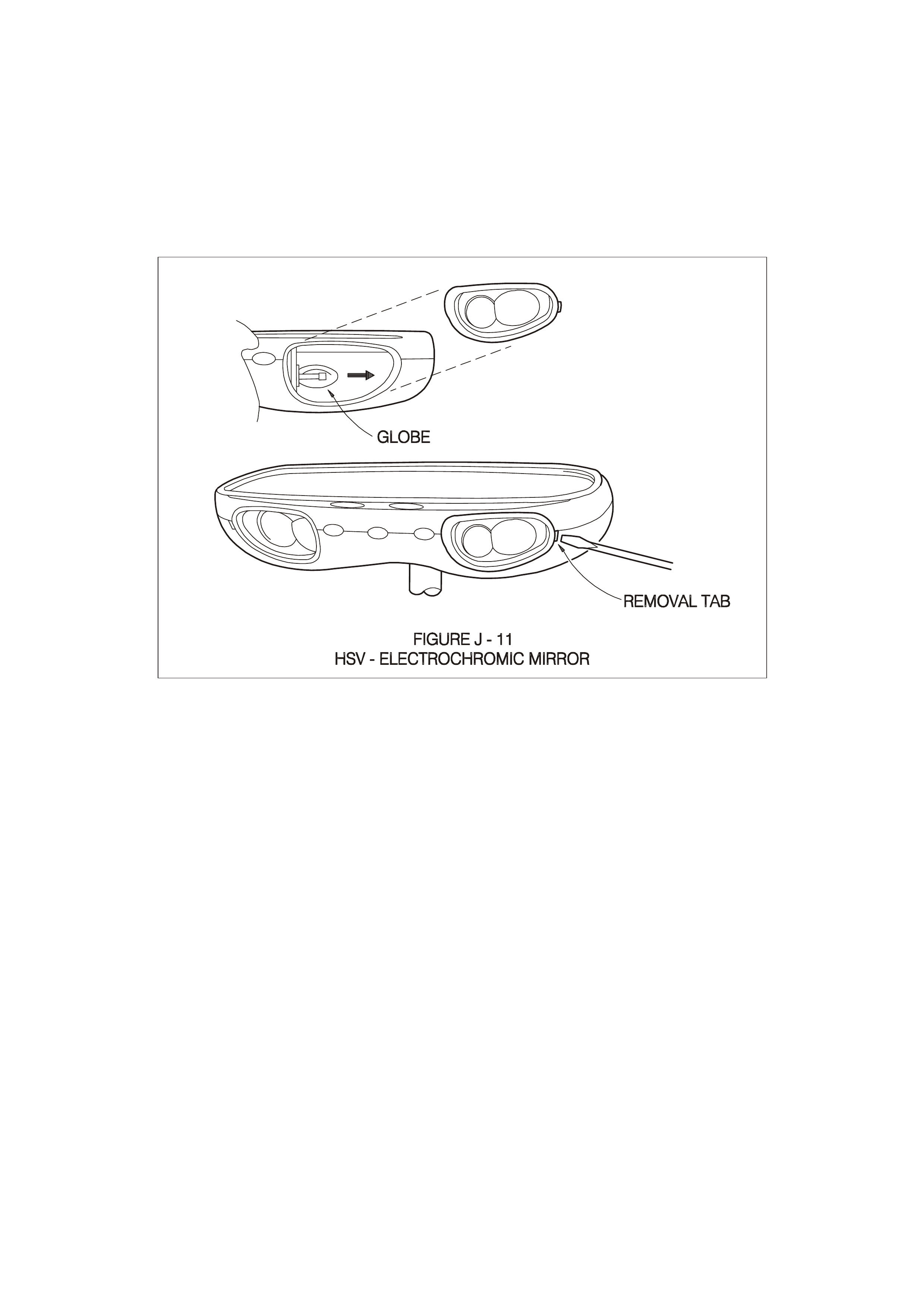
5.2 SERVICE OPERATIONS
No specif ic s ervic ing of the m irror is requir ed. T o rep lac e m ap light globes use a s m all scr ew driv er to pr ise out th e
lens assem bly to reveal a wedge-base five watt (5.0 W) globe (see Figure J-11). Refit lens assembly by inserting
the end c los est to centr e of mirr or f ir st - ens ure l amp bulb pas ses t hr ou gh ho le in s ide of le ns as sembl y. The mirror
is fitted with a short harness which connects to the HSV electrochromic mirror harness above the headlining near
the mirror: this harness runs across the headlining and down the `A’ Pillar to the main wiring harness which
provides connections to the battery, door switch, ignition, reverse lamps and ground.

6. HSV FOG LAMPS
6.1 GENERAL
HSV Fog lamps are fitted directly to the front fascia of all HSV VX models. The HSV lamps use a glass convex
reflector to pro vi de a wid e- ang le b eam conc entrated i n a r an ge of 30 t o 40 metr es in f r ont of the l amp. The e x ternal
lens incorporates a clear horizontal section .

6.2 SERVICE OPERATION
No periodic servicing of the HSV lamps is required. Globes may be replaced by removing a water-tight access
cover on the rear of the lamp, unclip the two spring clips which retain the globe carrier at the focal point of the
reflector. Remove the globe and wire assembly from the seal, discard globe and replace with a new 12 Volt, 55
Watt H3 Globe assembly.
Replacement fog lamps available through HSV are identified as follows
12C-1000601 LAMP FOG
NOTE:
Condensation may appear on the lens of the fog lamp when appropriate ambient conditions exist. This
condensation will clear as the ambient conditions change or after four or five minutes operation of the fog lamps