
SECTION J - OPTIONS AND ACCESSORIES
CAUTION:
HSV vehicles are equipped with a Supplemental Restraint System (SRS). An SRS consists of seat belt
pre-tensioners (fitted to all front seats), and a driver’s-side air bag or a driver’s-side air bag AND a
passenger’s-side air bag and left and right side air bags. Refer to CAUTIONS, Section 12M, of the
Holden VS Series Service Information or Section 12M, of the VT Series II Service Information before
performing any service operation on or around SRS components, the steering mechanism or wiring.
Failure to follow the CAUTIONS could result in personal injury or unnecessary SRS syste m repairs.
PURPOSE
The purpose of this supplement is to pro vide inform ation on the special options and accessories fitted to the HSV
VT2, VS & WH m odels . T his inf ormation is des i gne d to s upp lement th at c ont ai ned in the Hol de n VT Ser ies II, VS &
WH Series Service Information, and details are given where differences occur between the HSV models and
standard Holden models. A series of instruction drawings detail the design changes and indicate specific part
numbers, fitting instructions and relevant notes for vehicle servicing.
NOTE: If specific technical data on a HSV model is not contained in this supplement, obtain data for that model
from the relevant VS Series Service Information, VT Series II Service Information or the WH Series Service
Information. References are made throughout this section to Holden Service Information to assist in providing
information for specific service operations.
CAUTION: When hoisting (or jacking) HSV models, ensure that the lifting head of the hoist lifts on the chassis
before the arm of the hoist contacts the side-skirt.

1. HSV SUNROOF
1.1 GENERAL
The HSV specific Sunroof is available as an option on all HSV VT2, VS & WH models. The Sunroof is a tinted
glass, electrically operated, two-way sliding and tilting type, equipped with an internal sliding blind and front edge
wind def lector. T he Sunroof is operated b y a roc ker type s witch ( which is b ack-lit) centrally locat ed in the vehicle's
headlini ng in fr ont of the S unroof vent aperture. Sunroof s are equip ped wit h a Sunroof Control Unit whic h provides
several pre-programmed functions and the facility to program an additional option.
The pre-programmed functions are:
• Soft touch
By a single touch of the switch the roof can be fully opened to the maximum tilt position or
the maximum slide position.
• Variable tilt position
The panel can be closed from tilt in four steps by continuously pressing the switch and
releas ing in the desir e d pos iti on
• Jamming protection (Safety Feature)
When closing the sunroof by soft touch or by autoclose, the sunroof automatically opens when
it encounters an obstacle. The roof will continue to try to close until the obstacle is removed.
• Autoclose function
Three seconds after switching off the ignition the sunroof will close automatically. This can be
prevented by pressing the switch once within 3 seconds after the ignition is switched off.
• One - way closing
This feature always closes the panel from above, assuring a flush fit of the panel.
The optional programmable function is:
• Comfort position in the sliding range
With this feature you will be able to program a preset stopping position of the panel in the
sliding range of the sunroof. The panel will stop at the preset position when opened via the
soft touch operation.

2.2 OPERATION
Panel movement into the venting and sliding positions is controlled by:
Continuous control (pressing the switch longer than 0.3 seconds):
• Full control over the panel movement in slide position
• Releasing the switch will stop the panel movement
• A full stop in maximum slide and closed position.
Four steps down tilt adjustment (pressing the switch longer than 0.3 seconds):
• When closing the sunroof from minimum tilt position by pressing the switch continuously,
the panel will stop briefly in four intermediate positions.
• Releasing the switch will stop the panel movement.
• To continue the stepped operation, press the switch again.
One touch contro l (pressing and releasing the switch within 0.3 seconds):
• Automatic panel movement towards full open or full closed position (slide and tilt).
• Anti-jamming protection while closing.
• The panel movement can be interrupted by pressing the switch.
Auto-close:
• When the ignition is switched off, the roof will close after a 3-second delay.
• Anti-jamming protection while closing.
• Pressing the switc h with in 3 s econds after the ignit ion switch off will cancel Auto-close.
• Closing the roof is still possible after Auto-close has been active.
• Auto-close will not be activated if any other function is active.
Special Functions
Programming memory position
• Any position in the sliding range of the panel can be programmed as a “comfort position”.
• The panel will stop at that position when opened by One touch control.
One way closing
• To ensure perfect positioning of the panel after closing, the panel will always close from
above (even when closed from a slide position).
Interior Trim -
Sunshade - Sunshade operation depends on panel movement as below:
• Moving the glass panel to tilt position, the sunshade automatically opens to a vent position and can be
moved to full open position by hand.
• Moving the glass panel into slide position, the sunshade will move together and can also be further
opened by hand.
• Closing the sunshade always has to be done manually. The sunshade can only be closed completely
when the glass panel is in closed position.
Wind deflector - The wind defector automatically comes up when the panel moves into sliding positions and
goes down when the panel closes again.

2.3 SERVICE OPERATIONS
NOTE: Dealers are to contact Hollandia Su nroofs directly by telephone on (02)9 540-4811 before carrying out an y
service operation on the Sunroof.
Several Fault Diagnosis Charts are included in this section. These charts list Possible Causes and Solutions and
provide a reference to a particular paragraph to resolve the fault. Some recommended solutions refer to the
Installat ion Ma nua l a nd t he r e le va nt ex tr acts f r om that manual are inc lu ded at t he r e ar of this s ec ti on. A lso i nc lud ed
in this section is Figure J-1 which shows an exploded view of the sunroof construction.
FAILURES
Repair advice for mechanical failures
REPAIR ADVICE FOR MECHANICAL FAILURES
PROBLEM POSSIBLE CAUSE SOLUTION
While cycling the panel from tilt
to close it begins sl idi ng
rearward
Blocking catch is broken Replace blocking catch, see
2.6.10
While cycling fully open panel
forward, it begins tilting under
roofskin
Blocking catch is broken Replace blocking catch, see
2.6.10
Panel is misaligned side to side Timing of drive cables incorrect Retime drive cables, see 2.6.5
Panel sliding too slowly (with
13.5V power supply panel
should not take more than 7 sec.
to cycle from full retraction to
closure)
Weak battery
Misaligned panel creating drag
or friction
Weak motor. Test as indicated in
2.5.4
Dirty mechanism
Charge or replace
Retime drive cables, see 2.6.5
Replace motor, see 2.6.1
Clean and grease mechanism or
replace if necessary, see 2.6.9
Glass panel stopping
prematurely Sunroof control unit adjusted
improperly
Obstacle in mechanism or guide
track
Synchronise sunroof control unit,
see 2.6.3
Find object and remove
Sunshade fails to open when
glass panel is opened to tilt
position.
Retraction mechanism broken Replace retraction mechanism,
see 2.6.8.
Repair Advice for Rattling Noises
REPAIR ADVICE FOR RATTLING NOISES
PROBLEM POSSIBLE CAUSE SOLUTION
Drainchannel rattles Inspect for insulator tape
between drai nc han nel and
mechanism
Add insulat or tape
Steel panel ventilation tray
rattling Curvature of front ventilation tray
incorrect
Insufficient contact between rail
and ventilation tray tumbling
mechanism
Wi res insufficiently secured
Correct curvature, manual
adjustment
Correct rear side ventilation tray
to improve rail contact
Secure wires
Rattling in motor area Cover plate on motor has loose
screws Tighten coverplate screws
Repair advice for wind noises
REPAIR ADVICE FOR WIND NOISES
PROBLEM POSSIBLE CAUSE SOLUTION
Panel closed, excessive
windnoise Glass panel seal not tight to
trimring
Blocking catch broken
Correct glass panel adjustment,
see 2.6.11 or installation manual
5.3
Replace blocking catch, see
2.6.10
Panel ve nte d em itting wh is tling
sound Vinyl headliner material wrapped
around sunshade too thin,
creating large wind channel
between rail and side of
sunshade
Place insulating tape along
either outboard edge of
sunshade to close channel.
See installation manual 4.1.5
Steel panel vented emitting
whistling sound Vinyl headliner material wrapped
around trimtray too thin, creating
large wind channel between rail
and side of trimtray
Place insulating tape along
either outboard edge of trimtray
to close channel. See installation
manual 4.1.5
Repair advice for water leaks
REPAIR ADVICE FOR LEAKAGE PROBLEMS
PROBLEM POSSIBLE CAUSE SOLUTION
Water coming through panel
opening area Blocked draintubes
Misaligned or kinked draintubes
Housing frame distorted,seal to
rail disc on nec ted
Rear rail bracket has broken
seal
Inspect draintubes clean
opening, blo w out tubes
Correct routing of draintubes.
See installation manual 3.2
Correct frame curvature if
necessary reseal rail to frame
Reseal at rear rail seal point, see
2.6.9
Headliner wet in front Either frame seam has incorrect
seal Reseal at seam
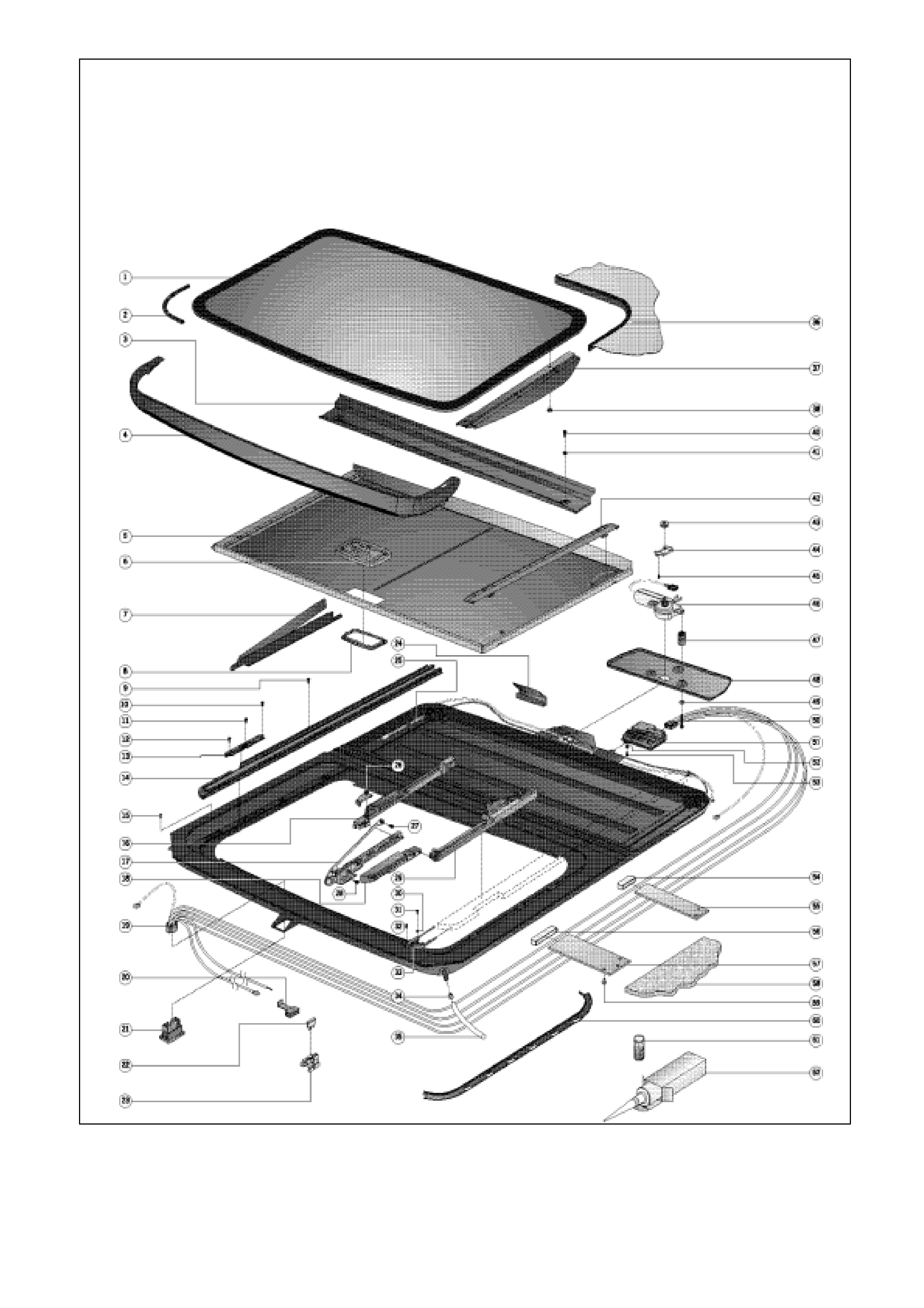
FIGURE J-1 - HSV SUNROOF - EXPLODED VIEW
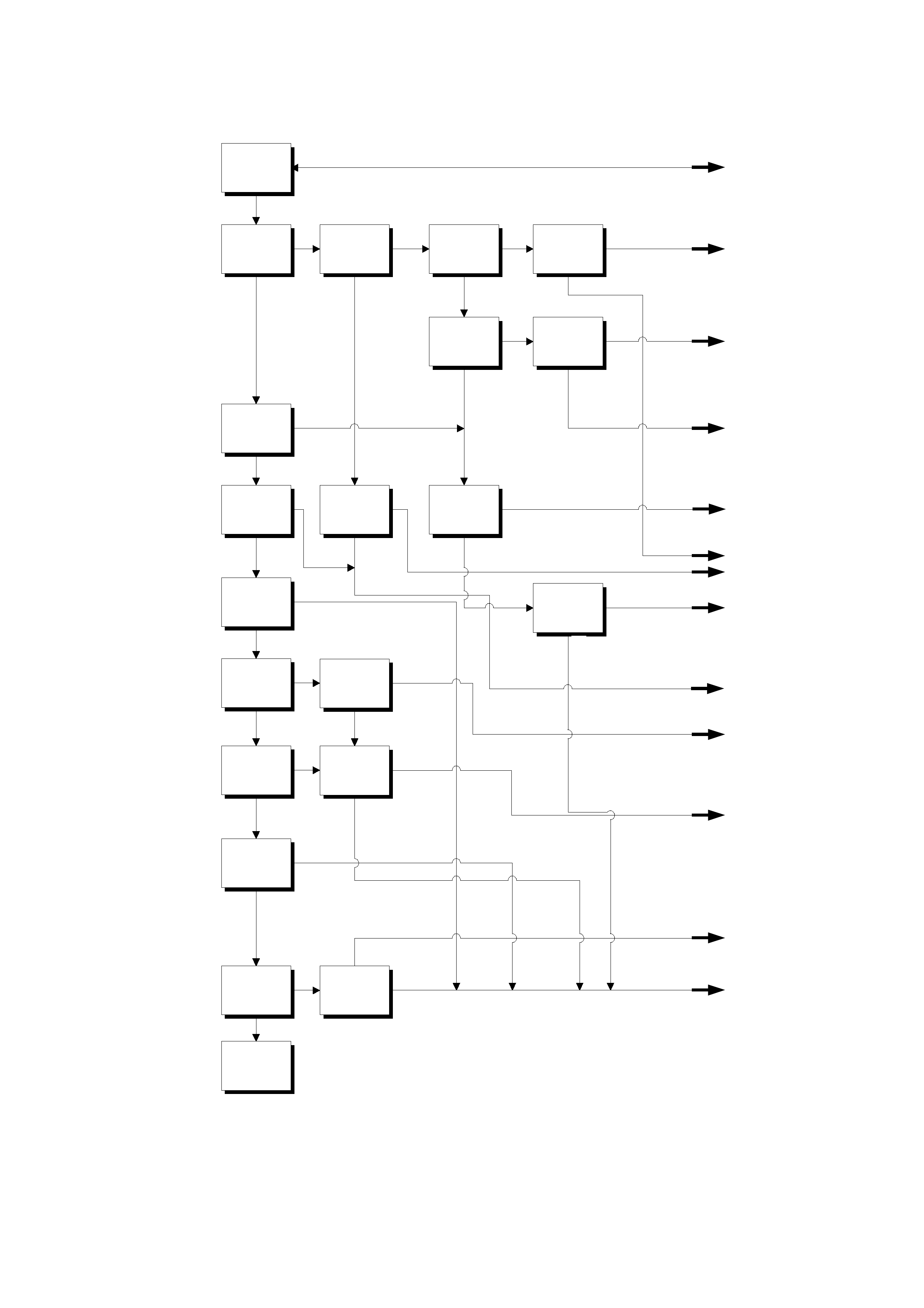
ELECTRICAL TROUBLE SHOOTING TABLE
Page 1 of 2
Panel moves
wh en h olding
switch pressed
Test TVS
(ignit ion on)
Does SCU make
a click sound
SCU, red an d
green wires
combined
measure 12 V?
SCU pow erline
measures 12 V
when body
grounded
Red/black
pow erline
12 V w he n body
grounded
In b o th
directions
Tilting and
sliding possible
He ffe n en
schuiven
mogelijk
M ot o r ru n n ing
properly
Soft touch
operating
possible?
Is the auto close
function working
Is the comfort
position
working?
One way closing
working?
Sw itch
O.K.?
(chapter 2.2.3.)
Fuse10 A
O.K.?
(chapter 2.2.1.)
Wire harness
O.K.?
Motor stops,
SCU clicks in
max. slide and
max tilt position?
TVS
O.K.
In one direction
only
Power over red /
black wire w hen
ignitio n is
switched off
Po w er over
red wire when
ignition is
switched off
no no no no
yesyesyes
yes
yes
yes
yes
yes
yes
no no
no
no
yes
nee
no
yes
yes
no
yes
no
yes
no
no
yes
yes
no
yes
no
yes
no
no
no
yes
Power over red /
black wire w hen
ignitio n is
switched off
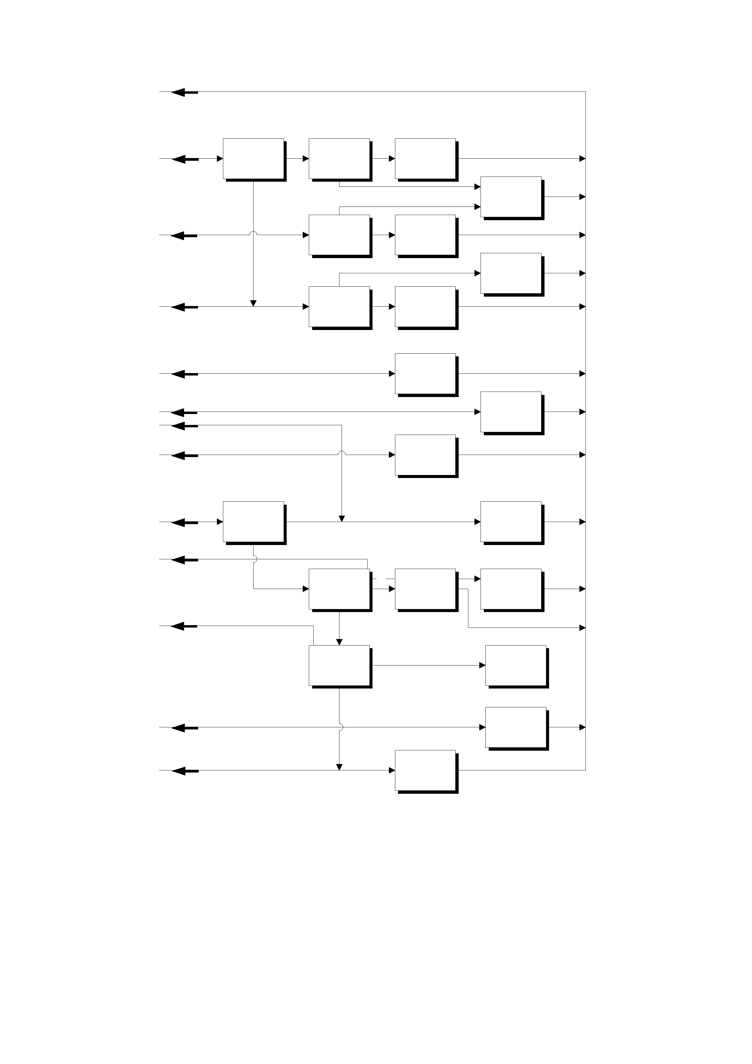
Page 2 of 2
Fuse 20 A
O.K.?
(chapter 2.2.1.)
fuse 20 A
replaced? Replac e
fuse 20 A
Fuse 10 A
replaced Replace fuse
10 A
Wire harness
O.K.?
(chapter 2.2.2.)
Improve
powerline
connections
Replace switch
Replace wire
harness
Manual override
crank operation
functioning?
Motor
O.K.?
(chapter. 2.2.4.)
Replace motor
(chapter. 3.1.)
ReplaceSunroof
Control Unit
(chapter 3.2.)
Synchronize
Sunroof Control
Unit
(chapter. 3.3.)
Inspect and
correct wire
shortage
Replace wire
harness
Improve ground
wire connection
Solve mechnical
failure
(chapter. 1.1.)
Improve
connection red /
black
wire
no
yes
yes
no
y
es
no
yes
no
yes
no
yes
Improve
connection red
wire
Sufficient power
over red wire
when operating
the switch?
no
yes
yes

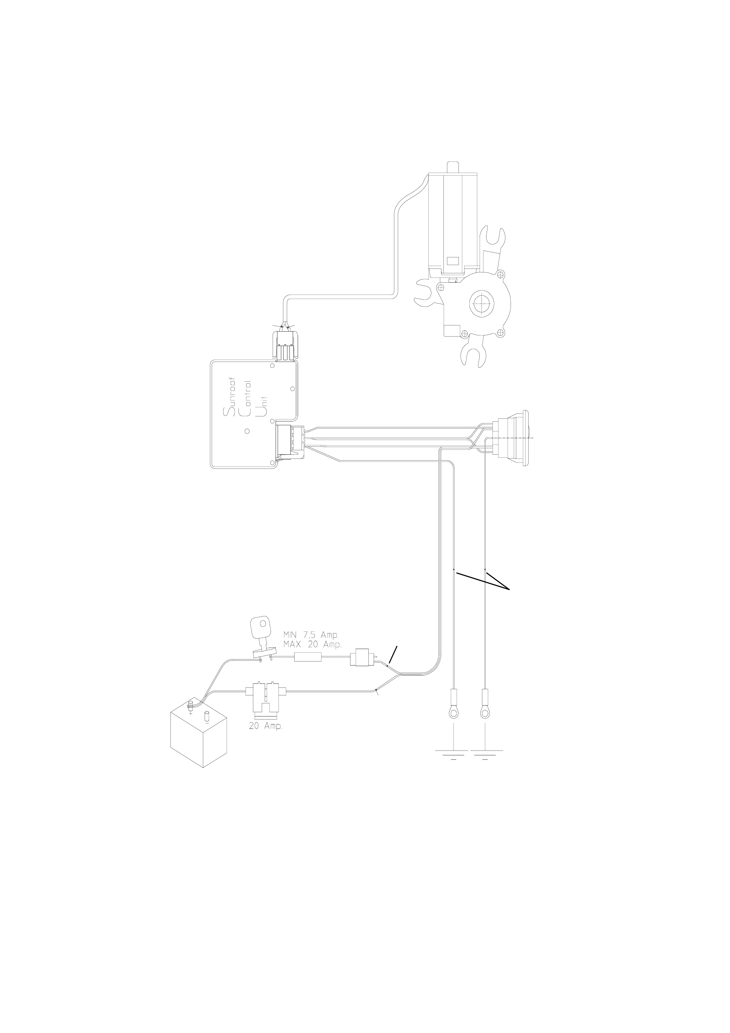
TESTING ELECTRICAL COMPONENTS
Make sure that during the test of electrical components, the TVS unit is connected to a power source containing
12 to 14V. If the Sunroof is installed, the battery needs to be attached and operable. During testing the
ignition/accessory switch should be ON. This test can be accomplished with a test light or voltage meter. Cable
harness and motor inspection requires the headliner to be removed.
Fuse
Visually inspect the fuse for damage.
Wire Harness
Check if the power supply on the red and red/black wires is OK. Inspect for broken/damaged wires. Inspect for
proper connection to the sunroof control unit. The wire harness connector is numbered to aid in proper installation
1 = red
2 = brown / red
3 = brown
4 = green
5 = red / black
Switch
Inspect for proper po wer supp l y to the T VS operating s wi tch, ac c omplishe d by using a tes t li ght on t he c on nector at
the switch bracket, operate switch connector to assure movement in front and rear sliding positions.
Motor
Disconnect the motor wire (gr een/black ) from the sunroof contr ol unit. Dism ount the m otor. Usin g a dou ble wire of
sufficient length, connect direct to battery, inspect the motor for proper operation in both directions. This is
accom plished b y r eversing th e connection of the doub le wire. The m otor has an inbuilt therm al cut-out device that
automatic ally switches the m otor off during periods of overload. Af ter a cooling d own period t he motor will f unction
properly.
Sunroof Control Unit
Testing is covered in the electric trouble-shooting guide. The following failures could be the result of a broken
Sunroof Control Unit
• Auto close function defective.
• Soft touch operation defective
• Comfort positio n can not be progr am med
• 4 step down option defective
REPAIRS
This chapter describes all repairs for the TVS 40 series.
Motor Replacement
1. Remove or drop rear of headliner to access motor cover.
2. Remove cover, motor now drops down.
3. Disconnect the motor wire from the sunroof control unit.
4. Connect new motor to sunroof control unit.
5. Inspect motor for proper operations in both directions.
6. Remount motor and motor cover
7. Inspect the unit for proper electrical and mechanical functioning.
1. Reinstall headliner.
Sunroof Control Unit (S.C.U.) - Replacement
1. Remove or drop rear of headliner to access motor cover.
2. Utilising a manual crank, vent the panel completely.
3. Remove the LH mechanism cover.
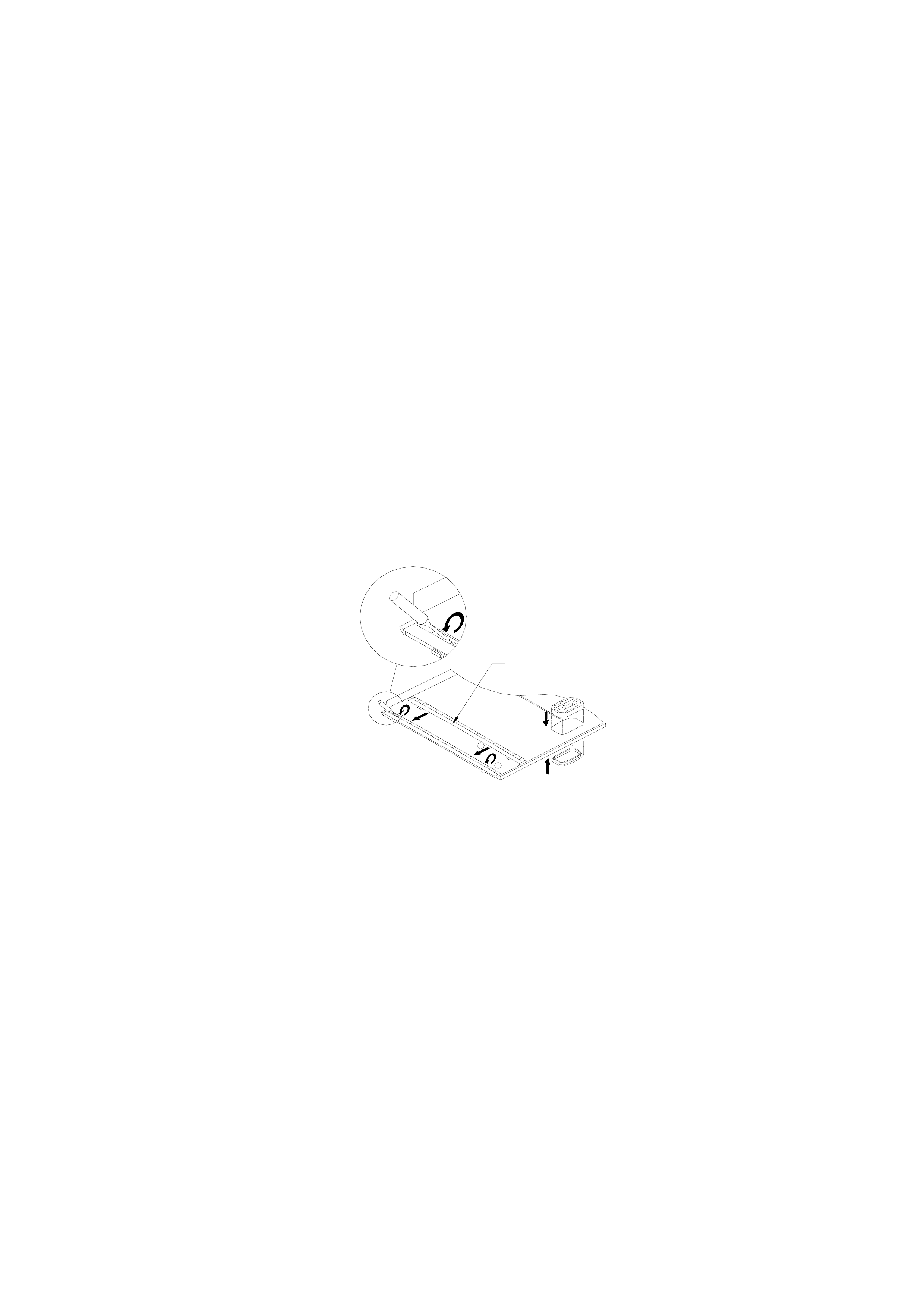
4. Utilising the manual crank, close the glass panel (1.5 revolutions) access the 2.5 mm brass hole with a pin.
Venting the panel, turn crank 0.25 revolution forward. The pin stops the mechanism at the desired location
(see Figure J-3).
FIGURE J-3
5. Remove cover, motor now drops down.
6. Disconnect the motor wire from the S.C.U and remove the motor.
7. Disconnect the wir e harn es s from the S.C.U.
8. Remove the S.C.U. with screw, drop the front, slide back.
9. Inspect th e new S.C.U. f or proper ali gnment of spots on gear wheel (s ee Figure J-4). Droppin g the front of the
S.C.U. low enough for cable clearance slide forward, engage lip of cable plate in S.C.U. slot. Straighten S.C.U.
horizontally and tighten screw.
FIGURE J-4
NOTE: If the spots are not aligned, turn the top mount cable gear until each spot appears aligned over one
another in the view finders.
10. Reconnect both wire connectors to the S.C.U. and remount motor and cover.
11. Check proper functioning of sunroof
12. Mount headliner.
13. Remount the LH mechanism cover.
Synchronization of the Sunroof Control Unit (S.C.U.)
1. Remove or drop rear of headliner to access motor cover.
2. Utilising the manual crank, vent the panel completely.
3. Remove the LH mechanism cover.
4. Utilising the manual crank, close the glass panel (1.5 revolutions) access the 2.5 mm brass hole with a pin.
Venting the panel, turn crank 0.25 revolution forward. The pin stops the mechanism at the desired location
(see Figure J-3).
5. Remove cover, motor now drops down.
6. Disconnect the motor wire from the S.C.U.
7. Disconnect the wir e harn es s from the S.C.U.
8. Remove the S.C.U. with screw, drop the front, slide back.
9. To align the two spots in the view finders, turn the exposed black cable gear mounted in top center of the
S.C.U. When each spot appears directly in line with the other, top to bottom, stop
NOTE: If the spots are not aligned turn the top m ount cable ge ar until eac h appears aligne d over one another
in the view finders.
10. Remount S.C. U. dropping the front of the S.C.U. low enough f or cable cle arance, sli de forward, engage lip of
cable plate in S.C. U. slot. Straighten S.C.U. horizo nta lly a nd tig hte n scr ew.
11. Reconnect both wire connectors to the S.C.U.
12. Check proper functioning of sunroof
13. Mount headliner.
14. Remount the LH mechanism cover.
Drive Cables Replacement
1. Remove covers, panel, drain channel, wind deflector and sunshade or trim tray and ventilation tray and
adjustment bracket.
2. Place mechanism in closed position.
3. Remove rear of headliner to access motor cover.
4. Remove motor cover, motor now drops down.
5. Disconnect the motor wire from the sunroof control unit.
6. Remove the S.C.U. with screw, drop the front, slide back.
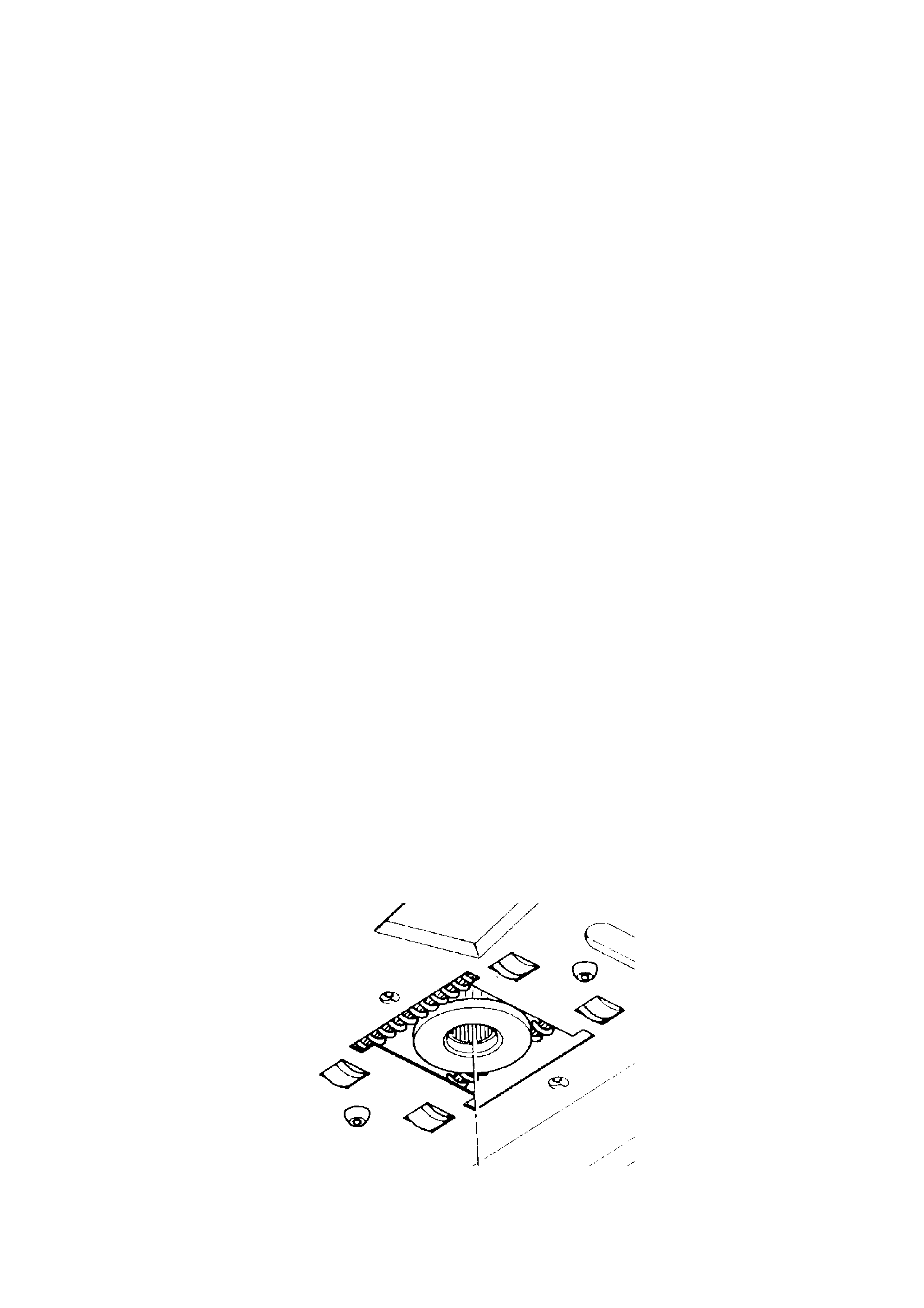
7. Remove the ge arwhe el hous ing b y rem oving the two screws.
8. Remove gearwheel by inserting screwdriver, push forward, it drops down (see Figure J-5).
FIGURE J-5
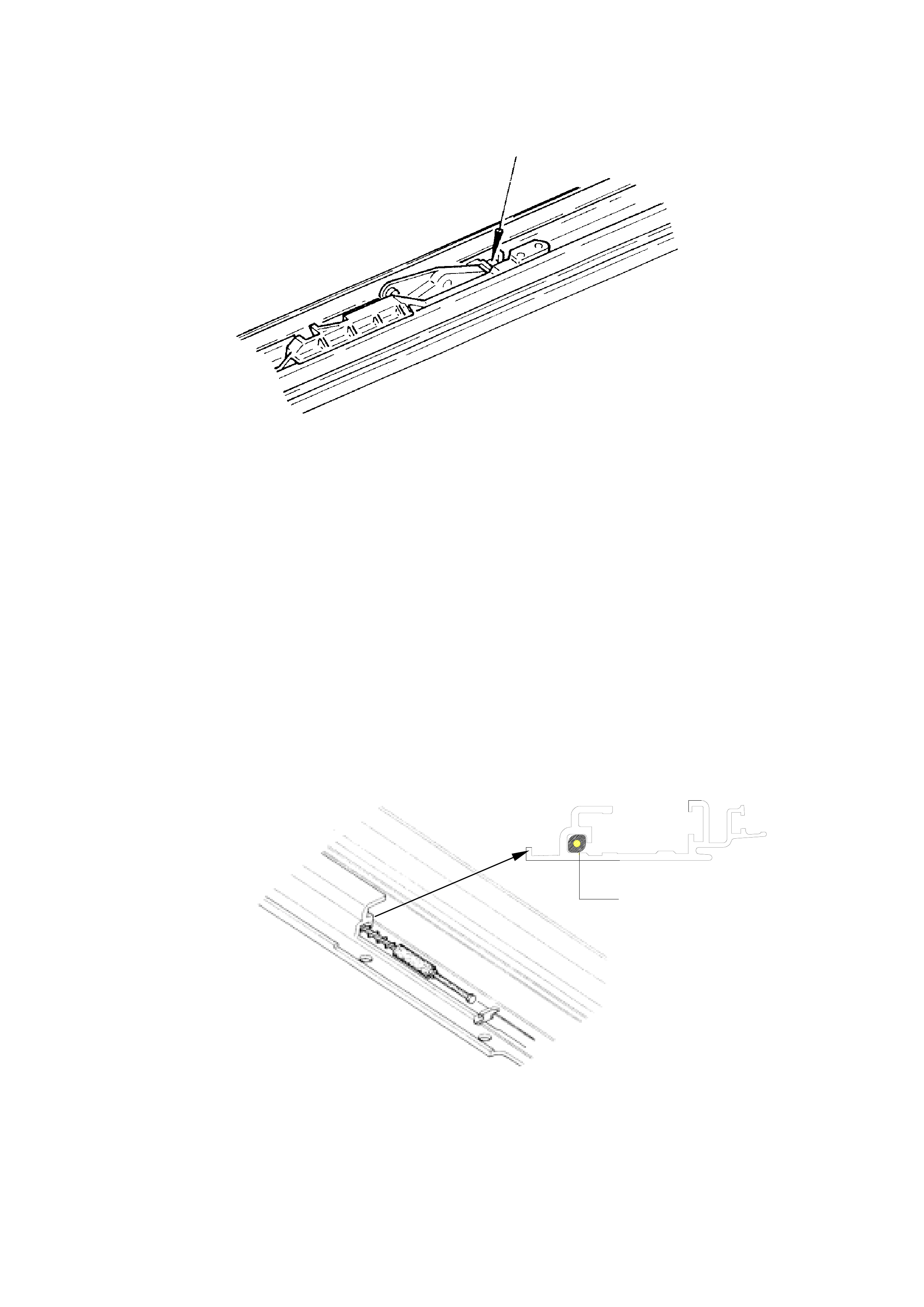
9. Place a s cre wdriver in t he m echanism as indicated in Figur e J-6. Push t his m ec hanism r earward int o th e s lide
position. Continue pushing backwards by placing hand on front of mechanism, 3 locator screws become
accessible.
Figure J-6.
10. Remove the locator being careful to remember the positioning of screws and the blocking catch.
11. Pull mechanism all the way forward.
12. Push the mechanism into tilt position as in step 9. Be sure you do not inadvertently dislodge the m echanism.
Keep the front of the mechanism down.
13. Remove the front screw and slide the retraction mechanism forward. Do not take out.
14. Slide mechanism in tilt position further forward.
15. Remove the tor x screw which c onnects the cur ve on panel t o the adjus tment brack et. Remove th e aluminium
curve on panel from the long lever. Pivot the adjustment bracket forward.
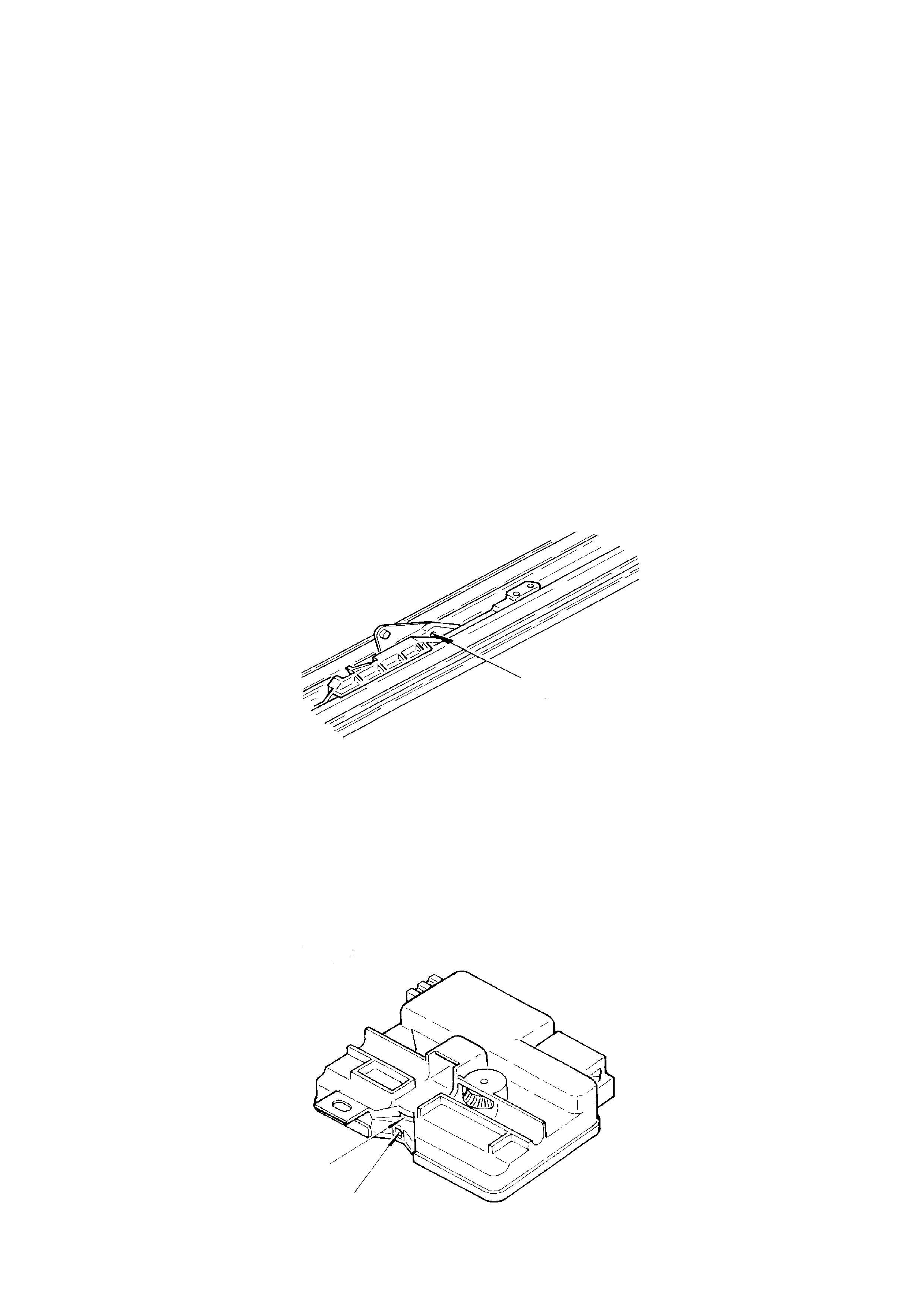
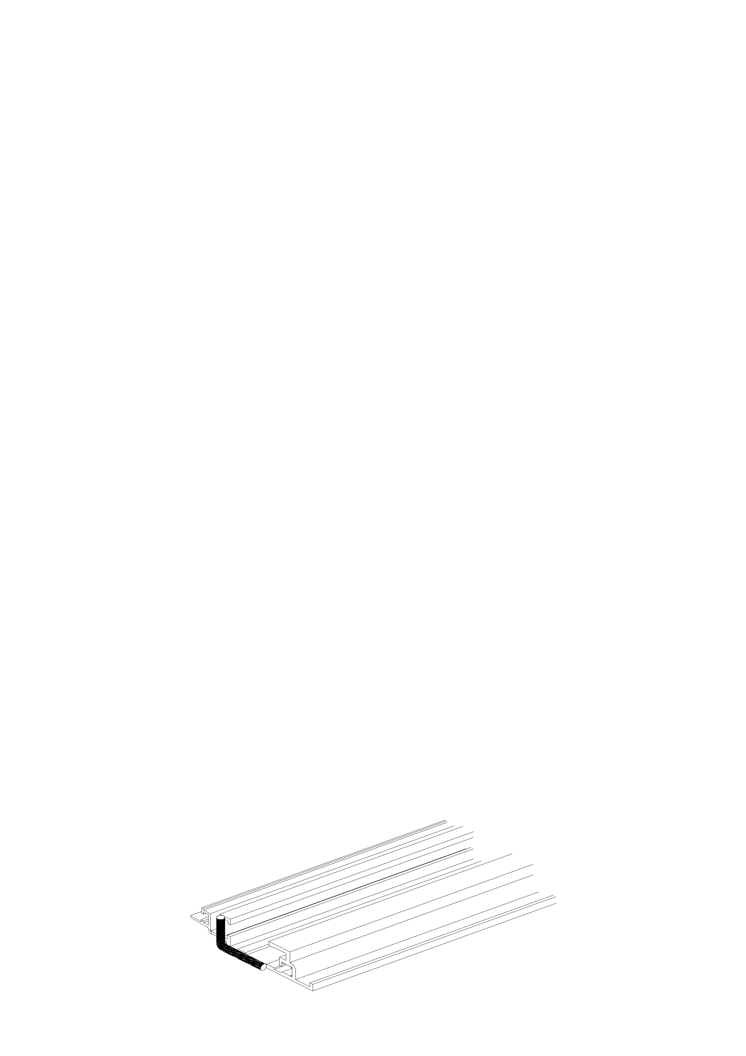
16. You can now see the cable. Lift out cable and pull forward out of the guide rail track.
17. Inspect for proper length of new cable, grease and slide into rail. Make sure the oval shaped copper head of
the cable seats firmly and diagonally across the guide channel (see Figure J-7).
FIGURE J-7
18. To check that cable is positioned properly grasp long lever in tilt position with one hand, the pivoting
adjustment bracket in the other hand and slide backwards, it should slide into place (if blocked turn cable
slightly to reseat copper oval head properly).
19. Pivot arm of adjustment bracket back down into place. Slide the curve on panel back into place over cap on
long lever and remount the torx screw.
drive cable

20. Push m ec hanis m into sl ide pos it io n as in s te p 9 ( h ol d adj ustment br acket st able while do ing s o) . If mec hanism
stops after approximately 100 mm (4 in.) preventing a full rearward positioning, you failed to hold the
adjustment bracket stable, repeat step 20.
21. Slide whole mechanism rearwards to allow remounting of locator.
22. Slide the retraction rearwards, remount screw and locator.
23. Repeat steps 10 through 22 to replace other cable.
24. Slide both LH/RH mechanisms to the front position.
25. Push LH/RH mechanisms to closed position. Insert a pin in each 2.5 mm brass hole. (pointed object). Slide
mechanism forward until pin stops the mechanisms movement at the desired location (see Figure J-3).
26. Mount the new gearwheel. Being sure to center it evenly between the walls of the hole in the motor bracket.
Note that the c ore or cent er of the gear has splines (teet h). The spli nes do not exten d completel y to one side
of the gears inner core. This is the down (bottom) side for mounting (see Figure J-5).
27. Mount the new gearwheel housing.
28. Mount the sunroof control unit. Inspect to be sure the two timing spots are aligned in the view finders (top to
bottom) (see Figure J-4). Dropping the front of the S.C.U. low enough for cable clearance slide forward,
engage lip of cable plate in S.C.U. slot. Straighten S.C.U. horizontally and tighten screw.
NOTE: If the timing spots are not aligned, turn the top mount cable gear until each appears aligned over one
another in the view finders (see Figure J-4).
29. Connect the motor to the sunroof control unit (wire one way connector).
30. Remount motor and cover, replace screws.
31. Inspect the sunroof for proper electrical and mechanical functioning.
32. Remount headliner.
33. Remount adjustment bracket, sunshade or ventilation tray and trim tray, drain channel, panel, wind deflector
and mechanism covers.
34. Final inspection of unit.
Timing Of The Drive Cables
1. Fully tilt panel
2. Remove LH/RH mechanism covers.
3. Fully close panel.
4. Drop rear of headliner to access motor cover plate.
5. Remove motor cover, motor now drops down.
6. Disconnect sunroof control unit wires and remove the motor.
7. Dismount sunroof control unit with screw, drop the front and slide back.
8. Remove the ge arwhe el hous ing b y rem oving the two screws.
9. Remove gearwheel by inserting screwdriver, push forward, it drops down
(see Figure J-5).
10. Push m ec hanisms LH/RH to c losed p os ition. Ac c ess eac h 2.5 m m bras s hole with a p in ( p oin ted objec t). Slide
mechanism forward until pin stops the mechanisms movement at the desired location (Figure J-3).
11. Mount the new gearwheel. Being sure to center it evenly between the walls of the hole in the motor bracket.
Note that the c ore or cent er of the gear has splines (teet h). The spli nes do not exten d completel y to one side
of the gears inner core. This is the down (bottom) side for mounting (see Figure J-5).
12. Mount the new gearwheel housing.
13. Mount the sunro of control unit. Insp ect to be sure the two white t im ing spots ar e alig ned in the view fin der (to p
to bottom) (see Figure J-4). Dropping the front of the S.C.U. low enough for cable clearance slide forward,
engage lip of cable plate in S.C.U. slot. Straighten S.C.U. horizontally and tighten screw.
NOTE: If the white timing spots are not aligned, turn the top mount cable gear until each appears aligned over
one another in the vi e w finders (s ee Figure J-4).
14. Connect the motor to the sunroof control unit. (wire one way connector).
15. Remount motor and cover, replace screws.
16. Inspect the sunroof for proper electrical and mechanical functioning.
17. Remount headliner.
18 Remount the LH mechanism cover.
19. Final inspection of unit.
Adjustment Bracket Replacement
1. Fully tilt panel.
2. Remove the panel.
3. Remove adjus tment brack et by r emovin g front reta ining c lip and torx scre w. The adjustm ent brack et is m oved
sideways from the long lever in rear and mechanism in front.
4. Remove the curve on panel by taking off retaining clip. Mount curve on panel to new adjustment bracket.
5. Reverse above sequences to reinstall the adjustment bracket.
6. Remount panel.
7. Inspect sunroofs electrical and mechanical functioning.
Seal Replacement TVS 40 Series
1. Dismount LH / RH mechanism covers, glass panel and exterior covers.
2. Remove seal from panel.
3. Remove all foreign debris from around glass frame.
4. Install new seal, beginning at center front of glass frame retaining channel.
5. Utilising your thumbs, insert seal with enough pressure to be sure of flushness (tight to frame).
6. Trim the glass seal length. when cutting excess leave approximately 6 mm extra then work it into retaining
channel.
7. Remount the panel.
8. Mount the LH / RH mechanism cover.
Retraction Mechanism Replacement
1. Retract panel completely.
2. Remove the wind deflector.
3. Remove the two screws and take the retraction mechanism forwards out of rail.
4. Install new retraction mechanism in rail.
5. Remount the wind deflector.
6. Inspect for proper functioning.
Guide Rail Mechanism Replacement
1. Remove LH/RH mechanism covers, panel, drain channel, wind deflector and sunshade.
2. Tilt mechanism completely.
3. Fully retract mechanism.
4. Remove the locator, retraction mechanism and rail screw.
5. Remove wind deflector mounting nuts.
6. Slide rail sideways to unlock, then lift front up.
7. With rail front up, grasp retractor mechanism and remove.
8. Fully close mechanism.
9. Lift and pull rail slowly forward over mechanism, as soon as the front of drive cable appears at end of guide, lift
out cable, now pull mechanism carefully forward and lift out. Inspect the new replacement mechanism for
cleanliness and completeness.
10. Slide the mechanism rearward out of rail for cable installation access.
11. Install cable, then push mechanism forward on rail (maintain access to rear rail area).
12. Apply a bend of liquid butyl as indicated on Figure J-8.
Figure J-8

13. Slide rai l rear ward over m ec hanism and drive cable whil e hold in g th e front of the mechanis m in pl ace. As s oon
as the ra il is full y extend ed rearward, dr op the front t o frame and pus h rail rear ward into ra il stop. L ine up the
screw holes for proper positioning.
14. Retract mechanism totally.
15. Lift front of rail to reinstall retractor mechanism.
16. Drop rail down, push inboard until it “locks” in place.
17. Remount all new rail screws starting at front for proper positioning. Use original positioning of screws by size.
18. Replace wind def lec tor m ounting nuts loosely.
19. Tilt mechanism completely.
20. Inspect for proper mechanical functioning of mechanism.
21. Remount sunshade, drain channel, panel and wind deflector.
22. Inspect functioning of sunroof, reinstall LH/RH mechanism covers.
Blocking Catch Replacement
1. Remove the LH/RH mechanism covers and panel.
2. Fully retract mechanism.
3. Remove locator.
4. Fully tilt mechanism.
5. Remove blocking catch by lifting out.
6. Clean out broken blocking catch debris.
7. Install n ew block ing catch in mec hanism, ins ert circ ular eye s tud into m echanis m m aking sure s econd sm aller
stud falls cleanly into mechanism slot.
8. Fully retract mechanism.
9. Remount locator.
10. Inspect for proper mechanical functioning.
11. Remount the panel and LH/RH mechanism covers.
Seal adjustment
The proper positioning of the panel should result in the seal firmly contacting either the EPDM trim ring or flanged
metal circ umference of the s unroof opening. If the pa nel fits prop erly but ga ps rem ain between seal and tr im ring it
can be corrected as follows:
1. Adjust panel properly against the rear of the trim profile (according to instructions in the installation manual
chapter 5.3).
2. With a grease pencil mark the boundaries of insufficient contact on the panel (at the front).
3. Remove panel.
4. In the areas marked, a spacer will be inserted inside the rubber seal. (see Figure J-9). Use a vinyl tube with
outer diameter of 3 mm (.12 in) for spacer material.
5. Glue the spacer material to the seal with super glue.
FIGURE J-9
6. Remount panel and adjust according to the installation manual chapter 5.3.
EXTRACTS FROM THE HOLLANDIA INSTALLATION MANUAL
3.2 Side support brackets centre and rear
1. Remove c lamps and g luetem plate after 30 m inutes. Leave the j acks in pl ace!. Check the curvat ure of the car
roof near the centrebrace with curvature gauge.
If the car roof is more curved than the curvature gauge then a correction can be made by slightly raising the
jacks until the curvature of the roofskin is equal to the curvature of the curvature gauge.
If the curvature of the roofskin less curved than the curvature gauge then a correction can be made by
lowering the jacks a little bit until the curvature of the roofskin is equal to the curvature gauge.
Attention: excessive correction can cause distortion in the roofskin.
2. For each car model the side support brackets have to be cut and bent to fit. Bending, cutting and punching
equipment can facilitate this work. Place the wide brackets on each side close to the centrebrace. The small
brackets are mounted as far to the rear as possible, between the side rail and the frame.
3. The plastic cover must be on the bracket side supporting the Tilt Vent Slide frame.
4. Wrap paper masking tape around the part of the bracket that will be attached to the side rails. This avoids
possible creaking.
5. Mount the support brackets to the side rails with the supplied self tapping screws.
6. Remove the jacks.
7. Check the curvature of the car after installing the support brackets.
4.1 Interior Trim
5. Mount the left and right guide by placing the integrated slide through the opening in the side of the
sunshade.Lift the springs up with a screwdriver to apply tension on the springs (figure 10).
GUIDE
1
2
Figure 10 - Finishing the sunshade
5.3 Glass panel (TVS 40)
1. Slide mechanism to tilt position.
2. Inspect rubber seal and glass panel for damage.
3. Place the height adjustment curve, (which is at the rear of the glass panel), over the mechanism. Place vertical
front lips on panel between the RH and LH mechanisms.
4. Lift the mechanism mounting bracket from the inside and install 2 front and centre screws, leaving the 4
screws loose.
5. Put glass panel in closed position.
6. Adjust the glass panel to the f ront. Check with f or exam ple a b usines s card the tension of the sea l a gainst the
trim ring at the rear.
7. Tighten both centre screws.
8. Adjust height at the front and tighten front screws.
9. Adjust height at the rear b y loose ning t orx s crews of the adj ustm ent c urve, adj ust the g lass leve l with r oof sk in
and tighten screws (see Figure 14). Torque for all M5 screws is 3.5Nm.

HEIGHT ADJU STMENT CURVE
LEVER
FRONT SCREWS
CENTRE SCREWS FIXING POINT HEIGHT
GLASS PANEL
GLASS PANEL
ADJUSTMENT CURVE
10. Check functioning of mechanism and adjustments. Repeat operation 6 till 9 to readjust the glass panel if
necessary.

3. FIRE EXTINGUISHER
3.1 GENERAL
HSV VT2 models are fitted with a HSV design fire extinguisher. The extinguisher is located in the rear luggage
compartment.

3.2 SERVICE OPERATIONS
The fire extinguisher should be subjected to a regular visual inspection in accordance with the instructions on the
extinguis her. Par ticu larl y, the extinguish er should be ins pected f or dam age and t o ens ure th at the i ntegral press ure
gauge registers the appropriate internal pressure. When discharged or when the internal pressure is outside the
prescribed limits, the extinguishers should be serviced and re-charged by an appropriate supplier. New
extinguishers are available through the HSV spare parts systems.

4. HSV INTEGRATED SECURITY SYSTEM (VS III AND VT)
4.1 GENERAL
The ne w H SV I nte grated Sec urity S ystem VSII I M alo o o nly and VS G ra nge (IS S) is f itte d as s tan dard equ ipment to
all HSV VS models. The ISS is a micro-processor controlled immobiliser, which automatically isolates essential
electrical circuits when the ISS is armed and accessory or ignition ‘ON’ is detected. The immobiliser is disarmed
using a valid ignition key code and uniquely coded black tags which contain a small chip incorporating specific
codes. The HSV ISS has been improved for the VS range of vehicles. The vehicle no longer requires use of the
black ISS tag each time the vehicle is started. T he ISS records th e ignition ke y code and will disarm when a valid
vehicle ignition k ey is detected at the k ey s lip r ing. Up to s even v ehicle ig nition k eys and s even I SS blac k tags c an
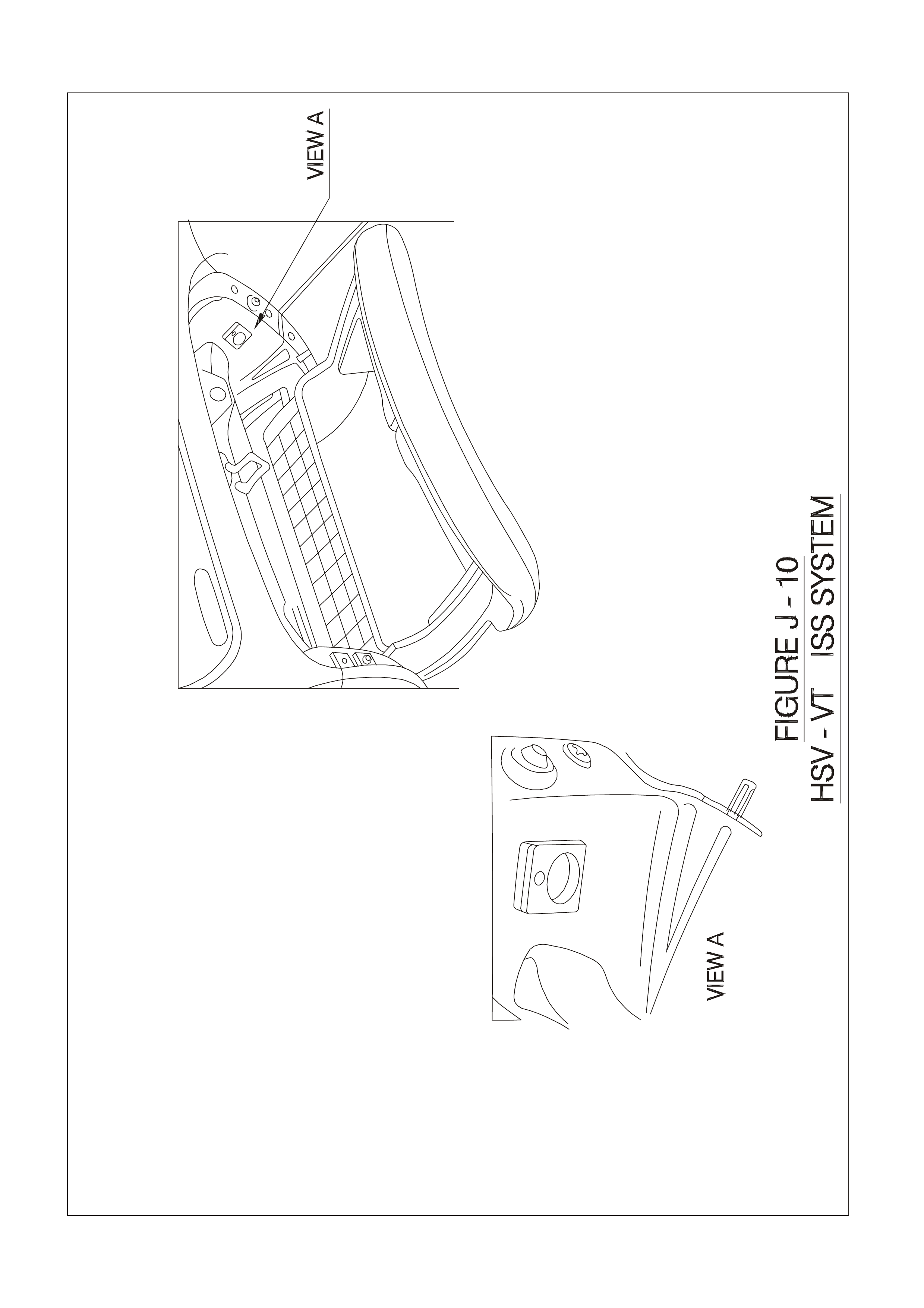
be assigned to the vehicle if required. Refer to Figure J-10 for ISS Key Cavity Location (Status Monitor).
NOTE: IF THE KEY-HEAD BECOMES UNSERVICEABLE AND FAILS TO DISARM THE ISS, THE ISS MAY BE
DISARMED USING THE BLACK TAG UNTIL A REPLACEMENT KEY IS INTRODUCED.

4.2 INTRODUCING NEW KEYS
A red MA STER TAG is also suppli ed with each ISS. This ta g is used to place the ISS into ` Learn’ m ode: touch ing
the red tag to t he s ta tus monitor ( loca ted in the gl ov e box ) wil l caus e the L ED f las h r at e to inc rease which i nd icates
that learn m ode is operative . In this m ode, codes for lost tags/k eys may be over written and new keys/tags may be
introduc ed as f ollo ws:
• With the ISS in learn mode, insert ignition key and turn ignition switch to ‘IGN ON’ position. The status
monitor will cha nge to indic ate ig nitio n k ey code has been s ucces sf ully stor ed (L ED g oes of f ). ISS wil l retur n
to normal mode. Retouch red tag if more ignition keys are to be introduced.
• W ith ISS in learn m ode, touch new black tag to receptac le for approx imatel y 2 secs . Status m onitor LED will
change to indicate ke y code has b een s ucc es s f ully stored ( LED on) . ISS will retur n to normal mode. Retouch
red tag if more black tags are to be introduced.
NOTE: THE ISS WILL RECOGNISE SEVEN KEY AND TAG CODES. IF A TAG OR KEY IS LOST, THE
REMAINING/ NEW CODES MUST BE ENTERED S EVE N T IME S TO ENSU RE THAT THE CODE F O R T HE LOST
KEY OR TAG HAS BEEN OVERWRITTEN AND CANNOT DISARM THE ISS.
NOTE: RED TAGS MUST BE STORED IN A SECURE LOCATION REMOTE FROM THE VEHICLE. DO NOT
STORE RED TAG IN VEHICLE. LOSS OF A RED TAG WILL REQUIRE REPLACEMENT OF THE ISS SYSTEM
IF KEYS ARE LOST OR DAMAGED

4.3 SERVICE OPERATIONS
If an ignition key has been damaged and does not transfer a valid code, the ISS may be disarmed by touching a
valid black tag to the status monitor: this will transmit code to the BCM and enable vehicle start No periodic
servicing of the ISS is required and no additional information is provided or available on the system. HSV dealers
are not authorised to carry out any servicing operations on the ISS system. All requests for information and/or
assistanc e are to be for war de d d irec tly to the S ervice Manag er at HS V. Bef ore mak ing th is r equ es t an d at an y time
that correct operation of the ISS is suspected, the following functional check should be performed:
• Check ISS status monitor (located in glovebox) to ensure ISS is in armed mode—i.e. slow flash
• Place a piece of tape over th e ign ition k ey slip r ing co ntact t o bre ak the el ectric al c ircuit between ignit ion k e y
and ignition bar re l sli p ring,
• Turn ke y to start positio n—veh ic le shou ld not star t.

5. HSV SPECIFIC BODY CONTROL MODULES.
5.1 GENERAL
HSV specif ic Bod y Control Modul es (BC M’s) are sta ndar d on VT II Senat or S ignatur e an d W H Grange M ode ls. T he
modules have the same physical dimensions and connections as the standard BCM’s but have different software
which is specific to HSV. Both the VTII Senator Signature and WH Grange models have their own specific module.

5.2 CHANGING BCM’S.
If the BC M is ch ang ed, r ef er to HS V Embedded Secur ity System, Sectio n 6. 2 or Section 6.3 in t he Holden Specia l
Vehicles Service Inform ation Su ppl ement.
If extra or new keys are required, refer to HSV Embedded Security System, Section 6.4 in the Holden Special
Vehicles Service Inform ation Su ppl ement.

6. HSV EMBEDDED SECURITY SYSTEM VTII AND WH.
6.1 GENERAL
The ne w HSV Embedded Sec urity S ys tem (ESS) is fitted as s tandard equ ipment to all HS V VTII and W H m odels.
The ESS is a micro-processor controlled immobiliser which automatically interrupts essential electrical circuits
when in “armed mode”. The ESS stores the BCM’s security code and when the car is started it reads this code from
the SCI bus . If this c od e is d if f erent from the st ored one the E SS ent er s armed m ode and pr events t he veh ic l e f rom
starting.

6.2 LINKING THE ESS TO A NEW BCM AT THE CAR DEALER – BCM IN WARR ANTY.
If the BC M requires re placement within the BCM warranty per iod, the Dea ler shall be su pplied with a replacem ent
BCM and t wo new ke ys , all program med with the s ame BCM secur ity code as the or iginal BCM. In this c ase, the
replacement BCM and new keys are simply fitted to the vehicle. No ESS specific requirements are needed.

6.3 LINKING THE ESS TO A NEW BCM AT THE CAR DEALER –
BCM OUT OF WARRANTY.
W hen a BCM requires rep lac ement outside the BCM warr a nty period the Dea ler s ha l l ne ed t o o bta in a rep lacement
BCM and keys from Holden’s Service Parts Operation (HSPO). The replacement BCM and Keys will not contain
the same BCM Security Code as the original BCM.
When a new BCM with different BCM security code is fitted to the vehicle, the dealer will have to do the following:
−Link the BCM and PCM.
−Program a new key to the BCM.
TECH 2 must be connec ted to the vehicle dia gnostic conn ector whilst t he key is be ing programm ed and/or E SS is
being link ed to the v ehicle. T he L ink Ena ble Pr oc edure is requ ired to be perf orm ed t wice t o a llo w an all ne w k ey t o
be programmed and also allow the ESS learn to learn the BCM security code. The procedure for programming a
new key to a new BCM and linking the ESS to the vehicle is as follows:
1. Fit new BCM to the vehicle.
2. Ensure driver's door is closed, driver's door is unlocked, and wash-wipe switch is off.
3. Place new key into the ignition barrel.
4. Turn ignition on. Verify ESS beeps 5 times.
5. TECH2 must be operating in the “Normal Mode” submenu of the Body Control Module sub-menu.
6. Perform the Li nk Enab le Pr ocedur e ( se e Sectio n 6.5) . Wait 1 sec ond bet ween eac h lock unloc k to ens ure t he
door lock actuators function correctly during this procedure.
7. Verify that the ESS beeps twice. TECH2 reports ignition is at 12Vdc. The ESS has now entered “Key
Programming mode”.
8. Select Key Programming function – “All New Key” - from the security sub-menu in the body menu of the
TECH2. Enter BCM security code as requested by TECH2. Complete key programming as requested by
TECH2.
9. Turn ignition off and wait for 2 seconds. Turn ignition on.
10. Verify ESS beeps 5 times. (At this stage the ESS is in “armed mode”).
11. TECH2 must be operating in the “Normal Mode” submenu of the Body Control Module sub-menu.
12. Perf orm the Link Enable Proc edure (see S ection 6.5). Wait 1 second bet wee n each loc k unlock to ensure the
door lock actuators function correctly during this procedure.
13. Verify that the ESS beeps twice. TECH2 reports ignition is at 12Vdc.
14. Link the PCM to the BCM using TECH2. ESS beeps twice (ESS has now learned the BCM security code).
15. Turn ignition off. Wait until TECH2 programming is complete.
16. Turn ignition on.
17. Turn ignition off. Wait 2 seconds.
18. Turn ignition on.
19. Verify ESS beeps once. The ESS is now operating in “normal mode”.
20. Crank engine. Verify vehicle starts as normal.

6.4 KEY PROGRAMMING MODE.
Once the ESS has been placed into key programming mode the ESS will behave as if in “sleep mode” for one
ignition c yc le only. This allows f or the one ignition c yc le that is re quired to pr ogram a ne w key to a ne w or existin g
BCM. T he ESS will enter “normal m ode” for the nex t ignition cycle. If the BCM is a n ew BCM in the vehicle with a
new security code, the ESS will then enter “armed mode” as expected.
Programming Extra Keys to the Vehicle. Programm ing m ore ke ys for the ve hicle c an be achi eved us ing TECH2
once the ESS has been re-linked to the vehicle as described as follows:
1. Ensure driver's door is closed, driver's door is unlocked, and wash-wipe switch is off.
2. Place new key into the ignition barrel.
3. Turn ignition on. Verify ESS beeps 5 times.
4. TECH2 must be operating in the “Normal Mode” submenu of the Body Control Module sub-menu.
5. Perform the Link Enab le Pr ocedure ( see Sect ion 6.5). Wait 1 s econd betwe en each lock unl ock to ens ure th e
door lock actuators function correctly during this procedure.
6. Verify that the ESS beeps twice. TECH2 reports ignition is at 12Vdc. The ESS has now entered “Key
Programming mode”.
7. Select Key Programming function – “Ex tra Ke y” - fr om the secur ity sub- m enu in the bod y menu of the TECH 2.
When TECH2 requests ignition to be cycled with the existing key, leave the new key in the ign iti on b arr el and
instead, pr ess th e u nl ock button on th e existing k ey. Verif y the E SS bee ps once an d the T heft Deter rent LED
stops flashing. Complete key programming as requested by TECH2.
8. Turn ignition off and wait for 2 seconds.
9. Turn ignition on. Verify ESS beeps once. The ESS is now operating in “normal mode”.
10. Crank engine. Verify vehicle starts as normal.
Programming All New Key. Programming an All New Key for the vehicle can be achieved by performing the
follo wing proc ed ur e:
1. Ensure driver's door is closed, driver's door is unlocked, and wash-wipe switch is off.
2. Place new key into the ignition barrel.
3. Turn ignition on. Verify ESS beeps 5 times.
4. TECH2 must be operating in the “Normal Mode” submenu of the Body Control Module sub-menu.
5. Perform the Link Enab le Pr ocedure ( see Sect ion 6.5). Wait 1 s econd bet ween eac h lock unl ock to ens ure th e
door lock actuators function correctly during this procedure.
6. Verify that the ESS beeps twice. TECH2 reports ignition is at 12Vdc. The ESS has now entered “Key
Programming mode”.
7. Select Key Programming function – “All New Key” - from the security sub-menu in the body menu of the
TECH2. Enter BCM security code as requested by TECH2. Complete key programming as requested by
TECH2.
8. Turn ignition off and wait for 2 seconds.
9. Tur n ignition on . Verif y ESS beeps onc e and T heft Deterren t LED is off. T he ES S is now operating in “norm al
mode”.
10. Crank engine. Verify vehicle starts as normal.

6.5 LINK ENABLE PROCEDURE.
Each ESS has it’s own unique Link Enable Code (LEC), programmed into each ESS by HSV. This code
corresponds to a unique sequence of 10 vehicle body functions comprising of the following actions:
1. Drivers door. Open then Close
2. Drivers door. Lock then Unlock
3. Wash-Wipe. On then off.
Approximately 60,000 link enable codes are available. (Pull stalk towards steering wheel and release).
For the Link Enable Procedure contact:
Australian Arrow Pty Ltd
Customer Service quoting ESS PIN.
Telephone: (03) 9785 0792
Facsimile: (03) 9775 0954

6.6 SERVICE OPERATIONS.
In the event of a suspected ESS failure the following diagnostic procedure must be followed:
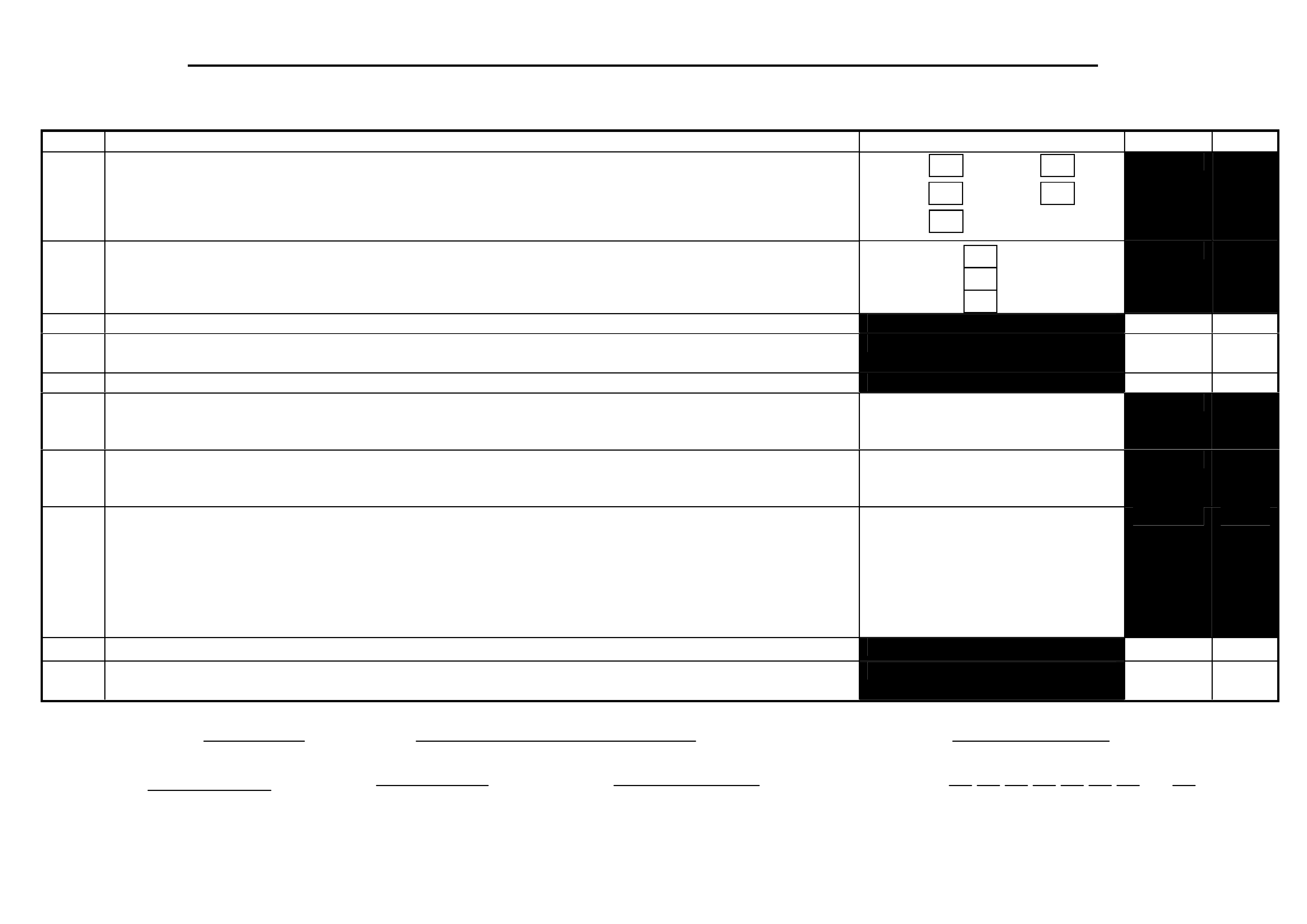
HSV – EMBEDDED SECURITY SYSTEM (ESS) CHECK SHEET (VT.II / WH / VY / WK / VZ).
In the event of a suspected ESS failure, fill in the following check sheet.
STEP ACTION MEASURED VALUE
YES NO
• What type of vehicle has the suspected ESS failure? VT.II : VY :
WH : WK:
VZ :
1 • Turn ignition to ON position and listen for the number of beeps. Zero beeps:
One beep:
Five beeps: Other:______
2 • With the ignition in the ON position, is the Theft Deterrent Led flashing?
3 • Turn Ignition switch to the Start position.
• Does the vehicle start?
4 • Has there been a BCM replacement?
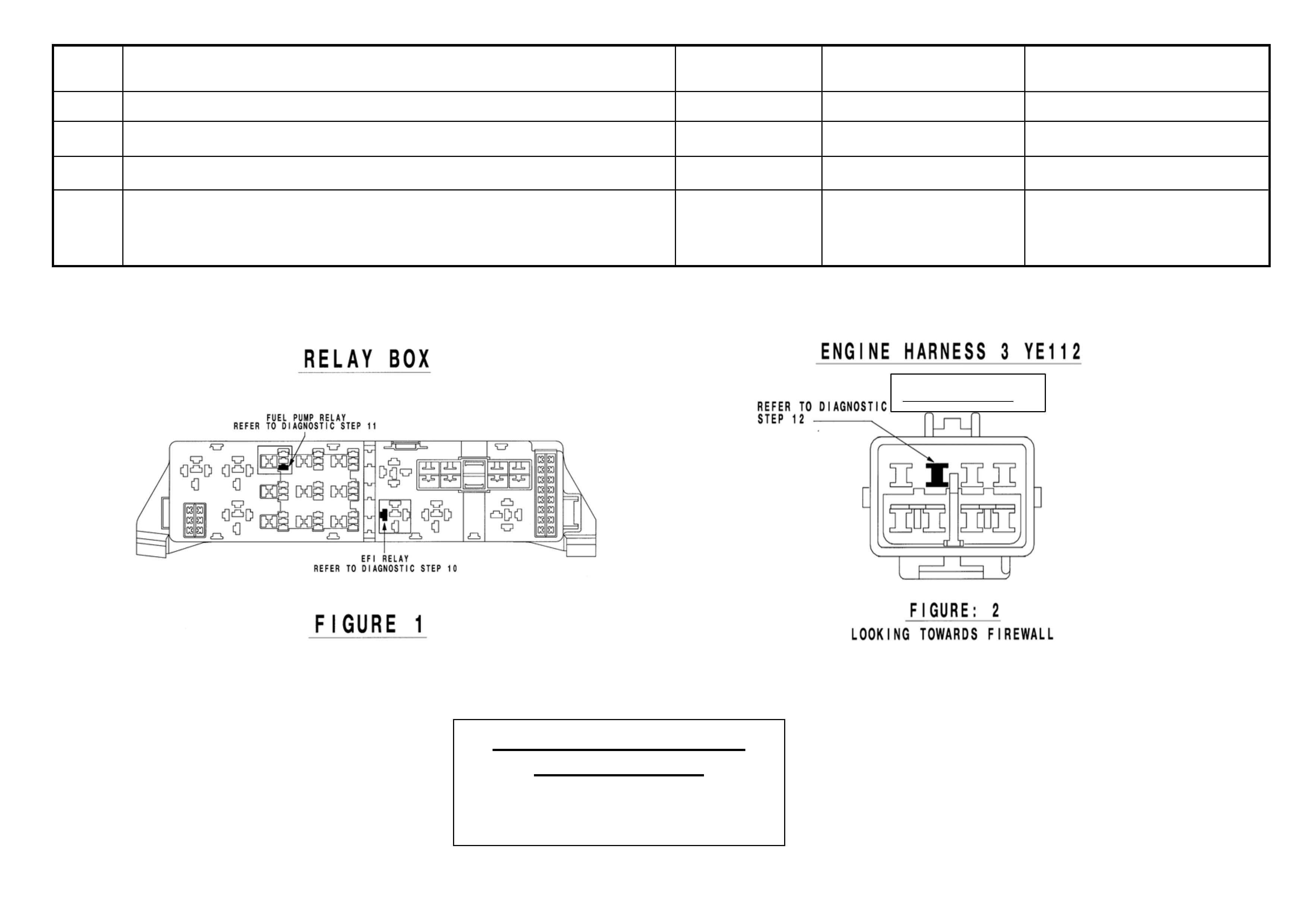
5 • Remove the EFI relay and back probe terminal 85 (as per figure 1 for VT.II / WH Vehicles or as per figure 3 for
VY / WK/ VZ Vehicles), with reference to Ground.
• With the Ignition switch to ON, measure DC voltage.
_____________ volts DC.
6 • Remove Fuel Pump relay and back probe terminal 1 (as per figure 1 for VT.II / WH Vehicles) or terminal.2 (as
per figure 3 for VY / WK Vehicles) , to measure continuity with ref. to Ground.
• Turn the ignition to ON, measure resistance.
_____________ Ohms.
7 • For VY / WK Vehicles Disconnect Engine Connector (X2 06 located a bove passenger kick panel ) and back pr obe
pin 9 (as per figure 4) with reference to ground.
• For VT.II / WH Vehicles Di s c on nect En gi n e Connector (YE112) and back probe pin (a s per fi g ure 2 ), wi t h
reference to Ground.
• For VZ vehicles Disconnect ECM connector A43 X1 and back probe pin 19 (as per figure 5) with reference to
ground.
• Turn the ignition to ON, measure DC voltage.
_____________ volts DC
8 • Is communications with Tech 2 active?
9 • With TDL flashing, operate “Unlock” button on the Remote Control.
• Does the TDL stop flashing?
Dealer Code: ISOVIN: Vehicle Build Date:
Km’s: ESS Pin No: BCM Part No: BCM Barcode No: .
This check sheet must signed by the Service Manager. ____________________________ Date: ____________
Fax the completed copy to Australian Arrow Customer Service. Facsimile: (03) 9775 0954.

HSV – EMBEDDED SECURITY SYSTEM (ESS) DIAGNOSTIC PROCEDURE (VT.II / WH / VY / WK / VZ).
STEP ACTION VALUE YES NO
1 • Turn ignition to ON position.
• Is one (1) beep audible? • Go to Step 2 • Go to Step 3.
2 • Turn Ignition switch to the Start position.
• Does the vehicle start? • System O.K, return
vehicle to
customer.
• Go to Step 11.
3 • Are five (5) beeps audible? • Go to Step 13. • Go to Step 8.
4 • Turn Ignition switch to the Start position.
• Does the vehicle start? • Go to Step 5. • Go to Step 6.
5 • Fill in the ESS check sheet and Contact Australian Arrow
Customer Service.
6 • Has there been a BCM replacement? • Go to Step 5. • Go to Step 14.
7 • Perform Serial Data Communications diagnostic as per Holden
Service Manual, then go to Step 5.
8 • Zero beeps were audible? • Go to Step 9. • Record number of beeps,
then go to Step 5.
9 • Turn Ignition switch to the Start position.
• Does the vehicle start? • Go to Step 5. • Go to Step 10.
10 • Remove the EFI relay and back probe terminal 85 (as per figure.1
for VT.II / WH vehicle), or (as per figure.3 for VY/WK/VZ
vehicle), with reference to Ground.
• With the Ignition switch to ON, Is the value as specified?
• 12 volts DC. • Go to Step 5. • Refer to Service Manual
and check Ignition
system.
11 • Remove Fuel Pump relay and back probe terminal.1 (as per figure.1
for VT.II / WH vehicle), or (as per figure.3 terminal.2 for
VY/WK/VZ vehicle), to check continuity with reference to
Ground.
• Turn the ignition to ON. Is the value as specified?
• Less than
one (1) Ohm.
• Go to Step 12. • Go to Step 5.
12 • For VT.II / WH vehicle, Disconnect Engine Connector (YE112)
and back probe pin (as per figure 2), with reference to Ground.
• For VY/WK vehicle, Disconnect Engine Connector (X206 located
above passenger kick panel), and back probe pin.9 (as per figure.4),
with reference to ground.
• For VZ vehicles Disconnect ECM connector A43 X1 and back
• 12 volts DC • Go to Step 5. • Go to Step 5.
probe terminal 19 (as per figure 5) with reference to ground.
• Turn the ignition to ON. Is the value as specified?
STEP ACTION VALUE YES NO
13 • Is the Theft Deterrent Led flashing? • Go to Step 4. • Go to Step 5.
14 • Is communications with Tech 2 active? • Go to Step 15. • Go to Step 7.
15 • With TDL flashing, operate “Unlock” button on the Remote Key.
• Does the TDL stop flashing? • Go to Step 5. • Refer to Theft Deterrent
System diagnostics in
Holden Service Manual.
(Grey C onn ector)
Australian Arrow Pty. Ltd.
Customer Service.
Telephone: (03) 9785 0792
Facsimile: (03) 9775 0954
2

7. ELECTROCHROMIC MIRRORS
7.1 GENERAL
Electrochromic mirrors are a standard fitment to all VT2 Senator Signature & Estate, & W H Grange vehicles. The
mirror features an electronically controlled mirror cell which changes colour in response to an applied electrical
voltage. This allows automatic darkening of the mirror during night driving when the headlamps of a following
vehicle shine on an integrated light sensor. This function only operates when the integral sensor detects low
ambient (i.e . at night tim e) . T he mirror also incorp orates t w o manuall y op erate d map lig hts - s epara t el y s witc hed f or
passenger and driver. (Lig hts also illum inate in conjunct ion with inter ior l am p when act ivated b y door switch es. T he
mirror operates autom aticall y however, an AUT O/MANUAL s witch provi des the dri ver wit h the option for the mir ror
to be darkened during low ambient light conditions regardless of presence or absence of following headlamps.
When reverse gear is selected, the mirror automatically lightens.
7.2 SERVICE OPERATIONS
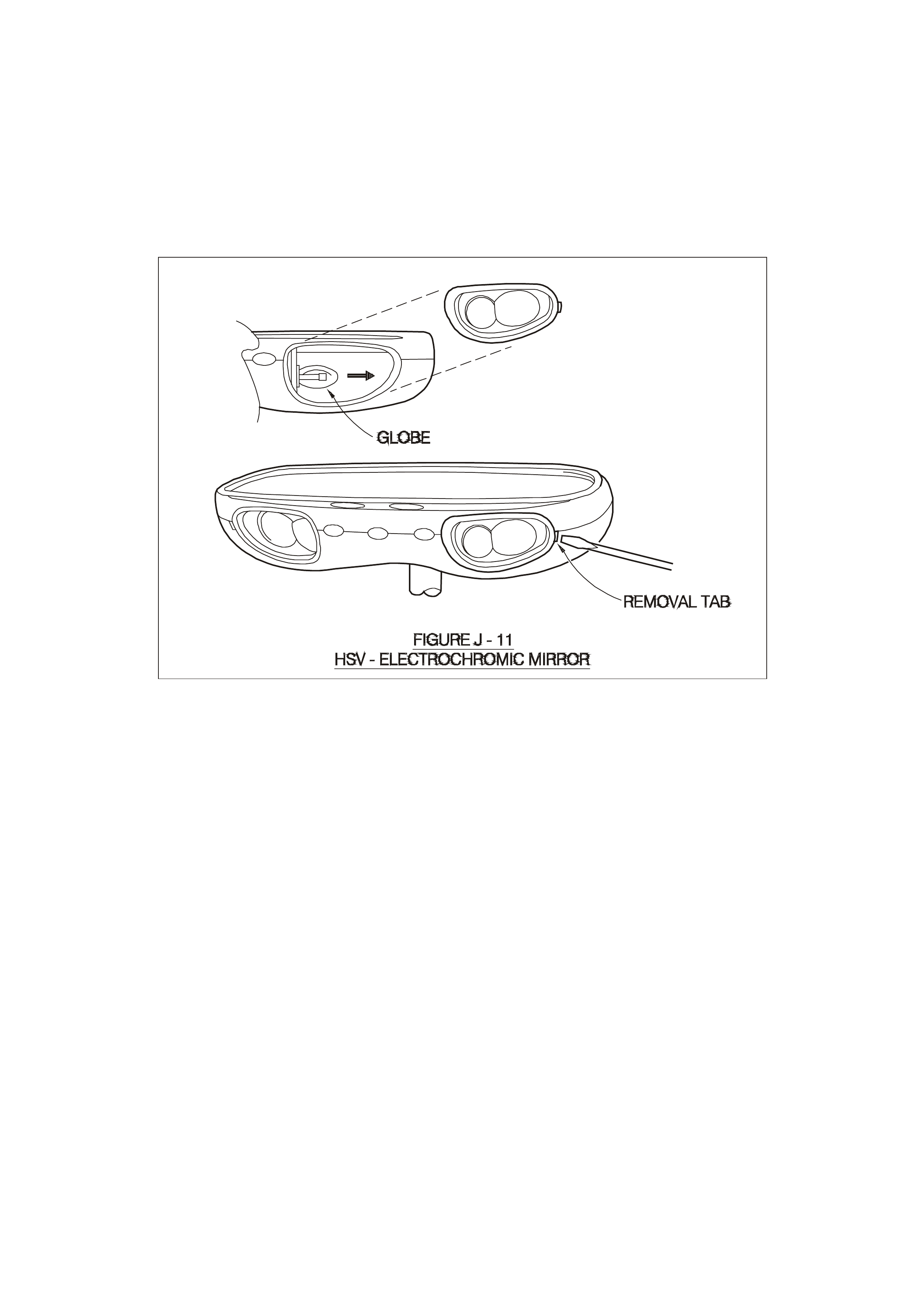
No specif ic se rvic ing of the m irror is requ ired. To r eplace m ap l ight g lobes us e a s m all scr ew dr iver to pr is e ou t th e
lens
assembly to reveal a wedge-base five watt (5.0 W) globe (see Figure J-11). Refit lens assembly by inserting the
end closest to c entre of m irror f irst - ensure lam p bulb passes through hole in side of l ens assem bly. The m irror is
fitted with a short h arnes s whic h con nects to the HS V elec trochrom ic m irror harnes s abo ve the he adlining near the
mirror: this harness runs across the headlining and down the `A’ Pillar to the main wiring harness which provides
connections to the battery, door switch, ignition, reverse lamps and ground.

8. HSV FOG LAMPS
8.1 GENERAL
HSV Fog lam ps are fitted directl y to the fr ont fasc ia of all H SV VT2 m odels ex cept XU8 ( which is fitted wit h GMHA
lamps). The HSV lam ps use a glass convex reflector to provide a wide-angle beam concentrated in a range of 30
to 40 metres in front of the lamp. The external lense incorporates a clear horizontal section .
8.2 SERVICE OPERATION
No periodic s er v icin g of the HS V l amps is r equired ho we ver , oc c asio na l r e-al ig nment ma y be necessary. Alignment
is altered b y minute adjus tments of the three m ounting s crews. F og lam ps are adjuste d to focus on a cen tral ‘HOT
SPOT ’ 5.0 centimetr es below the above gr ou nd hei ght of t he lamp ( with t he c ar level le d to normal oper a tin g h eig ht)
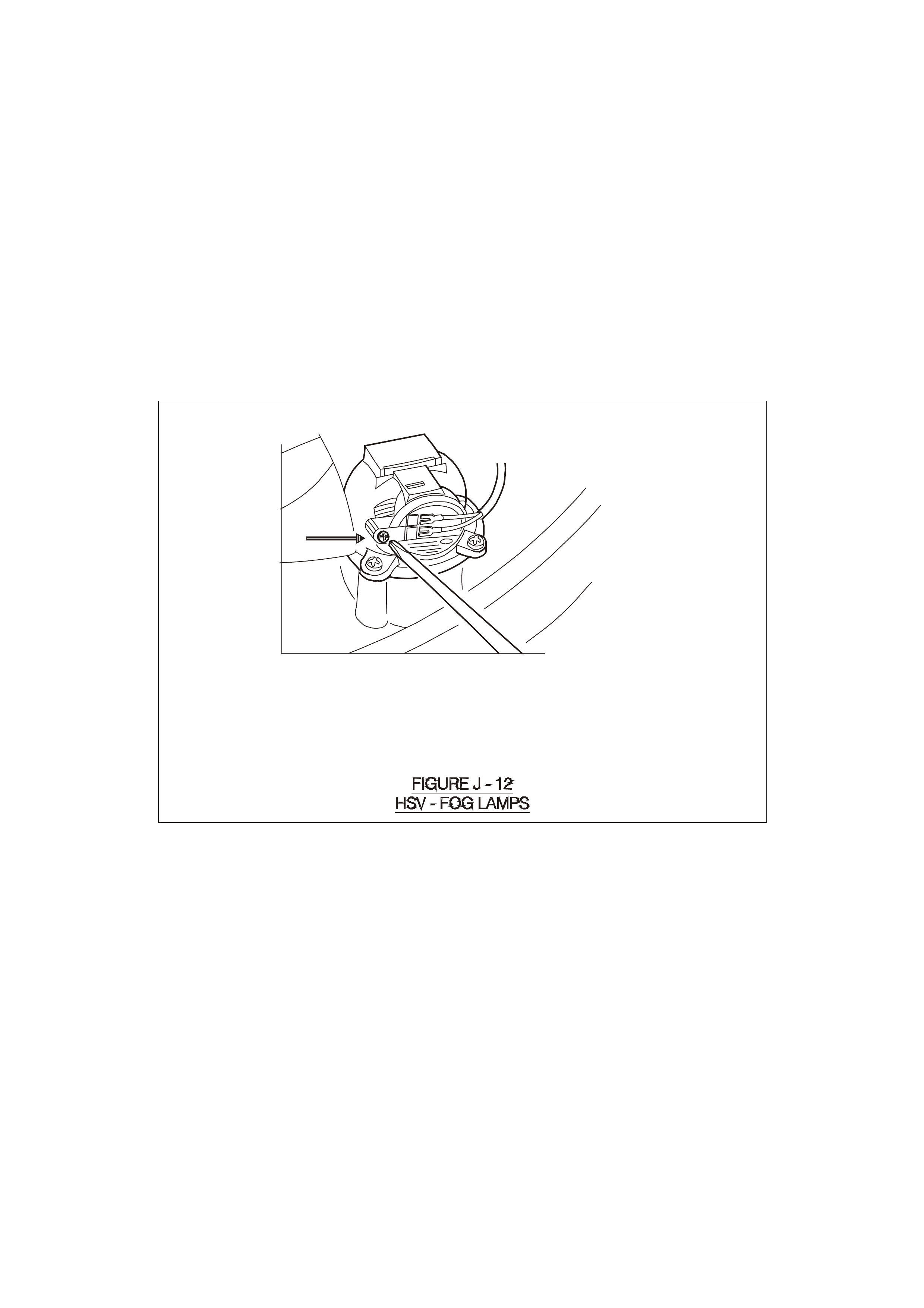
at a distance of 25 metres from the bumper bar of the vehicle. Globes may be replaced without altering the
alignment by removing a water-tight access cover on the underside of the lamp (see Figure J-12): unclip the two
spring clips which retain the globe carrier at the focal point of the reflector. Replacement fog lamps available
through HSV are identified as follows
12C-970601 LAMP FOG LEFT HAND
12C-970602 LAMP FOG RIGHT HAND
NOTE: CO NDENSAT ION MA Y APPE AR ON T HE LENS E OF T HE FO G L AMP WHEN APPRO PRIAT E A MBIENT
CONDITIONS EXIST. THIS CONDENSATION WILL CLEAR AS THE AMBIENT CONDITIONS CHANGE OR
AFTER FOUR OR FIVE MINUTES OPERATION OF THE FOG LAMPS