
Suspension Page C-1
Page C-1
Section C
Suspension
ATTENTION:
HSV vehicles are equipped with a Supplemental Restraint System (SRS). An SRS consists of seat belt pre-
tensioners (fitted to all front seats), a driver’s-side air bag, a passenger’s-side air b ag and left and right hand
side air bags. Refer to CAUTIONS, Section 12M, in Volume 12 of the Holden VY AWD Crew Cab series
Service Manual before performing any service operation on or around SRS components, the steering
mechanism or wiring. Failure to follow the CAUTIONS could result in personal injury or unnecessary SRS
system repairs.
1 Purpose...................................................................................................................................................2
2 Front Suspension...................................................................................................................................3
2.1 General Information............................................................................................................................................... 3
2.2 Service Intervals..................................................................................................................................................... 4
2.3 Service Operations ................................................................................................................................................ 5
2.4 Front Suspension Components............................................................................................................................ 6
Front Strut Detail.................................................................................................................................................... 6
Front Spring Detail................................................................................................................................................. 6
Front Stabiliser Bar Detail..................................................................................................................................... 7
3 Rear Suspension....................................................................................................................................8
3.1 General Information............................................................................................................................................... 8
3.2 Service Operations ................................................................................................................................................ 9
3.3 Rear Suspension Components........................................................................................................................... 10
Rear Spring Detail................................................................................................................................................ 10
Rear Shock Absorber Detail................................................................................................................................ 10
Rear Stabiliser Bar Detail.................................................................................................................................... 10
4 Rear Axle...............................................................................................................................................11
4.1 General Information............................................................................................................................................. 11
4.2 Service Operations .............................................................................................................................................. 12
4.3 Propeller Shaft And Universal Joints................................................................................................................. 13
4.4 Service Operations .............................................................................................................................................. 14
5 Specifications.......................................................................................................................................15
Front Suspension Service Alignment Data........................................................................................................ 15
Service Information ............................................................................................................................................. 15
Rear Suspension Service Alignment Data......................................................................................................... 16
Suspension Page C-2
Page C-2
1 Purpose
The purpose of this section is to provide information on the front and rear suspension assemblies fitted to HSV
Avalanche XUV AWD models. The information is designed to supplement the information contained in the Holden VY
AWD Crew Cab Service Manuals, and details are given where differences occur between the HSV models and standard
Holden models. A series of instruction drawings describe the design changes and indicate specific part numbers, fitting
instructions and relevant notes for vehicle servicing.
NOTE
If specific technical data on a HSV model is not
contained in this supplement, obtain data for that
model from the relevant Holden VY AWD Crew
Cab series Service Information Supplement.
References are made throughout this section to
Holden Service Manuals, to assist in providing
information for specific service operations.
When hoisting (or jacking) HSV models,
ensure that the liftin g head of the hoist lifts on
the chassis before the arm of the hoist
contacts the side-skirt

Suspension Page C-3
Page C-3
2 Front Suspension
2.1 General Information
The front suspension assembly fitted to all HSV Avalanche XUV AWD models is based on the Holden ‘MacPherson Strut’
design. The assembly consists of the front suspension crossmember cradle, lower control arms, stabiliser bar and heavy
duty strut assemblies. All HSV front suspension struts are gas pressurised. This basic assembly is then modified by
HSV to provide a suspension system more suited to the requirements of the HSV vehicle.


Suspension Page C-5
Page C-5
2.3 Service Operations
Service front suspension assemblies fitted to HSV models in accordance with the relevant Holden VY AWD Crew Cab
Series Service Information. Additional service requirements for specific HSV suspension assemblies are detailed in
succeeding paragraphs.
SAFETY AND CAUTIONARY NOTE FOR
VEHICLES EQUIPPED WITH ABS
Whenever any component that forms a part of the ABS is disturbed, it is vital that the complete ABS system is checked.
Refer to Section 5B ABS & ETC of the Holden VY AWD Crew Cab Service Information.
Suspension Page C-6
Page C-6
2.4 Front Suspension Components
The following components are fitted to front suspension assemblies as indicated:
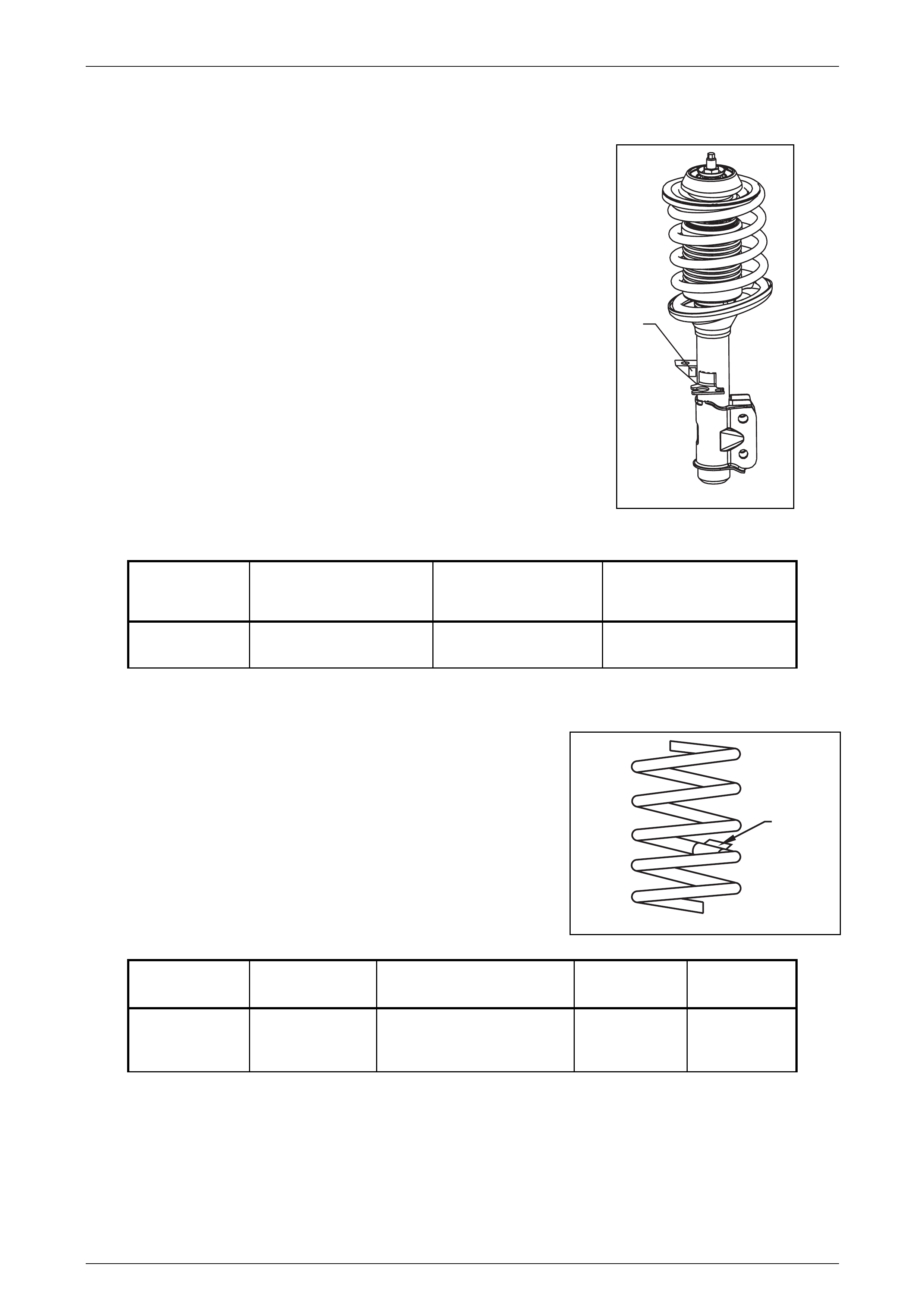
Front Strut Detail
Type: Twin Tube Hydraulic, gas pressurised
Piston: 30mm
Identification of the front strut assemblies fitted to a particular vehicle can be
achieved by cross referencing either the stamped in part number (see strut
lower tube), or production identification tag (1) with the table below.
Model Part Number
LH Strut
Part Number
RH Strut
Production ID Code
Avalanche XUV
Crew cab 03F – 032705 03F – 032706 AY2
Front Spring Detail
Identification of the front spring fitted to a particular vehicle can be achieved
by cross-referencing the label details (1) with the table below.
Model Free Length
(mm) Spring Type and Rate Part Number Production ID
Code
Avalanche XUV
Crew cab 438 Variable 24– 31 N/mm
(50266110 N @ 234 mm)
92112583 AC
1
1
Suspension Page C-7
Page C-7
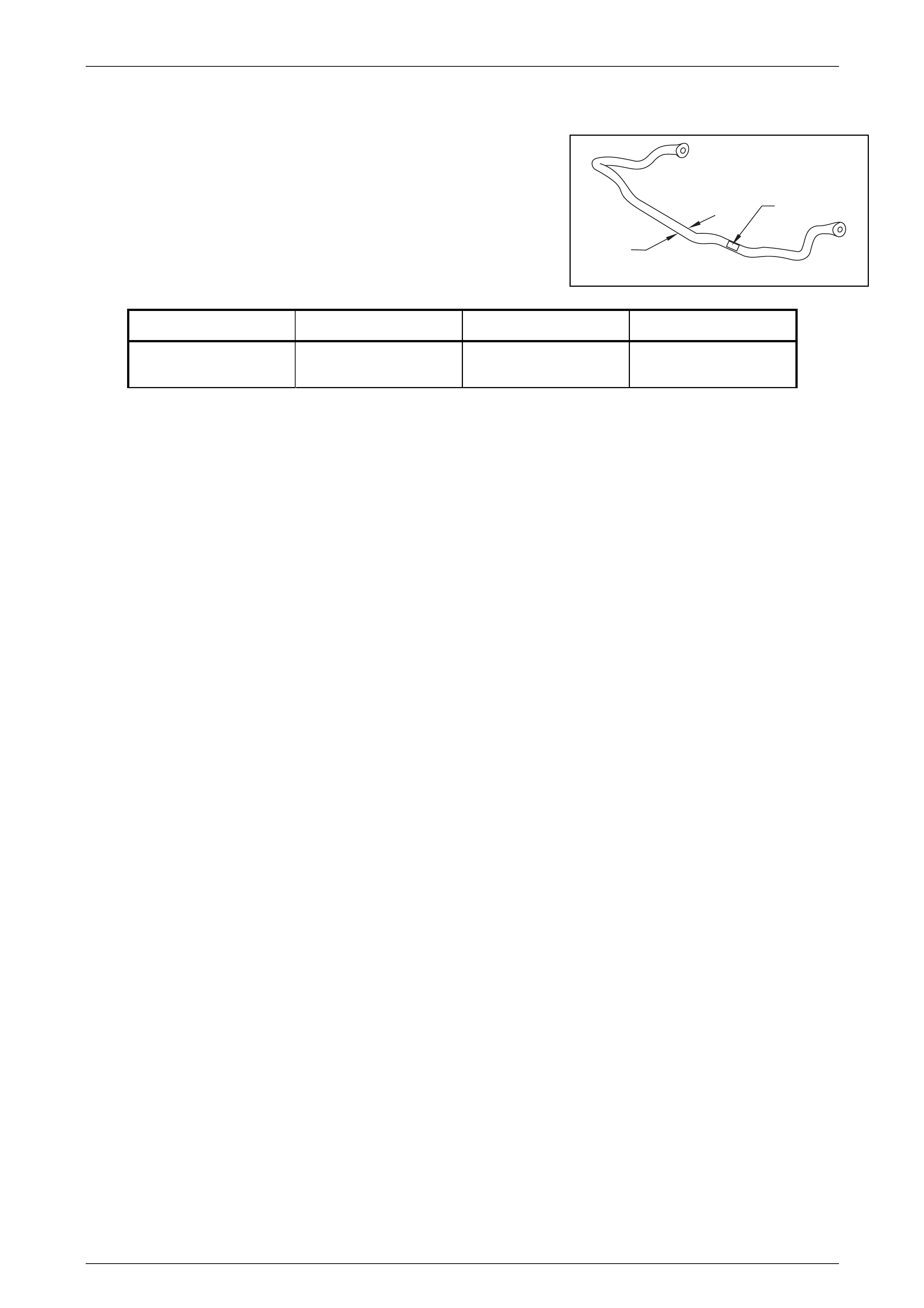
Front Stabiliser Bar Detail
Identification of the front stabiliser shaft fitted to a particular vehicle can be
achieved by cross-referencing the two-digit production identification tag (1)
with the table below.
The table also provides the shaft diameter (2).
Model Diameter (mm) Part Number Production ID Code
Avalanche XUV Crew
cab 28 92164581 AC
1
2

Suspension Page C-8
Page C-8
3 Rear Suspension
3.1 General Information
Rear suspension assemblies fitted to HSV Avalanche XUV AWD models are the same as that fitted to 2003 VY Series
Regular Cab models except for the following :
Spacers between the rear axle housing and the leaf springs have been removed, to provide an increased body
clearance.
The rear stabiliser bar has been removed.
The load proportioning valve has been removed, as it is no longer required with the four chanel ABS-TC system.
The rear springs are carry over from the 2003 VY Regular Cab Models(2WD)
The rear shock absorbers are HSV Touring spec.
For service information on the rear suspension operations on this vehicle refer to Section 4A Rear Suspension, in the
2003 VY Series, Regular Cab Service Information

Suspension Page C-9
Page C-9
3.2 Service Operations
Service Operations and Service Intervals for HSV Rear Suspension assemblies are the same as those detailed in the
relevant Holden VY AWD Crew Cab Service Manual except when detailed otherwise in this supplement.
Suspension Page C-10
Page C-10
3.3 Rear Suspension Components
The following HSV components are fitted to rear suspension assemblies as indicated:
Rear Spring Detail
Model Free Length
(mm) Spring Type and Rate Part Number Production ID
Code
Avalanche XUV
Crew cab N/A Variable (32 – 77 N/mm)
Semi elliptical
3 Primary Leaves
1 Secondary Leaf
92168407 LF
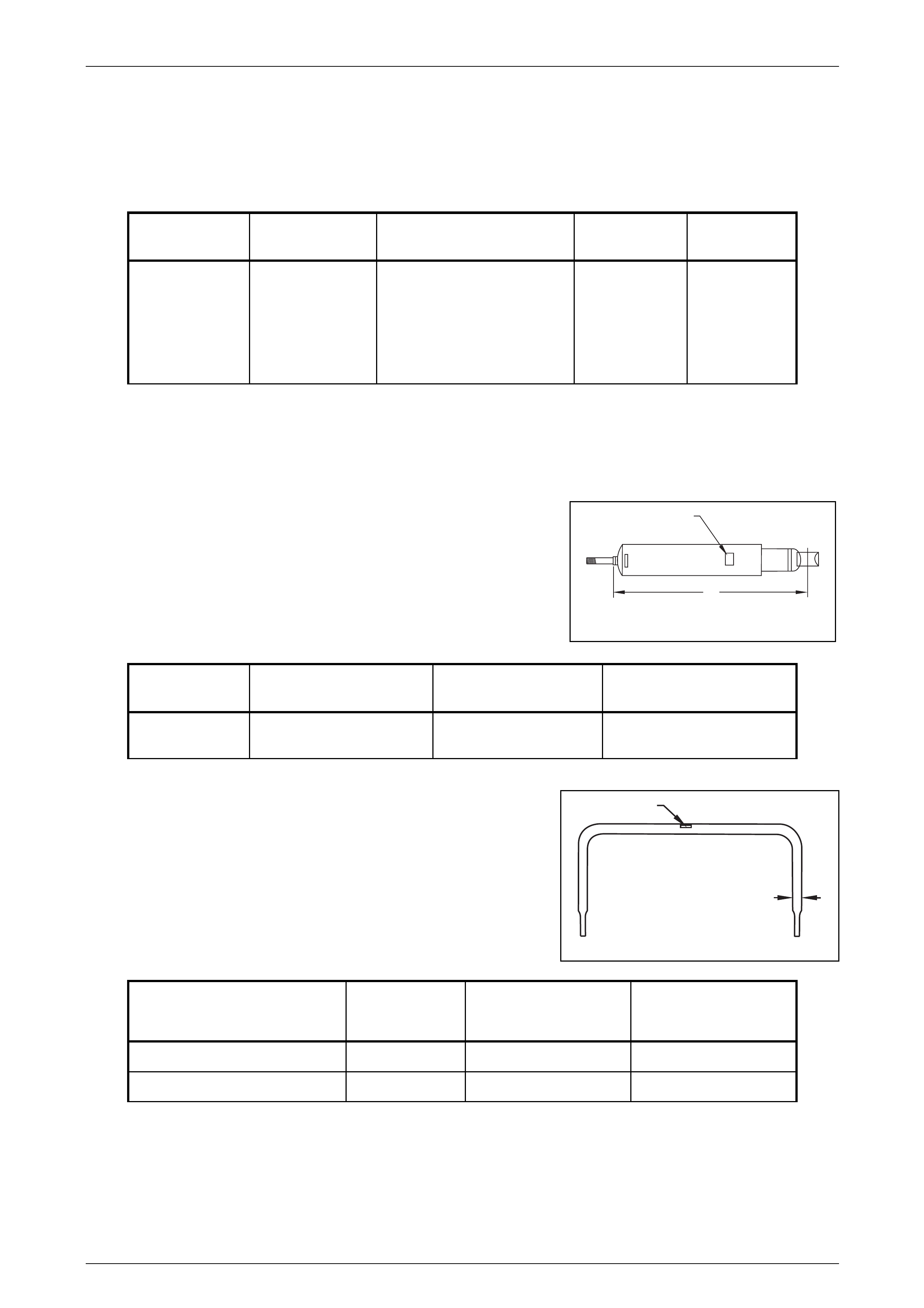
Rear Shock Absorber Detail
Type: Twin Tube Hydraulic, gas pressurised
Identification of the rear shock absorber fitted to a particular vehicle can be
achieved by cross referencing either the stamped in part number (see lower
damper tube), or production identification code (1) with the table below.
Model Nominal Extended
Length (A) Part Number Production ID Code
Avalanche XUV
Crew cab 548 04E - 033101 CY2
Rear Stabiliser Bar Detail
Identification of the rear stabiliser shaft fitted to a particular vehicle can be
achieved by cross-referencing the two-digit production identification tag (1)
with the table below.
The table also provides the shaft diameter (2).
Model Diameter
(mm)
Part Number Production ID Code
AvalancheAWDWagon 16 92048231 FK
Avalanche XUV Crew cab _ N/A _
A
1
1
2

Suspension Page C-11
Page C-11
4 Rear Axle
4.1 General Information
The Rear Axle fitted to HSV Avalanche AWD models is the same as the Holden Rear Axle. The information in this
section is designed to supplement the information contained in the Holden Adventra AWD service information and
details are given where differences occur between the HSV models and standard Holden models.

Suspension Page C-12
Page C-12
4.2 Service Operations
Service Operations and Service Intervals for HSV Rear Axle assemblies are the same as those detailed in the relevant
Holden Adventra AWD Service Manual except when detailed otherwise in this supplement.

Suspension Page C-13
Page C-13
4.3 Propeller Shaft And Universal Joints
HSV Avalanche models use standard GMHA propeller and drive shafts.

Suspension Page C-14
Page C-14
4.4 Service Operations
Service procedures for propeller shaft assemblies fitted to HSV models are the same as those described in the Holden
Adventra AWD series Service Manual.
Suspension Page C-15
Page C-15
5 Specifications
Front Suspension Service Alignment Data
The tyre life of high performance low-profile tyres fitted to HSV Avalanche AWD vehicles is very sensitive to the toe-in
setting of the front suspension. It is crucial therefore, that care is taken to set the toe-in accurately to the correct
specification.
FRONT WHEEL ALIGNMENT AT CURB WEIGHT
Wheel Alignment Angle Specifications
Camber - 0°30´ ± 0º15´
Caster 8º30´ ± 1º15´
Toe – in Degrees Total 0º10´ ± 0º10´
Degrees per Wheel 0º5´± 0º5´
Toe – out on Turns 1º42´@ 20º turn angle ± 1º 30´
Steering Axis Inclination Angle 13º18´ ± 1º30´
Included Angle 13º06´ ± 1º30´
Service Information
The adjusting values for camber, caster and toe in must remain within the tolerances specified. The difference between
left and right must not exceed the following.
CASTER..................................................................................................0º36´
CAMBER.................................................................................................0º15´
TOE – IN .................................................................................................0º10´
The specifications listed are the nominal value with acceptable variance from this central point. Where possible an
attempt should always be made to achieve the nominal settings when adjusting.
Front wheel camber alters as a function of front suspension height.
Camber adjusting bolt. After loosening both lower strut to steering knuckle bolts and nuts, adjust camber by turning the
adjusting bolt clockwise to decrease negative camber and anti clockwise to increase negative camber. After adjustment,
both lower strut to steering knuckle bolts and nuts MUST be replaced with new parts and tightened to the recommended
torque setting.
The rear wheel alignment should be checked and corrected if necessary (refer to Section 4A Rear Suspension, in the MY
2004 AWD Wagon Service Information) before checking front wheel alignment.
Fuel Mass with Full Tank = 56kg
Suspension Page C-16
Page C-16
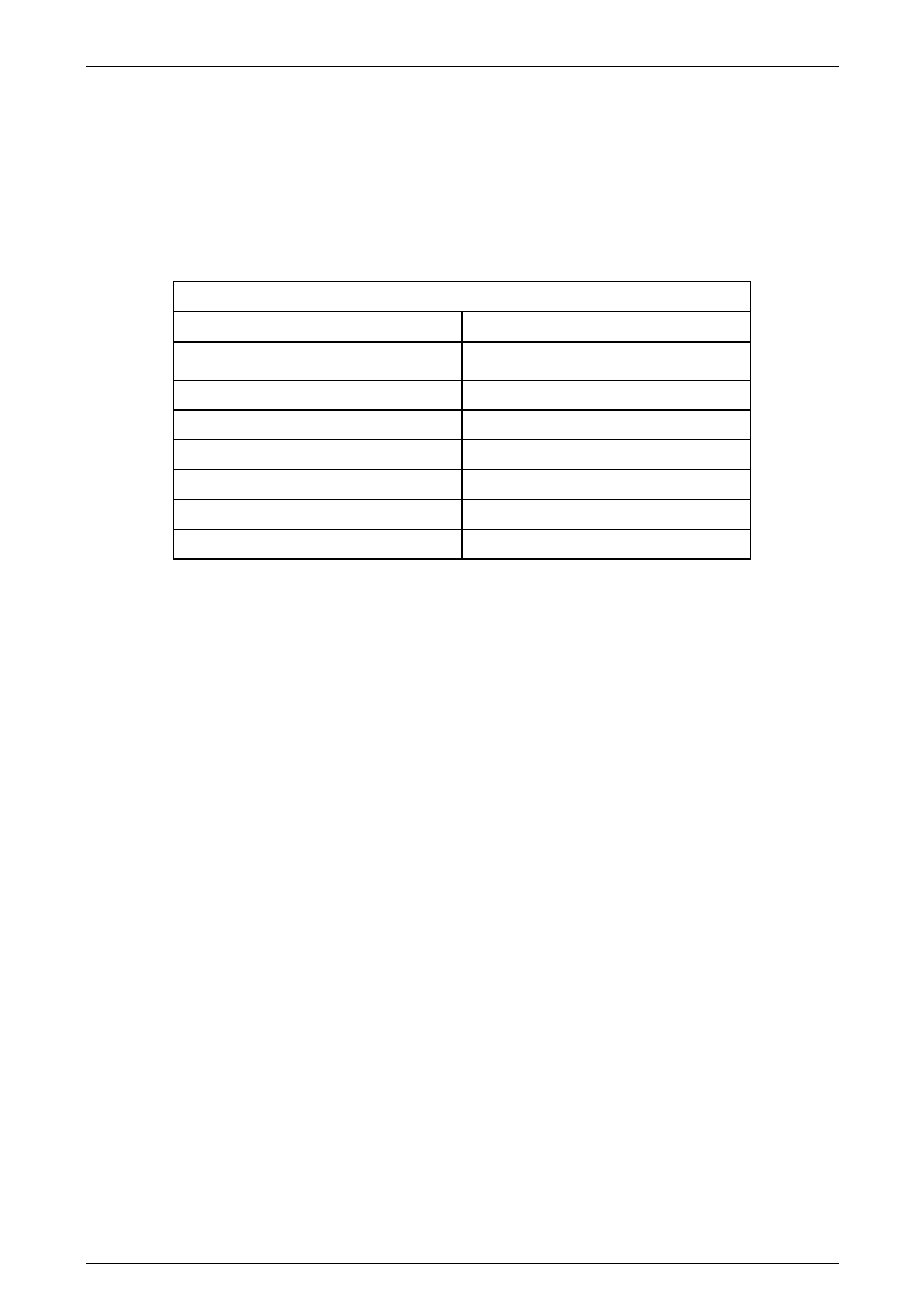
Rear Suspension Service Alignment Data
The tyre life of high performance low-profile tyres fitted to HSV Avalanche XUV AWD vehicles is very sensitive to the toe-
in setting of the front suspension. It is crucial therefore, that care is taken to set the toe-in accurately to the correct
specification.
Model Rear Wheel Camber
(Tolerance)
Toe Degrees per Wheel
(Variation Side to side)
Avalanche AWD Wagon Nominal – 0030’
(Range –1018’ to – 002’)
0008’ to 0022’
(0010’ Maximum)
Avalanche XUV Crew cab N/A * N/A *
Dimensions shown are for vehicle at curb height, ie. Vehicle ready to drive with all fluids at the
recommended levels, the fuel tank full and without the driver, passengers or luggage.
Positive Toe figures indicate that “ Toe in” is required.
Refer to section 2.7 “Rear Wheel Alignment Checking” under MY 2004 VY Series AWD WAGON of
the Service information pack, for specific details.
* The live rear axle fitted to the Avalanche XUV is non adjustable.
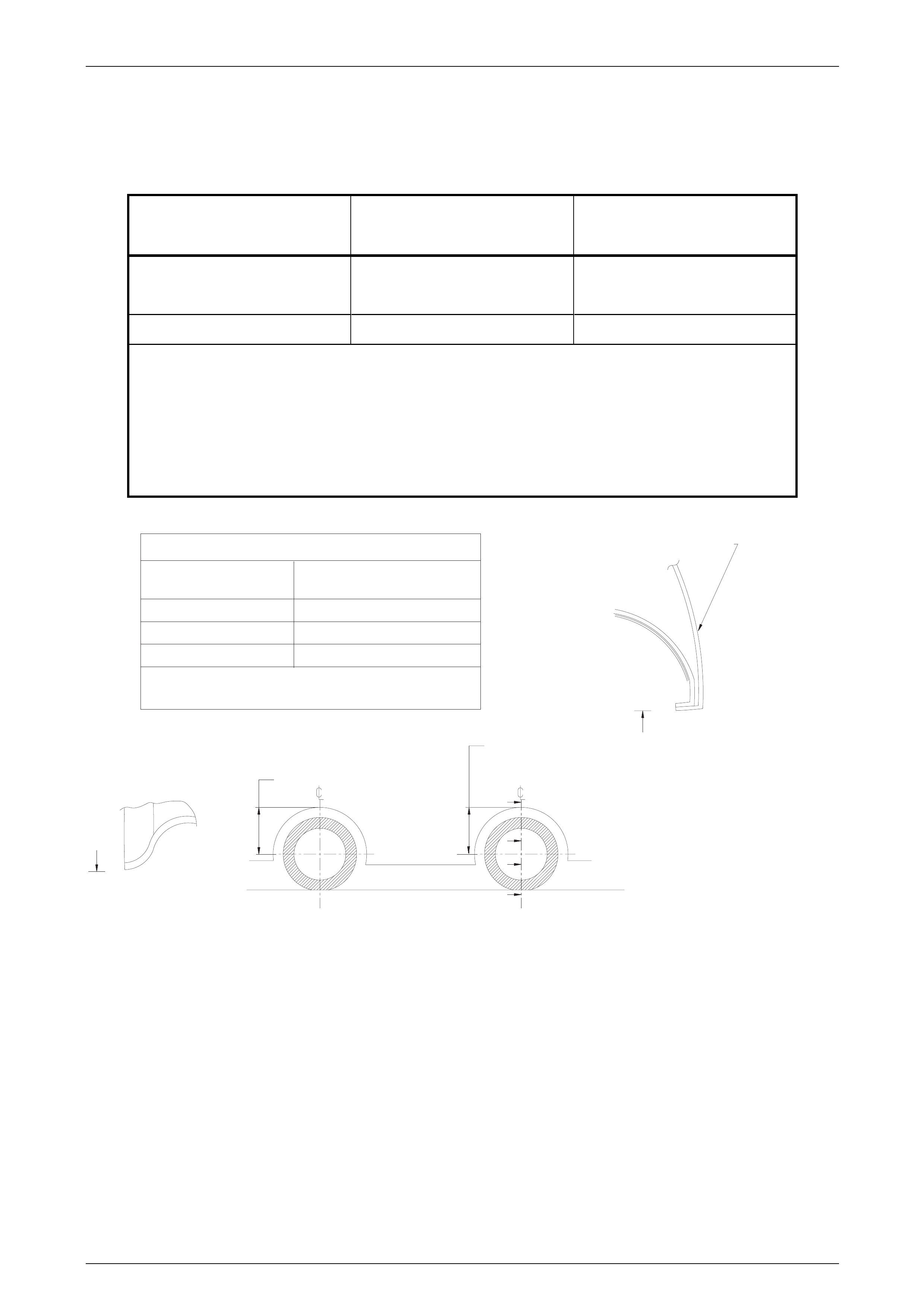
MEASURE SUSPENSION HEIGHTMEASURE SUSPENSION HEIGHT
FROM UNDERSIDE OF WHEEL ARCHFROM UNDERSIDE OF WHEEL ARCH
TO LOWER POINT OF WHEEL RIMTO LOWER POINT OF WHEEL RIM
B
B
A
A
SECTION A-A
SIDE PANEL OUTERSIDE PANEL OUTER
SECTION B-BSECTION B-B
MODEL VZ XUV
MODELS
VZ XUV
MODELS
WHEEL SIZE
FRONT
REAR
VEHICLE SUSPENSION HEIGHT AT KERB WEIGHTVEHICLE SUSPENSION HEIGHT AT KERB WEIGHT
Suspension Height Measurements in mm.Suspension Height Measurements in mm.
Kerb weight = Base weight + full tank of fuelKerb weight = Base weight + full tank of fuel
417±5417 ± 5
425±5425 ± 5
18"X8"18" X 8"
FRONT SUSPENSION HEIGHTFRONT SUSPENSION HEIGHT
REAR SUPSPENSION HEIGHTREAR SUPSPENSION HEIGHT