
Body Page B–1
Page B–1
Section B
Body
ATTENTION
Before performing any Service Operation or other procedure described in this Section, refer to Section 00
CAUTIONS AND NOTES for correct workshop practices with regard to safety and/or property damage.
1 Purpose................................................................................................................................................... 3
2 General Information............................................................................................................................... 4
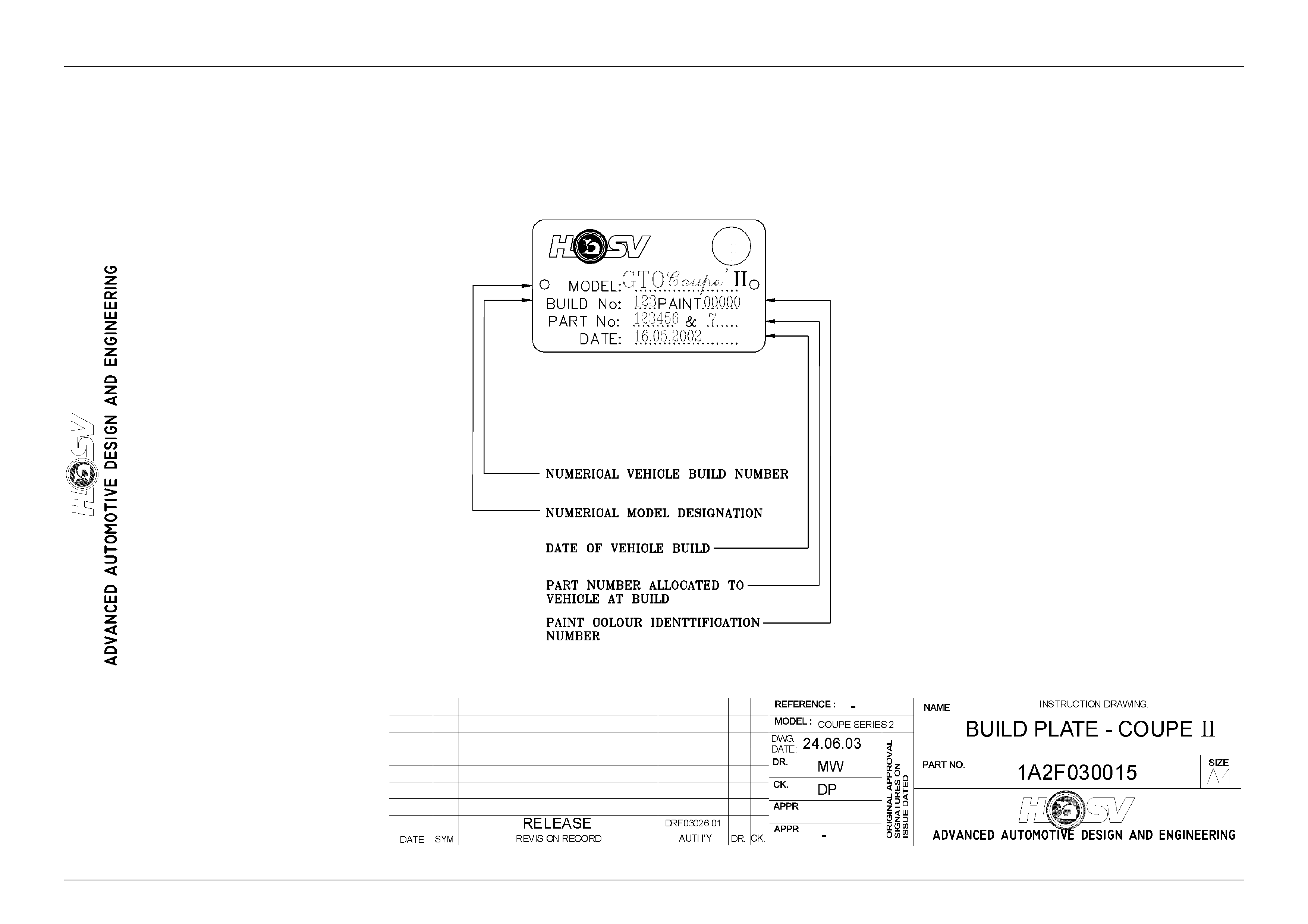
2.1 Build Plate ...............................................................................................................................................................5
3 Seats ....................................................................................................................................................... 7
4 Body Ornamentation ........................................................................................................................... 10
4.1 GTO Coupe Series 2.............................................................................................................................................11
4.2 GTS Coupe Series 2.............................................................................................................................................13
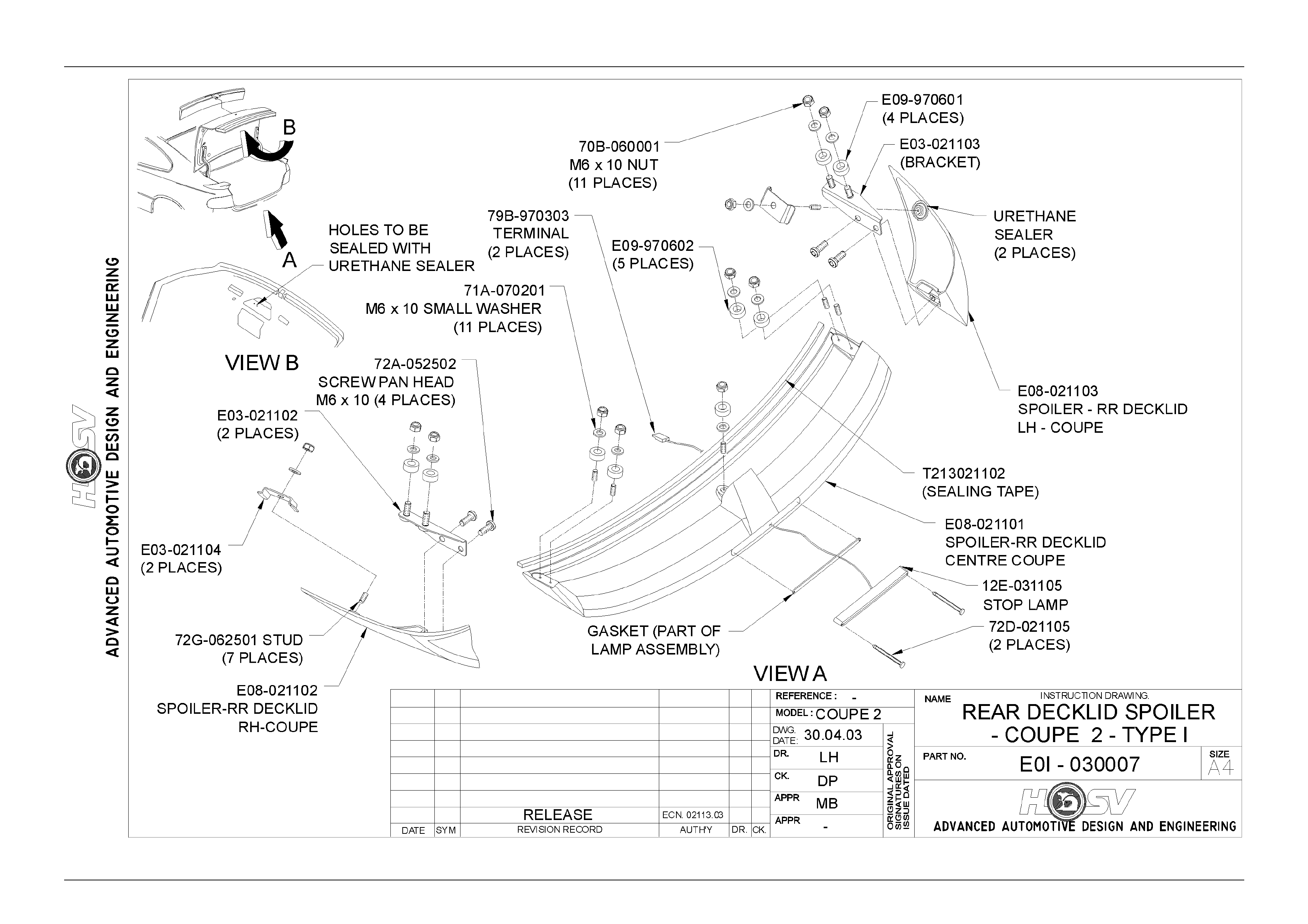
5 Coupe Rear Spoiler – Type 1.............................................................................................................. 27
5.1 Service Operations...............................................................................................................................................27
Spoiler Ends Removal .........................................................................................................................................27
Spoiler Ends Installation......................................................................................................................................28
Spoiler Centre Section Removal.........................................................................................................................28
Spoiler Centre Section Installation.....................................................................................................................28
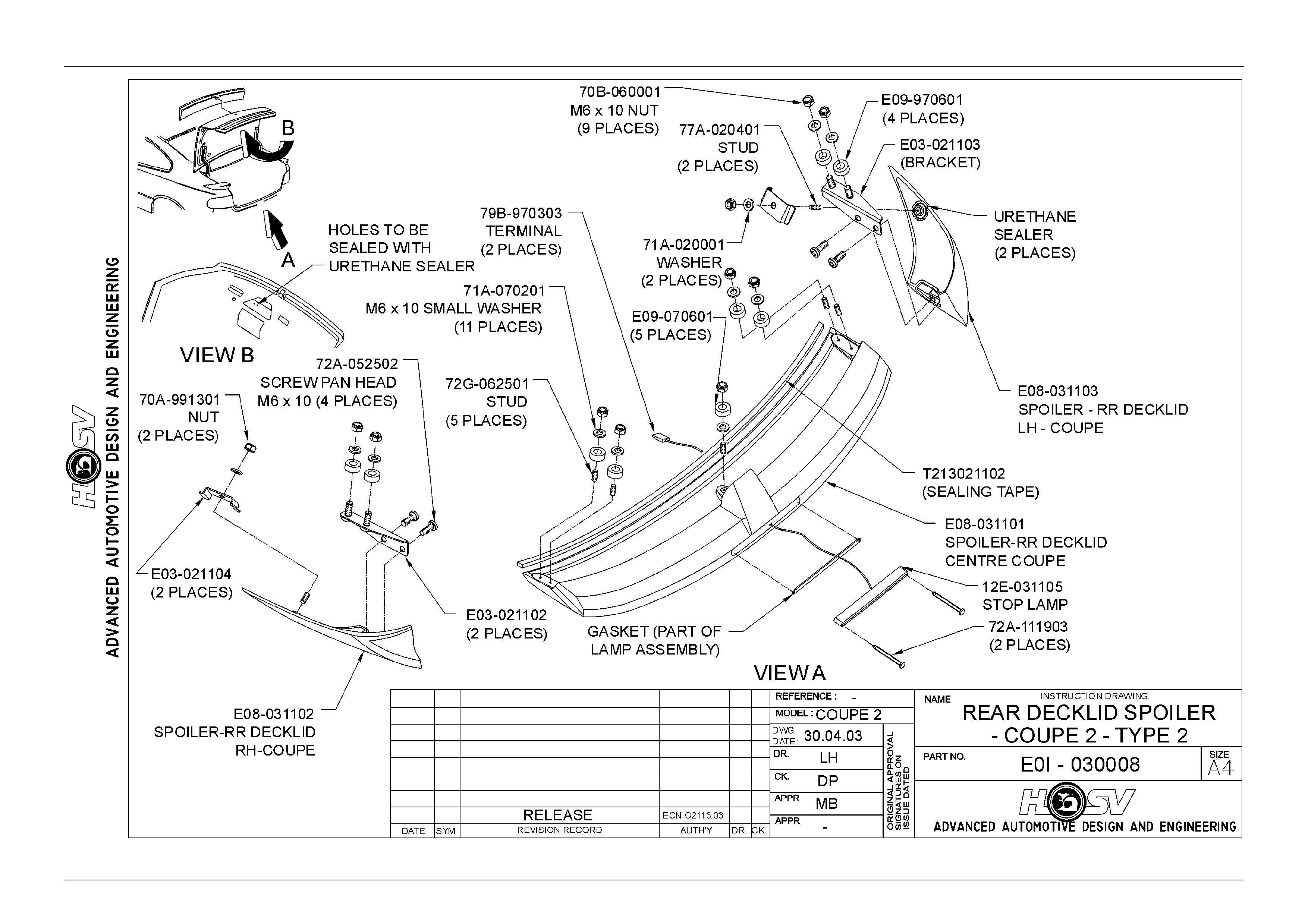
6 Coupe Rear Spoiler – Type 2.............................................................................................................. 30
6.1 Service Operations...............................................................................................................................................30
Spoiler Ends Removal .........................................................................................................................................30
Spoiler Ends Installation......................................................................................................................................30
Spoiler Centre Section Removal.........................................................................................................................31
Spoiler Centre Section Installation.....................................................................................................................31
7 Servicing the HSV Coupe Rear Spoiler. ............................................................................................ 32
7.1 Servicing Coupe Rear Spoilers – Undamaged body panels.............................................................................32
Centre Spoiler.......................................................................................................................................................32
Outer Spoilers.......................................................................................................................................................32
Attaching Parts.....................................................................................................................................................32
Sealing ..................................................................................................................................................................32
General Precaution ..............................................................................................................................................32
7.2 Servicing HSV Coupe Rear Spoilers – Where Service Replacement Body Panels are Installed...................33
To locate Attaching Holes. ..................................................................................................................................33
Alignment Tape. ...................................................................................................................................................33
Locating Attaching Holes....................................................................................................................................33
Marking Locating Holes on Body Panels...........................................................................................................33
Drilling Attaching Holes.......................................................................................................................................33
Drilling Wiring Hole..............................................................................................................................................33
Spoiler Re-Assembly. ..........................................................................................................................................34
Attaching Hole Location Check. .........................................................................................................................34
Attaching Hole Size..............................................................................................................................................34
Spoiler Sides.........................................................................................................................................................34
Side Spoiler Front Attaching Hole......................................................................................................................34
Upper Attaching Hole...........................................................................................................................................34
General Precaution. .............................................................................................................................................34

Body Page B–2
Page B–2
8 Roof Spoiler.......................................................................................................................................... 39
8.1 Service Operations...............................................................................................................................................39
Roof Spoiler Removal..........................................................................................................................................39
Roof Spoiler Installation......................................................................................................................................39

Body Page B–3
Page B–3
1 Purpose
The purpose of this section is to provide information on the body and body components fitted to HSV GTO & GTS Coupe
Series 2 vehicles. The information is designed to supplement the information contained in the Holden V2 Coupe Series
Service Information, and details are given where differences occur between the HSV models and standard Holden
models. A series of instruction drawings describe the design changes and indicate specific part numbers, fitting
instructions and relevant notes for vehicle servicing.
NOTE
If specific technical data on a HSV model is not
contained in this supplement, obtain data for that
model from the relevant Holden V2 Coupe Series
Service Information. References are made
throughout this section to Holden Service
Information, to assist in providing information for
specific serv ice operati ons .
When hoisting (or jacking) HSV models,
ensure that the lifting head of the hoist lifts on
the chassis before the arm of the hoist
contacts the side-skirt

Body Page B–4
Page B–4
2 General Information
The HSV GTO and GTS Series 2 Coupe is a two-door variant of the HSV VY Series 1 Clubsport Model. The HSV GTO
and GTS Series 2 Coupe retains the same track and wheelbase as the HSV VY Series I Clubsport and the major exterior
body sheetmetal panels carry over from the Holden V2 Series Models. HSV GTO and GTS models are equipped with
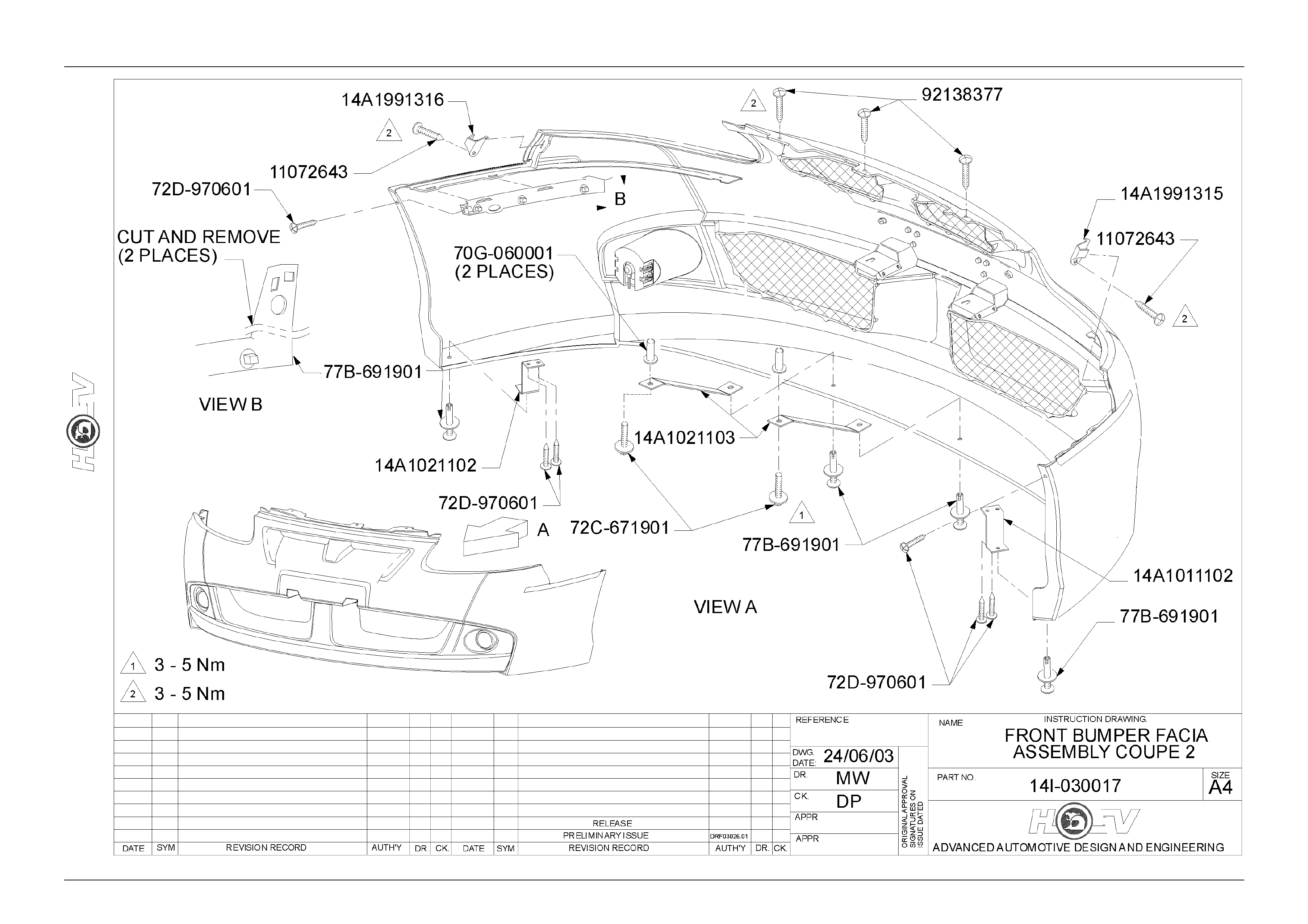
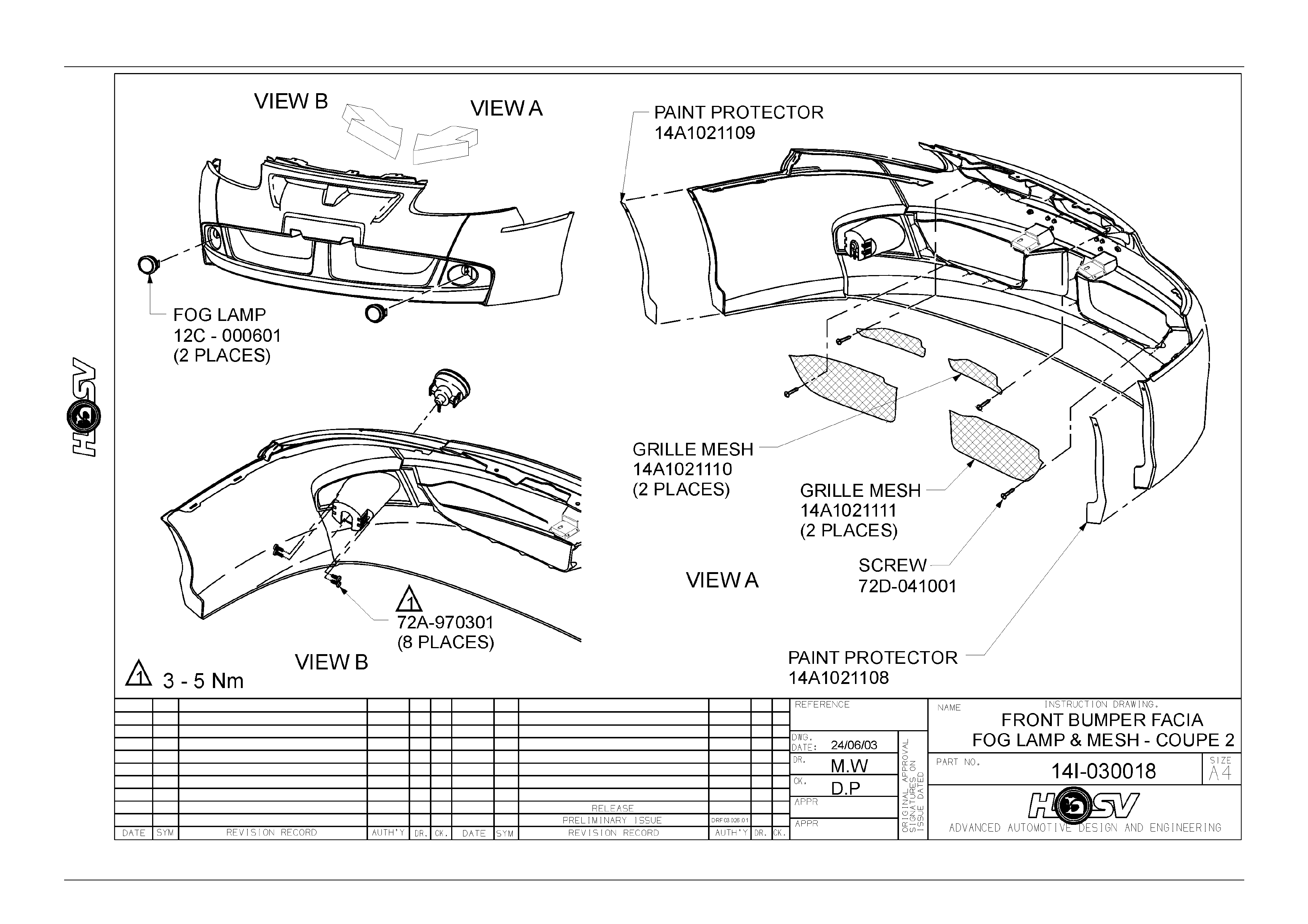
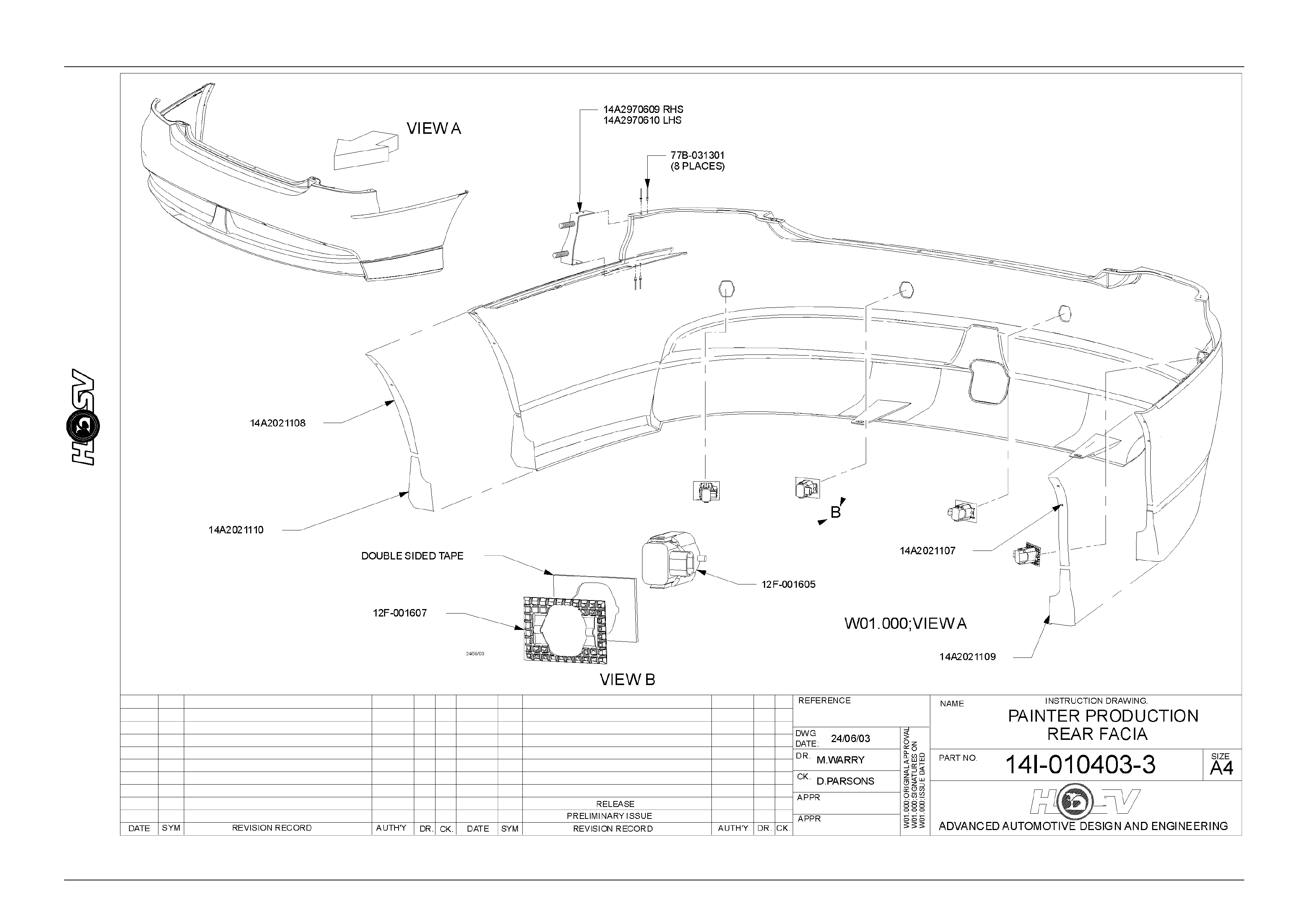
unique Body Side Skirts, 3-piece Rear Spoiler, Roof Spoiler, Front Bumper Bar Facia and Rear Bumper Bar Facia.
For all body alignment dimensions refer to Section 1A2 Body Dimensions of the Holden V2 Coupe Series Models
Service Information.

Body Page B–6
Page B–6

Body Page B–7
Page B–7
3 Seats
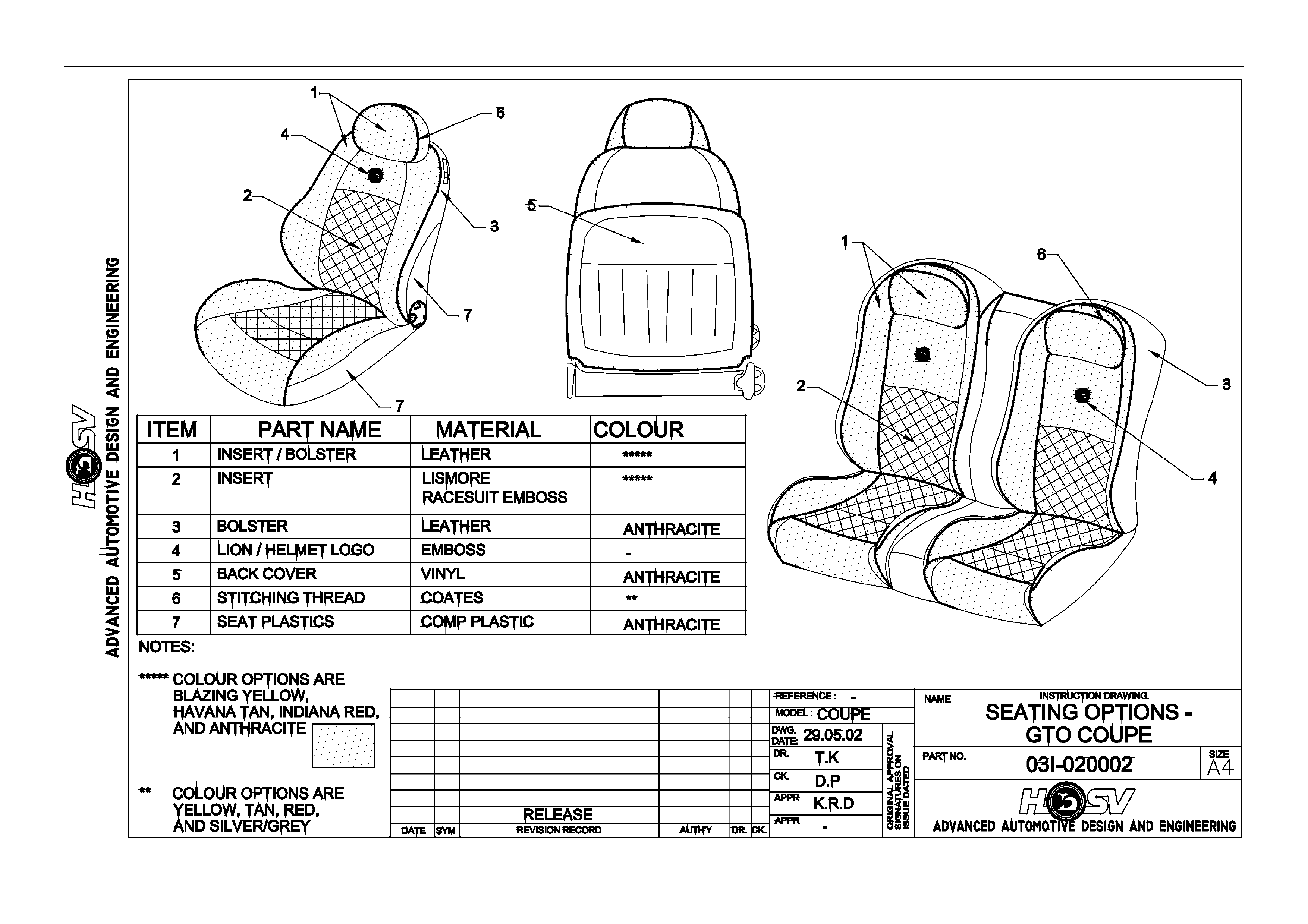
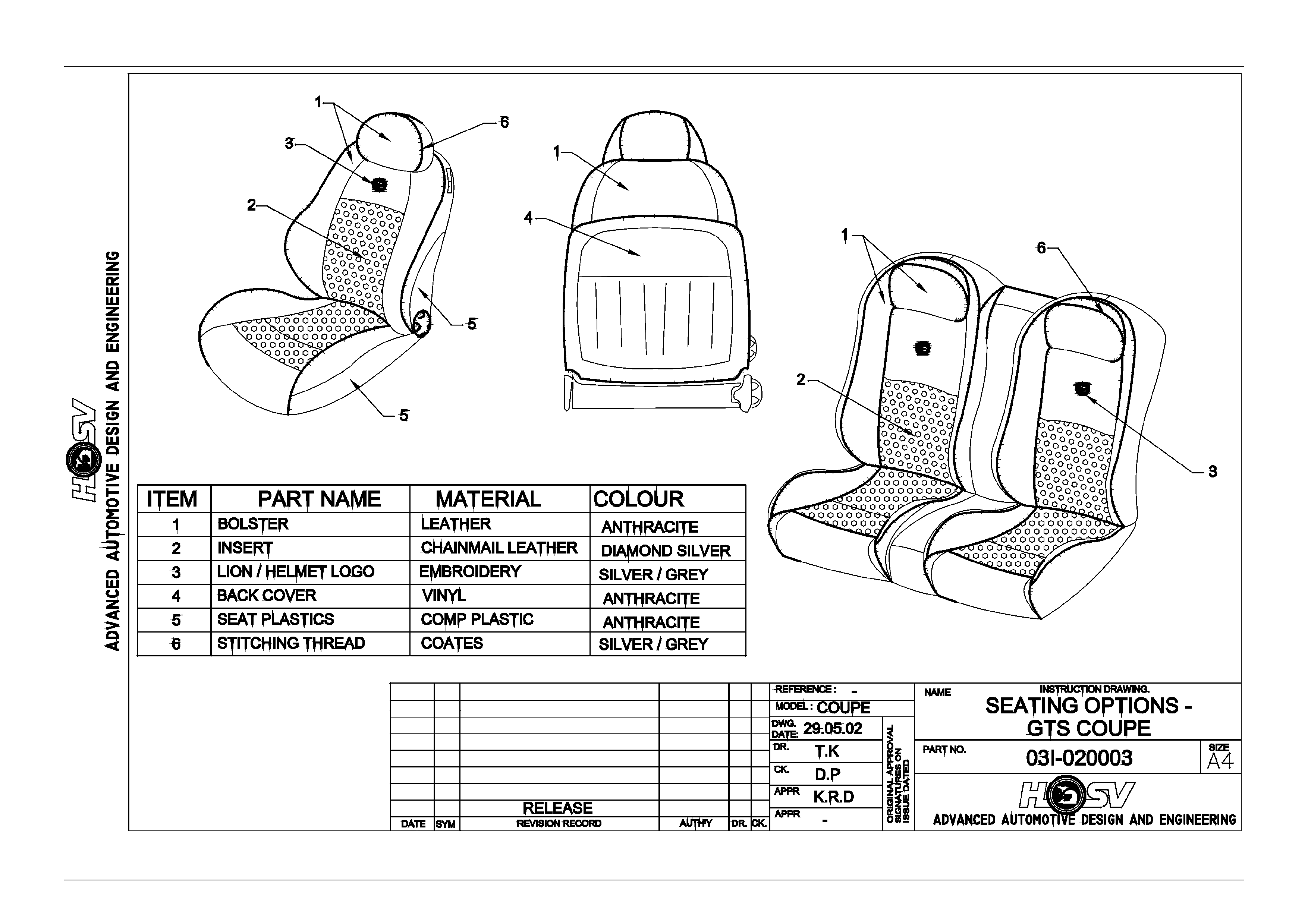
HSV GTO & GTS Coupe models are fitted with exclusive seat designs. The GTO and GTS seats (shown for identification
purposes in Drawings 03I-020002 and 03I-020003) have specific seats covered in model-specific trim material. A full range
of replacement parts is available for each specific HSV seat item.
Body Page B–8
Page B–8
Body Page B–9
Page B–9

Body Page B–10
Page B–10
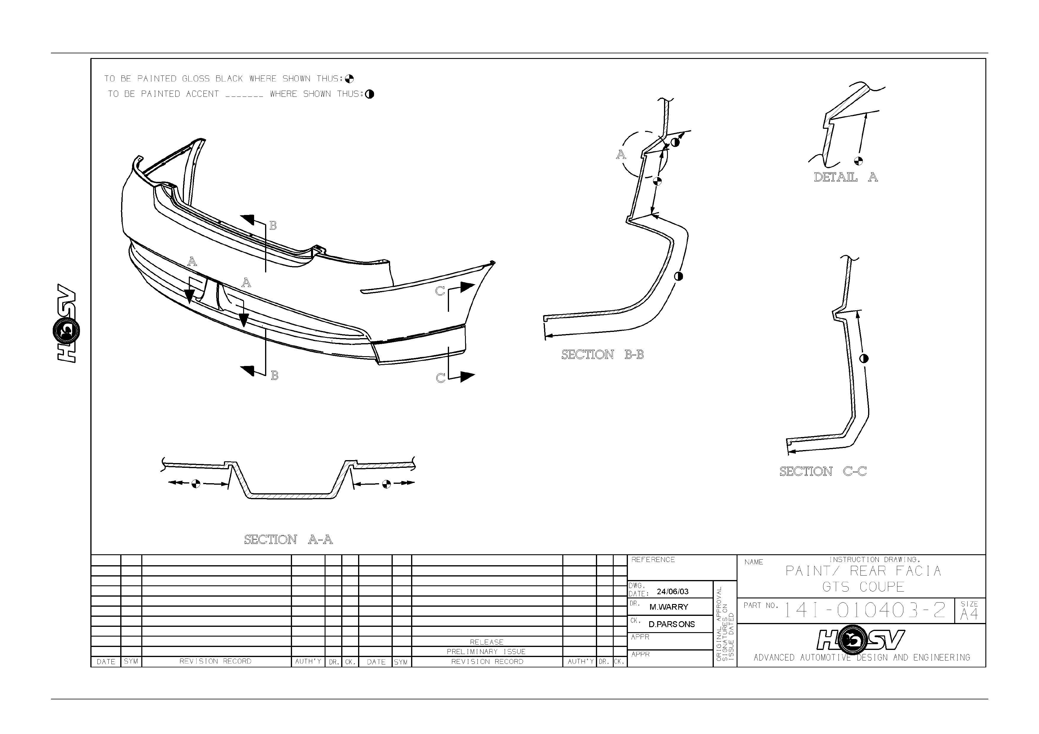
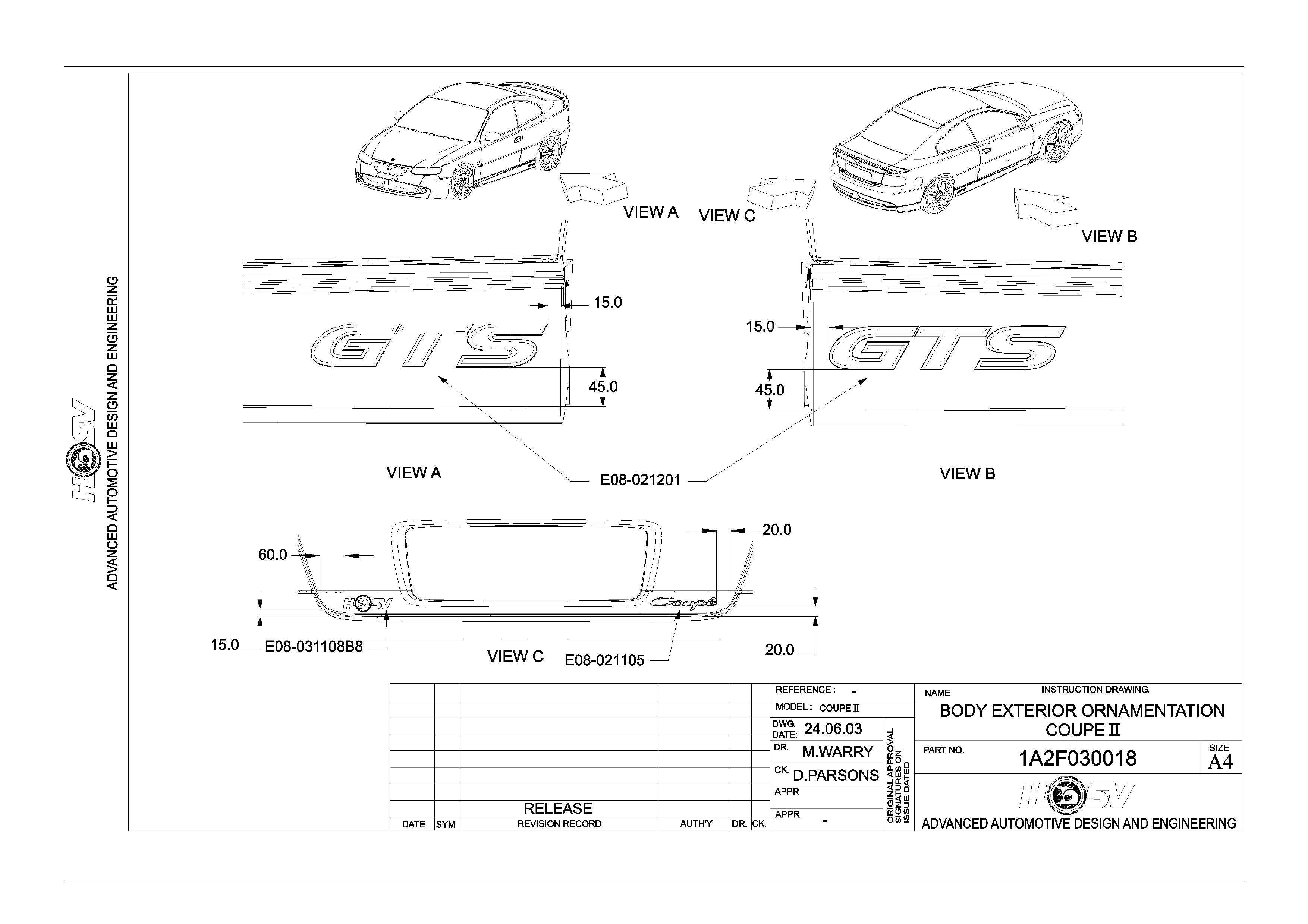
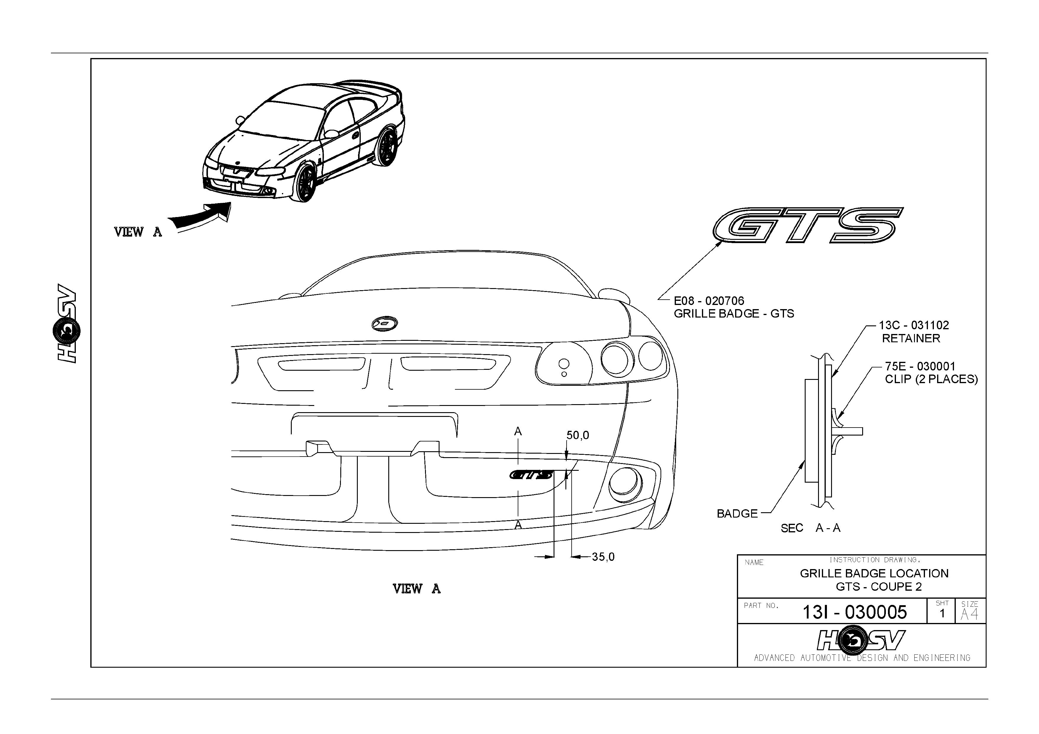
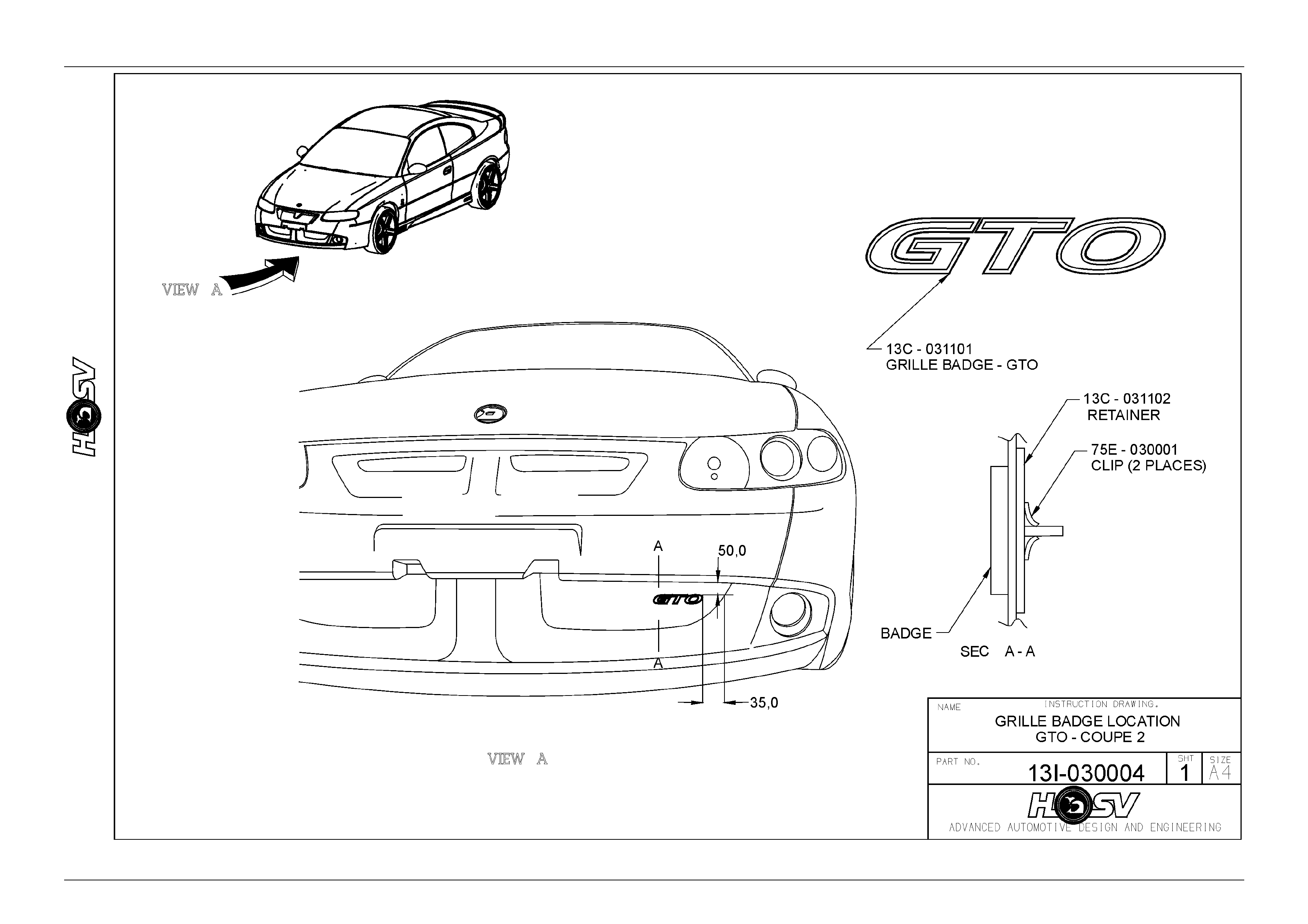
4 Body Ornamentation
HSV models are fitted with HSV specific decals, and badges to identify each model and power train option. The exclusive
HSV ornamentation is positioned in exact locations on each HSV model. The ornamentation for each model is specified
by part number in this section. Accurate dimensions are also provided to assist with the replacement of these parts.

Body Page B–11
Page B–11
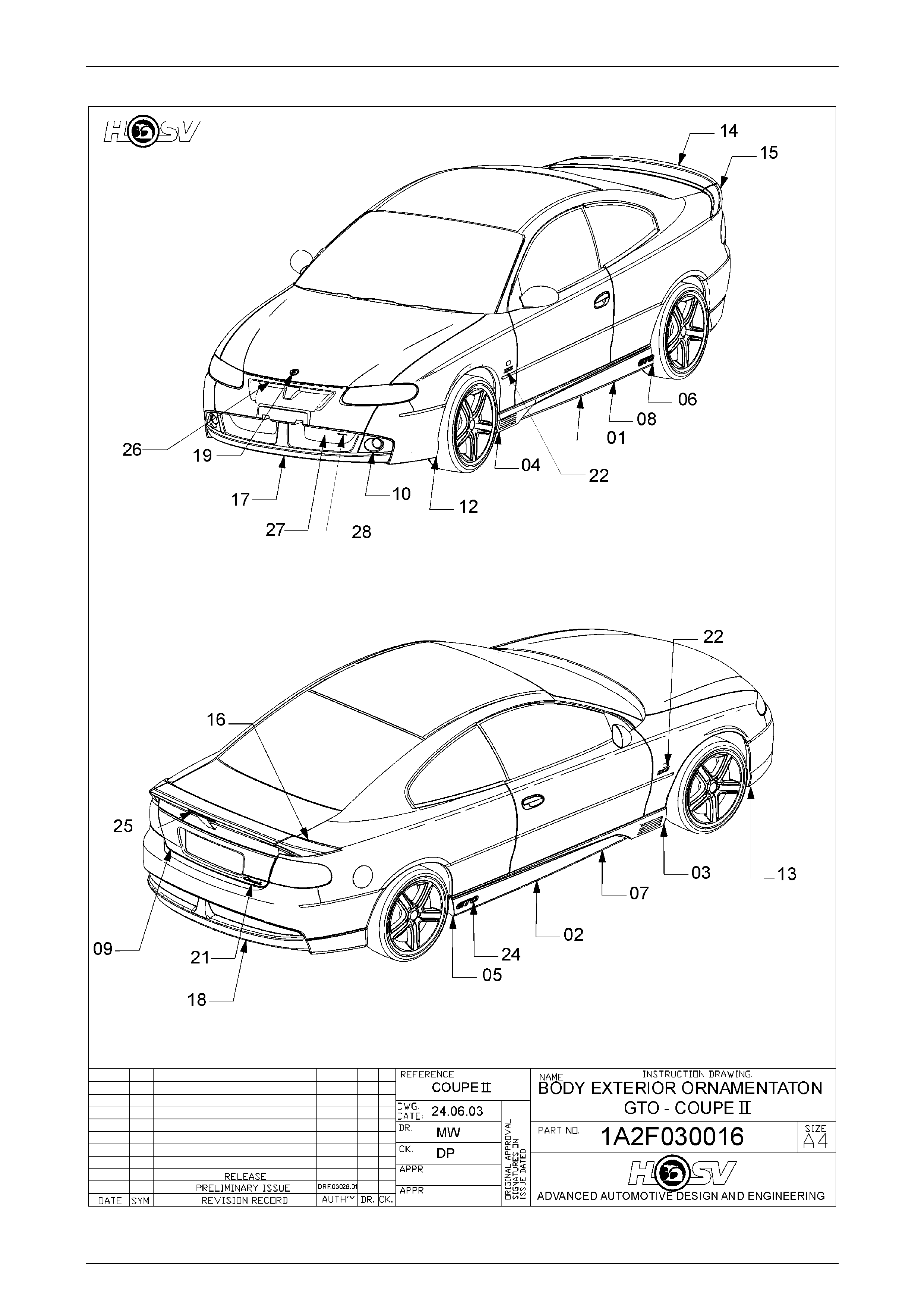
4.1 GTO Coupe Series 2
CONTENTS OF BODY STYLING PACKAGE
REFER TO DRAWING 1A2F030016
PART No QTY DESCRIPTIONS REF
A08-021101 1 SKIRT - ROCKER-LH
A08-021102 1 SKIRT - ROCKER-RH
A08-021104 1 PAINT PROTECTOR-S/SKIRT FRT RH
A08-021103 1 PAINT PROTECTOR-S/SKIRT-FRT LH
A08-021106 1 PAINT PROTECTOR-S/SKIRT-RR RH
A08-021105 1 PAINT PROTECTOR-S/SKIRT-RR LH
A08-021110 1 PAINT PROTECTOR S/SKIRT-SIDE-RH
A08-021109 1 PAINT PROTECTOR S/SKIRT-SIDE-LH
E08-031108B8 1 BADGE-HSV CORPORATE LOGO
B08-970301 1 BADGE-LION & HELMET (BONNET)
E08-021101 1 SPOILER - REAR DECKLID – CENTRE – TYPE 1
E08-031101 1 SPOILER – REAR DECKLID – CENTRE – TYPE 2
E08-021106 1 BADGE – GTO
12C-000601 1 LAMP FOG LH
12E-031105 1 LAMP ASM-HI MOUNT STOP LIGHT
14A1031101 1 FACIA-FRONT BUMPER BAR
14A-2021101 1 FACIA-REAR BUMPER BAR
14A-1021110 1 MESH-BUMPER OPENING-UPPER
14A-1021111 1 MESH BUMPER OPENING-LWR
14A-1021108 1 PAINT PROTECTOR-FRT RH
14A-1021109 1 PAINT PROTECTOR-FRT LH
E08-970303 1 BADGE – CORPORATE LOGO
E08-021102 1 SPOILER – REAR DECKLID – RHS – TYPE 1
E08-031102 1 SPOILER – REAR DECKLID – RHS – TYPE 2
E08-021103 1 SPOILER – REAR DECKLID – LHS – TYPE 1
E08-031103 1 SPOILER – REAR DECKLID – LHS – TYPE 2
E08-021105 1 BADGE COUPE
E08-020609B8 2 BADGE ENGINE ID 260
13C-031101 1 GRILLE BADGE GTO
1
2
3
4
5
6
7
8
9
19
14
14
24
10
25
17
18
26
27
13
12
22
16
16
15
15
21
22
28
Body Page B–12
Page B–12

Body Page B–13
Page B–13
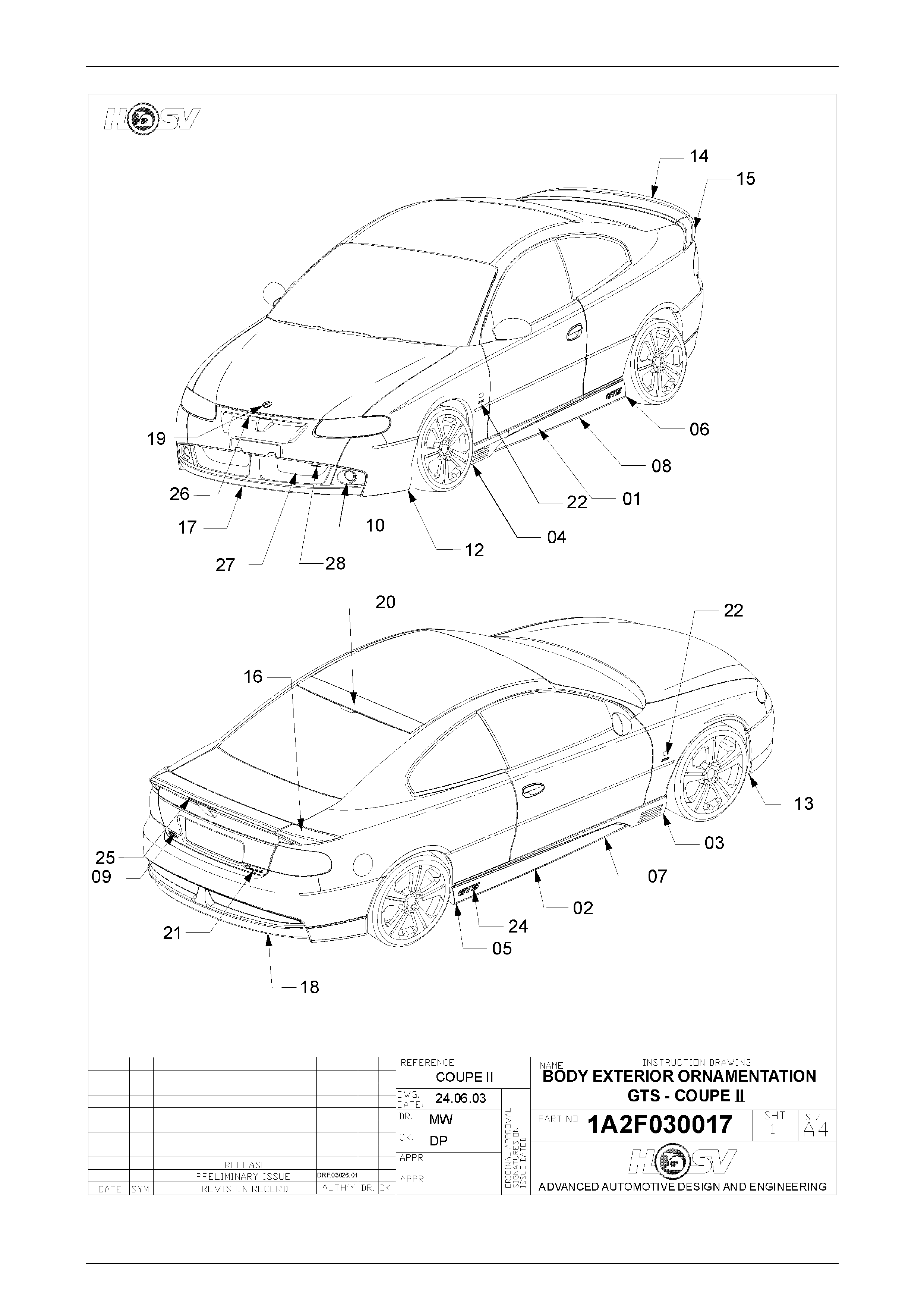
4.2 GTS Coupe Series 2
CONTENTS OF BODY STYLING PACKAGE
REFER TO DRAWING 1A2F030017
PART No QTY DESCRIPTIONS REF
A08-021101 1 SKIRT - ROCKER-LH 1
A08-021102 1 SKIRT - ROCKER-RH 2
A08-021104 1 PAINT PROTECTOR-S/SKIRT FRT RH 3
A08-021103 1 PAINT PROTECTOR-S/SKIRT-FRT LH 4
A08-021106 1 PAINT PROTECTOR-S/SKIRT-RR RH 5
A08-021105 1 PAINT PROTECTOR-S/SKIRT-RR LH 6
A08-021110 1 PAINT PROTECTOR S/SKIRT-SIDE-RH 7
A08-021109 1 PAINT PROTECTOR S/SKIRT-SIDE-LH 8
E08-031108B8 1 BADGE-HSV CORPORATE LOGO 9
B08-970301 1 BADGE-LION & HELMET (BONNET) 19
E08-021101 1 SPOILER - REAR DECKLID – CENTRE – TYPE 1 14
E08-031101 1 SPOILER – REAR DECKLID – CENTRE – TYPE 2 14
E08-021201 1 BADGE – GTS 24
12C-000601 1 LAMP FOG LH 10
12E-031105 1 LAMP ASM-HI MOUNT STOP LIGHT 25
14A-1021101 1 FACIA-FRONT BUMPER BAR 17
14A-2021101 1 FACIA-REAR BUMPER BAR 18
14A-1021110 1 MESH-BUMPER OPENING-UPPER 26
14A-1021111 1 MESH BUMPER OPENING-LWR 27
14A-1021108 1 PAINT PROTECTOR-FRT RH 13
14A-1021109 1 PAINT PROTECTOR-FRT LH 12
E08-970303 1 BADGE – CORPORATE LOGO 22
E08-021102 1 SPOILER – REAR DECKLID – RHS – TYPE 1 16
E08-031102 1 SPOILER – REAR DECKLID – RHS – TYPE 2 16
E08-021103 1 SPOILER – REAR DECKLID – LHS – TYPE 1 15
E08-031103 1 SPOILER – REAR DECKLID – LHS – TYPE 2 15
E08-021104 1 SPOILER - ROOF 20
E08-021105 1 BADGE COUPE 21
E08-020703B8 2 BADGE ENGINE ID 300 22
E08-020706B8 1 GRILLE BADGE GTS 28
Body Page B–14
Page B–14
Body Page B–15
Page B–15
Body Page B–16
Page B–16
Body Page B–17
Page B–17

Body Page B–18
Page B–18
Body Page B–19
Page B–19
Body Page B–20
Page B–20
Body Page B–21
Page B–21
Body Page B–22
Page B–22
Body Page B–23
Page B–23
Body Page B–24
Page B–24
Body Page B–25
Page B–25
Body Page B–26
Page B–26

Body Page B–27
Page B–27
5 Coupe Rear Spoiler – Type 1
ATTENTION
Before performing any Service Operation or other procedure described in this Section, refer to Section 00
CAUTIONS AND NOTES for correct workshop practices with regard to safety and/or property damage.
NOTE
HSV Coupe Models have been fitted with two
designs of spoilers. The difference between the
two spoilers is the attachment method. Early
design spoilers have the RH & LH spoiler sides
retained with mounting studs and urethane
adhesive. Later design spoiler sides are retained
with mounting studs and only use a daub of
urethane adhesive located at the very front
corner.
The type of spoiler fitted can be determined by
first removing the attachings nuts, seals and
washers. If the spoiler is then still firmly attached
to the body panels, it will be the first design of
spoiler (type 1). This has urethane used along its
edges and around the front mounting point. If the
spoiler side is loose and free to move relative to
the body panels, it will be the second design
(type 2) and will only have a small daub of
urethane located at the front edge.
Refer to the removal procedure below.
5.1 Service Operations
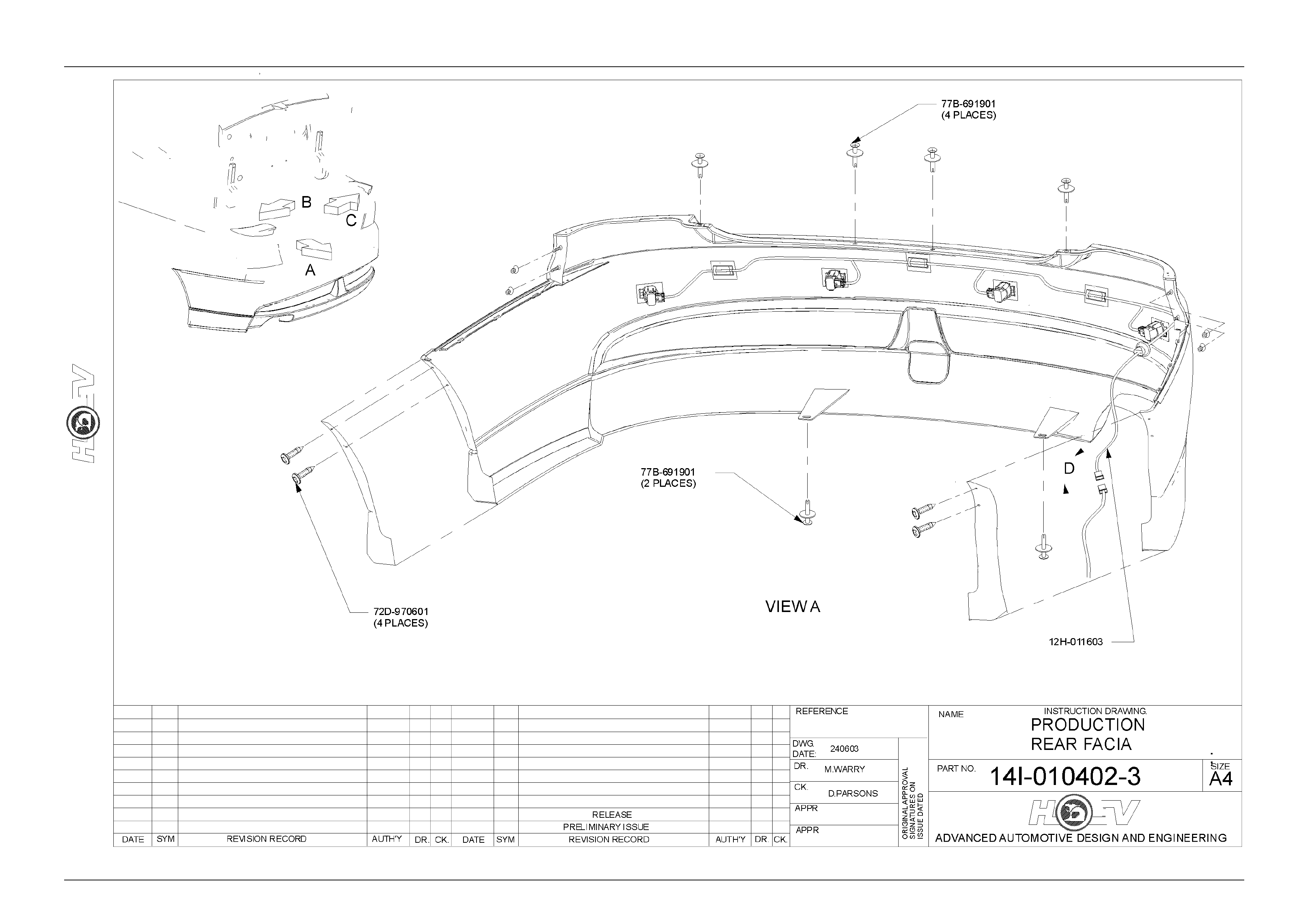
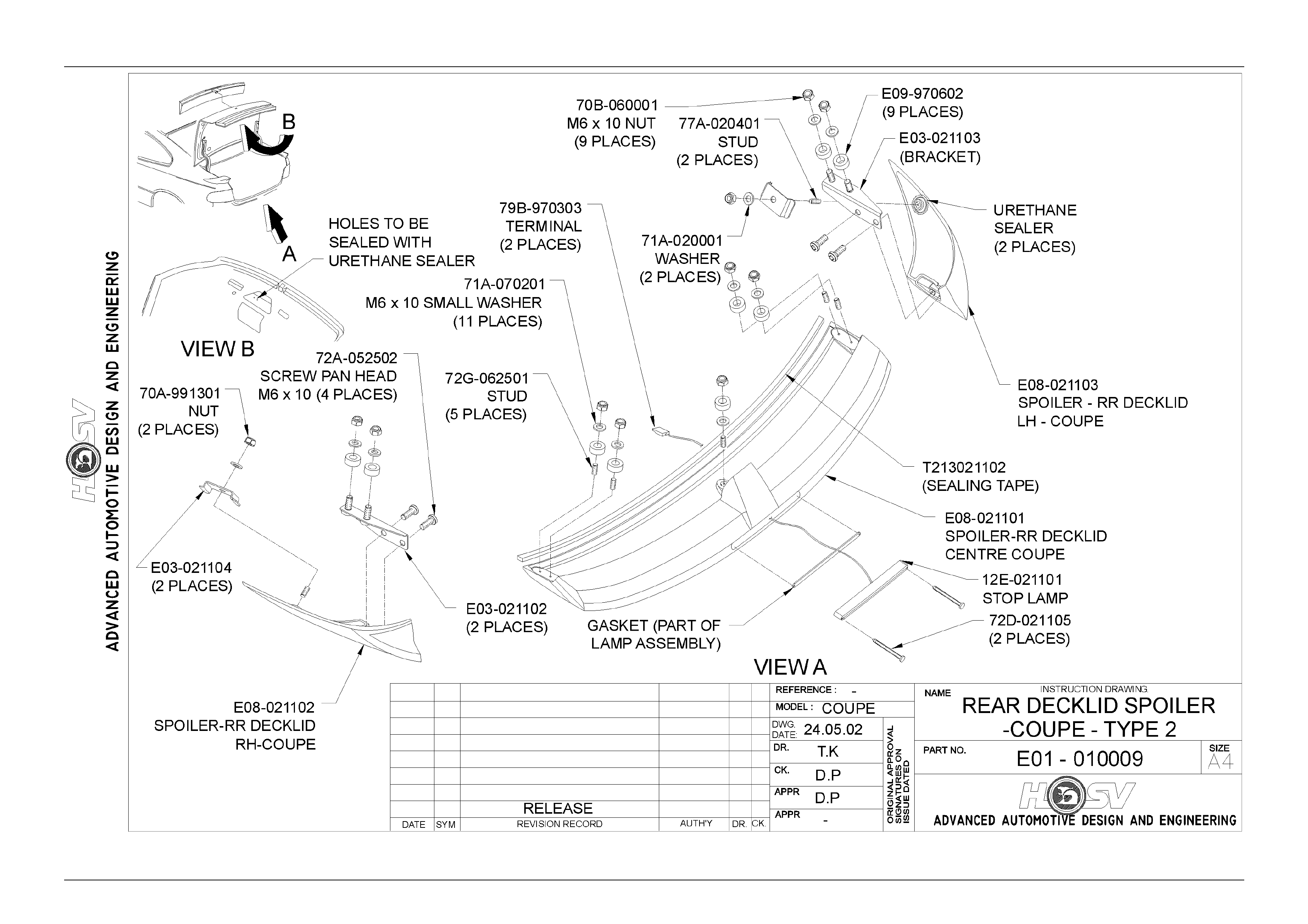
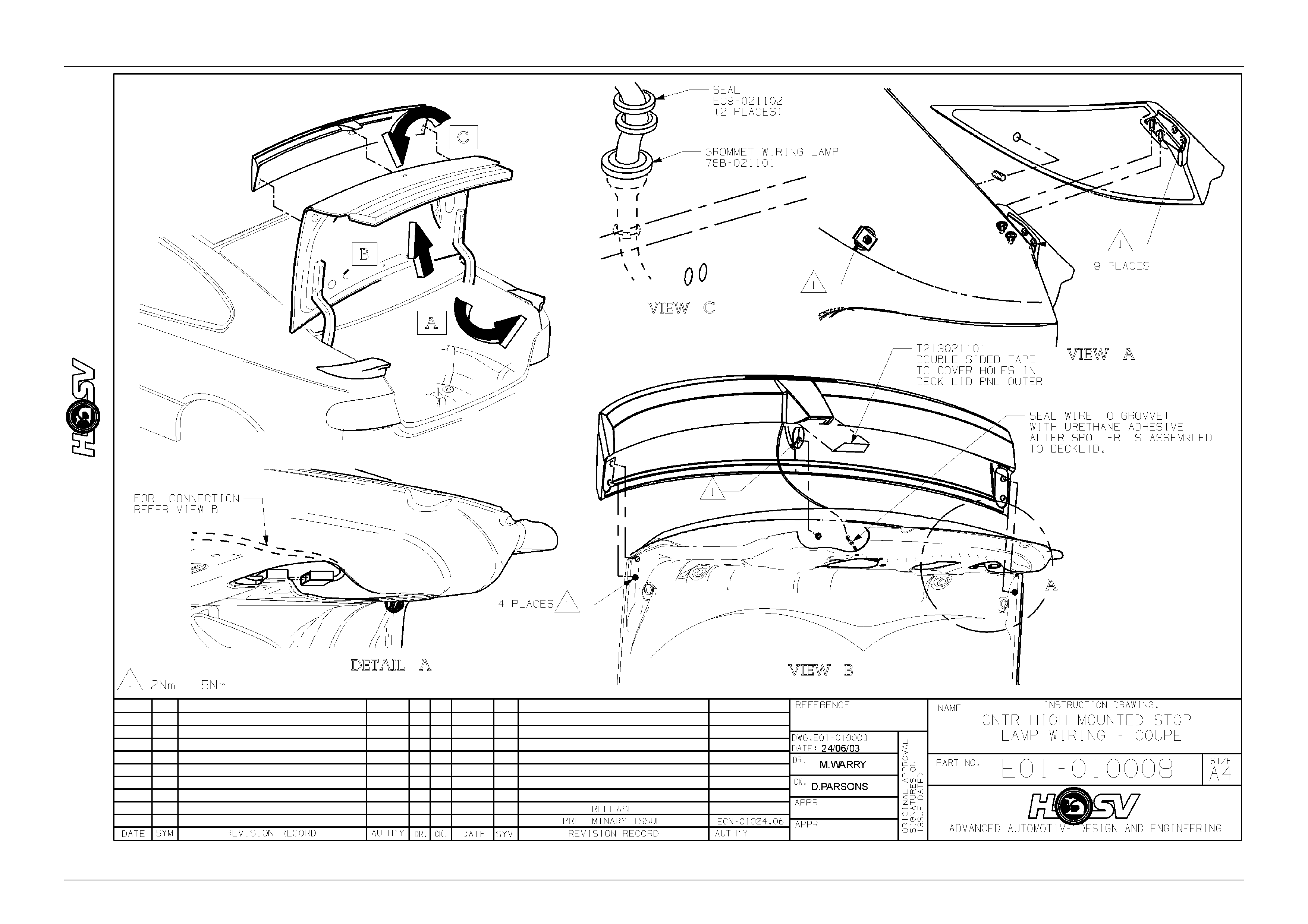
Service Operations for Coupe built Prior to 01.04.03
Refer to Drawing E0I-030007 & E0I-010008
Spoiler Ends Removal
1. Apply masking tape to the Rear Quarter Outer Panel. Tape is to be located hard up against the edges of the spoiler
and to extend a width of at least 100mm around the Spoiler Ends.
2. Open the Trunk Lid.
3. Peal back to side trunk lid Rear Quarter Inner Trim to gain access to the Spoiler Ends front attachments.
4. Remove the attaching nut and bracket.
5. Remove the two Rear Upper Spoiler End attaching bolts and two brackets to spoiler attaching screws and flat
washers.
6. Using a sharp knife cut the Urethane Sealer surrounding the Spoiler Mounting Boss.
7. Slide a Body Filler Applicator or similar stiff plastic plate between the spoiler and body panel to slice through the
Urethane adhesive.
8. Pull the spoiler end away from the Body Panel and carefully cut through any urethane adhesive remaining.
9. Clean the residual Urethane off the body panel with a Profit wheel, decal removing wheel or similar.

Body Page B–28
Page B–28
Spoiler Ends Installation
The installation for the Spoiler Ends is the reverse of the Removal Procedure except that the cutting of the
Urethane Adh es ive is not requir ed.
Spoiler Centre Section Removal
1. Remove the Deck Lid Inner Trim.
2. Refer to the Electrical Section for the removal of the Centre High Mounted Stop Lamp.
3. Remove the Spoiler Centre mounting flanged nut and stud.
4. Remove the four outer attaching nuts and washers (2 per side).
5. Remove the mounting studs from one side of the spoiler.
6. Carefully lift the Spoiler Centre from the Deck Lid.
Spoiler Centre Section Installation
The installation is the reverse of the removal procedure. Do not attempt to install the Centre Spoiler with the studs
installed in the spoile r.
Body Page B–29
Page B–29

Body Page B–30
Page B–30
6 Coupe Rear Spoiler – Type 2
ATTENTION
Before performing any Service Operation or other procedure described in this Section, refer to Section 00
CAUTIONS AND NOTES for correct workshop practices with regard to safety and/or property damage.
NOTE
HSV Coupe Models have been fitted with two
designs of spoilers. The difference between the
two spoilers is the attachment method. Early
design spoilers have the RH & LH spoiler sides
retained with mounting studs and urethane
adhesive. Later design spoiler sides are retained
with mounting studs and only use a daub of
urethane adhesive located at the very front
corner.
The type of spoiler fitted can be determined by
first removing the attachings nuts, seals and
washers. If the spoiler is then still firmly attached
to the body panels, it will be the first design of
spoiler (type 1). This has urethane used along its
edges and around the front mounting point. If the
spoiler side is loose and free to move relative to
the body panels, it will be the second design
(type 2) and will only have a small daub of
urethane located at the front edge.
Refer to the removal procedure below.
6.1 Service Operations
Service Operations for Coupe built after 01.04.03
Refer to Drawing E0I-030008 & E0I-010008
Spoiler Ends Removal
1. Apply masking tape to the Rear Quarter Outer Panel. Tape is to be located hard up against the edges of the spoiler
and to extend a width of at least 100mm around the Spoiler Ends.
2. Open the Trunk Lid.
3. Peal back to side trunk lid Rear Quarter Inner Trim to gain access to the Spoiler Ends attachments.
4. Remove the front attaching nut and bracket.
5. Remove the two Rear Upper Spoiler End attaching bolts and two brackets to spoiler attaching screws and flat
washers.
6. Carefully remove the spoiler and end from the body work.
Spoiler Ends Installation
The installation for the Spoiler Ends is the reverse of the Removal Procedure.

Body Page B–31
Page B–31
Spoiler Centre Section Removal
1. Remove the Deck Lid Inner Trim.
2. Refer to the Electrical Section for the removal of the Centre High Mounted Stop Lamp.
3. Remove the Spoiler Centre mounting flanged nut and stud.
4. Remove the four outer attaching nuts and washers (2 per side).
5. Remove the mounting studs from one side of the spoiler.
6. Carefully lift the Spoiler Centre from the Deck Lid.
Spoiler Centre Section Installation
The installation is the reverse of the removal procedure. Do not attempt to install the Centre Spoiler with the studs
installed in the spoile r.

Body Page B–32
Page B–32
7 Servicing the HSV Coupe Rear
Spoiler
These instructions explain how to achieve the correct attaching hole locations for the rear spoilers.
Two service procedures are explained, first a vehicle with undamaged body panels and also where body panel
replacement is involved.
7.1 Servicing Coupe Rear Spoilers –
Undamaged body panels
When servicing HSV Coupe Rear Spoilers the following procedure is used if body panel replacement is not
involved. The existing attaching holes may require slotting to suit the new spoiler.
Centre Spoiler
• Slotting may be required on the centre spoiler attaching holes.
• Slotting if required would be about 2 mm - 3 mm.
• The direction and amount can be determined by taping the spoiler in position onto the body panels
with masking tape then with the aid of a lamp sighting the attaching holes from underneath with the
Deck Lid open and the Rear Compartment Trim removed if required.
• The holes may possibly be up to half a hole out. Slot the holes to suit the spoiler attachments.
Outer Spoilers
• Slotting of the upper mounting holes may or may not be necessary.
• This must be evaluated with the Centre Spoiler fitted and the deck lid closed.
• Assemble the Side Spoiler into position on the Rear Quarter Outer Panel with masking tape to retain
it. Open the Deck Lid to gain access to the Rear Compartment.
• With the aid of a lamp sight the Side Spoiler upper mounting holes to check the alignment of the
spoiler attachments.
• The misalignment (if any) of the holes is the amount of slotting necessary for the upper mounting
holes. Slot the holes to suit.
Att achi ng Part s
• The later type Spoiler Sides use the front corner attaching nut (M5) part number 70A-991301
quantity one per side (this is an M5 flange nut and earlier spoilers had M6 nuts).
Sealing
• Once all spoiler components are in place ensure the seals cover the mounting holes.
General Precaution
• After all holes have been drilled or slotted perform a trial fitment check with all parts using masking
tape to hold seals in place, do not remove adhesive protection film from the seals until final assembly
is undertaken.
• Cover all components inside the rear compartment to protect against ingress of drilling swarf and
dust.
• De-burr all holes prior to painting.
• If parts of the spoiler assembly are still serviceable, not damaged and still located correctly on the
vehicle they can be used to assist with alignment of the replacement parts.
• All parts of the spoiler (center and sides) are to be temporarily attached to the vehicle in position with
masking tape while preliminary fitment check is completed.
• Check the gaps and alignment of the 3 spoiler components at all assembly stages of this procedure.
Body Page B–33
Page B–33
7.2 Servicing HSV Coupe Rear Spoilers –
Where Service Replacement Body
Panels are Installed
If panel replacement is involved in the vehicle repair, holes will need to be drilled to suit the spoilers.
All holes drilled and punched are to be completed after the panels have been fitted to the vehicle but prior to
priming and painting.
If part of the spoiler is still serviceable is not damaged, still located correctly on the vehicle and will be reused, it
can be used to assist with alignment of the replacement parts.
To locate Attaching Holes
• All parts of the spoiler (center and sides) are to be temporarily attached to the vehicle in position with
masking tape.
• Check the gaps and alignment of the 3 spoiler components.
Alignment Tape
• With the spoilers located and taking care to avoid the spoiler retaining tape previously applied,
accurately apply 12 mm wide masking tape on the body panels aligned with the outer edges of the 3
spoilers. NOTE, The edge of the masking tape will give reference edges for the spoiler profiles to
work with for locating attaching holes.
• Carefully remove the spoilers from the body taking care not to damage the alignment tape shows the
reference edges.
Locating Attaching Holes
• Carefully lay the spoilers upside down on a table covered with protective cloth (to avoid surface
damage) and measure the attachment locations from the outer edges of the spoilers.
Marking Locating Holes on Body Panels
• Transfer the attachment positions back to the body panels using the edge tape as a reference.
• Masking tape and a suitable marker can be used to show the hole centres. Paper templates can be
made by the same method if it is deemed to be of assistance.
Drilling Attaching Holes
• Carefully drill 6,0 mm pilot holes in the positions marked.
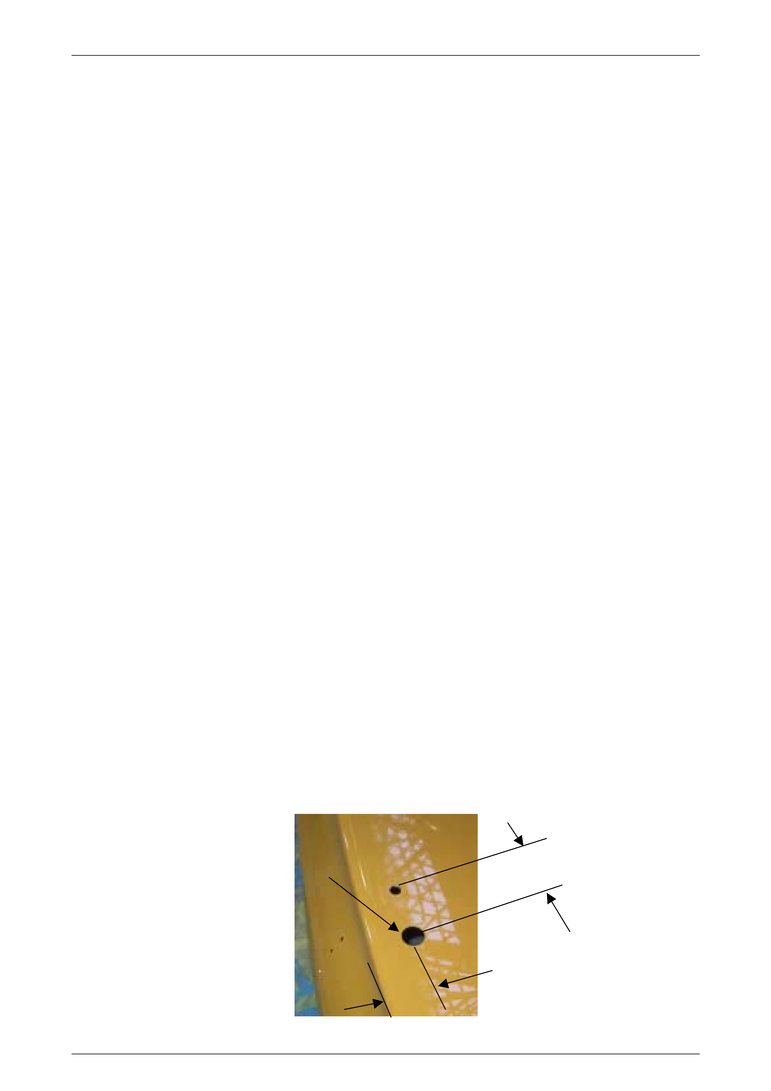
Drilling Wiring Hole
• The spoiler wiring hole (CHMSL) is located 50 mm to the RH side of the centre mounting hole and
38 mm forward of the vertical edge of the deck lid.
• A hole is drilled to suit a 19 mm chassis punch. Refer to image below.
50 mm
38mm
19 mm Diam
Hole

Body Page B–34
Page B–34
Spoiler Re-Assembly
• Using masking tape to retain the parts, re-assemble the spoilers to the body aligning the edges of
the spoiler with the edge reference tape.
Attaching Hole Location Check
• Carefully open the deck lid (take care not to dislodge the centre spoiler).
• With the aid of a light, sight the pilot holes to check the alignment of the spoiler attachments with the
drilled holes.
Attaching Hole Size
• If the centre spoiler holes align correctly remove the spoiler and open the hole size up to 9,0 mm
using a step drill. If the holes do not align slot as required but do not exceed the seal coverage area
(refer to attaching parts).
Spoiler Sides
• The spoiler sighting procedure will require repeating on the spoiler sides but the 26 mm front
attaching hole needs to be punched first.
Side Spoiler Front Attaching Hole
• The front mounting hole of the side spoiler will need the pilot hole drilled out to suit the bolt on a 26,0
mm chassis punch.
• Punch the hole to 26,0 mm.
Upper Attaching Hole
• If the upper holes align correctly open the pilot holes up to 9,0 mm using a step drill. If the holes do
not align slot as required but do not exceed the seal coverage area (refer to attaching parts).
General Precaution
• After all holes have been drilled and punched perform a trial fitment check with all parts using
masking tape to hold seals in place, do not remove adhesive protection film from the seals until final
assem bl y is undertak en.
• Cover all components inside the rear compartment to protect against ingress of drilling swarf and
dust.
• De-burr all holes prior to painting.
• If parts of the spoiler are still serviceable, not damaged and still located correctly on the vehicle they
can be used to assist with alignment of the replacement parts.
• Check the gaps and alignment of the 3 spoiler components at all assembly stages of this procedure.
Body Page B–35
Page B–35
Body Page B–36
Page B–36
Body Page B–37
Page B–37
Body Page B–38
Page B–38

Body Page B–39
Page B–39
8 Roof Spoiler
ATTENTION
Before performing any Service Operation or other procedure described in this Section, refer to Section 00
CAUTIONS AND NOTES for correct workshop practices with regard to safety and/or property damage.
8.1 Service Operations
Roof Spoiler Removal
NOTE
The roof spoiler is adhered to both the rear
window glass and the rear of the rear outer panel
with Urethane adhesive. Care must be taken not
to damage the paintwork of the vehicle when
performing this operation.
1. Apply masking tape up against the front and side edges of the roof spoiler. The tape must extend for a distance of
atleast 75mm away from the edges of the spoiler. This tape is to protect the roof and rear quarter panels from
damage when removing the spoiler and adhesive.
2. Slide a body filler applicator or similar stiff plastic plate between the spoiler and the body panels. Using a cutting
action like a knife, break the Urethane adhesive bond. The cutting will need to be done across the roof panel, down
the sides of the glass and also across the glass in the centre of the spoiler. The spoiler maybe pulled away from the
panels for access to the Urethane, but extreme care must be taken to avoid damage to the panels and paint work.
3. Clean the excess Urethane off the glass and panel work with a profit wheel, decal removing wheel or similar.
Extreme care must be taken to avoid damage to the panels and paint work.
Roof Spoiler Installation
1. Remove the protective masking tape used in the removal procedure.
2. Clean the attaching area with Urethane cleaner and prime the contact area.
3. With the assistance of another person locate the spoiler centrally between the roof mouldings (at the
sides of the rear glass) and align the spoiler side notches (located towards the top edge of the spoiler)
with the top rear window gl as s mouldi ng.
4. Using a china graph pencil (white) or similar place alignment marks on the spoiler and the body. These
will be used for location of the spoiler on the vehicle when the adhesive is applied.
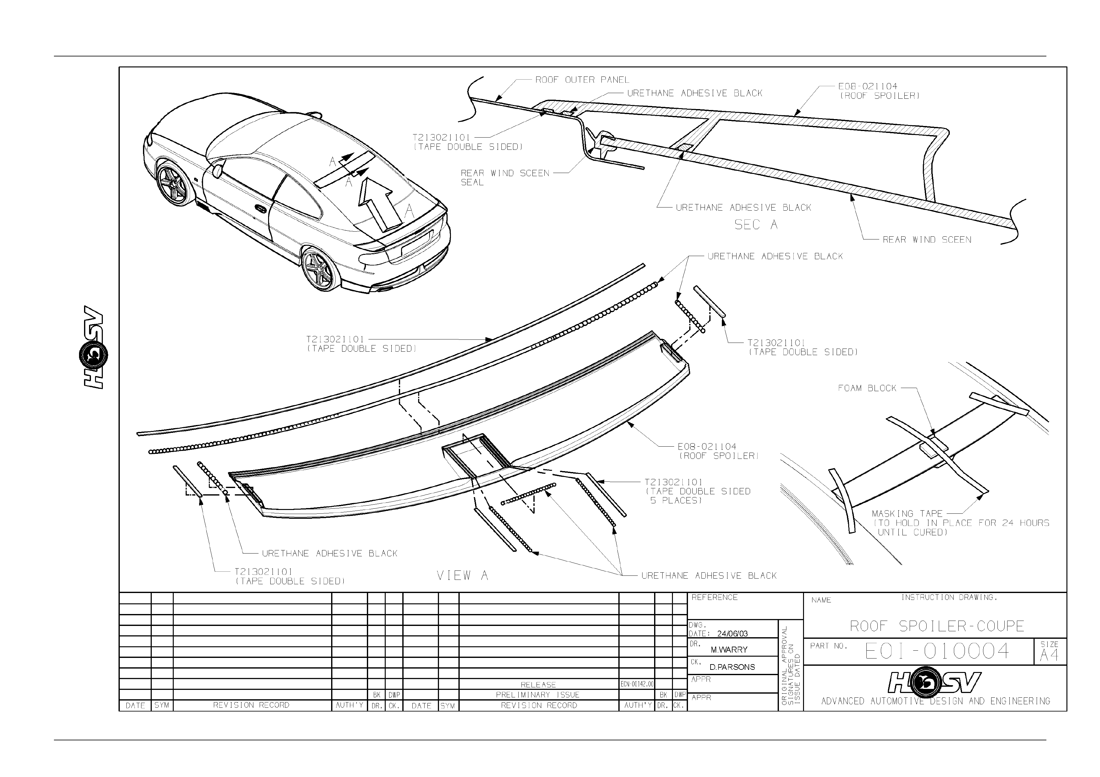
5. Place the new spoiler upside down on a protective cloth and apply Urethane adhesive along the front
edge, sides and central leg as shown on drawing E0I-010004.
6. Locate the spoiler in position on the vehicle using the previously applied location marks (china graph
pencil).
7. Take the spoiler to hold it in position while the Urethane adhesive cures refer drawing E0I-010004.
The cure time for the Urethane adhesive is 24 hours, it is not recommended that the tape be
removed or the vehicle be driven in this period.
8. Remove the tape from the spoiler and the vehicle after the 24-hour cure time and polish the area to
remove any foreign matter, which may have been left by this procedure.
Body Page B–40
Page B–40