
Options Page J–1
Page J–1
Section J
Options
ATTENTION
Before performing any Service Operation or other procedure described in this Section, refer to Section 00
CAUTIONS AND NOTES for correct workshop practices with regard to safety and/or property damage.
1 Purpose................................................................................................................................................... 2
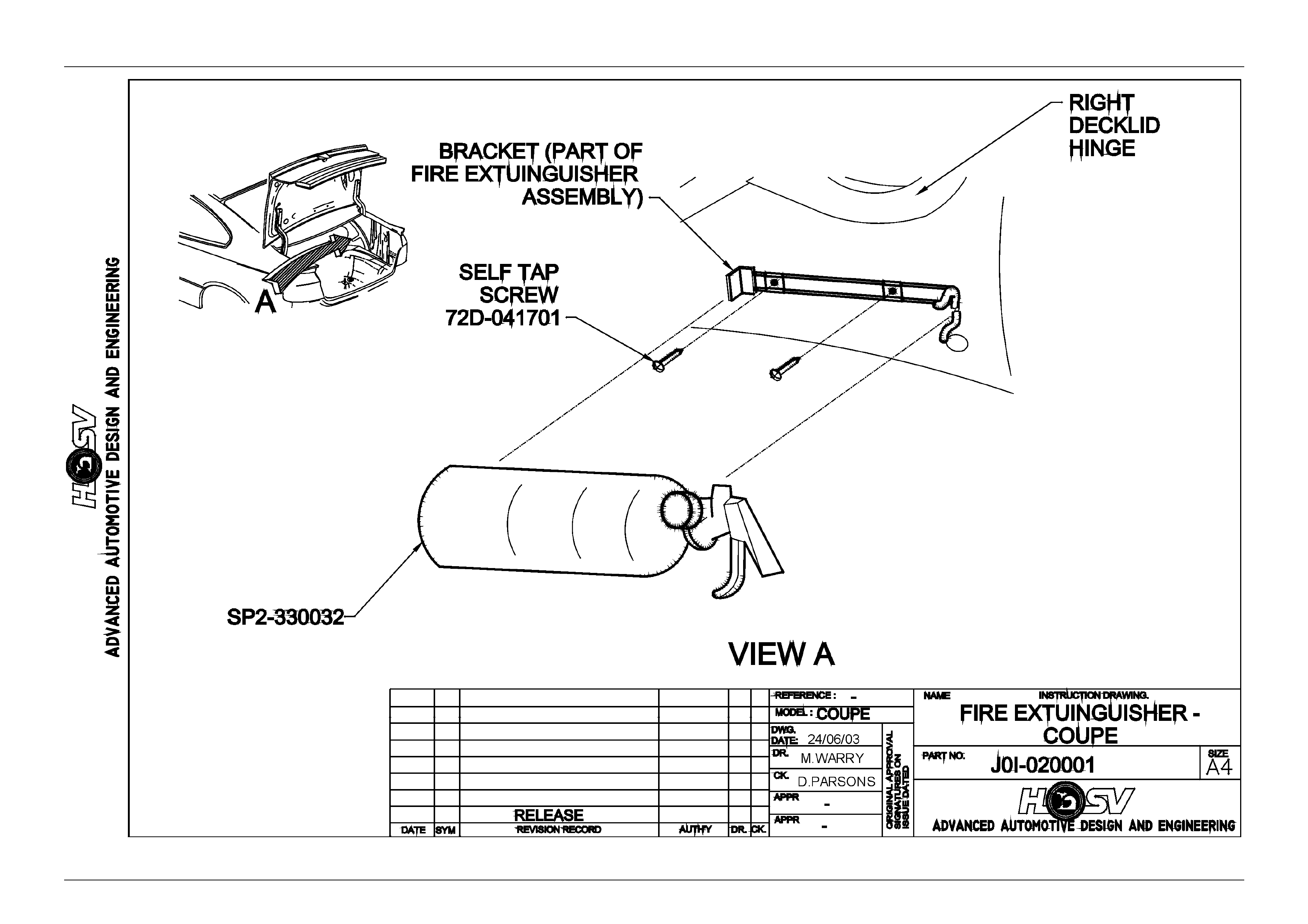
2 Fire Extinguisher ................................................................................................................................... 3
2.1 General Information...............................................................................................................................................3
2.2 Service Operations.................................................................................................................................................4
3 HSV Embedded Security System GTO And GTS Coupe Series 2 ....................................................6
3.1 General Information...............................................................................................................................................6
3.2 Linking The ESS To A New BCM At The Car Dealer – BCM In Warranty...........................................................7
3.3 Linking The ESS To A New BCM At The Car Dealer – BCM Out Of Warranty...................................................8
3.4 Key Programming Mode........................................................................................................................................9
Programming Extra Keys to the Vehicle..............................................................................................................9
Programming All New Key.....................................................................................................................................9
3.5 Link Enable Procedure ........................................................................................................................................10
3.6 Service Operations...............................................................................................................................................11
4 HSV Fog Lamps ................................................................................................................................... 16
4.1 General..................................................................................................................................................................16
4.2 Service Operation.................................................................................................................................................17

Options Page J–2
Page J–2
1 Purpose
The purpose of this supplement is to provide information on the special options and accessories fitted to the HSV GTO
and GTS Coupe Series 2 models. This information is designed to supplement that contained in the Holden V2 Coupe
series Service Manuals, and details are given where differences occur between the HSV models and standard Holden
models. A series of instruction drawings detail the design changes and indicate specific part numbers, fitting instructions
and relevant notes for vehicle servicing.
NOTE
If specific technical data on a HSV model is not
contained in this supplement, obtain data for that
model from the relevant Holden V2 Coupe Series
2 Service Information. References are made
throughout this section to Holden Service
Manuals, to assist in providing information for
specific serv ice operati ons .
CAUTION
When hoisting (or jacking) HSV models,
ensure that the lifting head of the hoist lifts on
the chassis before the arm of the hoist
contacts the side-skirt


Options Page J–4
Page J–4
2.2 Service Operations
The fire extinguisher should be subjected to a regular visual inspection in accordance with the instructions on the
extinguisher. Particularly, the extinguisher should be inspec ted for damage and to ensure that the integral pressure
gauge registers the appropriate internal pressure. When discharged or when the internal pressure is outside the
prescribed limits, the extinguishers should be serviced and re-charged by an appropriate supplier. New extinguishers
are available through the HSV spare parts system.
Options Page J–5
Page J–5

Options Page J–6
Page J–6
3 HSV Embedded Securit y System
GTO And GTS Coupe Series 2
3.1 General Information
The new HSV Embedded Security System (ESS) is fitted as standard equipment to all HSV GTO and GTS Coupe Series
2 models. The ESS is a micro-processor controlled immobiliser, which automatically interrupts essential electrical circuits
when in “armed mode”. The ESS stores the BCM’s security code and when the car is started it reads this code from the
SCI bus. If this code is different from the stored one the ESS enters armed mode and prevents the vehicle from starting.

Options Page J–7
Page J–7
3.2 Linking The ESS To A New BCM At The
Car Dealer – BCM In Warranty
If the BCM requires replacement within the BCM warranty period, the Dealer shall be supplied with a replacement BCM
programmed wi th the same BCM security code as the orig inal BCM. In this case, the replacement BCM and new keys
are simply fitted to the vehicle. No ESS specific requirements are needed.

Options Page J–8
Page J–8
3.3 Linking The ESS To A New BCM At The
Car Dealer – BCM Out Of Warranty
When a BCM requires replacement outside the BCM warranty period the Dealer shall need to obtain a
replacement BCM and keys from Holden’s Service Parts Operation (HSPO). The replacement BCM and
Keys will not contain the same BCM Security Code as the original BCM.
When a new BCM with different BCM security code is fitted to the vehicle, the dealer will have to do the following:
- Program a new key to the BCM.
- Link the BCM and PCM.
TECH 2 must be connected to the vehicle diagnostic connector whilst the key is being programmed and/or ESS is being
linked to the vehicle. The Link Enable Procedure is required to be performed twice to allow an all new key to be
programmed and also allow the ESS learn to learn the BCM security code. The procedure for programming a new k ey to
a new BCM and linking the ESS to the vehicle is as follows:
1. Fit new BCM to the vehicle.
2. Ensure all doors, boot and bonnet are closed, all doors are unlocked, dome lamp is in the ‘doors’ position and the
radio, headlight and wash-wipe switches are off.
3. Place new key into the ignition barrel.
4. Turn ignition on. Verify ESS beeps 5 times.
5. TECH2 must be operating in the “Data Display \ Inputs & Outputs” submenu of the Body Control Module sub-
menu.
6. Perform the Link Enable Proced ure (see Section 3.5). Wait 1 second between each lock unlock to ensure the door
lock actuators function correctly during this procedure.
7. Verify that the ESS beeps twice. TECH2 reports ignition is at 12Vdc. The ESS has now entered “Key Programming
mode”.
8. Select Key Programming function – “All New Key” - from the security sub-menu in the body menu of the TECH2.
Enter BCM security code as requested by TECH2. Complete key programming as requested by TECH2.
9. Turn ignition off and wait for 2 seconds. Turn ig nition on.
10. Verify ESS beeps 5 times. (At this stage the ESS is in “armed mode”).
11. TECH2 must be operating in the “Data Display \ Inputs & Outputs” submenu of th e Body Control Module sub-
menu.
12. Perform the Link Enable Procedure (s ee Section 3.5). Wait 1 second betw een each lo ck unl ock to ensure the door
lock actuators function correctly during this procedure.
13. Verify that the ESS beeps twice. TECH2 reports ignition is at 12Vdc.
14. Link the PCM to the BCM using TECH2. ESS beeps twice (ESS has now learned the BCM security code).
15. Turn ignition off. Wait until TECH2 programming is co mpl ete .
16. Turn ignition on.
17. Turn ignition off. Wait 2 seconds.
18. Turn ignition on.
19. Verify ESS beeps once. The ESS is now operating in “normal mode”.
20. Crank engine. Verify vehicle starts as normal.

Options Page J–9
Page J–9
3.4 Key Programming Mode
Once the ESS has been placed into key programming mode the ESS will behave as if in “sleep mode” for one ignition
cycle only. This allows for the one ignition cycle that is required to program a new key to a new or existing BCM. The
ESS will enter “normal mode” for the next ignition cycle. If the BCM is a new BCM in the vehicle with a new security
code, the ESS will then enter “armed mode” as expected.
Pr ogr amming E xtra Keys to the Vehicle
Programming more k e ys for the vehicle can be achieved using TECH2 once the ESS has been re-linked to the vehicle
as described as follows :
1. Ensure all doors, boot and bonnet are closed, all doors are unlocked, dome lamp is in the ‘doors’ position and the
radio, headlight and wash-wipe switches are off.
2. Place new key into the ignition barrel.
3. Turn ignition on. Verify ESS beeps 5 times.
4. TECH2 must be operating in the “Data Display \ Inputs & Outputs” submenu of the Body Control Module sub-
menu.
5. Perform the Link Enable Procedure (see Section 3.5). W ait 1 second between each lock unlock to ensure the door
lock actuators function correctly during this procedure.
6. Verify that the ESS beeps twice. TECH2 reports ignition is at 12Vdc. The ESS has now entered “Key Programming
mode”.
7. Select Key Programming function – “Extra Key” – from the security sub-menu in the body menu of the TECH2.
When TECH2 requests ignition to be cycled with the existing key, leave the new key in the ignition barrel and
instead, press the unlock button on the existing key. Verify th e ESS beeps once and the Theft Deterrent LED stops
flashing. Complete key programming as requested by TECH2.
8. Turn ignition off and wait for 2 seconds.
9. Turn ignition on. Verify ESS beeps once. The ESS is now operating in “normal mode”.
10. Crank engine. Verify vehicle starts as normal.
Programming All New Key
Programming an All New Key for the vehicle can be achieved by performing the following procedure:
Ensure all doors, boot and bonnet are closed, all doors are unlocked, dome lamp is in the ‘doors’ position and the radio,
headlight and wash-wipe switches are off.
1. Place new key into the ignition barrel.
2. Turn ignition on. Verify ESS beeps 5 times.
3. TECH2 must be operating in the “Data Display \ Inputs & Outputs” submenu of the Body Control Module sub-
menu.
4. Perform the Link Enable Procedure (see Section 3.5). W ait 1 second between each lock unlock to ensure the door
lock actuators function correctly during this procedure.
5. Verify that the ESS beeps twice. TECH2 reports ignition is at 12Vdc. The ESS has now entered “Key Programming
mode”.
6. Select Key Programming function – “All New Key” - from the security sub-menu in the body menu of the TECH2.
Enter BCM security code as requested by TECH2. Complete key programming as requested by TECH2.
7. Turn ignition off and wait for 2 seconds.
8. Turn ignition on. Verify ESS beeps once and Theft Deterrent LED is off. The ESS is now operating in “Data Display
\ Inputs & Outputs”.
9. Crank engine. Verify vehicle starts as normal.

Options Page J–10
Page J–10
3.5 Link Enable Procedure
Each ESS has it’s own unique Link Enable Code (LEC), programmed into each ESS by HSV. This code corresponds to a
unique sequence of 10 vehicle body func tions comprising of the following actions:
1. Drivers door. Open then Close
2. Drivers door. Lock then Unlock
3. Wash-Wipe. On then off.
Approximately 60,000 link enable codes are available.
For the Link Enable Procedure contact
Australian Arrow Pty Ltd Customer Service
Quoting ESS PIN and Vehicle Identification / Tag Number.
Telephone: (03) 9785 0792
Facsimile: (03) 9775 0954

Options Page J–11
Page J–11
3.6 Service Operations
In the event of a suspected ESS failure the following diagnostic procedure must be followed:

HSV – EMBEDDED SECURITY SYSTEM (ESS) CHECK SHEET (VT.II / WH / VY / WK / VZ).
In the event of a suspected ESS failure, fill in the following check sheet.
STEP ACTION MEASURED VALUE
YES NO
• What type of vehicle has the suspected ESS failure? VT.II : VY :
WH : WK:
VZ :
1 • Turn ignition to ON position and listen for the number of beeps. Zero beeps:
One beep:
Five beeps: Other:______
2 • With the ignition in the ON position, is the Theft Deterrent Led flashing?
3 • Turn Ignition switch to the Start position.
• Does the vehicle start?
4 • Has there been a BCM replacement?
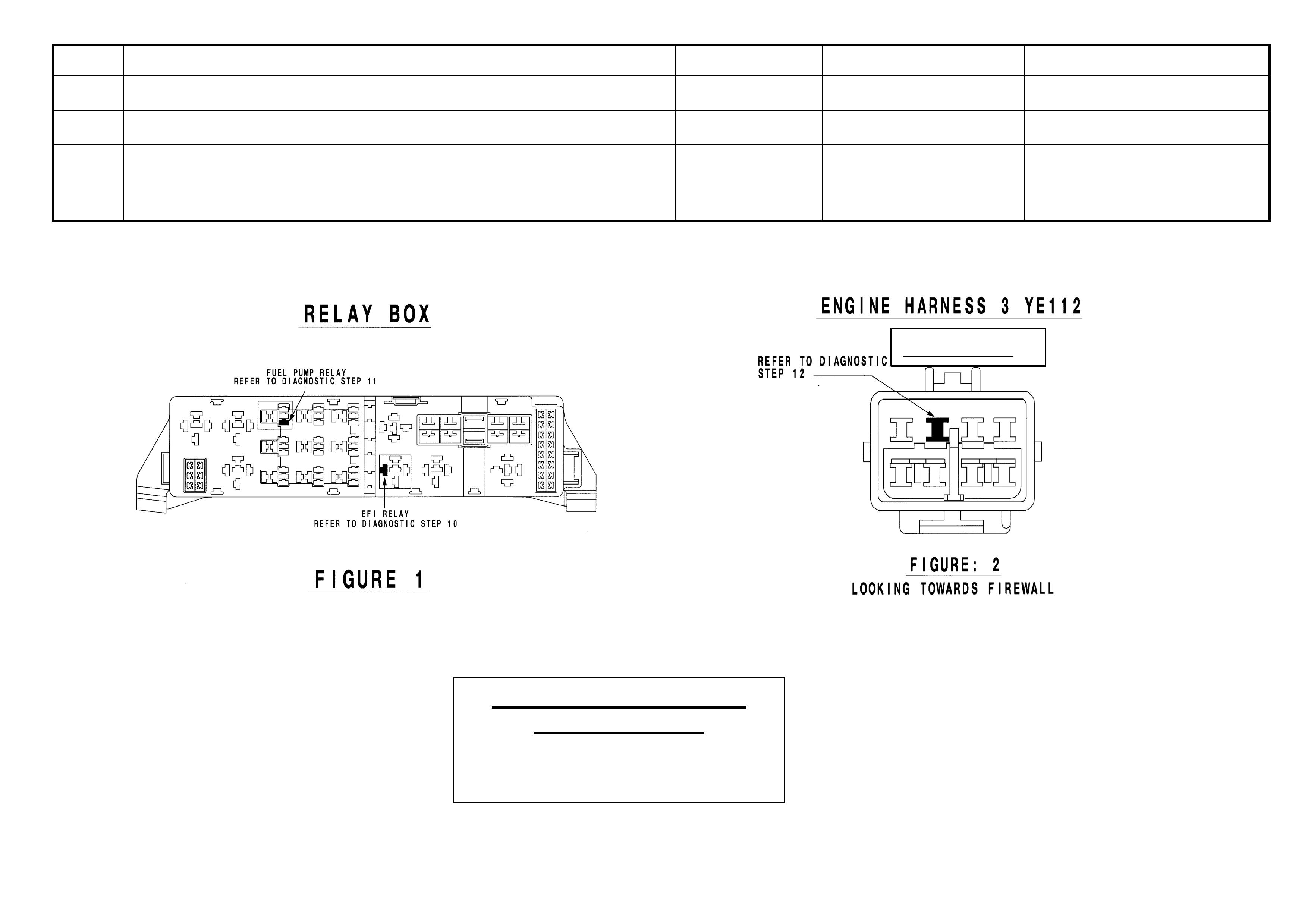
5 • Remove the EFI relay and back probe terminal 85 (as per figure 1 for VT.II / WH Vehicles or as per figure 3 for
VY / WK/ VZ Vehicles), with reference to Ground.
• With the Ignition switch to ON, measure DC voltage.
_____________ volts DC.
6 • Remove Fuel Pump relay and back probe terminal 1 (as per figure 1 for VT.II / WH Vehicles) or terminal.2 (as
per figure 3 for VY / WK Vehicles) , to measure continuity with ref. to Ground.
• Turn the ignition to ON, measure resistance.
_____________ Ohms.
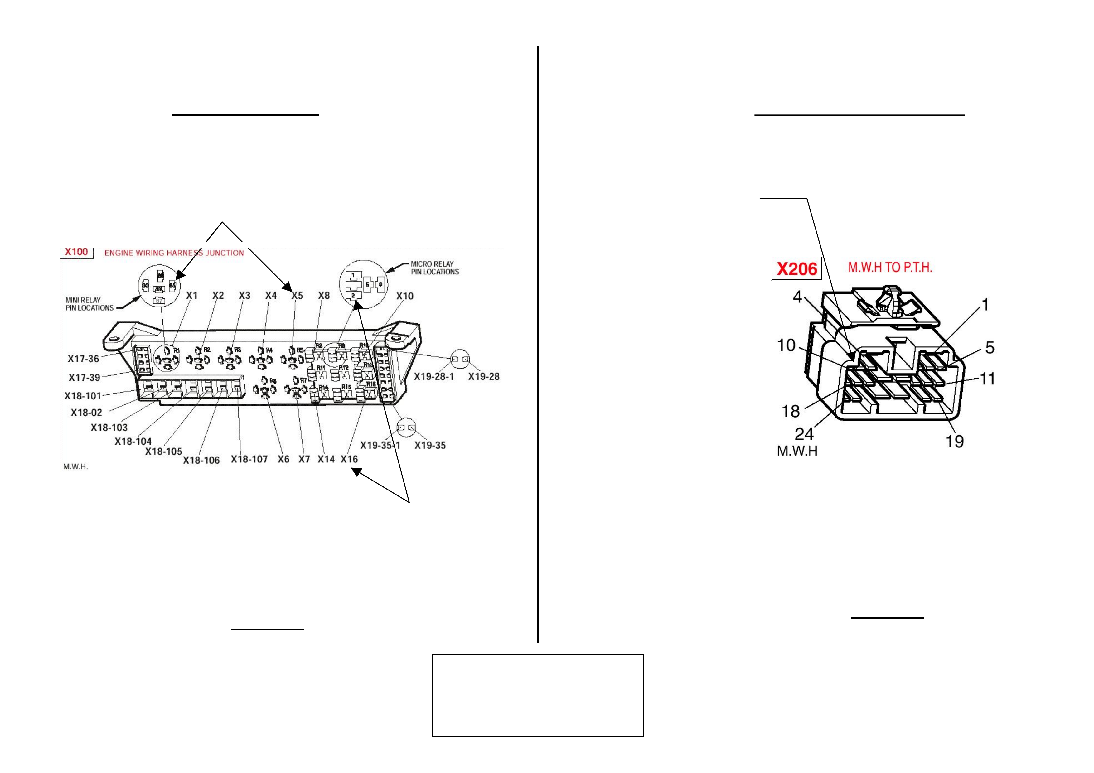
7 • For VY / WK Vehicles Disconnect Engine Connector (X206 located above passe nge r k i ck pa nel ) and back pr obe
pin 9 (as per figure 4) with reference to ground.
• For VT.II / WH Vehicles Di s c on nect En gi n e Connector (YE112) and back probe pin (as pe r fi g ure 2 ), wit h
reference to Ground.
• For VZ vehicles Disconnect ECM connector A43 X1 and back probe pin 19 (as per figure 5) with reference to
ground.
• Turn the ignition to ON, measure DC voltage.
_____________ volts DC
8 • Is communications with Tech 2 active?
9 • With TDL flashing, operate “Unlock” button on the Remote Control.
• Does the TDL stop flashing?
Dealer Code: ISOVIN: Vehicle Build Date:
Km’s: ESS Pin No: BCM Part No: BCM Barcode No: .
This check sheet must signed by the Service Manager. ____________________________ Date: ____________
Fax the completed copy to Australian Arrow Customer Service. Facsimile: (03) 9775 0954.

HSV – EMBEDDED SECURITY SYSTEM (ESS) DIAGNOSTIC PROCEDURE (VT.II / WH / VY / WK / VZ).
STEP ACTION VALUE YES NO
1 • Turn ignition to ON position.
• Is one (1) beep audible?
• Go to Step 2 • Go to Step 3.
2 • Turn Ignition switch to the Start position.
• Does the vehicle start?
• System O.K, return
vehicle to customer.
• Go to Step 11.
3 • Are five (5) beeps audible? • Go to Step 13. • Go to Step 8.
4 • Turn Ignition switch to the Start position.
• Does the vehicle start?
• Go to Step 5. • Go to Step 6.
5 • Fill in the ESS check sheet and Contact Australian Arrow
Customer Service.
6 • Has there been a BCM replacement? • Go to Step 5. • Go to Step 14.
7 • Perform Serial Data Communications diagnostic as per Holden
Service Manual, then go to Step 5.
8 • Zero beeps were audible? • Go to Step 9. • Record number of beeps,
then go to Step 5.
9 • Turn Ignition switch to the Start position.
• Does the vehicle start?
• Go to Step 5. • Go to Step 10.
10 • Remove the EFI relay and back probe terminal 85 (as per figure.1
for VT.II / WH vehicle), or (as per figure.3 for VY/WK/VZ
vehicle), with reference to Ground.
• With the Ignition switch to ON, Is the value as specified?
• 12 volts DC. • Go to Step 5. • Refer to Service Manual
and check Ignition
system.
11 • Remove Fuel Pump relay and back probe terminal.1 (as per figure.1
for VT.II / WH vehicle), or (as per figure.3 terminal.2 for
VY/WK/VZ vehicle), to check continuity with reference to Ground.
• Turn the ignition to ON. Is the value as specified?
• Less than one
(1) Ohm.
• Go to Step 12. • Go to Step 5.
12 • For VT.II / WH vehicle, Disconnect Engine Connector (YE112)
and back probe pin (as per figure 2), with reference to Ground.
• For VY/WK vehicle, Disconnect Engine Connector (X206 located
above passenger kick panel), and back probe pin.9 (as per figure.4),
with reference to ground.
• For VZ vehicles Disconnect ECM connector A43 X1 and back
probe terminal 19 (as per figure 5) with reference to ground.
• Turn the ignition to ON. Is the value as specified?
• 12 volts DC • Go to Step 5. • Go to Step 5.
STEP ACTION VALUE YES NO
13 • Is the Theft Deterrent Led flashing? • Go to Step 4. • Go to Step 5.
14 • Is communications with Tech 2 active? • Go to Step 15. • Go to Step 7.
15 • With TDL flashing, operate “Unlock” button on the Remote Key.
• Does the TDL stop flashing?
• Go to Step 5. • Refer to Theft Deterrent
System diagnostics in
Holden Service Manual.
(Grey Connector)
Australian Arrow Pty. Ltd.
Customer Service.
Telephone: (03) 9785 0792
Facsimile: (03) 9775 0954
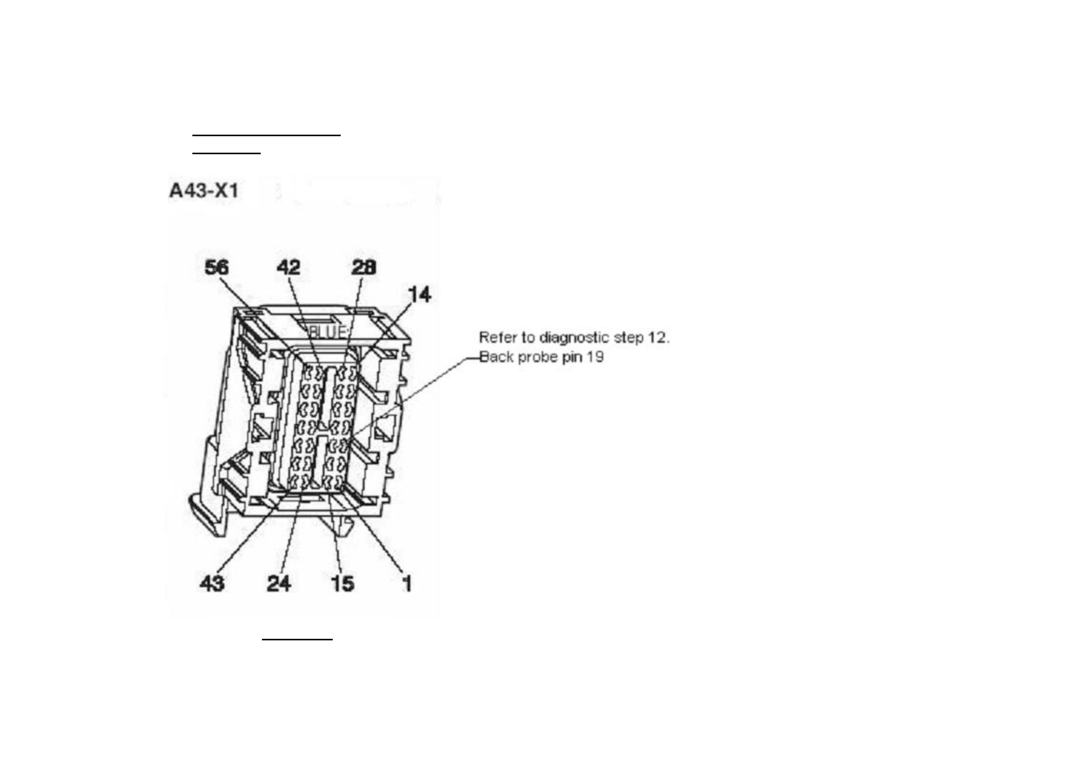
Engine control module
connector.
FIGURE 5
Fuel pump relay (X16)
Refer to diagnostic STEP 11
Back probe terminal 2
EFI relay (X5)
Refer to diagnostic Step 10
Back probe terminal 85
Refer to diagnostic step 12 (Pin 9)
FIGURE 3
Engine harness connector X206 Engine bay Relay Box
FIGURE 4
Australian Arrow Pty Ltd.
Customer Service
Telephone: (03) 9785 0792
Facsimile:(03)9775 0954

Options Page J–16
Page J–16
4 HSV Fog Lamps
4.1 General
HSV Fog lamps are fitted directly to the front fascia of all HSV Coupe Series 2 models. The HSV lamps use a glass
convex reflector to provide a wide-angle beam concentrated in a range of 30 to 40 metres in front of the lamp. The
external lens incorporates a clear horizontal section.

Options Page J–17
Page J–17
4.2 Service Operation
No periodic servicing of the HSV lamps is required. Globes may be replaced by removing a water-tight access cover on
the rear of the lamp, unclip the two spring clips which retain the globe carrier at the focal point of the reflector. Remove
the globe and wire assembly from the seal, discard globe and replace with a new 12 Volt, 55 Watt H3 Globe assembly.
Replacement fog lamps available through HSV are identified as follows
12C-000601 LAMP FOG
NOTE
Condensation may appear on the lense of the fog
lamp when appropriate ambient conditions exist.
This condensation will clear as the ambient
conditions change or after four or five minutes
operation of the fog lamps.
It is recommended that fog lamps only be used in
abnormal atmospheric conditions (fog). Lamps
are not designed to be used as running lights and
premature bulb failure may occur.