
Body Page B - 1
Page B - 1
Section B
Body
ATTENTION
HSV vehicles are equipped with a Supplemental Restraint System (SRS). An SRS consists of seat belt pre-
tensioners (fitted to all front seats), a dri ver’s-side air bag , a passenger’s-sid e air bag and left and right hand
side air bags. Refer to CAUTIONS, Section 12M, of the Holden V2 Coupe Service Information before
performing any service operation on or around SRS components, the steering mechanism or wiring. Failure
to follow the CAUTIONS could result in personal injury or unnecessa ry SRS system repairs.
1 Purpose...................................................................................................................................................2
2 General Information ...............................................................................................................................3
3 Seats........................................................................................................................................................4
4 Body Ornamentation..............................................................................................................................5
4.1 HSV V2 Series 3 Assembly Matrix........................................................................................................................ 9
4.2 HSV Trim Cover Assembly Matrix...................................................................................................................... 10
4.3 HSV Frame Matrix................................................................................................................................................ 11
4.4 HSV Pad Matrix .................................................................................................................................................... 12
4.5 Body Styling Packages ....................................................................................................................................... 13
GTO Coupe Series 3 ............................................................................................................................................ 13
GTO LE Coupe Series 3....................................................................................................................................... 15
GTS Coupe Series 3............................................................................................................................................. 17
4.6 Service Information ............................................................................................................................................. 19
5 Rear Spoiler Type 2..............................................................................................................................34
5.1 Service Operations.............................................................................................................................................. 34
Spoiler Ends Removal......................................................................................................................................... 34
Spoiler Ends Installation..................................................................................................................................... 34
Spoiler Centre Section Removal......................................................................................................................... 34
Spoiler Centre Section Installation..................................................................................................................... 34
5.2 HSV Coupe Rear Spoiler – New Rear Quarter Panel and New Spoiler............................................................ 37
Decklid Centre Spoiler Outer Holes. .................................................................................................................. 37
Centre Spoiler Centre holes................................................................................................................................ 38
Side Spoiler Upper Attaching Holes................................................................................................................... 38
Side Spoiler Lower Attaching Hole .................................................................................................................... 39
De-burring and Anti-corrosion Treatment . ....................................................................................................... 41
Sealing.................................................................................................................................................................. 41
General Precaution.............................................................................................................................................. 41
6 Roof Spoiler (LE & GTS only)..............................................................................................................42
6.1 Service Operations.............................................................................................................................................. 42
Roof Spoiler Removal.......................................................................................................................................... 42
Roof Spoiler Installation...................................................................................................................................... 42
Coupe 3 UK Export Model................................................................................................................................... 44

Body Page B - 2
Page B - 2
1 Purpose
The purpose of this section is to provide information on the body and body components fitted to HSV GTS, GTO and LE
Coupe Series 3 vehicles. T he information is designed to supplement the information con tained in the Holden V2 Coup e
Service Information, and details are given where differences occur between the HSV models and standar d Holden
models. A series of instruction drawings describe the d esi gn changes and indicate specif ic part numbers, fitting
instructions and relevant notes for vehicle se rvicing.
NOTE
If specific technical data on a HSV model is not
contained in this supplement, obtain data for that
model from the relevant Holden V2 Coupe
Service Information Supplement. References are
made throughout this section to Holden Service
Information, to assist in providing information for
specific service operations.
When hoisting (or jacking) HSV models,
ensure that the lifting h ead o f th e hoist lifts on
the chassis before the arm of the hoist
contacts the side-skirt

Body Page B - 3
Page B - 3
2 General Information
The HSV GTS Series 3 Coupe is a two door variant of the HSV VY Series 2 GTS sedan model.
The HSV GTO and LE Series 3 Coupe is a two door variant of the HSV VY Series 2 Clubsport model.
The HSV GTS, GTO and LE Series 3 Coupe retains the same track and wheel base as the HSV VY Series 2 Clubsport,
and the major exterior bod y s heet metal panel carry over from the Holden V2 Coupe Series models.
HSV GTS, GTO and LE models are equipp ed with unique Body Side Skirts, 3-piece Rear Spoiler, Roof Spoiler, Front
Bumper Bar Fascia and Rear Bumper Bar Fa scia.
The LE Coupe Series 3 model is fitted with a glass panel sunroof as standard.
For all body dimensions refer to Section 1A2 Body Dimensions of the Holden V2 Coupe Series Models Service
Information.

Body Page B - 4
Page B - 4
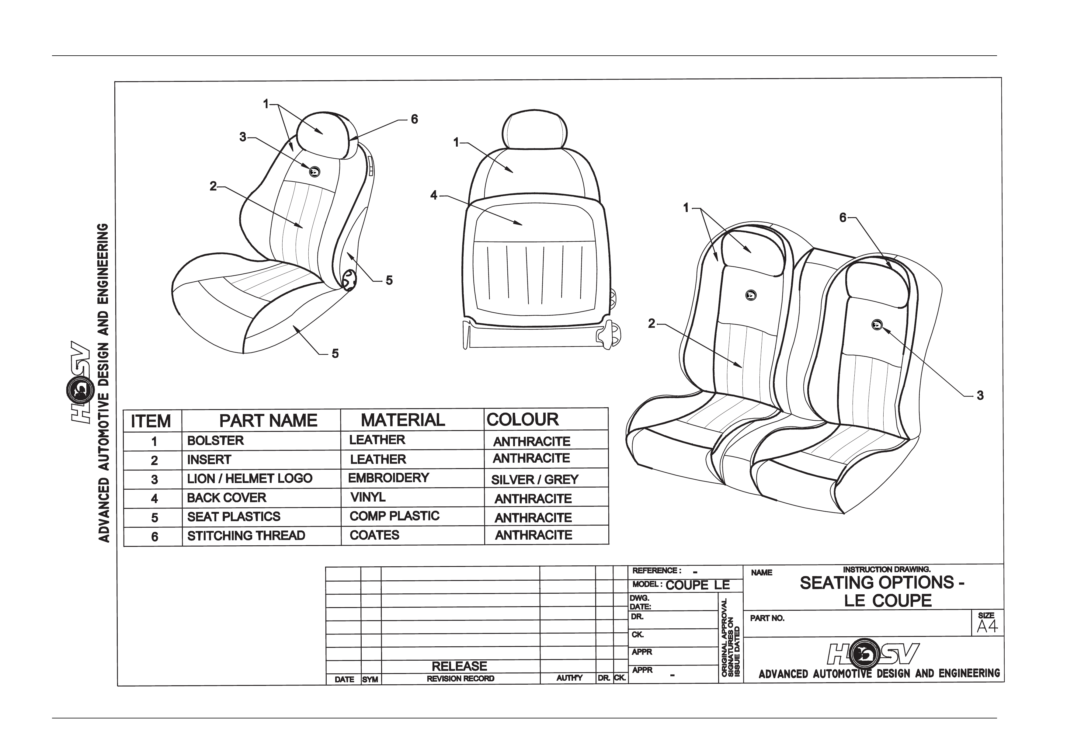
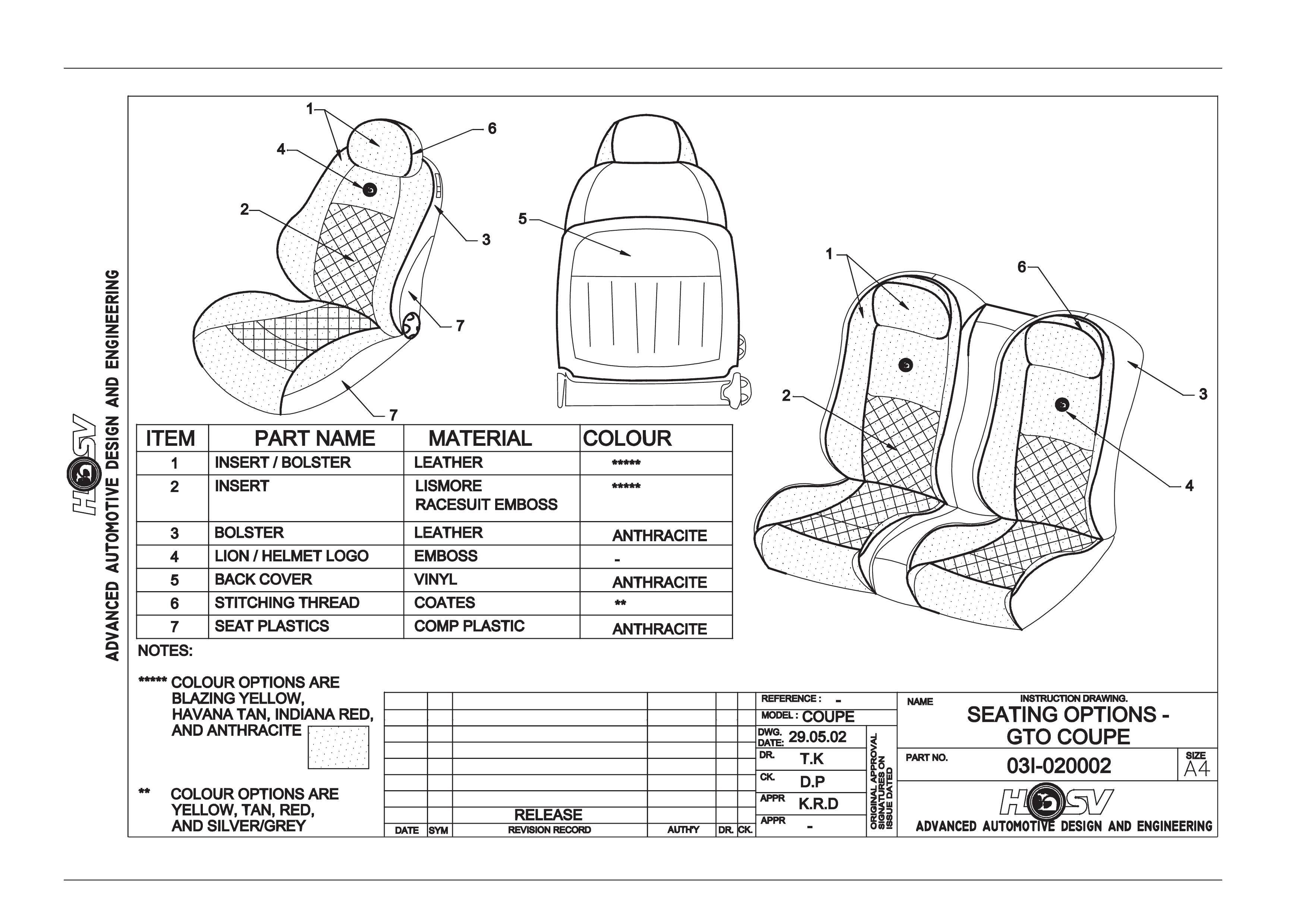
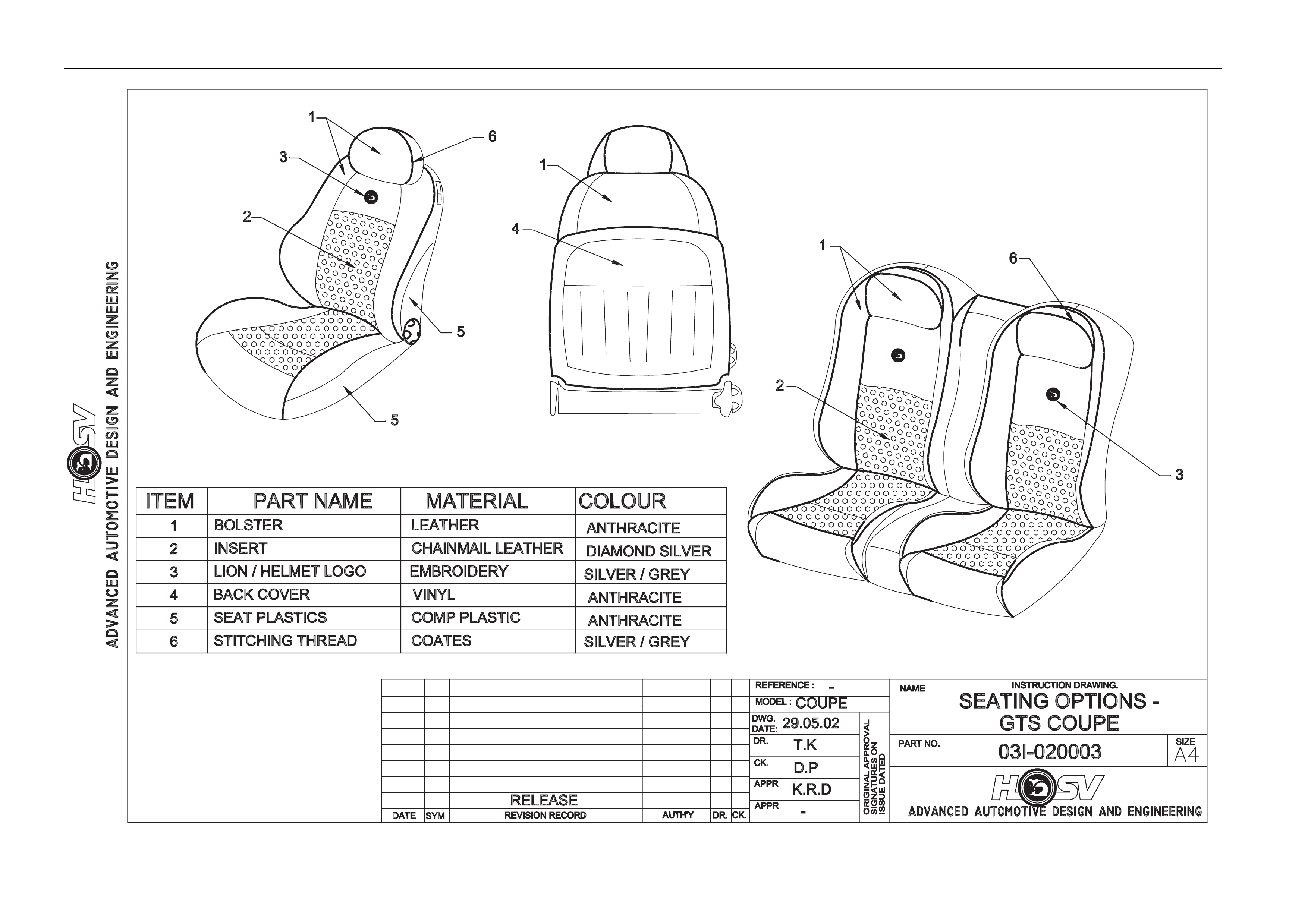
3 Seats
The HSV GTS, GTO and LE Series 3 Coupe are fitted with exclusive seat designs.
The HSV GTS, GTO and LE seats have specific seats covered in model-specific trim material.
A full range of replacement parts is available for each specific HSV seat item.

Body Page B - 5
Page B - 5
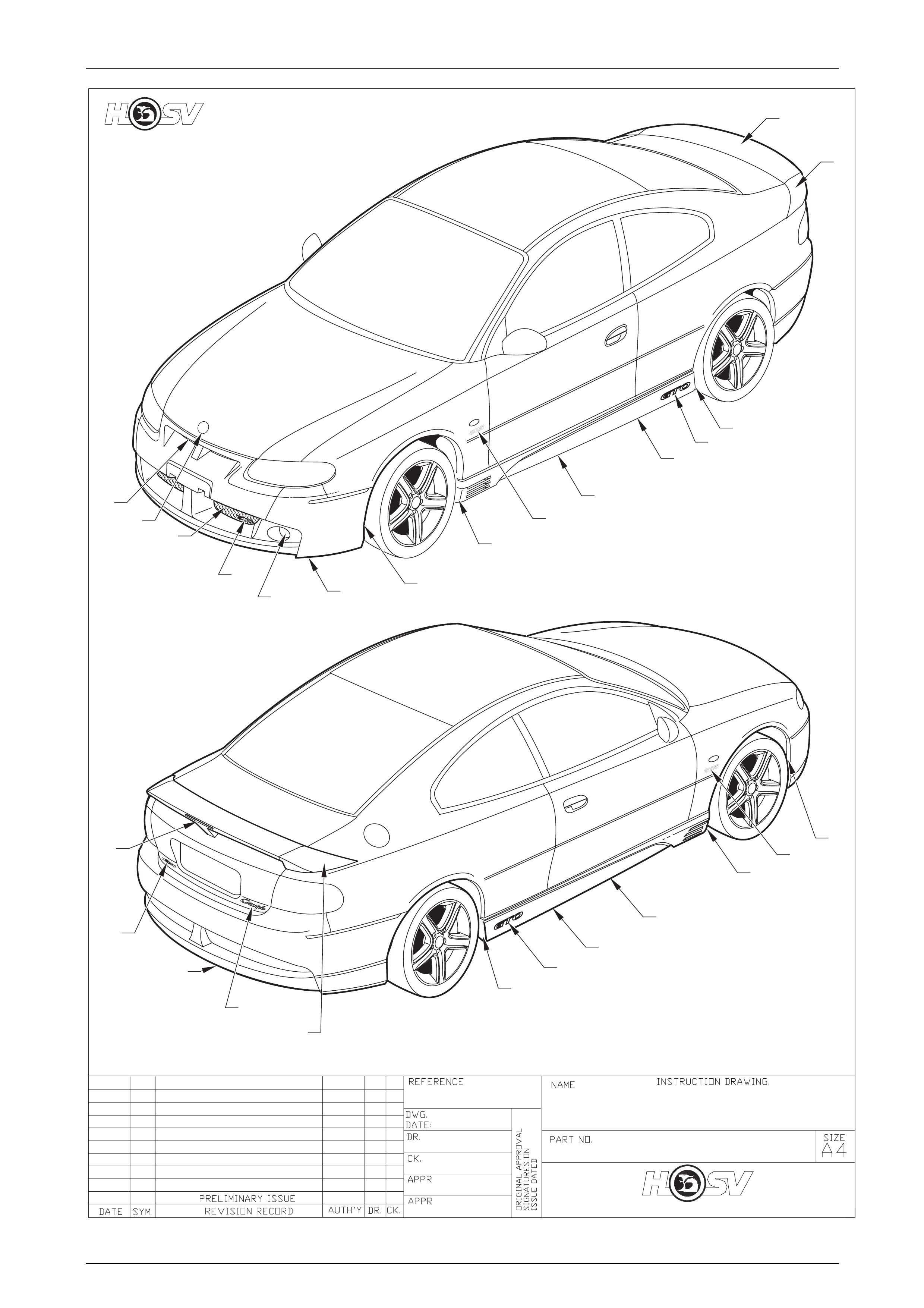
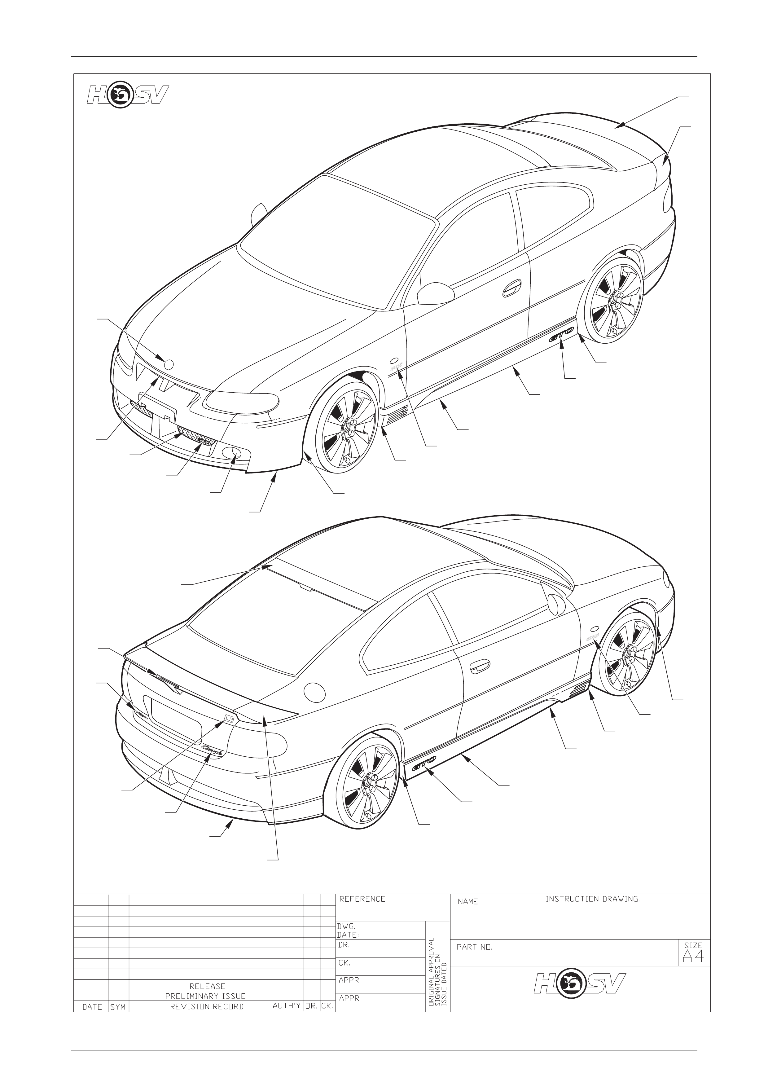
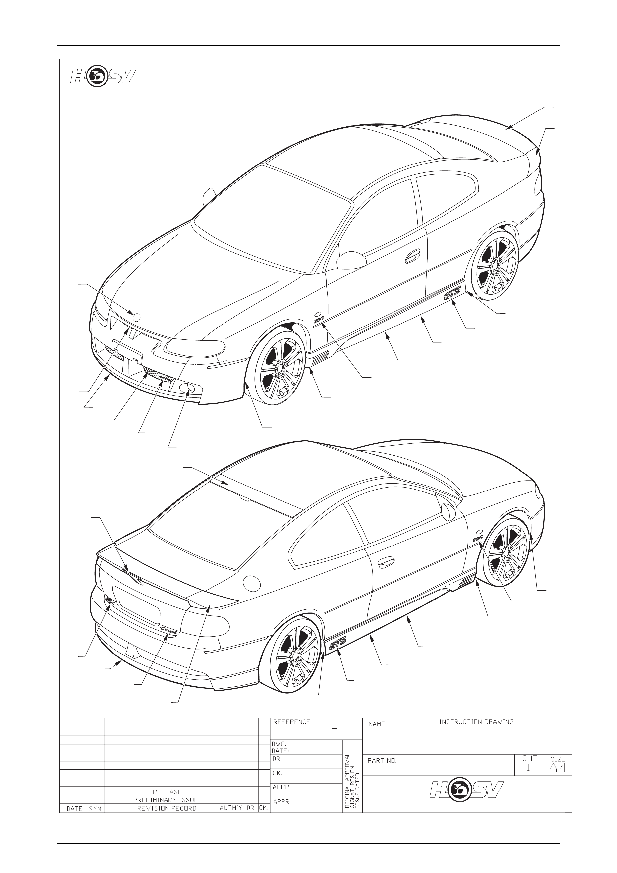
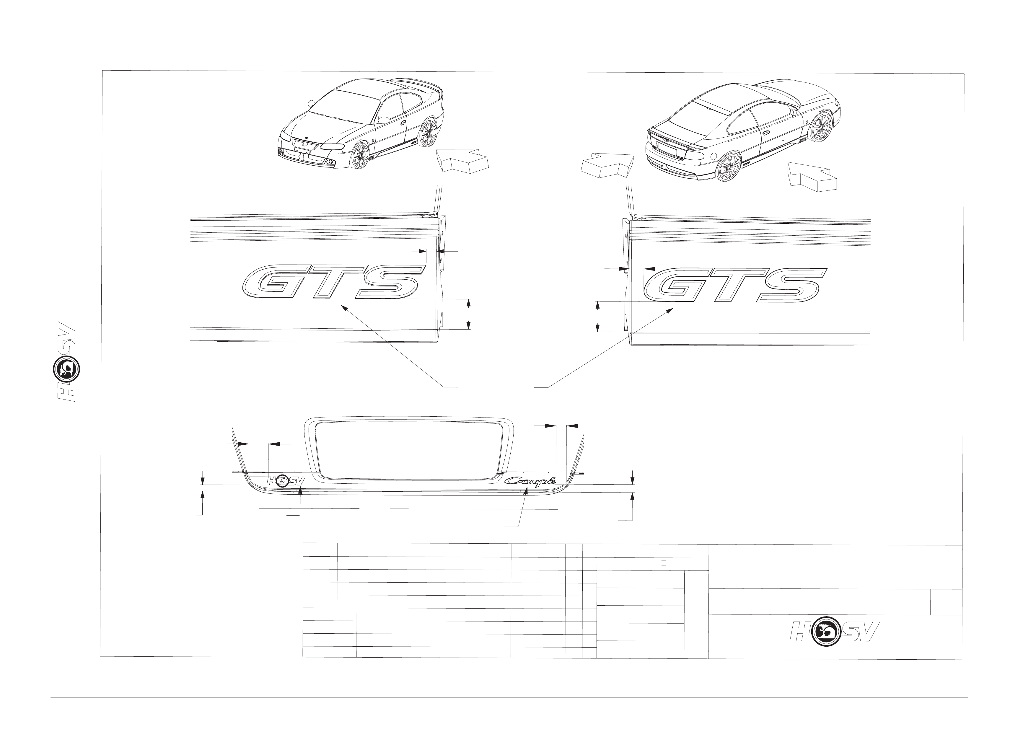
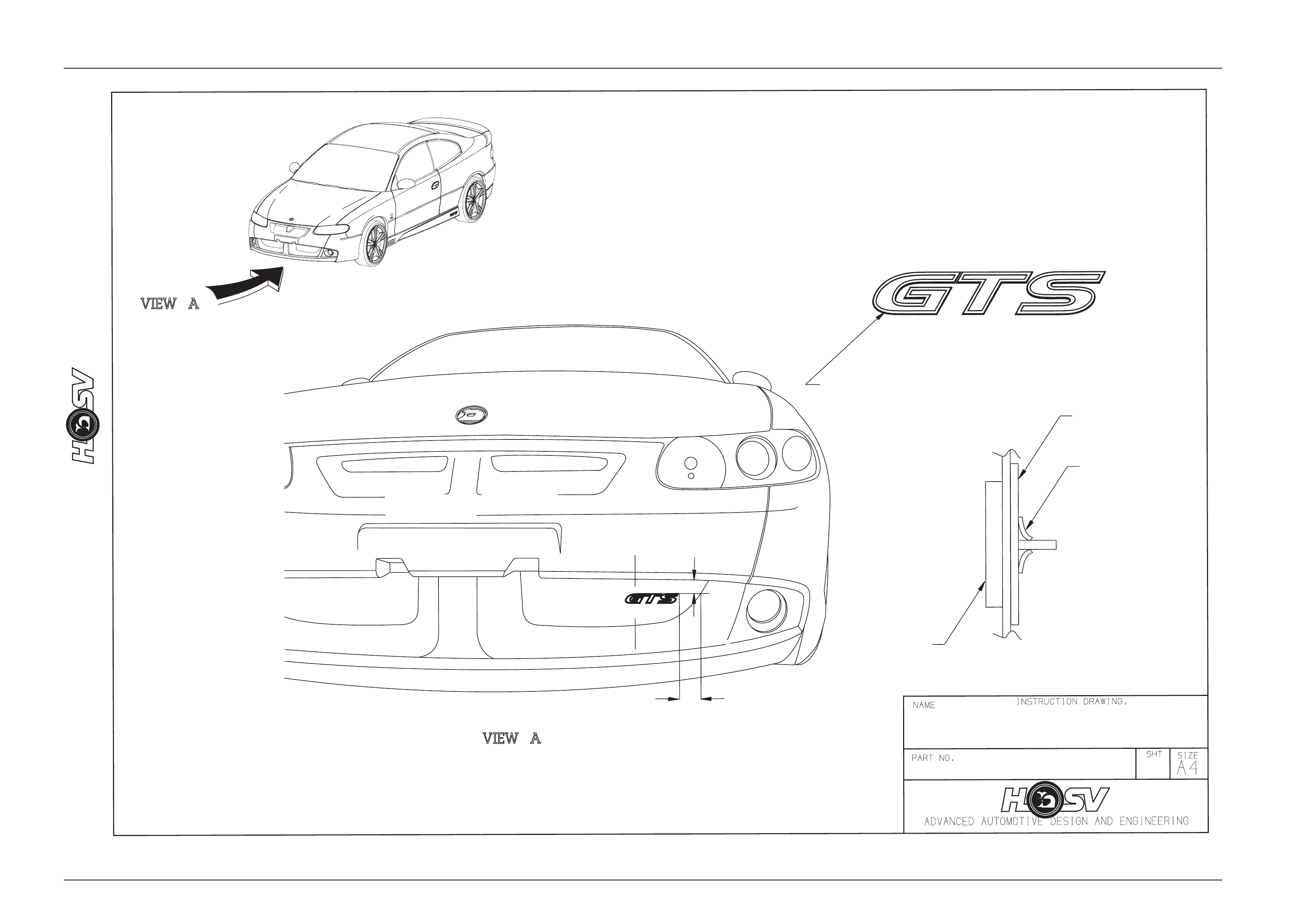
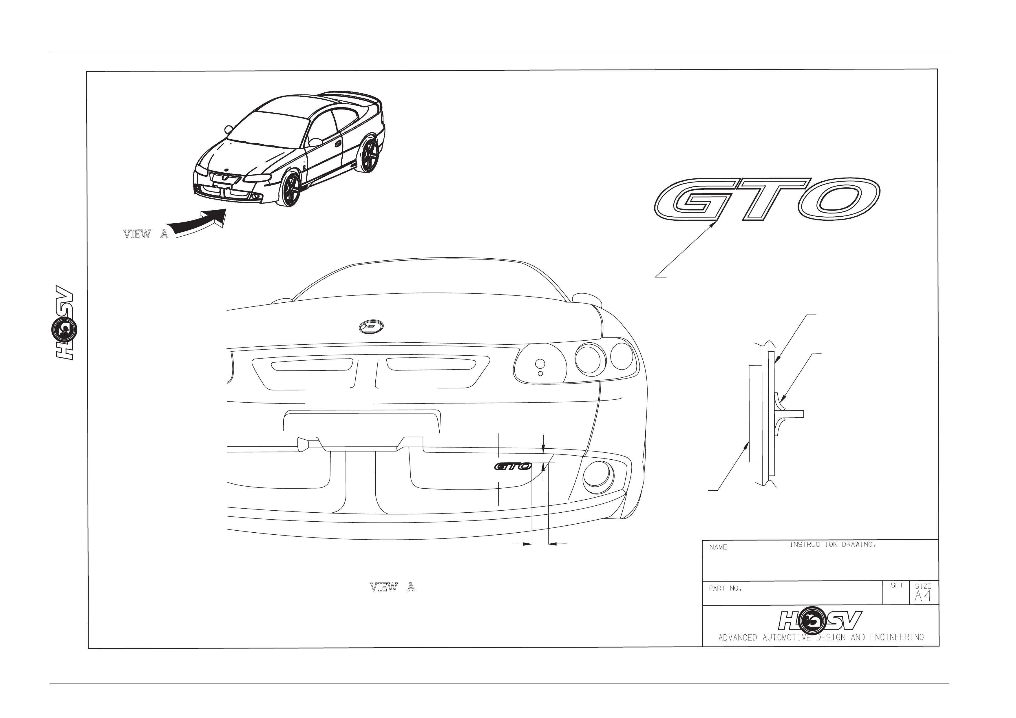
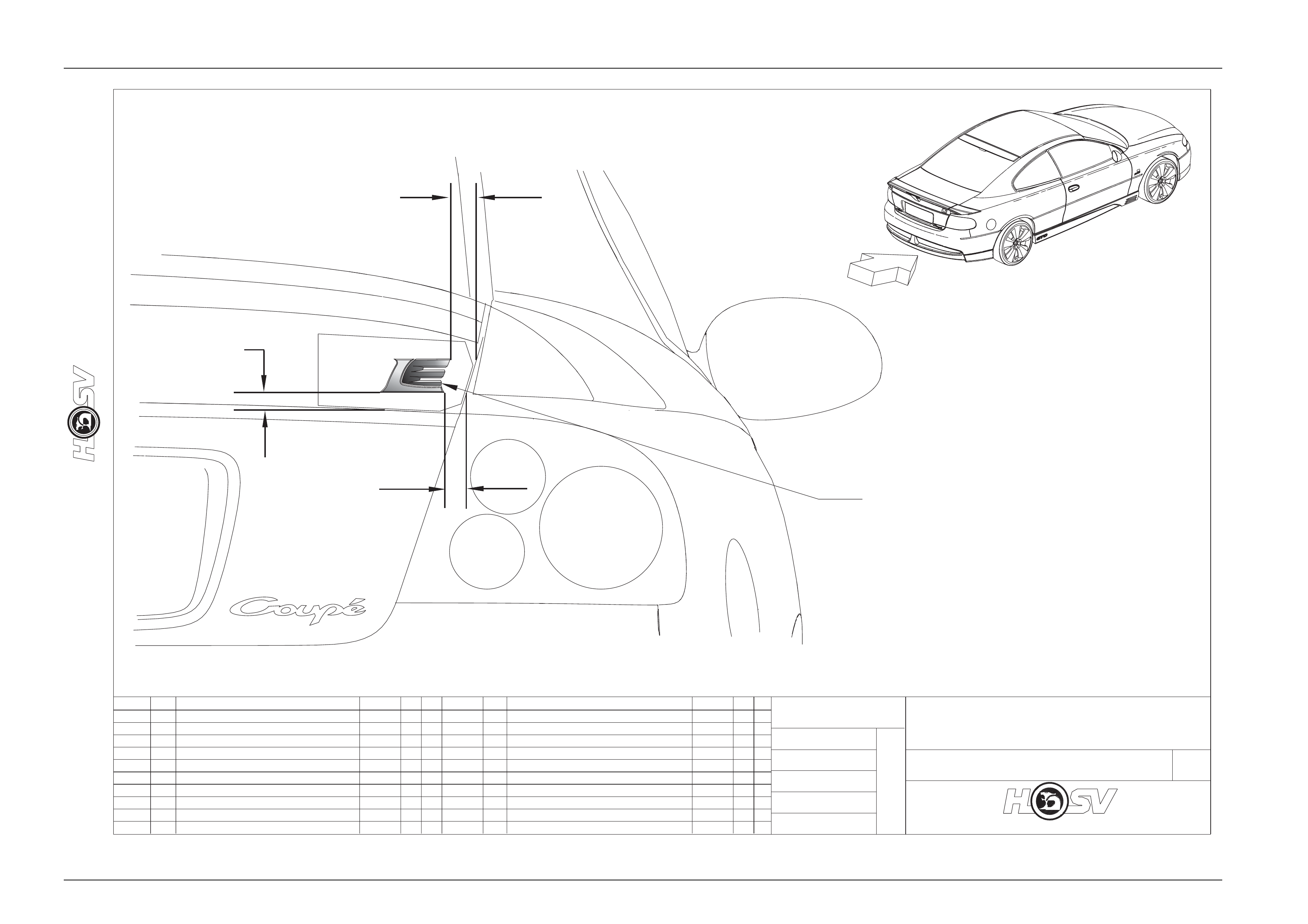
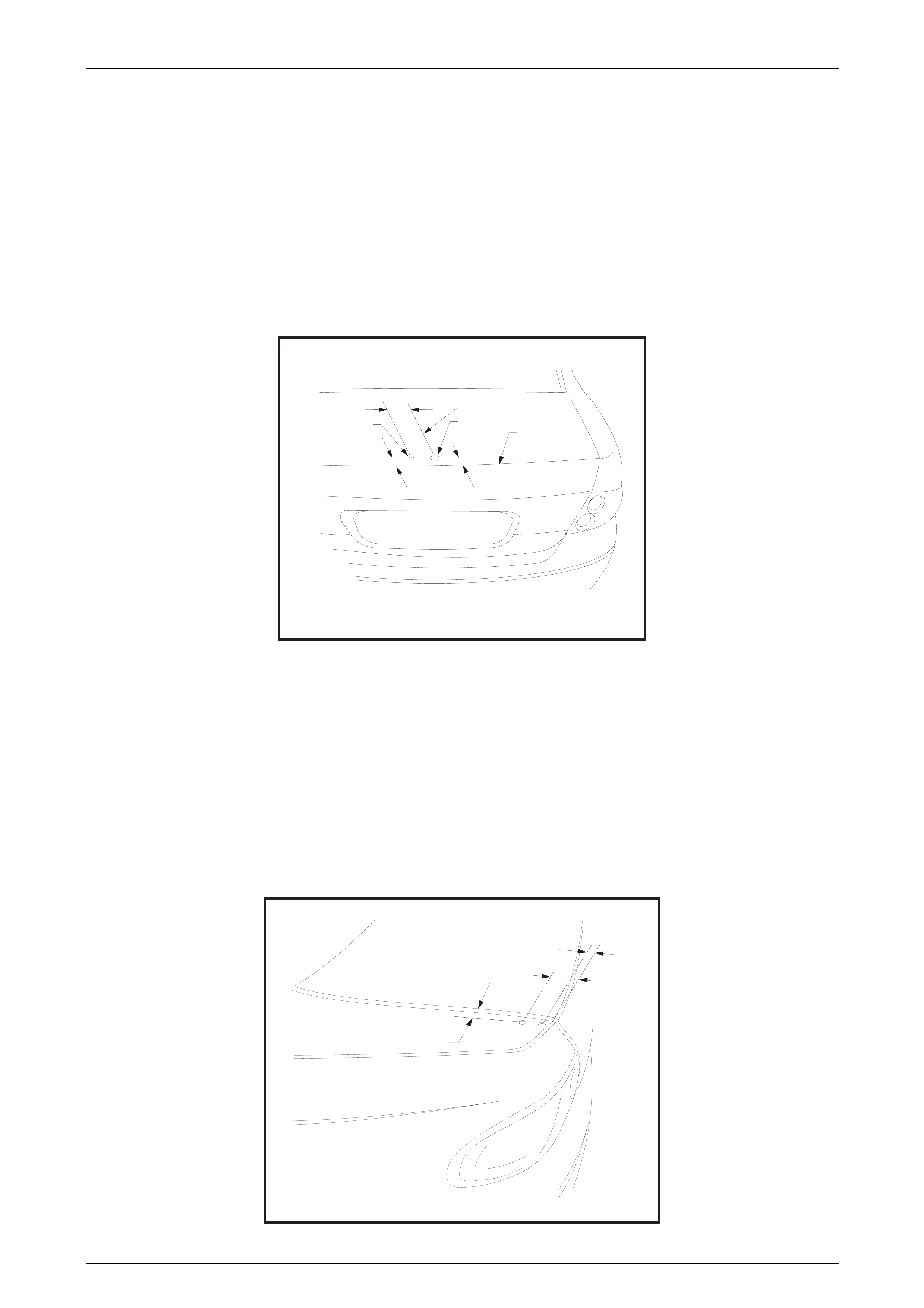
4 Body Ornamentation
HSV models are fitted with HSV specific dec als and badges to identify each model and powertrain option.
This exclusive HSV ornamentation is positioned in exact locations on each HSV model.
The ornamentation for each m odel is specified by part number in this section.
Accurate dimensions are also provided to assist with replacement of these parts.
Body Page B - 6
Page B - 6
10.12.03
AP
DP
GD
03I-030002
Body Page B - 7
Page B - 7
Body Page B - 8
Page B - 8

Body Page B - 9
Page B - 9
4.1 HSV V2 Series 3 Assembly Matrix
NOTE : J06 & K06 are HSV prefixes for front & rear components respectively.
HSV Suffixes are one letter only, and are K(NK), Y(BY), D(ID), V(HV).
E.G. Lear part 4101188BY is HSV K06-4101188Y, 4101193NK is HSV J06-4101193K
COLOUR
V2 SERIES 3 COUPE SEAT KITS
FRONT AND REAR S EAT ASM .
FRONT RH SEAT ASM.
FRONT LH
BACK
ASM.
REAR
CUSHION
ASM.
REAR
SEAT
NK (Anthricite)
ID(Indiana Red
BY(Blazing
Yellow
HV(Havana
Tan)
1 92159425 4101183 GTO (NKAnthracite) 4101186 4101185 4101187 4101188 X
2 92159426 4101189 GTO (Coloured) 4101186 4101185 4101187 4101188 X
3 92159427 4101190 GTO (Coloured) 4101186 4101185 4101187 4101188 X
4 92159428 4101191 GTO (Coloured) 4101186 4101185 4101187 4101188 X
5 92159430 4101192
GTS (Chainmail)
Middle East LHD 4101194 4101193 4101195 4101196 X
6 92159429 4101197 GTS (Chainmail) 4101198 4101193 4101195 4102296 X
7 92168370 4101205 LIMITED EDITION 4101206 4101207 4101208 4101209 X
Body Page B - 10
Page B - 10
4.2 HSV Trim Cover Assembly Matrix
NOTE : J06 & K06 are HSV prefixes for front & rear components respectively.
HSV Suffixes are one letter only, and are K(NK), Y(BY), D(ID), V(HV).
E.G. Lear part 4101188BY is HSV K06-4101188Y, 4101193NK is HSV J06-4101193K
COLOUR
V2 SERIES 3 TRIM
ASSEMBLIES
FRONT AND REAR
TRIM
ASM. FSC
TRIM
ASM.
FSB RH
TRIM
ASM.
FSB LH
TRIM ASM.
FS H/REST TRIM
ASM RSC
TRIM
ASM.
RSB RH
TRIM ASM.
RSB LH
TRIM
ASM. RS
H/REST
NK (Anthracite)
ID (Indiana Red)
BY
(BlazingYellow)
HV (Havana Tan)
1 4101183 GTO 4101227 4101228 4101229 4101201 4101230 4101232 4101231 4101088 X
2 4101189 GTO 4101080 4101200 4101199 4101202 4101085 4101222 4101223 4101097 X
3 4101190 GTO 4101080 4101200 4101199 4101202 4101085 4101222 4101223 4101097 X
4 4101191 GTO 4101080 4101200 4101199 4101202 4101085 4101222 4101223 4101097 X
5 4101192 GTS (Chainmail)
Middle East LHD 4101094 4101204 4101203 4101201 4101092 4101224 4101225 4101088 X
6 4101197 GTS 4101094 4101204 4101203 4101201 4101092 4101224 4101225 4101088 X
7 4101205 LIMITED EDITION 4101210 4101212 4101211 4101219 4101213 4101214 4101266 4101220 X

Body Page B - 11
Page B - 11
4.3 HSV Frame Matrix
V2 SERIES 3 FRAMES
FRONT AND REAR FRONT SEAT
CUSHION FRONT SEAT
BACK RH FRONT SEAT
BACK LH REAR SEAT
CUSHION REAR SEAT BACK
1 GTO 4004611 4004968 4004967 4005124 4005123
2 4101192 GTS (Chainmail)
Middle East LHD 4004611 4004966 4004967 4005124 4005123
3 4101197 GTS 4004611 4004968 4004967 4005124 4005123
4 4101205 LIMITED EDITION 4004611 4004968 4004967 4005124 4005123

Body Page B - 12
Page B - 12
4.4 HSV Pad Matrix
V2 SERIES 3 PADS
FRONT AND REAR
FRONT
SEAT
CUSHION
FRONT
SEAT
CUSHION
INSERT
FRONT
SEAT
BACK
FRONT
SEAT
HEADREST
REAR
SEAT
CUSHION
REAR
SEAT
BACK
REAR
SEAT
HEADREST
REAR
SEAT
CUSHION
INSERT
REAR
SEAT
BACK
INSERT
1 GTO 4003612 4003610 4005137 4004438 4003176 4003177 4003616 4004035 4004058
2 410119
7
GTS 4003612 4003610 4005137 4004438 4003176 4003177 4003616 4004035 4004058
3 4101205 LIMITED EDITION 4003612 4003610 4005137 4004438 4003176 4003177 4003616 4004035 4004058

Body Page B - 13
Page B - 13
4.5 Body Styling Packages
GTO Coupe Series 3
CONTENTS OF BODY STYLING PACKAGE
PART No QTY DESCRIPTIONS REF
A08-021101 1 SKIRT-ROCKER LH 1
A08-021102 1 SKIRT-ROCKER RH 2
A08-021104 1 PAINT PROTECTOR-SIDE SKIRT FRONT RH 3
A08-021103 1 PAINT PROTECTOR-SIDE SKIRT FRONT LH 4
A08-021106 1 PAINT PROTECTOR-SIDE SKIRT REAR RH 5
A08-021105 1 PAINT PROTECTOR-SIDE SKIRT REAR LH 6
A08-021110 1 PAINT PROTECTOR-SIDE SKIRT SIDE RH 7
A08-021109 1 PAINT PROTECTOR-SIDE SKIRT SIDE LH 8
E08-031108B8 1 BADGE-HSV CORPORATE LOGO 9
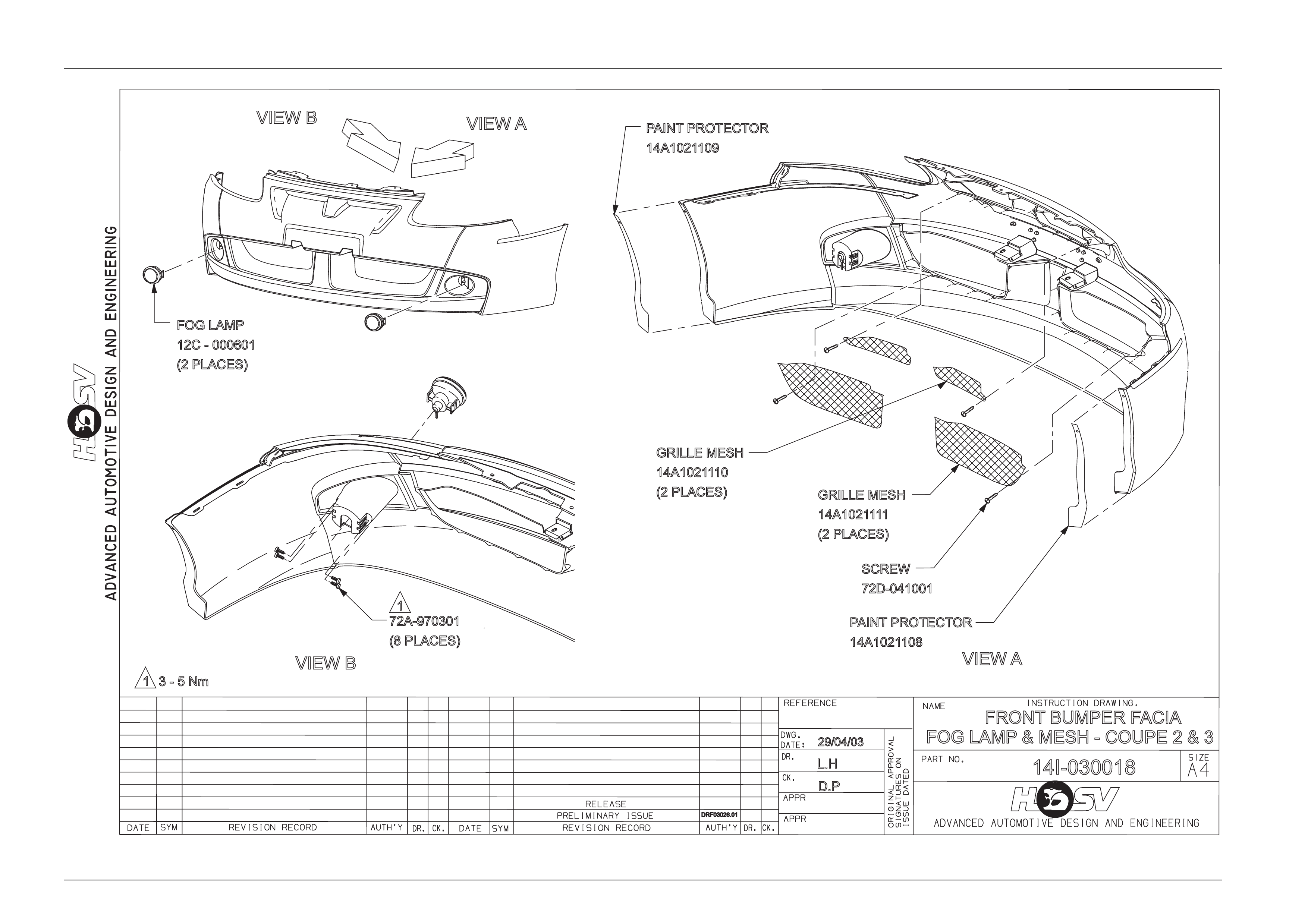
12C-000601 1 LAMP-FOG LH & RH 10
14A1021109 1 PAINT PROTECTOR-FRT LH 11
14A1021108 1 PAINT PROTECTOR-FRT RH 12
E08-020801P 1 SPOILER CENTRE DECKLID 13
E08-021103 1 SPOILER-RR DECKLID, LHS, TYPE 1 14
E08-021103 1 SPOILER-RR DECKLID, LHS, TYPE 2 14
E08-021102 1 SPOILER-22 DECKLID, RHS, TYPE 1 15
E08-021102 1 SPOILER-22 DECKLID, RHS, TYPE 2 15
14A1031101 1 FACIA-FRT BUMPER BAR 16
14A2021101 1 FACIA-RR BUMPER BAR 17
B08-020407B8 1 HOOD BADGE LION HELMET 18
E08-021105 1 BADGE-COUPE 19
E08-020609B8 1 BADGE-ENGINE ID 285 20
E08-021106 2 BADGE – GTO 21
12E-031105 1 LAMP ASM-HIGH MOUNT STOP LIGHT 22
14A1021110 1 MESH-BUMPER BAR OPENING UPPER 23
14A1021111 1 MESH-BUMPER BAR OPENING LOWER 24
13C-031101 1 BADGE-GTO, GRILLE 25
Body Page B - 14
Page B - 14
11
01.05.03
DP
LH
19
09
15
17
16
18
BODY EXTERIOR ORNAMENTATON
ADVANCED AUTOMOTIVE DESIGN AND ENGINEERING
GTO - COUPE 3
1A2F040056
07
02
21
05
12
03
20
04
01
08
06
13
14
COUPE III
DRF.03026.01
22
10
24
23 20
25
21

Body Page B - 15
Page B - 15
GTO LE Coupe Series 3
CONTENTS OF BODY STYLING PACKAGE
PART No QTY DESCRIPTIONS REF
A08-021101 1 SKIRT-ROCKER LH 1
A08-021102 1
SKIRT-ROCKER RH 2
A08-021104 1 PAINT PROTECTOR-SIDE SKIRT FRONT RH 3
A08-021103 1 PAINT PROTECTOR-SIDE SKIRT FRONT LH 4
A08-021106 1 PAINT PROTECTOR-SIDE SKIRT REAR RH 5
A08-021105 1 PAINT PROTECTOR-SIDE SKIRT REAR LH 6
A08-021110 1 PAINT PROTECTOR-SIDE SKIRT SIDE RH 7
A08-021109 1 PAINT PROTECTOR-SIDE SKIRT SIDE LH 8
E08-031108B8 1 BADGE-HSV CORPORATE LOGO 9
12C-000601 1 LAMP-FOG LH & RH 10
14A1021109 1 PAINT PROTECTOR-FRT LH 11
14A1021108 1 PAINT PROTECTOR-FRT RH 12
E08-020801P 1 SPOILER CENTRE DECKLID 13
E08-021103 1 SPOILER-RR DECKLID, LHS, TYPE 1 14
E08-021103 1 SPOILER-RR DECKLID, LHS, TYPE 2 14
E08-021102 1 SPOILER-22 DECKLID, RHS, TYPE 1 15
E08-021102 1 SPOILER-22 DECKLID, RHS, TYPE 2 15
14A1031101 1 FACIA-FRT BUMPER BAR 16
14A2021101 1 FACIA-RR BUMPER BAR 17
B08-020407B8 1 HOOD BADGE LION HELMET 18
E08-021105 1 BADGE-COUPE 19
E08-020609B8 1 BADGE-ENGINE ID 285 20
E08-021106 2 BADGE – GTO 21
12E-031105 1 LAMP ASM-HIGH MOUNT STOP LIGHT 22
14A1021110 1 MESH-BUMPER BAR OPENING UPPER 23
14A1021111 1 MESH-BUMPER BAR OPENING LOWER 24
13C-031101 1 BADGE-GTO, GRILLE 25
E08-031109 1 BADGE LE DECKLID 26
E08-021104 1 SPOILER - ROOF 27
Body Page B - 16
Page B - 16
01.05.03
DP
JD
AP
BODY EXTERIOR ORNAMENTATON
ADVANCED AUTOMOTIVE DESIGN AND ENGINEERING
GTO -LE COUPE III
1A2F030039
COUPE III
DRF.03026.01
13
14
06
11
16
18
04
01
08
10
24
23 20
25
15
20
19
09
17
07
02
21
21
05
12
03
22
26
27

Body Page B - 17
Page B - 17
GTS Coupe Series 3
CONTENTS OF BODY STYLING PACKAGE
PART No QTY DESCRIPTIONS REF
A08-021101 1 SKIRT-ROCKER LH 1
A08-021102 1
SKIRT-ROCKER RH 2
A08-021104 1 PAINT PROTECTOR-SIDE SKIRT FRONT RH 3
A08-021103 1 PAINT PROTECTOR-SIDE SKIRT FRONT LH 4
A08-021106 1 PAINT PROTECTOR-SIDE SKIRT REAR RH 5
A08-021105 1 PAINT PROTECTOR-SIDE SKIRT REAR LH 6
A08-021110 1 PAINT PROTECTOR-SIDE SKIRT SIDE RH 7
A08-021109 1 PAINT PROTECTOR-SIDE SKIRT SIDE LH 8
E08-031108B8 1 BADGE-HSV CORPORATE LOGO 9
B08-970301 1 BADGE – LION & HELMET (BONNET) 19
E08-021101 1 SPOILER – REAR DECKLID – CENTRE – TYPE1 14
E08-031101 1 SPOILER – REAR DECKLID – CENTRE – TYPE2 14
E08-021201 1 BADGE - GTS 24
12C-000601 1 LAMP FOG 10
12E-031105 1 LAMP ASM-HIGH MOUNT STOP LIGHT 25
14A1031101 1 FACIA-FRT BUMPER BAR 17
14A2021101 1 FACIA-RR BUMPER BAR 18
14A1021110 1 MESH-BUMPER BAR OPENING UPPER 26
14A1021111 1 MESH-BUMPER BAR OPENING LOWER 27
14A1021108 1 PAINT PROTECTOR – FRT RH 13
14A1021109 1 PAINT PROTECTOR – FRT LH 12
E08-021102 1 SPOILER – REAR DECKLID – RHS – TYPE1 16
E08-031102 1 SPOILER – REAR DECKLID – RHS – TYPE2 16
E08-021103 1 SPOILER – REAR DECKLID – LHS – TYPE1 15
E08-031103 1 SPOILER – REAR DECKLID – LHS – TYPE2 15
E08-021104 1 SPOILER - ROOF 20
E08-021105 1 BADGE COUPE 21
E08-020703B8 2 BADGE ENGINE ID 300 22
E08-020706B8 1 GRILLE BADGE GTS 28
Body Page B - 18
Page B - 18
01.05.03
DP
LH
BODY EXTERIOR ORNAMENTATION
ADVANCED AUTOMOTIVE DESIGN AND ENGINEERING
1A2F030017
GTS - COUPEII
COUPE II
DRF.03026.01
22 13
03
07
02
24
05
18
21
09
16
20
17
19
04
12
01
08
06
24
15
14
27
26
25
10
22
28

Body Page B - 19
Page B - 19
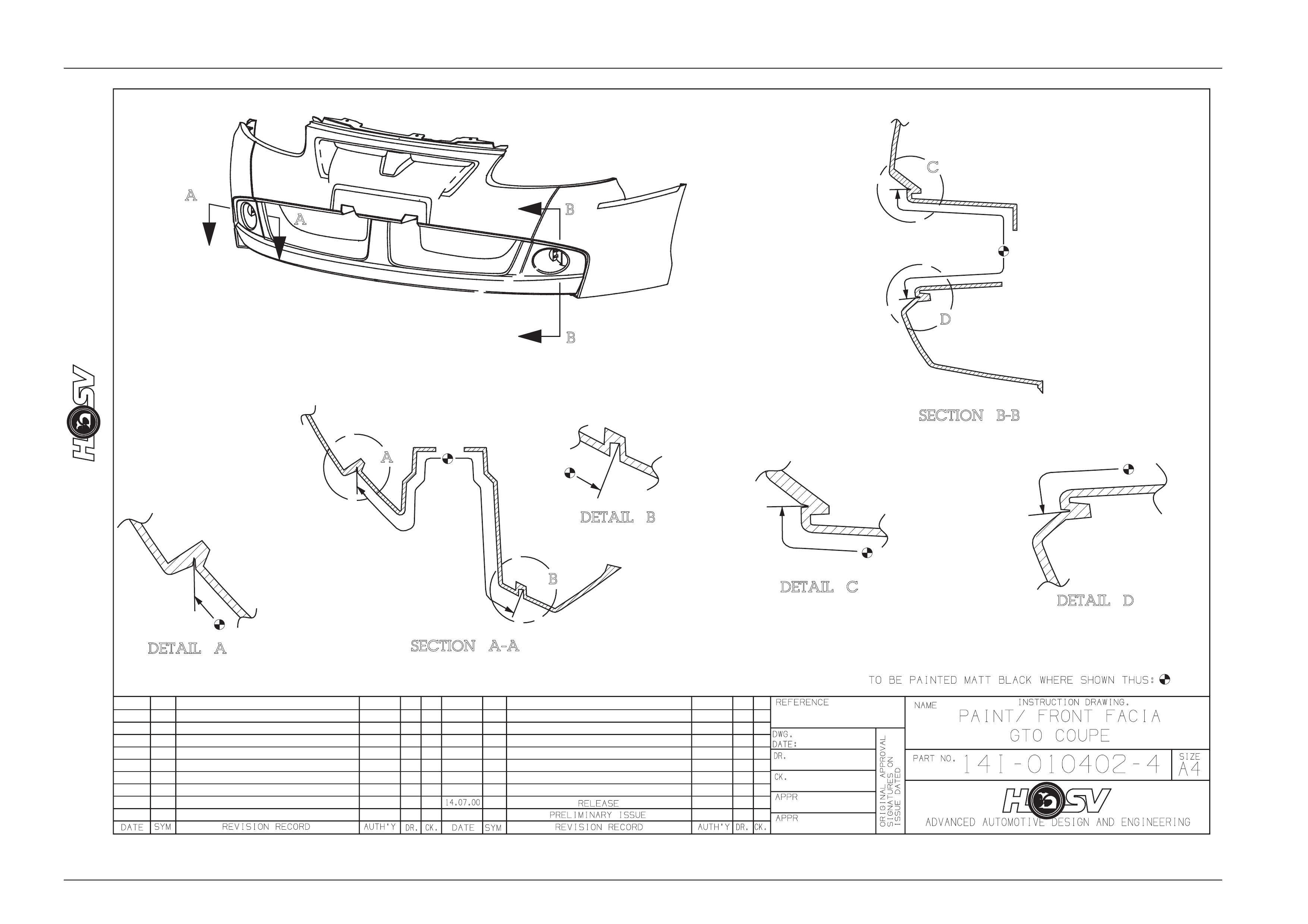
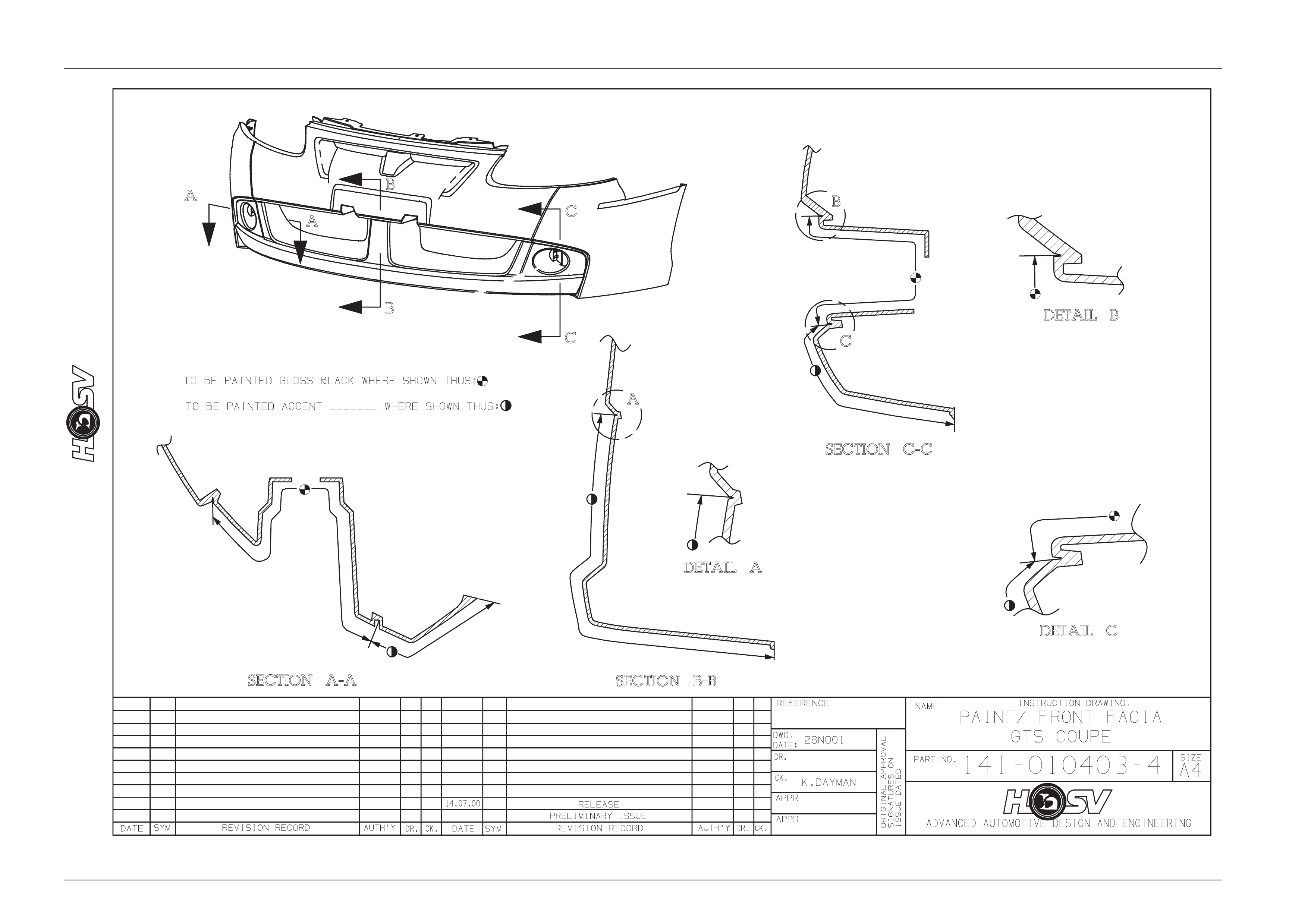
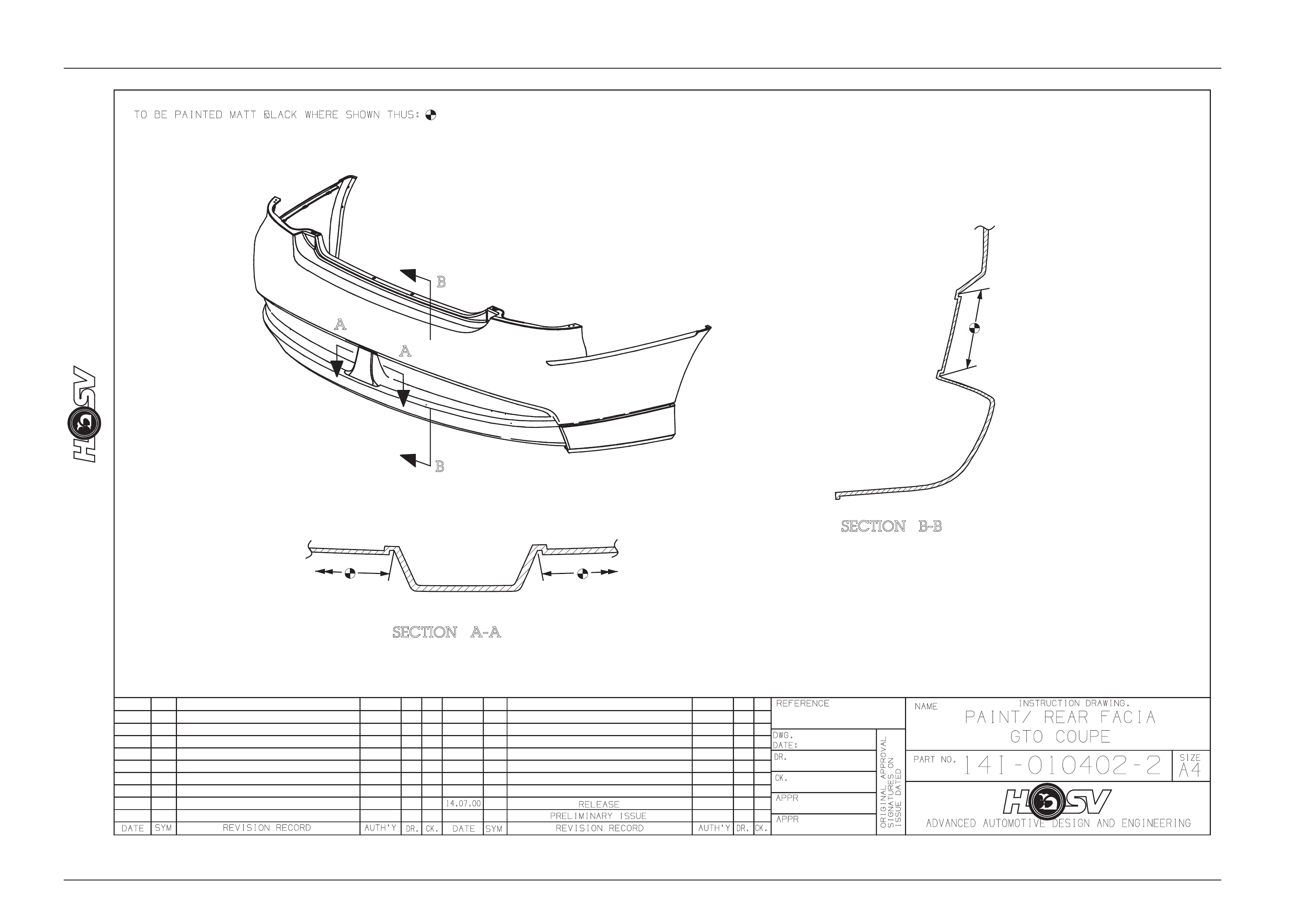
4.6 Service Information
For all body dimensions refer to Section 1A2 Body of the Holden Coupe Series Models Service Information.
For all body components not unique to HSV refer to Section 1A2 Body of the Holde n Co upe Series Models Service
Information.
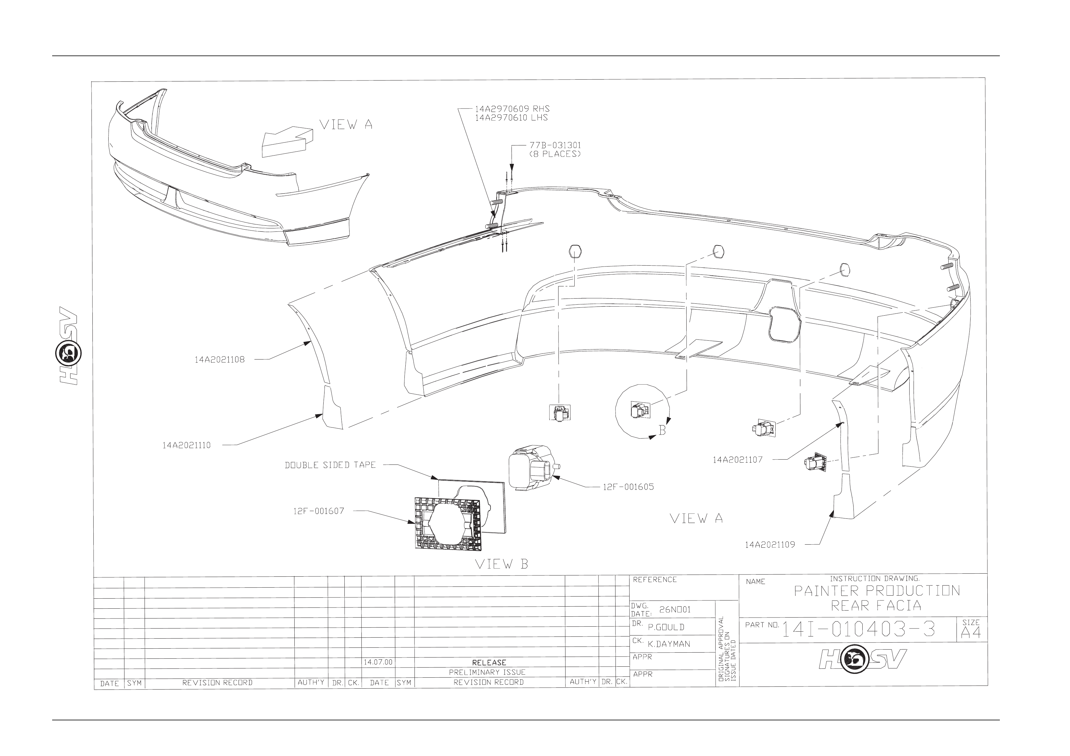
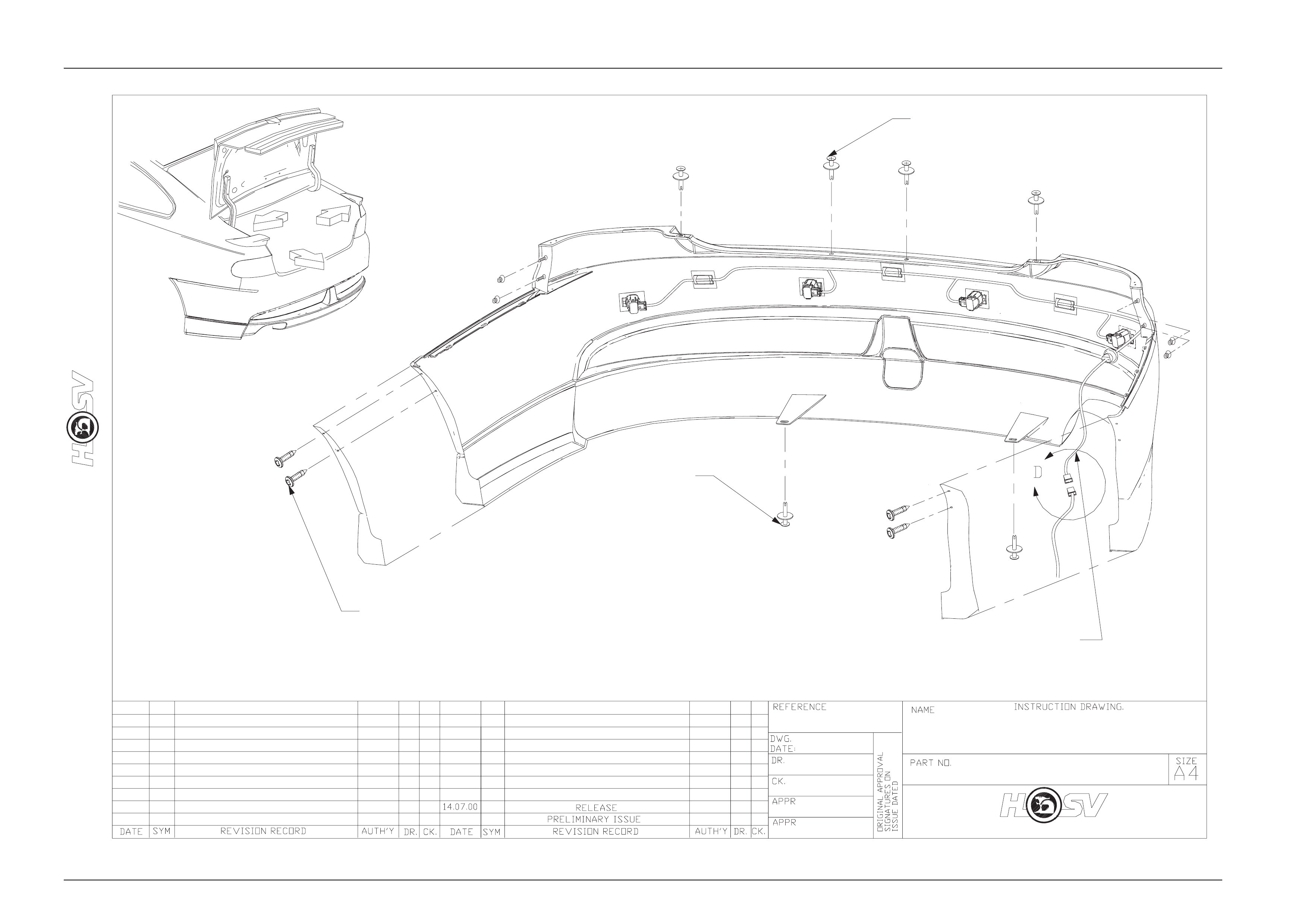
The HSV Coupe is equipped with unique Body Side Skirts, Front Bumper F acia, and 3 piece Rear Spoiler.
It is recommended that before any body repa irs be undertaken that the components involved be carefully inspected to
gain a clear understanding as to their design.
This should include attachi ng methods, assembly margins, painted features and paint accents.
Inspect the components using the relev ant HSV service instruction drawings as reference.
Where practical digital photographs can taken as required prior to work commencing, these could b e of assistance a
latter date to be used during reassembl y.
Relevant attachment tightening torque values are shown on HSV service instruction drawings. The torque locations are
defined as a number in a triangle besi de the attachment, this relates to the torque value shown on the lower margin of
the drawing.
Typical example of torque symbol location
2
Body Page B - 20
Page B - 20
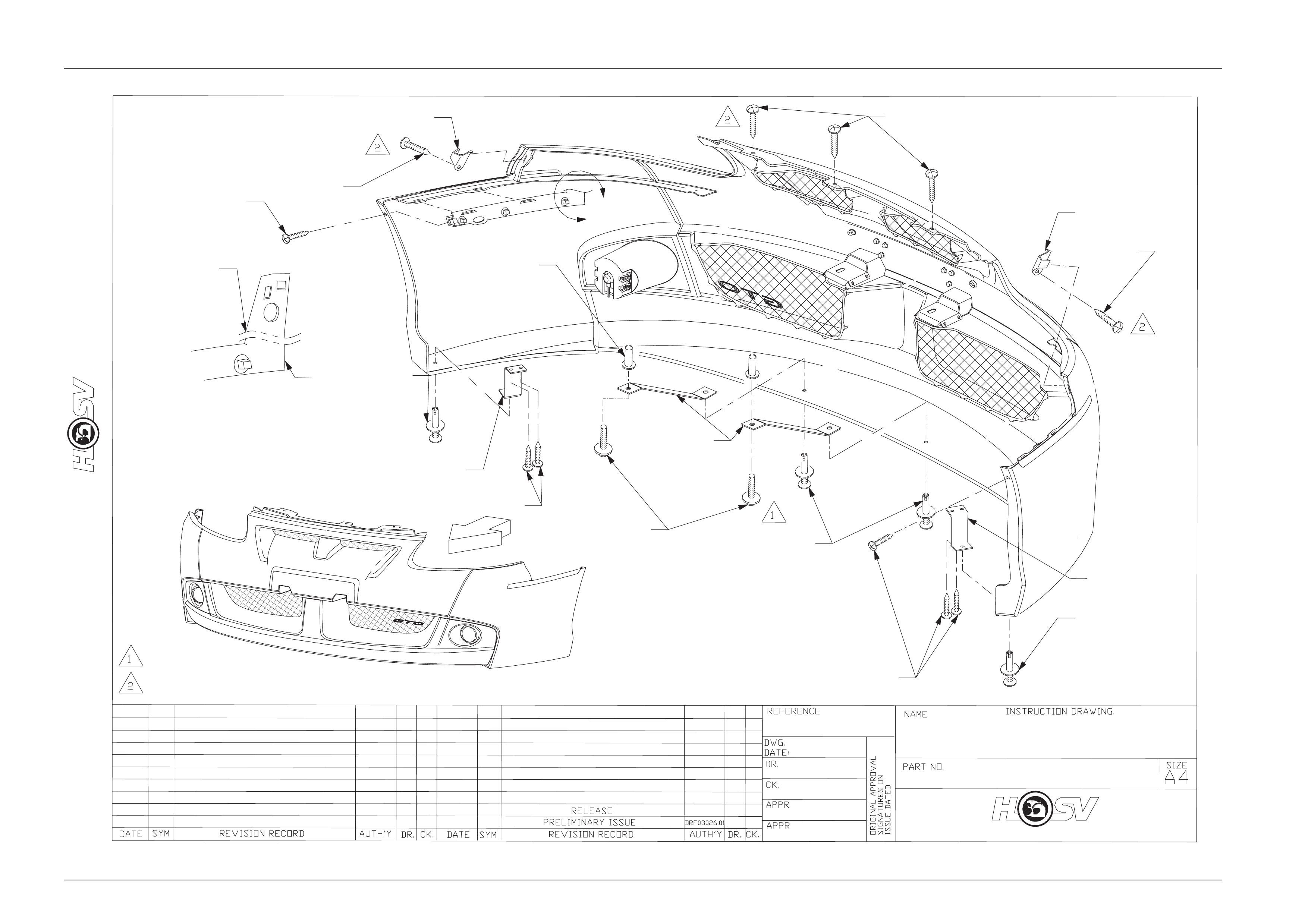
14A1021103
14A1021102
A
72D-970601
72C-671901
VIEWB
(2 PLACES)
CUT ANDREMOVE
72D-970601 B
77B-691901
(2 PLACES)
70G-060001
11072643
14A1991316
FRONT BUMPER FACIA
14I-030017
ASSEMBLYCOUPE2&3
ADVANCEDAUTOMOTIVEDESIGNANDENGINEERING
72D-970601
VIEWA
77B-691901
77B-691901
14A1011102
92138377
14A1991315
11072643
LH
DP
30/04/03
3-5Nm
3-5Nm
Body Page B - 21
Page B - 21
VIEW B
VIEW BVIEW A
D.P
VIEW A
FOG LAMP
12C -000601
(2 PLACES)
72A-970301
(8 PLACES)
PAINTPROTECTOR
14A1021109
PAINTPROTECTOR
14A1021108
SCREW
72D-041001
GRILLEMESH
14A1021110
(2 PLACES)
GRILLEMESH
14A1021111
(2 PLACES)
FRONTBUMPERFACIA
FOG LAMP &MESH-COUPE2&3
14I-030018
L.H
29/04/03
1
3-5Nm
DRF03026.01
1
Body Page B - 22
Page B - 22
ADVANCEDAUTOMOTIVEDESIGNANDENGINEERING
Body Page B - 23
Page B - 23
77B-691901
(2 PLACES)
72D-970601
(4 PLACES)
A
B
C
PRODUCTION
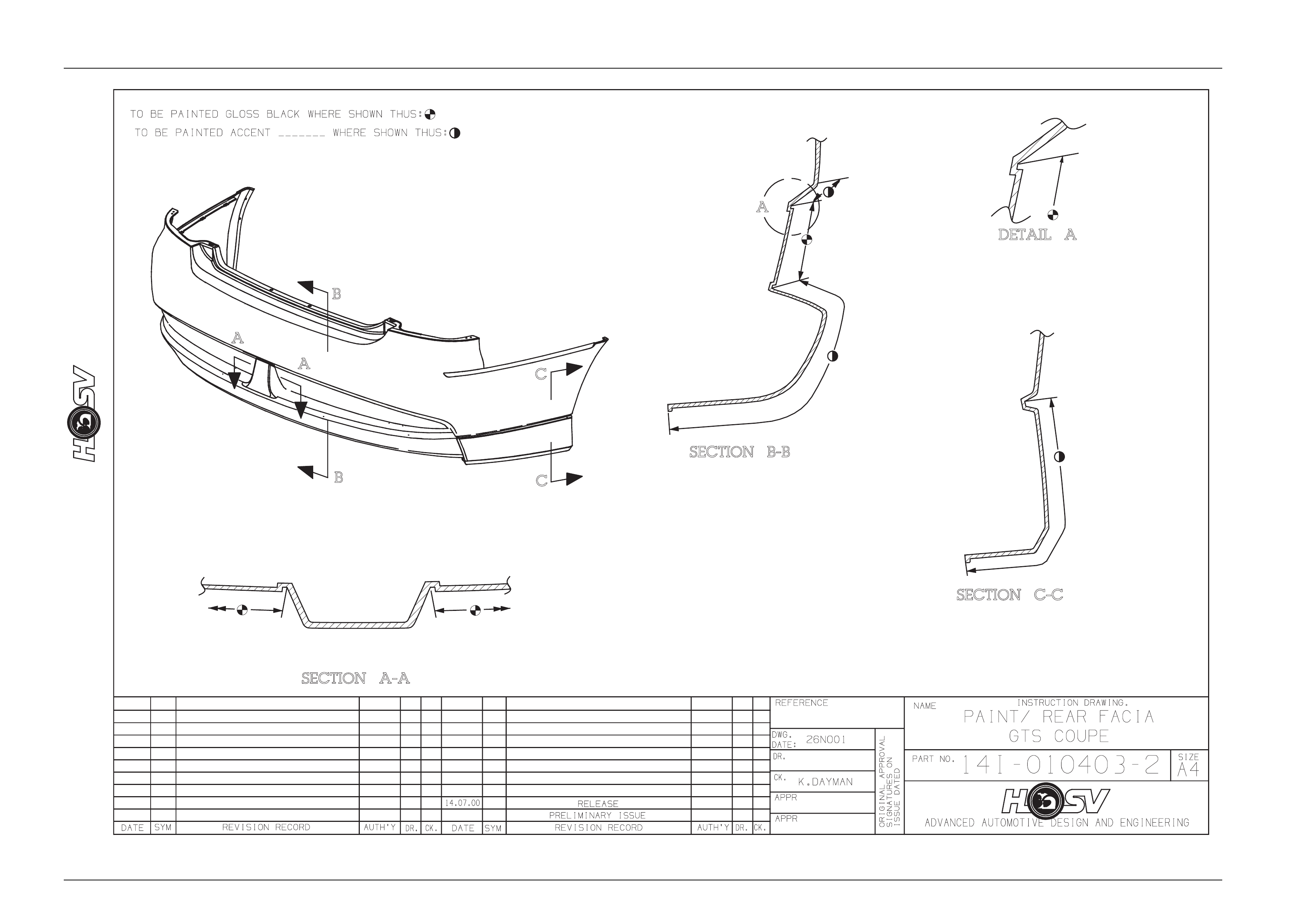
14I-010402-3
REARFACIA
ADVANCED AUTOMOTIVE DESIGN AND ENGINEERING
VIEWA
12H-011603
77B-691901
(4 PLACES)
DP
MB
LH
29/04/03
Body Page B - 24
Page B - 24
DATE
ISSUE DATEDISSUE DATED
AUTH'Y
CK.
SYM
AUTH'Y
REVISION RECORDREVISION RECORD
DATE
SYM
SIGNATURES ONSIGNATURES ON
ORIGINAL APPROVALORIGINAL APPROVAL
DR.
ADVANCED AUTOMOTIVE DESIGN AND ENGINEERINGADVANCED AUTOMOTIVE DESIGN AND ENGINEERING
1A2F-050004
INSTRUCTION DRAWING.INSTRUCTION DRAWING.
A4
SIZE
REAR FACIA
GUIDE RAILS
REAR FACIA
GUIDE RAILS
REVISION RECORDREVISION RECORD
PRELIMINARY ISSUEPRELIMINARY ISSUE
CK.
NAME
PART NO.PART NO.
CK.
REFERENCE
DWG.
DR.
DATE:
APPR
APPR
DR.
06/07/05
AP
DP
DP
VIEW
A
VIEW
B
B
A
GUIDERAILLH
14A-2031105 (HSV)
92093591(HOLDEN)
GUIDERAILRH
14A-2031106 (HSV)
92093589 (HOLDEN)
FENDER LINER RH
14A-2031108 (HSV)
92094590(HOLDEN)
FENDER LINER LH
14A-2031107 (HSV)
92094589 (HOLDEN)
Body Page B - 25
Page B - 25
DATE
ISSUE DATEDISSUE DATED
AUTH'Y
CK.
SYM
AUTH'Y
REVISION RECORDREVISION RECORD
DATE
SYM
SIGNATURES ONSIGNATURES ON
ORIGINAL APPROVALORIGINAL APPROVAL
DR.
ADVANCED AUTOMOTIVE DESIGN AND ENGINEERINGADVANCED AUTOMOTIVE DESIGN AND ENGINEERING
1A2F-050005
INSTRUCTION DRAWING.INSTRUCTION DRAWING.
A4
SIZE
REAR FENDER
LINERS
REAR FENDER
LINERS
COUPE 3COUPE 3
REVISION RECORDREVISION RECORD
PRELIMINARY ISSUEPRELIMINARY ISSUE
CK.
NAME
PART NO.PART NO.
CK.
REFERENCE
DWG.
DR.
DATE:
APPR
APPR
DR.
07.07.05
AP
DP
DP
REAR FENDER
LINER RH
14A2031108
92094590
REAR FENDER
LINER LH
14A2031107
92094589
Body Page B - 26
Page B - 26
Body Page B - 27
Page B - 27
Body Page B - 28
Page B - 28
Body Page B - 29
Page B - 29
Body Page B - 30
Page B - 30
ADVANCED AUTOMOTIVE DESIGN AND ENGINEERINGADVANCED AUTOMOTIVE DESIGN AND ENGINEERING
DATE SYM REVISION RECORD
REVISION RECORD
RELEASE
ADVANCED AUTOMOTIVE DESIGN AND ENGINEERINGADVANCED AUTOMOTIVE DESIGN AND ENGINEERING
DATE:
DR.
AUTH'Y
AUTH'Y
APPR
CK.
APPR
CK.
DR.
REFERENCE :
REFERENCE :
MODEL :MODEL :
DWG.DWG.
ORIGINAL APPROVALORIGINAL APPROVAL
ISSUE DATEDISSUE DATED
SIGNATURES ONSIGNATURES ON
PART NO.
1A2F030018
NAME INSTRUCTION DRAWING.
INSTRUCTION DRAWING.
BODY EXTERIOR ORNAMENTATIONBODY EXTERIOR ORNAMENTATION
A4
SIZE
DP
LH
02.05.03
COUPE IICOUPE II
-
-
COUPE 2 &3COUPE 2&3
60.0
20.0
15.0
E08-021201
45.0
E08-031108B8
E08-031108B8
15.0
E08-021105E08-021105
VIEWCVIEWC
VIEWAVIEWA
15.0
VIEWAVIEWA
20.0
45.0
VIEWBVIEWB
VIEWCVIEWC
VIEWBVIEWB
Body Page B - 31
Page B - 31
1
13I-030005
GRILLEBADGELOCATION
GTS -COUPE2&3
E08 -020706
GRILLEBADGE-GTS
50,0
35,0
A
ASECA-A
75E-030001
CLIP(2 PLACES)
13C -031102
RETAINER
BADGE
Body Page B - 32
Page B - 32
13I-0300041
GRILLEBADGELOCATION
GTO-COUPE2&3
13C -031101
GRILLEBADGE-GTO
50,0
35,0
SECA-A
A
A
75E-030001
CLIP(2 PLACES)
13C -031102
RETAINER
BADGE
Body Page B - 33
Page B - 33
DATE
ISSUE DATEDISSUE DATED
AUTH'YAUTH'Y
CK.
SYM
AUTH'Y
RELEASE
REVISION RECORDREVISION RECORD
DATE
SYM
SIGNATURES ONSIGNATURES ON
ORIGINAL APPROVALORIGINAL APPROVAL
DR.
14.07.00
1A2F0300401A2F030040
LEBADGELE BADGE
LE COUPE IIILE COUPE III
17.12.0317.12.03
AP
DP
GD
INSTRUCTION DRAWING.INSTRUCTION DRAWING.
A4
SIZE
BODY EXTERIOR ORNAMENTATIONBODY EXTERIOR ORNAMENTATION
REVISION RECORDREVISION RECORD
PRELIMINARY ISSUEPRELIMINARY ISSUE
CK.
NAME
PART NO.PAR T NO.
CK.
REFERENCE
DWG.
DR.
DATE:
APPRAPPR
APPRAPPR
DR.
10.010.0
27.027.0
20.020.0
VIEWAVIEWA
VIEWAVIEWA
E08-031109E08-031109
ADVANCED AUTOMOTIVE DESIGN AND ENGINEERING
Body Page B - 34
Page B - 34

Body Page B - 35
Page B - 35
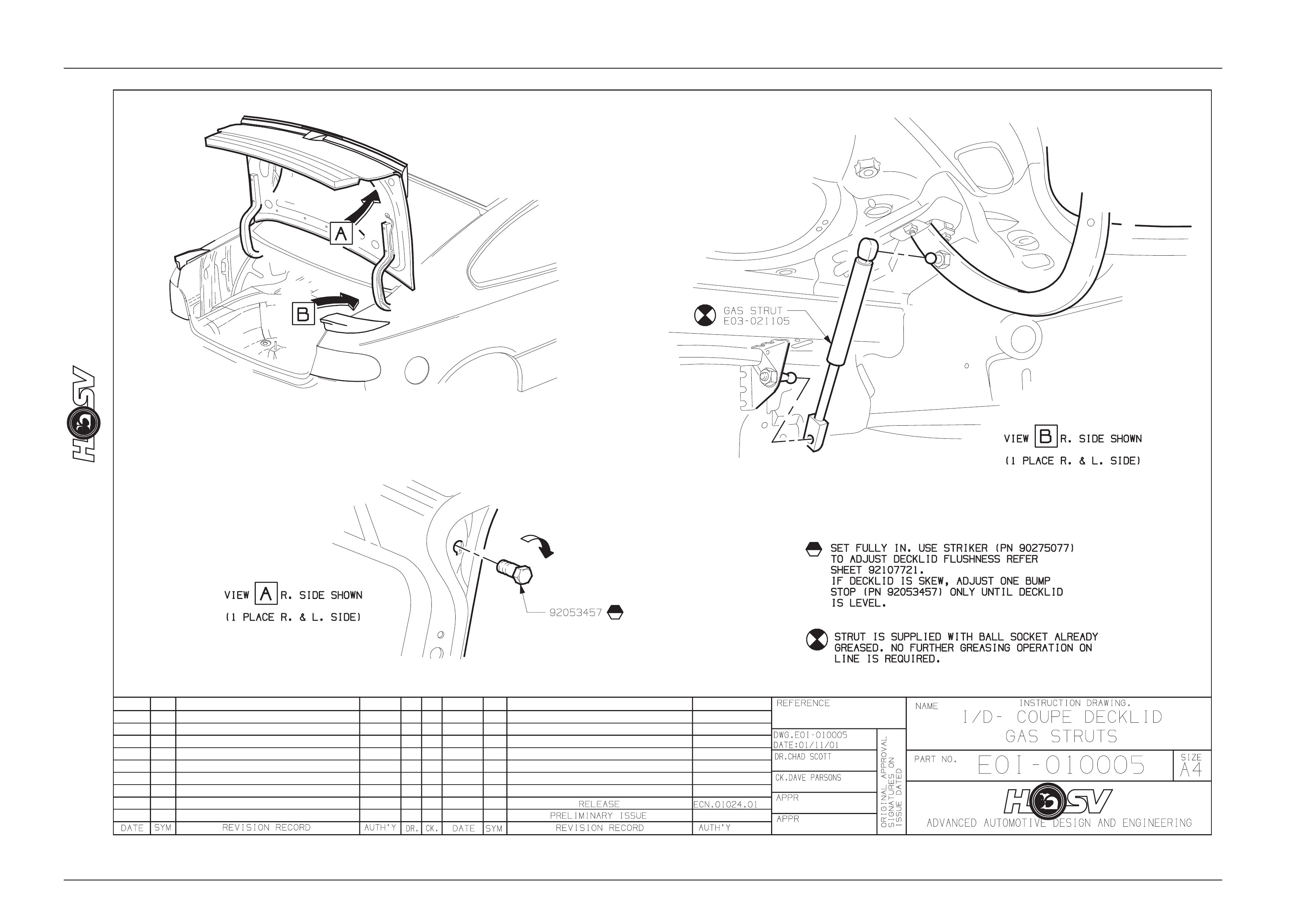
5 Rear Spoiler Type 2
ATTENTION
Before performing any service operation or other procedure described in this section refer to section 00
CAUTIONS AND NOTES for correct workshop practices with regard to safety and/or property damage.
5.1 Service Operations
Coupe built after 1. 4. 2003
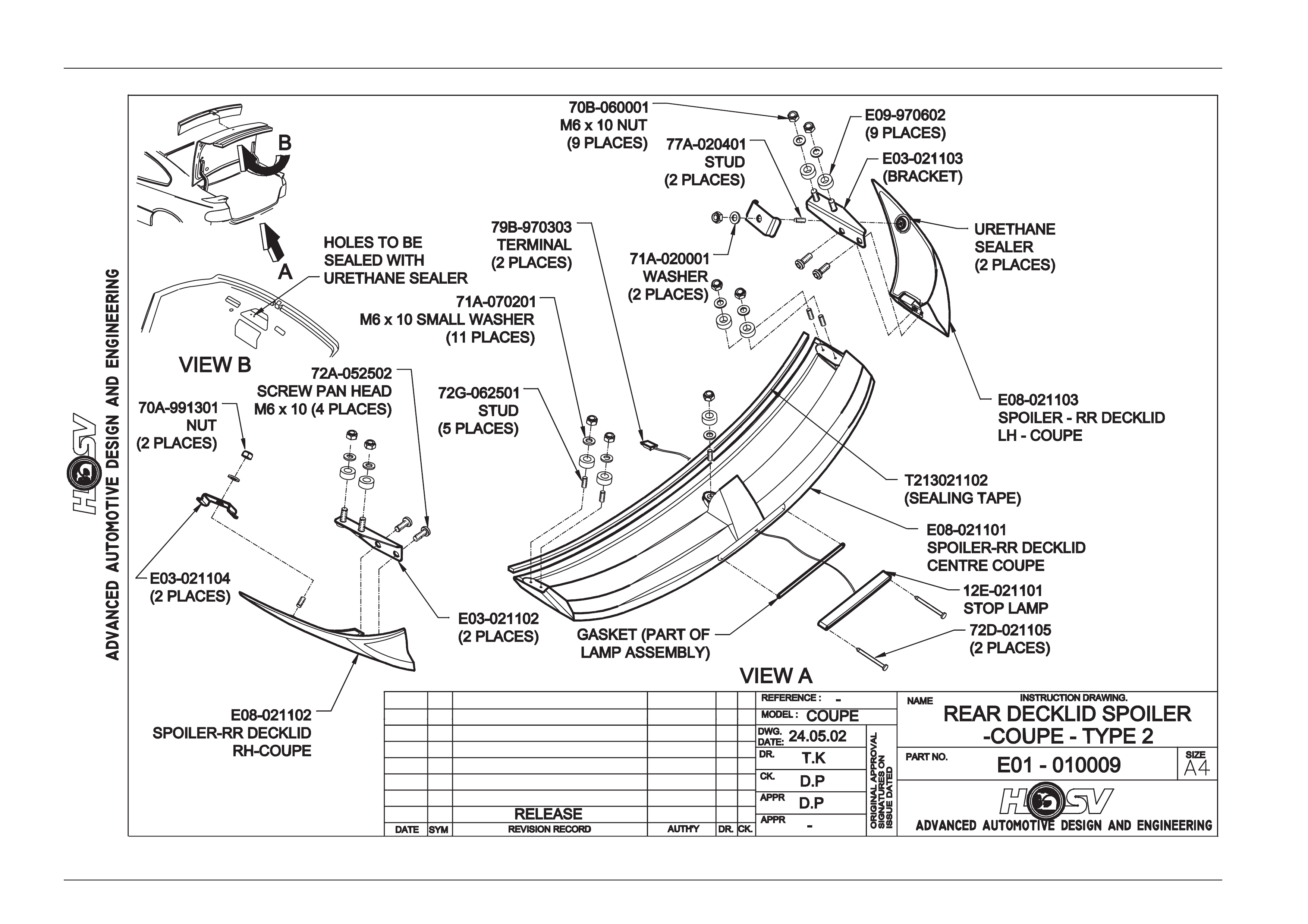
Refer to drawing E01-010009
Spoiler Ends Removal
Apply masking tape to the Rear Quarter Outer Pane l. Tape is to be located hard up against the edges of the spoiler and
to extend a width of at least 100mm around the spoiler ends;
1. Open the trunk lid;
2. Peal back to side trunk lid Rear Quarter Inner Trim to gain access to the spoiler ends front attachments;
3. Remove the attaching nut and bracket;
4. Remove the two rear upper spoiler end attaching bolts and two brackets to spoiler attaching screws and flat
washers;
5. Carefull y remove the spoiler and end from bod y work;
Spoiler Ends Installation
The installation for the spoiler ends is the rev ers of the remo val procedure.
Spoiler Centre Section Removal
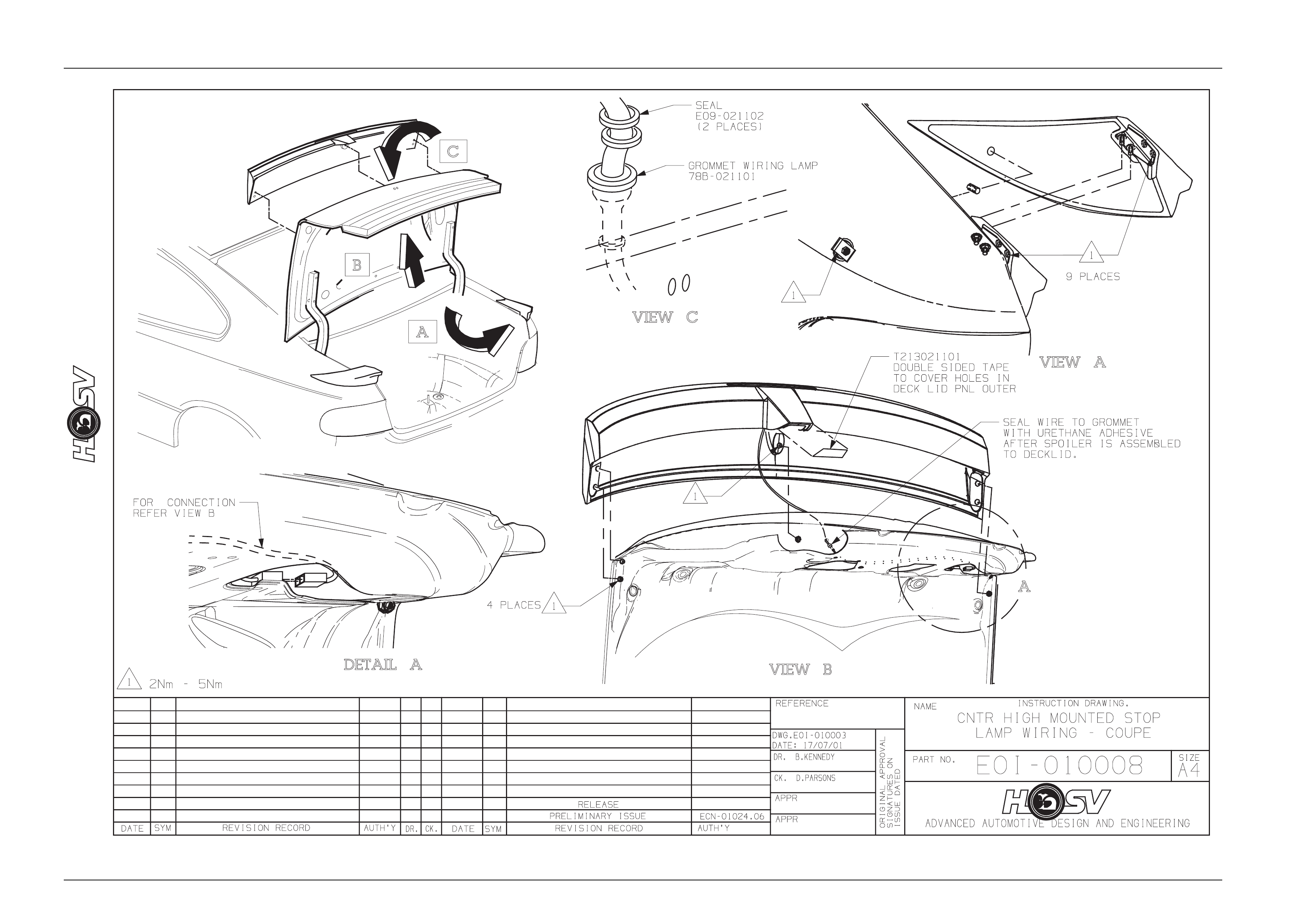
1. Remove the de ck lid inner trim;
2. Remove the ce ntre high mounted stop lamp, refer to drawing E01-010008;
3. Remove the sp oiler centre mounting flanged nut and stud;
4. Remove the four outer attaching nuts a nd washers (2 per side);
5. Remove the mounti ng studs from one side of the spoiler;
6. Carefully lift the spoiler centre from the deck lid.
Spoiler Centre Section Installation
The installation is the revers of the removal procedure. Do not attempt to install the centre spoiler with the studs installed
in the spoiler.
Body Page B - 36
Page B - 36
Body Page B - 37
Page B - 37
Body Page B - 38
Page B - 38
5.2 HSV Coupe Rear Spoiler – New Rear
Quarter Panel and New Spoiler
These instructions explain how to achieve the correct attaching hole locations for the rear spoilers when new panels are
being used and the spoilers are damaged beyo nd using as templates as pr eviously noted.
Decklid Centre Spoiler Outer Holes
Apply a 50 mm wide strip of masking tape along the outer edge of the Deck lid, both sides. The tape is to extend from the
front edge along the entire top surface.
Using a suitable pen or marker measure 18,0 mm in from the edge of the decklid and mark a line along the length of the
tape parallel to the edge.
From the front edge of the Decklid measure alo ng the line 462 mm to mark the front hole position.
Measure 20 mm in from the Decklid edge and mark a parallel lin e alo ng the last 100 mm of the Decklid top surface.
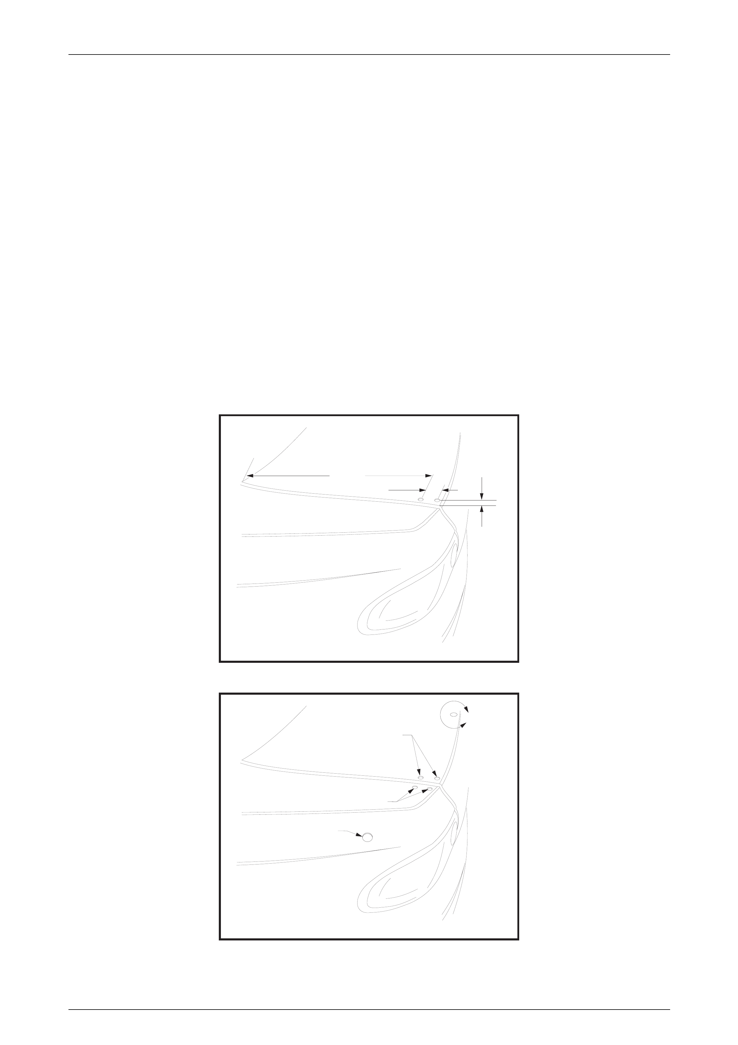
Intersect this line with a line 43 mm behind the front hole for the position of the rear hole. Refer to figure 1.
Centre punch the hole positions and carefully drill 6 mm pilot holes.
Using a step drill, open thes e holes up to 10,5 mm diameter (a 10 mm step drill produces a 10,5 diameter hole). Refer to
figure 2.
HOLELOCATIONS IN
DECK LIDOUTER PANEL
FIG1
482.0mm
43.0mm
18.0mm
DETAILOF SPOILER
ATTACHINGHOLEDIAMETERS
10.5 mm DIA.2HOLES
10.5 mm DIA.2HOLES
27.0mm DIA.HOLE
REFER TO STEP4PROCEDURE
FIG2
B
Body Page B - 39
Page B - 39
Centre Spoiler Centre Holes
Apply a 50 mm wide 100 mm long strip of masking tape in the approximate area for locatio n of the centre holes.
Working from the edges of the Decklid using a suitable pen mark the centreline of the Decklid.
From the rear edge of the Decklid measure forward 34 mm and mark the centre of the central attachi ng hole.
Draw a line parallel to and 50 mm to the right of the centerline. Intersect this line with a line 37 mm forward of the rear
edge of the Decklid for the attaching hole.
Carefully centre punch the hole positions and drill 6 mm pilot holes.
The Wiring hole is drilled to suit a 19 mm chassis punch. Refer to Figure 3
The centre attaching hole is drilled to 10,5 mm using a step drill. Refer to Figure 3
DETAILOF SPOILER
CENTRAL ATTACHINGHOLES
DECKLIDREAR
UPPER EDGE
LDECKLID
C
FIG3
37.0mm
VIEW
B
50.0mm
10.5 mm Dia Hole 20.0mm Dia Hole
34.0mm
Side Spoiler Upper Attaching Holes
Apply a 50 mm wide 100 mm long strip of masking tape in the approximate area for location of the holes.
Mark a line outboard of and p arallel to the edge of the Decklid open ing.
From the rear upper edge of the Rear Quarter Panel measure forward 31 mm and mark the rear hol e position.
From the rear upper edge of the Rear Quarter Panel measure forward 87 mm and mark the front hole positio n.
Carefully centre punch the hole positions and drill 6 mm pilot holes.
Using a step drill, open thes e holes up to 10,5 mm diameter. Refer to figure 4
HOLELOCATIONS IN TOP
OF REARQUARTER PANEL
87.0mm
31.0mm
10.5 mm
FIG4
Body Page B - 40
Page B - 40
Side Spoiler Lower Attaching Hole
This hole is located measuring along the panel from 3 known points giving an intersection point for the hol e position.
Using 2 strips of masking tape stuck with adhesive side to side prepare 4 lengths to crea te measuring strips as sho wn
on Figure 9.
Mark these strips with the dimensions shown.
STRIP A
207,0mm
207,0mm
305,0mm
305,0mm
STRIP BSTRIP B
297,0mm297,0mm
STRIP C
100,0mm100,0mm
STRIP D
FIG9
Apply a 70 mm wide 100 mm long strip of masking tape in the approximate area for locatio n of the lower hole.
Using Strip A (207 mm distance) locate the datum mark in the centre of the front upper attaching hole and with the strip
running along the panel scribe an arc onto the tape. Refer Figure 5.
STEP1
FOR LOCATION IN REAR
QUARTER OUTER PANEL
OF 27.0mm DIASPOILER HOLEFIG5
STRIPA
Body Page B - 41
Page B - 41
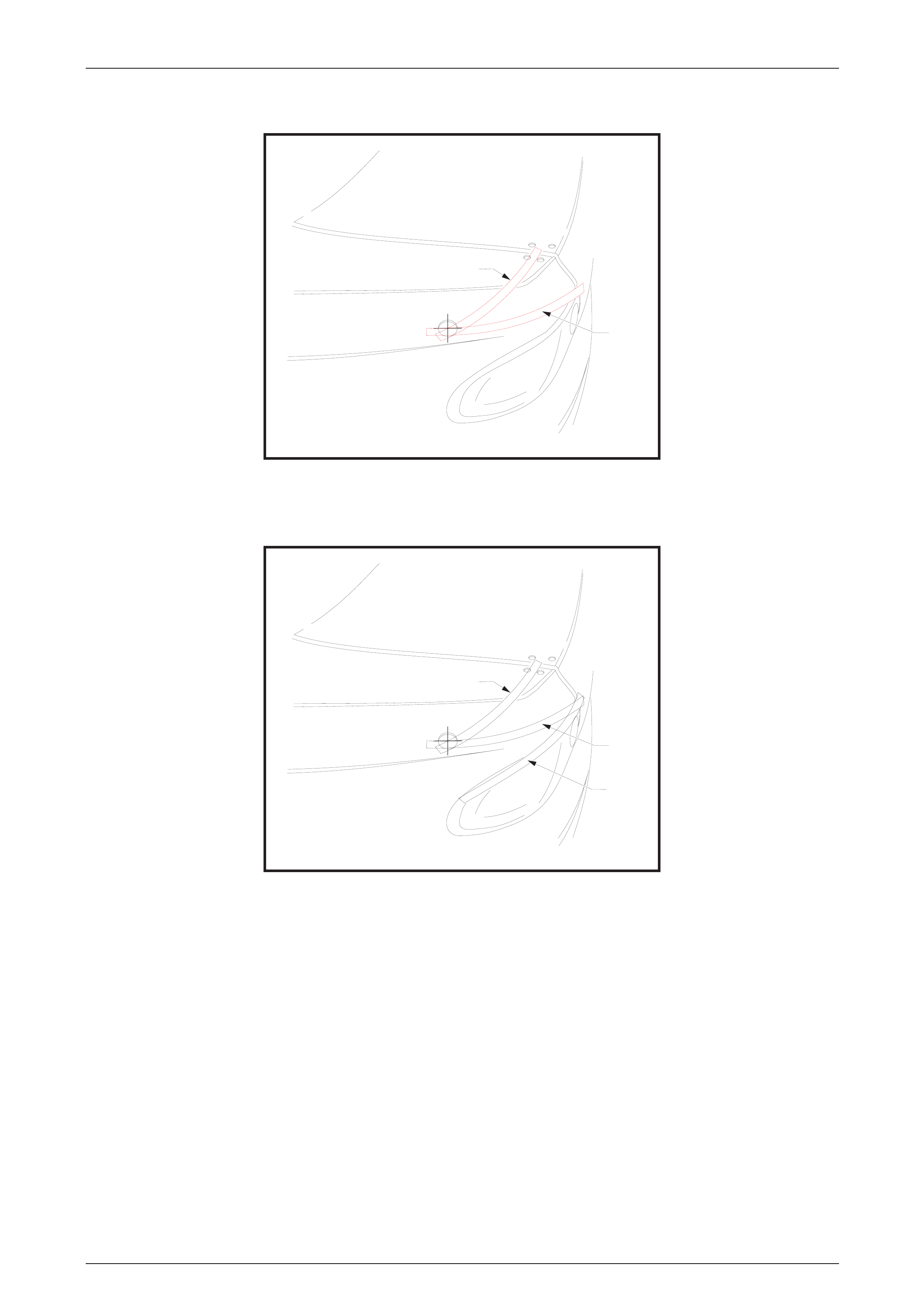
Using Strip B (305 mm distance) locate the datum mark at the intersection of the top edg e of the Tail Lamp and the Rear
Quarter Panel, with the strip running along the panel scribe another arc onto the tape. Refer Figure 6.
STEP2
FOR LOCATION IN REAR
QUARTER OUTER PANEL
OF 27.0mm DIASPOILER HOLEFIG6
STRIPA
STRIPB
Using Strip C (297 mm distance) measure along the top edge of the Tail Lamp. Mark this position on a piece of tape
located at this position. Refer Figure 7.
STEP3
FOR LOCATION IN REAR
QUARTER OUTER PANEL
OF 27.0mm DIASPOILER HOLEFIG7
STRIPA
STRIPB
STRIPC
Body Page B - 42
Page B - 42
Using Strip D (100 mm distance) locate the datum mark at the point previ ously measured along the Tail Lamp upper
edge, with the strip running al ong the panel scribe a third arc onto the tape this is a confirmation of the previous arcs.
Refer Figure 8
STEP4
FOR LOCATION IN REAR
QUARTER OUTER PANEL
OF 27.0mm DIASPOILER HOLE
FIG8
STRIPA
CENTRE PUNCH ANDDRILL
8.0mm PILOT HOLE
STRIPB
STRIPC
STRIPC
Carefully centre punc h the hole position and drill 6 mm pilot hole.
Drill the pilot hole to suit the bolt on a 26,0 mm chassis punch.
Punch the hole to 26,0 mm.
De-burring and Anti-corrosion Treatment
All holes must be de-burred prior to anti-corrosion treatment.
All holes must be treated with Zink-Rich Prim er, allow primer to cure and then paint the holes car co lour automotive
touch up paint prior to final assembly.
Sealing
Once all spoiler components are in place ensure the seals cover the mounting holes.
General Precaution
Cover all components inside the rear com partment to protect against ingress of drilling swarf and dust.
All parts of the spoiler (center and sides) are to be temporarily attached to the vehicle in position with masking tape while
preliminary fitment check is completed.
Check the gaps and alignment of the 3 spoiler components at all assembly stages of this procedure.

Body Page B - 43
Page B - 43
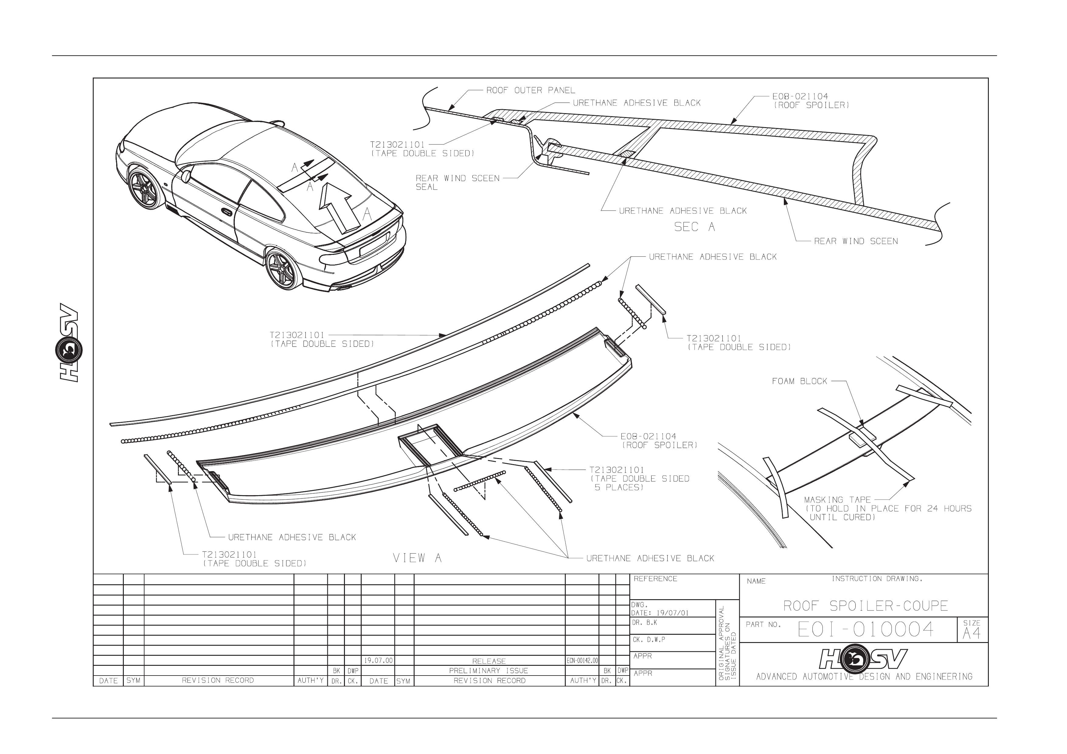
6 Roof Spoiler (LE & GTS only)
ATTENTION
Before performing any service operation or other procedure described in this section refer to section 00
Cautions And Notes for correct workshop practices with regard to safety and/or property damage.
6.1 Service Operations
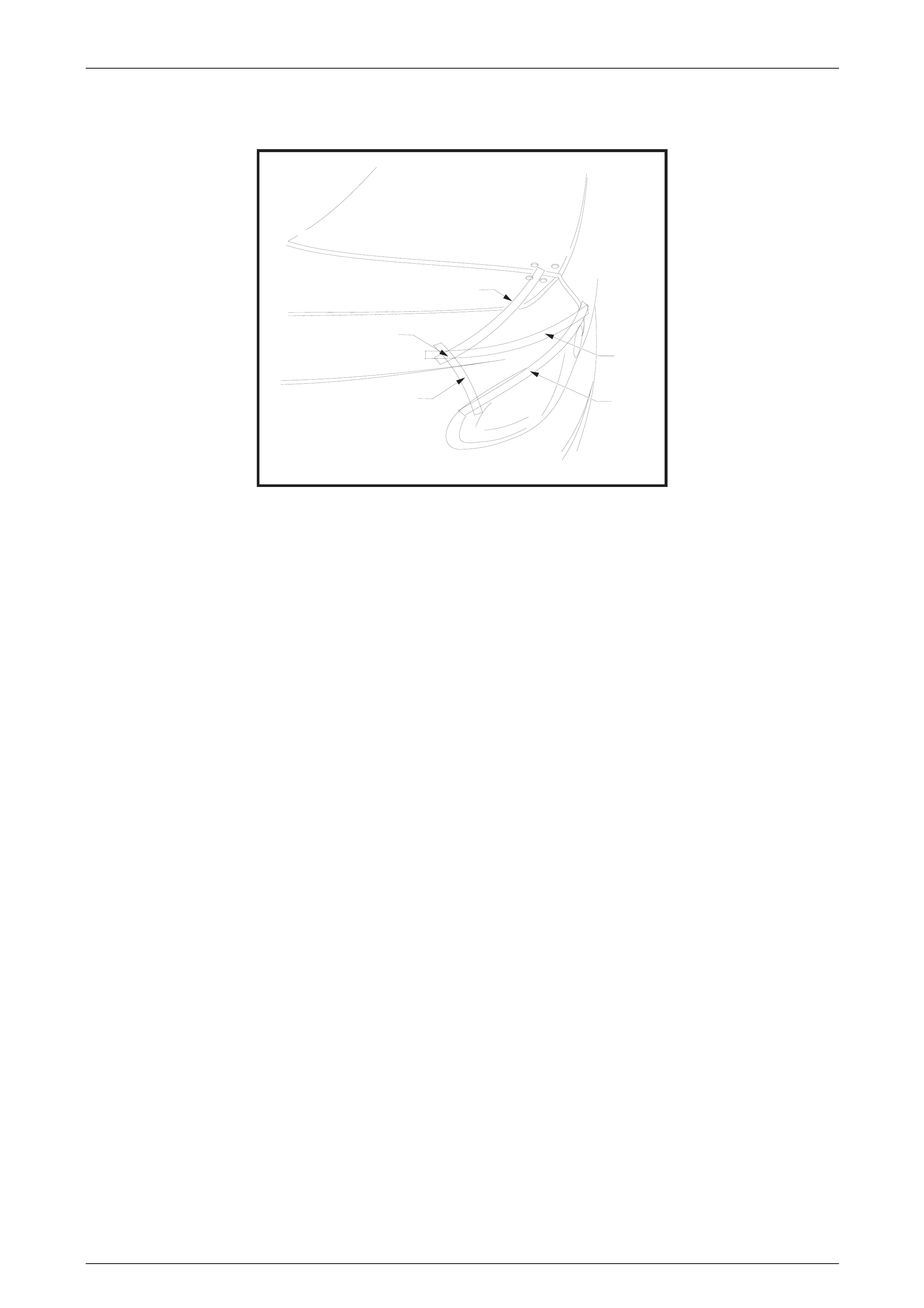
Roof Spoiler Removal
NOTE.
The roof spoiler is adhered to both the rear
window glass and the rear of the rear outer panel
with urethane adhesive. Care must be taken not
to damage the paintwork of the vehicle when
performing this operation.
1. Apply masking tape up aga inst the front and side edg es of the roof spoiler. The tape must extend for a distance of
at least 75mm away from the edges of the spoiler. This tape is to protect the roof and the rear quarter panels from
damage when removing the s poiler and adhesive;
2. Slide a body filler applicator or similar stiff plastic plate between the spoiler and the body panels. Using a cutting
action like a knife break the urethane adhesive bond. The cutting will need to be done acr oss the roof panel, down
the sides of the glass and also the glass in th e centre of the spoiler. The spoiler may be p ulled away from the panel
to access the urethane, but extreme care must be taken to avoid damage to both panels and the paintwork.
3. Clean the excess urethane off the glass and panel work with a Profit wheel, decal removing wheel or similar
implement. Extreme care mus t be taken to avoid damage to the panels and the paintwork.
Roof Spoiler Installation
1. Remove the protective masking tape used in the remova l procedure;
2. Clean the attaching area with uret hane cleaner and prime th e contact area;
3. With the assistance of another person locate the spoiler centrally between the roof mouldings (at the sides of the
rear glass) and align the spoiler side n otches (located towards the top of the edge of the spoiler) with the top rear
window glass moulding;
4. Using a china graph pencil (white), or similar, place alignment marks on the spoiler and the body. These will be
used for location of the spoiler on the vehicle when the adhesive is applied;
4. Place the new spoiler upside down on a protective cloth and apply urethane adhesive along the front edge, sides
and central leg as shown on the dra wing on page.
5. Locate the spoiler in position on the vehicle using the previously appli ed location marks (china graph pencil);
6. Take the spoiler to hold it in position while the urethane adhesive cures, ref. Drawing on pag. The cure time for the
urethane adhesive is 24 hour s; it is not recommended that the tape be removed, or the vehicle driven in this period;
7. Remove the tape from the spoiler and the vehicle after the 24 hours cur e time, and polish the area to remove an y
foreign matter which may have been left b y this operation.
Body Page B - 44
Page B - 44

Body Page B - 46
Page B - 46