
Wheels, Tyres And Steering Wheel Page H - 1
Page H - 1
Section H
Wheels, Tyres And Steering Wheel
ATTENTION
HSV vehicles are equipped with a Supplemental Restraint System (SRS). An SRS consists of seat belt pre-
tensioners (fitted to all front seats), a d river’s-side air bag, a passeng er’s-side air bag and right and left h and
side air bags. Refer to CAUTIONS, Section 12M, of the Holden V2 Series Coupe Service Information before
performing any service operation on or around SRS components, the steering mechanism or wiring. Failure
to follow the CAUTIONS could result in personal injury or unnecessa ry SRS system repairs.
1 Purpose...................................................................................................................................................2
2 Steering Wheel........................................................................................................................................3
3 Wheels and Tyres...................................................................................................................................5
3.1 General Description............................................................................................................................................... 5
3.2 Service Operations................................................................................................................................................ 6
Techline
Wheels, Tyres And Steering Wheel Page H - 2
Page H - 2
1 Purpose
The purpose of this section is to provide information on the wheels, tyres and steering wheels fitted to the HSV Coupe
Series 3 models. The informat ion is designed to suppleme nt that given in the Holden V2 Coupe Service Information and
details are given where differences occur betwee n the HSV models and st andard Holden models. A ser ies of instruction
drawings describe the design changes and indicate specific part numbers, fitting instructions and relevant notes for
vehicle servicing.
NOTE:
If specific technical data on a HSV model is not
contained in this supplement, obtain data for that
model from the relevant Holden V2 Coupe
Service Information Supplement. References are
made throughout this section to Holden Service
Information, to assist in providing information for
specific service operations.
When hoisting (or jacking) HSV models,
ensure that the lifting h ead o f th e hoist lifts on
the chassis before the arm of the hoist
contacts the side-skirt
ATTENTION
HSV Coupe Series 3 models are fitted with Air Bags.
An Air Bag is a supplemental Restraint System (SRS).
Refer to CAUTIONS, Section 12M of the Holden V2 Coupe Series 2 Service Information before performing any
service operation on or around the SRS components, the steering mechanism or wiring.
Failure to follow the CAUTIONS could result in air bag deployment, resulting in possible personal injury or
unnecessary SRS syst em repairs.

Wheels, Tyres And Steering Wheel Page H - 3
Page H - 3
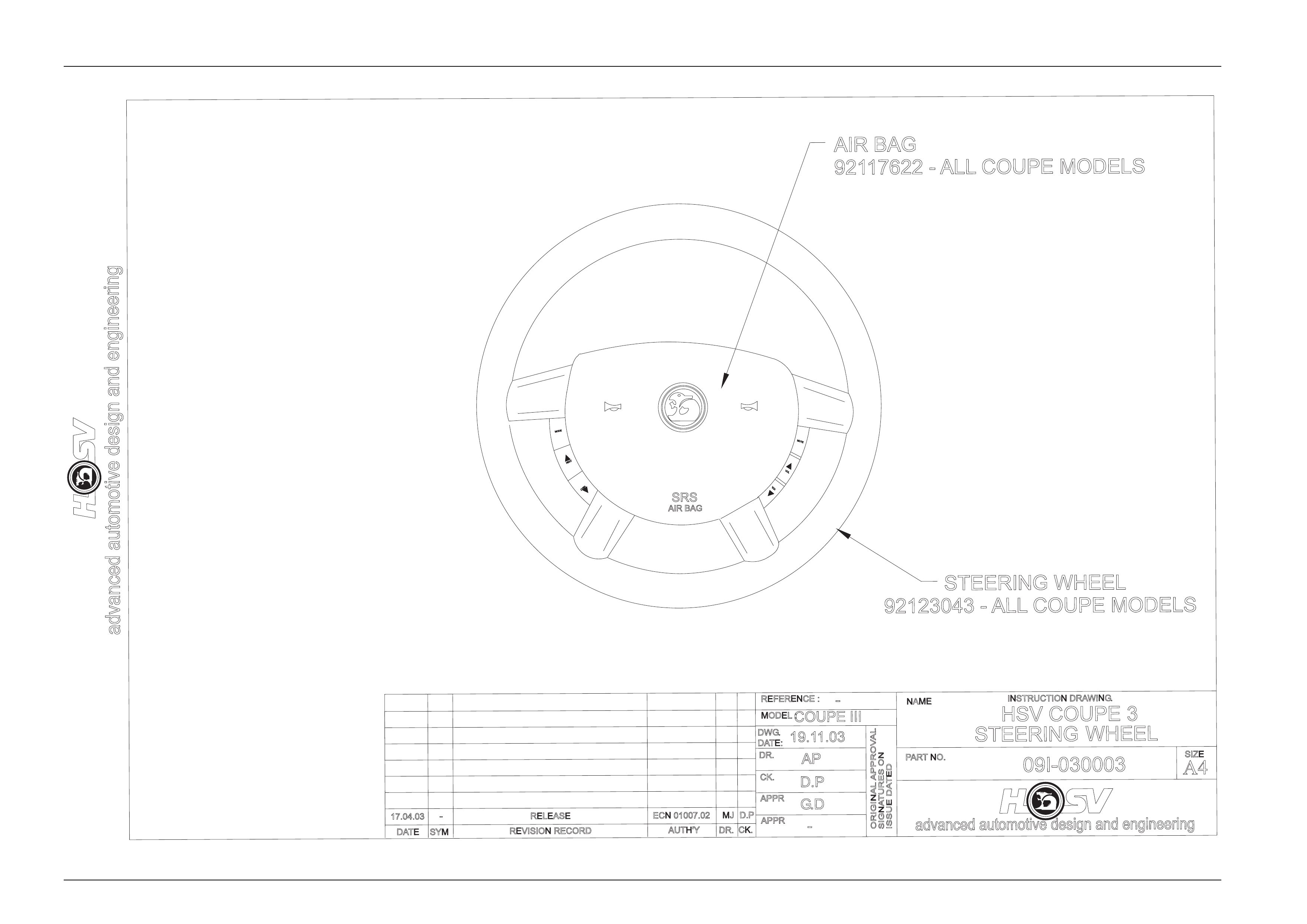
2 Steering Wheel
The steering wheel assembly fitted to all HSV Coupe Serie s 3 models incorporates an HSV design central horn pad
complete with HSV logo, refer to drawing on the following page.
The central horn pad also incorporates the driver’s side air bag.
All other components, fixtures and fasteners are identical to standard Holden parts and, therefore, any service operations
on the assembly should be carr ied out in accordance with the relevant Holden Service Information Su pplement, refer to
Section 9A Steering of the Holden V2 Coupe Series 2 Service Information.
Wheels, Tyres And Steering Wheel Page H - 4
Page H - 4
advanced automotive design and engineering
DATE
PARTNO.
NAME
REVISION RECORD
SYM
ORIGINAL APPROVAL
ISSUE DATED
SIGNATURES ON
DR.
AUTH'YCK.
APPR
APPR
-
MODEL :
REFERENCE :
DWG.
CK.
DATE:
DR.
19.11.03
D.P
AP
COUPE III
-
HSV COUPE 3
STEERING WHEEL
09I-030003
advanced automotive design and engineering
INSTRUCTION DRAWING.
A4
SIZE
RELEASE
AIR BAG
92117622 - ALL COUPE MODELS
STEERING WHEEL
92123043 - ALL COUPE MODELS
SRS
AIR BAG
G.D
17.04.03 -ECN 01007.02 MJ D.P
VOL
VOL
MUTE
NEXT
NEXT
MODE
Wheels, Tyres And Steering Wheel Page H - 5
Page H - 5
3 Wheels and Tyres
3.1 General Description
HSV Coupe Series 3 models are fitted with alloy wheels developed specificall y for each HSV application.
Several types and sizes of wheels are manufactured to suit the various a pplications and each wheel is manufactured
from a single piece of alloy casting.
NOTE
Specific wheel nuts are used to attach ‘T’ design
wheels to the vehicle. T hese nuts are fitted with a
plastic dress cap which must be removed prior to
undoing the wheel nuts.
HSV GTO Coupe Series 3 wheels do not have
steel insert, and, therefore, requi re wheel nuts
with a flang ed seat as per the VT, VT2 and VX
wheel nuts, part No. 10B-970304. Do not use
VS wheel nuts on HSV Cou pe wheels.

Wheels, Tyres And Steering Wheel Page H - 6
Page H - 6
3.2 Service Operations
Alloy wheels fitted to all HSV vehicles are to be serviced in accord ance with the procedures detailed in the relevant
Holden Service Information, refer to Section 10 Wheels and Tyres. In addition, particular care sho uld be taken with the
surface finish of alloy wheels. The manufacturer recommends that alloy surfaces be treate d the same as high – gloss
painted surfaces to prevent corrosion an d general deterior ation.
COUPE 3 WHEEL OPTION CHART
WHEEL PART NUMBER
MODEL 10B-021201 10B-000701SS 10B-020701 10B-020804
GTO COUPE S O
GTO ‘LE’ COUPE O S
GTS COUPE S
‘S’ = Standard ‘O’ = Optional
Wheels, Tyres And Steering Wheel Page H - 7
Page H - 7
Wheels, Tyres And Steering Wheel Page H - 8
Page H - 8
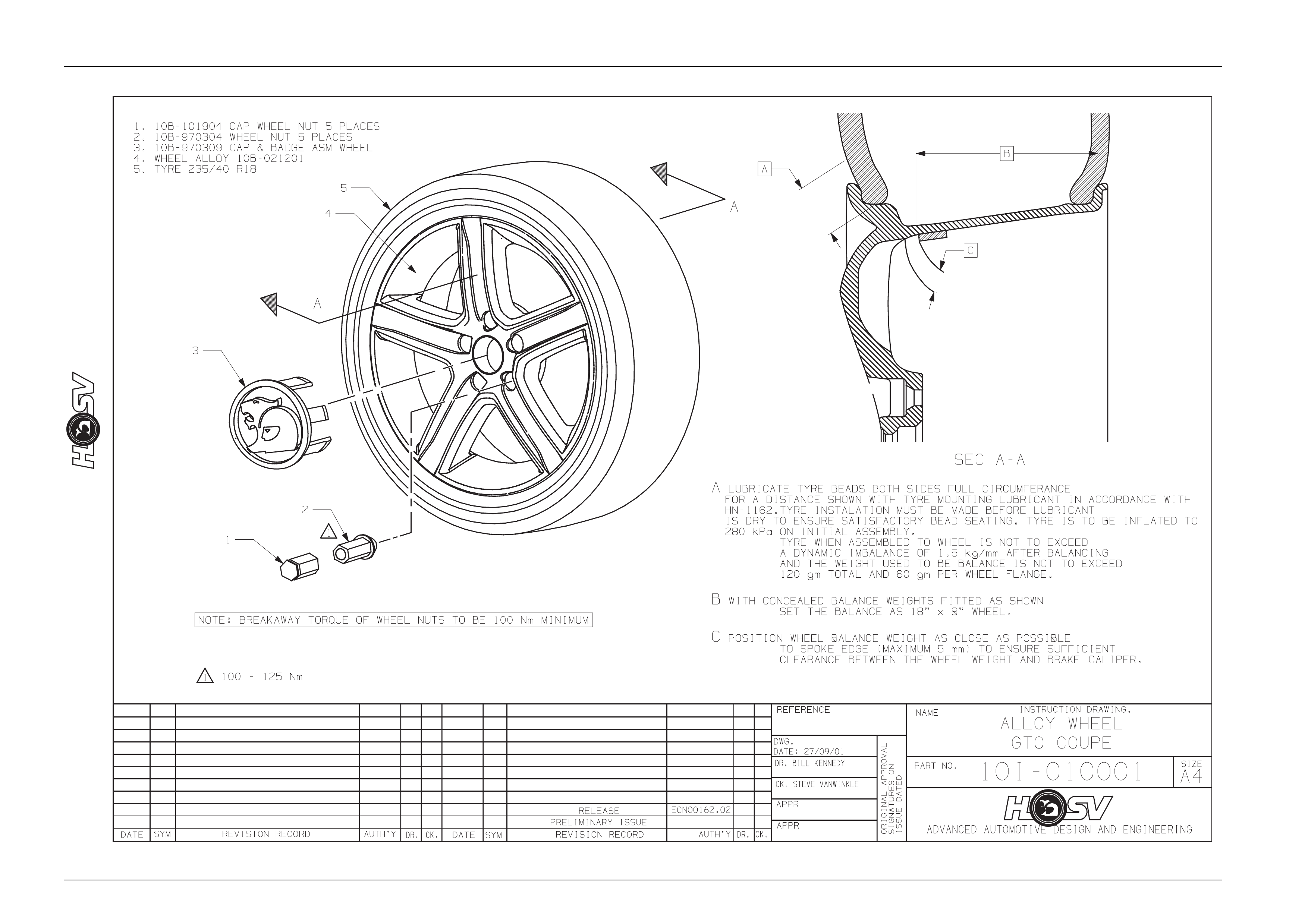
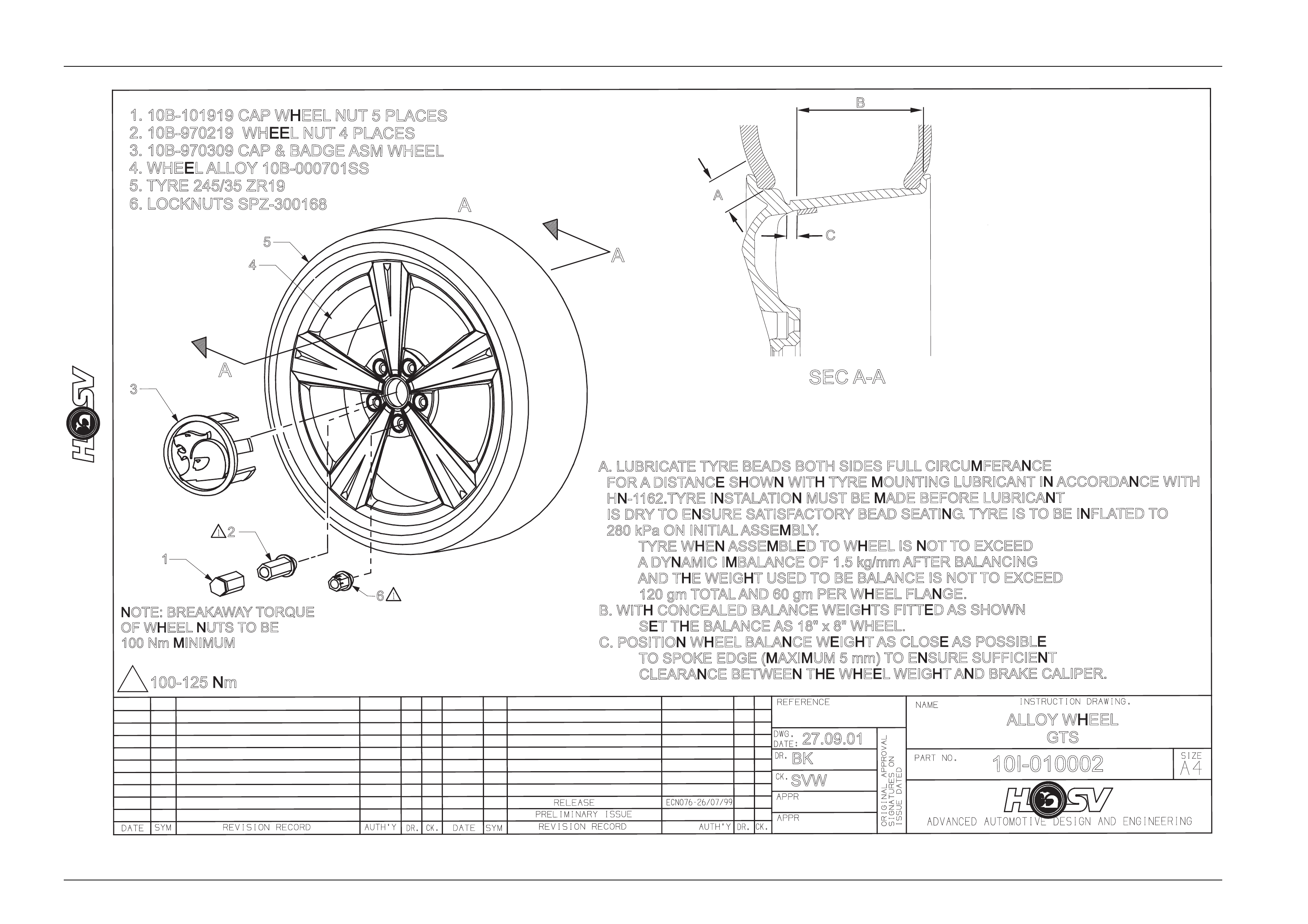
A. LUBRICATE TYRE BEADS BOTH SIDES FULL CIRCUMFERANCE
FOR ADISTANCE SHOWN WITH TYRE MOUNTING LUBRICANT IN ACCORDANCE WITH
HN-1162.TYRE INSTALATION MUST BE MADE BEFORE LUBRICANT
IS DRYTO ENSURE SATISFACTORYBEAD SEATING.TYRE IS TO BE INFLATED TO
280 kPa ON INITIAL ASSEMBLY
.
TYRE WHEN ASSEMBLED TO WHEEL IS NOT TO EXCEED
ADYNAMIC IMBALANCE OF 1.5 kg/mm AFTER BALANCING
AND THE WEIGHT USED TO BE BALANCE IS NOT TO EXCEED
120 gm TOTAL AND 60 gm PER WHEEL FLANGE.
B. WITH CONCEALED BALANCE WEIGHTS FITTED AS SHOWN
SET THE BALANCE AS 18" x 8" WHEEL.
C. POSITION WHEEL BALANCE WEIGHT AS CLOSE AS POSSIBLE
TO SPOKE EDGE (MAXIMUM 5 mm) TO ENSURE SUFFICIENT
CLEARANCE BETWEEN THE WHEEL WEIGHT AND BRAKE CALIPER.
NOTE: BREAKAWAYTORQUE
OF WHEEL NUTS TOBE
100 Nm MINIMUM
100-125 Nm
1
BK
27.09.01
ALLOY WHEEL
GTS
SVW
10I-010002
SECA-A
A
C
B
A
A
4
5
3
2
6
1
1. 10B-101919 CAP WHEEL NUT 5 PLACES
2. 10B-970219 WHEEL NUT 4 PLACES
3. 10B-970309 CAP & BADGE ASM WHEEL
4. WHEEL ALLOY 10B-000701SS
5. TYRE 245/35 ZR19
6. LOCKNUTS SPZ-300168
A
Wheels, Tyres And Steering Wheel Page H - 9
Page H - 9
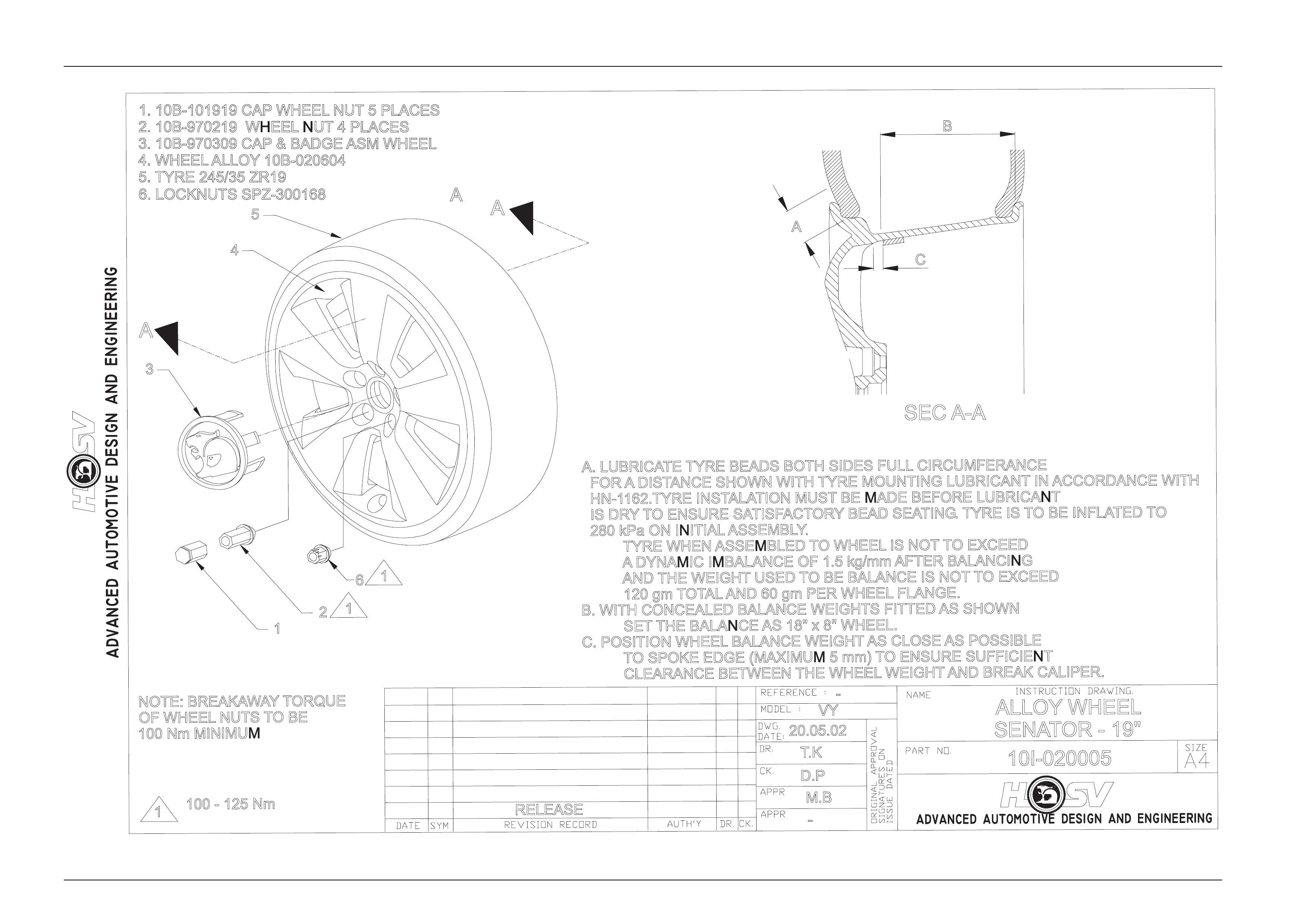
100 - 125 Nm
NOTE: BREAKAWAYTORQUE
OF WHEEL NUTS TOBE
100 Nm MINIMUM
SEC A-A
RELEASE
1M.B
VY
T.K
D.P
20.05.02
10I-020005
-
ALLOY WHEEL
SENATOR - 19"
-
A. LUBRICATE TYRE BEADS BOTH SIDES FULL CIRCUMFERANCE
FOR ADISTANCE SHOWN WITH TYRE MOUNTING LUBRICANT IN ACCORDANCE WITH
HN-1162.TYRE INSTALATION MUST BE MADE BEFORE LUBRICANT
IS DRYTO ENSURE SATISFACTORYBEAD SEATING.TYRE IS TO BE INFLATED TO
280 kPa ON INITIAL ASSEMBLY
.
TYRE WHEN ASSEMBLED TO WHEEL IS NOT TO EXCEED
ADYNAMIC IMBALANCE OF 1.5 kg/mm AFTER BALANCING
AND THE WEIGHT USED TO BE BALANCE IS NOT TO EXCEED
120 gm TOTAL AND 60 gm PER WHEEL FLANGE.
B. WITH CONCEALED BALANCE WEIGHTS FITTED AS SHOWN
SET THE BALANCE AS 18" x 8" WHEEL.
C. POSITION WHEEL BALANCE WEIGHT AS CLOSE AS POSSIBLE
TO SPOKE EDGE (MAXIMUM 5 mm) TO ENSURE SUFFICIENT
CLEARANCE BETWEEN THE WHEEL WEIGHT AND BREAK CALIPER.
2
6
1
1
3
4
5
A
A
B
A
C
1
1. 10B-101919 CAP WHEEL NUT 5 PLACES
2. 10B-970219 WHEEL NUT 4 PLACES
3. 10B-970309 CAP & BADGE ASM WHEEL
4. WHEEL ALLOY 10B-020604
5. TYRE 245/35 ZR19
6. LOCKNUTS SPZ-300168
A