
Electrical And Instruments Page I - 1
Page I - 1
Section I
Electrical And Instruments
ATTENTION
HSV vehicles are equipped with a Supplemental Restraint System (SRS). An SRS consists of seat belt pre-
tensioners (fitted to all front seats), a dri ver’s-side air bag , a passenger’s-sid e air bag and right and left h and
side air bags. Refer to CAUTIONS, Section 12M, of the Holden V2 Series Coupe Service Information before
performing any service operation on or around SRS components, the steering mechanism or wiring. Failure
to follow the CAUTIONS could result in personal injury or unnecessa ry SRS system repairs.
1 General Information ...............................................................................................................................2
2 Purpose...................................................................................................................................................3
3 Instrumentation ......................................................................................................................................4
3.1 General Information............................................................................................................................................... 4
3.2 Service Operations................................................................................................................................................ 5
4 Electrical Facilities.................................................................................................................................6
5 Parking Sensors.....................................................................................................................................7
6 L.E.D. Interior Affect Lighting ...............................................................................................................8
7 HSV Embedded Security System........................................................................................................10
7.1 General Information............................................................................................................................................. 10
7.2 Linking the ESS to a new BCM at the Retailer – BCM In Warranty..................................................................11
7.3 Linking the ESS to a new BCM at the Retailer – BCM out of Warranty........................................................... 12
7.4 Key Programming Mode...................................................................................................................................... 13
Programming Extra Keys To The Vehicle.......................................................................................................... 13
Programming All New Key.................................................................................................................................. 13
7.5 Link Enable Procedure........................................................................................................................................ 14
7.6 Service Operations.............................................................................................................................................. 15
7.7 Diagnostic Procedure.......................................................................................................................................... 16
HSV – Embedded Security System (ESS) Check Sheet (VT II / WH / VY / WK / Coupe III)............................. 16
HSV – Embedded Security System (ESS) Diagnostic Procedure (VT.II / WH / VY / WK / Coupe III) ............. 18
8 Electro-Chromatic Mirrors...................................................................................................................20
8.1 General Information............................................................................................................................................. 20
Circuit Details....................................................................................................................................................... 20
9 HSV Fog Lamps....................................................................................................................................21
9.1 General Information............................................................................................................................................. 21
9.2 Service Operation................................................................................................................................................ 22
10 HSV Rear Spoiler..................................................................................................................................23
10.1 Service Operations.............................................................................................................................................. 23
10.2 Centre High Mounted Stop Lamp Installa tion ................................................................................................... 24

Electrical And Instruments Page I - 2
Page I - 2
1 General Information
The electrical system as fitted to the HSV Coupe series 3 models carries over from Holden V2 Coupe series models.
Refer to the relevant information in Section 12 of the Holden Coupe 2 series Service Information

Electrical And Instruments Page I - 3
Page I - 3
2 Purpose
The purpose of this supplement is to provide information on the HSV electrical and instrument accessories fitted to the
HSV Coupe Series III model. The information is designed to supplement that given in the Holden V2 Coupe Service
Information and details are given where differences occur between the HSV models, an d standard Holden models. A
series of instruction drawings describe the desig n cha nges and indicate specific part numbers, fitting instructions and
relevant notes for vehicle serv icing.
NOTE
If specific technical data on a HSV model is not
contained in this supplement, obtain data for that
model from the Holden V2 Coupe Service
Information Supplement. References are made
throughout this section to Holden Service
Information, to assist in providing information for
specific service operations.
When hoisting (or jacking) HSV models,
ensure that the lifting h ead o f th e hoist lifts on
the chassis before the arm of the hoist
contacts the side-skirt

Electrical And Instruments Page I - 4
Page I - 4
3 Instrumentation
3.1 General Information
A special Instrument Cluster designed by HSV is fitted to all HSV Coupe models. The cluster includes a HSV spee dometer
with an operating range e xtending to 260 km/h. The cluster incorporates a white & black face, red needles, 3 MFD disp lays
and warning lights and, when illuminated, green numerals and letters.

Electrical And Instruments Page I - 5
Page I - 5
3.2 Service Operations
The HSV Coupe instrument cluster and the standard Holden Coupe cluster use the same mounting fixtures and
fasteners. Remove, service and refit the HSV instrument cluster in accordance with the procedures detailed in the
Holden Coupe V2 Service Information.

Electrical And Instruments Page I - 6
Page I - 6
4 Electrical Facilities
The various special HSV options fitted to the Coupe vehicles often require that special or additional electric harness es be
installed. Some of these HSV harnesses are fitted during vehicle build-up at the Holden factor y and other smaller harnesses
(often called ‘a patch harness’) are fitted at the HSV facility when the electrical o ption is being installed. A summary of these
electrical harnesses is included to facilitate service, repair and retro-fitment of the HSV options.
PART No DESCRIPTION
12L-020601 ESS (Embedded Security System)
92118525 HSV L1/L2/L3 Sedan/L3 C ou pe Main Wiring Harness (without T elematics)
92118518 HSV L1/L2/L3 Sedan/L3 C ou pe Main Wiring Harness (with Telematics)


Electrical And Instruments Page I - 8
Page I - 8
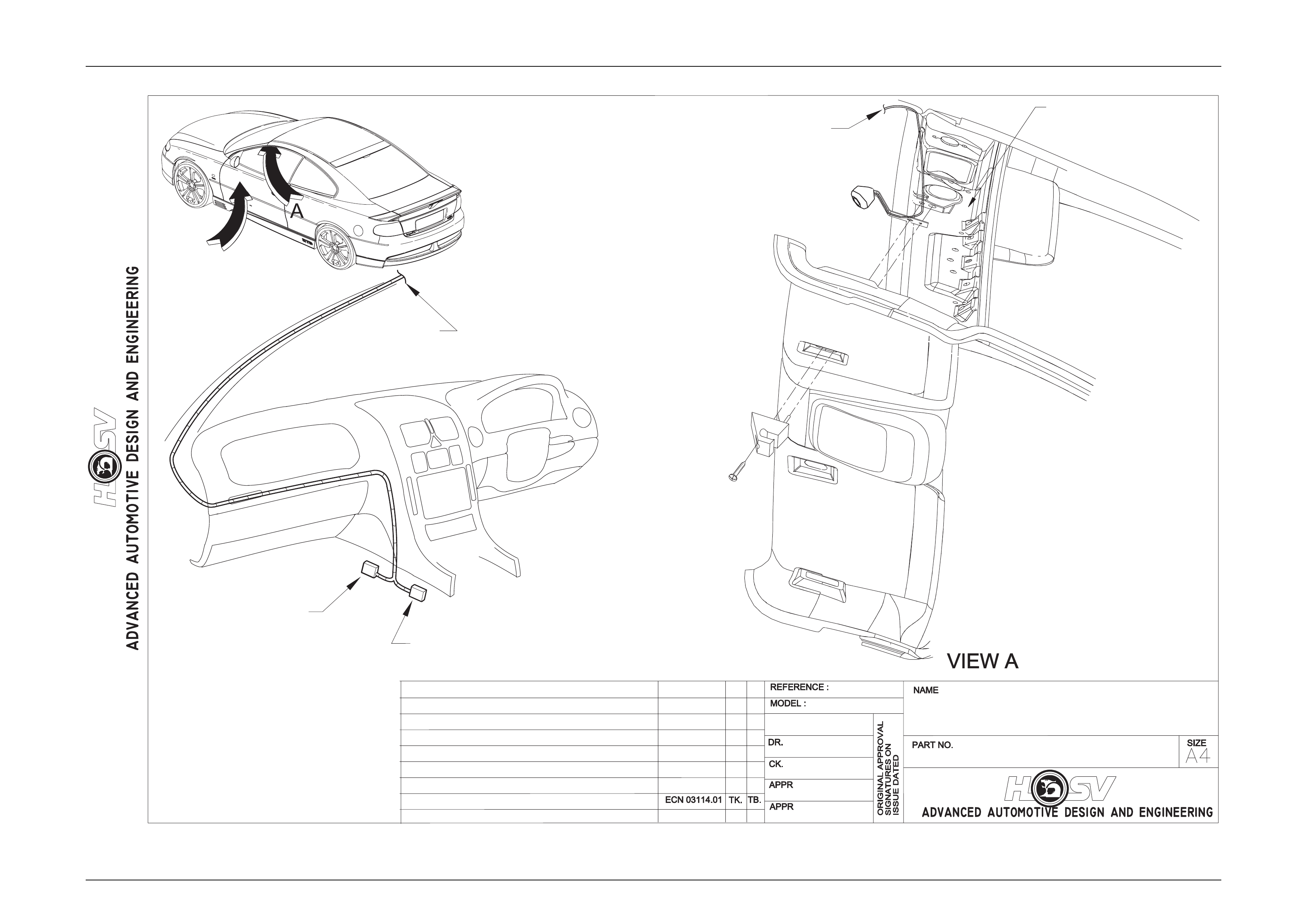
6 L.E.D. Interior Affect Lighting
All HSV Coupe Series III are fitted with L.E.D. Interior Affect Lighting.
The L.E.D. is housed in a small plastic bezel that is heat staked to a brac ket. The bracket is mounted bet ween the
left hand sun-visor hook and t he sheet metal of the vehicle.
The L.E.D. should turn on when the vehicle is un locked using the remote ke y FOB and extinguish 10 seconds after
the car is locked.
The L.E.D. is an effect light that is suppos ed to give a dim wash of light across the centre console and left side of the
dashboard. It is NOT a reading or courtesy lamp.
The L.E.D. is not a serviceab le item and should be replaced if damaged. An electrical represe ntation is given under
the drawing labelled LED-0311
Electrical And Instruments Page I - 9
Page I - 9
REVISION RECORDREVISION RECORD
INSTRUCTION DRAWING.INSTRUCTION DRAWING.
-
AUTH'YAUTH'Y CK.
DR.
-
AP
T. B
04.02.04
DWG.
DATE:
LED-0311
-
LED
ASSEMBLY DWG
INITIAL RELEASEINITIAL RELEASE
ROOF
HEADLINING
WINDSHIELD
RAIL -
WINDSHIELD
HEADER
ROOF
ACCESORY
CONNECTOR
TO L.E.D.
VIEW B
COUPE III
TO “A” PILLAR
(L.H.S.)
B
CONNECTS TO TELEPHONE
ACCESORY CONNECTOR

Electrical And Instruments Page I - 10
Page I - 10
7 HSV Embedded Security System
7.1 General Information
The new HSV Embedded Security System (ESS) is fitted as standard equipment to all HSV VTII, WH, VY, WK and Coupe III
model Vehicles. The ESS is a microprocessor-controlled immobiliser, which automatically interrupts essential electrical
circuits when in “armed mode”. The ESS stores the BCM’s securit y cod e a nd when the car is started it reads this code from
the SCI bus. If this code is different from the stored one the ESS enters armed mode and prevents the vehicle from starting.

Electrical And Instruments Page I - 11
Page I - 11
7.2 Linking the ESS to a new BCM at the
Retailer – BCM In Warranty
If the BCM requires replacement within the BCM warranty period, the Retailer shall be s upplied with a replacement BCM
programmed with the same BCM securit y code as the original BCM. In this case, the replacement BCM and new keys are
simply fitted to the vehicle. No ESS specific requirements are needed.

Electrical And Instruments Page I - 12
Page I - 12
7.3 Linking the ESS to a new BCM at the
Retailer – BCM out of Warranty
When a BCM requires replac ement outside the BCM warranty period the Retailer shall need to obtain a replac ement BCM
and keys from Holden’s Servi ce Parts Operation (HSPO). The replacement BCM and Keys will not contain the same BCM
Security Code as the original BCM.
When a new BCM with different BCM security code is fitted to the vehicle, the Retailer will have to do the following:
- Program a new key to the BCM.
- Link the BCM and PCM.
TECH 2 must be connected to the vehicle diagnostic connector whilst the key is being pr ogrammed and/or ESS is being
linked to the vehicle. The Link Enable Procedure is required to be performed twice to allow an all ne w key to be programmed
and also allow the ESS learn to learn the BCM security code. The procedu r e for programming a new key to a new BCM and
linking the ESS to the vehicle is as follows:
1. Fit new BCM to the vehicle.
2. Ensure all doors, boot and bonnet ar e close d, all doors are unlock ed, dome lamp is in the ‘doors ’ pos ition and the ra dio,
headlight and wash-wipe switches are off.
3. Place new key into the ignition barrel.
4. Turn ignition on. Verify ESS beeps 5 times.
5. For VT.II / VX Vehicles TECH 2 must be operating in the “Normal Mode” submenu of the Body Control Module sub-
menu.
For VY / WK / Coupe III Vehicles TECH 2 must be operating in the Body Control Module sub-menu only.
6. Perform the Link Enable Procedure (see S ection 7.5). Wait 1 second bet ween each lock unlock to e nsure the door lo ck
actuators function correctly during this procedure.
7. Verify that the ESS beeps twice. TECH 2 reports ignition is at 12V DC. The ESS has now entered “Key Programming
mode”.
8. Select Key Programming function – “All New Key” - from the securit y sub-menu in the bo dy menu of the TECH 2. Enter
BCM security code as requested by TECH 2. Complete key programming as requested b y T E CH 2.
9. Turn ignition off and wait for 2 seconds. Turn ignition on.
10. Verify ESS beeps 5 times. (At this stage the ESS is in “armed mode”).
11. For VT.II / VX Vehicles TECH 2 must be operating in the “Normal Mode” submenu of the Body Control Module sub-
menu.
For VY / WK / Coupe III Vehicles TECH 2 must be operating in the Body Control Module sub-menu only.
12. Perform the Link Enable Procedure (see Section 7.5). Wait 1 second bet ween each lock unlock to ensure the door lock
actuators function correctly during this procedure.
13. Verify that the ESS beeps twice. TECH 2 reports ignition is at 12V DC.
14. Link the PCM to the BCM using TECH 2. ESS beeps twice (ESS has now learned the BCM security code).
15. Turn ignition off. Wait until TECH 2 program m ing is complete.
16. Turn ignition on.
17. Turn ignition off. Wait 2 seconds.
18. Turn ignition on.
19. Verify ESS beeps once. The ESS is now operating in “normal mode”.
Crank engine. Verify vehic le starts as normal.

Electrical And Instruments Page I - 13
Page I - 13
7.4 Key Programming Mode
Once the ESS has been placed into key programming mode the ESS will behave as if in “sleep mode” for one ig nition cycle
only. This allows for the one ignition cycle that is required to program a new key to a new or existing BCM. The ESS will
enter “normal mode” for the next ignition c ycle. If the BCM is a new BCM in the vehicle with a new security code, the ESS
will then enter “armed mode” as expected.
Programming Extra Keys To The Vehicle
Programming more keys for the vehicle can be achieved using TECH 2 once the ESS has been re-linked to the vehicle as
described as follows:
1. Ensure all doors, boot and bonnet ar e close d, all doors are unlock ed, dome lamp is in the ‘doors ’ pos ition and the ra dio,
headlight and wash-wipe switches are off.
2. Place new key into the ignition barrel.
3. Turn ignition on. Verify ESS beeps 5 times.
4. For VT.II / VX Vehicles TECH 2 must be operating in the “Normal Mode” submenu of the Body Control Module sub-
menu.
For VY / WK / Coupe III Vehicles TECH 2 must be operating in the Body Control Module sub-menu only.
5. Perform the Link Enable Procedure (see S ection 7.5). Wait 1 second bet ween each lock unlock to e nsure the door lo ck
actuators function correctly during this procedure.
6. Verify that the ESS beeps twice. TECH 2 reports ignition is at 12V DC. The ESS has now entered “Key Programming
mode”.
7. Select Key Programming function – “Extra Key” - from the security sub-menu in the body menu of the TECH 2. When
TECH 2 requests ignition to be c ycled with the existing ke y, leave the new key in the ignition barre l and instead, press
the unlock button on the existing key. Verify the ESS beeps once and the Theft Deterrent LED stops flashing.
Complete key programmin g a s requested by TECH 2.
8. Turn ignition off and wait for 2 seconds.
1. Once and the Theft Deterrent LED stops flashing. Complete key programming as requested b y TECH 2.
2. Turn ignition off and wait for 2 seconds.
3. Turn ignition on. Verify ESS beeps once. The ESS is now operating in “normal mod e”
4. Crank engine. Verify vehic le starts as normal.
9. Turn ignition on. Verify ESS beeps once. The ESS is now operating in “normal mode”.
10. Crank engine. Verif y vehicle starts as normal.
Programming All New Key
Programming an All New Key for the vehicle can be achieved b y performing the following procedure:
1. Ensure all doors, boot and bonnet ar e close d, all doors are unlock ed, dome lamp is in the ‘doors ’ pos ition and the ra dio,
headlight and wash-wipe switches are off.
2. Place new key into the ignition barrel.
3. Turn ignition on. Verify ESS beeps 5 times.
4. For VT.II / VX Vehicles TECH 2 must be operating in the “Normal Mode” submenu of the Body Control Module sub-
menu.
For VY / WK Vehicles TECH 2 must be oper ating in the Body Control Module sub-menu.
5. Perform the Link Enable Procedure (see Section 7.5). Wait 1 second bet ween each lock unlock to e nsure the door lo ck
actuators function correctly during this procedure.
6. Verify that the ESS beeps twice. TECH 2 reports ignition is at 12V DC. The ESS has now entered “Key Programming
mode”.
7. Select Key Programming function – “All New Key” - from the securit y sub-menu in the bo dy menu of the TECH 2. Enter
BCM security code as requested by TECH 2. Complete key programming as requested b y T E CH 2.
8. Turn ignition off and wait for 2 seconds.
9. Turn ignition on. Verify ESS beeps once and Theft Deterrent LED is off. The ESS is now operating in “normal mode”.
10. Crank engine. Verif y vehic le starts as normal.

Electrical And Instruments Page I - 14
Page I - 14
7.5 Link Enable Procedure
Each ESS has it’s own unique Link Enable Code (LEC), programmed into each ESS by HSV. This code corresponds to a
unique sequence of 10 veh icle body functions comprising of the following actions:
1. Drivers door. Open then Close
2. Drivers door Snib. Lock then Unlock
3. Wash-Wipe. On then off
Approximately 60,000 link enable codes ar e available.
For the Link Enable Procedure contact Australian Arrow Pty Ltd Customer Service quoting ESS PIN and Vehicle
Identification / Tag Number.
Telephone: (03) 9785 0792
Facsimile: (03) 9775 0954

Electrical And Instruments Page I - 15
Page I - 15
7.6 Service Operations
In the event of a suspected ESS failure the following check sheet must be followed.
Australian Arrow Pty Ltd Customer Service
Quoting ESS PIN and Vehicle Identification/Tag Number.
Telephone: (03) 9785 0792
Facsimile: (03) 9775 0954

Electrical And Instruments Page I - 16
Page I - 16
7.7 Diagnostic Procedure
In the event of a suspected ESS failure the following diag nostic procedure must be followed:
HSV – Embedded Security System (ESS) Check Sheet (VT II / WH / VY / WK / Coupe III)
In the event of a suspected ESS failure, fill in the following check she et.
Electrical And Instruments Page I - 17
Page I - 17
Dealer Code: _____________ ISOVIN: ________________________ Vehicle Build Date: ______________
Km’s :___________________ ESS Pin No:_____________________ BCM Part No: ______________ _____________ BCM Barcode No: _________________________
This check sheet must signed by the Service Man ag er. _____________________ ____________ ___ Date: __________________
Fax the completed copy to Australian Arrow Customer Service. Facsimile: (03) 9775 0954.
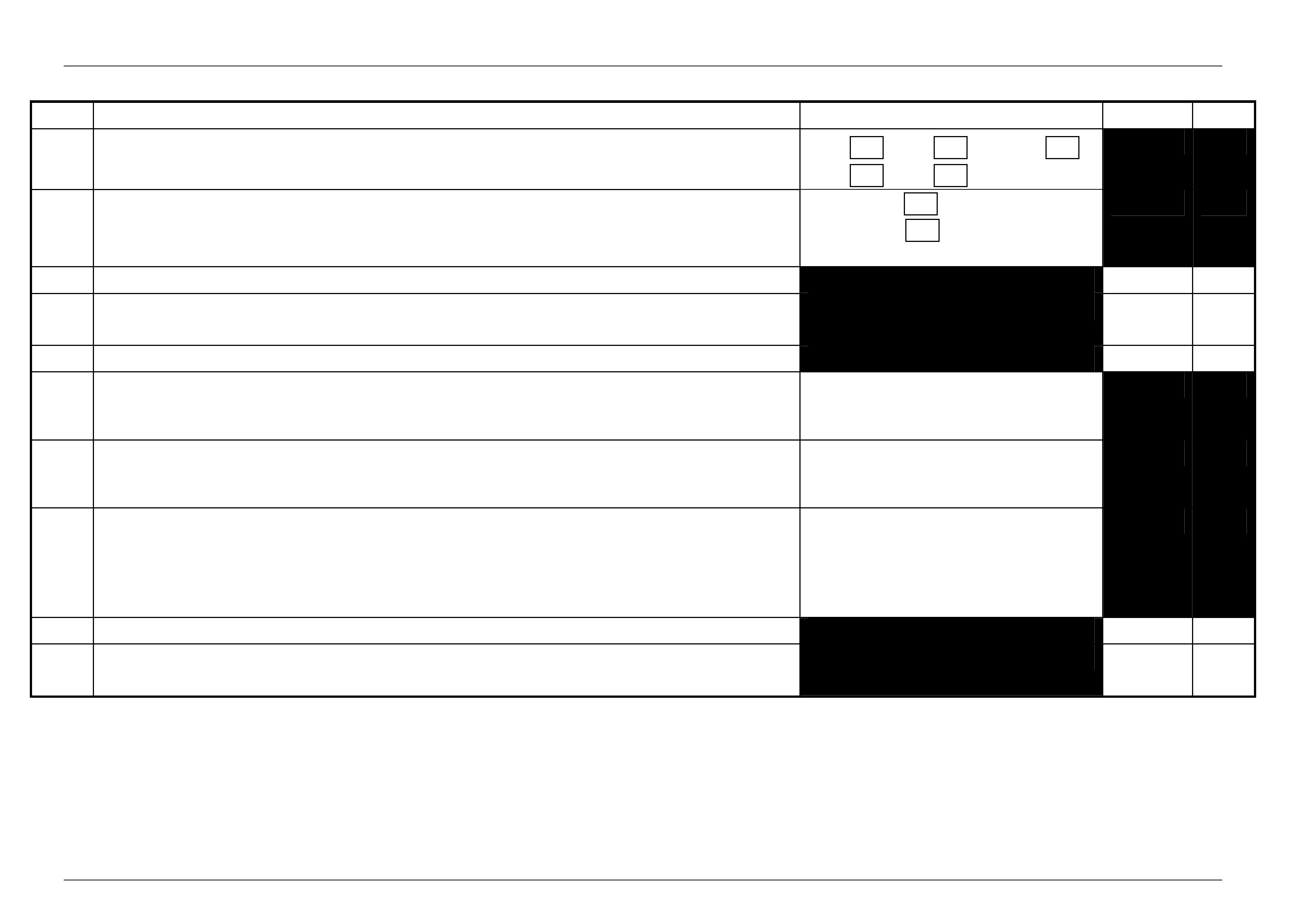
STEP ACTION MEASURED VALUE YES NO
What type of vehicle has the suspected ESS failure? VT.II : VY : Coupe III
WH : WK :
1 Turn ignition to ON position and listen for the number of be eps. Zero beeps:
One beep:
Five beeps: Other:______
2 With the ignition in the ON position, is the Theft Deterrent L ed flashing?
3 Turn Ignition switch to the Start position.
Does the vehicle start?
4 Has there been a BCM replacement?
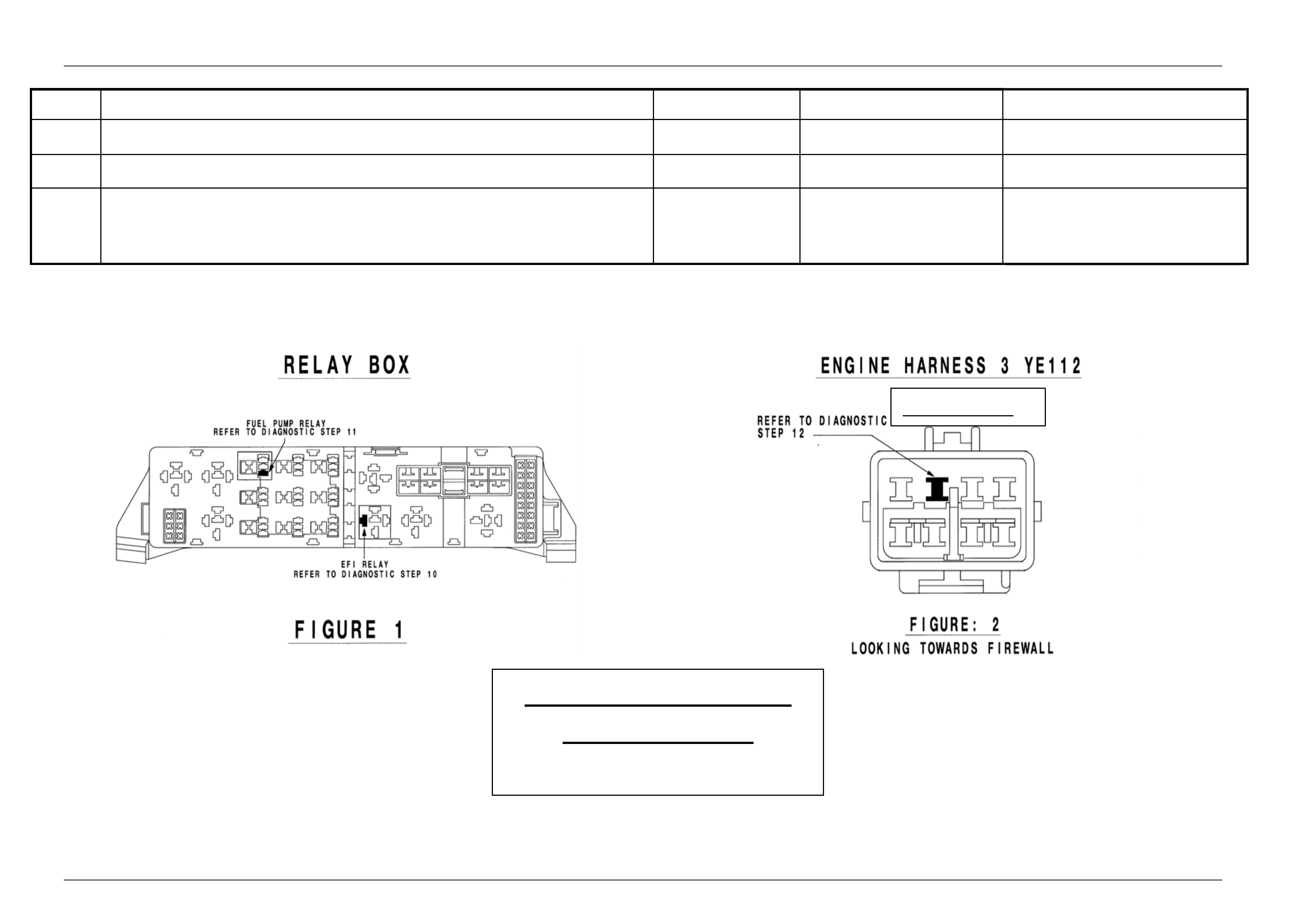
5 Remove the EFI relay and back probe terminal 85 (as per figure 1 for VT.II / WH Vehicles or as per figure 3 for
VY / WK Vehicles), with reference to Ground.
With the Ignition switch to ON, measure DC voltage.
____________ _ volts DC.
6 Remove Fuel Pump rela y and back probe terminal 1 (as per figure 1 for VT.II / WH Vehicles) or terminal.2 (as
per figure 3 for VY / WK Vehicles), to measure continuity with ref. to Ground.
Turn the ignition to ON, measure resistance.
____________ _ Ohms.
7 For VY / WK Vehicles Disconnect Engine C onnector (X206 located abov e passenger kick panel) and back
probe pin 9 (as per figure 4) with reference to ground.
For VT.II / WH Vehicles Disco nnect Engine Connector (YE112) and back probe pin (as per figure 2), with
reference to Ground.
Turn the ignition to ON, measure DC voltage.
____________ _ volts DC
8 Is communications with Tech 2 active?
9 With TDL flashing, operate “Unlock” button on the Remote Control.
Does the TDL stop flashing?

Electrical And Instruments Page I - 18
Page I - 18
HSV – Embedded Security System (ESS) Diagnostic Procedure (VT.II / WH / VY / WK / Coupe III)
STEP ACTION VALUE YES NO
1 • Turn ignition to ON position.
• Is one (1) beep audible?
• Go to Step 2 • Go to Step 3.
2 • Turn Ignition switch to the Start position.
• Does the vehicle start?
• System O.K, return
vehicle to customer. • Go to Step 11.
3 • Are five (5) beeps audible? • Go to Step 13. • Go to Step 8.
4 • Turn Ignition switch to the Start position.
• Does the vehicle start?
• Go to Step 5. • Go to Step 6.
5 • Fill in the ESS check sheet and Contact Australian Arrow Customer Service.
6 • Has there been a BCM replacement? • Go to Step 5. • Go to Step 14.
7 • Perform Serial Data Commun i cations diagnostic as per Holden Ser vice
Manual, then go to Step 5.
8 • Zero beeps were audible? • Go to Step 9. • Record number of beeps,
then go to Step 5.
9 • Turn Ignition switch to the Start position.
• Does the vehicle start?
• Go to Step 5. • Go to Step 10.
10 • Remove the EFI relay and back probe terminal 85 (as per figure.1 for VT.II / WH
vehicle), or (as per figure.3 for VY/WK/CoupeIII vehicle), with reference to
Ground.
• With the Ignition switch to ON, Is the value as specified?
• 12 volts DC. • Go to Step 5. • Refer to Service Manual and
check Ignition system.
11 • Remove Fuel Pump relay and back probe t ermina l.1 (as per figure.1 for VT.II /
WH vehicle), or (as per figure.3 terminal.2 for VY/WK/CoupeIII vehicle), to check
continuity with reference to Ground.
• Turn the ignition to ON. Is the value as specified?
• Less than one
(1) Ohm. • Go to Step 12. • Go to Step 5.
12 • For VT.II / WH vehicle, Disconnect Engine Connector (YE112) and back probe pin
(as per figure 2), with reference to Ground.
• For VY/WK/CoupeIII vehicle, Disconnect Engine Connector (X206 located above
passenger kick panel), and back probe p in.9 (as per figure.4), with reference to
ground.
• Turn the ignition to ON. Is the value as specified?
• 12 volts DC • Go to Step 5. • Go to Step 5.
Electrical And Instruments Page I - 19
Page I - 19
STEP ACTION VALUE YES NO
13 • Is the Theft Deterrent Led flashing? • Go to Step 4. • Go to Step 5.
14 • Is communications with Tech 2 active? • Go to Step 15. • Go to Step 7.
15 • With TDL flashing, operate “Unlock” button on the Remote Key.
• Does the TDL stop flashing?
• Go to Step 5. • Refer to Theft Deterrent
System diagnostics in Ho lden
Service Manual.
(Grey C onn ector)
Australian Arrow Pty. Ltd.
Customer Service.
Telephone: (03) 9785
Electrical And Instruments Page I - 20
Page I - 20
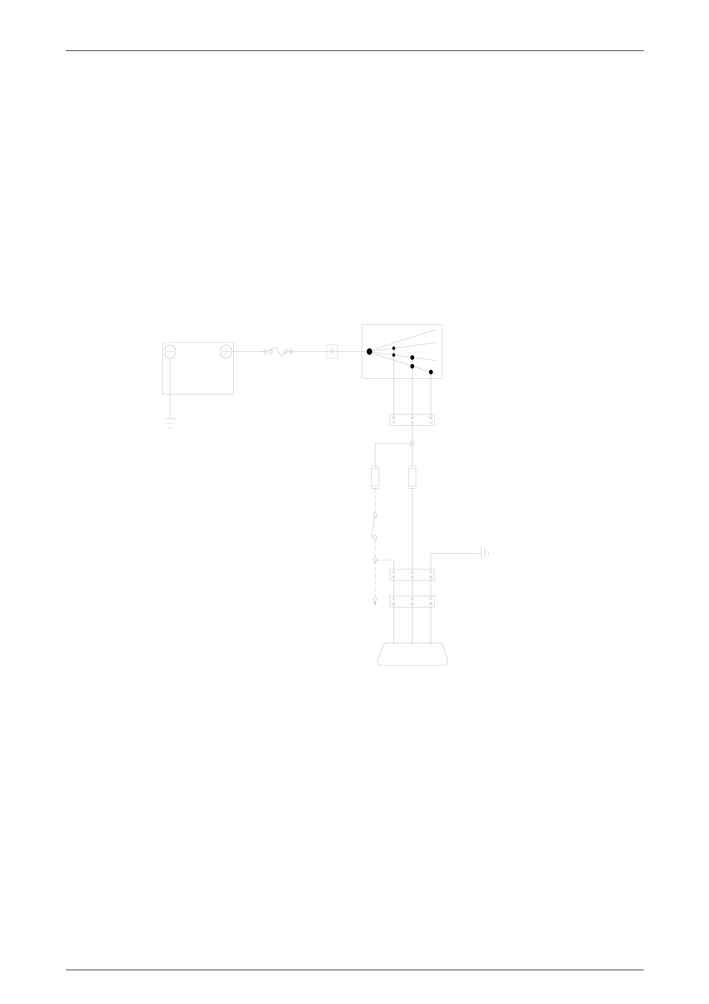
8 Electro-Chromatic Mirrors
8.1 General Information
Electro-chromatic mirrors are standard fitment in GT S and LE Coupe vehicles. The mirror features an electronically
controlled mirror cell which changes colour in response to an applied electrical voltage. This allows automatic darkening
of the mirror during night driving when the headlamps of a following vehicle shine on an integrated light sensor. This
function only operates when the integral sen sor detects low ambient (i.e. at night time). The mirror operates automatically,
however, an AUTO/MANUAL switch provides the driver with the option for the mirror to be darkened during lo w ambient
light conditions regardless of presence or a bsence of following headlamps. When reverse gear is selected, the mirror
automatically lightens.
Circuit Details
FJ RYB44
OFF
ACC
IGN
START
IGNITION SWITCH
YB44
P
F15F12
BACK-UP
SWITCH
YB185
YB113
BR/BLU
LG
P
B/BLU
ELECTRO-CHROMATIC MIRROR
BATTERY

Electrical And Instruments Page I - 21
Page I - 21
9 HSV Fog Lamps
9.1 General Information
HSV Fog lamps are fitted directly to the front fascia of all HSV Coupe III models. The HSV lamps use a glass convex
reflector to provide a wide-angle beam concentrated in a range of 3 0 to 40 metres in front of the lamp. The external lens
incorporates a clear horizontal section.
Fog lamps should be onl y used in adverse weather condition, i.e. fog.
Use of fog lamps on hot sunny da ys may result in failure from overheating.
Fog lamps are not daylight running lights.

Electrical And Instruments Page I - 22
Page I - 22
9.2 Service Operation
Refer to the Holden Coupe V2 Service Information.
12C-031301 LAMP FOG/ LH
12C-031302 LAMP FOG/ RH
NOTE
Condensation may appe ar on the lense of the fog
lamp when:
• Appropriate ambient conditions exist.
• This condensation will clear as the ambient
conditions change or
• After four or five minutes operation of the fog
lamps

Electrical And Instruments Page I - 23
Page I - 23
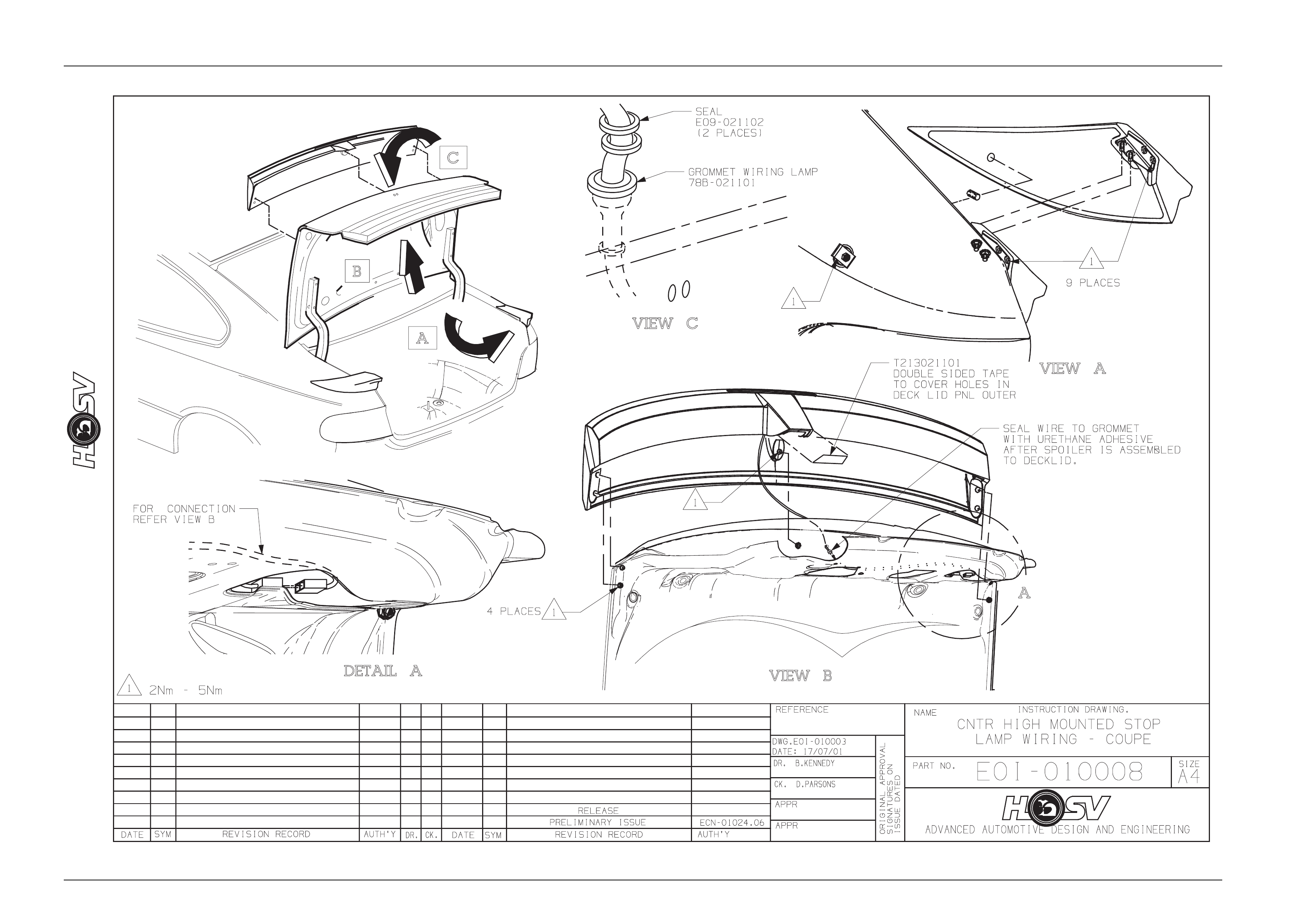
10 HSV Rear Spoiler
The HSV Coupe series 3 models are fitted with Rear Spoiler incorporating Centre High Mounted Stop Lamp (CHMSL).
10.1 Service Operations
To service the HSV Coupe Deck Lid Spoiler mounted stop lamp the following procedure applies:
1. Open deck lid;
2. Disconnect ve hicle’s battery leads;
3. Remove the deck lid inner trim retainers and trim panel;
4. Disengage the Centre High Mounte d Stop Lamp’s harness conn ector from the deck lid harness connector that is
mounted on the right hand side of the deck lid inner panel.
5. Refer to drawing E0I-010008
6. Remove CHMSL wires and terminals from the CHMSL connector and take note of the wire colours and locations in
the connector;
7. Remove the two lamp retaining screws;
8. The lamp wiring passes through a CHMSL gasket and a grommet located in the deck lid outer panel under the
spoiler. The wire is sealed to the grommet with urethan e sealer a nd this seal must be broken to allow the lamp’s
wiring to move, which will allow free play in the wiring so that the lamp can be pulled out of its mounting cavity in
the spoiler and thus giving access to the wiring at the rear of the lamp;
9. Cut the lamp’s wiring leaving a 50mm length of wire protruding from the spoiler, and discard the lamp and the
gasket;
10. Strip 12mm of insulation off the end of the two lamp wires now protruding from the spoiler lamp cavity and tin with
solder.

Electrical And Instruments Page I - 24
Page I - 24
10.2 Centre High Mounted Stop Lamp
Installation
Install the lamp’s gasket to the lamp with the wiring passing through its access hole;
1. Strip 12mm of insul ation off the end of the replacement lamp’s wires and solder join these to the cut original lamp’s
wires protruding from the spoiler. Ensure that an excess of solder is not used, but the joint must be strong as it will
be used to pull the wires from the new lamp through the rear spoiler and deck lid outer panel us ing the original
lamp’s wires;
Carefully pull the wires through the spoiler and deck lid ou ter panel while feeding the new lamp wiring through. Do
not use excessive force if the wiring stops or appears to snag. If this is encountered the spoiler will have to be
removed to reinstall the wiring and lamp assembl y. Refer to E0I-010008. for this information. Ensure that the new
lamp’s Gasket is located bet ween the lamp b ase and the bottom of the spoiler recess, and is not kinked or buckled,
and that the wiring passes throug h the access hole in the gasket;
2. Install the lamp and gasket into the spoiler re cess;
3. When inserting the CHMSL into the recess take care not to damage the wiring and gasket, and fasten the attaching
screws;
4. Once installed cut the CHMSL wires to a length that allo ws the wires to run to the connector located on t he deck lid
inner panel;
5. Strip the insula tion off the wires and attach the new terminals provided, install the terminals into the connector
housing using the wiring colours and locations previously noted in the removal procedure;
6. Assemble the CHMSL co nnector and wiring with the deck lid connector and harness assembly;
7. Reconnect the battery terminals and check the function of the lamp;
8. If the lamp does not function it is possible that the wires have been incorre ctly installed in their locations in the
connector body. Refer to the wiring and colour locations noted prior to the removal procedure;
9. Seal the CHMSL wiring where it passes through the deck lid grommet with urethane sealer.
Ref. Drawing E0I-010008, view B;
10. Install the deck lid inner panel trim and retainers;
11. Clean and polish all areas where work has been conducted.
Electrical And Instruments Page I - 25
Page I - 25