
Body Page B-1
Section B
Body
ATTENTION:
HSV vehicles are equipped with a Supplemental Restraint System (SRS). An SRS consists of seat belt pre-
tensioners (fitted to all front seats), a dri ver’s-side air bag , a passenger’s-sid e air bag and left and right hand
side air bags. Refer to CAUTIONS, Section 12M, of the Holden V2 Coupe Service Information before
performing any service operation on or around SRS components, the steering mechanism or wiring. Failure
to follow the CAUTIONS could result in personal injury or unnecessa ry SRS system repairs.
1 Purpose...................................................................................................................................................3
1.1 General Information............................................................................................................................................... 3
2 Body Ornamentation..............................................................................................................................4
3 Seats........................................................................................................................................................5
3.1 HSV Coupe 4 Seat Assembly Matrix .................................................................................................................... 7
3.2 HSV Trim Cover Assembly Matrix........................................................................................................................ 8
3.3 HSV Pad Matrix ...................................................................................................................................................... 9
3.4 HSV Frame Matrix................................................................................................................................................ 10
4 Body Components ...............................................................................................................................11
4.1 Body Styling......................................................................................................................................................... 11
4.2 Paint Protectors................................................................................................................................................... 13
4.3 Radiator Grille Service Information.................................................................................................................... 16
General ................................................................................................................................................................. 16
Grille Surround Attachment.............................................................................................................................. 16
Grille Mesh....................................................................................................................................................... 16
Grille Badge Mounting Boss and Badge........................................................................................................... 16
4.4 Fog Lamp Surround Service Information .......................................................................................................... 17
General ................................................................................................................................................................. 17
Fog Lamp Surrounds Attachment..................................................................................................................... 17
4.5 Fog Lamp Recess Decal Installation.................................................................................................................. 18
General ................................................................................................................................................................. 18
Fog Lamp Recess Decal Installation................................................................................................................ 18
4.6 Front Fender Liner Service Information............................................................................................................. 25
Removal................................................................................................................................................................ 25
Installation............................................................................................................................................................ 25
4.7 Rear Fender Liner Service Instruction............................................................................................................... 32
Removal................................................................................................................................................................ 32
Installation............................................................................................................................................................ 32
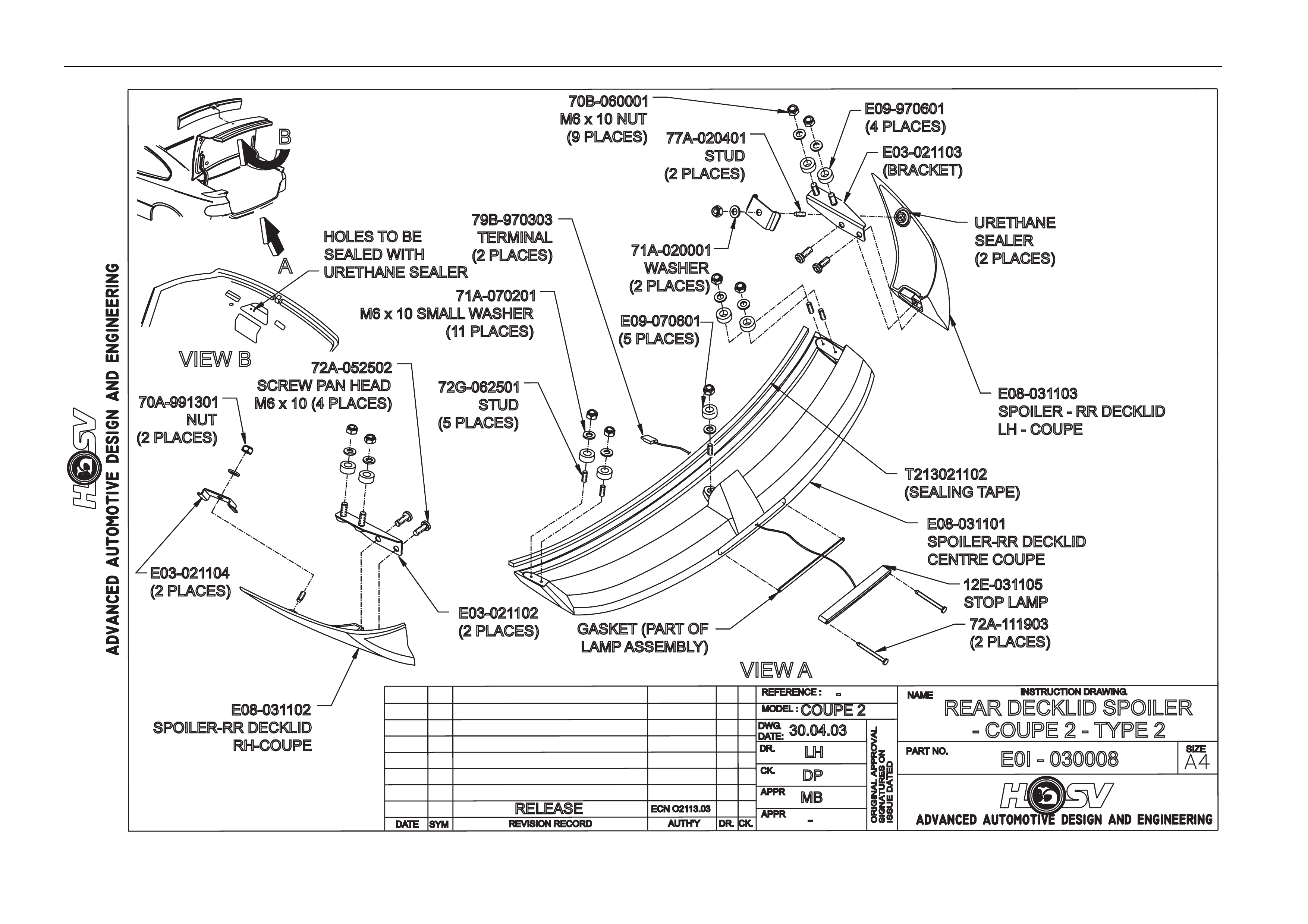
5 Rear Spoiler Type 2..............................................................................................................................42
5.1 Service Operations.............................................................................................................................................. 42
Spoiler Ends......................................................................................................................................................... 42
Removal........................................................................................................................................................... 42
Installation........................................................................................................................................................ 42
Spoiler Centre Section ........................................................................................................................................ 42
Removal........................................................................................................................................................... 42
Installation........................................................................................................................................................ 42

Body Page B-2
5.2 HSV Coupe Rear Spoiler – New Rear Quarter Panel and New Spoiler............................................................ 45
Decklid Centre Spoiler Outer Holes ................................................................................................................... 45
Centre Spoiler Centre Holes ............................................................................................................................... 46
Side Spoiler Upper Attaching Holes................................................................................................................... 46
Side Spoiler Lower Attaching Hole .................................................................................................................... 47
De-burring and Anti-corrosion Treatment ......................................................................................................... 49
Sealing.................................................................................................................................................................. 49
General Precaution.............................................................................................................................................. 49
6 Roof Spoiler..........................................................................................................................................50
6.1 Service Operations.............................................................................................................................................. 50
Removal................................................................................................................................................................ 50
Installation............................................................................................................................................................ 50
7 Plastic Components.............................................................................................................................52
8 Front and Rear Fender Service Instructions.....................................................................................56
8.1 Front Fenders....................................................................................................................................................... 56
Removal................................................................................................................................................................ 56
Installation............................................................................................................................................................ 56
8.2 Rear Fenders........................................................................................................................................................ 57
Removal................................................................................................................................................................ 57
Installation............................................................................................................................................................ 57

Body Page B-3
1 Purpose
The purpose of this section is to provide information on the body and body components fitted to HSV Coupe 4 ve hicles.
The information is designed to supplement the information contained in the Holden V2 Coup e Service Information, and
details are given where differences occur between the HSV models and standard Holden models. A series of instruction
drawings describe the design changes and indicate specific part numbers, fitting instructions and relevant notes for
vehicle servicing.
NOTE
If specific technical data on a HSV model is not
contained in this supplement, obtain data for that
model from the relevant Holden V2 Coupe
Service Information Supplement. References are
made throughout this section to Holden Service
Information, to assist in providing information for
specific service operations.
When hoisting (or jacking) HSV models,
ensure that the lifting h ead o f th e hoist lifts on
the chassis before the arm of the hoist
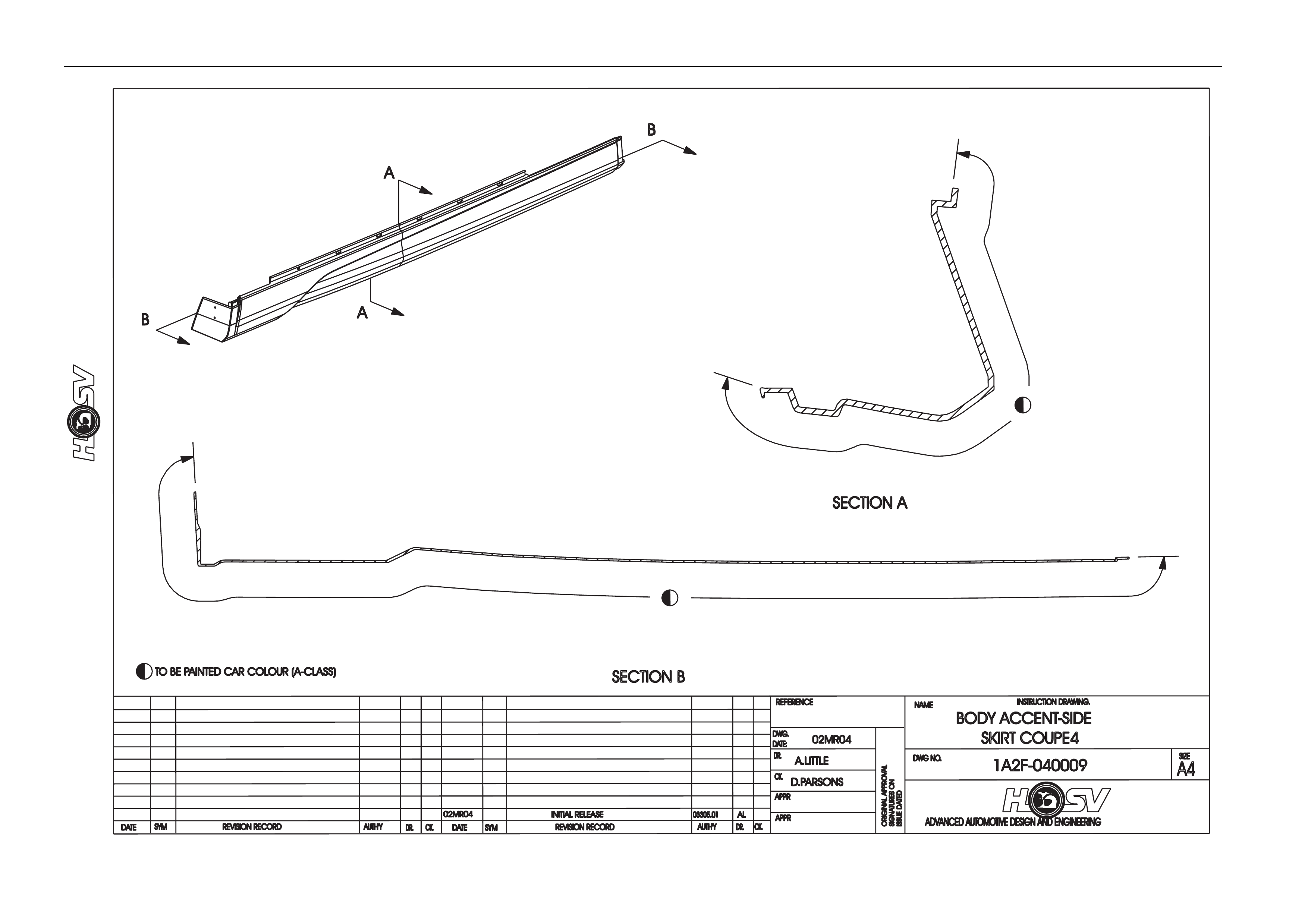
contacts the side-skirt
1.1 General Information
The HSV Coupe 4 is an all ne w model for HSV and therefore body components are not intercha ngeable with previous
models.
HSV Coupe 4 models are equip ped with unique Body Side Skirts , 3-piece Rear Spoiler, Roof Spoiler, Front Bumper Bar
Fascia and Rear Bumper Bar Fascia.
The Coupe 4 model is fitted with a glass panel sunroof as standar d.
For all body dimensions refer to Section 1A2 Body Dimensions of the Holden V2 Coupe Series Models Service
Information.
It is recommended that before any body repa irs are undertaken that the components invol ved be closely inspected to
gain a clear understanding as to their design.
This should include attachi ng methods, assembly margins, painted features and paint accents.
Where practical Digital Photographs taken prior to work commencing could be of assistance to be used at a later date for
reference.

Body Page B-4
2 Body Ornamentation
HSV models are fitted with HSV specific dec als and badges to identify each model and powertrain option.
This exclusive HSV ornamentation is positioned in exact locations on each HSV model.
The ornamentation for each m odel is specified by part number in this section.
Accurate dimensions are also provided to assist with replacement of these parts.

Body Page B-5
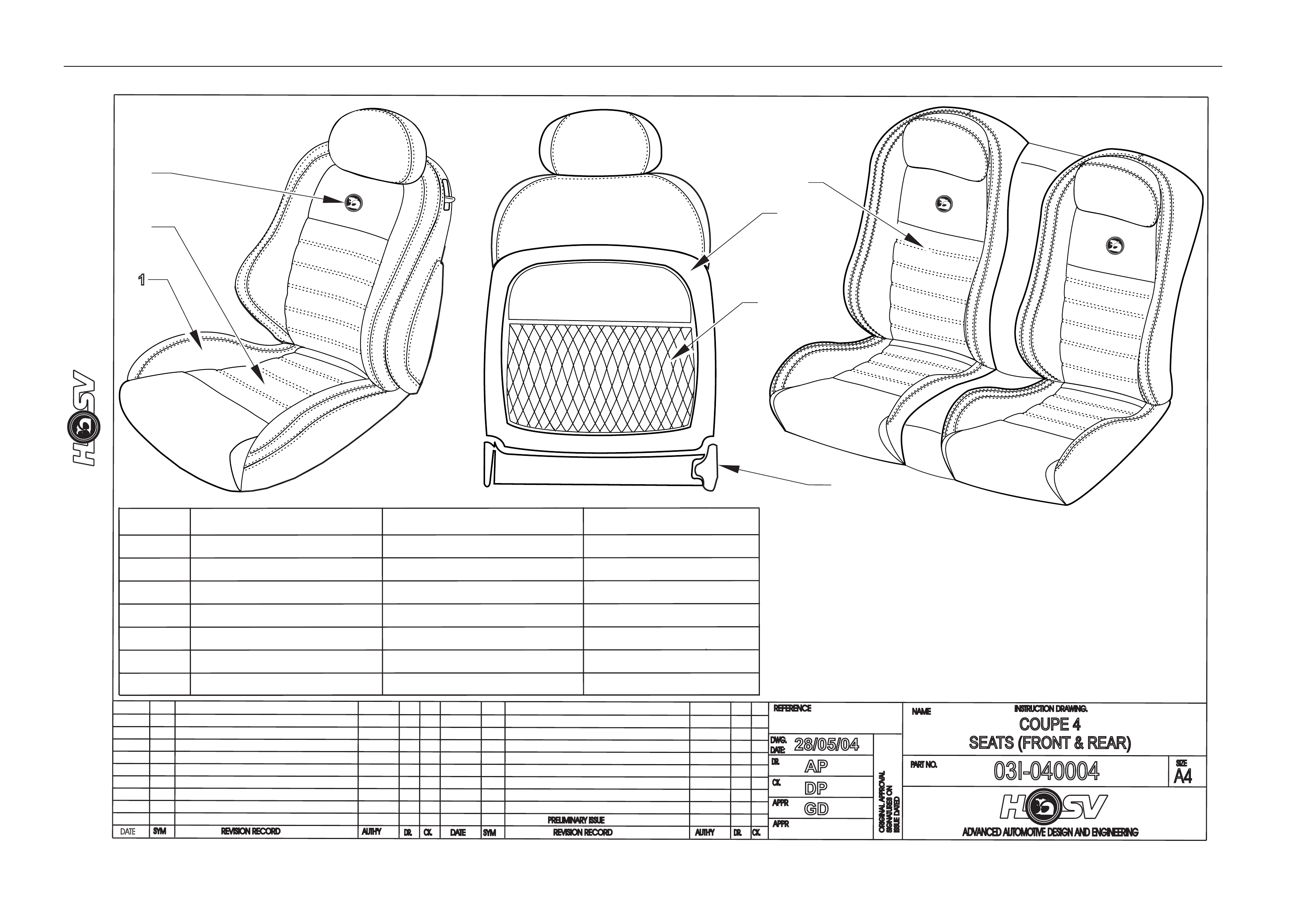
3 Seats
The HSV Coupe 4 is fitted with all new exclusive seat designs.
A full range of replacement parts is available for each specific HSV seat item.
Body Page B-6
DATE
ISSUEDA
TED
AUTH'Y
CK.
SYM
AUTH'Y
REVISION RECORD
DATE
SYM
SIGNATURES ON
ORIGINAL APPROVAL
DR.
ADVANCED AUTOMOTIVE DESIGN AND ENGINEERING
03I-040004
INSTRUCTION DRAWING.
A4
SIZE
COUPE 4
SEATS (FRONT & REAR)
REVISION RECORD
PRELIMINARY ISSUE
CK.
NAME
PART NO.
CK.
REFERENCE
DWG.
DR.
DATE:
APPR
APPR
DR.
28/05/04
AP
DP
GD
BOLSTER LEATHER - MILL PEBBLE
PERFORATED LEATHER
EMBROIDERY
VINYL
COMP PLASTIC
ANTHRACITE
ANTHRACITE
ANTHRACITE
ANTHRACITE
ANTHRACITE
ANTHRACITE
BLACK / OCHRE
/ OCHRE
M20
NET
INSERT
LION / HELMET LOGO
BACK COVER
SEAT PLASTICS
STITCHING THREAD
MAP POCKET
1
1
2
2
3
3
4
4
5
5
6
6
7
7
ITEM PART NAME MATERIAL COLOUR

Body Page B-7
3.1 HSV Coupe 4 Seat Assembly Matrix
Colour
Coupe 4 Seat Kits
Front And Rear Seat Asm.
Front RH Seat Asm.
Front LH Back
Asm. Rear
Cushion
Asm. Rear
Seat
NK (Anthricite)
CR (Ochre)
1 92209618 4101260 Coupe 4
Anthricite
Leather 4101262 4101263 4101264 4101265 X
2 92209619 4101261 Coupe 4
Ochre Leather 4101266 4101267 4101268 4101269 X
NOTE:
J06 & K06 are HSV prefixes for front & rear
components respectively.
HSV Suffixes are one letter only, and are K(NK),
Y(BY), D(ID), V(HV).
E.G. Lear part 4101188BY is HSV K06-
4101188Y, 4101193NK is HSV J06-4101193K

Body Page B-8
3.2 HSV Trim Cover Assembly Matrix
Colour
Coupe 4 Trim Assemblies
Front And Rear
Trim
Asm.
Fsc
Trim
Asm.
Fsb RH
Trim
Asm.
Fsb LH
Trim
Asm. Fs
H/Rest
Trim
Asm
Rsc
Trim
Asm.
Rsb RH
Trim
Asm.
Rsb LH
Trim
Asm.
Rs
H/Rest
NK
(
Anth
r
CR
(
Ochre
1 4101260 COUPE 4
ANTHRICITE
LEATHER 4101270 4101272 4101271 4102100 4101273 4101274 4101275 4102101 X
2 4101261 COUPE 4
OCHRE
LEATHER 4101270 4101272 4101271 4102100 4101273 4101274 4101275 4102101 X
NOTE :
J06 & K06 are HSV prefixes for front & rear
components respectively.
HSV Suffixes are one letter only, and are K(NK),
Y(BY), D(ID), V(HV).
E.G. Lear part 4101188BY is HSV K06-
4101188Y, 4101193NK is HSV J06-4101193K

Body Page B-9
3.3 HSV Pad Matrix
Coupe 4 Pads
Front And Rear Front
Seat
Cushion
Front
Seat
Cushion
Insert
Front
Seat
Back
Front Seat
Headrest Rear
Seat
Cushion
Rear
Seat
Back
Rear
Seat
Headrest
Rear
Seat
Cushion
Insert
Rear
Seat
Back
Insert
1 COUPE 4 4003612 4003610 4005137 4004438 4003176 4003177 4003616 4004035 4004058

Body Page B-10
3.4 HSV Frame Matrix
Coupe 4 Frames
Front And Rear Front Seat
Cushion Front Seat
Back Rh Front Seat
Back Lh Rear Seat
Cushion Rear Seat
Back
1 COUPE 4 4004611 4004968 4004967 4005124 4005123

Body Page B-11
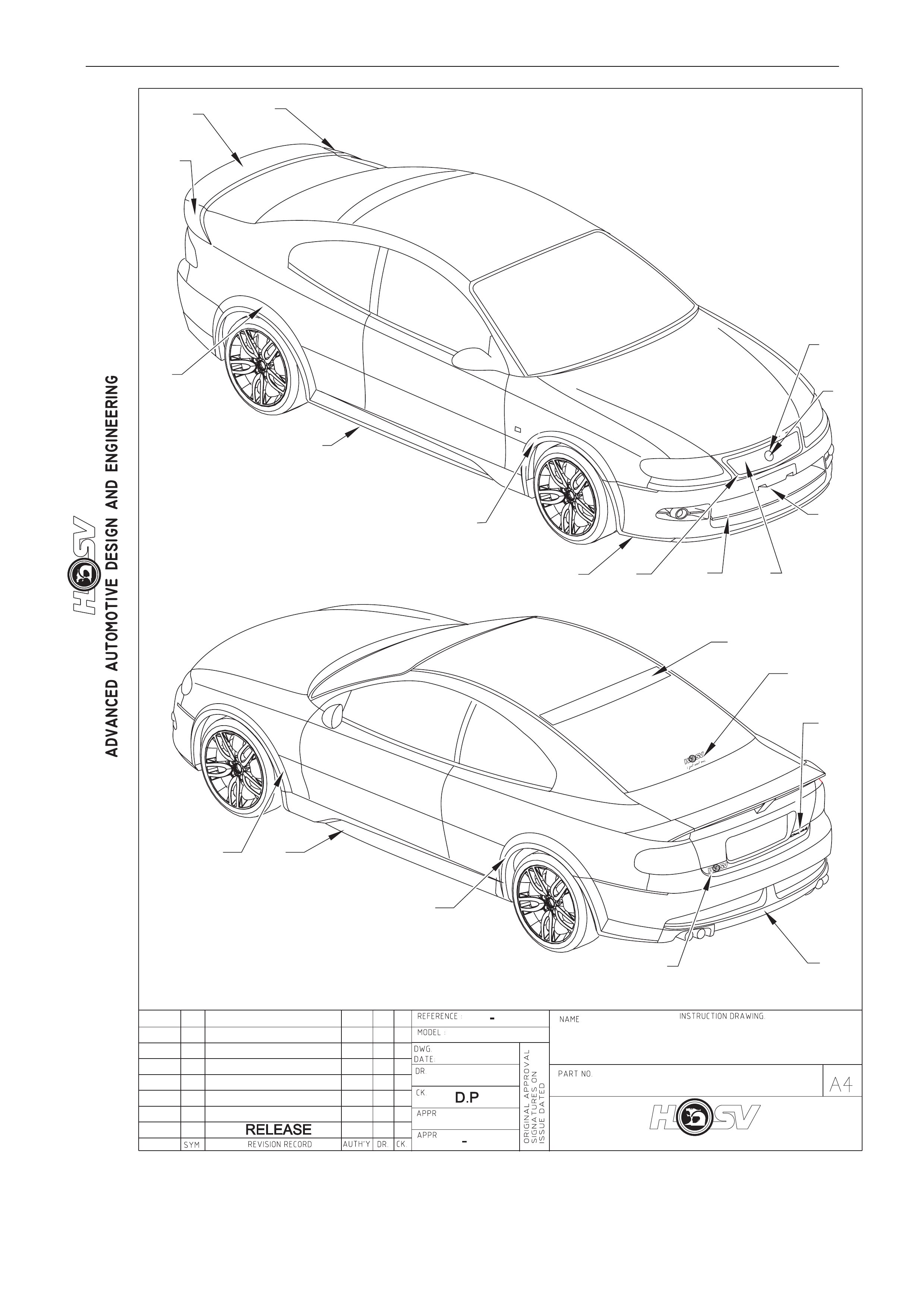
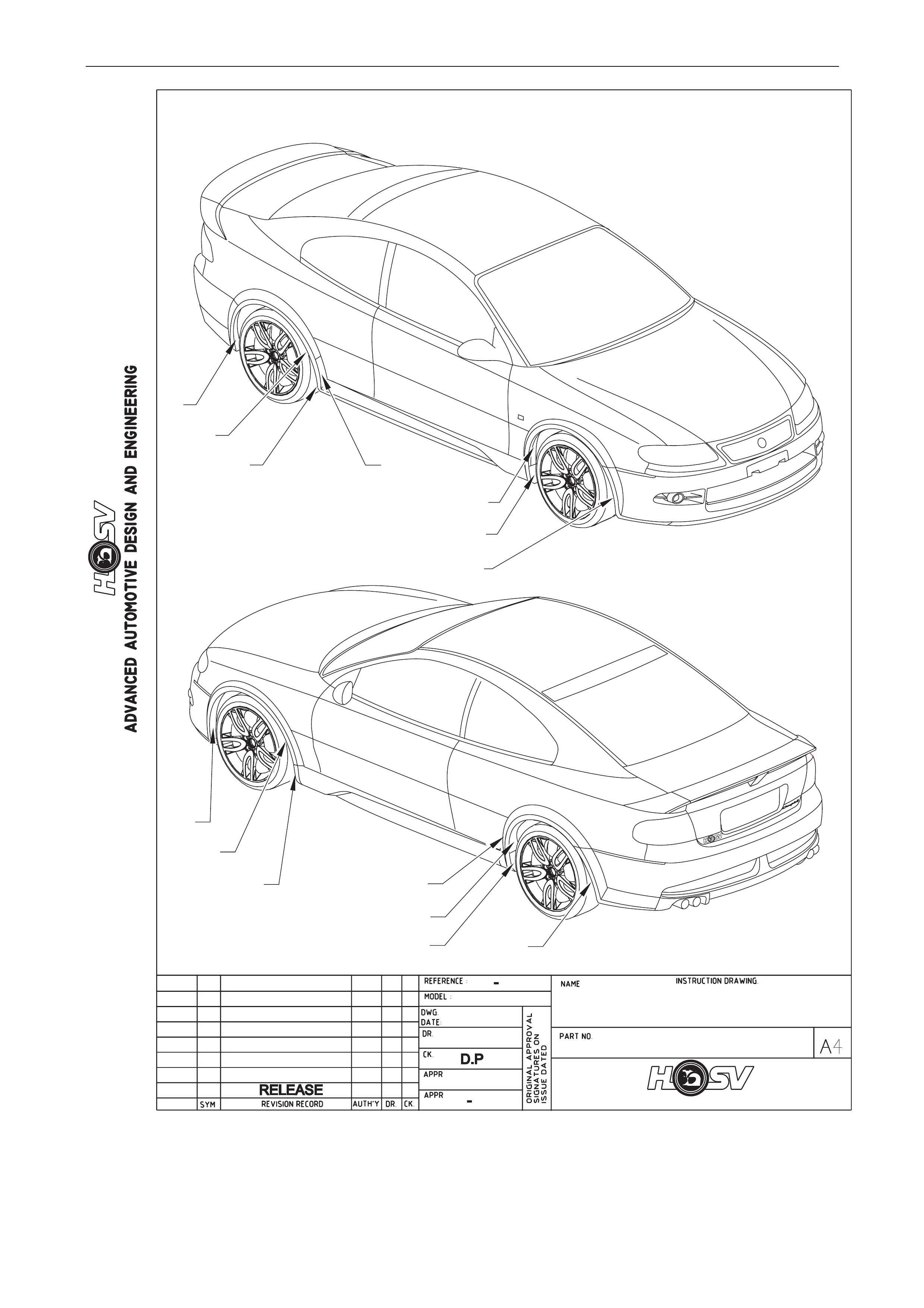
4 Body Components
4.1 Body Styling
CONTENTS OF BODY STYLING PACKAGE
PART No QTY DESCRIPTIONS REF
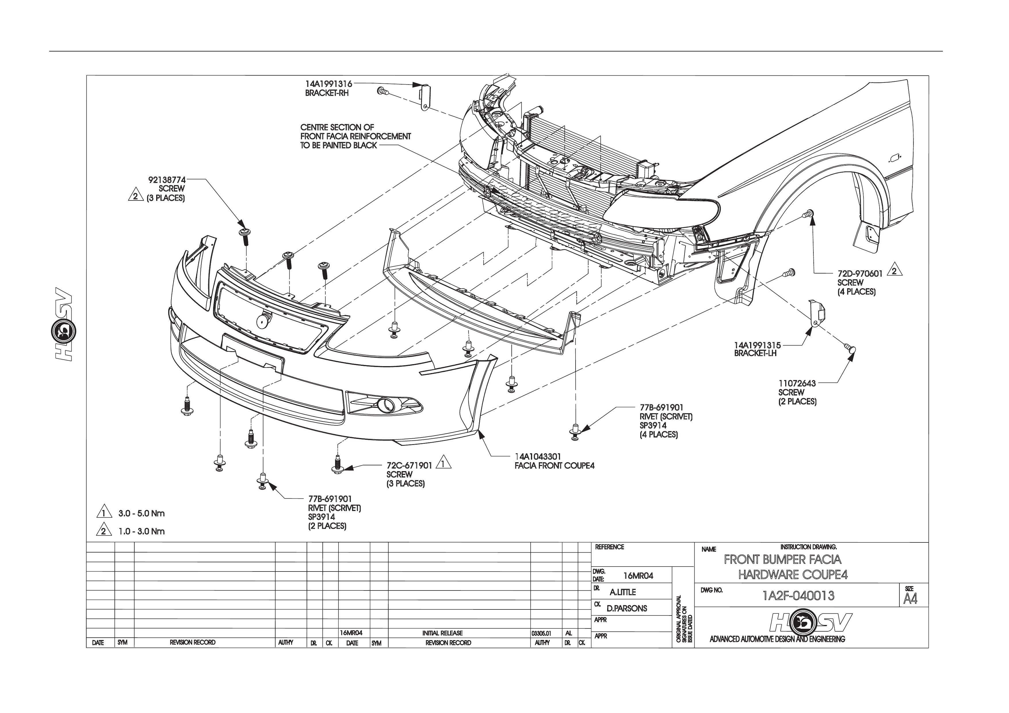
14A1043301P 1 FRONT FACIA 1
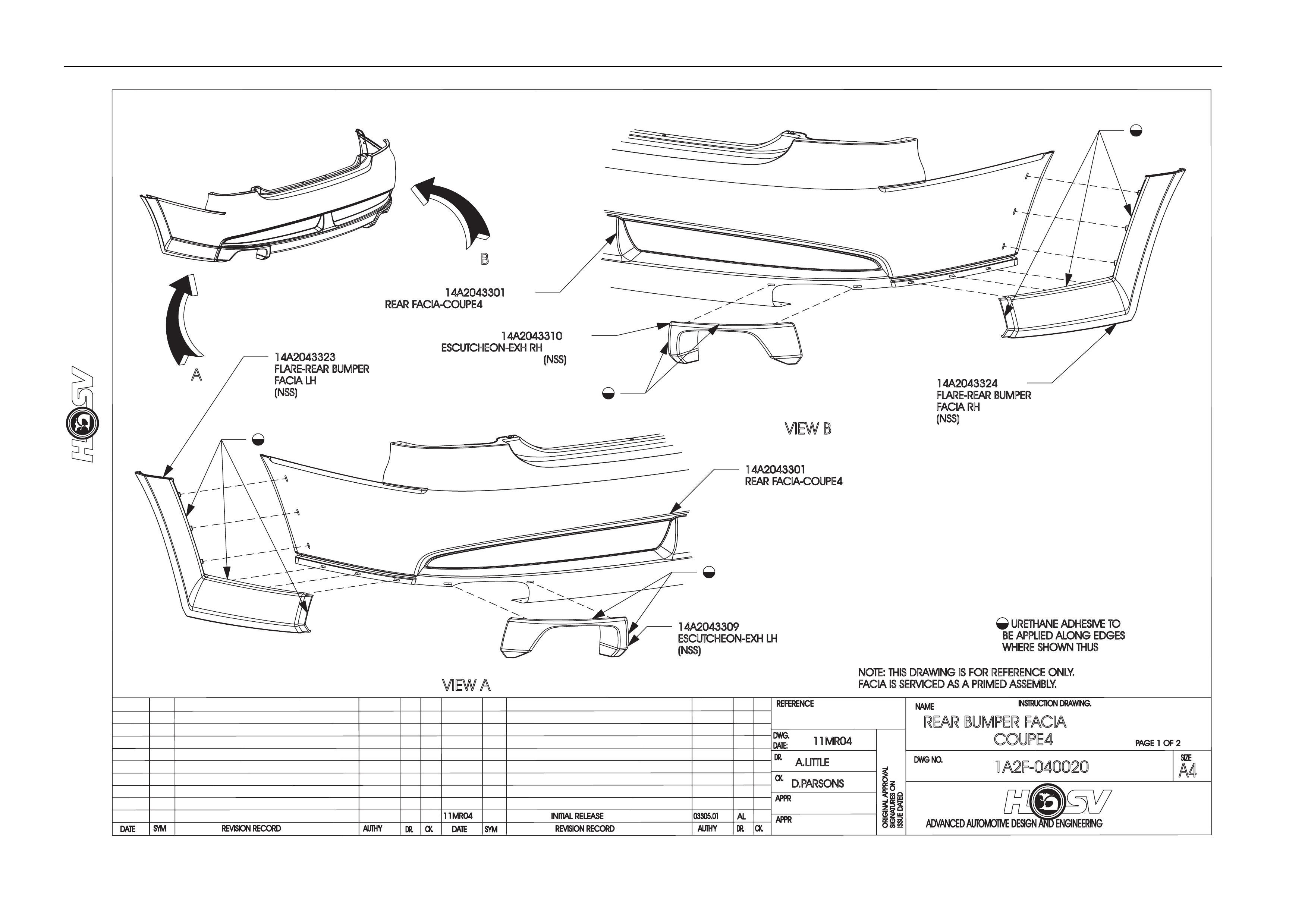
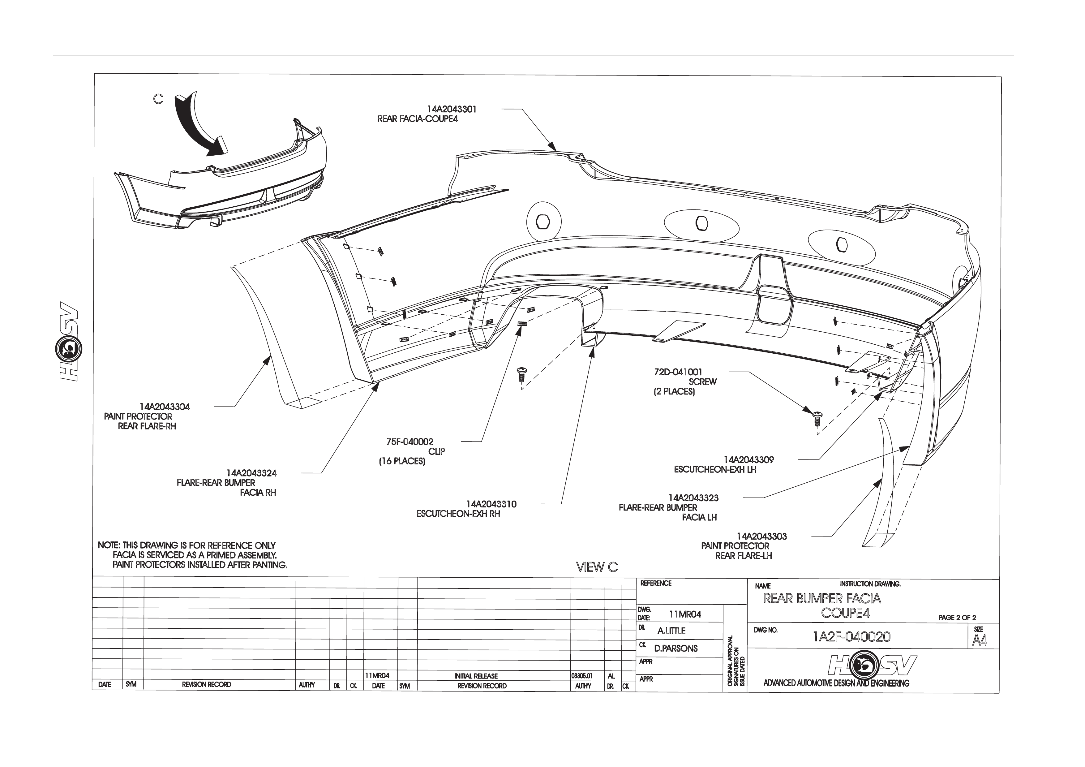
14A2043313P 1 REAR FACIA 2
A08-043316P 1 SIDE SKIRT RH 3
A08-043315P 1 SIDE SKIRT LH 4
H08-020504 1 BADGE LION & HELMUT 63mm 5
13C-043301 1 BEZEL GRILLE UPPER 6
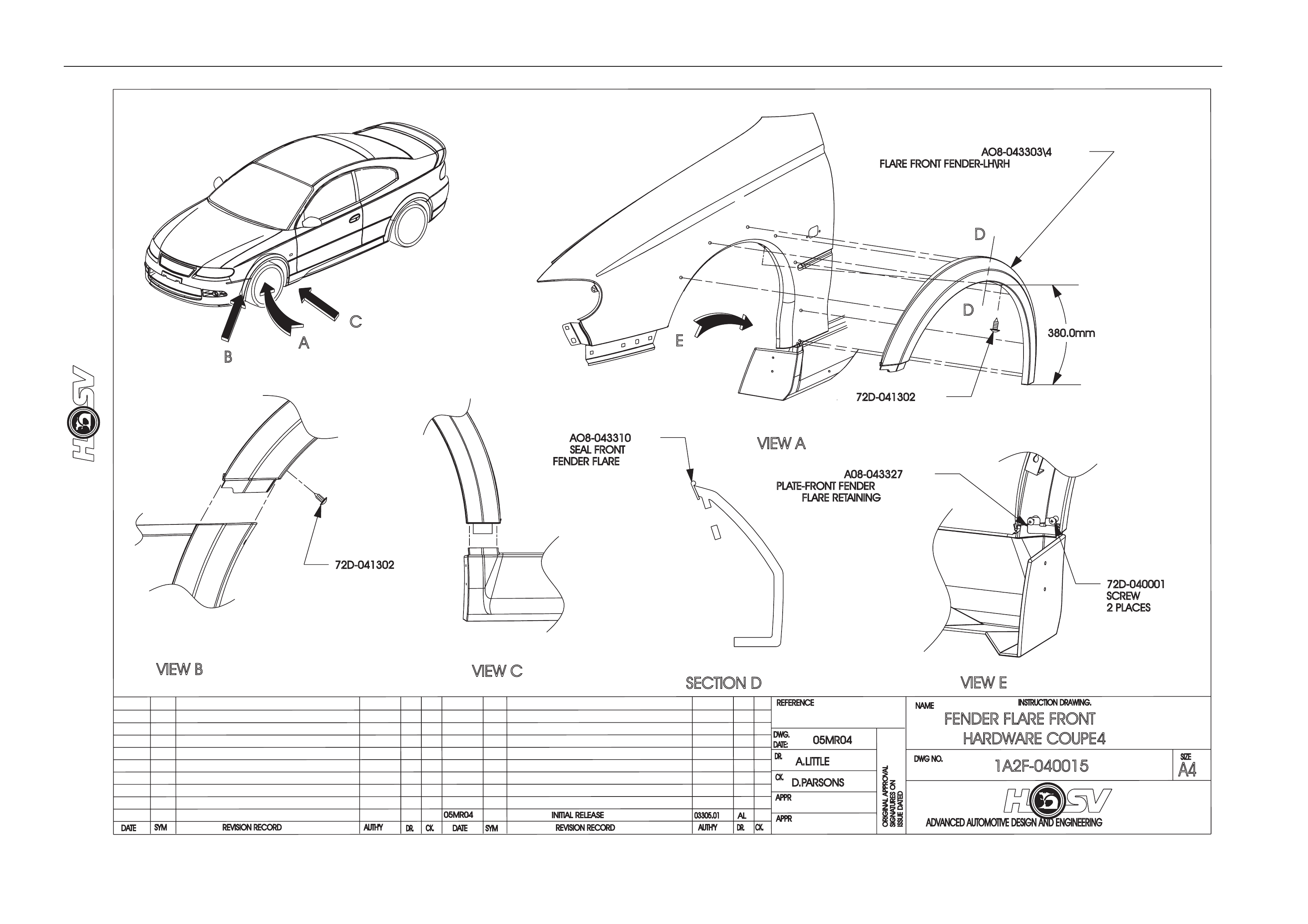
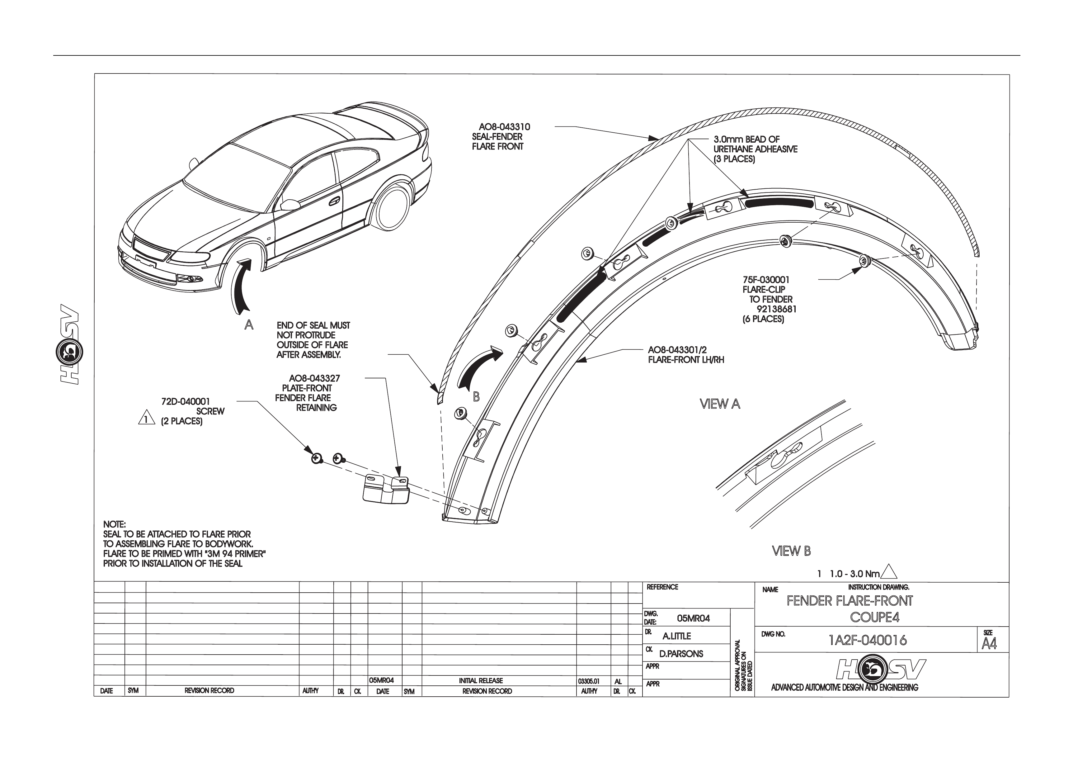
A08-043301P 1 FLARE FRONT FENDER LH 7
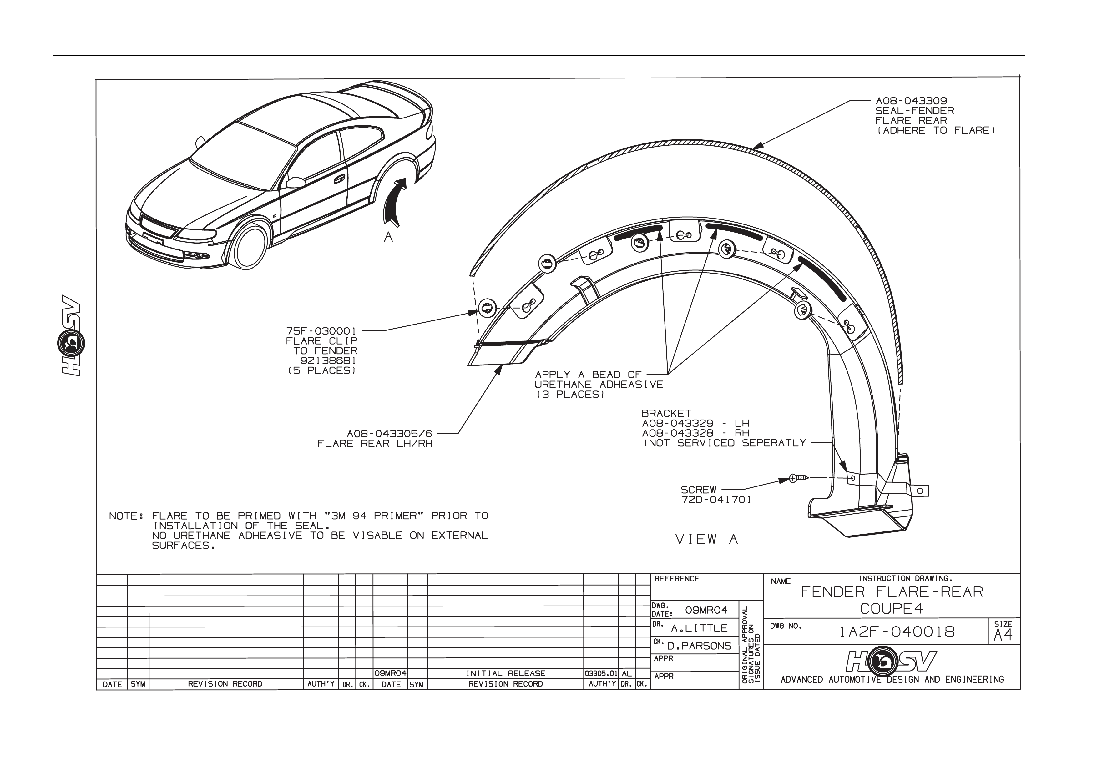
A08-043305P 1 FLARE REAR FENDER LH 8
A08-043306P 1 FLARE REAR FENDER RH 9
A08-043302P 1 FLARE FRONT FENDER RH 10
E08-021104P 1 SPOILER ROOF 11
E08-031102P 1 SPOILER REAR DECKLID RH 12
E08-031101P 1 SPOILER REAR DECKLID CENTRE 13
E08-031103P 1 SPOILER REAR DECKLID LH 14
E08-043301 1 BADGE COUPE 4 15
E08-031108B8 1 BADGE HSV CORP LOGO 16
13C-043303 1 MESH GRILLE UPPER 17
13C-043304 1 BOSS GRILLE BADGE MOUNT 18
13C-043302 1 BAR GILLE LOWER 19
14A1043303 1 MESH FRONT FACIA 20
E08-970309 1 DECAL “I JUST WANT ONE” 21
Body Page B-12
COUPE 4
ADVANCED AUTOMOTIVE DESIGN AND ENGINEERING
BODY - ORNAMENTATION
COUPE 4
25.05.04
AP
D.P
1A2F040028
1
2
3
4
5
6
7
8
9
10
11
12
13 14
15
16
17
18
20
21
19

Body Page B-13
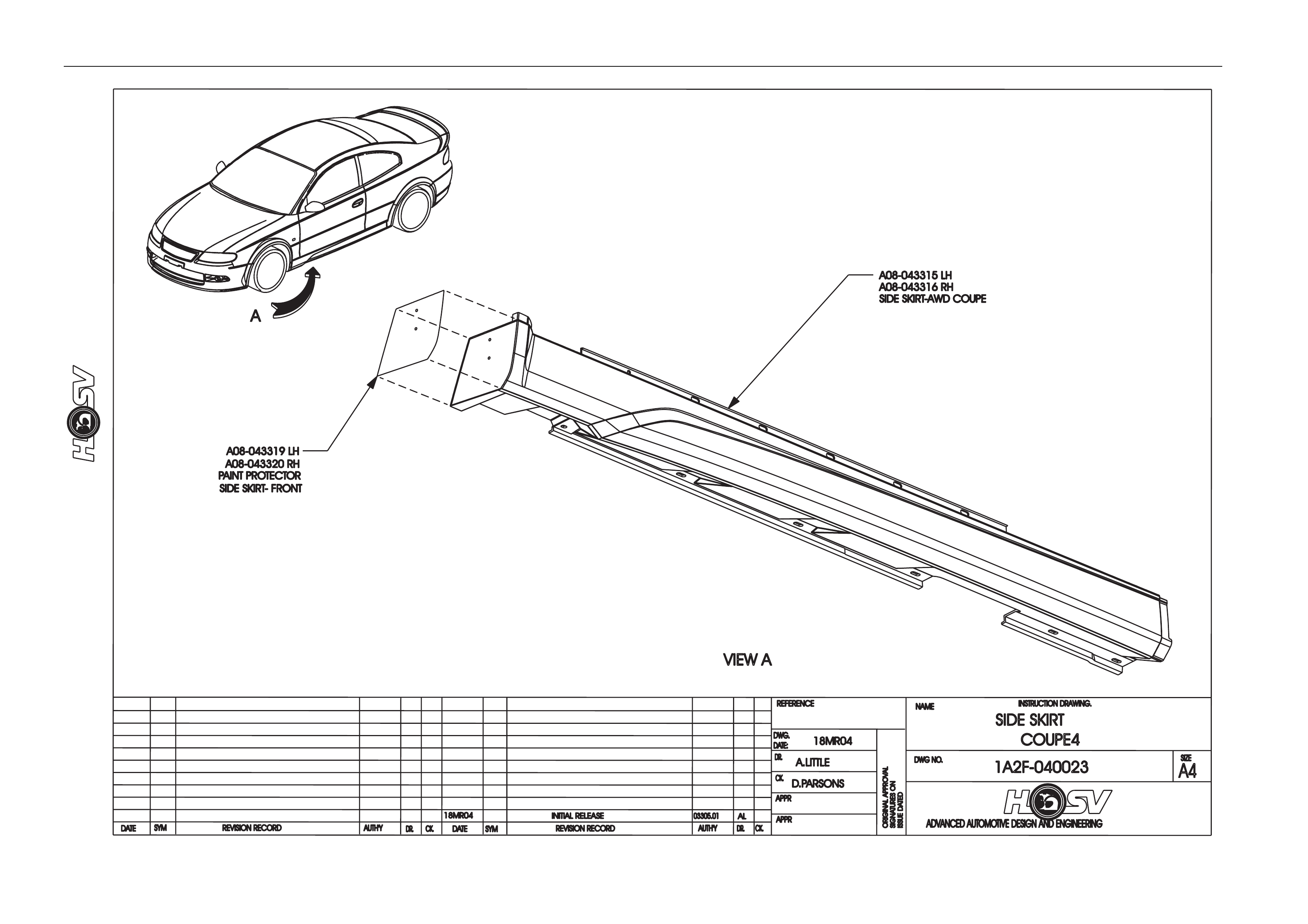
4.2 Paint Protectors
Part Number Description Quantity Reference
14A2043304 Paint Protector – Rear RH 1 1
A08-043312 Paint Protector – Rear Flare RH 1 2
A08-043322 Paint Protector – Side Skirt Rear - RH 1 3
14A2043306 Paint Protector – Rear Flare Outer - RH 1 4
A08-043314 Paint Protector – Front Flare RH 1 5
A08-043320 Paint Protector – Side Skirt Front - RH 1 6
14A1043306 Paint Protector – Front RH 1 7
14A1043305 Paint Protector – Front LH 1 8
A08-043313 Paint Protector – Front Flare LH 1 9
A08-043319 Paint Protector – Side Skirt Front - L H 1 10
14A2043305 Paint Protector – Rear Flare Outer - LH 1 11
A08-043311 Paint Protector – Rear Flare LH 1 12
A08-043321 Paint Protector – Side Skirt Rear - LH 1 13
14A2043303 Paint Protector – Rear LH 1 14
Body Page B-14
PAINT PROTECTORS COUPE 4PAINT PROTECTORS COUPE 4
ADVANCED AUTOMOTIVE DESIGN AND ENGINEERINGADVANCED AUTOMOTIVE DESIGN AND ENGINEERING
BODY - ORNAMENTATIONBODY - ORNAMENTATION
COUPE 4COUPE 4
25.05.04
AP
D.P
1A2F040029
1234
5
6
7
89
10 11
12
13 14
Body Page B-15
77B-691901
RIVET (SCRIVET)
SP3914
(2 PLACES)
92138774
SCREW
(3 PLACES)
2
1
2
3.0 - 5.0 Nm
1.0 - 3.0 Nm
14A1991316
BRACKET-RH
CENTRE SECTIONO
F
FRONT FACIA REINFORCEMENT
TOBE PAINTED BLACK
REVISION RECORD
AUTH'Y
DR.
DATE
SYM
16MR04 INITIAL RELEA
72C-671901
SCREW
(3 PLACES)
REVISION RECORD
SYM
DATE
CK.
SE
14A1043301
F
1ACIA FRONT CO
AL
03305.01
DR.
AUTH'Y
16MR04
77B-691901
RIVET (SCRIVET)
SP3914
(4 PLACES)
72D-970601
SCREW
(4 PLACES)
2
14A1991315
BRACKET-LH
11072643
SCREW
(2 PLACES)
A.LITTLE
UPE4
D.PARSONS
CK.
CK.
REFERENCE
DWG.
DR.
DATE:
APPR
APPR

Body Page B-16
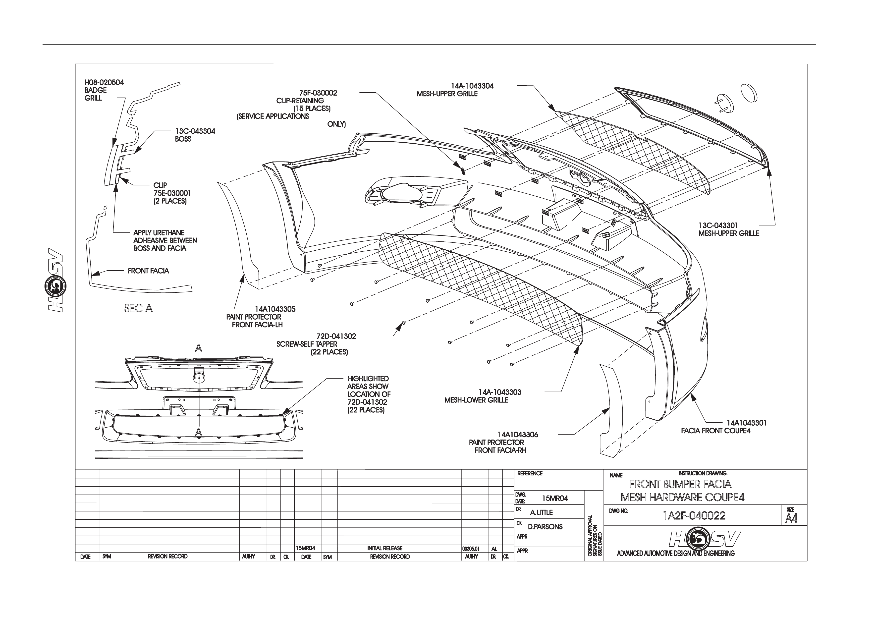
4.3 Radiator Grille Service Information
General
The Radiator Grille comprise s a Chrome Gri lle Surround and Metal Mesh Insert.
Grille Surround Attachment
Clip attachment
The Production Grille Surround is attached to the Bumper Facia with Tabs that Protrude through slots in the Facia. The
Tabs are “Heat Staked” (heated and bent) behind the inside face of the Facia. Refer to the production Facia Assembly.
The service replacement part is supplied with attaching clips these attach to the tabs. The Surround must also be
attached to the Facia with Urethane Adhes ive in at least 4 places (top, bottom and both sides) if the clips are used. No
Adhesive is to be visible on external surfac es.
Heat Stake
It is quite acceptable to Heat Stake the Grille Surround to the F ront Bumper Facia if care is taken. Refer to the production
Facia Assembly before attempting assembly of the components.
The Grille Surround Attaching Tabs are heated with a soldering Iron or similar to allow them to be bent over the inside
face of the Bumper facia. The heat applied is to be sufficient to allow the tab to bend without damaging the Chrome front
face but not enough to burn the Surround Tab material.
Grille Mesh
The Grille Mesh is assembled to the inside of the Front Bumper Facia. The Mesh is retaine d with Clips along the Top and
Screws at the sides and bottom. The mesh locates forward of the Grille Badge Mou nting Leg and must be installed
before the grille badge Mounting Boss.
Grille Badge Mounting Boss and Badge
The Mounting Boss is attached to the Facia with 2 Mounting Pins which locate in holes in the Front Facia Grille Badge
Mounting Leg.
Urethane Adhesive is applied to the Grille Mounting Leg, Mesh and Mounti ng Boss (rear face), the Boss Pins are then
pushed through the holes and 2 Clips are used to attach the Boss. The Urethane will take 24Hrs. for full strength cure.
No Adhesive is to be visible on external surfaces.

Body Page B-17
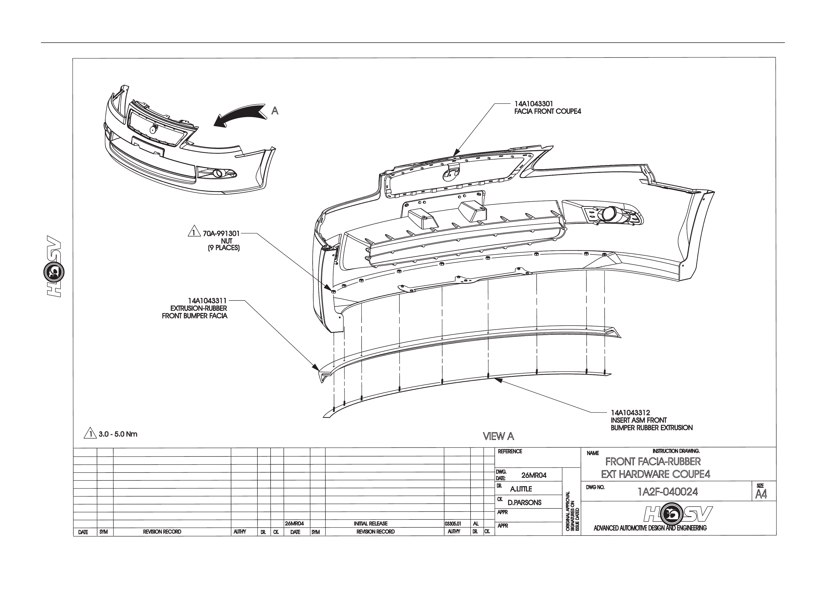
4.4 Fog Lamp Surround Service Information
General
The Fog Lamp Surrounds are “Chrome Plated” parts that locates in the Fog Lamp Recess’s of the Front Bumper Facia.
There are 2 Surrounds a RH Surround and a Left Hand Surround. These are fitted after painting and after the Fog Lamp
Recess Black Decals have been fitted.
Fog Lamp Surrounds Attachment
Clip Attachment.
The Production Fog Lamp Surr ound is attached to the Bumper Facia with Tabs that Protrude throu gh slots in the Facia.
The Tabs are “Heat Staked” (heated and bent) behind the inside face of the Facia. Refer to the producti on F acia
Assembly. The service replacement part is s upplied with attaching clips these attach to the tabs. The Surround must also
be attached to the Facia with Urethane Adhesive in at least 4 places (top, bottom and both sides) if the clips are used.
No Adhesive is to be visible on external surfaces.
Heat Stake.
It is quite acceptable to Heat Stake the Fog Lamp Surround to the Front Bumper Facia if care is taken. Refer to the
production Facia Assembly before attempting assembly of the components.
The Fog Lamp Surround Attac hin g Tabs are heated with a Soldering Iron or similar to allow them to be bent over the
inside face of the Bumper facia. The heat applied is to be sufficient to just allow the tab to bend without damaging th e
Chrome front face but not enough to burn the Surround Tab material.

Body Page B-18
4.5 Fog Lamp Recess Decal Installation
General
The Fog Lamp Recess decals are Black and are located in the Bottom of the Fog Lamp Recesses. They are handed an d
also inner and outer parts. Make sure the correct part is identified before attempting assembly.
Fog Lamp Recess Decal Installation
1. The Decals are installed after the Facia is pai nted.
2. The paint finish in the bottom of the recess must be smooth and free of “over spray”.
3. The Decals are supplied with a “peal off” protective film on the adhes ive surface.
4. The bottom must be cleaned and free of polish prior to fitment.
5. Warming the Facia and Decal will enhance the adhesive bond.
The slots in the Decals are to align with the slots in the Bumper Facia.
Body Page B-19
ADVANCED AUTOMOTIVE DESIGN AND ENGINEERING
INSTRUCTION DRAWING.
A4
SIZE
REVISION RECORD
CK.
NAME
DWG NO.
CK.
REFERENCE
DWG.
DR.
DATE:
APPR
APPR
DR.
AUTH'Y
REVISION RECORD
AUTH'Y
SYM
DATE
DR.CK.
DATE
SYM
ORIGINAL APPROVAL
SIGNATURES ON
ISSUE DATED
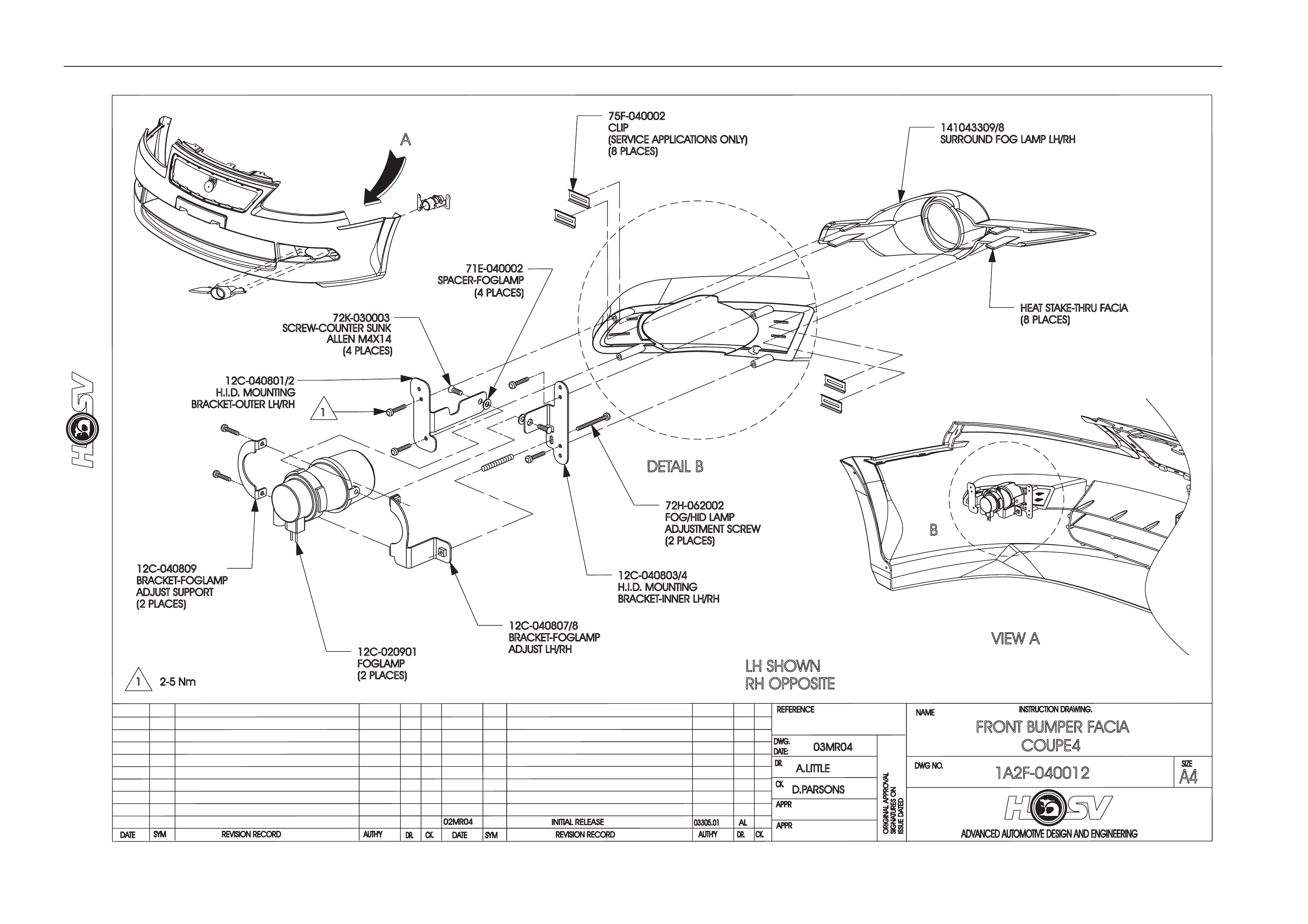
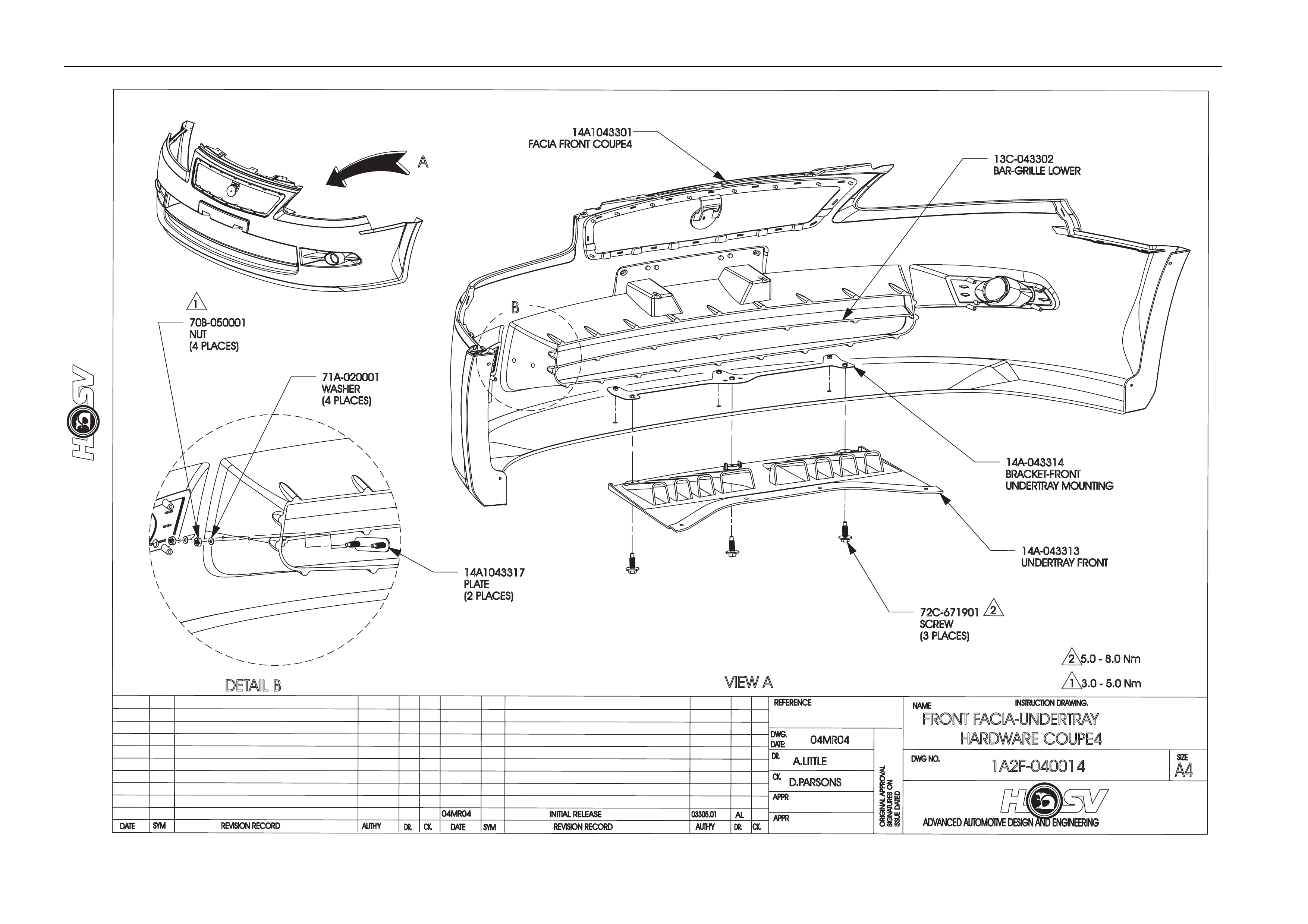
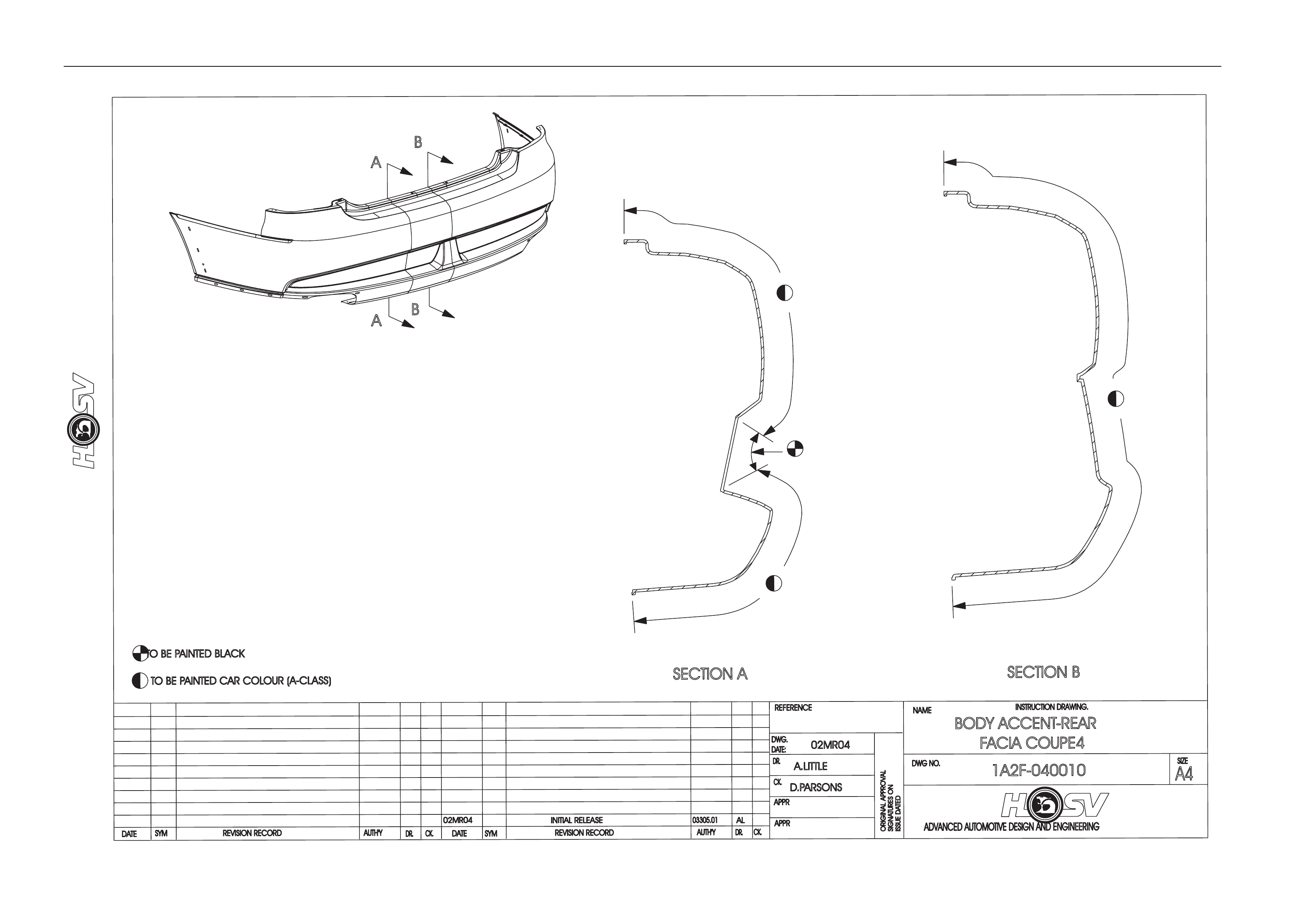
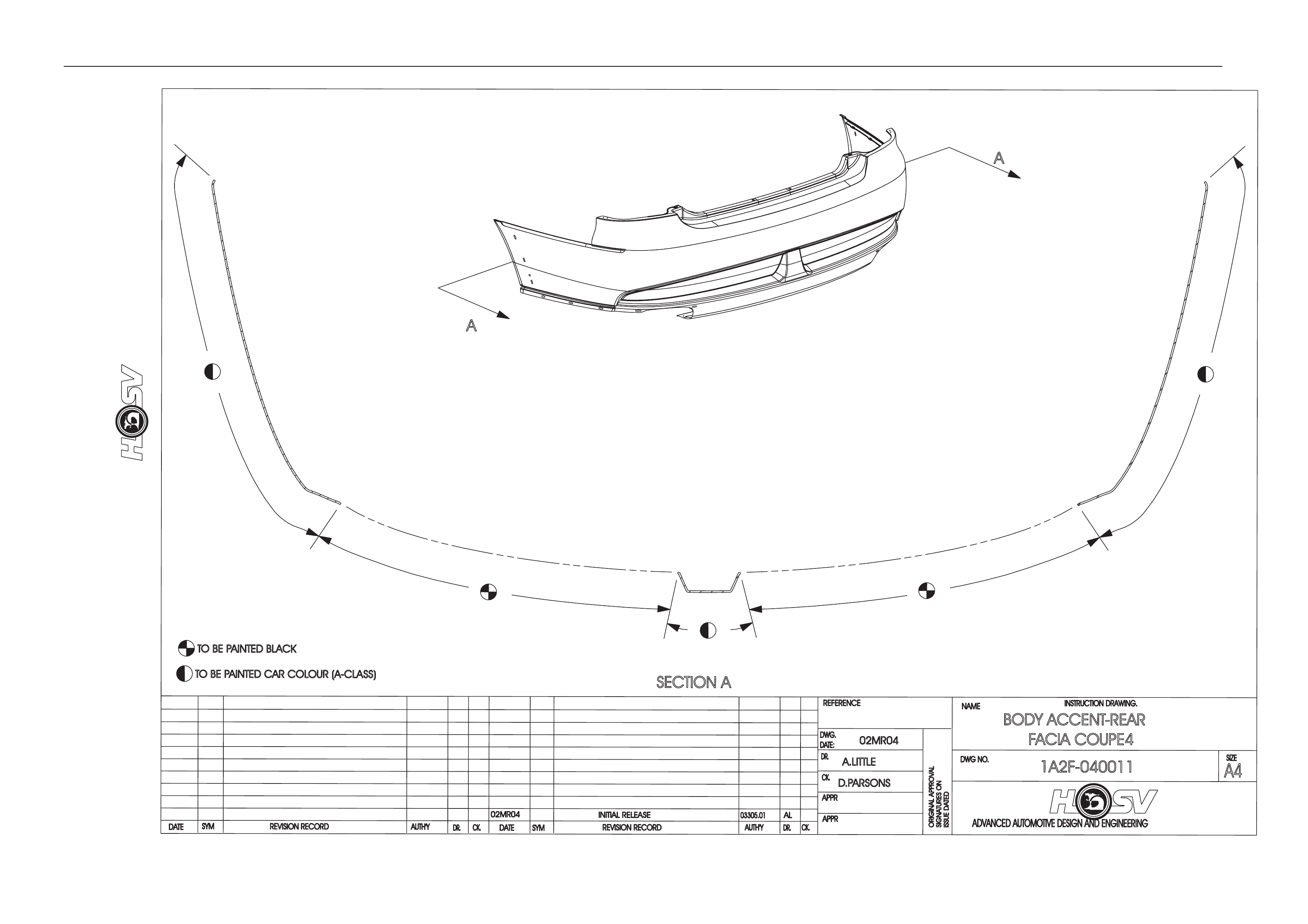
03MR04
02MR04 INITIAL RELEASE
A.LITTLE
FRONT BUMPER FACIA
COUPE4
1A2F-040012
VIEW A
A
DETAIL B
B
141043309/8
SURROUND FOG LAMP LH/RH
12C-040809
BRACKET-FOGLAMP
ADJUST SUPPORT
(2 PLACES)
12C-020901
FOGLAMP
(2 PLACES)
12C-040803/4
H.I.D. MOUNTING
BRACKET-INNER LH/RH
12C-040807/8
BRACKET-FOGLAMP
ADJUST LH/RH
12C-040801/2
H.I.D. MOUNTING
BRACKET-OUTER LH/RH
71E-040002
SPACER-FOGLAMP
(4 PLACES)
72H-062002
FOG/HID LAMP
ADJUSTMENT SCREW
(2 PLACES)
72K-030003
SCREW-COUNTER SUNK
ALLEN M4X14
(4 PLACES)
HEATST
AKE-THRU FACIA
(8 PLACES)
1
1 2-5 Nm
75F-040002
CLIP
(SERVICE APPLICATIONS ONLY)
(8 PLACES)
LH SHOWN
RH OPPOSITE
D.PARSONS
AL
03305.01
Body Page B-20
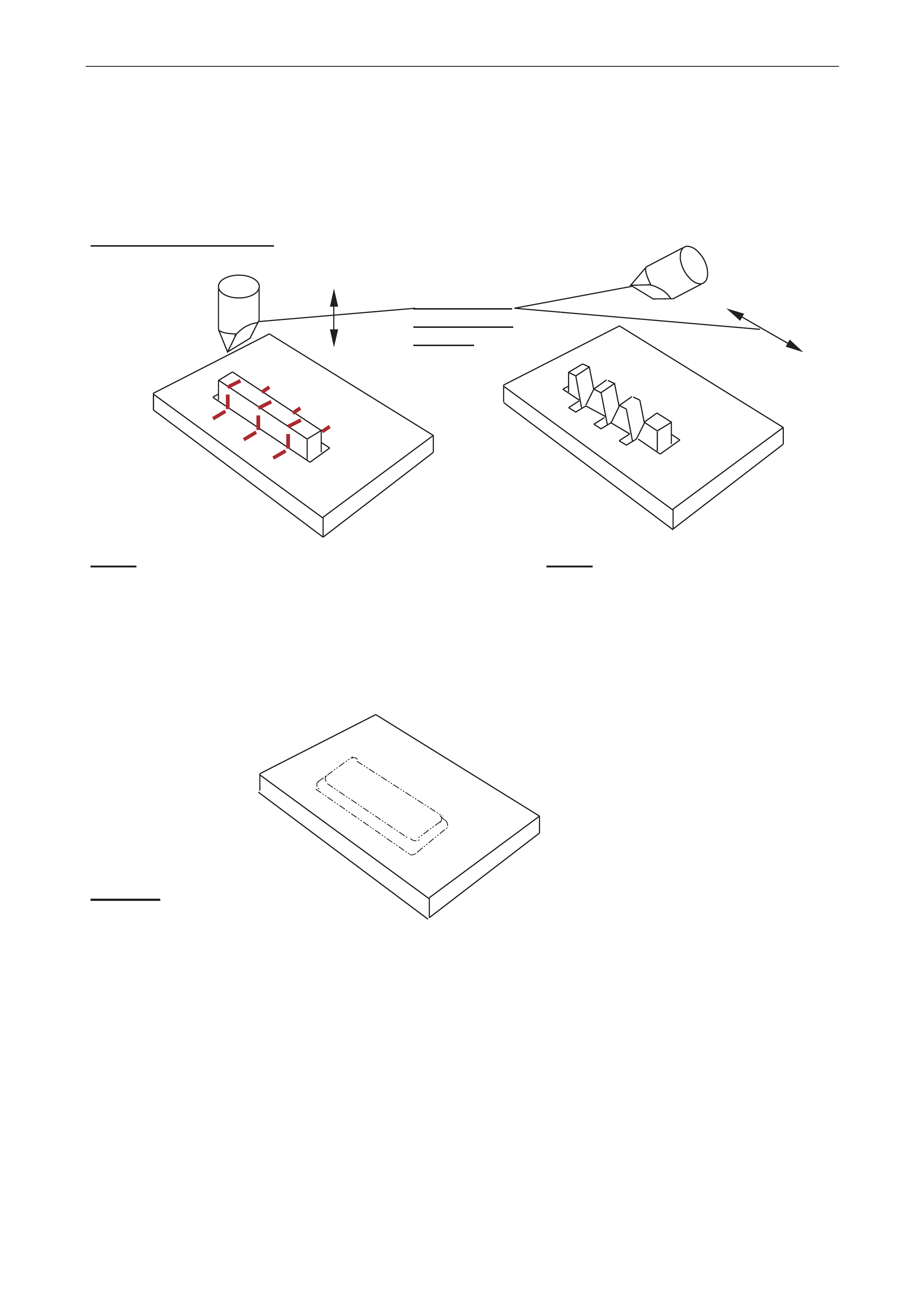
Heat Staking Procedure.
Step 1 Step 2
Melt material across blade and into base in Smooth and fill initial cuts
leaving material proud of base to avoid excess
several places taking care not to thinning over joint
distort outer visible surface
Finished
Soldering Iron
and movement
direction
Body Page B-21
Body Page B-22
Body Page B-23
Body Page B-24

Body Page B-25
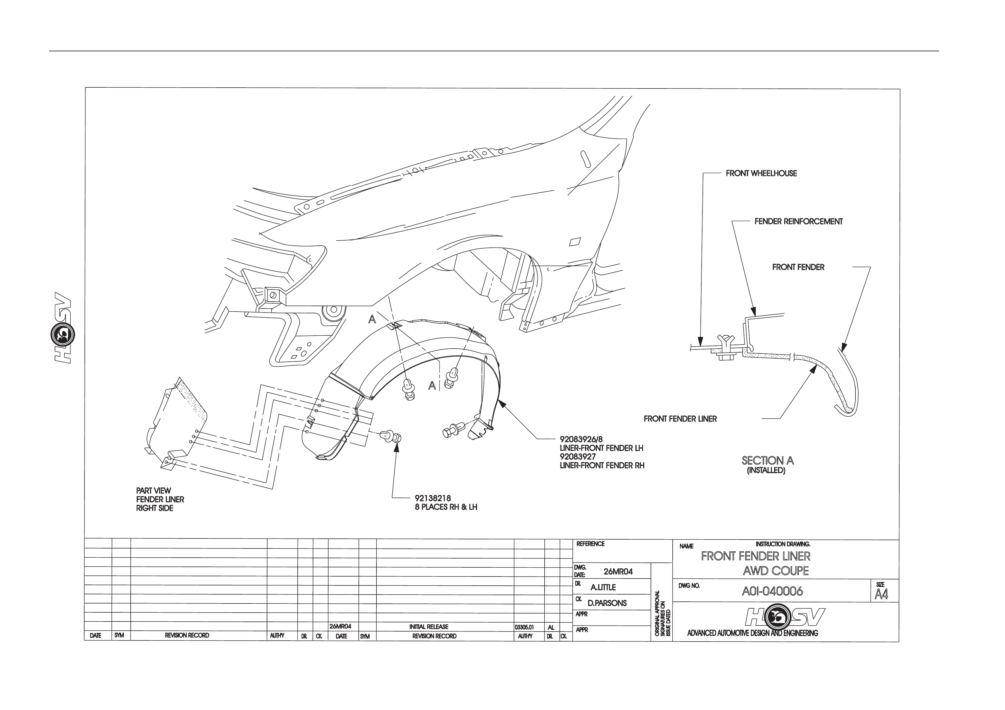
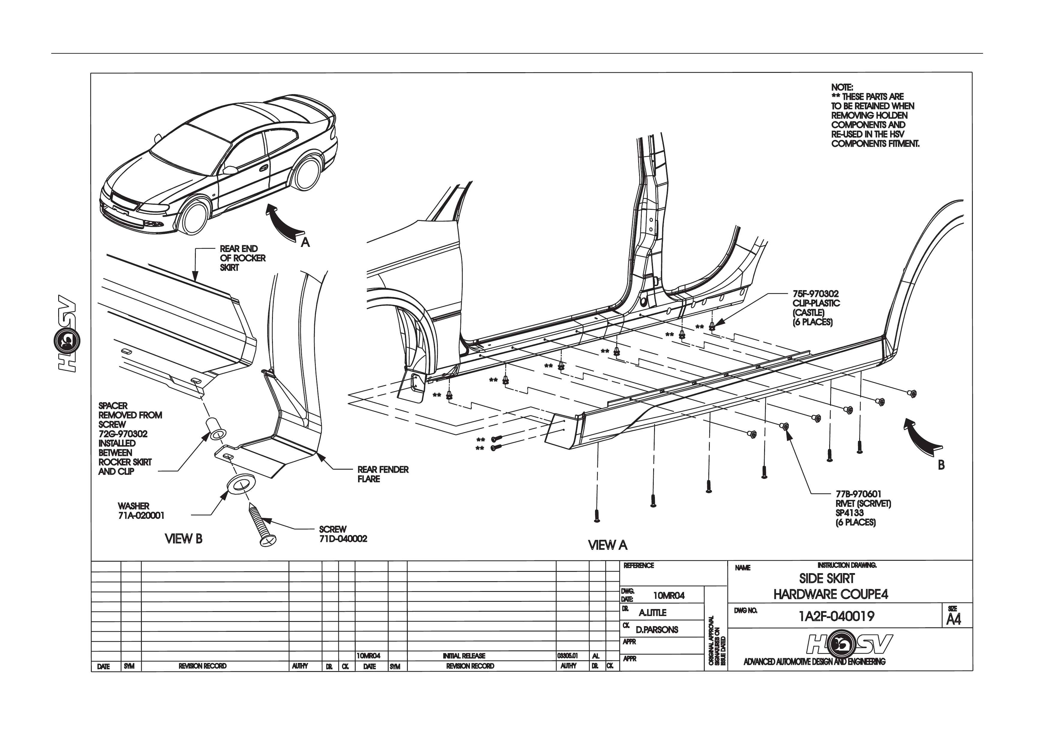
4.6 Front Fender Liner Service Information
Removal
1. Remove The Rocker Skirt.
2. Remove the Upper Front attaching Scrivet.
3. Remove the Lower Front Facia to Fender Liner attachin g Screw.
4. Remove the Fender Liner to Body Side Rail attaching Screw For the Left Han d Side Liner or The Lower Front
Scrivet for the Right Hand Side Liner.
5. Remove the Fender Liner to Front Flare Screw.
6. Carefully push the liner inside the Wheelhouse to remove it from the Body.
Installation
1. Installation is the reverse procedure of removal except if new Body Panels have been fitted.
2. When new Panels have be en fitted the Liner must be fitted after the front Fender Flares, but prior to fitting the Side
Skirt.
3. Install the Liner into the Wheel house making sure the outer edge of the liner stays inside the Front Flare Flange.
4. Install the Upper liner to wheelhouse Scrivet, use a Screw Driver or similar to hold the attaching tab against the
panel to install the Scrivet.
5. Drill the Front Flare to Liner attaching Screw if a new Fare is used. Refer to the Front Flare fitting instructions and
Drawing 1A2F-040015.
6. Rotate the top outer edge of the Liner outboard to ensure sufficient overlap of the liner with the Flare Flange and
hold in this position while installing the Liner to flare attaching Screw, use a Power Screw Driver or similar, the
Screw will make it’s own hole. Take care not to over tighten the Screw.
7. Install the Side Skirt.
Body Page B-26
Body Page B-27
Body Page B-28
Body Page B-29
Body Page B-30
ADVANCED AUTOMOTIVE DESIGN AND ENGINEERING
INSTRUCTION DRAWING.
A4
SIZE
REVISION RECORD
CK.
NAME
DWG NO.
CK.
REFERENCE
DWG.
DR.
DATE:
APPR
APPR
DR.
AUTH'Y
REVISION RECORD
AUTH'Y
SYM
DATE
DR.CK.
DATE
SYM
ORIGINAL APPROVAL
SIGNATURES ON
ISSUEDA
TED
15MR04
15MR04INITIAL RELEASE
A.LITTLE
REAR BUMPER FACIA
HARDWARE COUPE4
1A2F-040021
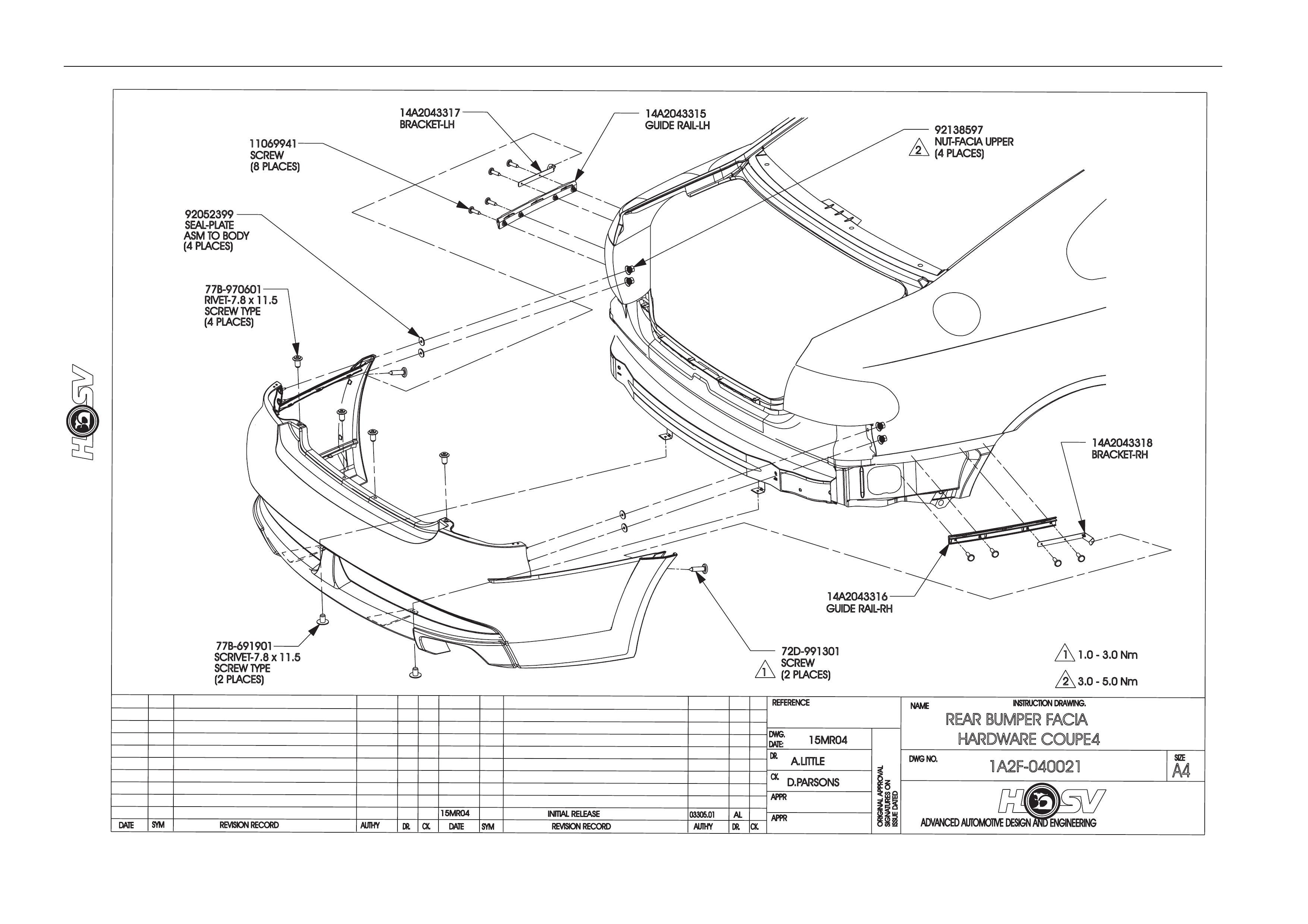
77B-970601
RIVET-7.8 x1
1.5
SCREW TYPE
(4 PLACES)
77B-691901
SCRIVET-7.8 x1
1.5
SCREW TYPE
(2 PLACES)
92138597
NUT-FACIA UPPER
(4 PLACES)
92052399
SEAL-PLATE
ASM TOBODY
(4 PLACES)
D.PARSONS
03305.01
AL
72D-991301
SCREW
(2 PLACES)
14A2043316
GUIDE RAIL-RH
14A2043315
GUIDE RAIL-LH
14A2043317
BRACKET-LH
14A2043318
BRACKET-RH
11.0 -3
.0 Nm
23.0 -5
.0 Nm
2
1
11069941
SCREW
(8 PLACES)
Body Page B-31
DATE
ISSUEDATED
AUTH'Y
CK.
SYM
AUTH'Y
REVISION RECORD
DATE
SYM
SIGNATURESO
N
ORIGINAL APPROVAL
DR.
ADVANCED AUTOMOTIVE DESIGN AND ENGINEERING
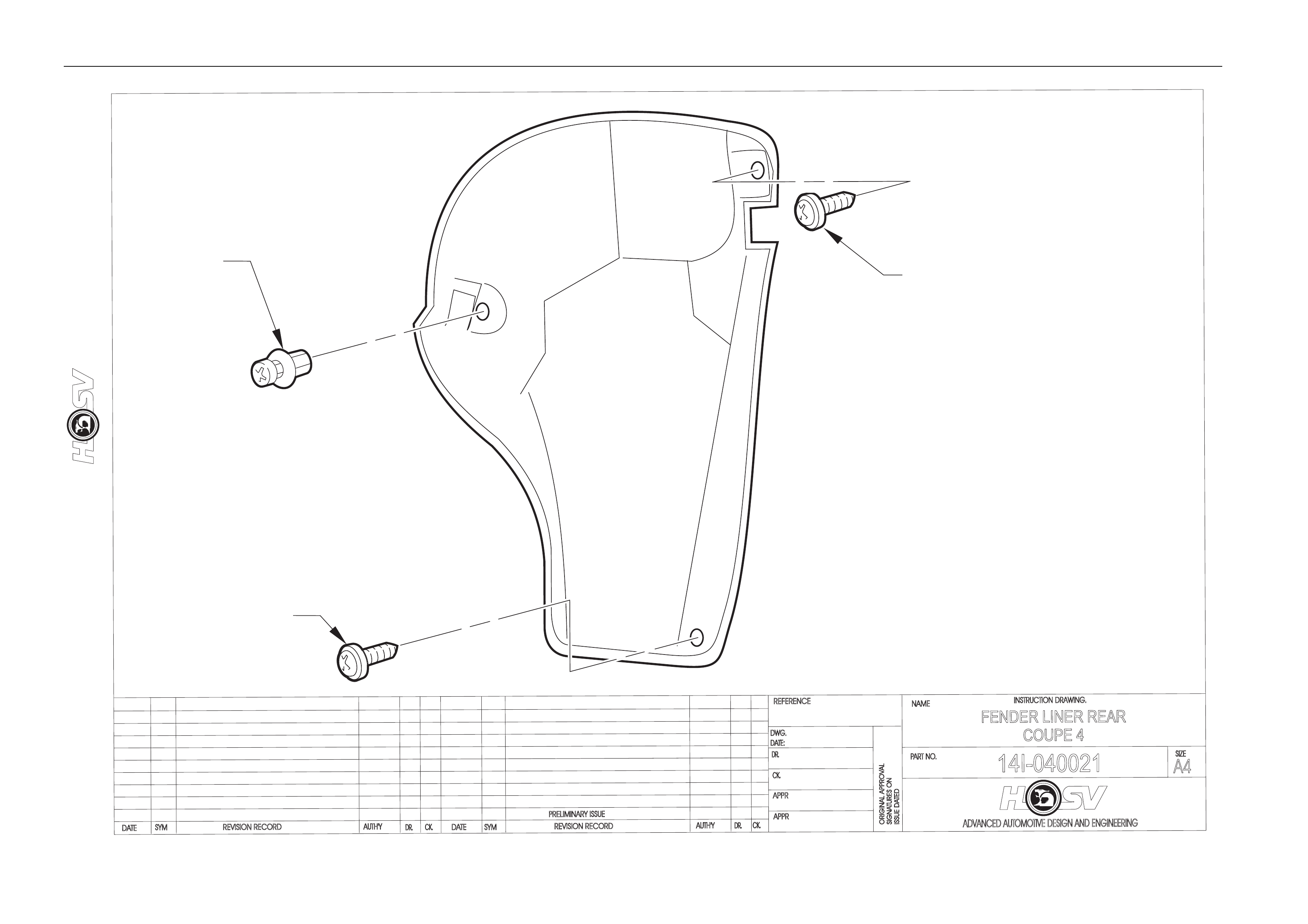
14I-040021
INSTRUCTION DRAWING.
A4
SIZE
FENDER LINER REAR
COUPE 4
REVISION RECORD
PRELIMINARY ISSUE
CK.
NAME
PART NO.
CK.
REFERENCE
DWG.
DR.
DATE:
APPR
APPR
DR.
20SEP04
AP
DP
DP
SCREW
72D-041302
(USE AS TEMPLATE TO
DRILL 3.2mm HOLE
IN FLANGE WITH NEW PANEL.)
SCREW
72D-991301
(LOWER EDGE
REAR FACIA)
SCRIVET
77B-691901
NOTE : RHS SHOWN LHS OPPOSITE

Body Page B-32
4.7 Rear Fender Liner Service Instruction
Removal
1. Remove lower Rear Facia to Fender Liner attachin g Screw.
2. Remove Upper Fender Liner to Rear Fender Flange attaching Screw.
3. Remove Fender Liner to Wheel house Inner Panel attaching Scrivet.
4. Remove Fender Liner by rotating upper edge of liner forward and down, this will disengage the loc atin g tab away
from lower Wheelhouse flang e and a llow the Liner to be removed.
Installation
1. Installation is the reverse procedure of removal except if new Body Panels have been fitted.
2. When new Panels have been fitted install the Rear Fender Liner and use the existing Upper Fender L iner to Rear
Fender Flange attaching Screw Hole as a template to drill a 3,2 diameter hole in the Rear Fender Flange. Take
care not to damage the paint finish on the Rear Fender Flare when drilling.
3. Apply Zinc Rich Primer to the drilled hole and install the attaching Screw.
4. Using the lower Facia attaching ho le as a guide to install the lower Liner to Facia attachi ng Screw, install the Screw
using a power Screw Driver or similar, the Screw will produce it’s own hole.
Body Page B-33
Body Page B-34
Body Page B-35
Body Page B-36
Body Page B-37
Body Page B-38
Body Page B-39
Body Page B-40
Body Page B-41
DATE REVISION RECORD
RELEASE
SYM DR.
AUTH'Y CK.
MB
-
DWG.
DATE:
30.04.03
DP
LH
COUPE 2
-
REAR DECKLID SPOILER
- COUPE 2 - TYPE 2
E0I - 030008
INSTRUCTION DRAWING.
E08-031102
SPOILER-RR DECKLID
RH-COUPE
72G-062501
STUD
(5 PLACES)
E03-021104
(2 PLACES)
E03-021102
(2 PLACES)
72A-052502
SCREW PAN HEAD
M6 x 10 (4 PLACES)
GASKET (PARTOF
LAMP ASSEMBLY)
12E-031105
STOP LAMP
72A-111903
(2 PLACES)
E08-031101
SPOILER-RR DECKLID
CENTRE COUPE
HOLES TOBE
SEALED WITH
URETHANE SEALER
A
B
VIEW B
VIEW A
71A-070201
M6 x 10 SMALL WASHER
(11 PLACES)
79B-970303
TERMINAL
(2 PLACES)
T213021102
(SEALING TAPE)
70B-060001
M6x10NUT
(9 PLACES)
E09-970601
(4 PLACES)
E03-021103
(BRACKET)
E08-031103
SPOILER - RR DECKLID
LH - COUPE
URETHANE
SEALER
(2 PLACES)
71A-020001
WASHER
(2 PLACES)
70A-991301
NUT
(2 PLACES)
77A-020401
STUD
(2 PLACES)
ECN O2113.03
E09-070601
(5 PLACES)

Body Page B-42
5 Rear Spoiler Type 2
ATTENTION
Before performing any service operation or other procedure described in this section refer to Section 00
CAUTIONS AND NOTES for correct workshop practices with regard to safety and/or property damage.
5.1 Service Operations
Refer drawing E0I-0I0008
Spoiler Ends
Removal
1. Apply masking tape to the Rear Quarter Outer Panel. Tape is to be located hard up against the edges of the
spoiler and to extend a width of at least 100mm around the spoiler ends;
2. Open the trunk lid;
3. Peal back to side trunk lid Rear Quarter Inner Trim to gain access to the spoiler ends front attachments;
4. Remove the attaching nut and bracket;
5. Remove the two rear upper spoiler end attaching bolts and two brackets to spoiler attaching screws and flat
washers;
6. Carefully remove the spoiler and end from body work;
Installation
The installation for the spoiler ends is the rev ers of the remo val procedure.
Spoiler Centre Section
Removal
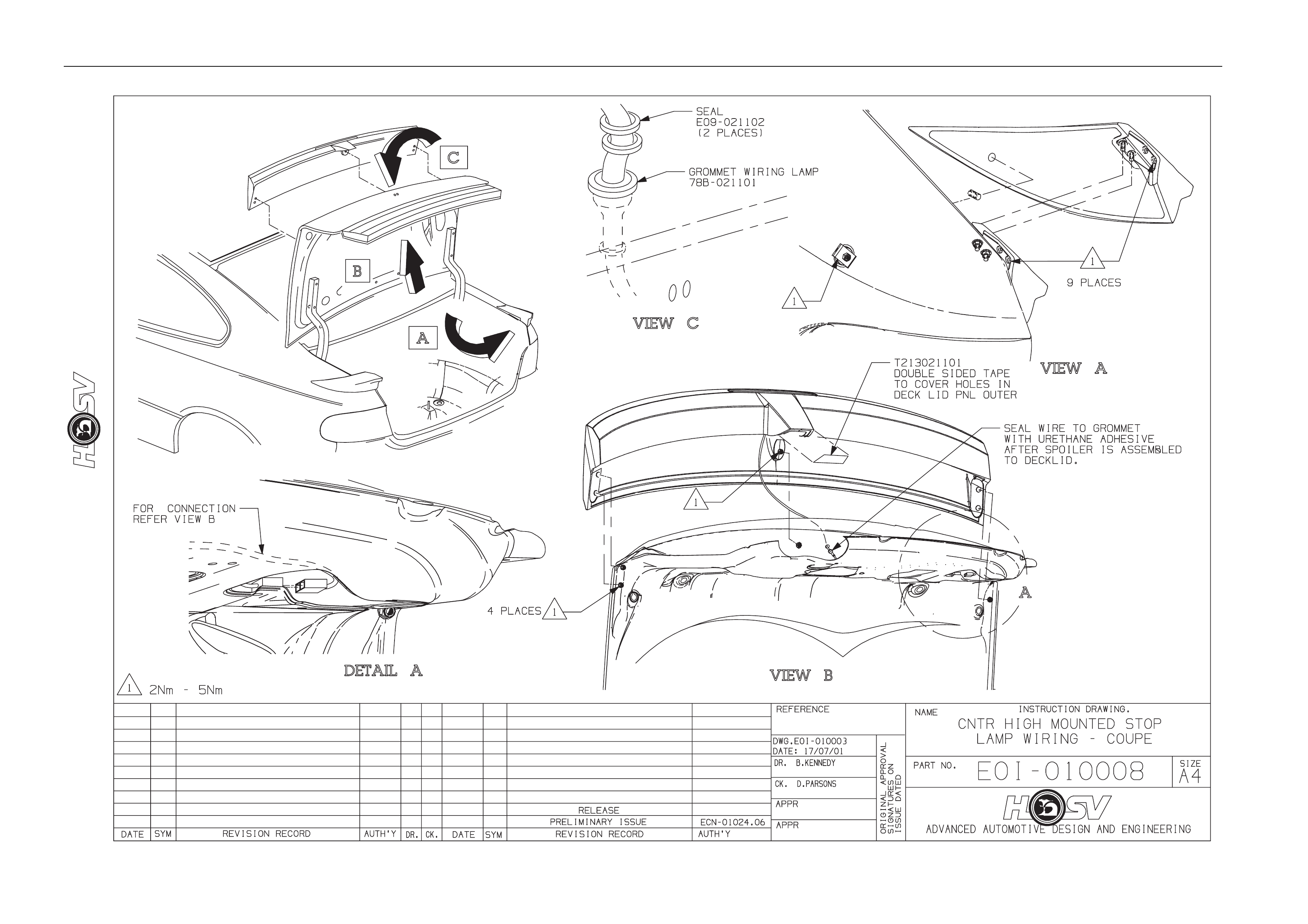
7. Remove the deck lid inner trim;
8. Remove the centre high mounted stop lamp;
9. Remove the spoiler centre mountin g flanged nut and stud;
10. Remov e the four outer attach ing nuts and washers (2 per side);
11. Remov e the mounting studs from one side of the spoiler;
12. Carefully lift the spoiler centre from the deck lid.
Installation
The installation is the revers of the removal procedure. Do not attempt to install the centre spoiler with the studs installed
in the spoiler.
Body Page B-43
Body Page B-44
Body Page B-45
5.2 HSV Coupe Rear Spoiler – New Rear
Quarter Panel and New Spoiler
These instructions explain how to achieve the correct attaching hole locations for the rear spoilers when new panels are
being used and the spoilers are damaged beyo nd using as templates as pr eviously noted.
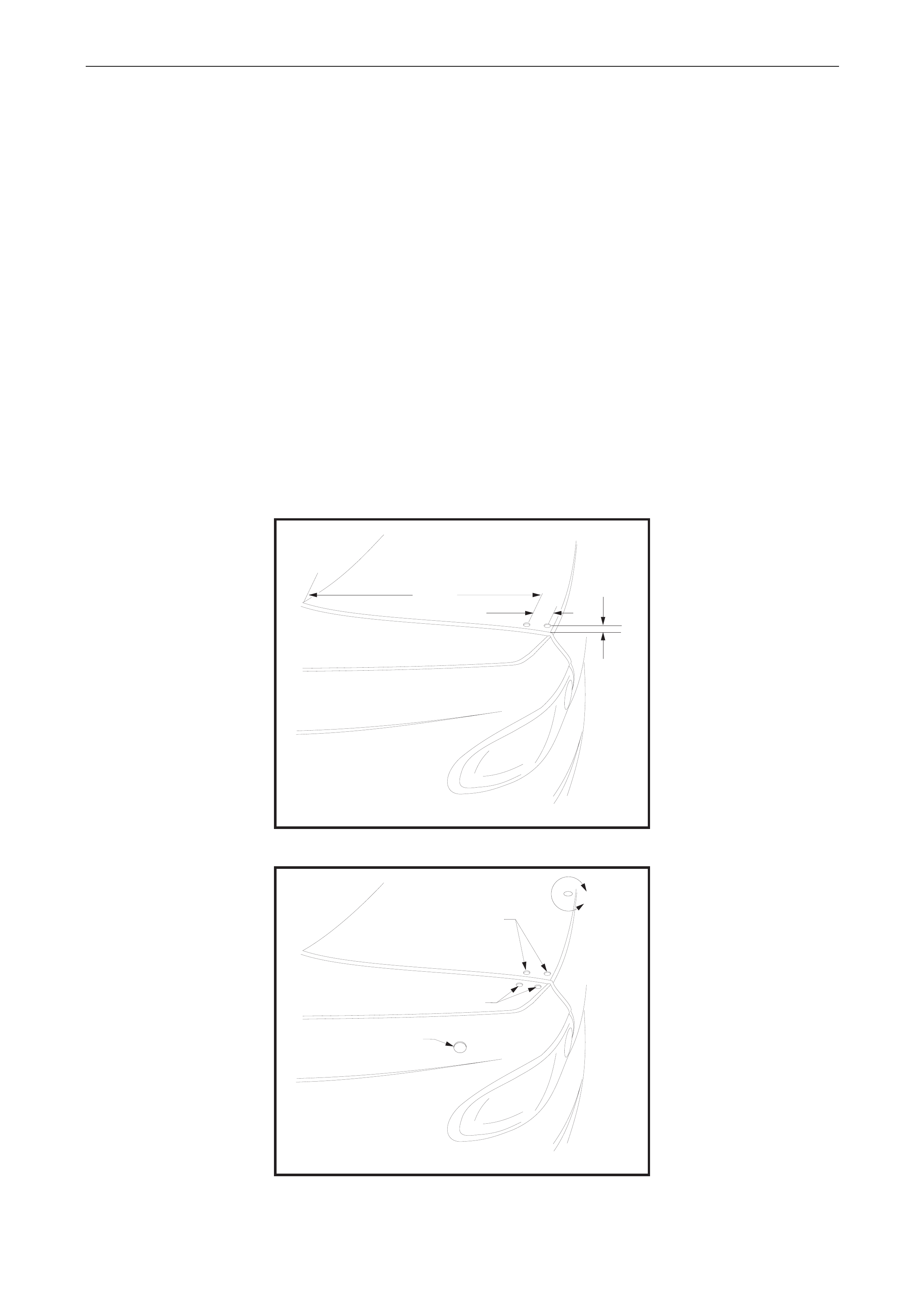
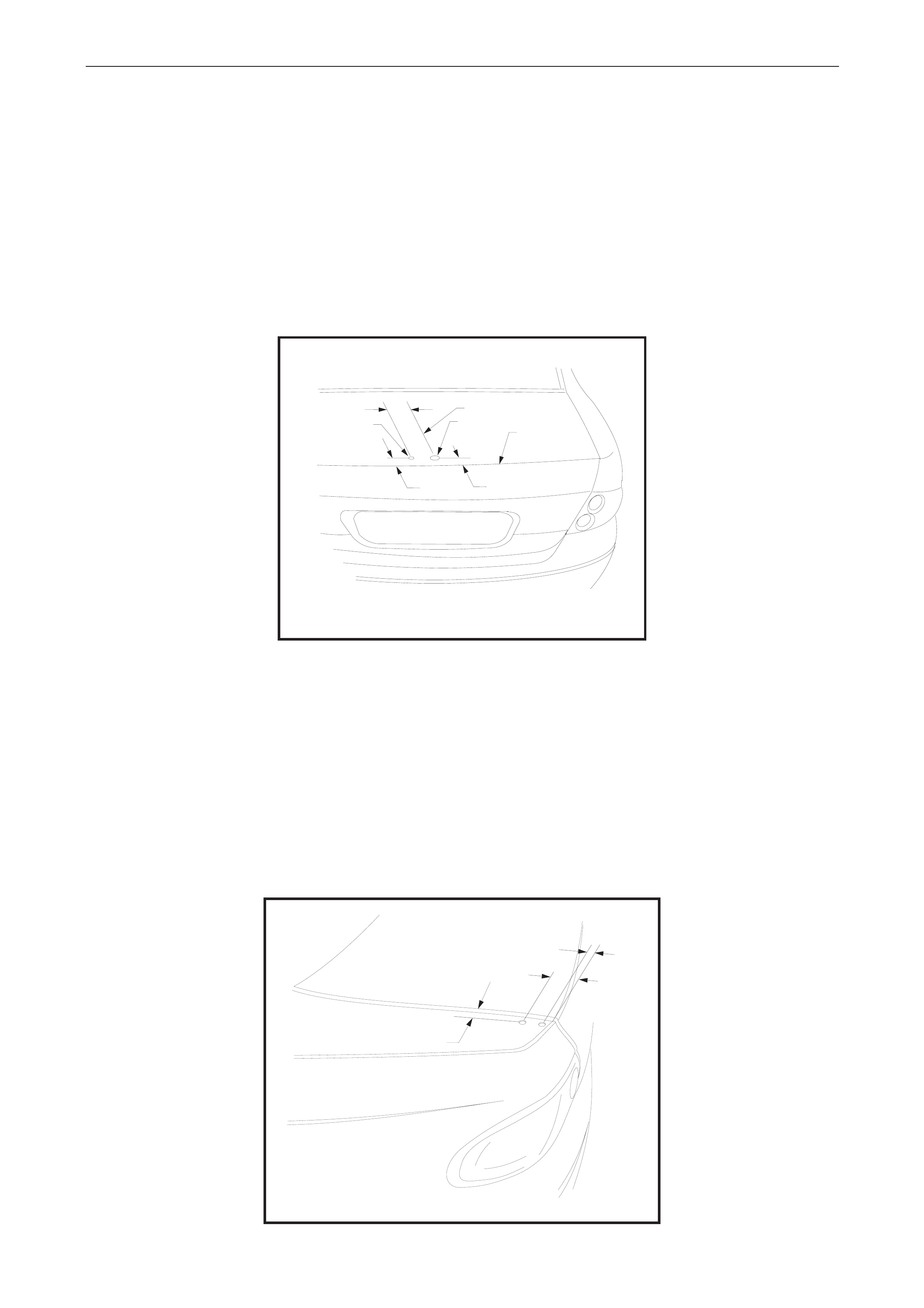
Decklid Centre Spoiler Outer Holes
Apply a 50 mm wide strip of masking tape along the outer edge of the Deck lid, both sides. The tape is to extend from the
front edge along the entire top surface.
Using a suitable pen or marker measure 18,0 mm in from the edge of the decklid and mark a line along the length of the
tape parallel to the edge.
From the front edge of the Decklid measure alo ng the line 462 mm to mark the front hole position.
Measure 20 mm in from the Decklid edge and mark a parallel lin e alo ng the last 100 mm of the Decklid top surface.
Intersect this line with a line 43 mm behind the front hole for the position of the rear hole. Refer to figure 1.
Centre punch the hole positions and carefully drill 6 mm pilot holes.
Using a step drill, open thes e holes up to 10,5 mm diameter (a 10 mm step drill produces a 10,5 diameter hole). Refer to
figure 2.
HOLE LOCATIONS IN
DECK LID OUTER PANEL
FIG 1
482.0 mm
43.0 mm
18.0 mm
DETAIL OF SPOILER
ATTACHING HOLE DIAMETERS
10.5 mm DIA. 2 HOLES
10.5 mm DIA. 2 HOLES
27.0 mm DIA. HOLE
REFER TO STEP 4 PROCEDURE
FIG 2
B
Body Page B-46
Centre Spoiler Centre Holes
Apply a 50 mm wide 100 mm long strip of masking tape in the approximate area for locatio n of the centre holes.
Working from the edges of the Decklid using a suitable pen mark the centreline of the Decklid.
From the rear edge of the Decklid measure forward 34 mm and mark the centre of the central attachi ng hole.
Draw a line parallel to and 50 mm to the right of the centerline. Intersect this line with a line 37 mm forward of the rear
edge of the Decklid for the attaching hole.
Carefully centre punch the hole positions and drill 6 mm pilot holes.
The Wiring hole is drilled to suit a 19 mm chassis punch. Refer to Figure 3
The centre attaching hole is drilled to 10,5 mm using a step drill. Refer to Figure 3
DETAIL OF SPOILER
CENTRAL ATTACHING HOLES
DECKLID REAR
UPPER EDGE
L DECKLID
C
FIG 3
37.0 mm
VIEW
B
50.0 mm
10.5 mm Dia Hole 20.0 mm Dia Hole
34.0 mm
Side Spoiler Upper Attaching Holes
Apply a 50 mm wide 100 mm long strip of masking tape in the approximate area for location of the holes.
Mark a line outboard of and p arallel to the edge of the Decklid open ing.
From the rear upper edge of the Rear Quarter Panel measure forward 31 mm and mark the rear hol e position.
From the rear upper edge of the Rear Quarter Panel measure forward 87 mm and mark the front hole positio n.
Carefully centre punch the hole positions and drill 6 mm pilot holes.
Using a step drill, open thes e holes up to 10,5 mm diameter. Refer to figure 4
HOLE LOCATIONS IN TOP
OF REAR QUARTER PANEL
87.0 mm
31.0 mm
10.5 mm
FIG 4
Body Page B-47
Side Spoiler Lower Attaching Hole
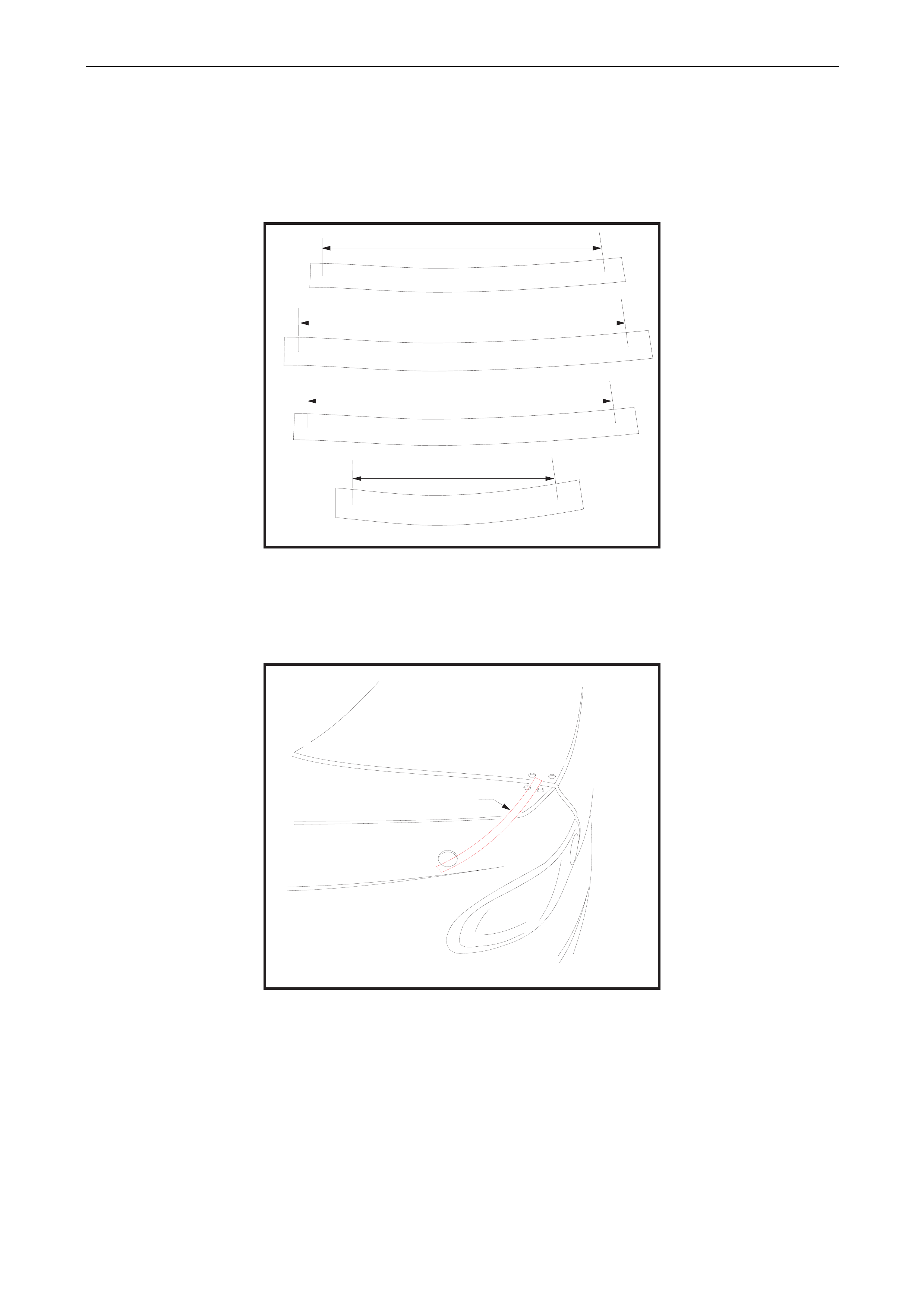
This hole is located measuring along the panel from 3 known points giving an intersection point for the hol e position.
Using 2 strips of masking tape stuck with adhesive side to side prepare 4 lengths to crea te measuring strips as sho wn
on Figure 9.
Mark these strips with the dimensions shown.
STRIP A
207,0 mm
207,0 mm
305,0 mm305,0 mm
STRIP BSTRIP B
297,0 mm297,0 mm
STRIP C
100,0 mm100,0 mm
STRIP D
FIG 9
Apply a 70 mm wide 100 mm long strip of masking tape in the approximate area for locatio n of the lower hole.
Using Strip A (207 mm distance) locate the datum mark in the centre of the front upper attaching hole and with the strip
running along the panel scribe an arc onto the tape. Refer Figure 5.
STEP 1
FOR LOCATION IN REAR
QUARTER OUTER PANEL
OF 27.0 mm DIA SPOILER HOLE FIG 5
STRIP A
Body Page B-48
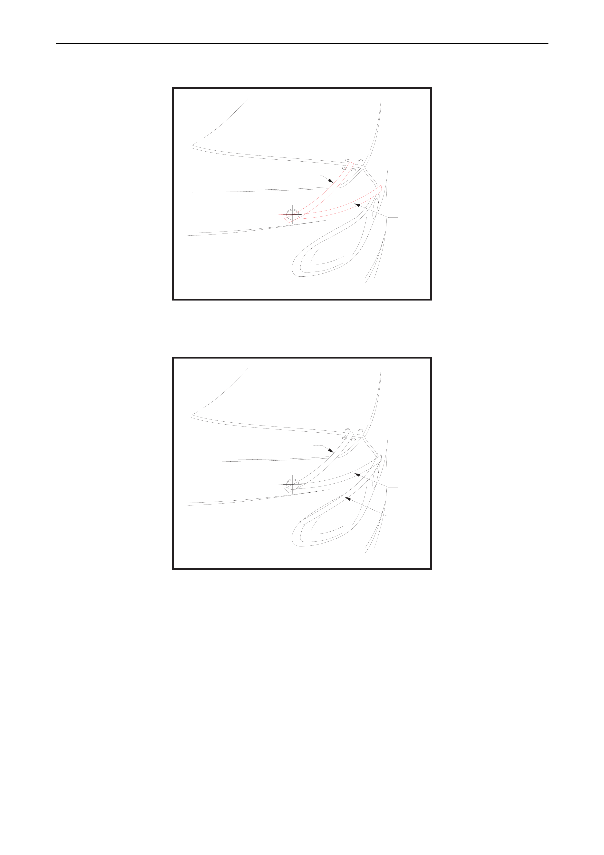
Using Strip B (305 mm distance) locate the datum mark at the intersection of the top edg e of the Tail Lamp and the Rear
Quarter Panel, with the strip running along the panel scribe another arc onto the tape. Refer Figure 6.
STEP 2
FOR LOCATION IN REAR
QUARTER OUTER PANEL
OF 27.0 mm DIA SPOILER HOLE FIG 6
STRIP A
STRIP B
Using Strip C (297 mm distance) measure along the top edge of the Tail Lamp. Mark this position on a piece of tape
located at this position. Refer Figure 7.
STEP 3
FOR LOCATION IN REAR
QUARTER OUTER PANEL
OF 27.0 mm DIA SPOILER HOLE FIG 7
STRIP A
STRIP B
STRIP C
Body Page B-49
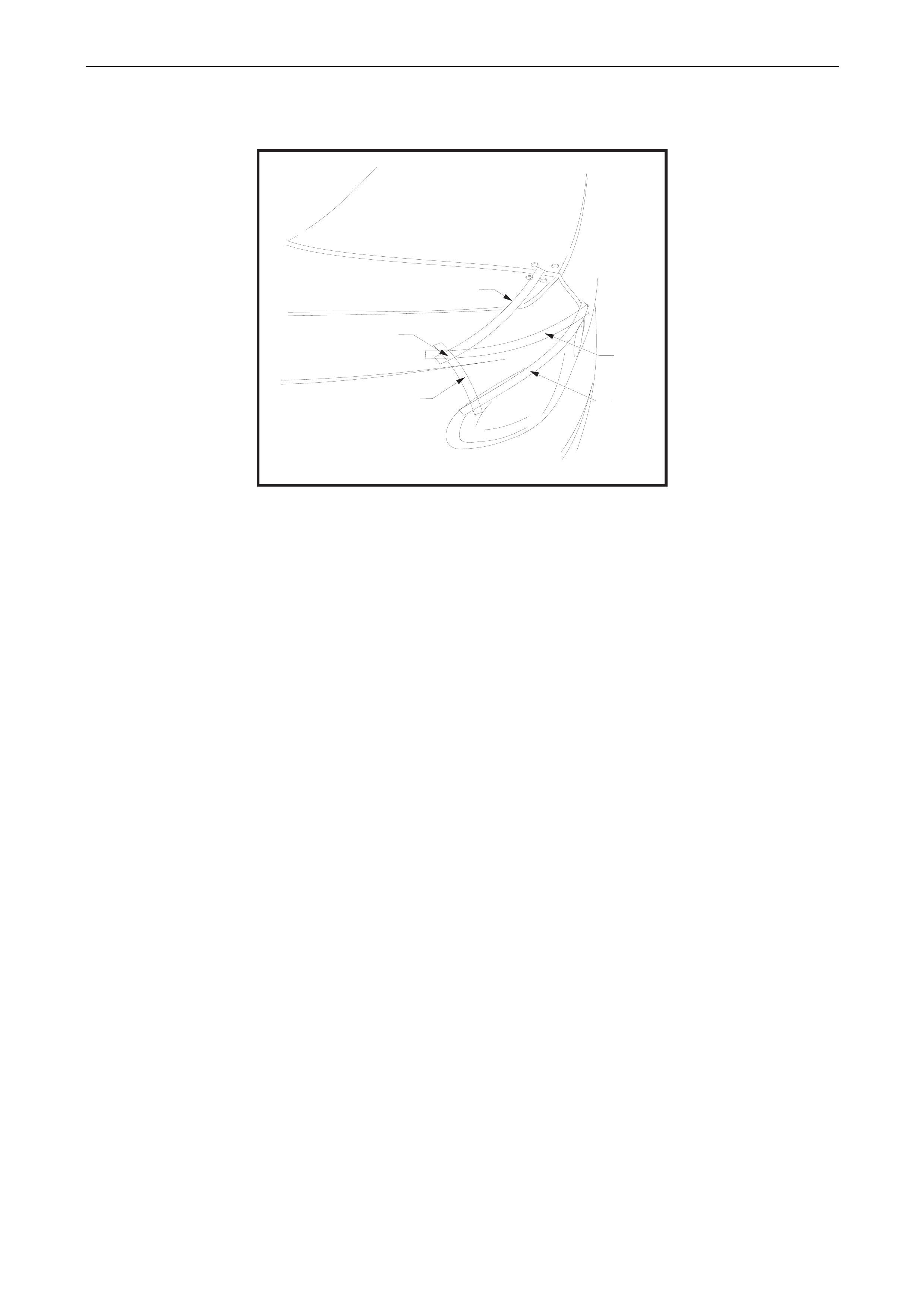
Using Strip D (100 mm distance) locate the datum mark at the point previ ously measured along the Tail Lamp upper
edge, with the strip running al ong the panel scribe a third arc onto the tape this is a confirmation of the previous arcs.
Refer Figure 8
STEP 4
FOR LOCATION IN REAR
QUARTER OUTER PANEL
OF 27.0 mm DIA SPOILER HOLE
FIG 8
STRIP A
CENTRE PUNCH AND DRILL
8.0 mm PILOT HOLE
STRIP B
STRIP C
STRIP C
Carefully centre punc h the hole position and drill 6 mm pilot hole.
Drill the pilot hole to suit the bolt on a 26,0 mm chassis punch.
Punch the hole to 26,0 mm.
De-burring and Anti-corrosion Treatment
All holes must be de-burred prior to anti-corrosion treatment.
All holes must be treated with Zink-Rich Prim er, allow primer to cure and then paint the holes car co lour automotive
touch up paint prior to final assembly.
Sealing
Once all spoiler components are in place ensure the seals cover the mounting holes.
General Precaution
Cover all components inside the rear com partment to protect against ingress of drilling swarf and dust.
All parts of the spoiler (center and sides) are to be temporarily attached to the vehicle in position with masking tape while
preliminary fitment check is completed.
Check the gaps and alignment of the 3 spoiler components at all assembly stages of this procedure.

Body Page B-50
6 Roof Spoiler
ATTENTION
Before performing any service operation or other procedure described in this section refer to Section 00
CAUTIONS AND NOTES for correct workshop practices with regard to safety and/or property damage.
6.1 Service Operations
Removal
NOTE.
The roof spoiler is adhered to both the rear
window glass and the rear of the rear outer panel
with urethane adhesive. Care must be taken not
to damage the paintwork of the vehicle when
performing this operation.
1. Apply masking tape up against the front and side edges of the roof spoiler. The tape must extend for a distance
of at least 75mm away from the edges of the spoiler. This tape is to protect the roof and the rear qu arter panels
from damage when removing the spoiler an d adhesive;
2. Slide a body filler applicator or similar stiff plastic plate between the spoiler and the body panels. Using a cutting
action like a knife break the uret hane adhesive bond. The cutting will need to be done acr oss the roof panel,
down the sides of the glass and also the glass in the centre of the spoiler. The spoiler may be pulled a way from
the panel to access the urethane, but extreme care must be taken to avoid damag e to both panels and the
paintwork.
3. Clean the excess urethane off the glass and panel work with a Profit wheel, decal removing wheel or similar
implement. Extreme care mus t be taken to avoid damage to the panels and the paintwork.
Installation
1. Remove the protective masking tape used i n the removal procedure;
2. Clean the attaching area with urethane cleaner and pr ime the contact area;
3. W ith the assistance of another person locate the spoiler centrally between the roof mouldings (at the
sides of the rear glass) and align the spoiler side notches (located towards the top of the edge of the
spoiler) with the top rear windo w glass mouldin g;
4. Using a china graph pencil (white), or similar, place alignment marks on the spoiler and the body. These
will be used for location of the spoiler on the vehicle when the adhesive is applied;
5. Place the new spoiler upside down on a protective cloth and app ly urethane adhesive al ong the front
edge, sides and central leg as shown on the drawing on page …..;
6. Locate the spoiler in position on the vehicle u s ing the previously applied location marks (china graph
pencil);
7. Take the spoiler to hold it in position while the urethane adh esive cures, ref. Drawing on page…. The
cure time for the urethane adhesive is 24 hours; it is not recommended that the tape be re moved, or the
vehicle driven in this period;
8. Remove the tape from the spoiler and the vehicle after the 24 hours cure time, and polish the area to
remove any foreign matter which may have been left by this oper ation;
Body Page B-51
Body Page B-52
7 Plastic Components
Plastic components are used throughout the vehicl e. The following chart is included to assist with the identification and
composition of common comp onents.
NOTE:
Most components are also identified with a
material code in an incons picuous place
COMPONENT CODE EXAMPLE
Exterior / Engine Compartment :
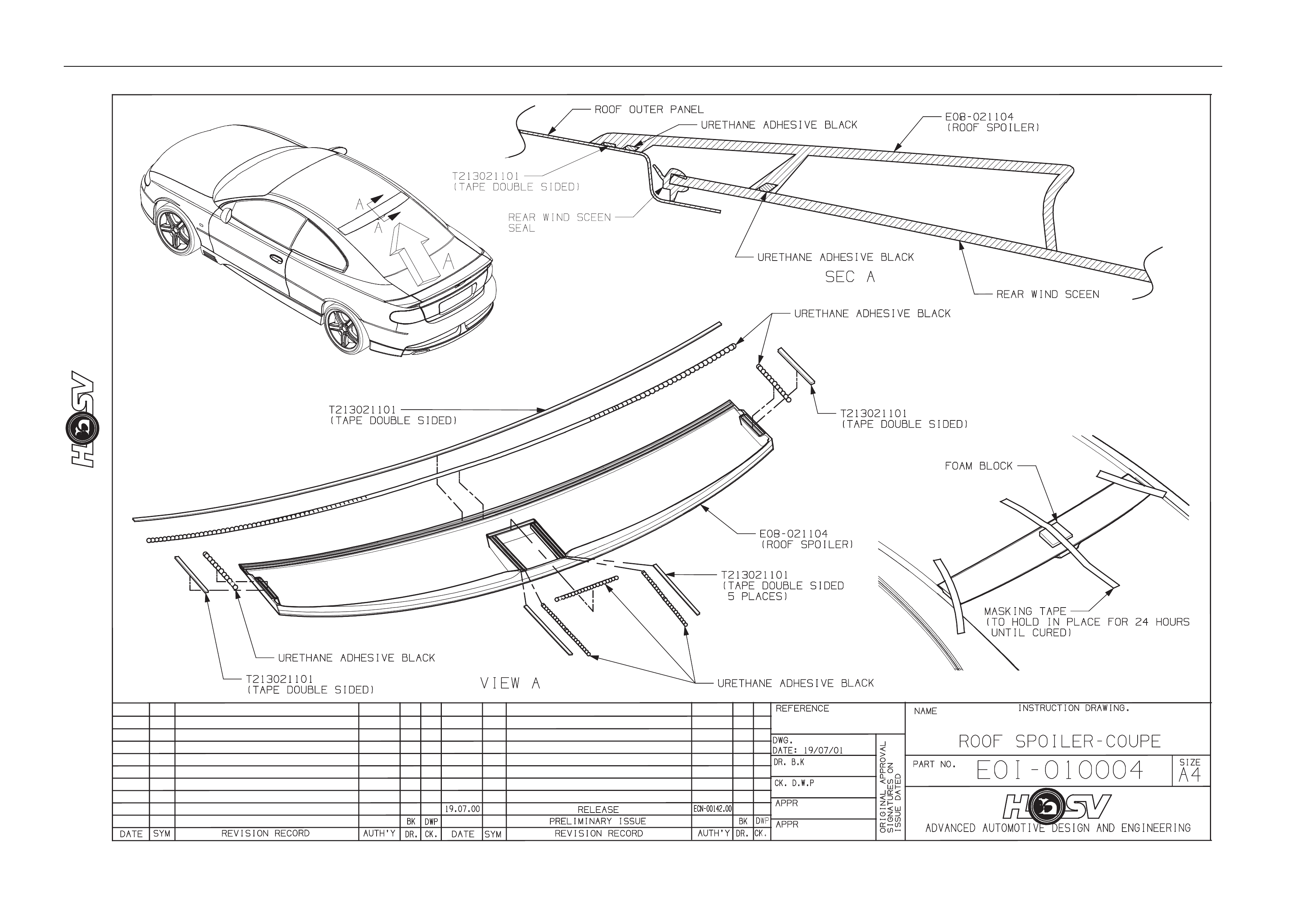
Front Bumper Facia
(Supplied Primed)
RRIM
Radiator Grille Assembly
ABS
Body Page B-53
COMPONENT CODE EXAMPLE
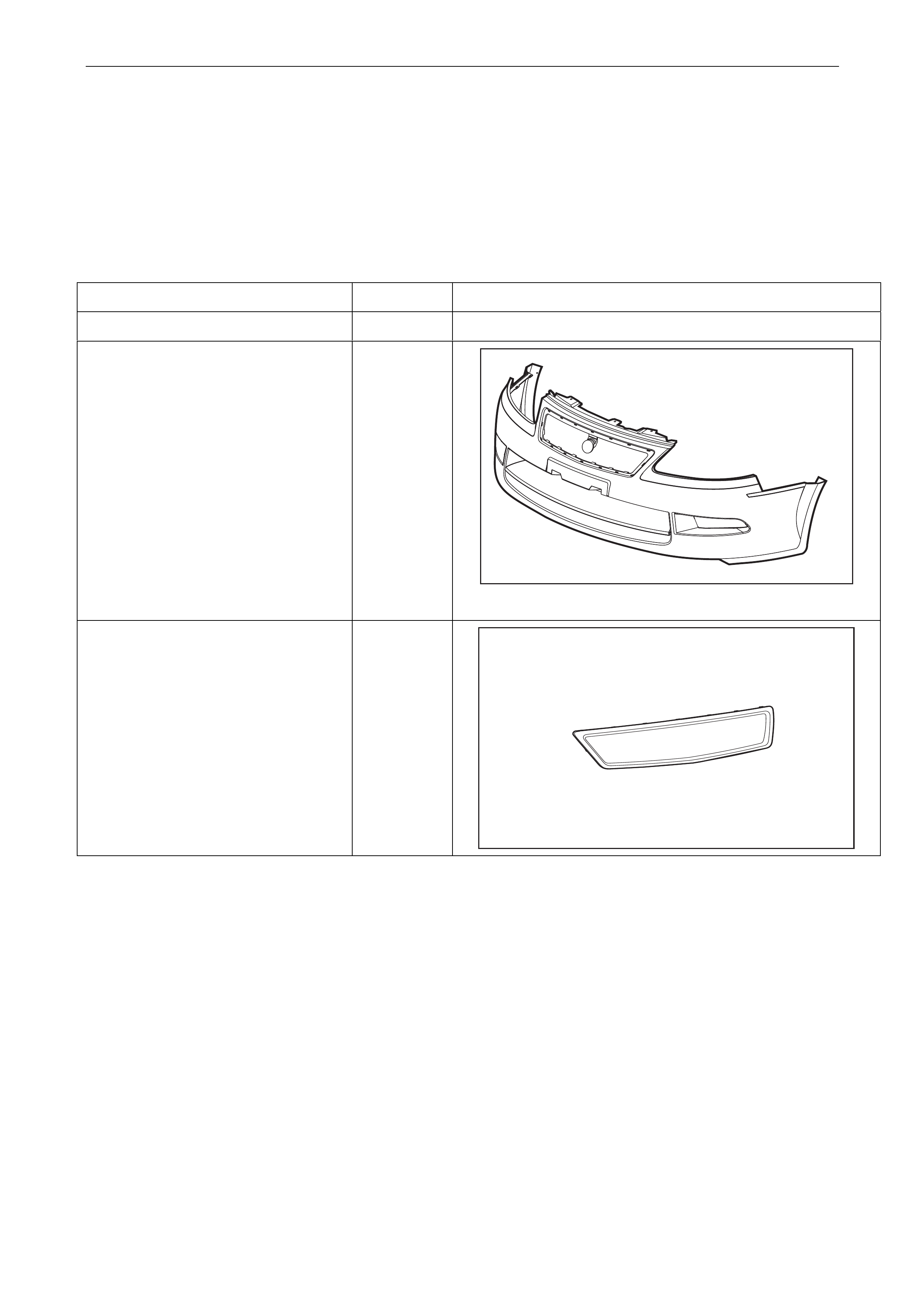
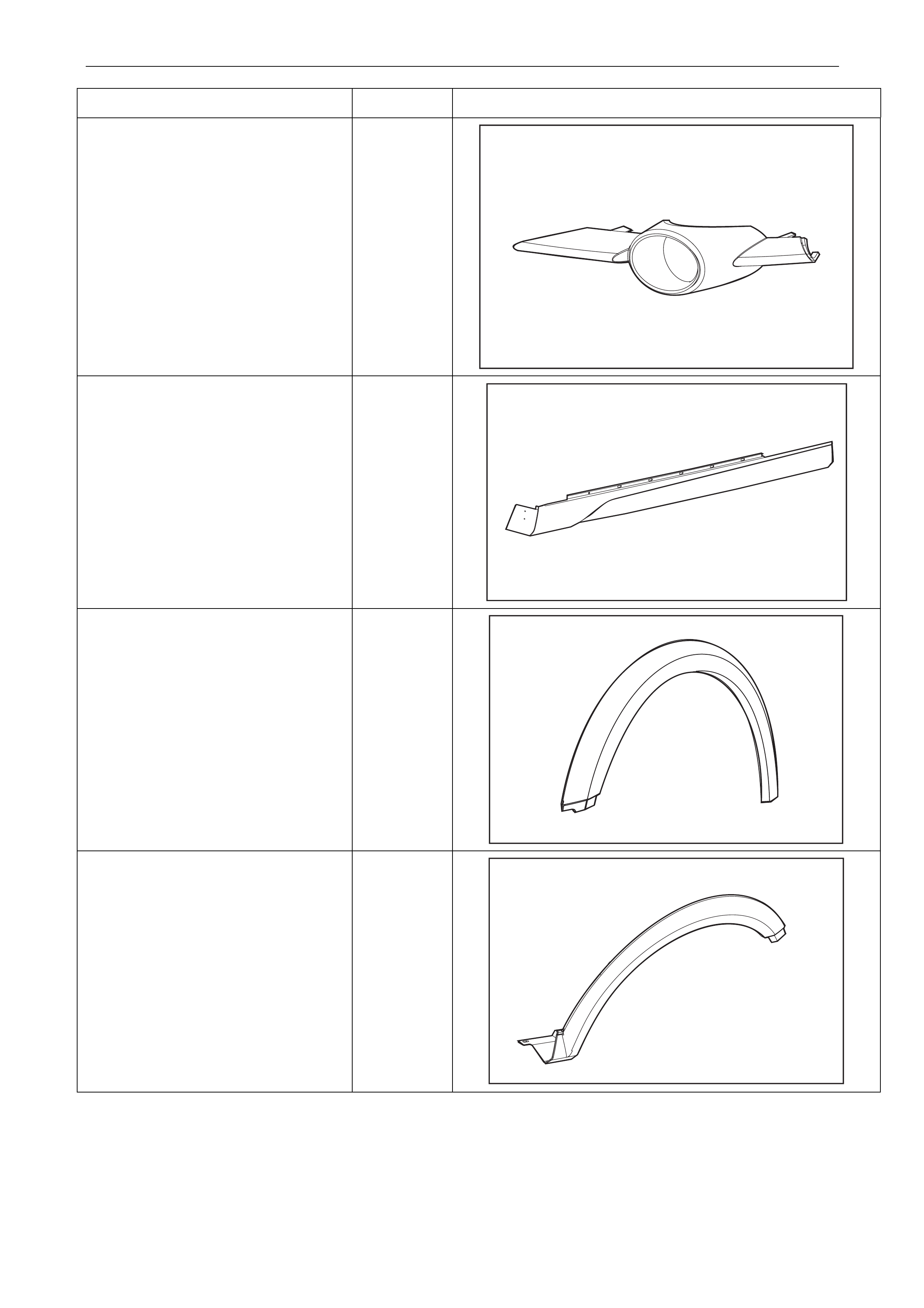
Front Fog Lamp Bezel Assem bly
ABS
Rocker Panel Moulding Assembly
(Supplied Primed)
RRIM
Front Fender Flare
(Supplied Primed)
RRIM
Rear Fender Flare
(Supplied Primed)
RRIM
Body Page B-54
COMPONENT CODE EXAMPLE
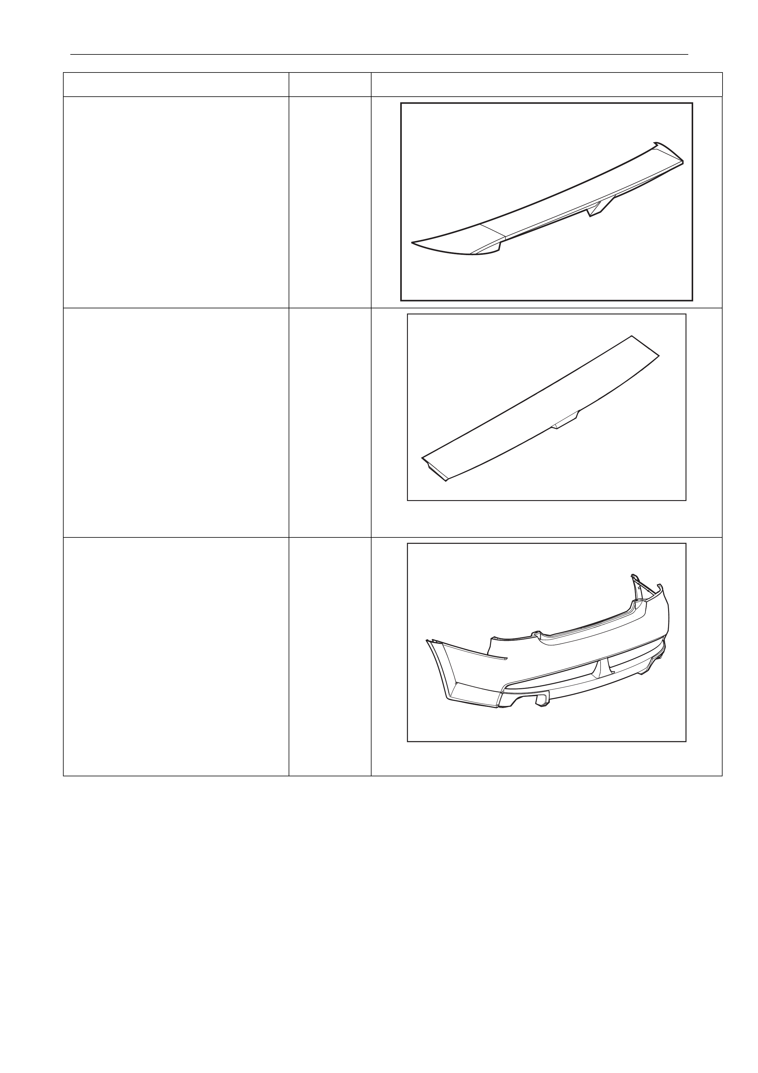
Rear Spoiler – 3 piece
(Supplied Primed)
RIDGID
URETHANE
FOAM
Roof Spoiler
(Supplied Primed)
RRIM
Rear Bumper Facia
(Supplied Primed)
RRIM

Body Page B-55
Code Material Name Heat Resisting Temp º C Resistance to
Alcohol or Gasoline
Notes
ABS
Acrylonitrile
Butadiene
Styrene Resin
80º C
Alcohol is harmless if
applied only for a short
time in small amounts
(i.e. quick wiping to
remove grease)
Avoid gasoline and
organic or aromatic
solvents.
PU
Polyurethane
Foam
100º C
Alcohol is harmless if
applied only for a short
time in small amounts
(i.e. quick wiping to
remove grease)
Avoid dipping or
immersing in alcohol,
gasoline, solvents, etc.
RRIM
Reinforced
Reaction Injected
Moulded Urethane
98º C
Alcohol is harmless if
applied only for a short
time in small amounts
(i.e. quick wiping to
remove grease)
Avoid dipping or
immersing in alcohol,
gasoline, solvents, etc.
NOTE :
The repair procedure for plastic body parts must
conform with the type of plastic material.
Temperatures higher than those listed here may
result in material distortion.

Body Page B-56
8 Front and Rear Fender Service
Instructions
The HSV Coupe 4 has unique F r ont and Rear Fenders which must be serviced with HSV service parts.
The Front and Rear Fenders have larger wheel-house openin gs than the HSV and Holden Coupes and also attaching
holes for the Fender Flares.
8.1 Front Fenders
Removal
1. The Front Fenders use the same body attachments as the Holden Coupe models.
2. Remove the Fender Liner to gain access to the fender liner attaching bolts located along the rear edge of the
Fender. Refer to the HSV Fender Liner removal procedure.
3. Remove the remaining Fender to Body attachments. Refer to the Holden MY2003 VY & V2 II Series Service
Information Section 1B Sheet Metal - 2.4 Front Fender.
Installation
1. Installation of the Front Fender is the reverse of the remov al procedure.

Body Page B-57
8.2 Rear Fenders
Removal
1. Remove the Rear Fender Liner. Refer to the HSV Fender Liner rem oval procedure.
2. The removal of the Rear Fenders is the same procedure as the Holden Coupe except for the Rear Fender W heel
House Opening. The F lange on the Opening is to be used as a Template to re-weld the Quarter Inner Panels,
Wheel House Outer Panel, and Rear Fender together.
3. Refer to the Holden MY2003 VY & V2 II Series Service Information Section 1B Sheet Metal for all other data.
Installation
1. Installation of the Rear Fender is the reverse of the removal procedure.