
Suspension Page C-1
Page C-1
Section C
Suspension
ATTENTION:
HSV vehicles are equipped with a Supplemental Restraint System (SRS). An SRS consists of seat belt pre-
tensioners (fitted to all front seats), a driver’s-side air bag , a passenger’s-side air bag and left and right hand
side air bags. Refer to CAUTIONS, Section 12M, in Volume 12M of the Holden V2 Coupe Service Manual
before performing any service operation on or around SRS components, the steering mechanism or wiring.
Failure to follow the CAUTIONS could result in personal injury or unnecessary SRS system repairs.
1 Purpose...................................................................................................................................................4
1.1 General Description............................................................................................................................................... 4
2 Wheel Alignment ....................................................................................................................................6
2.1 Steering Geometry................................................................................................................................................. 6
Caster...................................................................................................................................................................... 6
Camber ................................................................................................................................................................... 7
Wheel Toe............................................................................................................................................................... 7
Steering Axis Inclination....................................................................................................................................... 8
Scrub Radius.......................................................................................................................................................... 8
Included Angle....................................................................................................................................................... 9
Toe-Out On Turns.................................................................................................................................................. 9
2.2 Wheel Alignment Checking and Adjustment..................................................................................................... 10
Preliminary Inspection ........................................................................................................................................ 10
Caster Adjustment............................................................................................................................................... 10
Camber Adjustment............................................................................................................................................. 10
Toe Adjustment.................................................................................................................................................... 12
2.3 Jacking Precautions............................................................................................................................................ 13
2.4 Front Wheel Hub Assembly – End Float Checking Procedure ........................................................................ 14
3 Front Suspension.................................................................................................................................15
3.1 Service Notes And Cautions............................................................................................................................... 15
3.2 Front Wheel Hub Assembly and Brake Rotor.................................................................................................... 17
Remove................................................................................................................................................................. 17
Inspect .................................................................................................................................................................. 18
Reinstall................................................................................................................................................................ 19
3.3 Front Wheel Hub Studs....................................................................................................................................... 20
Replace................................................................................................................................................................. 20
3.4 Front Strut Assembly........................................................................................................................................... 22
Remove................................................................................................................................................................. 22
Reinstall................................................................................................................................................................ 24
3.5 Upper Strut Support Bearing and Mount........................................................................................................... 26
Remove................................................................................................................................................................. 26
Reinstall................................................................................................................................................................ 27
3.6 Front Spring ......................................................................................................................................................... 28
Remove................................................................................................................................................................. 28
Reinstall................................................................................................................................................................ 28
3.7 Front Strut Unit .................................................................................................................................................... 29
Replace................................................................................................................................................................. 29
3.8 Steering Knuckle.................................................................................................................................................. 30
Remove................................................................................................................................................................. 30
Reinstall................................................................................................................................................................ 33

Suspension Page C-2
Page C-2
3.9 Front Control Arm Ball Joint Assembly............................................................................................................. 35
Inspect .................................................................................................................................................................. 35
Remove................................................................................................................................................................. 35
Reinstall................................................................................................................................................................ 35
3.10 Front Control Arm................................................................................................................................................ 36
Remove................................................................................................................................................................. 36
Reinstall................................................................................................................................................................ 38
3.11 Front Control Arm Rear Bushing........................................................................................................................ 39
Replace................................................................................................................................................................. 39
3.12 Front Control Arm Front Isolating Bushing....................................................................................................... 41
Inspect .................................................................................................................................................................. 41
Replace................................................................................................................................................................. 41
3.13 Front Suspension Crossmember Cradle ........................................................................................................... 44
Remove................................................................................................................................................................. 44
Reinstall................................................................................................................................................................ 47
3.14 Stabiliser Bar Link ............................................................................................................................................... 49
Replace................................................................................................................................................................. 49
3.15 Stabiliser Bar Isolator Bushes............................................................................................................................ 51
Replace................................................................................................................................................................. 51
3.16 Stabiliser Bar........................................................................................................................................................ 52
Remove................................................................................................................................................................. 52
Reinstall................................................................................................................................................................ 53
4 Independent Rear Suspension ...........................................................................................................54
4.1 General Information............................................................................................................................................. 54
4.2 Rear Axle .............................................................................................................................................................. 55
4.3 Propeller Shaft And Universal Joints................................................................................................................. 56
4.4 Service Operations .............................................................................................................................................. 57
General ................................................................................................................................................................. 57
Rear Axle .............................................................................................................................................................. 57
Propeller Shaft And Universal Joints................................................................................................................. 57
5 Diagnosis ..............................................................................................................................................58
5.1 General ................................................................................................................................................................. 58
Strut Diagnosis .................................................................................................................................................... 58
Acceptance Criteria ............................................................................................................................................. 58
5.2 Diagnosis Guide................................................................................................................................................... 59
Hard or Heavy Steering ....................................................................................................................................... 59
Excessive Play or Looseness in Steering.......................................................................................................... 59
Erratic Steering on Application of Brakes......................................................................................................... 60
Vehicle Pulls to One Side.................................................................................................................................... 60
Front or Rear Wheel Tramp................................................................................................................................. 61
Road Shocks........................................................................................................................................................ 61
Scuffed Tyres....................................................................................................................................................... 61
Cupped Tyres....................................................................................................................................................... 62
Front Wheel Shimmy........................................................................................................................................... 62
Vehicle Wanders.................................................................................................................................................. 63

Suspension Page C-3
Page C-3
6 Front Suspension Specifications .......................................................................................................64
Suspension Travel............................................................................................................................................... 64
Front Spring Details............................................................................................................................................. 64
Front Stabiliser Bar Details................................................................................................................................. 64
Front Strut Details................................................................................................................................................ 65
Front Control Arm Details................................................................................................................................... 65
Front Control Arm Ball Joint............................................................................................................................... 65
Front Wheel Bearings.......................................................................................................................................... 65
Wheel Bearing Angular 'Float' ............................................................................................................................ 65
Suspension Trim Height Specifications ............................................................................................................ 66
Front Wheel Alignment Specifications .............................................................................................................. 67
7 Rear Suspension Specifications ........................................................................................................68
Rear Spring Detail................................................................................................................................................ 68
Rear Shock Absorber Detail................................................................................................................................ 68
Rear Stabiliser Bar Detail.................................................................................................................................... 68
Rear Suspension Service Alignment Data......................................................................................................... 68
8 Torque Specifications..........................................................................................................................69
9 Special Tools ........................................................................................................................................70
Suspension Page C-4
Page C-4
1 Purpose
The purpose of this section is to provide information on the front and rear suspension assemblies fitted to HSV Coupe 4
models. The information is designed to supplement the information contained in the Holden V2 Coupe Series Service
Manuals, and details are given where differences occur between the HSV models and standard Holden models. A series
of instruction drawings describe the design changes and indicate specific part numbers, fitting instructions and relevant
notes for vehicle servicing.
NOTE:
If specific technical data on a HSV model is not
contained in this supplement, obtain data for that
model from the relevant Holden Coupe Series 2
Service Information Supplement. References are
made throughout this section to Holden Service
Manuals, to assist in providing information for
specific service operations.
When hoisting (or jacking) HSV models,
ensure that the liftin g head of the hoist lifts on
the chassis before the arm of the hoist
contacts the side-skirt
1.1 General Description
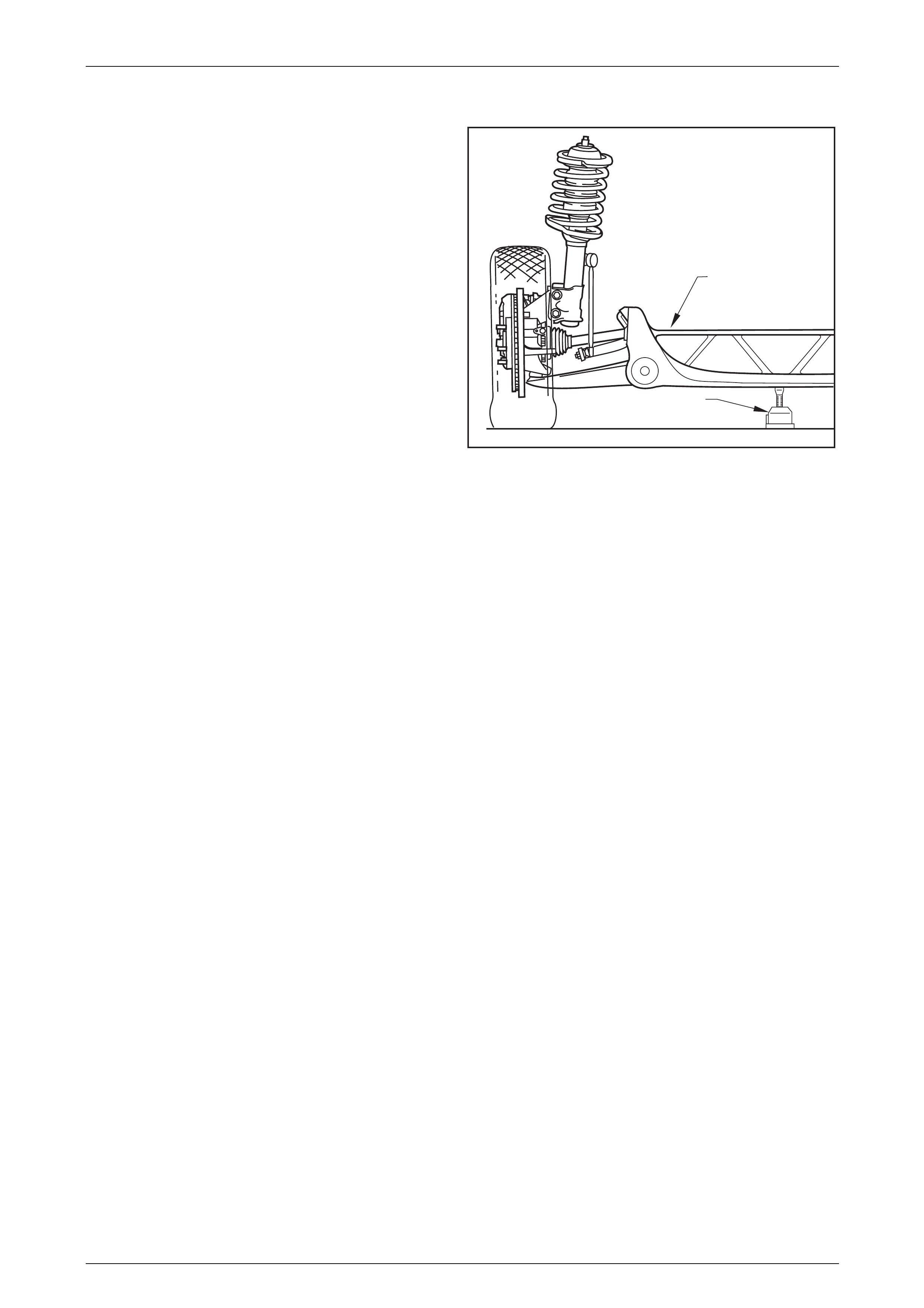
The front suspension fitted to all MY 2004 AWD Coupe 4 Models operates on the McPherson strut principle. The
assembly consists of the front suspension crossmember cradle, lower control arms, stabiliser bar and heavy duty strut
assemblies (Refer to Figure 3-1).
The front suspension crossmember cradle is bolted to both longitudinal frame side members. The front suspension
crossmember cradle to side member attaching bolts incorporate a tapered boss near the head of the front two bolts to
assist in crossmember to body alignment during assembly. The lower control arm pivots are rubber bushed at the inner
ends and are attached to the crossmember by a micro-encapsulated bolt at the front and a bolt at the rear. The outer end
of each front control arm is connected to the steering knuckle through a front control arm ball joint assembly.
The strut assembly incorporates a hydraulic wet sleeve type damper inside the strut tube, a rubber front strut dust shield
assembly with air filter and compression rubber, a coil type suspension spring mounted between the strut housing and
upper spring seat collar, a bearing assembly and an upper strut support.
The strut assembly is located at the upper end to the body structure by an upper strut support and secured by a self-
locking nut and locating disc. The lower end of the strut tube is fastened to the steering knuckle by two bolts and nuts.
A stabiliser bar is mounted to the side members of the front suspension crossmember cradle by two brackets and
insulating rubbers, and attaches to each strut tube by a socket stud and attaching nut. The lower end of the stabiliser bar
spacer stud is connected to the stabiliser bar with a socket stud and nut.
To increase body rigidity, a strut brace is attached to each strut tower by two nuts on each side. For service procedures
relating to this strut brace, refer to 1A1 Body, in the MY 2004 AWD Wagon Service Information.
Legend for Figure 3 – 1
1 Double Ball Joint Drop Link 9 Bolt (2 Places) 16 Socket stud (2 Places)
2 Flanged Nut (4 Places) 10 Front Control Arm (2 Places) 17 Bolt (6 Places)
3 Bracket (2 Places) 11 Bolt (2 Places) 18 Nut (2 Places)
4 Insulator (2 Places) 12 Bolt – Front, Flanged (2
Places)
5 Bar – Stabiliser 12a Bolt – Rear, Plain (2 Places)
6 Nut (4 Places) 13 Cover – Dust (2 Places)
7 Driveshaft - Front (2 Places) 14 Nut (2 Places)
8 Front Suspension
Crossmember Cradle 15 Locating Disc (2 Places)
Fasteners must be new and assembled dry.
Suspension Page C-5
Page C-5
AWD3001
B
B
A
1
2
3
4
5
6
7
8
9
A
10
11
12
13
14
15
16
17
18
12a
Figure 3 – 1
Suspension Page C-6
Page C-6
2 Wheel Alignment
ATTENTION:
All front suspension fasteners are important attaching parts as they affect the performance of vital
components and/or could result in major repair expense. Where specified in this section, fasteners MUST be
replaced with parts of the same part number or an approved equivalent. Do not use fasteners of an inferior
quality or substitute design.
Torque values must be used as specified during reassembly to ensure proper retention of all suspension
components.
Throughout this section, fastener torque wrench specifications may be accompanied with the following
identification marks:
Fasteners must be replaced after loosening.
Vehicle must be at curb height before final tightening.
Fasteners either have micro encapsulated sealant app lied o r incorpo rate a mechanical thread lock and
should only be re-used once. If in doubt, replacement is recommended.
If one of these identification marks is present alongside a fastener torque wrench specification, the
recommendation regarding that fastener must be adhered to.
2.1 Steering Geometry
To achieve the desired handling characteristics of a vehicle under various operating conditions, modern steering
geometry relates to both front and rear suspension systems. It must also be realised that the various, measurable angles
that can be checked while the vehicle is stationary, are no real indication of the changes that occur in a dynamic situation,
when the vehicle is required to have directional stability, during normal manoeuvres, such as straight ahead driving,
cornering or braking.
Even though some of the following descriptions of front wheel alignment angles are not normally measurable and (in
some instances) not adjustable, each is an inherent part of the vehicle's dynamic suspension tuning that has been
developed over an extended testing program.
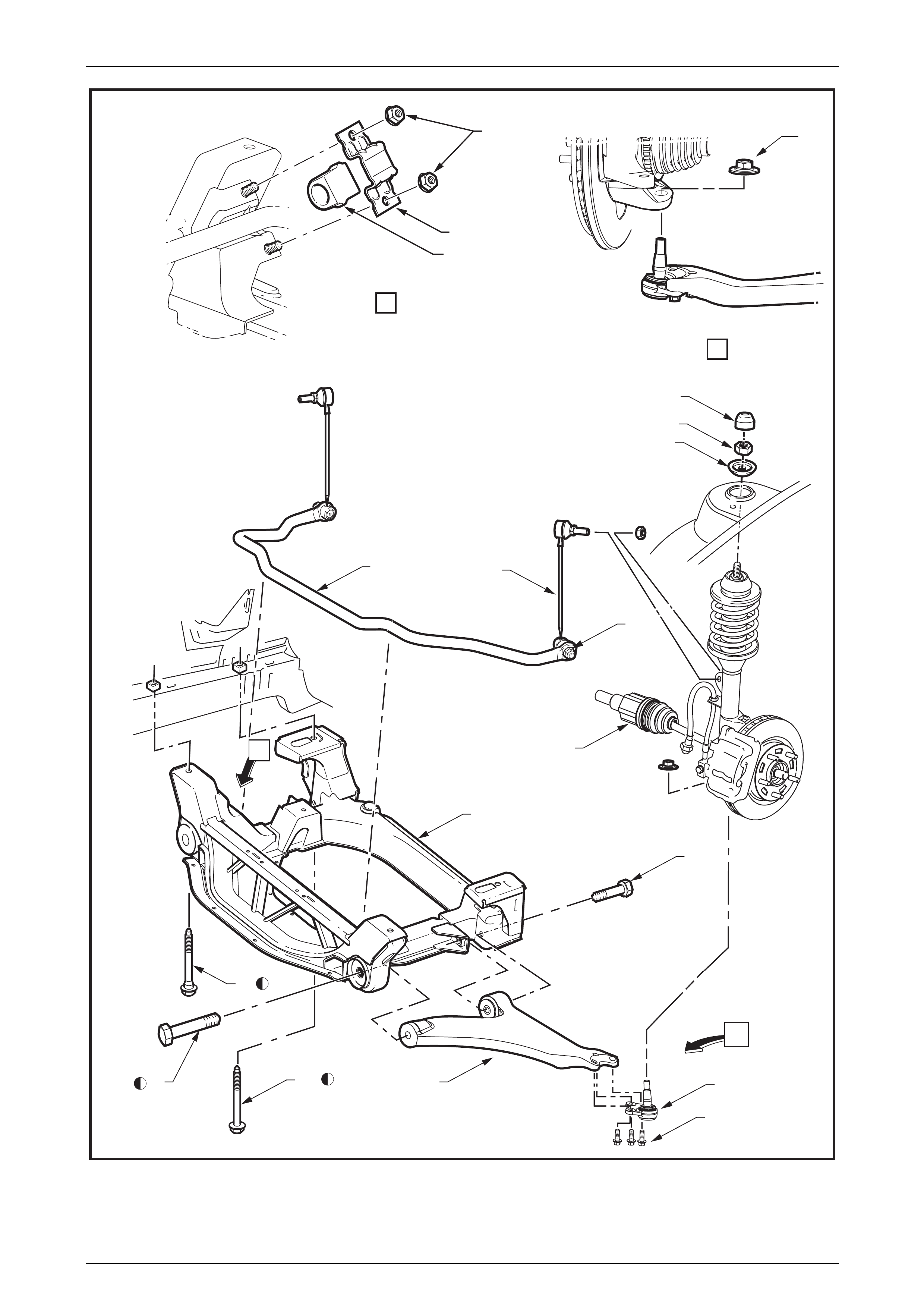
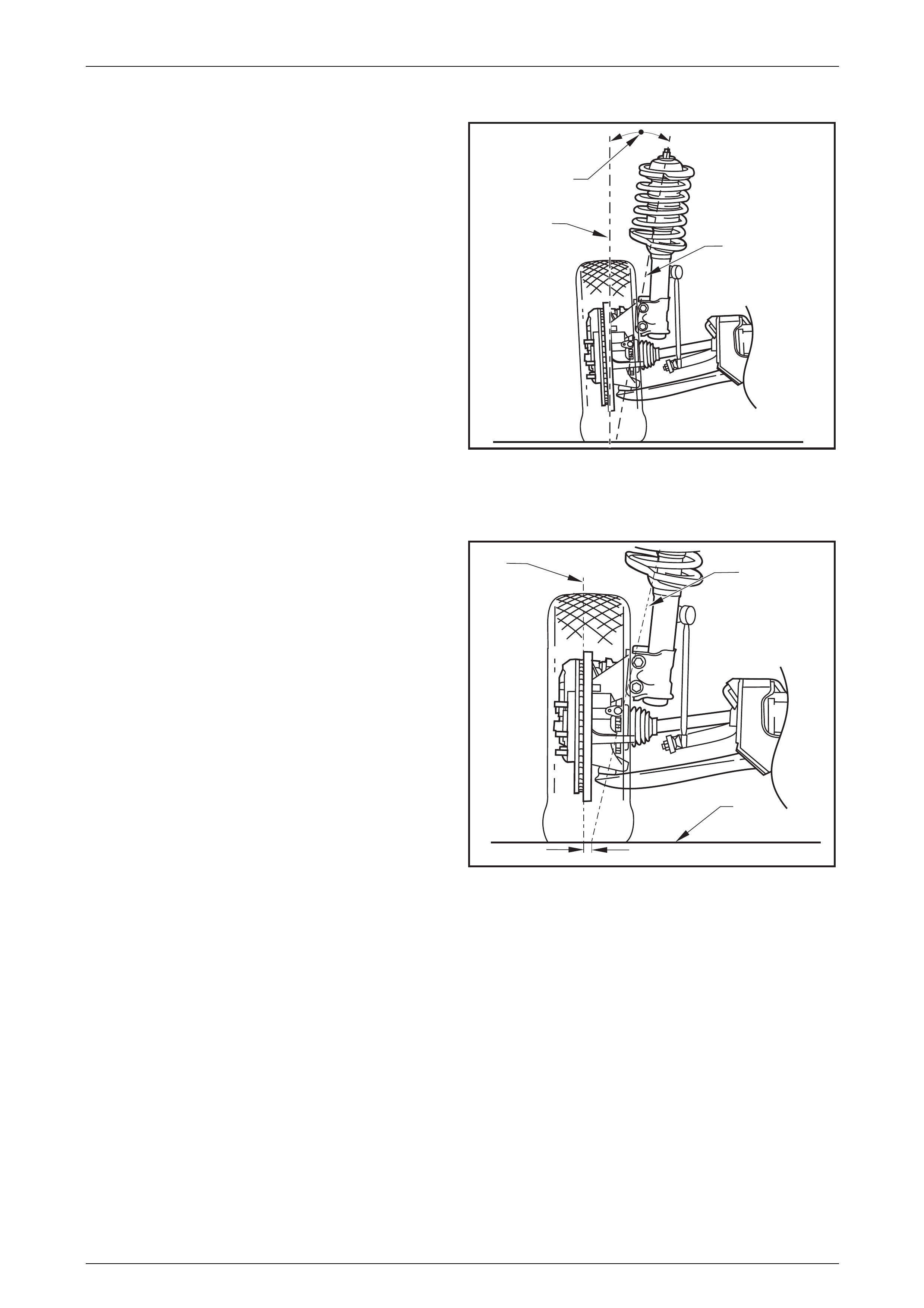
Caster
It is usual to describe this front wheel alignment angle as the
tilting of the steering axis either forward or backward (1)
from the vertical (2) when viewed from the side of the
vehicle. A backward tilt at the top steering axis point is said
be positive (+) and a forward tilt is said to be negative (–).
Measurement is usually expressed as an angle in degrees
and minutes. Figure 3-2 shows the usual practice where the
vertical and steering axis centrelines both pass through the
wheel centre (3).
This results in a caster trail (4), which can be described as
being the distance in side view, between the point where the
steering axis contacts the ground and the centre of the tyre’s
footprint contact.
Figure 3 – 2
Suspension Page C-7
Page C-7
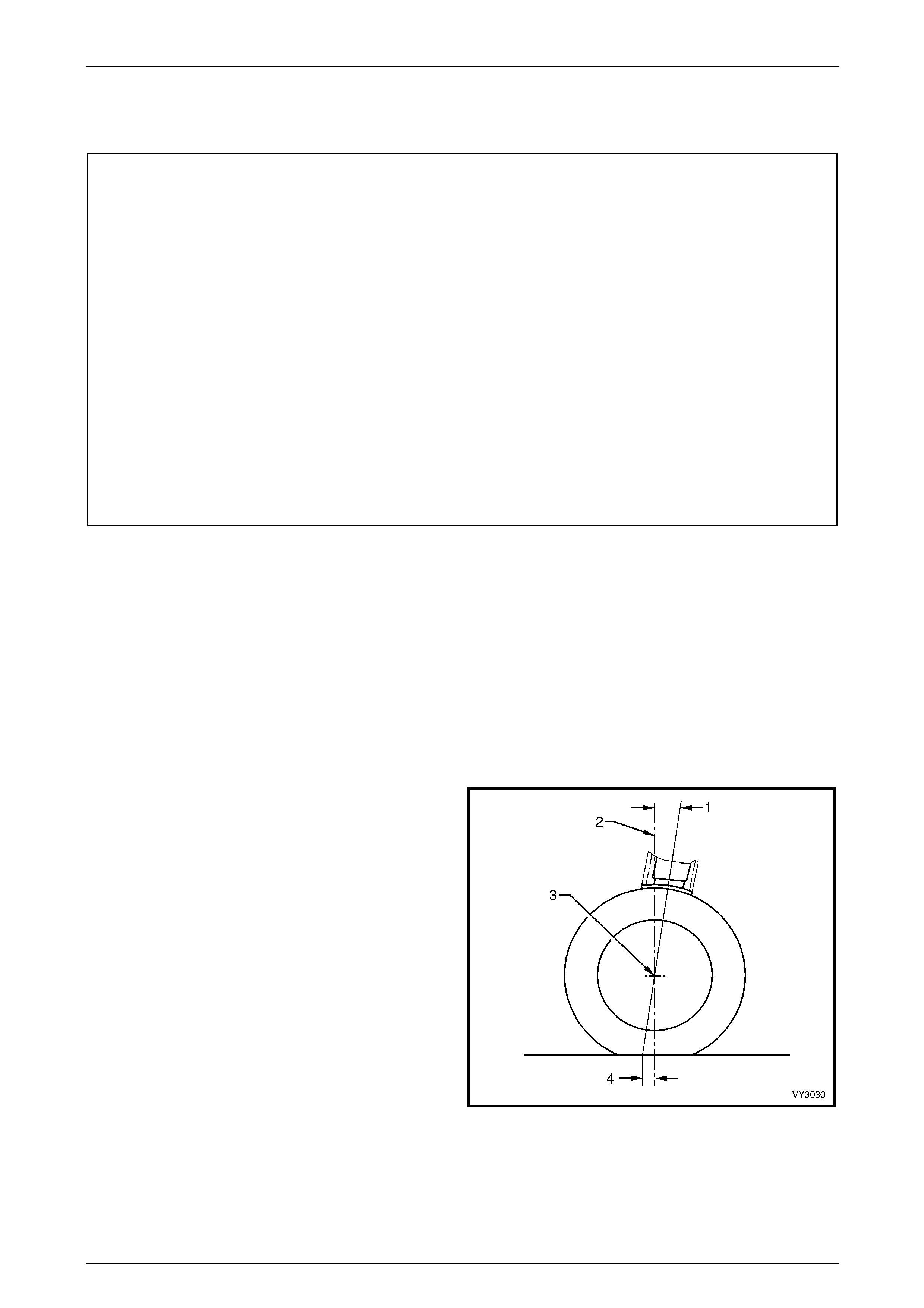
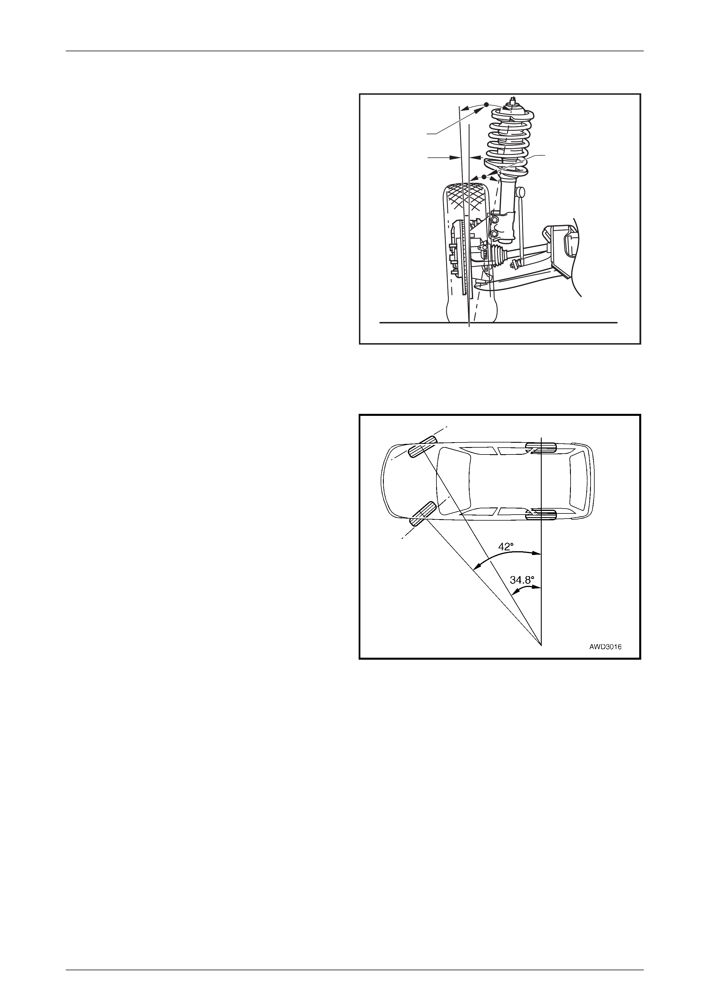
The amount of caster angle (1) will determine the ability of
the steering to return to the straight ahead position after a
cornering manoeuvre. Too high an angle though, can result
in an excessive steering effort with associated ‘wheel fight'
and ‘kickback'. To optimise vehicle handling and control
during cornering and to maintain the benefits of positive
caster, MY 2004 Coupe 4 models have a spindle offset (2)
incorporated into the suspension design.
This is achieved by moving the wheel spindle centreline (3)
forward, which will effectively reduce the caster trail by the
same amount (Refer to Figure 3-3). This action reduces the
undesirable effects of a high caster angle but maintains the
directional stability, increased front axle lateral grip and
steering feel that a high caster angle normally provides.
2
1
3
Figure 3 – 3
Camber
This angle is the tilting of the wheels from the vertical (1)
when viewed from the front of the vehicle. When the wheels
tilt outward at the top, the camber (2) is said to be positive
(+). When the wheels tilt inward at the top, camber is said to
be negative (–). The amount of tilt is measured in degrees
from the vertical and this measurement is called the camber
angle.
While unequal camber may result in unstable steering or
wander, unequal and/or excessive camber can also cause
rapid tyre wear.
2
1
Figure 3 – 4
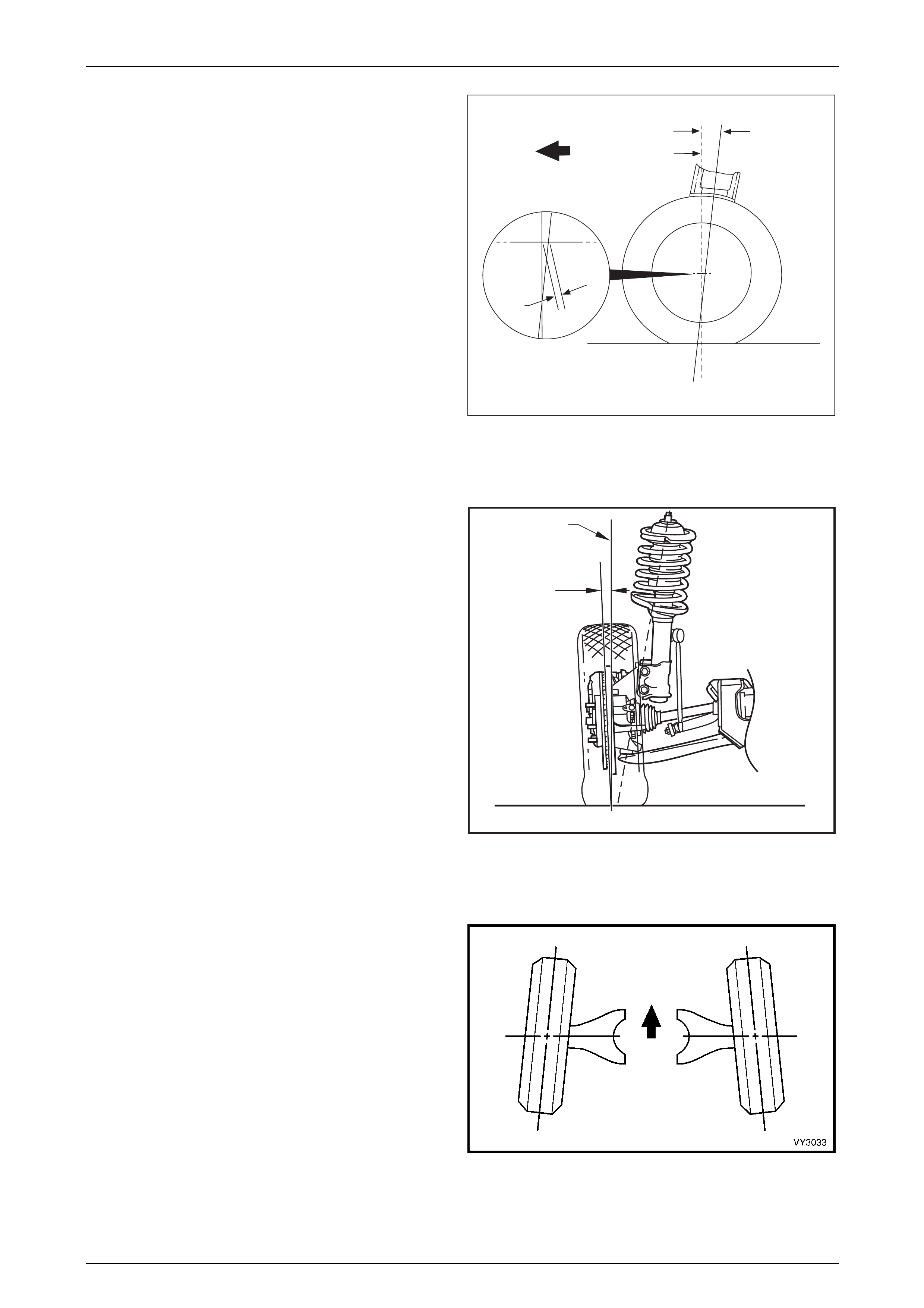
Wheel Toe
Wheel Toe (Refer to Figure 3-5), is the turning in (or out) of
the wheels when viewed from the overhead position. The
actual amount of toe is normally only a few minutes of one
degree. The purpose of a static toe specification is to ensure
parallel rolling of the wheels, once the vehicle is in a
dynamic state.
Excessive toe-in or toe-out may increase tyre wear. With
rear wheel drive vehicles, a slight amount of toe-in,
measured statically with the vehicle at rest, is required to off-
set the small deflections due to rolling resistance and brake
applications which tend to turn the wheels outward, when
the vehicle is in motion.
Figure 3 – 5
Suspension Page C-8
Page C-8
Steering Axis Inclination
When viewed from the vehicle front, Steering Axis Inclination
(1) can be described as being the angle formed between the
steering axis (2) and the true vertical (3), where the steering
axis is the imaginary centreline through the upper strut
support bearing and the lower control arm ball joint
assembly, both components being the pivot points of the
strut assembly.
The Steering Axis Inclination angle is an important factor in
determining steering effort and directional stability of the
vehicle, by assisting caster in keeping the front wheels in a
central position. Steering Axis Inclination also provides a
self-centring effect after cornering.
While not an adjustable angle, the steering axis inclination
on the MY 2004 AWD Coupe 4, is 16.6 degrees.
2
3
1
Figure 3 – 6
Scrub Radius
This term refers to the distance (4) that two imaginary points
are apart, at the road surface (1). These two imaginary
points are;
a. The intersection of the steering axis (2) and the road
surface (1).
b. The centreline of the tyre (3) at the road surface (1).
As road wheel offset will affect scrub radius (4), in the
interests of vehicle handling and safety, non-standard road
wheels are not to be fitted to any MY 2004 AWD Coupe 4
vehicle.
MY 2004 AWD Coupe 4 is designed with a negative scrub
figure to promote stability under acceleration.
2
3
1
4
C
L
Figure 3 – 7
Suspension Page C-9
Page C-9
Included Angle
When both the Steering Axis Inclination angle (1) and
Camber angle (3) are combined, the resulting angle is
referred to as the Included Angle (2). This information can
be effectively used to determine if a component is damaged
or whether an adjustment is responsible for an out-of-
specification condition occurring.
While Figure 3-8 shows a positive camber angle, this has
only been used to clarify the term ‘Included Angle'.
2
31
Figure 3 – 8
Toe-Out On Turns
During cornering operations, a vehicle's road wheels all turn
about a common turning point, causing the outer wheels to
try and turn through a greater radius than the inner. To
overcome the tendency for wheel slip when cornering, the
outer wheel is commonly caused to toe-out, to compensate
for this increased turning circle.
The amount of toe-out during cornering, is governed by the
angle of the steering arms, which are an inherent part of the
steering knuckle.
Figure 3 – 9

Suspension Page C-10
Page C-10
2.2 Wheel Alignment Checking and
Adjustment
LT Section No. – 06-212
ATTENTION
The following fasteners MUST be replaced when p erfo rmin g these operations:
Steering knuckle to strut attaching bolts and nuts.
Preliminary Inspection
Before any attempt is made to check camber, caster or toe-in, these preliminary checks should be carried out.
1 Check tyre and tyre mountings. Always check camber and toe-in at the mean run-out position on the tyre or rim.
2 Check and adjust tyre pressures to recommended values.
3 Front wheel bearing end float is to be checked to ensure it is within specification, refer to
2.4 Front Wheel Hub Assembly – End Float Checking Procedure, in this Section.
4 Front lower control arm socket assembly and pivot bushing should be checked for wear, refer to
3.9 Front Control Arm Ball Joint Assembly, in this Section.
5 Check steering gear mounting bolts for tightness and steering linkage outer tie rod sockets for wear, refer to
Section 9 Steering in the MY 2004 AWD Wagon Service Information, for the procedures.
6 The vehicle should be at curb weight, fuel tank full, without driver, passengers or luggage etc.
7 Check for improperly operating front struts or rear shock absorbers.
8 Check for loose or missing stabiliser bar or spacer stud to strut tube attachments.
9 Before checking the front wheel alignment, refer to 2.7 Rear Wheel Alignment Checking in
Section 4A Rear Suspension in the MY 2004 AWD Wagon Service Information, for wheel alignment details.
Caster Adjustment
No provision for caster adjustment is provided with the front suspension design utilised for the MY2004 Coupe 4 series of
vehicles.
Camber Adjustment
1 Raise the front of the vehicle and support on safety stands under the front side members.
Refer to 2.3 Jacking Precautions in this Section.
2 Mark the relationship of the wheel to the hub stud, using a felt tipped pen or similar.
3 Loosen, then remove the road wheel attaching nuts, working in a 'star' pattern.
Refer to Section 10, Wheels and Tyres, in the MY 2003 VY and V2 Series Service Information, for detailed
information. Remove the road wheel.
NOTE
Steps 2 and 3 are necessary to maintain
component relationships and to avoid brake rotor
distortion and the creation of brake shudder, after
the vehicle is placed back in service.
Suspension Page C-11
Page C-11
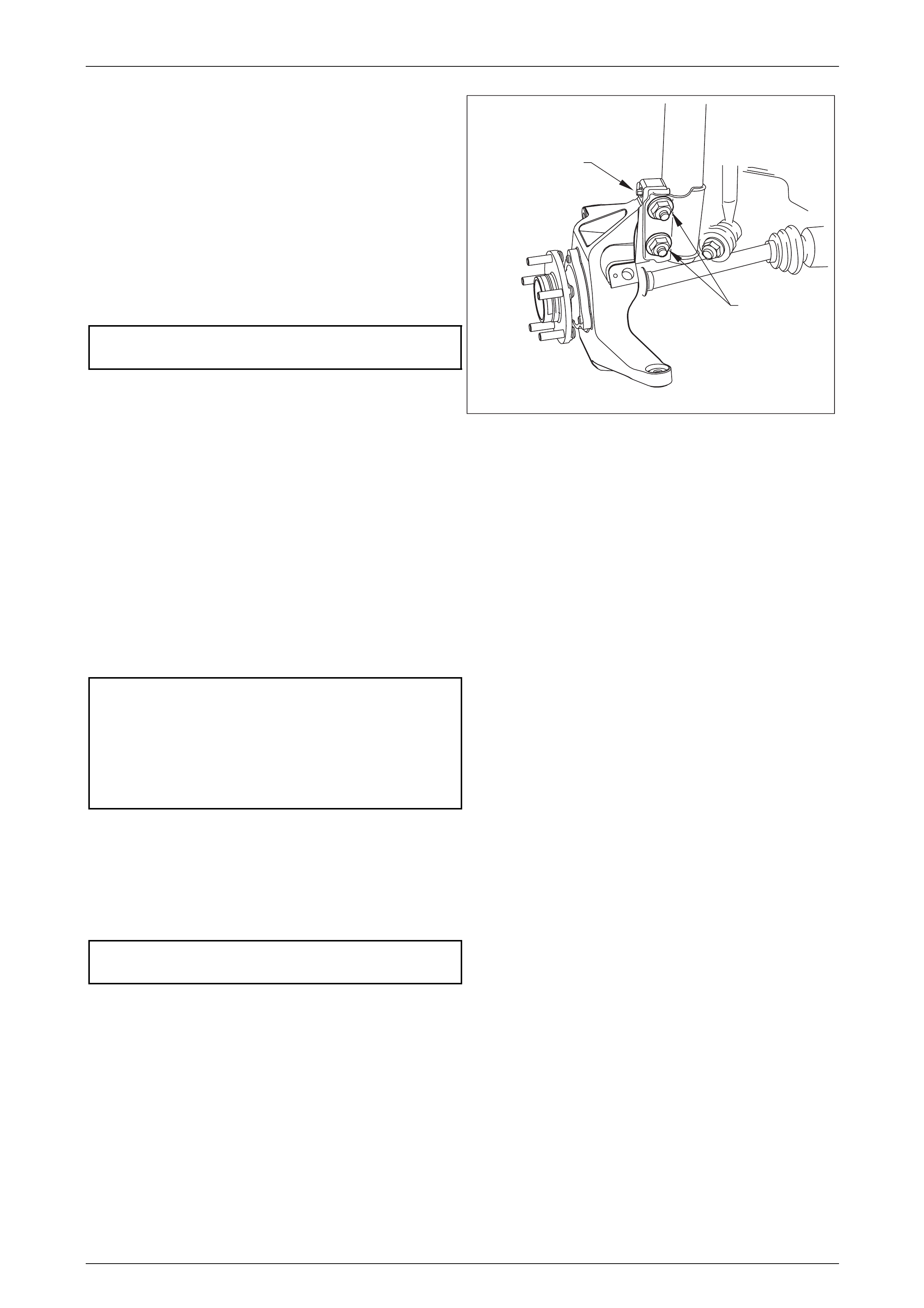
4 Loosen, remove and discard the two lower strut
attaching bolts and nuts (1).
Install NEW lower strut attaching bolts and nuts but do
not tighten fully to specification until after the camber
has been adjusted to the recommended specification.
5 Reinstall the road wheel, aligning the previously made
marks. Tighten the road wheel attaching nuts to
correct torque specification, working in a ‘star’ pattern.
Refer to Section 10 Wheels and Tyres, in the MY 2003
VY and V2 Series Service Information, for detailed
information regarding installation procedure for the
road wheels.
Road wheel attaching nut
torque specification............................................125 N.m
6 Lower the vehicle to the ground and bounce several
times to settle the suspension, then check the camber
angle.
1
2
Figure 3 – 10
7 If required, adjust the camber by turning the camber adjusting screw ('2' in Figure 3-10) in the required direction;
clockwise to reduce negative camber, anti-clockwise to reduce positive camber.
NOTE
The camber adjusting screw has thread sealant
applied in the form of micro-encapsulation and
does not require a lock nut.
8 Raise vehicle once again, support on safety stands and remove the front road wheels.
9 Tighten both steering knuckle attaching nuts to the correct torque specification.
( ) Steering knuckle to strut
attaching nut torque specification
Stage 1 ................................................................85 N.m
Stage 2 ..............................................................100 N.m
Stage 3 ............................................... Turn through 90 °
10 Install the road wheels, aligning the marks made prior to removal.
11 Remove the jack stands and lower the vehicle.
12 Tighten the road wheel attaching nuts to the correct torque specification, working in a ‘star’ pattern.
Refer to Section 10 Wheels and Tyres, in the MY 2003 VY and V2 Series Service Information, for detailed
information regarding installation procedure for the road wheels.
Road wheel attaching nut
torque specification............................................125 N.m
13 Install the decorative centre wheel cap.
14 Check the camber angle again to ensure that it is still within specification.
Suspension Page C-12
Page C-12
Toe Adjustment
Toe of both front wheels, is checked with the wheels in the
straight ahead position.
Adjustment is achieved by winding the steering linkage inner
tie rod into or out from the outer tie end, thus increasing or
decreasing the linkage length and thereby altering the toe-in
setting.
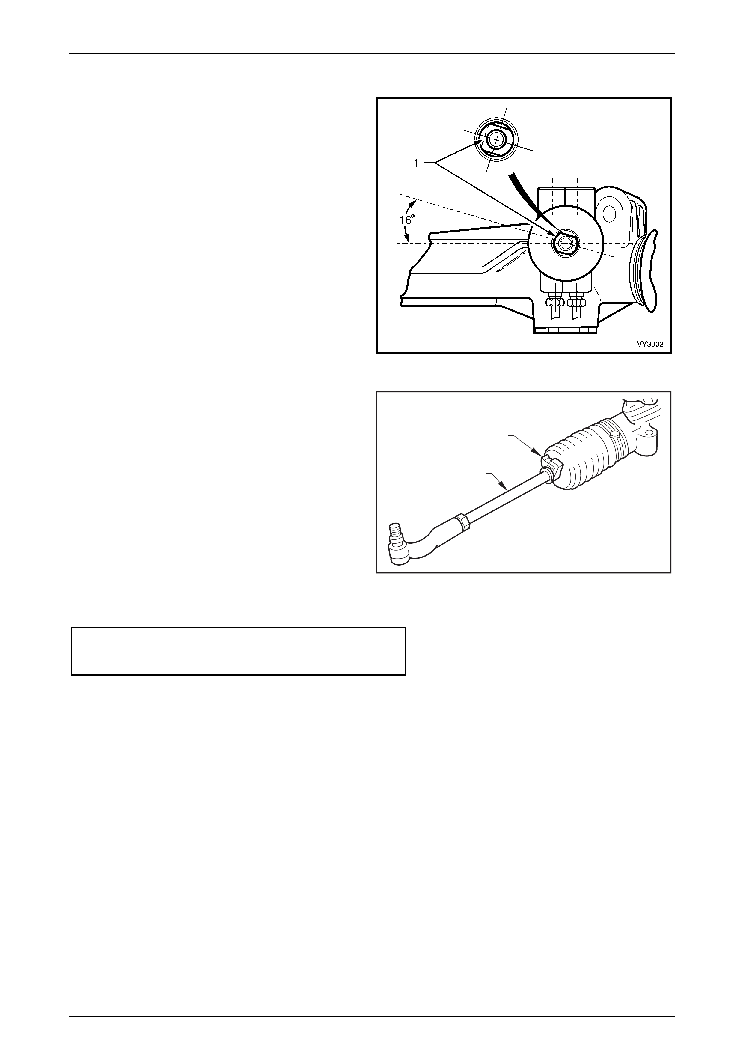
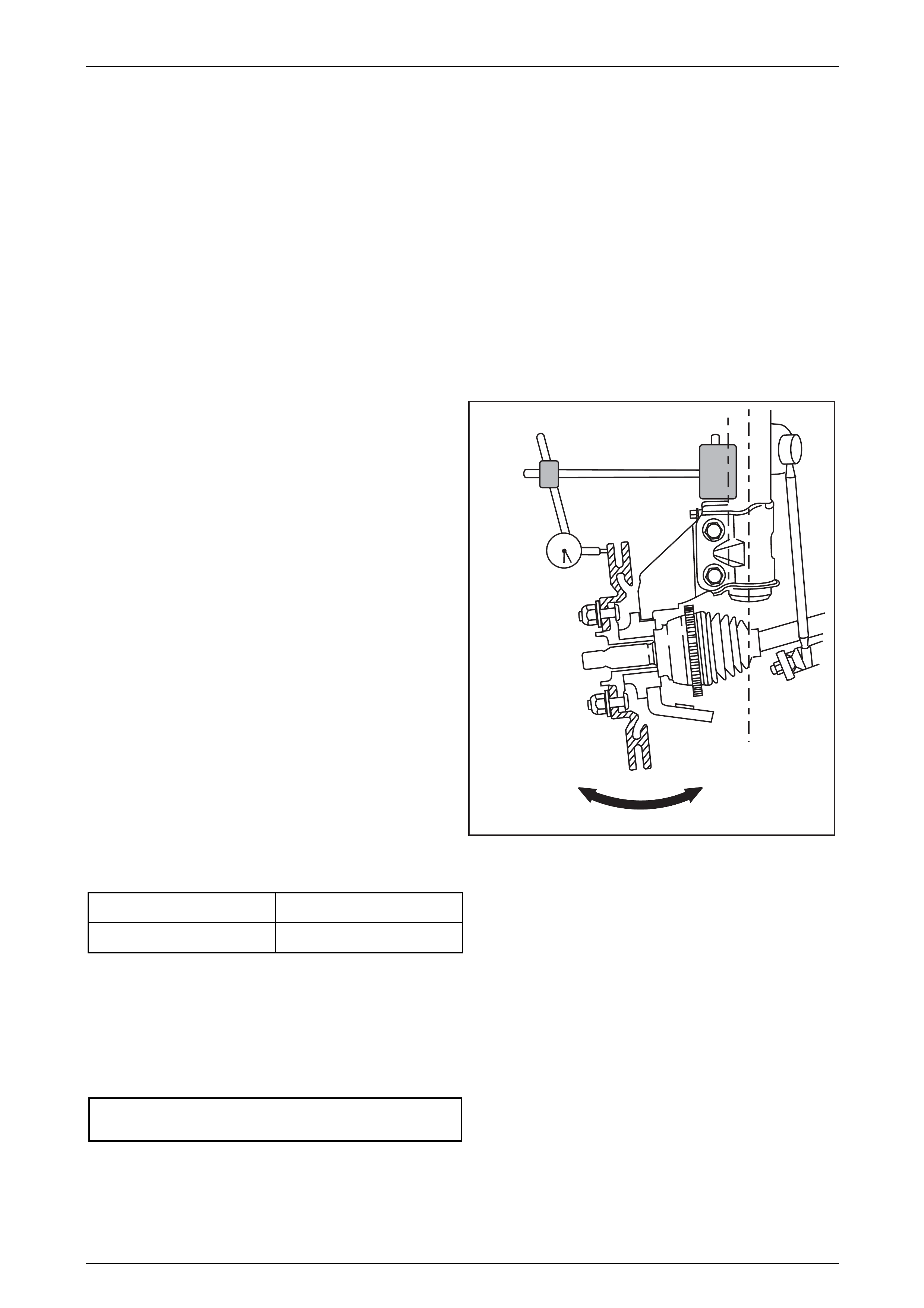
1 Set steering gear and wheels in straight ahead
position.
2 To check if steering gear is in straight ahead position
(on-centre), the pinion (input) shaft (1) should be
aligned as shown.
Figure 3 – 11
3 Before adjusting the steering linkage inner tie rods (1),
disconnect the steering gear outer boot clips (2).
4 Loosen the lock nut (3) at the end of each steering
linkage outer tie rod end.
5 Turn each steering linkage inner tie rod as required,
until the correct toe is obtained.
NOTE
During the toe adjustment, ensure that the
steering wheel is held in the straight ahead
position.
6 Tighten the lock nuts to the correct torque
specification, ensuring that the steering linkage outer
tie rod ends are in alignment with their ball studs.
1
2
Figure 3 – 12
Steering linkage tie rod to outer
tie rod end lock nut torque
specification………………………65 N.m
7 Tighten the outer boot clips securely, making sure that the convolutions of the boots are not distorted.
8 With the steering gear in the straight ahead position, ensure that the steering wheel is centralised. If not, remove
and reposition the steering wheel, refer to Section 9 Steering, in the MY 2003 VY and V2 Series Service
Information.
Suspension Page C-13
Page C-13
2.3 Jacking Precautions
When raising the front of the vehicle with a jack (1), the jack
should be placed under the centre of the front suspension
crossmember cradle (2). THE WEIGHT OF THE VEHICLE
MUST NOT BE LIFTED UNDER THE CONTROL ARMS.
When the vehicle is raised on the jack, it must be firmly
supported on safety stands located under the frame side
members before any work is attempted. If a vehicle is not
correctly supported by safety stands, serious injury can
result if the vehicle should slip off the jack.
For further information relating to the location of jacking and
support points, refer to Section 0A General Information, in
the MY 2003 VY and V2 Series Service Information.
2
1
Figure 3 – 13
Suspension Page C-14
Page C-14
2.4 Front Wheel Hub Assembly – End Float
Checking Procedure
LT Section No. – 06-212
1 Raise the front of the vehicle and place on safety stands. Refer to 2.3 Jacking Precautions in this Section.
2 Remove the decorative wheel nut caps.
3 Loosen, then remove the road wheel attaching nuts, working in a 'star' pattern.
Refer to Section 10, Wheels and Tyres, in the MY 2003 VY and V2 Series Service Information, for detailed
information. Remove the road wheel. NOTE
Steps 2 and 3 are necessary to maintain
component relationships and to avoid brake rotor
distortion and the creation of brake shudder, after
the vehicle is placed back in service.
4 Temporarily install three, reversed wheel nuts with a
flat washer under each nut, to prevent damage to the
nut thread.
5 Mount a dial indicator on to a suitable magnetic stand
and attach to the front strut tube. Position the dial
indicator pointer at the outer diameter of the rotor, as
shown. NOTE
The dial indicator gauge must be mounted at
right-angles (90°) to the brake rotor friction
surface.
6 Apply an outward, 10 kg force to the outer brake rotor
diameter, in an opposite position (180°) to the dial
indicator. To maintain consistency, a spring balance
capable of measuring this force, MUST be used. With
the force applied, zero the dial indicator.
7 Apply an inward, 10 kg force to the outer brake rotor
diameter and note the dial indicator reading.
8 The reading obtained is the angular movement (not to
be confused as end float). To determine the bearing’s
serviceability, compare the measured result with the
following specifications.
Figure 3 – 14
Wheel Bearing Angular ‘Float’ Specification
New Bearing 0.106 mm Maximum
Used Bearing 0.213 mm Maximum
9 Should this inspection show that the wheel bearing assembly is outside the specified, angular ‘float’ dimension, then
the hub must be replaced. Refer to 3.2 Front Wheel Hub Assembly Brake Rotor in this Section.
10 Remove the dial indicator and stand, and the three wheel nuts and flat washers.
11 Install the road wheel, aligning the marks made prior to removal and secure with attaching nuts.
12 Raise the vehicle, remove the safety stands and lower vehicle to the ground. Tighten road wheel attaching nuts to
correct torque specification, working in a ‘star’ pattern. Refer to Section 10, Wheels and Tyres in the MY 2003 VY
and V2 Series Service Information, for detailed information regarding the installation procedure for the road wheels.
Road wheel attaching nut
torque specification………………125 N.m
13 Reinstall the decorative wheel nut caps.
Suspension Page C-15
Page C-15
3 Front Suspension
ATTENTION
All fasteners are important attaching parts as they affect the performance of vital components and/or could
result in major repair expense. Where specified in this section, fasteners MUST be replaced with parts of the
same part number or an approved equivalent. Do not use fasteners of an inferior quality or substitute design.
Torque values must be used as specified during reassembly or reinstallation of all components to ensure
correct retention.
Throughout this section, fastener torque w rench specifications may be accompanied with the follow ing
identification marks:
Fasteners must be replaced after loosening.
Vehicle must be at curb height before final tightening.
Fasteners either have micro encapsulated sealant applied o r incorporate a mechanical thread lock an d
should only be re-used once. If in doubt, replacement is recommended.
If one of these identification marks is present alongside a fastener torque wrench specification, the
recommendation regarding that fastener must be adhered to.
3.1 Service Notes And Cautions
CAUTION
Whenever any component that forms part of the ABS (if fitted) is disturbed during Service Operations, it is vital that the
complete ABS system be checked, using the procedure as detailed in the MY2004 AWD Wagon Service Information,
Section 5B ABS & TCS Function Check.
NOTE
Whenever a road wheel and/or brake disc is removed from or installed to a MY2004 AWD Coupe 4 vehicle, it MUST be
done in accordance with the procedure provided in the MY2003 VY Series and V2 Series Service Information,
Section 10 Wheel - Removal And Reinstallation.
NOTE
To ensure proper retention of the control arm, the
ball joint stud and the corresponding tapered hole
in the control arm must be cleaned of dirt and
foreign matter prior to reinstallation. Refer to 6
Front Suspension Specifications –
Suspension Trim Height Specifications
Good judgement must be exercised before
replacing a spring or springs from a vehicle
whose height is w ithin the limits quoted. Even
if a vehicle's dimensions should prove to be
slightly outside these tolerances, the vehicle
could well be in a serviceable condition.
Spring replacement under conditions of
excessive weight due to non-standard fittings,
undercoating, road dirt, etc; will assist very
little in restoring the vehicle to its specified
height.

Suspension Page C-16
Page C-16
The vehicle trim height dimensions for standard vehicles with base equipment only, are provided in
6 Front Suspension Specifications in this Section. The dimensions are for a new vehicle built to standard specification
and only intended as a guide when checking trim height dimensions at normal curb weight.
Normal curb weight is defined as a vehicle with a full tank of fuel, all fluids at the specified levels, spare tyre included, tyre
pressures as specified and no passengers. Accumulated dirt, distance travelled, etc., must also be taken into
consideration when checking vehicle heights.
The following procedure should be followed before checking any suspension or trim height.
1 All checks must be carried out on a LEVEL surface, after the vehicle's tyre pressures have been checked and it has
been confirmed that the vehicle has not been subjected to accident damage.
2 On average, all MY 2004 Coupe 4 models will sit approximately 4 mm lower at the right hand side front, because of
the vehicle battery weight.
3 Push the vehicle up and down several times at the front bumper bar with a decreasing force and then gently
remove hands, allowing vehicle to settle on its own. Carry out vehicle suspension front trim height check.
4 Push the vehicle up and down several times at the rear bumper bar with a decreasing force and then gently remove
hands, allowing vehicle to settle on its own. Carry out vehicle rear trim and suspension height check.
As shown in the specification listing (refer to 6 Front Suspension Specifications in this Section), there is only the one set
of dimensions that must be checked and the location for the measurements to be taken is critical, to correctly establish a
standard vehicle condition.
NOTE
Excessive trim height variation may also be due
to any one or a combination of the following:
• Spring seat location on the suspension/body.
• Incorrect springs; Check spring identification
against the table shown in
6 Front Suspension Specifications in this
Section.
• Non-standard, additional vehicle weight, such
as after-market equipment.
• Any combination of the above.
Suspension Page C-17
Page C-17
3.2 Front Wheel Hub Assembly and Brake
Rotor
LT Section No. – 06-212
ATTENTION
The following fasteners MUST be replaced when p erfo rmin g these operations:
Brake caliper anchor plate to steering kn u ckle retain ing bolts.
NOTE
Apart from wheel stud replacement, there are no
serviceable items in the front wheel hub
assembly. As the unit is a 'sealed for life'
assembly, neither bearing adjustment nor
lubrication maintenance is required. Should a
non-standard condition develop, then the hub
assembly must be replaced as a complete unit.
NOTE
While the front wheel hub assembly is designed
to have zero axial free play or ‘end-float’, some
angular movement may be evident when a
rocking force is applied to the mounted wheel and
tyre assembly. Before a hub is replaced, refer to
2.4 Front Wheel Hub Assembly – End Float
Checking Procedure, in this Section.
Remove
1 Observing the jacking precautions – refer to 2.3 Jacking Precautions in this Section, raise the front of the vehicle
and support on safety stands.
2 Mark the relationship of the road wheel to hub or brake rotor.
3 Loosen, then remove the road wheel attaching nuts, working in a 'star' pattern.
Refer to Section 10, Wheels and Tyres, in the MY 2003 VY and V2 Series Service Information, for detailed
information. Remove the road wheel.
NOTE
Steps 2 and 3 are necessary to maintain
component relationships and to avoid brake rotor
distortion and the creation of brake shudder, after
the vehicle is placed back in service.
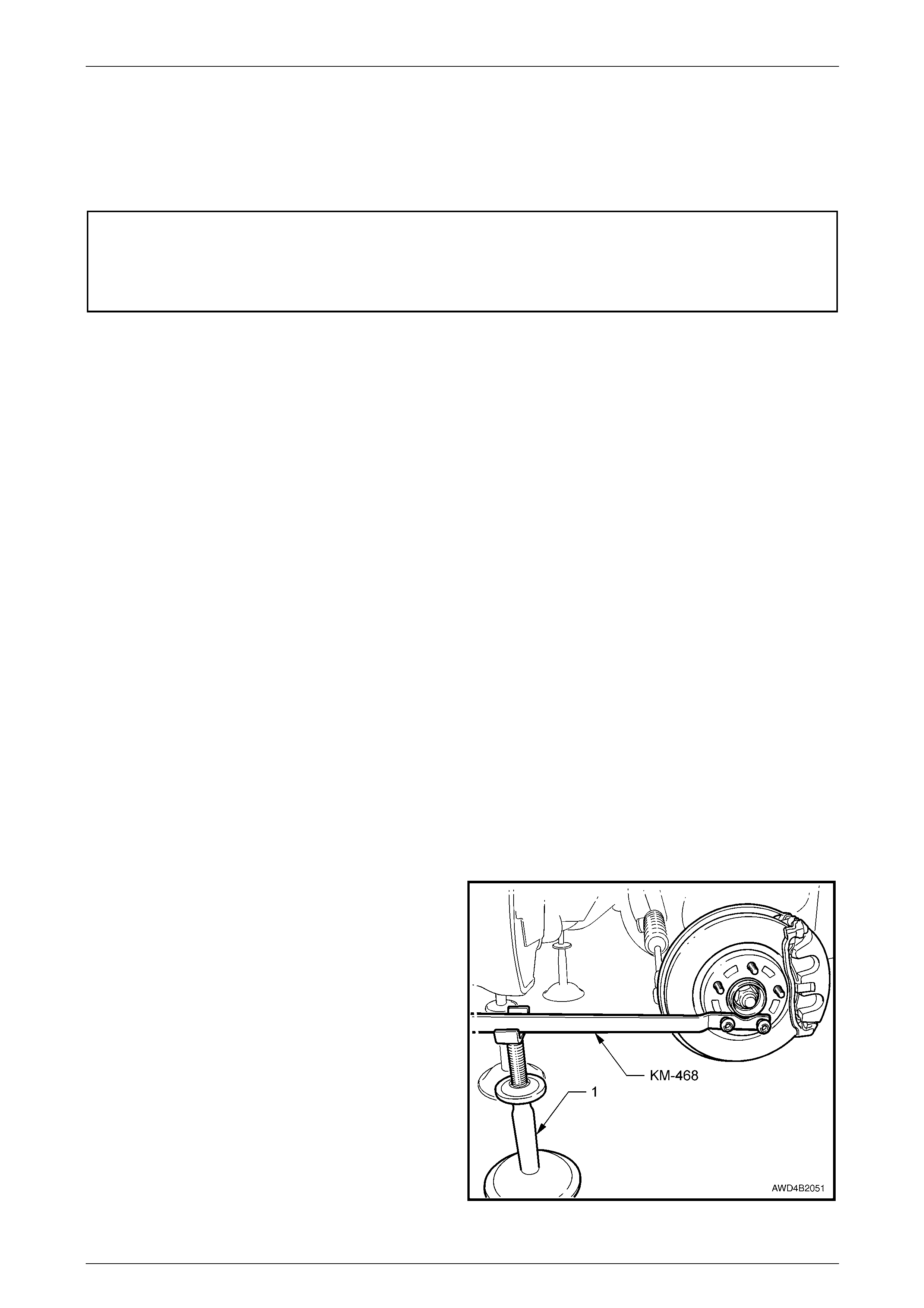
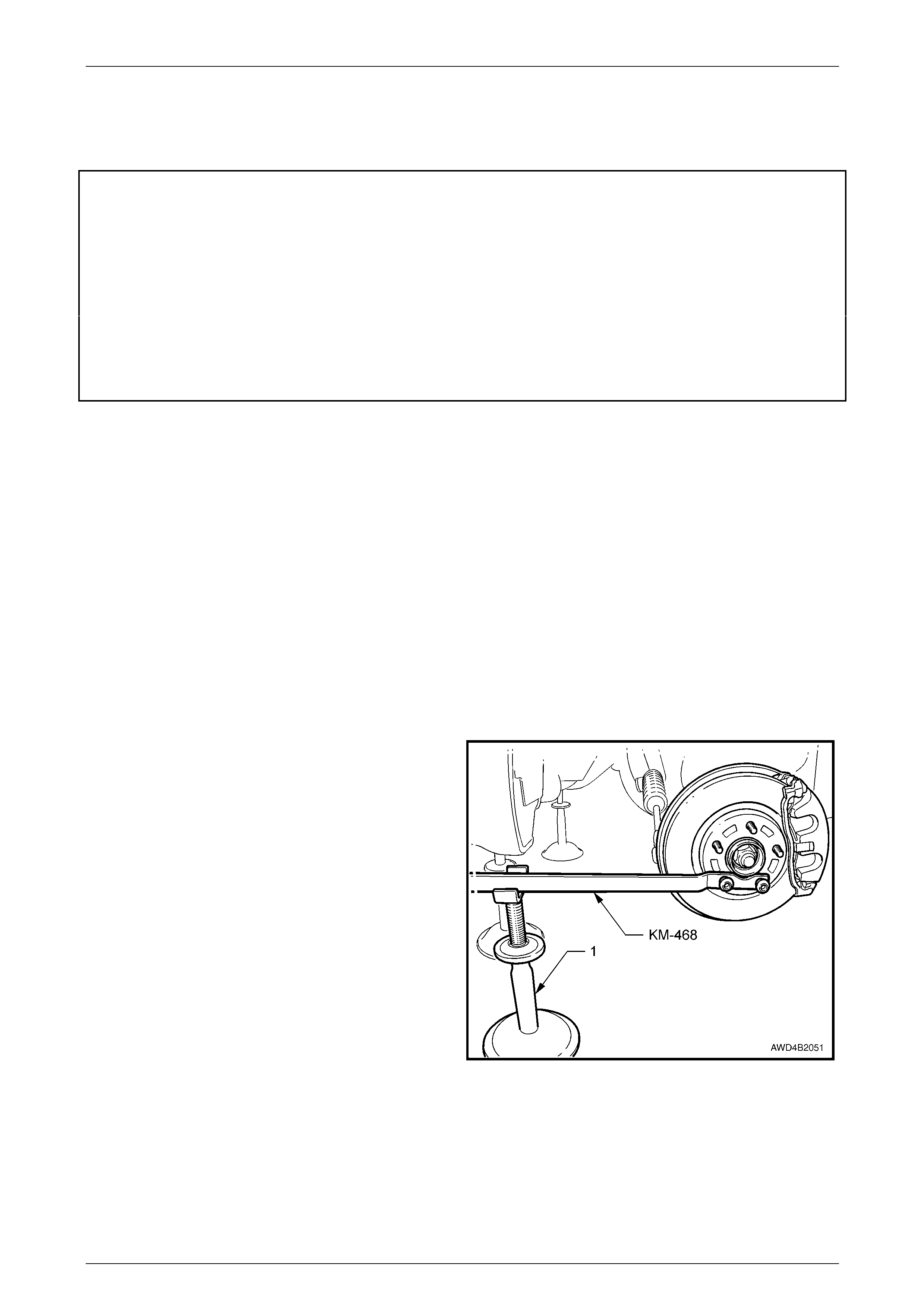
4 Attach holding tool KM-468 to the wheel hub with two
inverted wheel nuts. Support the tool outer end on a
safety stand (1).
5 Using a 36 mm socket and suitable socket equipment,
loosen then remove the driveshaft retaining nut and
flat washer. Discard the removed nut.
Figure 3 – 15
Suspension Page C-18
Page C-18
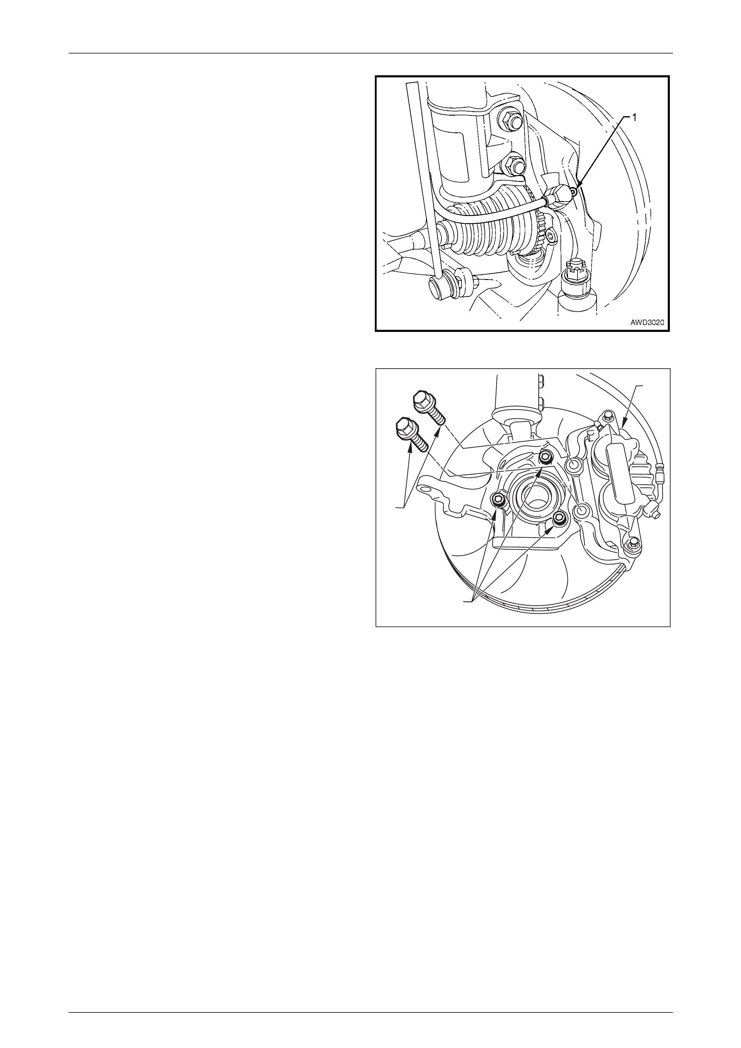
6 Remove the Allen key headed screw (1) securing the
wheel speed sensor to the steering knuckle, grasp the
sensor and twist back and forth while pulling, to
remove. Secure sensor with tie wire or similar to
prevent sensor damage during the service procedure.
7 Remove the front driveshaft. Refer to
2.4 Driveshaft Assembly, Remove, in Section 4B2
Front Final Drive, Bearing Housing & Driveshafts, in
the MY 2004 AWD Wagon Service Information. To
remove and reinstall Lower Control Arm Ball Joint refer
to 3 Front Suspension in MY2004 AWD Coupe Service
Information.
Figure 3 – 16
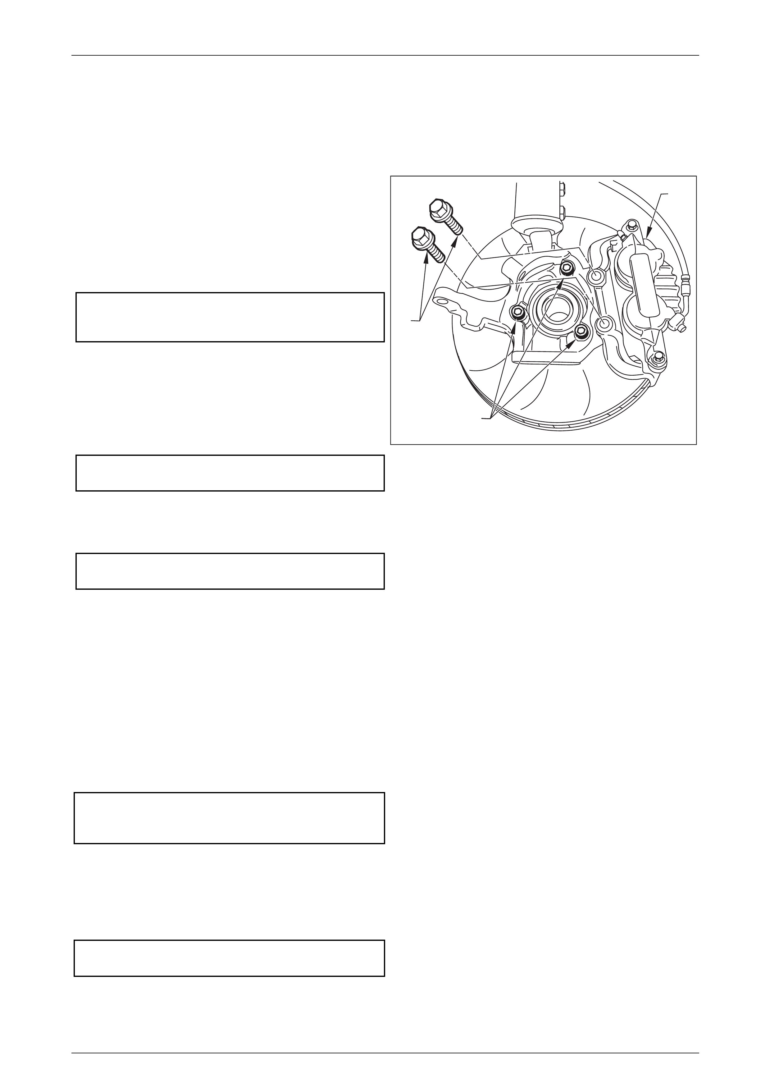
8 Remove the brake caliper retaining bolts (1), then lift
the caliper assembly (2) from the brake rotor. Position
caliper in such a way that no strain is placed on the
brake hose. If necessary, tie caliper to the suspension
spring with a piece of wire. THE CALIPER IS NOT TO
HANG BY THE BRAKE HOSE. Discard the removed
caliper bolts as they must be replaced on reassembly.
9 Even though the brake rotor to hub location is marked
in production, ensure that the rotor to hub position is
carefully marked, to ensure the correct relationship on
reassembly.
NOTE
This is necessary to overcome the possibility of
inducing a brake shudder condition after
reassembly.
10 Remove the brake rotor from the wheel hub assembly
and carefully set to one side.
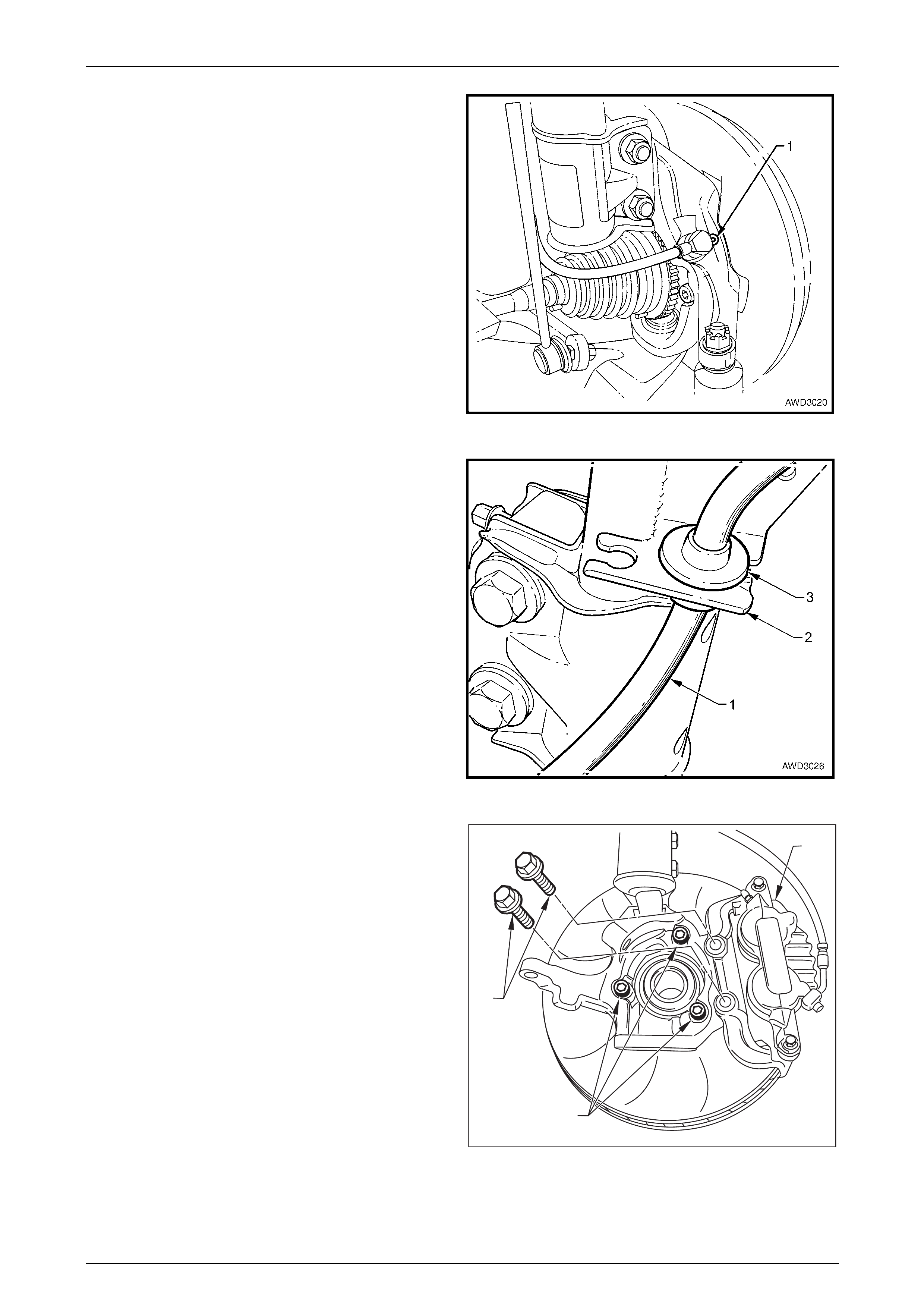
11 Using a commercially available 10 mm Allen key
socket and suitable socket equipment, loosen each of
the three bolts (3) holding the wheel bearing hub to the
steering knuckle.
2
3
1
Figure 3 – 17
12 If the hub is a tight fit to the knuckle, it may be necessary to loosen the three bolts and tap on the heads.
DO NOT STRIKE THE HUB, NOR THE WHEEL BEARING.
13 Remove the three bolts and then the hub from steering knuckle.
Inspect
1 Check wheel studs are pressed firmly into the front wheel hub assembly and ensure threads are not damaged. If
one or more of the wheel studs require replacement, refer to 3.3 Front Wheel Hub Studs in this Section for details.
2 If a check before hub removal showed that the wheel bearing angular 'float' exceeded specification, if rotation of the
hub feels 'gritty' or rough, or if a grease leak is evident, then the hub and bearing assembly must be replaced as a
unit.
3 Examine the brake rotor for scores or damage. If either of these conditions exist, the brake rotor should be
machined or replaced. Refer to Section 5A, Service and Park Braking System, in the MY2003 VY and V2 Series
Service Information, for details.
Suspension Page C-19
Page C-19
Reinstall
Installation of the front wheel hub assembly and brake rotor is the reverse of removal procedures, except for the following
points:
1 Before reinstalling the hub, inspect both mating surfaces to make sure that they are clean and free from burrs that
could prevent correct alignment of both parts, once installed.
2 Install the hub assembly onto the steering knuckle.
NOTE
The holes will only align in one position.
3 Install the three attaching bolts and washers (3) and
tighten to the correct torque specification.
Front wheel hub assembly to
steering knuckle attaching bolt
torque specification............................................108 N.m
Reinstall the front driveshaft. Refer to
2.4 Driveshaft Assembly, Reinstall, in Section 4B2 Front
Final Drive, Bearing Housing & Driveshafts in the MY 2004
AWD Wagon Service Information, for the procedure.
4 Reinstall lower ball joint into knuckle and torque ball
joint nut to specification.
Front control arm ball joint assembly stud nut
torque specification......................................70 N.m±35º
5 Reinstall the wheel speed sensor to the steering
knuckle, reinstall the securing screw and tighten to the
correct torque specification.
Front wheel speed sensor retaining
screw torque specification ...................................10 N.m
7 Install brake rotor, aligning the marks made before
removal.
2
3
1
Figure 3 – 18
NOTE
If the hub was replaced, then runout checks must
be carried out on the installed brake rotor. Refer
to Section 5A Service and Park Braking System,
in the MY 2003 VY and V2 Series Service
Information, for important information regarding
these checks.
8 Install the brake caliper (2) and new attaching bolts (1) and tighten to the correct torque specification.
( ) Brake caliper anchor plate
retaining bolts torque specification............ 85 N.m then
...............................................................turn through 30°
8 Install the road wheel, aligning the marks made prior to removal and secure with the attaching nuts.
9 Remove the jack stands and lower the vehicle.
10 Tighten the road wheel attaching nuts to correct torque specification, working in a ‘star’ pattern, refer to
Section 10 Wheels and Tyres, in the MY 2003 VY and V2 Series Service Information.
Road wheel attaching nut
torque specification............................................125 N.m
11 Install the decorative wheel nut caps.
Suspension Page C-20
Page C-20
3.3 Front Wheel Hub Studs
LT Section No. – 06-212
ATTENTION
The following fasteners MUST be replaced when p erfo rmin g these operations:
Brake caliper anchor plate to steering knuckle retaining bol t.
Replace
1 Remove the front wheel hub assembly. Refer to 3.2 Front Wheel Hub Assembly, Brake Rotor Remove, in this
Section. NOTE
Hub removal is necessary, because there is
insufficient space behind the hub flange to
remove the stud with the hub assembly installed
to the steering knuckle.
Under no circumstances is a hammer to be
used in either stud removal or installation
operations. If a hammer is used, distortion of
the wheel hub flange will most probably
result.
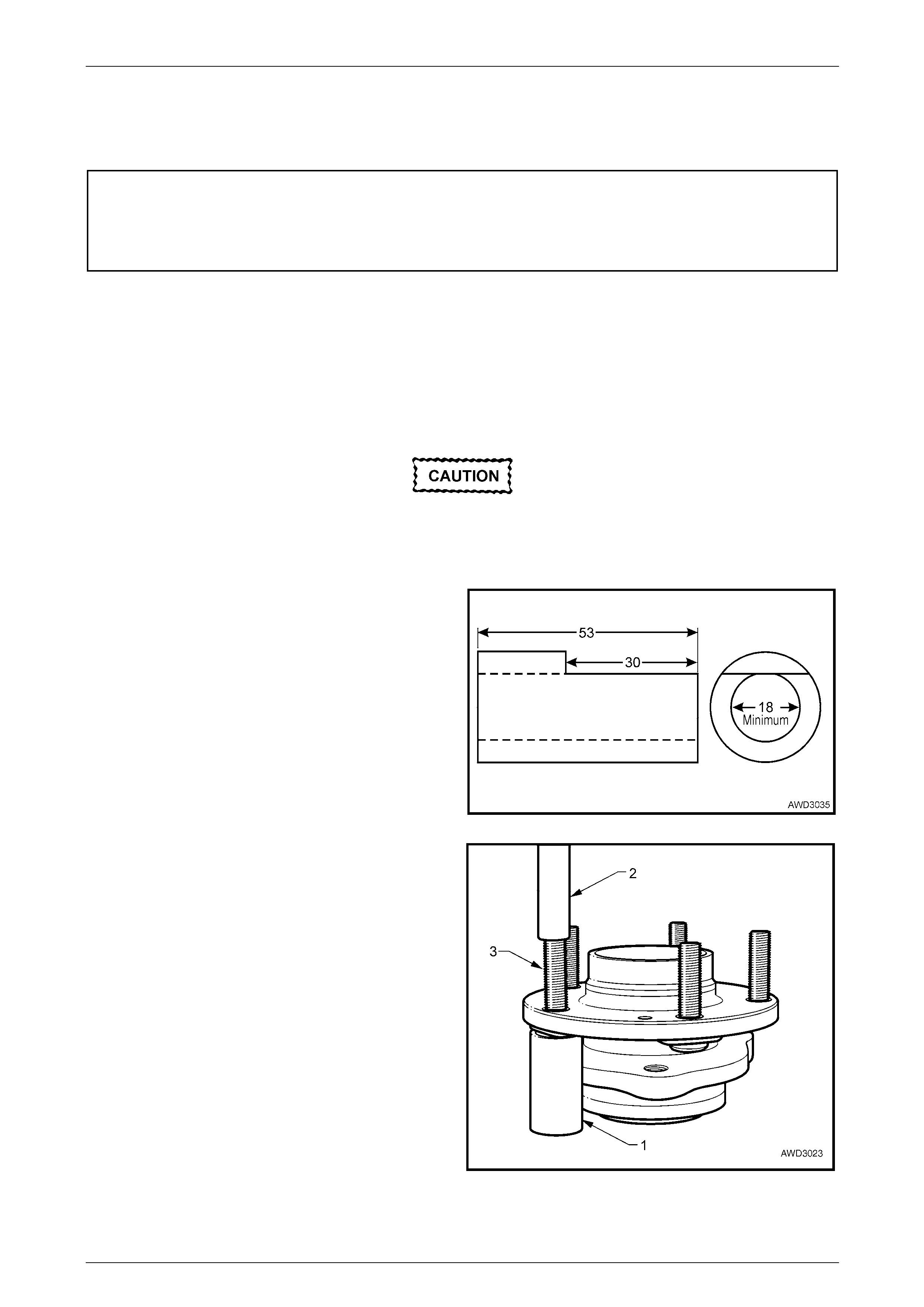
2 Fabricate a piece of thick walled pipe (i.e. 25 mm
water pipe), removing a section, as indicated. As this
single piece is used to both remove and install a new
stud, squaring the ends in a lathe is recommended.
Figure 3 – 19
3 Arrange the fabricated pipe (1) over the head of the
stud to be removed, with the flat of the cut-out section,
against the hub flange, then use a suitable drift (2) to
press the stud (3) from the wheel hub flange.
Figure 3 – 20
Suspension Page C-21
Page C-21
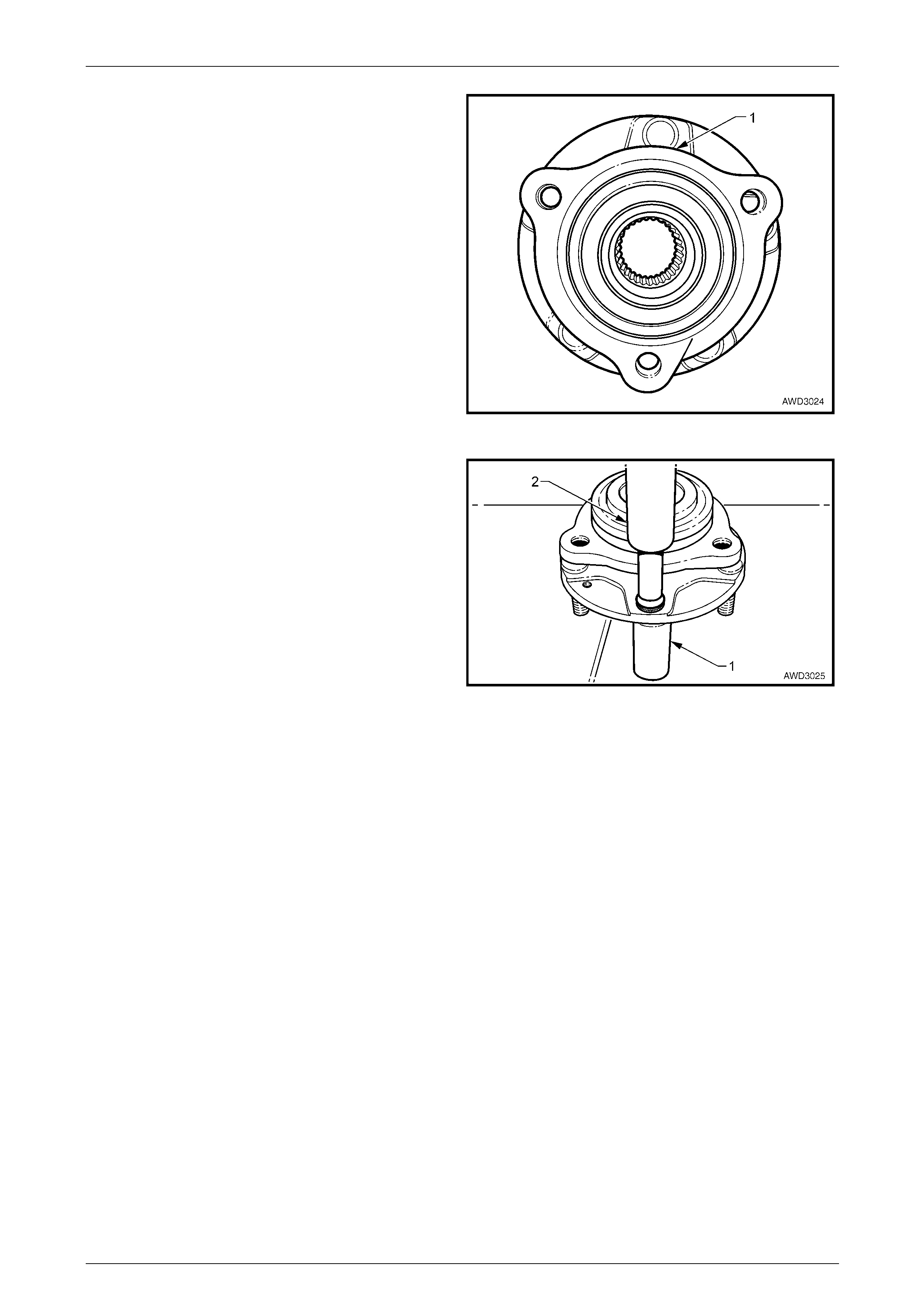
NOTE
Of the three wheel hub flanges, there is only one
(1) that provides sufficient clearance to allow
removal of the wheel stud.
Figure 3 – 21
4 Setup the wheel bearing hub with the pipe (1) under
the flange hole where the new stud is to be installed.
5 Use the same drift (2), press the stud into the wheel
hub flange, until fully installed.
NOTE
If the press effort was minimal during installation
or the stud is loose in the flange when installed,
then replace the front wheel bearing hub and
flange assembly.
6 Reinstall the front wheel hub assembly. Refer to
3.2 Front Wheel Hub Assembly, Brake Rotor and/or
Brake Shield, Reinstall, in this Section.
7 Reinstall the front driveshaft. Refer to
2.4 Front Driveshaft Assembly, Reinstall, in Section
4B2 Front Final Drive, Bearing Housing & Driveshafts
in the MY 2004 AWD Wagon Service Information.
Figure 3 – 22
Suspension Page C-22
Page C-22
3.4 Front Strut Assembly
LT Section No. – 06-212
ATTENTION
The following fasteners MUST be replaced when p erfo rmin g these operations:
Upper strut locating plate retaining nut.
Brake caliper anchor plate to steering kn u ckle retain ing bolts.
Steering knuckle to strut attaching nuts and bolts.
Remove
1 Observing the jacking precautions as outlined in 2.3 Jacking Precautions in this Section, raise the front of the
vehicle and support on safety stands.
2 Remove the decorative wheel nut caps.
3 Mark the relationship of the road wheel to hub or brake rotor. Loosen, then remove the road wheel attaching nuts,
working in a 'star' pattern. Refer to Section 10, Wheels and Tyres, in the MY 2003 VY and V2 Series Service
Information, for detailed information. Remove the road wheel.
NOTE
Step 3 is necessary to maintain part relationships
and to avoid brake rotor distortion and the
creation of brake shudder, after the vehicle is
placed back in service.
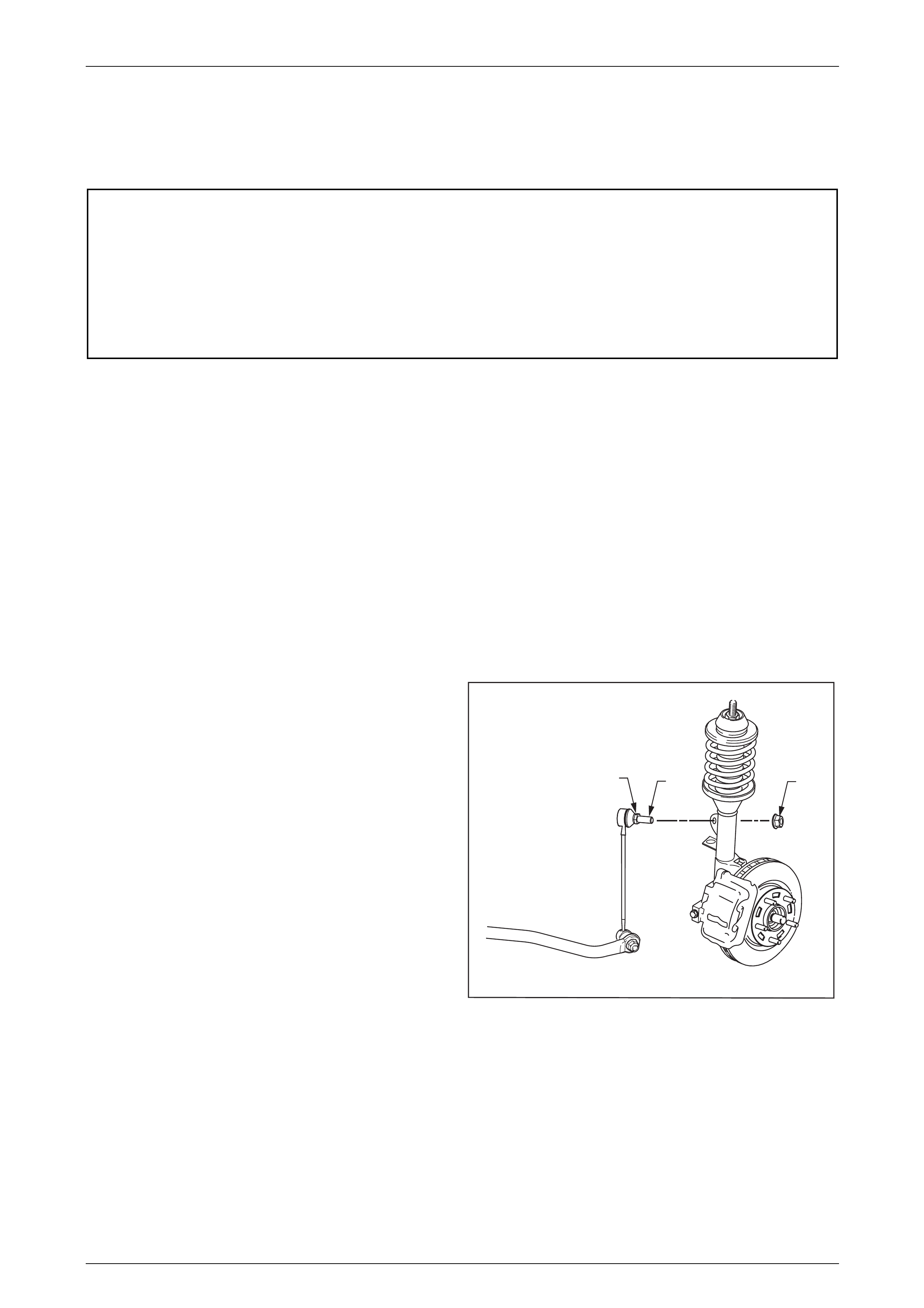
4 Position a suitable size open end spanner to hold the
socket stud (1) at ‘A’, then use another spanner to
loosen and remove the nut (2).
5 Disconnect the wheel speed sensor cable and
insulator from the strut bracket.
12
A
Figure 3 – 23
Suspension Page C-23
Page C-23
6 To avoid placing strain on the wheel speed sensor
cable, remove the Allen key headed screw (1)
securing the front wheel speed sensor to the steering
knuckle.
7 Grasp the sensor and twist back and forth while
pulling, to remove. Secure sensor with tie wire or
similar to prevent sensor damage during the service
procedure.
Figure 3 – 24
8 Remove the brake hose (1) from the strut housing
bracket (2) by turning the plastic sleeve (3) on the
hose until the flats on the sleeve align with the bracket
opening.
Figure 3 – 25
9 Remove the brake caliper retaining bolts and washers
(1), lift the caliper assembly (2) from the brake rotor
and support in such a way that no strain is placed on
the brake hose. THE BRAKE CALIPER IS NOT T O
HANG BY THE BRAKE HOSE. Discard removed bolts
as they must be replaced on reassembly.
10 Remove the brake rotor from the wheel hub assembly.
The brake rotor to hub relationship is marked during
production. To ensure this relationship is maintained,
ensure that the rotor to hub position is carefully
marked.
NOTE
• This is necessary to overcome the possibility
of inducing a brake shudder condition after
reassembly
• These two steps are primarily aimed at
reducing the weight of components that will
need to be supported after the strut to
knuckle bolts are removed.
2
3
1
Figure 3 – 26
11 Position a suitable floor jack fitted with a block of wood on the lift pad under the front control arm and raise it
enough to support the weight.
Suspension Page C-24
Page C-24
Unless the front wheel hub, knuckle and dust
shield are supported when the two strut to
knuckle bolts and nuts are removed, these
components will fall outward. Apart from the
risk of personal injury, the driveshaft inner
tripot joint will be separated, resulting in the
need to replace the joint and dust boot.
12 While supporting the front wheel hub, steering knuckle and dust shield, loosen, remove then discard the two lower
strut to knuckle attaching bolts and nuts.
13 While continuing to support the steering knuckle pull it clear from the strut.
14 Ensure that the steering knuckle is maintained in a 'normal' attitude, by securing with wire to the brake pipe bracket.
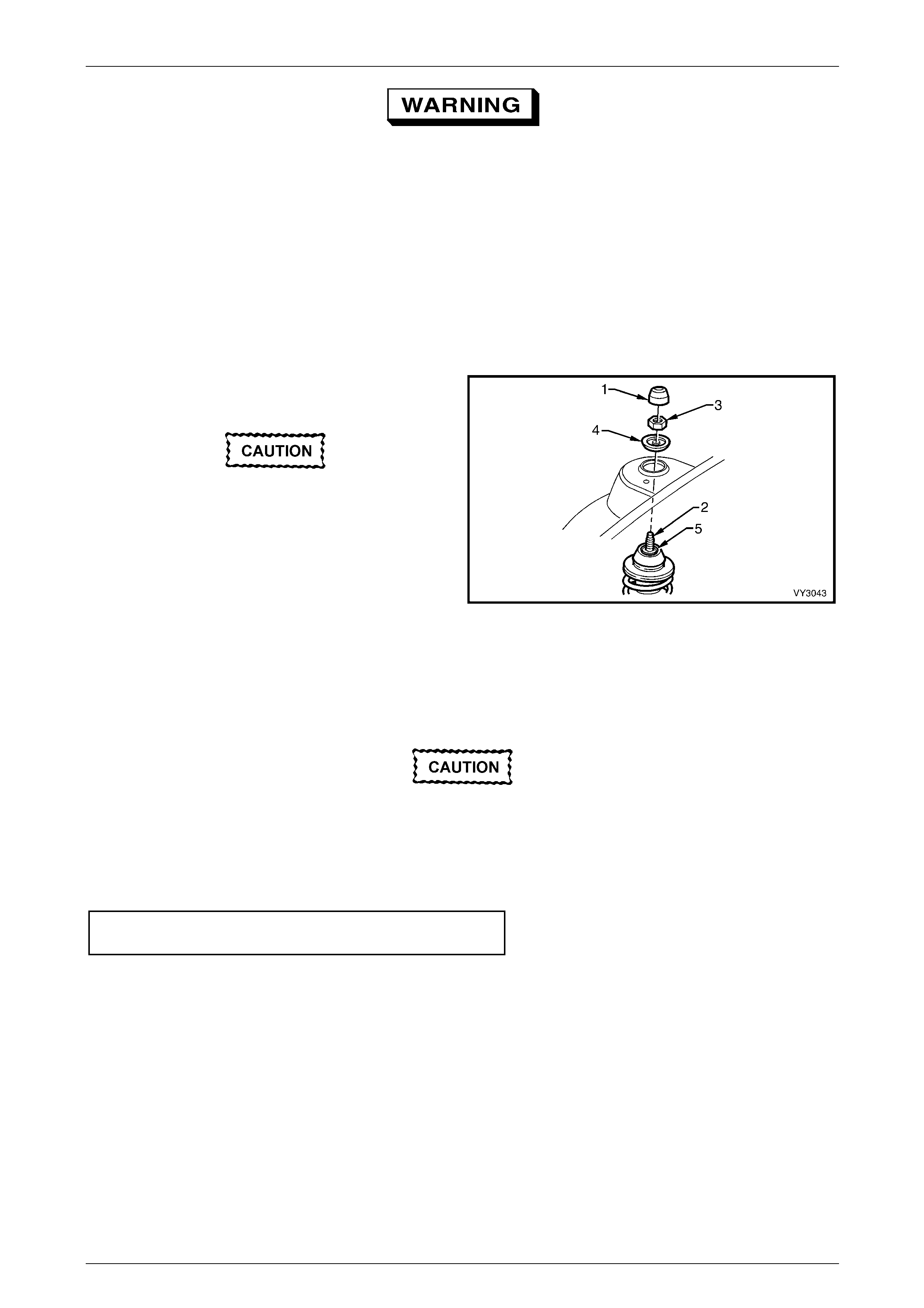
15 Remove the dust cover (1) from the upper strut
support, in the engine compartment.
Support the strut assembly, w hile performing
the next step, to stop the strut falling free,
causing possible damage.
16 While holding the strut rod shaft (2) with a 10 mm
socket, remove the self-locking nut (3), using a 24 mm
ring spanner, then remove the locating disc (4).
Discard the strut rod nut.
17 Carefully lower the strut (5) from the tower, manipulate
the strut to remove the stabiliser stud from the bracket
on the strut and remove the assembly from the
vehicle.
Figure 3 – 27
Reinstall
The torque of the strut bearing retaining nut
MUST be checked for correct tightness
BEFORE installing the strut into th e vehicle.
1 Use a 10 mm socket to hold the strut rod from turning, then tighten the strut bearing retaining nut (‘5’ in Figure 3-29)
to the correct torque specification, using a 24 mm ring spanner with a torque wrench attached.
Upper strut bearing retaining
nut torque specification…………78 N.m
2 Manipulate the strut assembly so that the stabiliser socket stud is located in the strut bracket, then locate the strut
assembly into the spring strut tower.
3 After installing the locating disc, partially install a NEW upper nut to the strut rod. Do not tighten at this time.
Suspension Page C-25
Page C-25
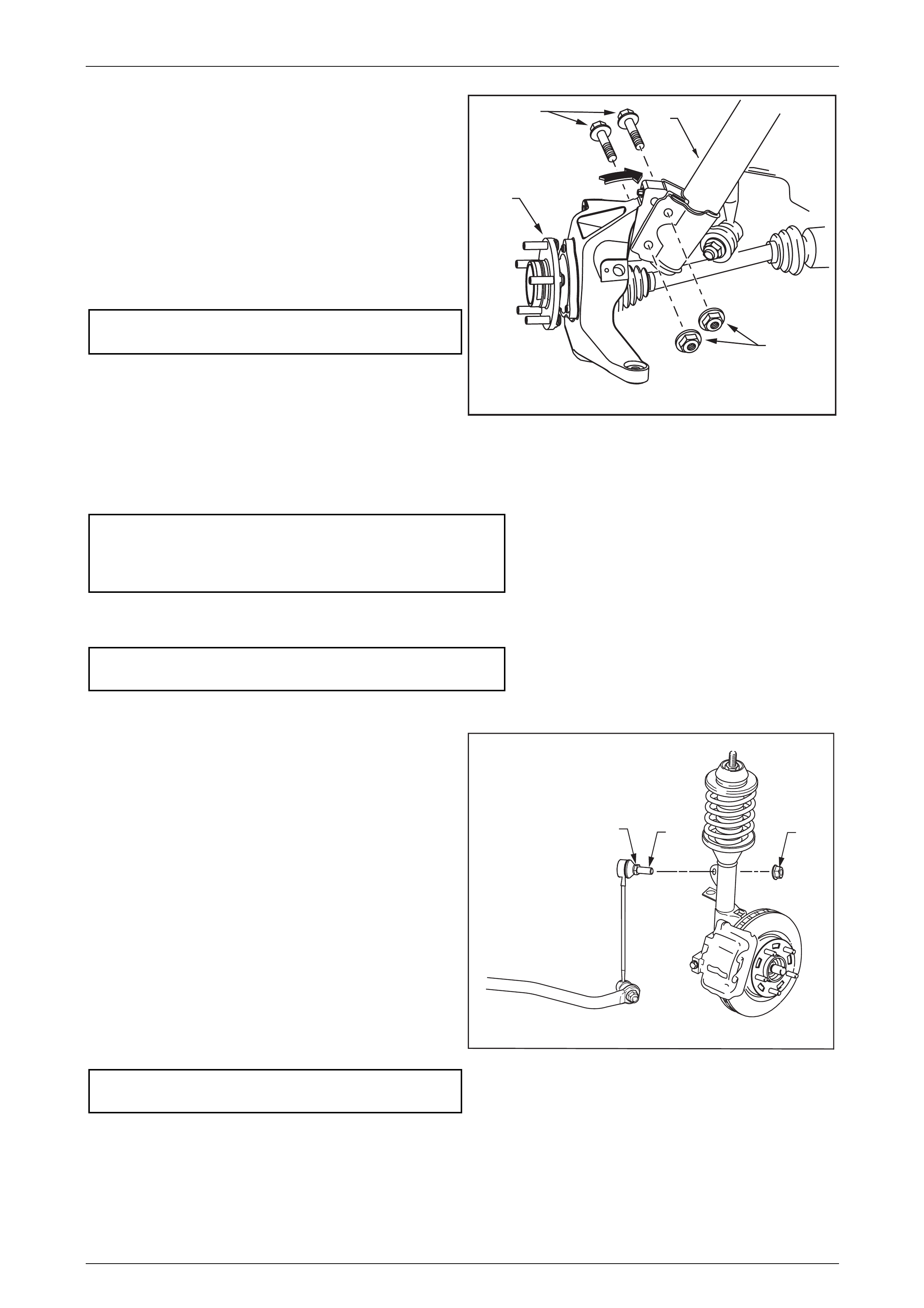
4 While supporting the steering knuckle and hub
assembly (1), remove the securing wire and align the
knuckle holes sufficiently to line up the bolt holes in the
steering knuckle and the lower end of the strut
assembly (2).
5 Install NEW retaining bolts (3) (from front to rear) and
nuts (4), and tighten to a preliminary torque of 85 Nm.
6 Use a 10 mm socket to hold the strut rod from turning,
then tighten the upper strut rod retaining nut (‘3’ in
Figure 3-27) to the correct torque specification, using a
24 mm ring spanner with a torque wrench attached.
( ) Upper strut locating plate
retaining nut torque specification .........................55 N.m
7 Install the brake hose to the strut bracket by turning
the plastic sleeve on the hose until the flats on the
sleeve align with the bracket opening.
1
2
3
4
Figure 3 – 28
8 Reinstall the brake rotor, aligning the marks made prior to removal.
9 Reinstall the brake caliper, tightening the NEW attaching bolts to specification.
( ) Brake caliper anchor plate
retaining bolts torque
specification……………………….85N.m
then turn through 30°
10 Reinstall the wheel speed sensor to the steering knuckle, securing with the Allen key headed screw and tightening
to the correct torque specification.
Front wheel speed sensor attaching
screw torque specification………..10 N.m
11 Reinstall the sensor lead and insulator into the strut mounting bracket.
12 Reinstall the stabiliser bar socket stud nut (2) after
ensuring that all the components are assembled as
shown. While holding the socket stud (1) with a
suitable open end spanner at ‘A’, use another spanner
to tighten the upper retaining nut until the end of the
thread on the stud is contacted.
NOTE
Do not use power tools for this tightening
operation, otherwise thread damage will result.
13 Reinstall the road wheel, aligning the marks made
prior to removal.
14 Remove the safety stands and lower vehicle.
15 Tighten road wheel attaching nuts to the correct torque
specification, working in a ‘star’ pattern, refer to
Section 10, Wheels and Tyres, in the MY 2003 VY and
V2 Series Service Information.
Road wheel attaching nut
torque specification............................................125 N.m
12
A
Figure 3 – 29
16 Install the decorative wheel nut caps.
17 Bounce the vehicle up and down several times to settle the suspension.
18 Check and correct the wheel alignment, as required. Refer to 2.2 Wheel Alignment Checking and Adjustment, in
this Section.
Suspension Page C-26
Page C-26
3.5 Upper Strut Support Bearing and Mount
LT Section No. – 06-210
Remove
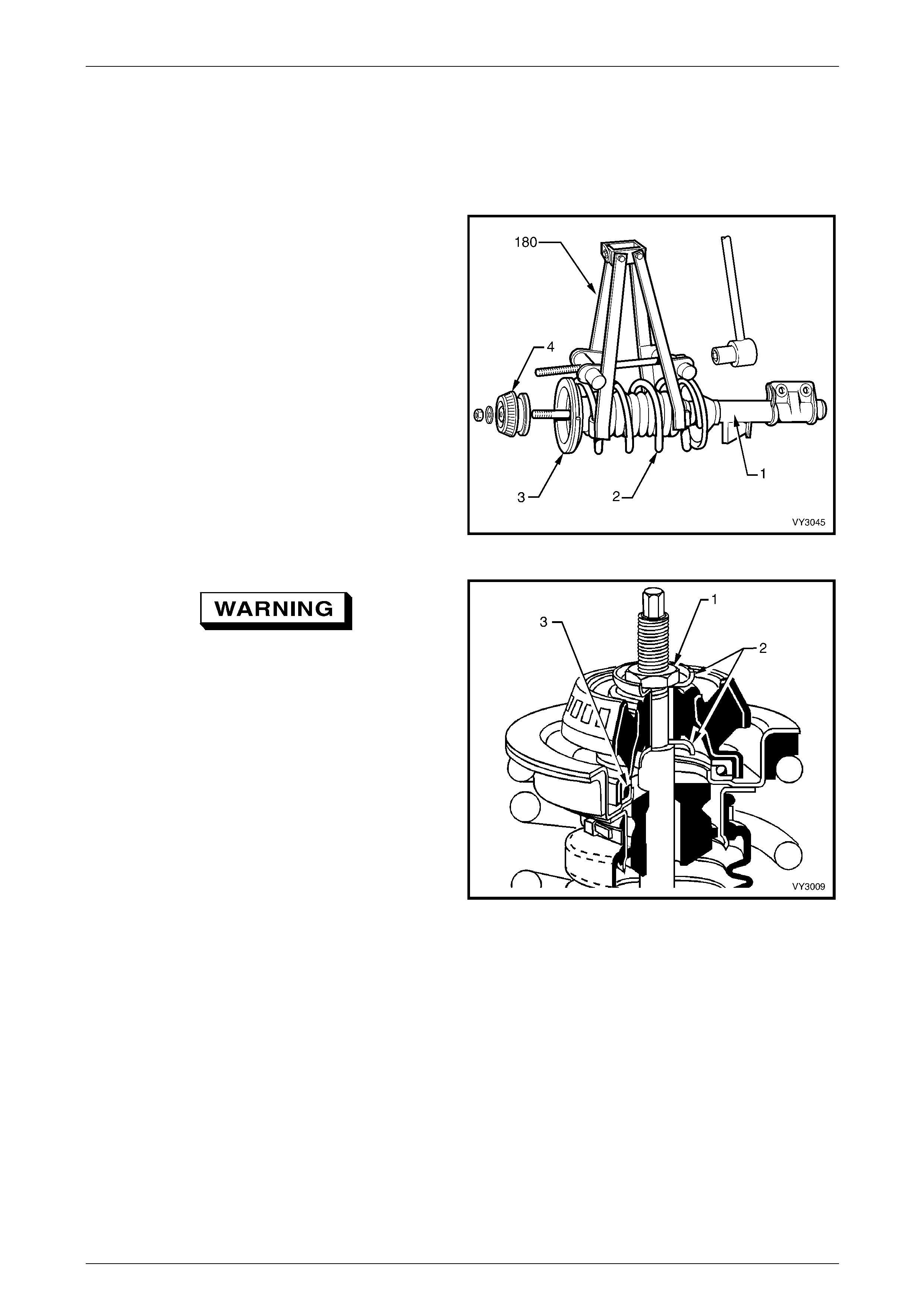
1. Remove the front strut (1), refer to
3.4 Front Strut Assembly, in this Section.
2. Fit Tool No. 180 (or a commercially available
equivalent) to the front spring as shown. Compress the
spring (2) until the upper support bearing (4) has
clearance at the spring seat collar 3).
Figure 3 – 30
Do not attempt to remove the retaining nut (1)
from the strut rod shaft before compressing
the spring.
3. While holding the strut rod shaft with a 10 mm socket,
remove the upper strut bearing to strut rod retaining
nut (1), using a 24 mm ring spanner.
4. Remove the front suspension strut mount assembly
and the two washers (2) fitted to each side.
NOTE
The lower washer may be stuck to the lower
surface of the mount.
5. Remove the strut bearing (3) from the upper spring
seat collar, taking particular note of the bearing
orientation.
NOTE
• The upper support bearing is self-lubricated
and no servicing requirements are
necessary. If considered to be faulty, the
bearing is to be replaced as an assembly.
• Under no circumstances is the machined
surface of the piston rod section to be
gripped directly on its outer surface.
Figure 3 – 31

Suspension Page C-27
Page C-27
Reinstall
1. Loosely reinstall the strut rod nut, then pull the piston rod through the upper spring seat to its maximum length, then
remove the strut rod nut.
2. Install the upper bearing with the same orientation as noted on removal. Usually, the coloured or narrow, outer
section, faces down to the upper spring seat collar.
3. While holding the strut rod extended and, after installing the first mount washer with the dished shape facing
downward (refer to item 2 in Figure 3-33), install the upper front suspension strut mount assembly over the bearing
and washer.
4. Install the second washer with the dished shape facing upward (refer to item 2 in Figure 3-33) and install the
retaining nut.
5. Using a 10 mm socket and a 24 mm ring spanner with a torque wrench attached, tighten the nut to the correct
torque specification.
Upper strut bearing retaining
nut torque specification........................................78 N.m
6. Release the spring compressor and remove it from the spring.
7. Install the front strut, refer to 3.4 Front Strut Assembly in this Section.
Suspension Page C-28
Page C-28
3.6 Front Spring
LT Section No. – 06-210
Remove
1 Remove the front strut, refer to 3.4 Front Strut Assembly in this Section.
2 Remove the front strut upper mount and bearing assembly, refer to 3.5 Upper Strut Support Bearing and Mount in
this Section.
NOTE
The spring compressor is not shown in this
exploded view, as it is assumed that Steps 1 and
2 have already been carried out.
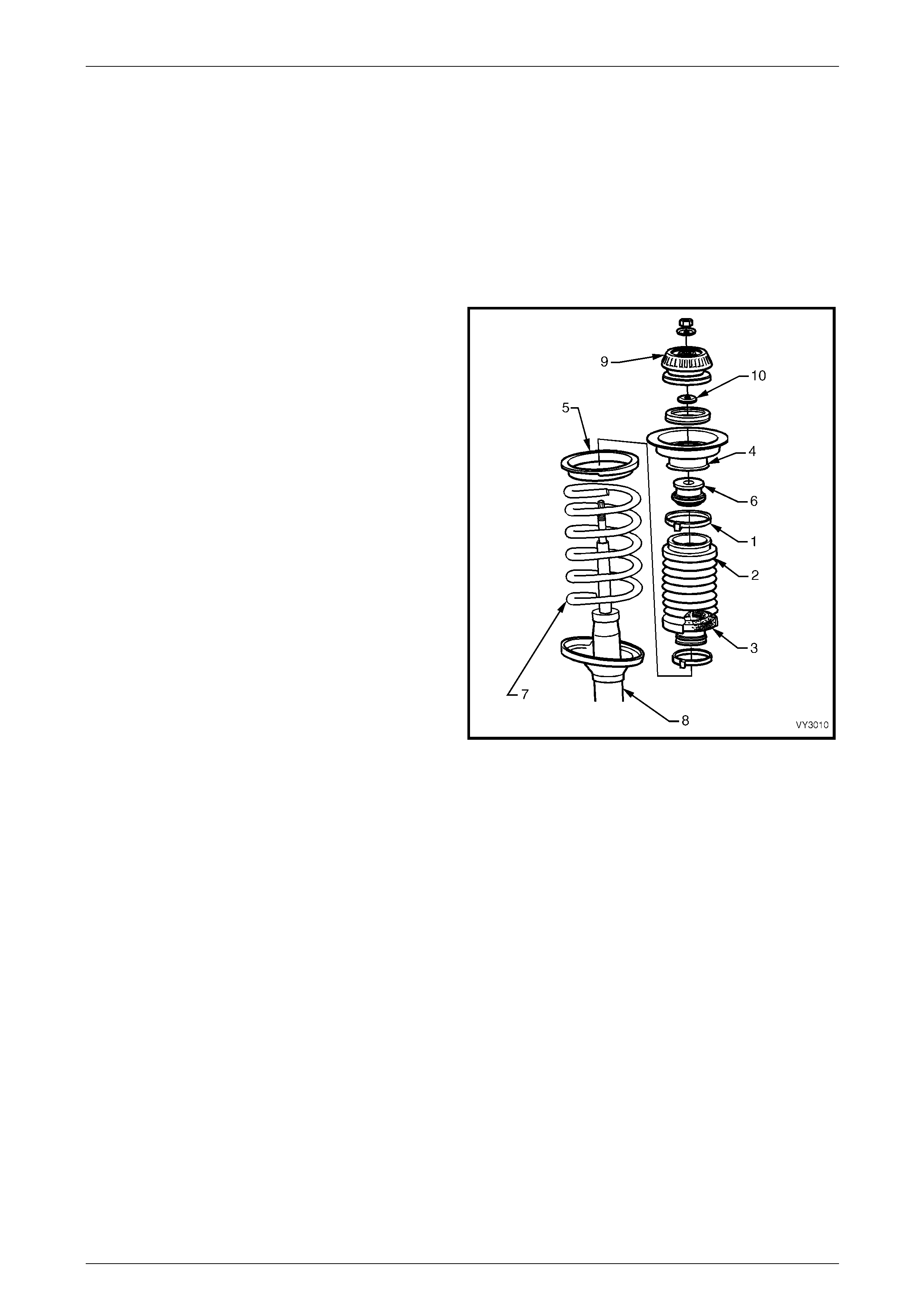
3 Remove the retaining clamp (1) securing the front strut
dust shield assembly (2) and filter (3) to the upper
spring seat collar (4).
4 Remove the upper spring seat collar (4), spring
insulator (5) and compression bumper (6) from the top
of the spring (7).
5 Remove the spring (7) from the strut (8) and release
the spring compressor.
Figure 3 – 32
Reinstall
NOTE
If installing a replacement spring, ensure that the
spring is the correct type for this vehicle.
Refer to 6 Front Suspension Specifications in this
Section for details.
1 Position spring on strut with straight projecting end of spring correctly located in the lower spring seat.
2 Install spring compressor Tool No. 180 or a commercially available equivalent to the spring (refer to Figure 3-32)
and compress it.
3 Reinstall the upper spring insulator, spring seat collar and compression bumper so that the double notch in the
upper flange of the spring seat collar is assembled, facing inward. The spring insulator has a step which locates on
to the straight projecting end of the spring.
4 Install the front strut upper bearing and support (9), refer to 3.5 Upper Strut Support Bearing and Mount in this
Section. NOTE
Check that the lower washer (10) is not binding
with the lower edge of the mount.
5 Fit the upper end of the front strut dust shield assembly over the lower flange of the spring seat collar and secure
with a retaining clamp. Tighten the clamp until the boot rubber is firmly secured to the spring seat collar flange.
6 Reinstall front strut, refer to 3.4 Front Strut Assembly in this Section.
Suspension Page C-29
Page C-29
3.7 Front Strut Unit
LT Section No. – 06-212
Replace
NOTE
When replacing the front strut, ensure that the
replacement unit is the correct type for this
vehicle. Refer to 6 Front Suspension
Specifications in this Section for details.
As the strut assembly is a sealed component, no overhaul procedures are possible. If any strut component is found to be
unserviceable, the complete strut must be replaced.
1 Remove the front strut assembly, refer to 3.4 Front Strut Assembly in this Section.
2 Remove the upper support components, refer to 3.5 Upper Strut Support Bearing and Mount in this Section.
3 Remove the spring, refer to 3.6 Front Spring in this Section.
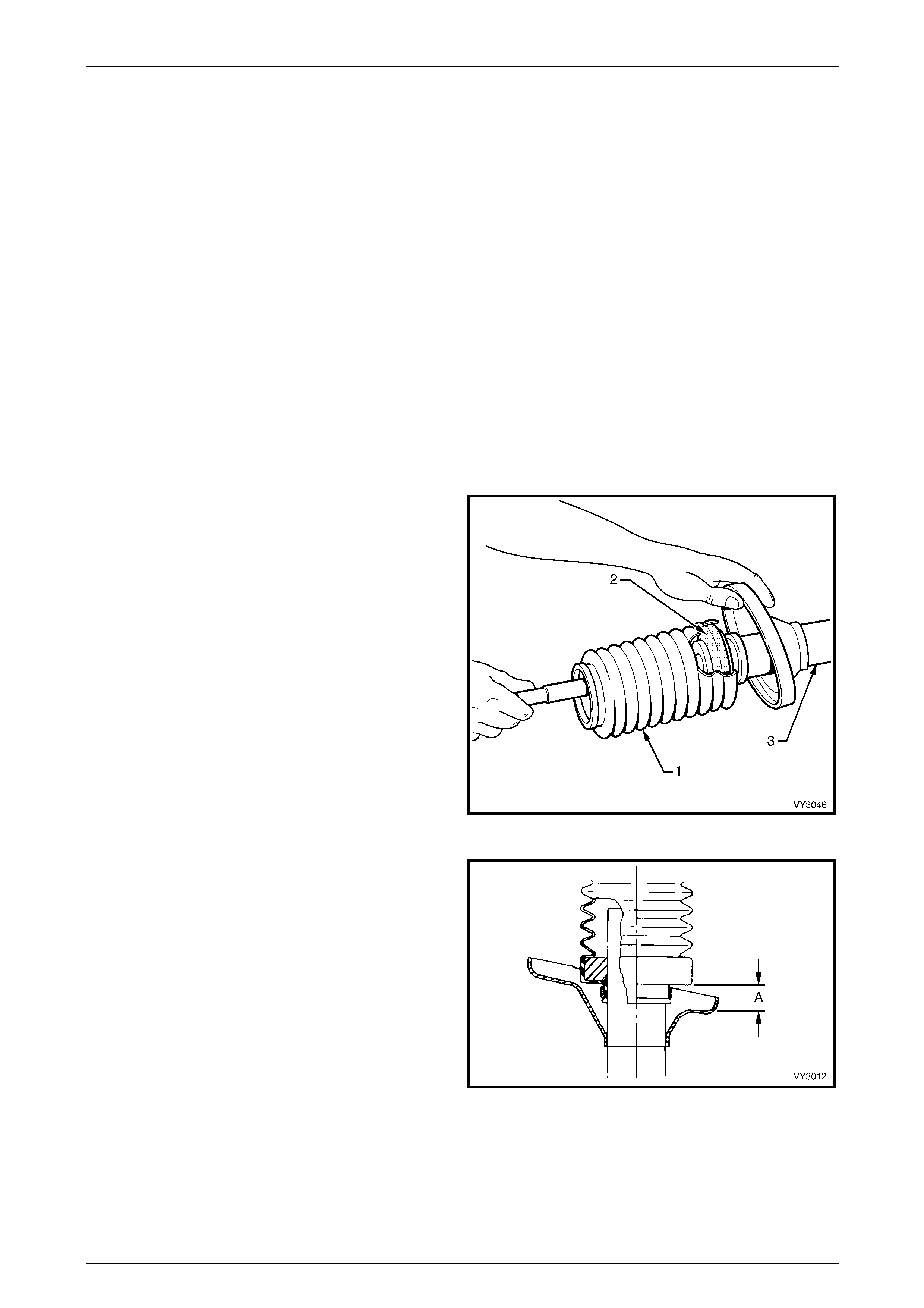
4 Remove the lower boot, worm drive retaining clamp.
Slide the front strut dust shield assembly (1) and filter
(2) from the strut assembly (3).
5 Pull the strut rod fully up and, while supporting the rod
to stop it from slipping back into the strut, reinstall the
front strut dust shield assembly over the strut tube,
ensuring that the filter (2) remains seated inside the
boot assembly (1).
Figure 3 – 33
6 Ensure that the bottom of the front strut dust shield
assembly is positioned so that distance ‘A’ is between
0 – 5 mm.
7 Install a new worm drive retaining clamp and tighten
until the rubber on the front strut dust shield assembly
is firmly secured.
8 Reinstall the front spring refer to 3.6 Front Spring in
this Section.
9 Reinstall the upper strut support assembly refer to
3.5 Upper Strut Support Bearing and Mount in this
Section.
10 Reinstall the front strut assembly refer to
3.4 Front Strut Assembly in this Section. Figure 3 – 34
Suspension Page C-30
Page C-30
3.8 Steering Knuckle
LT Section No. – 06-212
ATTENTION
The following fasteners have either micro encapsulation or incorporate a mechanical thread lock and should
only be used once. If in doubt, replacement is recommended when performing these operations:
Front control arm ball joint stud nut.
The following fasteners MUST be replaced when p erfo rmin g these operations:
Front driveshaft outer retaining nut.
Steering knuckle to strut attaching nuts and bolts.
Brake caliper anchor plate to steering kn u ckle retain ing bolts.
Remove
1 Observing the jacking precautions as outlined in 2.3 Jacking Precautions in this Section, raise the front of the
vehicle and support on safety stands.
2 Remove the decorative wheel nut caps and mark the relationship of the wheel to the hub stud, using a felt tipped
pen or similar.
3 Loosen, then remove the road wheel attaching nuts, working in a 'star' pattern.
Refer to Section 10 Wheels and Tyres in the MY 2003 VY and V2 Series Service Information, for detailed
information. Remove the road wheel.
NOTE
Steps 2 and 3 are necessary to maintain part
relationships and to avoid brake rotor distortion
and the creation of brake shudder, after the
vehicle is placed back in service.
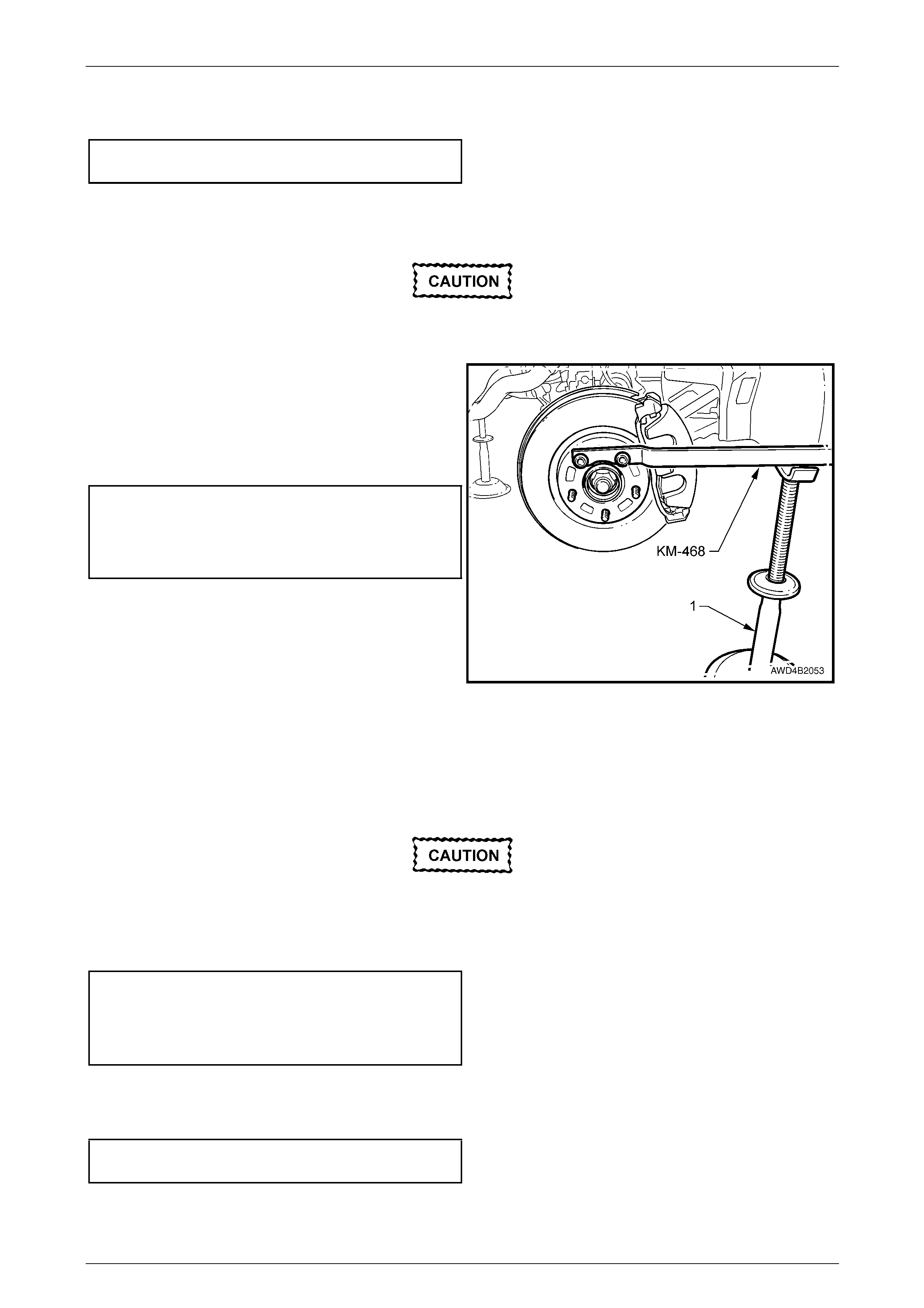
4 Attach holding tool KM-468 to the wheel hub with two
inverted wheel nuts. Support the tool outer end on a
safety stand (1).
5 Using a 36 mm socket and suitable socket equipment,
loosen then remove the driveshaft retaining nut and
flat washer. Discard the removed nut.
Figure 3 – 35
Suspension Page C-31
Page C-31
Under no circumstances is the end of the
driveshaft to be struck with a hammer to
dislodge the splines. To do so, will not only
damage the front hub bearing but the
driveshaft to outer CV joint snap ring can be
also be dislodged.
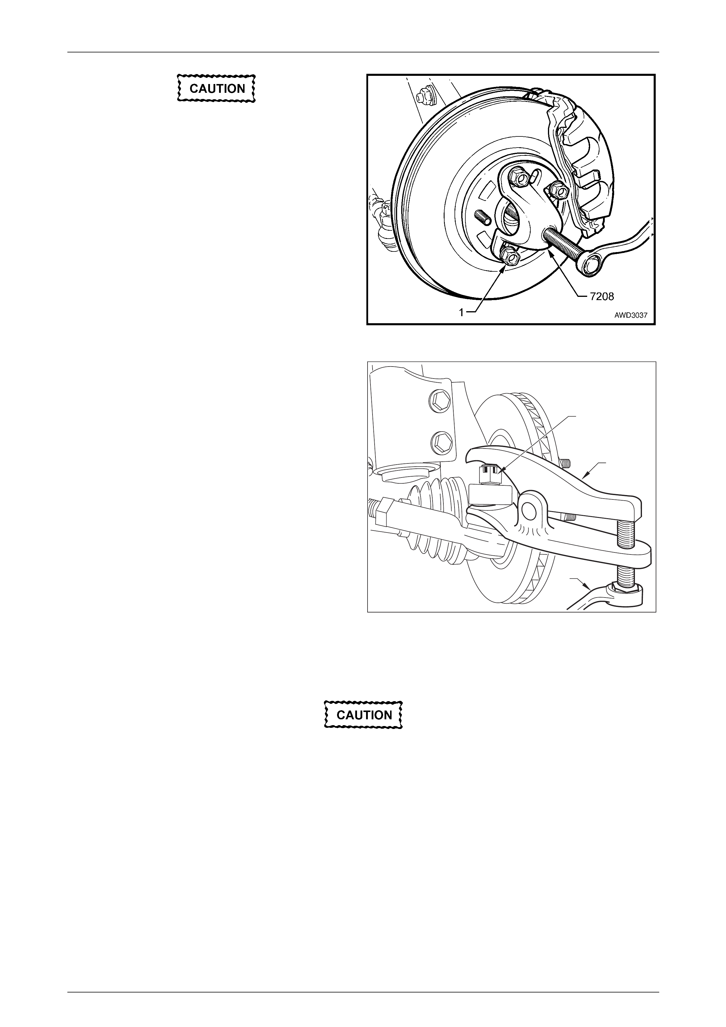
6 Install Tool No. 7208 to the front hub studs and secure
with three of the wheel nuts (1).
NOTE
If not previously modified, it will be necessary to
use a round file to lengthen the slots in Tool No.
7208, to fit over the wheel studs.
7 Tighten the forcing screw to separate the front hub and
outer driveshaft splines. Remove Tool No. 7208. Figure 3 –36
8 Remove the split pin and loosen the castellated nut (1)
until the nut is flush with the end of the tie rod end
stud.
8a Using a scraper or similar tool slide the white nylon
spacer away from knuckle to provide room for tool
E9332-A
2
1
E9332-A
Figure 3 – 37
9 Install tool E9332-A refer Fig 3-37 as shown, using a ring spanner (2) press the stud out from the steering
knuckle insert.
Under no circumstances is the knuckle to be
hit w ith a hammer. The steel insert should not
be removed from the knuckle during this
operation.
Suspension Page C-32
Page C-32
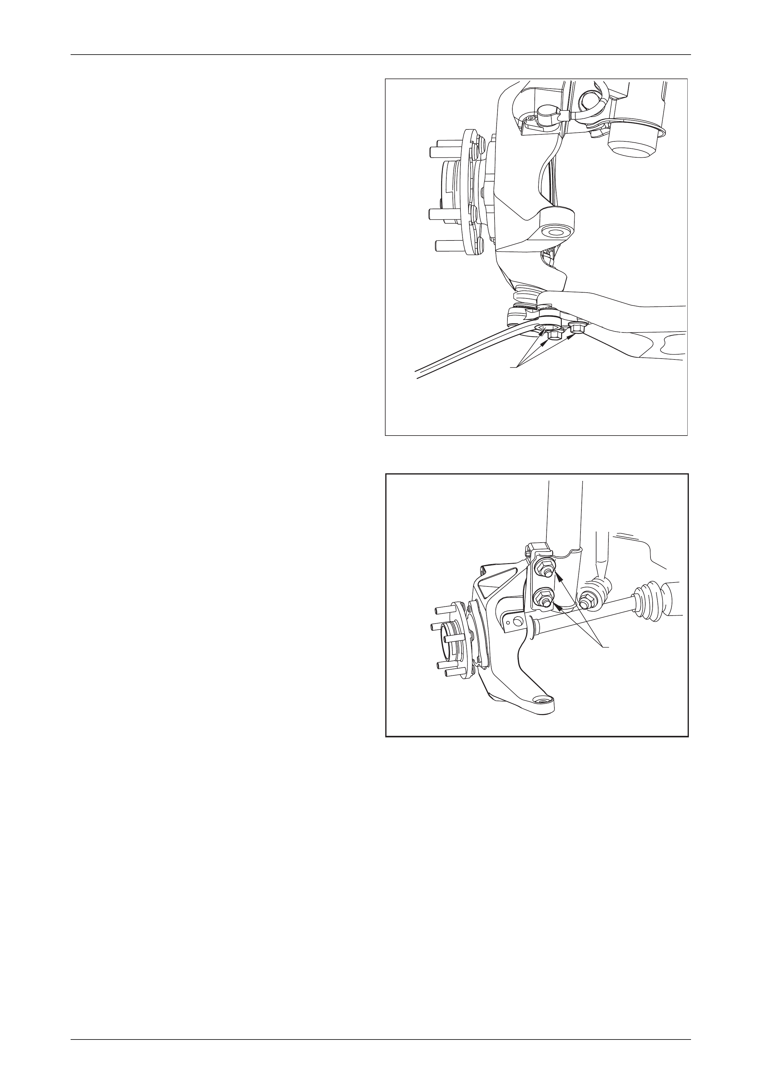
10 Loosen remove and discard 3 bolts (1) Refer Fig 3-38
holding ball joint housing to lower control arm.
11 Loosen, remove and discard the two lower strut
attaching bolts and nuts (1) Refer Fig 3-39.
1
Figure 3 – 38
12 Before removing the steering knuckle, support the
driveshaft with wire tied to the brake pipe bracket. Do
not apply the wire around the outer CV joint boot.
Driveshaft support is needed to avoid damage to the
inner tripot joint boot and to prevent joint separation,
when the steering knuckle is removed from the
vehicle.
13 Remove front hub, knuckle and ball joint housing from
vehicle.
1
Figure 3 – 39
Suspension Page C-33
Page C-33
Reinstall
Reinstallation is the reverse of the removal procedures except for the following:
1 Reinstall the front hub to the steering knuckle, reinstall the three retaining bolts and washers and tighten to the
correct torque specification.
Front wheel hub assembly to
steering knuckle attaching bolt
torque specification............................................108 N.m
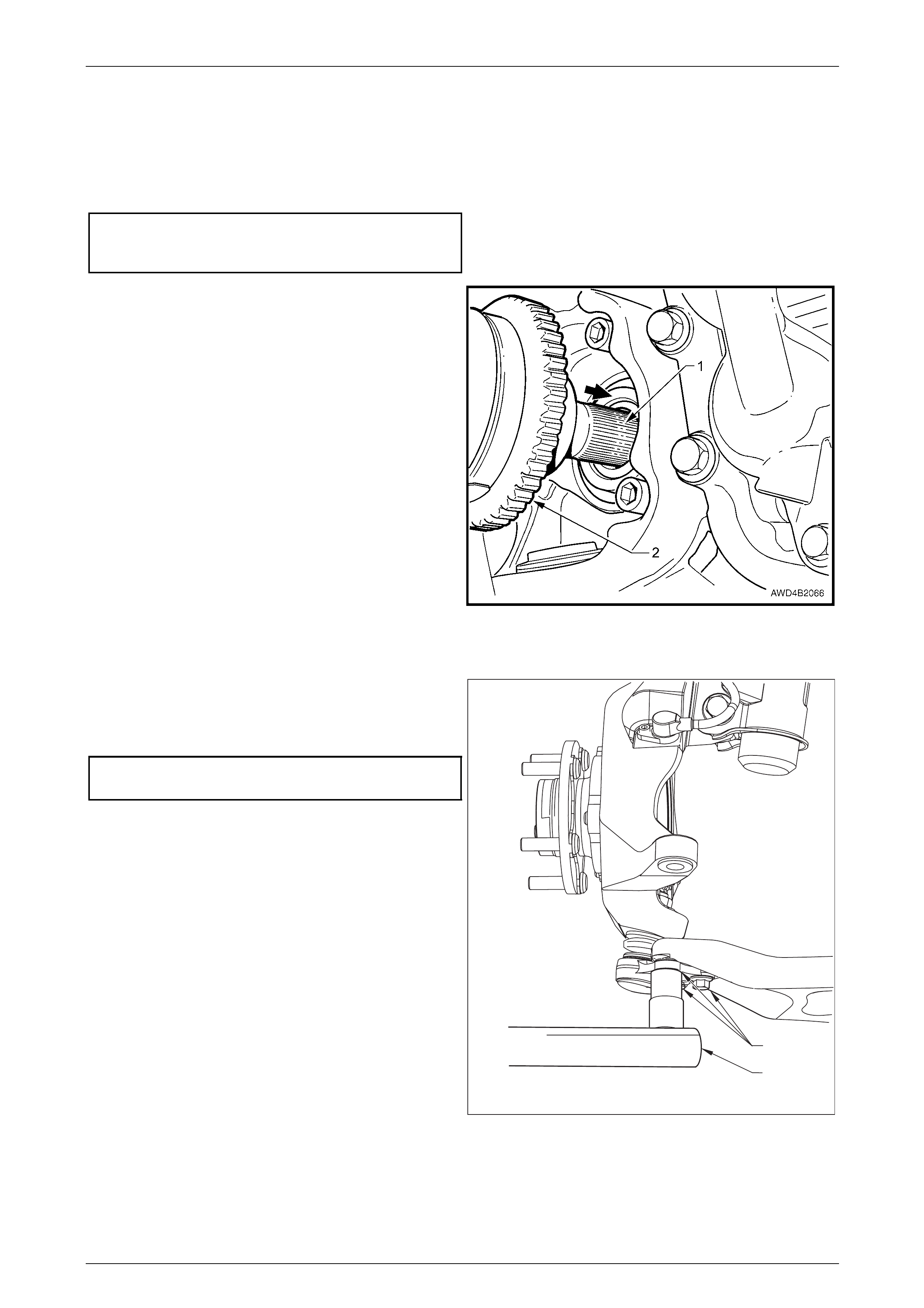
2 Lightly lubricate the outer driveshaft splines (1) with
the recommended final drive lubricant.
3 Reinstall the steering knuckle and ball joint assembly
over the lower control and engage the splines of the
driveshaft with those in the hub.
4 Pull on the wheel speed sensor pulse ring (2) fitted to
the outer CV joint to install the splines into the front
hub. Take care not to damage the wheel speed sensor
ring in the process.
NOTE
As the splined shaft is designed to be an
interference fit to the hub, use the old retaining
nut and washer to fully install the shaft through
the front wheel hub.
Figure 3 – 40
5 Install NEW lower strut to steering knuckle, bolts and nuts but do not tighten fully at this stage.
6 Connect the lower control arm to the ball joint housing
using 3 new bolts (1) Refer Fig 3-41. Tighten the bolts
using an accurate torque wrench (2) to the correct
torque specification.
Lower control arm to ball joint
housing ................................................................65 N.m
1
2
Figure 3 – 41
Suspension Page C-34
Page C-34
7 Reinstall the steering linkage outer tie rod socket stud into the steering knuckle and tighten the castellated attaching
nut to the correct torque specification. Install new split pin.
Outer tie rod end stud, castellated nut
torque specification..............................................65 N.m
8 Reinstall the front brake rotor and caliper assembly,
refer to 3.2 Front Wheel Hub Assembly, Brake Rotor and/or Brake Shield in this Section.
The brake rotor must be installed , aligning the
marks made prior to removal.
10 Install holding tool KM-468 to two of the wheel studs
and secure with two wheel nuts. Support the outer end
of the holding tool on a safety stand (1).
11 Remove the old driveshaft nut and washer used during
the reassembly process. Reinstall the washer with a
new nut and tighten to the correct torque specification.
( ) Front driveshaft outer
retaining nut torque
specification................ Stage 1 .........................130 N.m
Stage 2 ..Loosen nut until loose
Stage 3 .........................200 N.m
12 If it was the left driveshaft that was removed, check the
final drive lubricant level, topping up as required. Refer
to 2.1 Checking Final Drive Lubricant Level, in Section
4B2 Front Final Drive, Bearing Housing & Driveshafts,
in the MY 2004 AWD Wagon Service Information.
13 Reinstall the road wheel, aligning the marks made
prior to removal. Figure 3 – 42
14 Temporarily install the road wheel/s and lower the vehicle to the ground.
15 Bounce the vehicle up and down several times to settle the suspension.
16 Check the wheel alignment, refer to 2.2 Wheel Alignment Checking and Adjustment in this Section.
Following the wheel alignment, it will be
necessary to raise the vehicle and tighten the
NEW steering knuckle to strut bolts and nuts
to the correct torque specification.
( ) Steering knuckle to strut
attaching nut torque specification
Stage 1 – 85 N.m
Stage 2 – 100 N.m
Stage 3 – Turn through 90°
17 Lower the vehicle to the ground and tighten the road wheel attaching nuts to the correct torque specification,
working in a ‘star’ pattern, refer to 2.3 Wheel Removal and Installation, and 2.4 Tyre Removal and Installation in
Section 10 Wheels and Tyres, in the MY 2003 VY and V2 Series Service Information.
Road wheel attaching nut
torque specification............................................125 N.m
18 Install the decorative wheel nut caps.
Suspension Page C-35
Page C-35
3.9 Front Control Arm Ball Joint Assembly
LT Section No. – 06-200
ATTENTION
The following fasteners have either micro encapsulation or incorporate a mechanical thread lock and should
only be used once. If in doubt, replacement is recommended when performing these operations:
Front control arm ball joint stud nut.
Inspect
The following procedure should be used when checking the lower control arm ball joint assembly for wear.
1 Raise the vehicle with the jack lift pad located under the centre of the front suspension crossmember cradle.
2 Holding the road wheel at the top and bottom, check for play in the lower control arm ball joint assembly by rocking
the wheel.
3 If any up or down movement of stud in lower control arm ball joint assembly housing is detected, the steering
knuckle and lower control arm ball joint assembly must be replaced.
Remove
1 Remove front knuckle assembly. Refer 3.8 Steering Knuckle in this section.
2 Hold the knuckle in soft jaws in a vice on the strut mounting surface.
3 Loosen the ball joint nut until level with the top of the ball joint stud.
4 Install tool E9332-A as shown, sliding the ball joint boot out of the way. Apply force to the ball joint stud by
tightening the forcing bolt.
5 Remove and discard the ball joint retaining nut. Remove the ball joint and washer.
Reinstall
1 Insert the ball joint and housing into the knuckle.
2 Install a new nut and existing washer onto the ball joint stud. Tighten to the torque indicated.
Lower control arm ball joint stud to
knuckle retaining nut...............................Stage 1 70Nm
................................................................... Stage 2 +35°
3 Reinstall front knuckle. Refer 3.8 Steering Knuckle in this section.
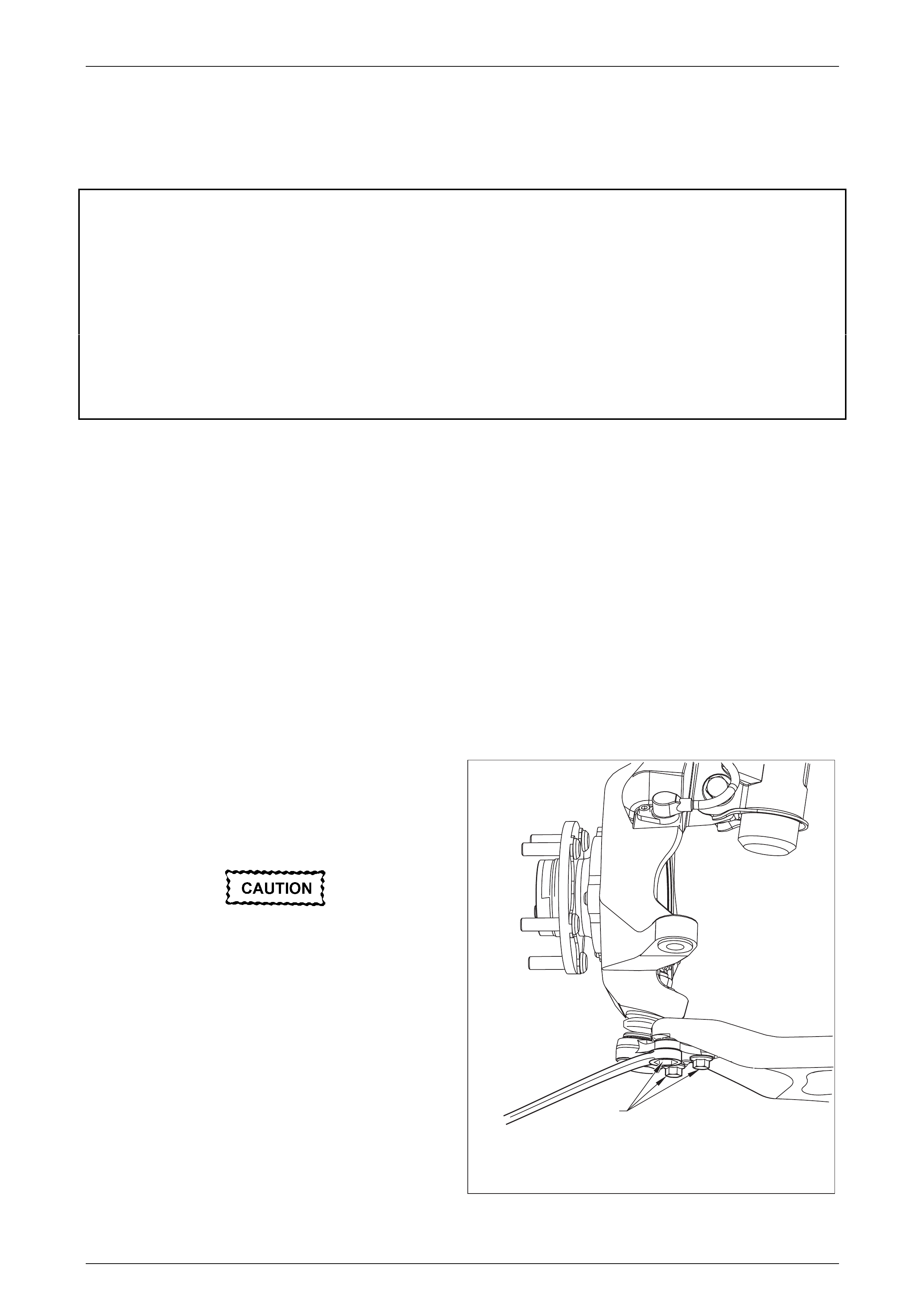
Suspension Page C-36
Page C-36
3.10 Front Control Arm
LT Section No. – 06-200
ATTENTION
The following fasteners have either micro encapsulation or incorporate a mechanical thread lock and should
only be used once. If in doubt, replacement is recommended when performing these operations:
Front control arm ball joint stud nut.
The following fasteners MUST be replaced when p erfo rmin g these operations:
Front control arm front isolator and rear bushing retaining bolts.
Before the following fasteners are fully tightened, the vehicle MUST be at curb height:
• Front control arm front isolator and rear bushing retaining bolts.
Remove
1 Observing the jacking precautions, refer to 2.3 Jacking Precautions in this Section, raise the front of the vehicle and
support on safety stands.
2 Remove the decorative wheel nut caps and mark the relationship of the wheel to the hub stud, using a felt tipped
pen or similar.
3 Loosen, then remove the road wheel attaching nuts, working in a 'star' pattern.
Refer to Section 10, Wheels and Tyres in the MY 2003 VY and V2 Series Service Information, for detailed
information. Remove the road wheel.
NOTE
Steps 2 and 3 are necessary to maintain part
relationships and to avoid brake rotor distortion
and the creation of brake shudder, after the
vehicle is placed back in service.
4 Turn the steering out on full lock.
5 Remove 3 bolts (1) Refer Fig 3-43 from ball joint
housing and separate ball joint housing from lower
control arm.
Do not allow the front driveshaft to extend to
the stage w here the in ner tripot end b ecomes
separated. After release of the ball joint,
ensure that the outer end is released from the
wh eel hub and supported by tie wire.
1
Figure 3 – 43
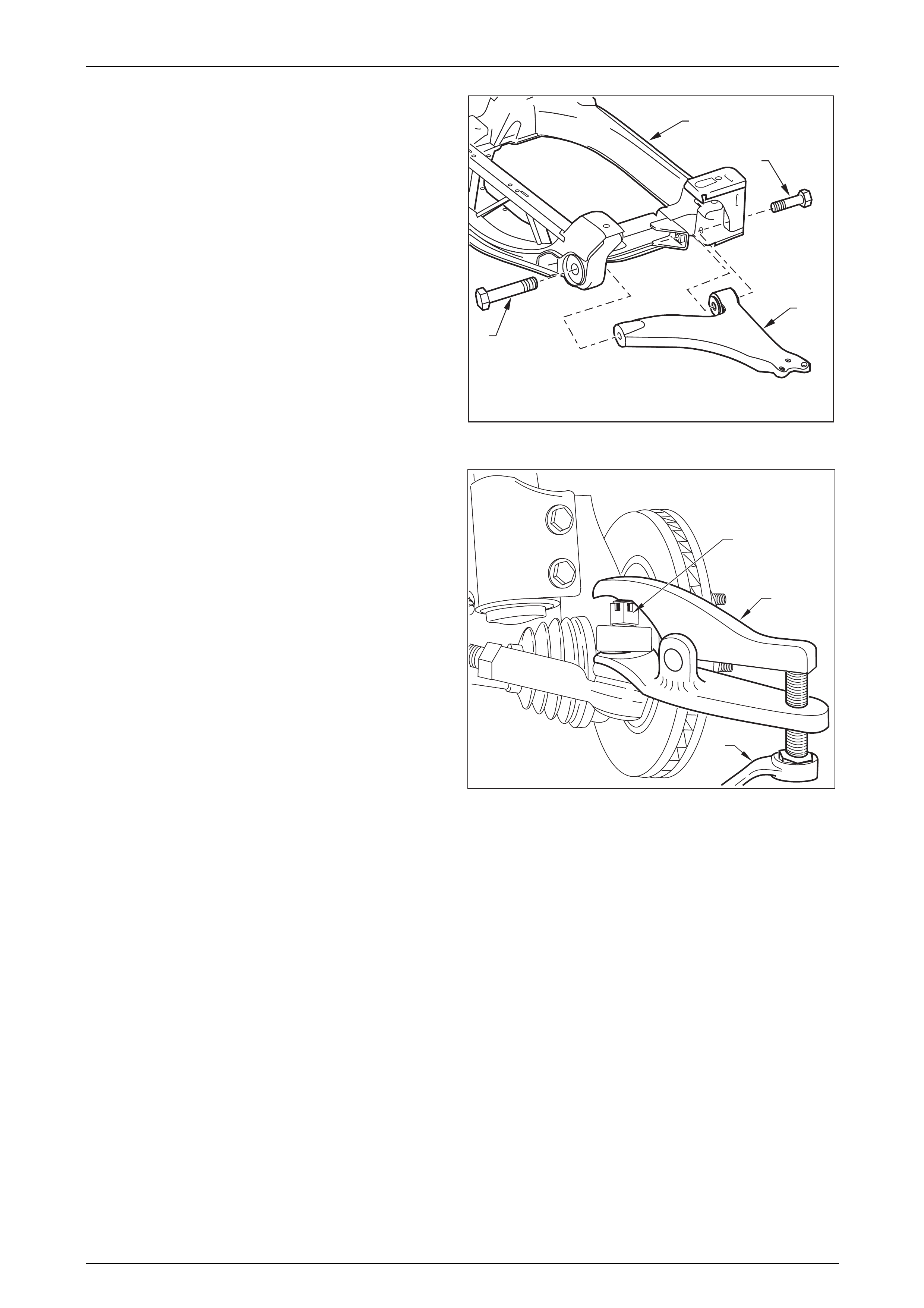
Suspension Page C-37
Page C-37
6 Remove the screws and scrivets securing the front
plastic under tray from the front bumper, then remove
the under tray from the vehicle.
7 Using a 24 mm socket and suitable equipment, loosen
then remove the front control arm front isolator bolt (3),
until several threads remain.
NOTE
Thread sealant on this front bolt may make the
removal effort high. However, under no
circumstances is heat to be applied to the control
arm, in an attempt to soften the sealant.
1
2
3
4
Figure 3 – 44
8 Remove the split pin and loosen the castellated nut (1)
until the nut is flush with the end of the tie rod end
stud.
9 Install Tool No. E9332-A as shown and, using a ring
spanner (2), press the stud out from the steering
knuckle.
10 To gain access to the rear bushing retaining bolt (4),
turn the steering out on full lock and hold in this
position. Allow the tie rod to drop under its own weight.
This will provide enough space to gain access to the
front control arm rear bushing bolt.
2
1
E9332-A
Figure 3 – 45
11 Use a 19 mm socket and suitable equipment, loosen the front control arm rear bushing bolt (4) from the rear but
leave installed to support the rear bushing.
12 While supporting the front control arm, completely remove the front control arm front isolator bolt (3) and the rear
bushing bolt (4), then remove the front control arm (1) from the crossmember cradle.
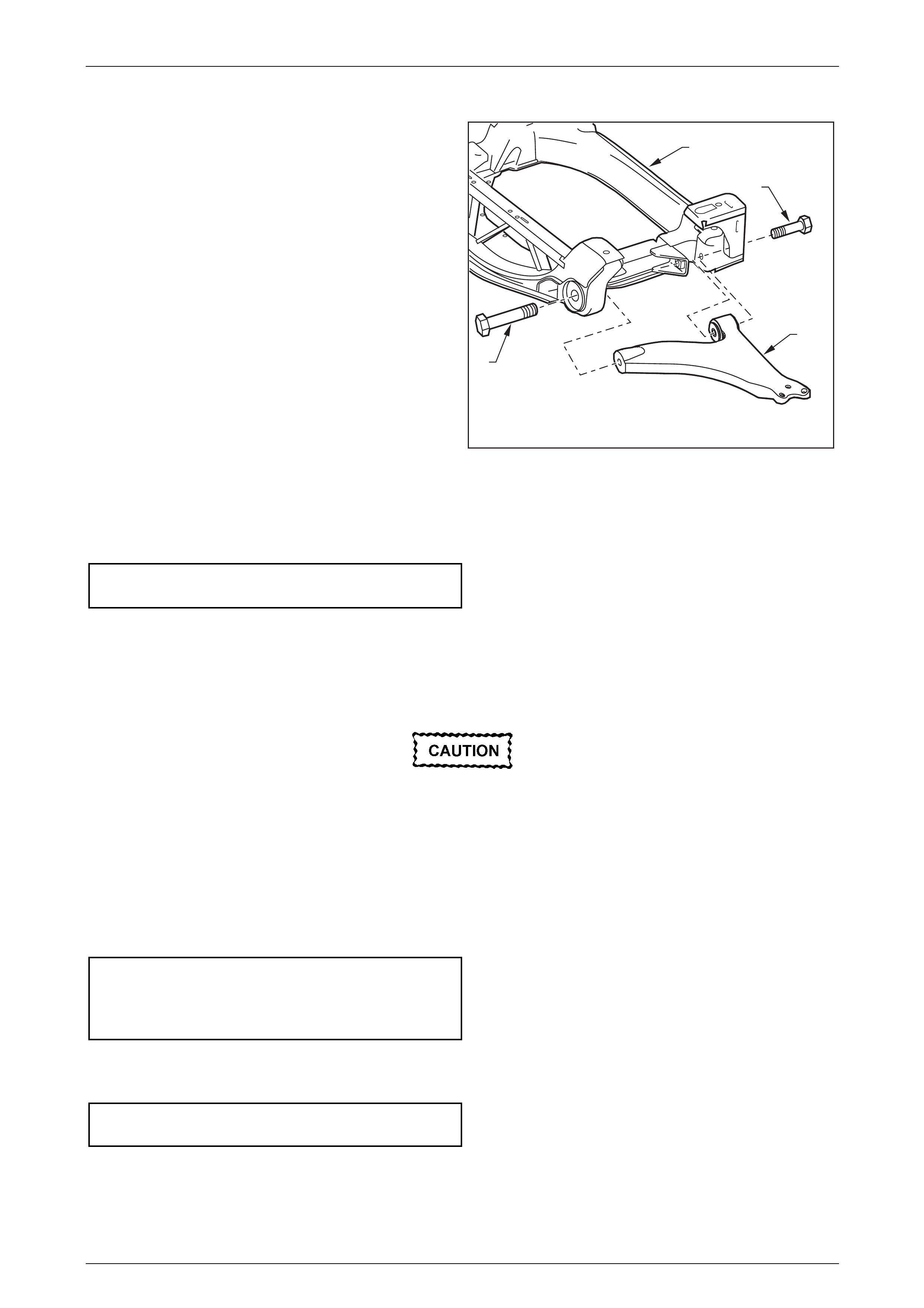
Suspension Page C-38
Page C-38
Reinstall
1 Reinstall the front control arm (1) to the crossmember
cradle (2), then install new front isolator (3) and rear
bushing (4) bolts but do not fully tighten at this stage.
1
2
3
4
Figure 3 – 46
2 Using a suitable floor jack fitted with a block of wood positioned under the front control arm, raise the jack sufficient
to support the weight of the strut assembly and install three ball joint housing bolts.
3 It is recommended that 3 new ball joint housing bolts are fitted to the lower control arm. Tighten the bolts to the
correct torque specification.
( ) Lower control arm ball joint
housing bolt torque specification..........................65 N.m
4 Reinstall the road wheel, aligning marks made prior to removal. Reinstall the wheel nuts but do not fully tighten at
this time.
5 Lower vehicle to the ground.
6 Roll the vehicle back and forth, then bounce the vehicle up and down several times to settle the suspension.
The weight of the vehicle must be on all four
w heels before tightening the front control arm
isolator bolts to specification. Tensioning
these bolts when the insulating bushing is
incorrectly pre-loaded will result in reduced
insulator bushing life and will adversely affect
the ride and handling characteristics of the
vehicle.
7 With the weight of the vehicle on the suspension components, tighten both the front control arm isolator and the
rear bushing bolts to the correct torque specification.
( ) Front control arm front isolator
bolt torque specification .....................................340 N.m
( ) Front control arm rear bushing
bolt torque specification .....................................180 N.m
Straighten the wheels and, with the vehicle on the ground, tighten the road wheel attaching nuts to the correct torque
specification, working in a ‘star’ pattern, refer to 2.3 Wheel Removal and Installation, 10 Wheels and Tyres, in the MY
2003 VY and V2 Series Service Information.
Road wheel attaching nut
torque specification............................................125 N.m
9 Reinstall the front plastic under tray to the front bumper and front suspension cradle, securing with the screws, self
tapping screws and scrivets.
10 Reinstall the decorative wheel nut caps.
11 Check the wheel alignment, refer to 2.2 Wheel Alignment Checking and Adjustment in this Section.
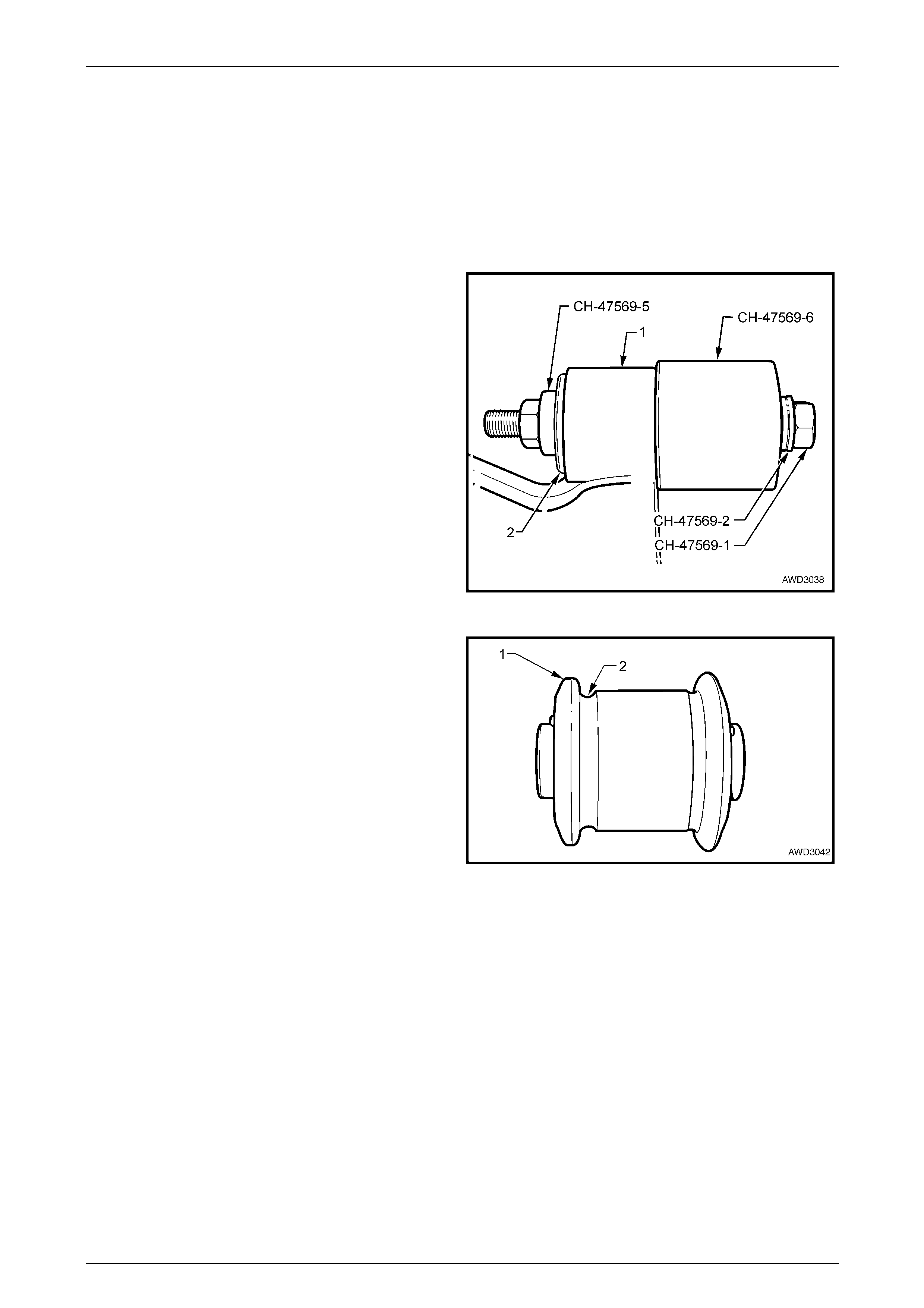
Suspension Page C-39
Page C-39
3.11 Front Control Arm Rear Bushing
LT Section No. – 06-200
Replace
1 Remove the front control arm (1), refer to 3.10 Front Control Arm in this Section.
2 Secure the front control arm in a vice fitted with soft jaws.
3 Install the removal tool with the thrust bearing CH-
47569-2 under the bolt head CH-47569-1, then insert
the receiver cup CH-47569-6. With this sub-assembly
inserted through the bush to be removed, install the
smaller cupped piece, CH-47569-5 over the bolt and
secure with a nut and flat washer.
4 While holding the nut, turn the bolt head to force the
bushing (2) into the receiving cup, Tool No. CH-47569-
6.
5 After bush removal, check the bore of the control arm
(1) for damage or rust. Clean up as required.
Figure 3 – 47
6 Apply a soap solution or petroleum jelly (e.g.
Vaseline ™) to the bore of the control arm and to the
smaller flange (1) of the new bushing.
NOTE
Apart from the smaller diameter of the inboard
end of the bushing, this is also the end with the
larger groove (2) that allows greater bush flange
distortion during the installation process.
Figure 3 – 48
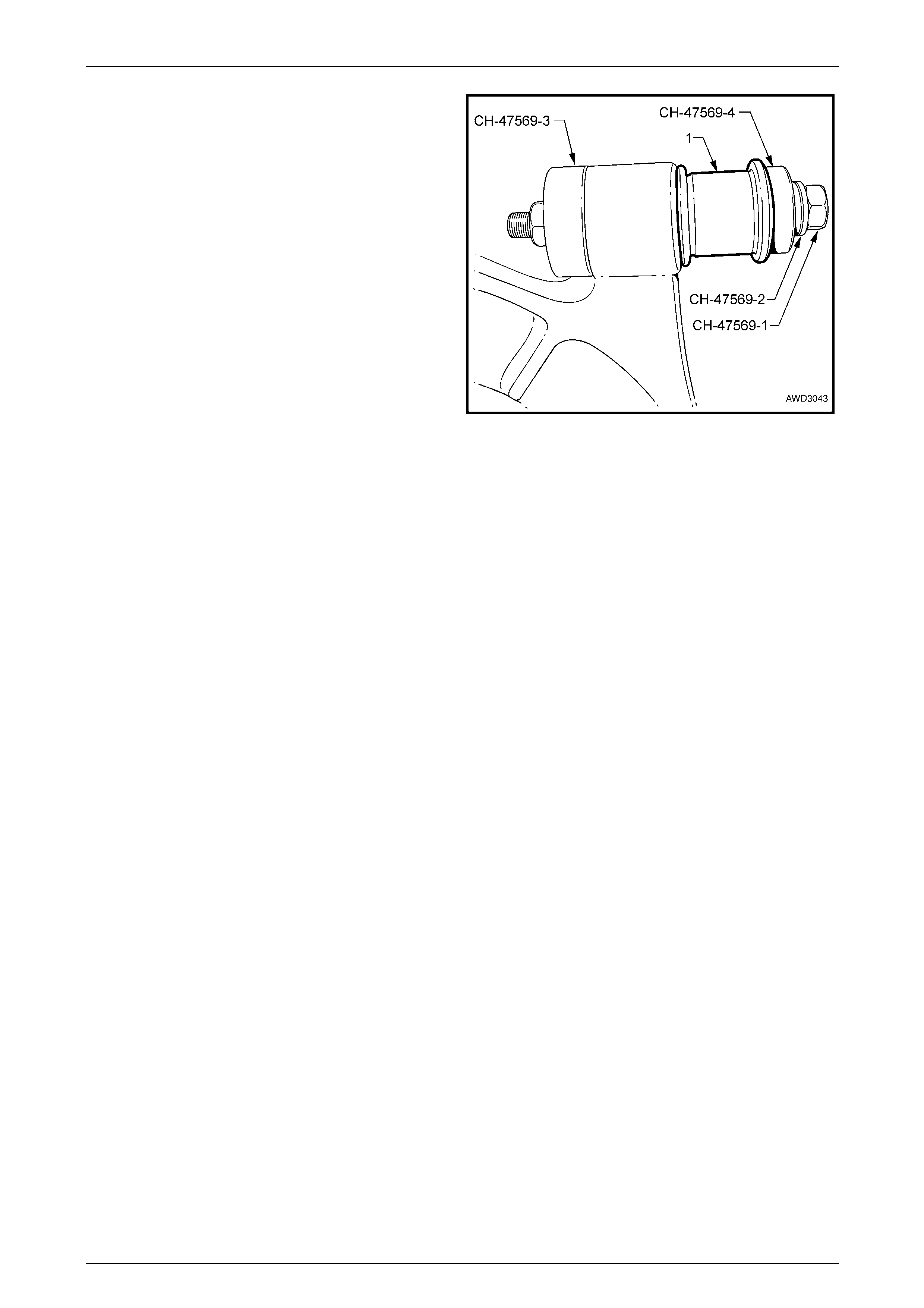
Suspension Page C-40
Page C-40
7 Assemble the installation tools with the thrust bearing
CH-47569-2 under the bolt head CH-47569-1, followed
by the larger of the two cups, CH-47569-4, then the
lubricated bush (1). Install the receiver cup CH-47569-
3 over the inserted bolt, then secure with the flat
washer and nut.
8 To install the new bush, proceed as follows:
a While holding the nut, slowly turn the bolt head to
compress the bush.
b With the bush compressed, wait until the bush
land distorts and starts to enter the control arm,
before proceeding.
c Continue to turn the bolt head until the bush is
fully installed.
d Remove the installation tools and check that the
bush is centrally located on each side of the
control arm.
NOTE
If the bush has been installed too far, assemble
the tools in the removal position and centralise
the bush. Refer to Figure 3-49 for the tool setup.
9 Reinstall the front control arm, refer to
3.10 Front Control Arm, in this Section.
Figure 3 – 49
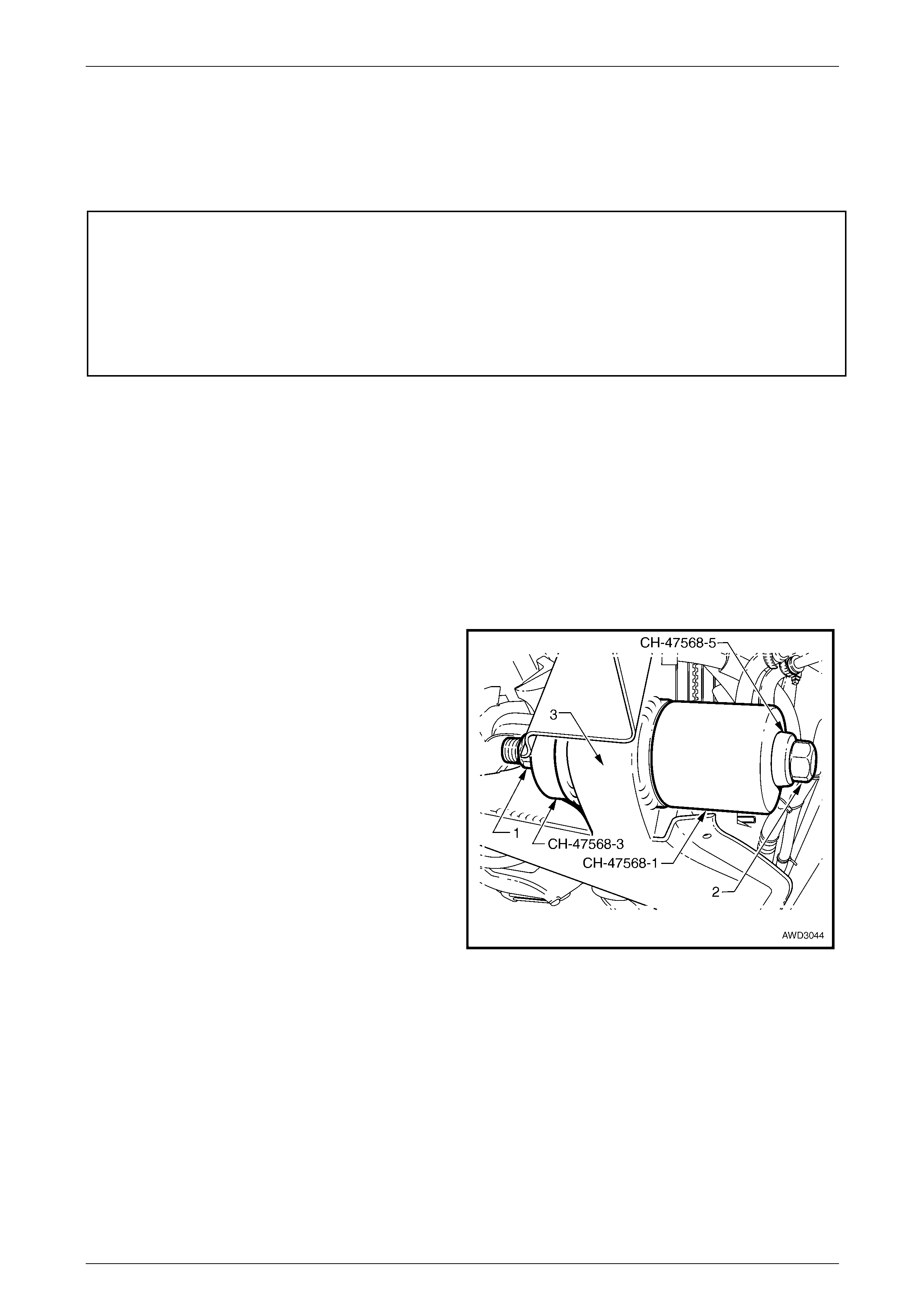
Suspension Page C-41
Page C-41
3.12 Front Control Arm Front Isolating
Bushing
LT Section No. – 06-200
ATTENTION
The following fasteners MUST be replaced when p erfo rmin g these operations:
Front control arm, front isolator and rear bushing retaining bolts.
The following fasteners MUST be at curb height before final tightening:
• Front control arm, front isolator and rear bushing retaining bolts.
Inspect
The front control arm, front isolating bushing is a hydraulically dampened component. Visible splits in the bushing do not
necessarily mean that the bush has failed. The bush may also appear to be 'off-centre' when the vehicle is standing
stationary but this is a normal condition.
The main criteria that indicates that the bushing has failed, is the indication or presence of hydraulic fluid leaking from the
bushing. Therefore, only if fluid is observed to be leaking from the bushing, is it to be replaced, by following the procedure
detailed in this service operation.
Replace
1 Remove the front control arm. Refer to 3.10 Front Control Arm, in this Section.
2 Install Tool No. CH-47568 to the front isolating bush to
be replaced, as shown in Figure 3-52.
NOTE
The receiving cup (CH-47568-1), forcing screw
(2) and thrust race (CH-47568-5) are installed
from front to rear.
3 While holding the nut (1), use suitable socket
equipment to tighten the forcing screw (2) of Tool No.
CH-47568, to remove the isolating bush from the front
suspension crossmember cradle (3), into the receiver,
CH-47568-1. Discard the removed bush.
Figure 3 – 50
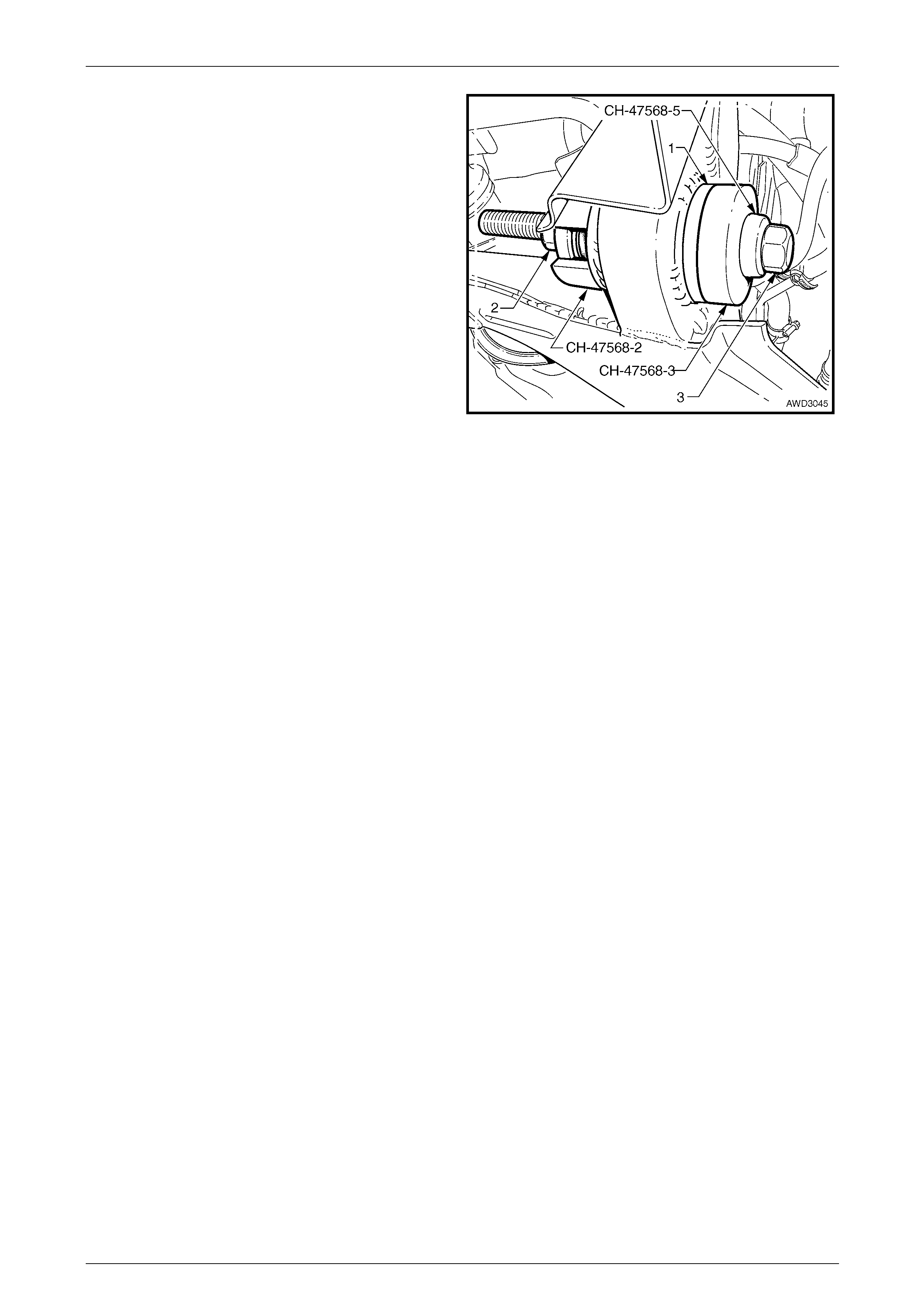
Suspension Page C-42
Page C-42
4 Lightly lubricate the outer steel sleeve (1) of a new
isolating bush, with a light coating of molybdenum
disulphide grease.
NOTE
Ensure that the voids in the bush are aligned
correctly, as shown in Figure 3-55.
5 Assemble the forcing screw (3), thrust bearing CH-
47568-5 and installing cup CH-47568-3, into the new
isolating bush, then install into the front suspension
crossmember cradle, working from front to rear.
NOTE
Arrange the slot in cup, Tool No. CH-47568-2, so
a measurement can be taken from the rear of the
isolating bush, inner flange. Refer to Step 7.
6 While holding the nut of the forcing screw of Tool CH-
47568, turn the bolt head to push the front isolating
bush into the crossmember cradle. Figure 3 – 51
7 The correct positioning of the bush is assessed by measuring the distance from the inner flange of the front
isolating bush (1), to the rear land (2) for the rear bush in the front crossmember cradle (3), which is to be from
337.1 to 337.6 mm.
NOTE
If the bush is installed too far, it will not be
possible to reinstall the control arm. Therefore, it
will be necessary to extract the isolating bush,
until the required dimension is achieved. Refer to
Figure 3-52 for the tool arrangement.
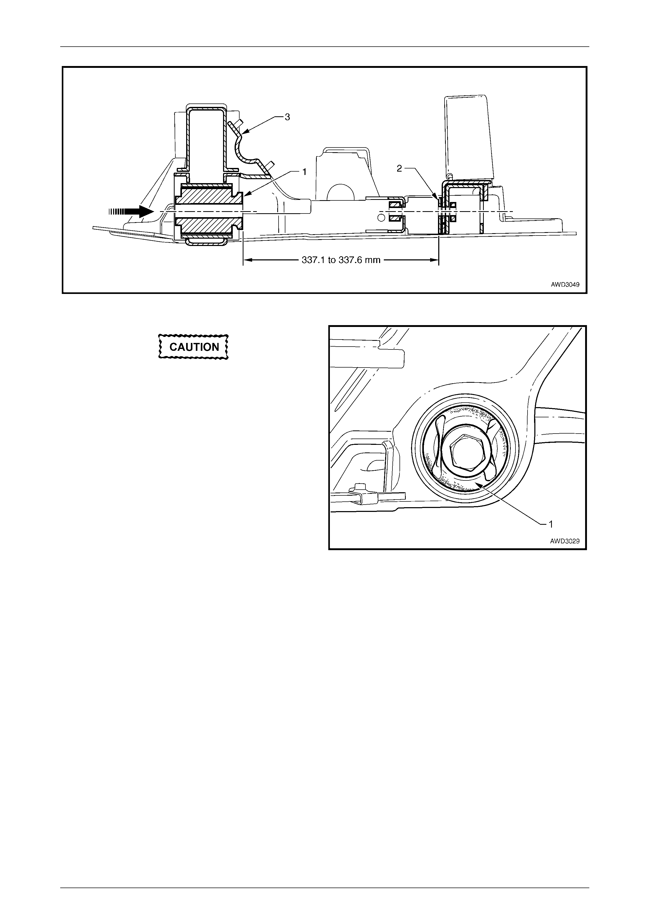
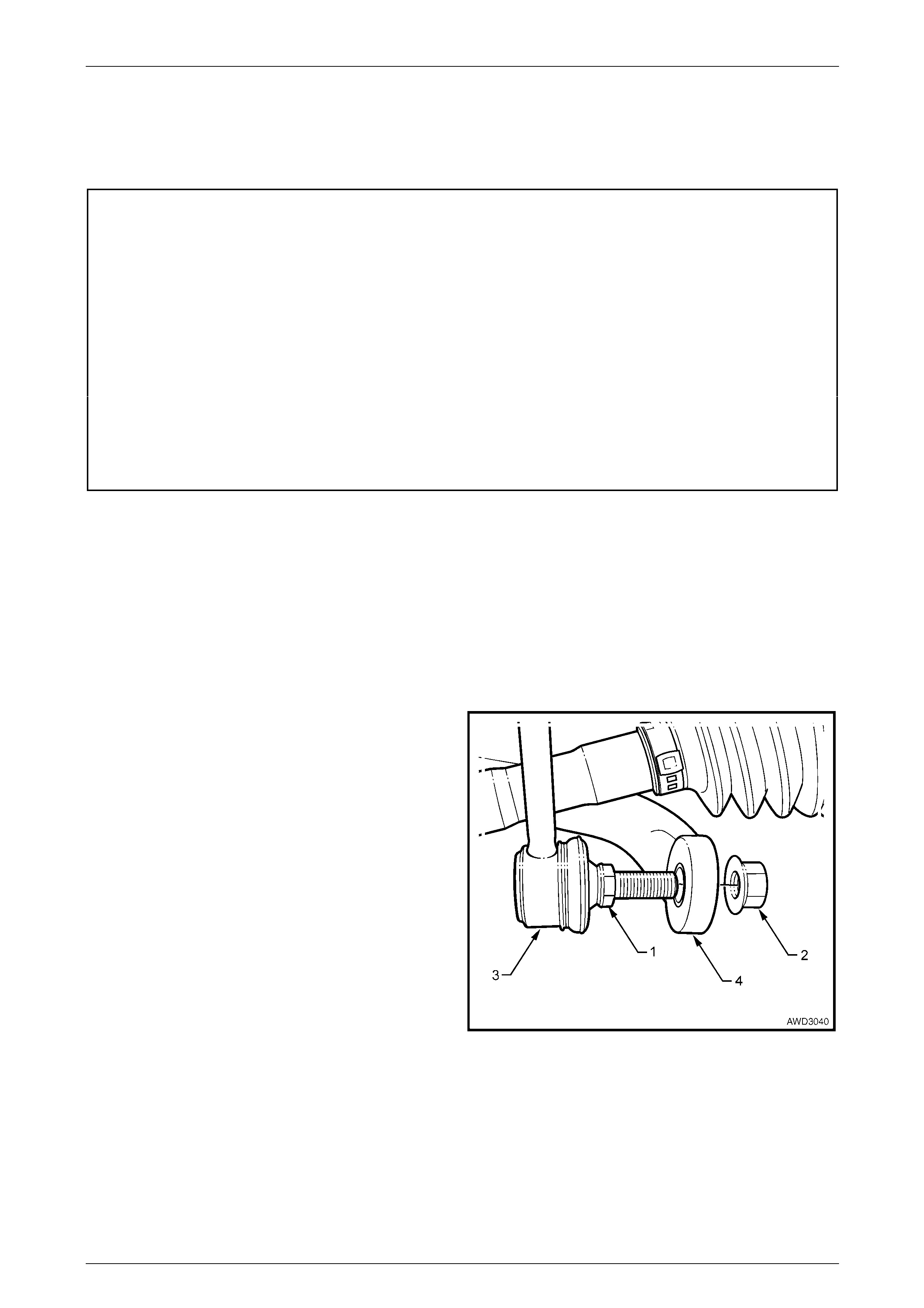
Suspension Page C-44
Page C-44
3.13 Front Suspension Crossmember Cradle
LT Section No. – 06-200
ATTENTION
The following fasteners MUST be replaced when p erfo rmin g these operations:
Steering rack housing to crossmember cradle bolts and nuts.
Lower control arm ball joint housing to lower control arm bolts.
Front suspensio n crossmember cradle to side member attaching bolt.
Front control arm to crossmember cradle front isolating and rear bushing bolts.
Engine mount to crossmember cradle attaching nuts.
The following fasteners MUST be at curb height before final tightening:
Front control arm to crossmember cradle front isolating and rear bushing bolts.
Remove
1 Observing the jacking precautions, refer to 2.3 Jacking Precautions in this Section, raise the front of vehicle and
place safety stands under the side frame members.
2 Remove the decorative wheel nut caps.
3 Mark the relationship of each road wheel to its hub and rotor. Loosen, then remove the road wheel attaching nuts.
Remove the road wheels. Do not mix from side to side.
4 Remove the screws and scrivets securing the front plastic under tray from the front bumper and front suspension
cradle, then remove the under tray from the vehicle.
5 With a backing set spanner holding the stabiliser bar
link inner stud hexagon (1), use a second spanner to
loosen then remove the retaining nut (2).
6 Separate the stabiliser bar link (3) from the stabiliser
bar (4).
7 Repeat steps 4 and 5 for the other side.
Figure 3 – 54
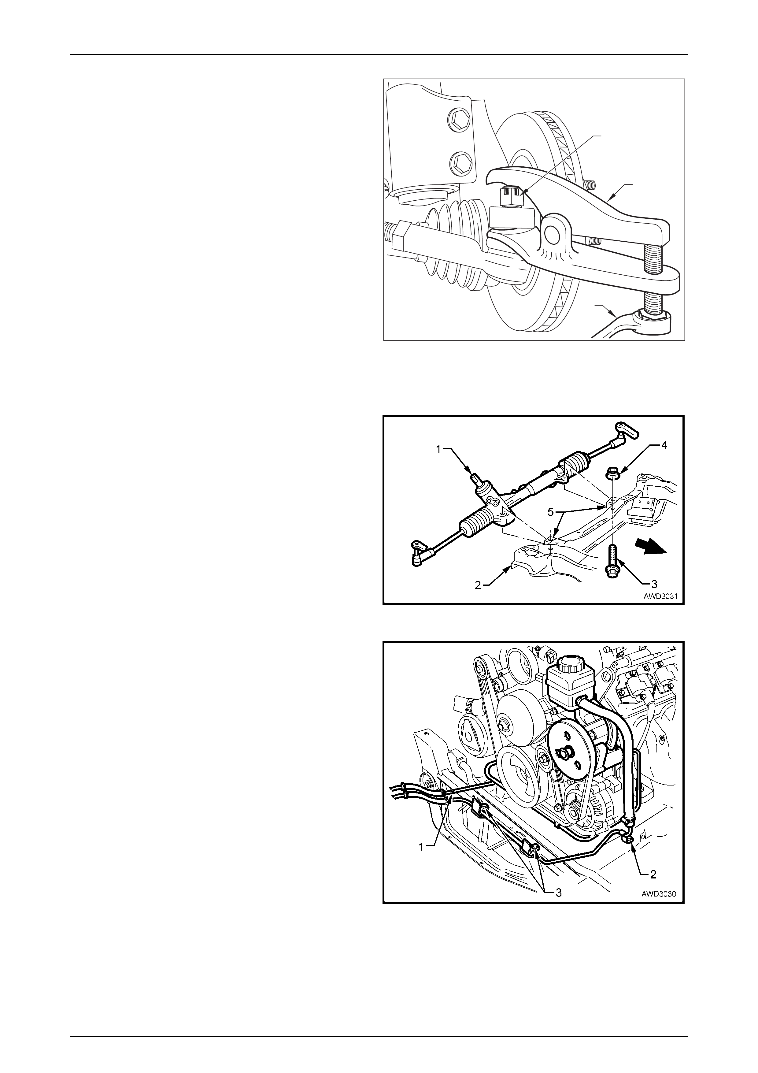
Suspension Page C-45
Page C-45
8 Remove the split pin from the steering linkage outer tie
rod end castellated nut (1), then loosen the nut until
the top of the nut is level with the top of the steering
linkage outer tie rod socket stud.
9 Install Tool No. E9332-A and use a ring spanner (2) to
separate the steering linkage outer tie rod socket stud
from the steering knuckle.
10 Repeat steps 6 and 7 for the other side.
2
1
E9332-A
Figure 3 – 55
11 Remove the air chute to crossmember securing screws. Refer to Section 6B3 Engine Cooling – GEN III V8 in the
MY 2004 AWD Wagon Service Information, for locations.
12 Remove the steering gear housing (1) to front
crossmember cradle (2) mounting bolts (3) and nuts
(4).
13 Remove the steering gear housing from the
crossmember mountings (5), then support the rack
with tie wire to convenient points on the vehicle
underbody.
NOTE
Dependent on personal choice but disconnecting
the steering shaft coupling cam bolt and nut will
provide more flexibility with steering rack
movement. The nut however, must be replaced
on reassembly. Figure 3 – 56
14 Remove the screws and brackets securing the power
steering pipes and engine coolant transfer tube to the
front crossmember cradle:
a At the right (1) and left (2) side rails.
b In two places across the front rail (3).
Figure 3 – 57
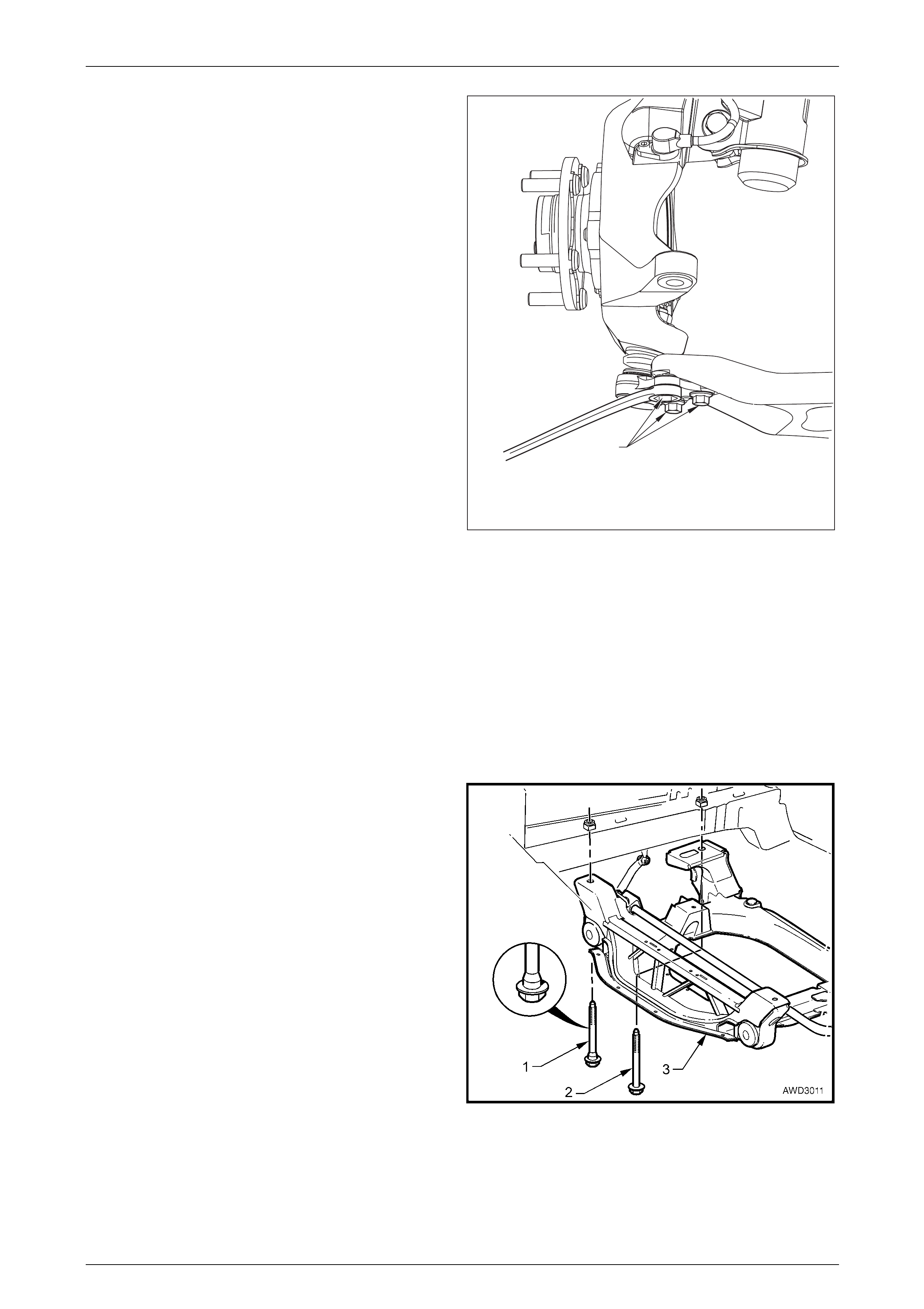
Suspension Page C-46
Page C-46
15 Turn each wheel out in turn.
16 Remove 3 ball joint housing bolts (1) and swing
knuckle and strut assembly out of the way
1
Figure 3 – 58
17 Remove each of the front driveshafts from the vehicle.
Refer to Section 4B2 Front Final Drive, Bearing Housing & Driveshafts in the MY 2004 AWD Wagon Service
Information, for the procedure.
18 Use a suitable length wooden prop, support the steering knuckle, disc, front hub and strut against the side rail.
Repeat for the other side of the vehicle.
19 Disconnect the windscreen washer tubing, mark the engine hood hinge positions then remove the engine hood.
20 Support the engine with a suitable lifting device, then remove the front engine mount to crossmember cradle nuts
from under the vehicle, using an 18 mm deep socket and suitable socket equipment.
21 Support the crossmember cradle (3) on a jack and
suitable pieces of wood, then remove the four bolts (1
and 2) securing the crossmember cradle to the side
frame members.
NOTE
If working from a hoist, use a commercially
available, hydraulic scissor lift, mobile bench to
support the crossmember.
22 Lower, then remove the crossmember cradle
assembly (3) from vehicle.
23 As required, remove the front control arms, front
control arm rear bushings, front isolating bushes and
stabiliser bar from the crossmember. Refer to;
3.10 Front Control Arm
3.11 Front Control Arm Rear Bushing
3.12 Front Control Arm Front Isolating Bushing
3.16 Stabiliser Bar
Figure 3 – 59
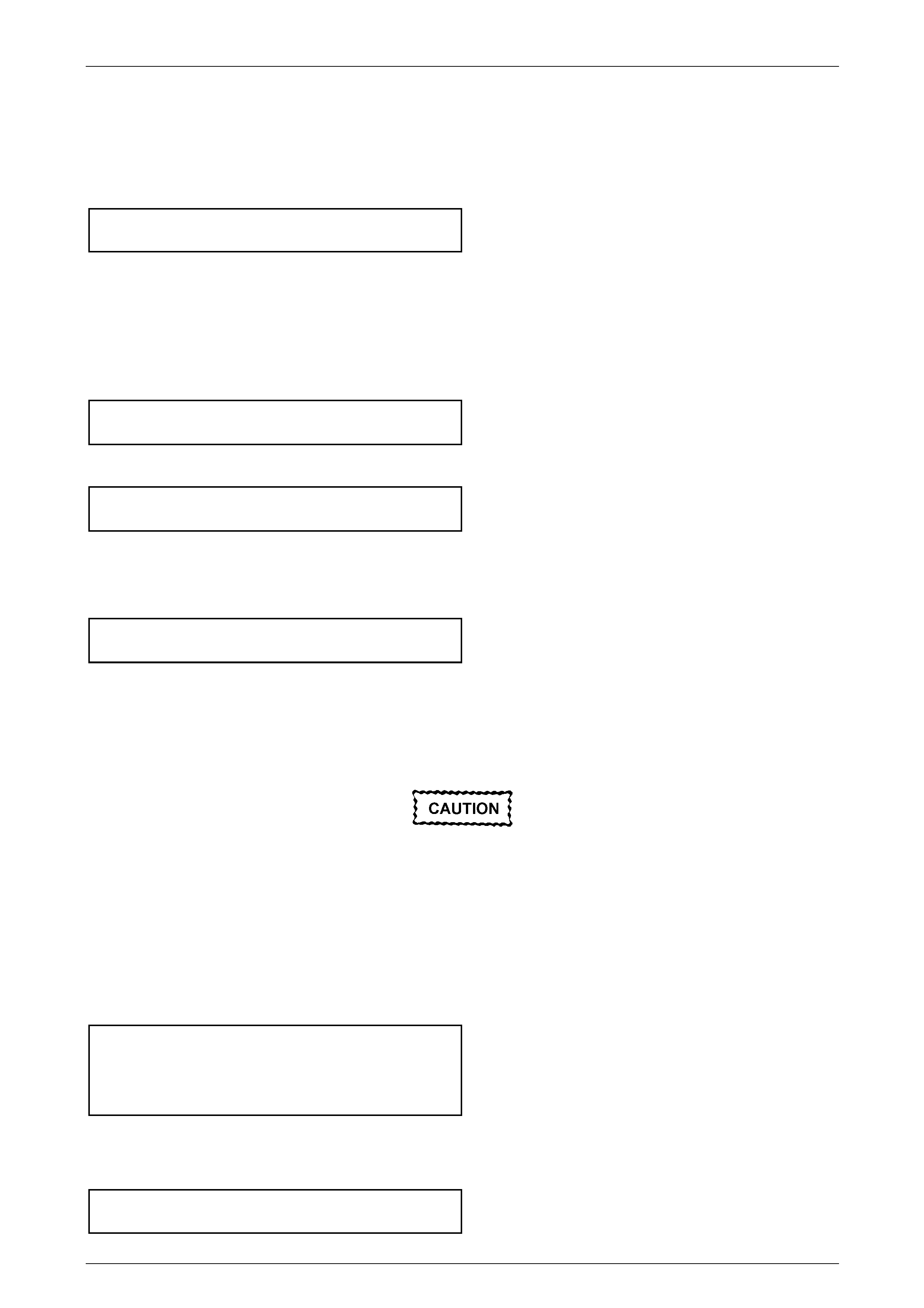
Suspension Page C-47
Page C-47
Reinstall
While the majority of the reinstallation process is the reverse of the removal procedures, note the following points:
1 If removed, reinstall the stabiliser bar insulating rubbers and brackets onto the crossmember cradle, refer to
3.16 Stabiliser Bar. Tighten the retaining nuts to the correct torque specification.
Stabiliser bar bushing bracket
nut torque specification........................................28 N.m
2 Reinstall the two front control arms to the crossmember cradle, installing new, front isolating and rear bushing bolts
but do not fully tighten at this stage.
3 After raising the crossmember cradle, install two NEW front, stepped bolts (‘1’ in Figure 3-61). This will correctly
align the crossmember to the side frames.
4 Install two NEW rear, plain shanked bolts (‘2’ in Figure 3-61) to the two rear positions and tighten all four bolts to
the correct torque specification.
( ) Crossmember cradle to side
frame bolt torque specification...........................122 N.m
5 Connect the lower control arm to ball joint housing using new bolts and torque to required specification
( ) Front control arm to ball joint
housing bolts........................................................55 N.m
6 Lower the engine to engage the engine mount pins with the holes provided in the crossmember cradle supports.
7 Install new engine mounting nuts, then use an 18 mm deep socket and torque wrench to tighten the nuts to the
correct torque specification.
( ) Front engine mount attaching
nut torque specification........................................80 N.m
8 Reinstall the road wheels, aligning marks made prior to removal.
9 Reinstall the engine hood.
10 Lower the vehicle to the ground, roll the vehicle back and forth about 1 metre in each direction, then bounce the
vehicle several times to settle the suspension.
The weight of the vehicle must be on all four
w heels before tightening the front control arm
isolator and bushing bolts to specification. If
not, the bushings will be stressed with the
vehicle at rest and the bushings will fail
prematurely w hen the vehicle is put back into
service.
11 With the weight of the vehicle on the suspension components, tighten all front control arm isolator and rear bushing
bolts to the correct torque specification.
( ) Front control arm, front isolator
bush bolt torque specification.............................340 N.m
( ) Front control arm, rear bushing
bolt torque specification .....................................180 N.m
12 Tighten the road wheel attaching nuts to the correct torque specification, working in a ‘star’ pattern.
Refer to Section 10, Wheels and Tyres in the MY 2003 VY and V2 Series Service Information. Reinstall the
decorative wheel nut caps.
Road wheel attaching
nut torque specification......................................125 N.m

Suspension Page C-48
Page C-48
13 Install the steering gear housing to the crossmember cradle and tighten NEW mounting nuts and bolts. Hold the
nuts and tighten the bolts to the correct torque specification.
( ) Steering rack housing to
crossmember mounting bolt
torque specification................................... 60 N.m, then
...............................................................turn through 50°
14 If the power steering flare pipes were disconnected during the removal process, remove plugs from the power
steering hydraulic pipes and valve housing apertures, then reinstall the pipes. Tighten each flare nut to the correct
torque specification.
Hydraulic pipe to steering rack
valve housing flare nut
torque specification..............................................35 N.m
15 Bleed the power steering hydraulic system. Refer to Section 9 Steering, in the MY 2003 VY and V2 Series Service
Information.
16 Reinstall the front plastic under tray to the front bumper and front suspension cradle, securing with the screws, self
tapping screws and scrivets.
17 Reinstall the decorative wheel nut caps.
18 Check the wheel alignment, refer to 2.2 Wheel Alignment Checking and Adjustment in this Section.
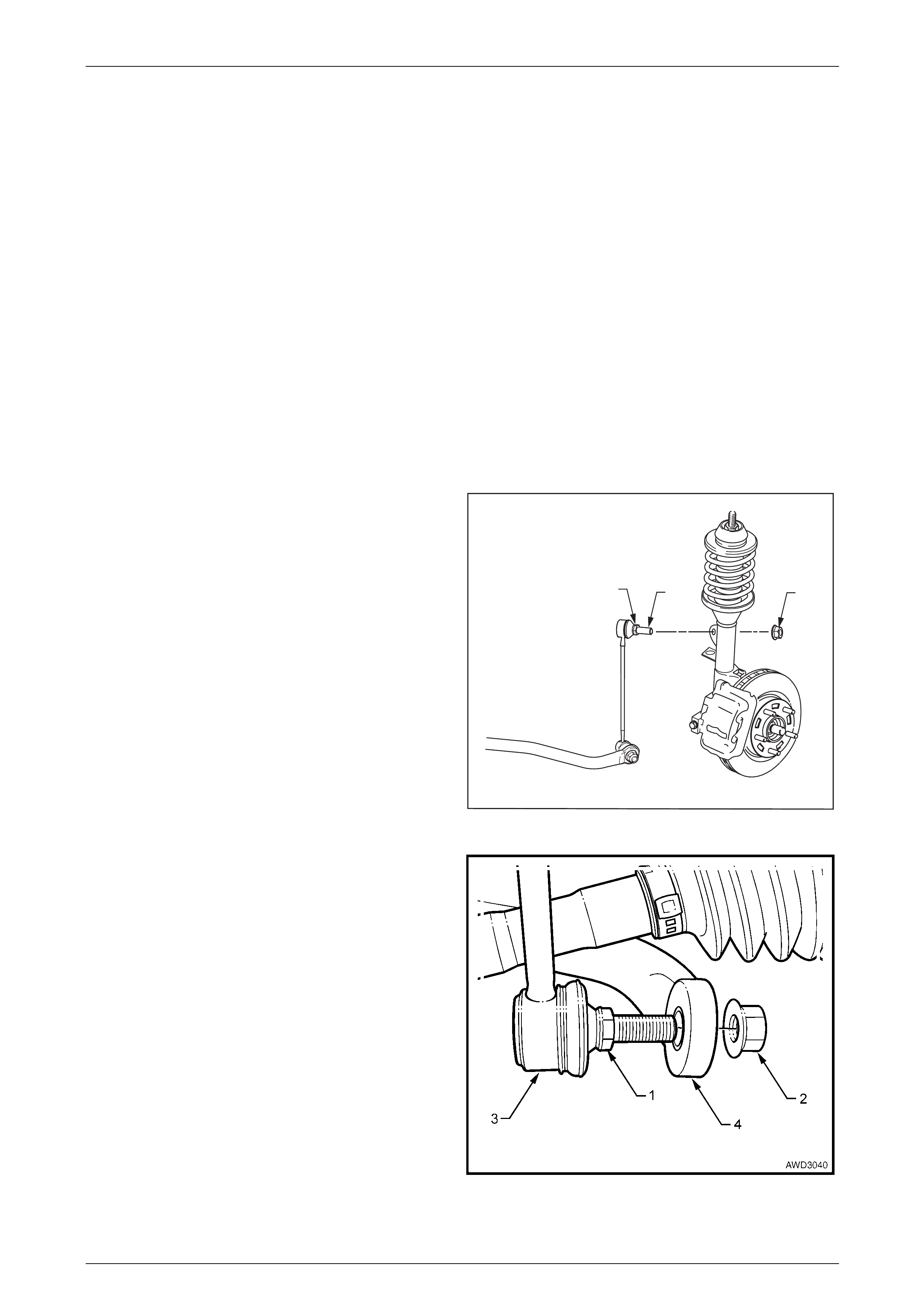
Suspension Page C-49
Page C-49
3.14 Stabiliser Bar Link
LT Section No. – 06-205
Replace
1 Raise the front of the vehicle and place safety stands under side frame members.
Refer to 2.3 Jacking Precautions in this Section.
2 Remove the decorative wheel nut caps on the side where this procedure is to be carried out.
3 Mark the relationship of the wheel to the hub and brake rotor, then loosen and remove the road wheel attaching
nuts and remove the road wheel. Refer to Section 10, Wheels and Tyres in the MY 2003 VY and V2 Series Service
Information.
NOTE
Step 3 is necessary to maintain component
relationships and to avoid brake rotor distortion
with the resultant creation of brake shudder, after
the vehicle is placed back in service.
4 Using a suitable size spanner, hold the stabiliser bar
socket stud (1) at ‘A’, then use another spanner to
loosen and remove the stabiliser bar spacer stud nut
(2).
12
A
Figure 3 – 60
5 Separate the stabiliser bar link (3) from the stabiliser
bar (4) and remove from the strut mounting bracket.
Figure 3 – 61
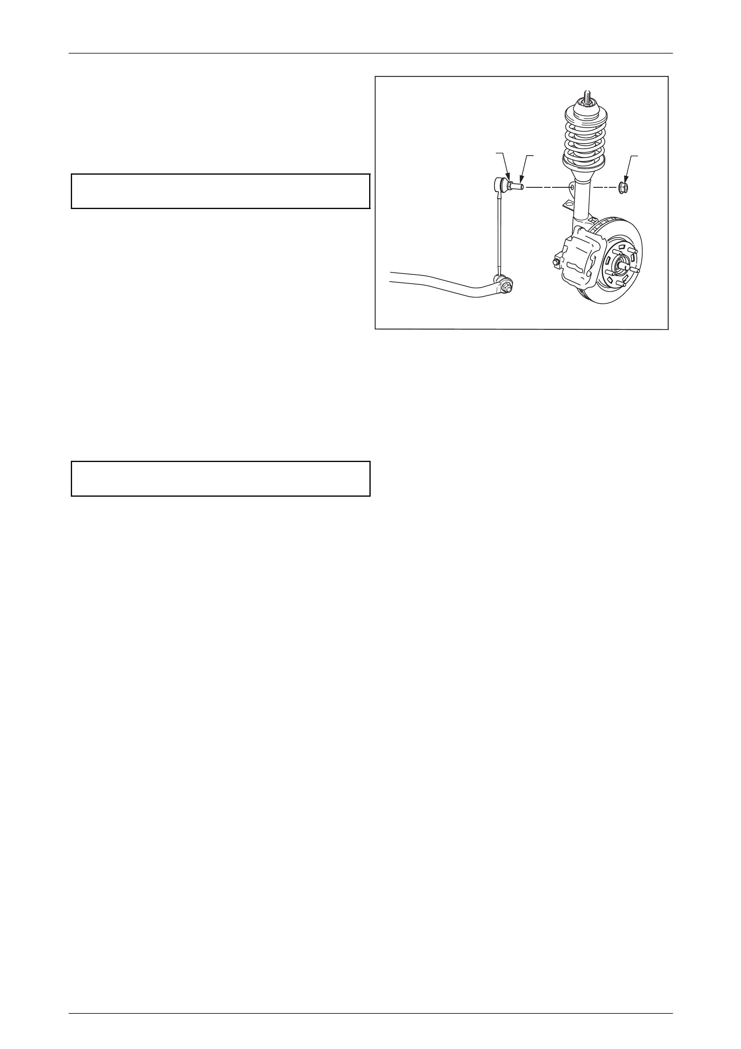
Suspension Page C-50
Page C-50
The installation procedure is the reverse to removal, except
for the following points:
6 Reinstall the link ball socket stud to the stabiliser bar
(4), tighten the retaining nut (5) to the correct torque
specification, while holding the inner stud hexagon with
a spanner ('1' in Figure 3-62).
Stabiliser bar link ball socket retaining
nut torque specification........................................50 N.m
7 Reinstall the link ball socket stud to the strut and
tighten the retaining nut (2) to the correct torque
specification, while holding the inner stud hexagon with
a spanner ('1' in Figure 3-62).
12
A
Figure 3 – 62
8 Reinstall the road wheels, aligning the marks made prior to removal, and secure with the wheel attaching nuts, but
do not fully tighten at this stage.
9 Remove the safety stands and lower the vehicle.
10 Tighten the road wheel attaching nuts to the correct torque specification, working in a ‘star’ pattern.
Refer to Section 10 Wheels and Tyres, in the MY 2003 VY and V2 Series Service Information.
Road wheel attaching nut
torque specification............................................125 N.m
11 Reinstall the decorative wheel nut caps.
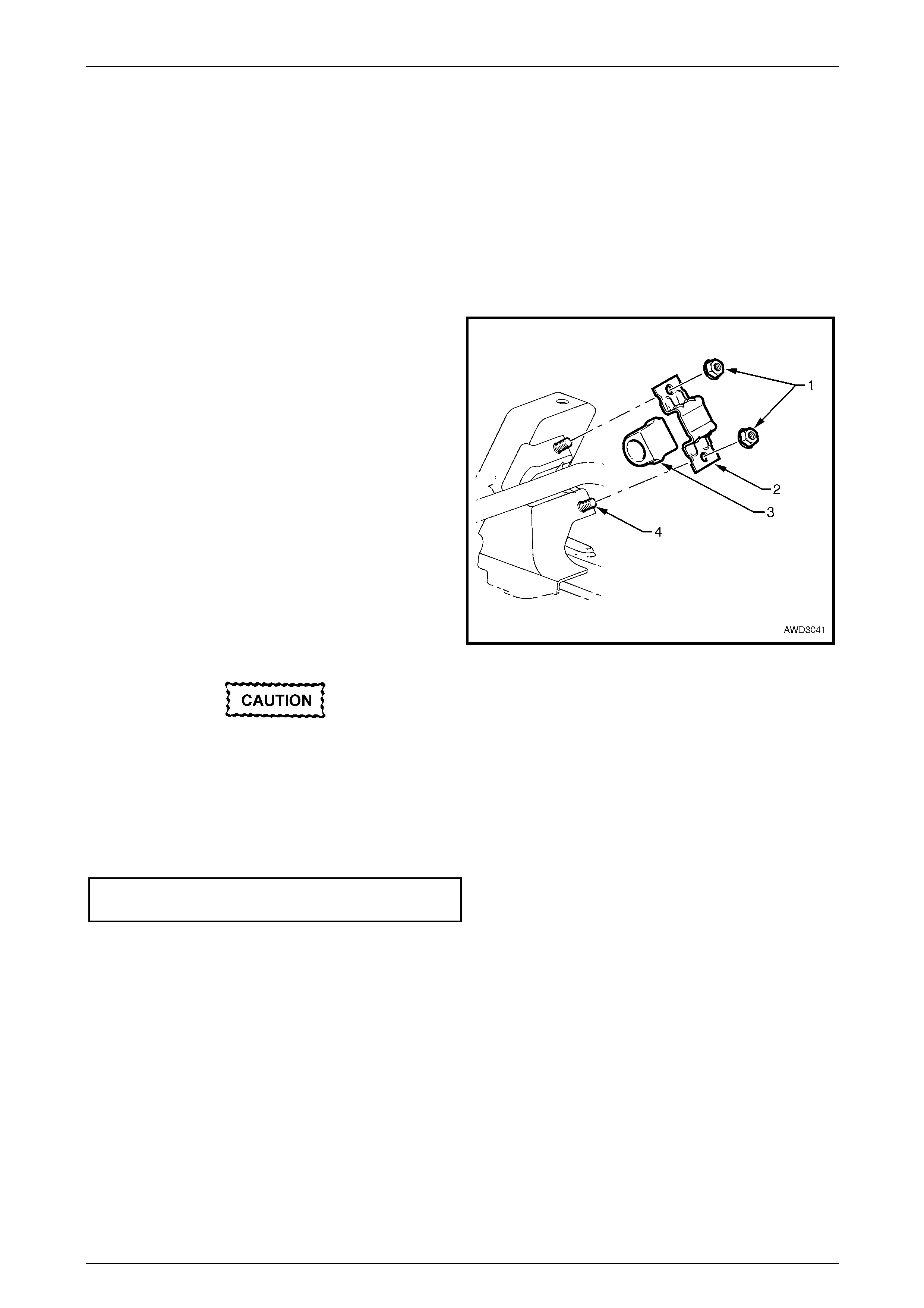
Suspension Page C-51
Page C-51
3.15 Stabiliser Bar Isolator Bushes
Replace
1 Raise the vehicle and support in a safe manner. Refer to 2.3 Jacking Precautions in this Section.
NOTE
Access to the stabiliser bar isolator bushing/s is
made easier by turning the wheels out on the side
being worked on.
2 Using suitable socket equipment, remove the two nuts
(1), securing the insulator bracket (2) to the
crossmember cradle (4). Repeat for the second side.
NOTE
Both sides need to be released to allow removal
of the bushing/s (3) from the crossmember
cradle.
3 Lift the stabiliser bar free from the crossmember
cradle, then remove the bushing/s (3).
4 Reinstall new bushing/s, taking note of the orientation,
reinstall the bracket/s, washers and nuts.
NOTE
The slot in each insulator should face forward,
and the rounded sections on the insulators
should seat in the mating recesses in the
crossmember cradle.
Ensure the stabiliser bar is centralised in the
bushings and brackets. If not corrected,
contact between the stabiliser bar and the
driveshaft outer grease boot may occur on
full suspension hang and/or on full steering
lock.
5 Tighten the nuts to the correct torque specification.
Stabiliser bar bushing bracket
nut torque specification........................................28 N.m
6 Remove safety supports and lower vehicle to the
ground.
Figure 3 – 63
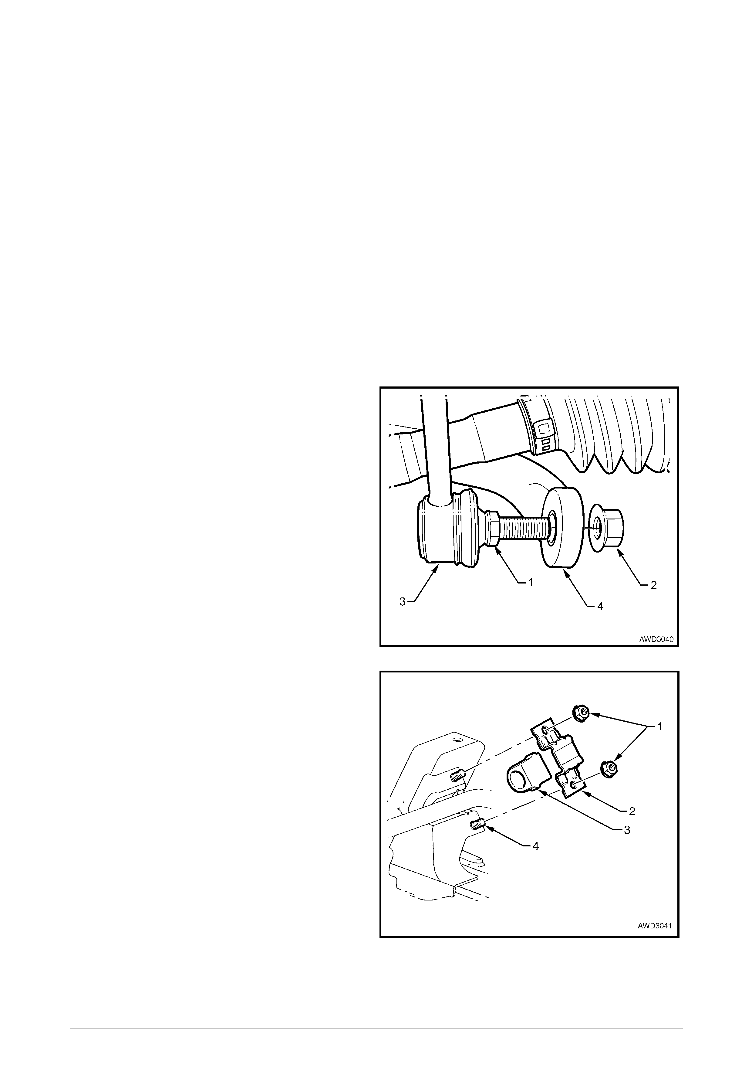
Suspension Page C-52
Page C-52
3.16 Stabiliser Bar
LT Section No. – 06-205
NOTE
To remove the stabiliser bar completely from the vehicle, it will first be necessary to lower the crossmember cradle to
provide the required space. Refer to 3.13 Front Suspension Crossmember Cradle in this Section.
Remove
1 Raise the front of the vehicle and support in a safe manner. Refer to 2.3 Jacking Precautions in this Section.
2 Remove the decorative wheel nut caps on both sides.
3 Mark the relationship of each wheel to its hub and brake rotor, then loosen and remove each of the road wheel
attaching nuts, then remove the road wheels. Refer to Section 10, Wheels and Tyres in the MY 2003 VY and V2
Series Service Information. NOTE
Step 3 is necessary to maintain component
relationships and to avoid brake rotor distortion
with the resultant creation of brake shudder, after
the vehicle is placed back in service.
4 With a set spanner holding the stabiliser bar link inner
stud hexagon (1), use a second spanner to loosen
then remove the retaining nut (2).
5 Separate the stabiliser bar link (3) from the stabiliser
bar (4).
6 Support the engine/transmission assembly, then lower
the crossmember cradle, enough to provide space for
the stabiliser bar removal.
Refer to 3.13 Front Suspension Crossmember Cradle,
in this Section.
Figure 3 – 64
7 Remove the nuts (1) securing the insulator bracket (2)
to each side of the crossmember cradle (4), then
remove the support brackets, stabiliser bar, and
insulators (3) from the crossmember cradle.
8 Remove the stabiliser bar from the vehicle.
Figure 3 – 65
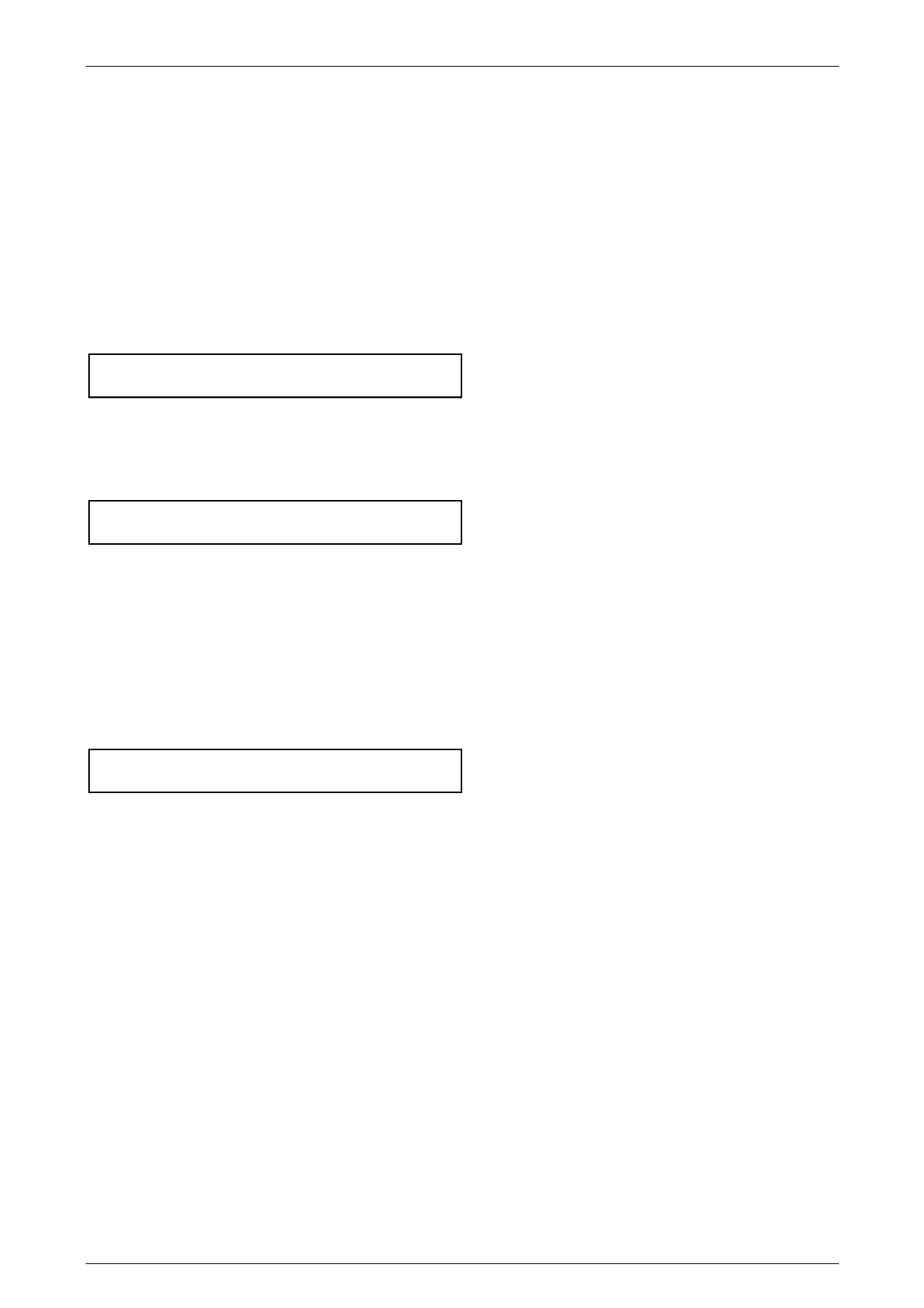
Suspension Page C-53
Page C-53
Reinstall
The reinstallation procedure of the stabiliser bar is the reverse of the removal procedure, except for the following:
1 Reassemble the two insulators onto the stabiliser bar, then reinstall to the crossmember cradle tower.
NOTE
The slot in each insulator should face forward,
and the rounded sections on the insulators should
seat in the mating recesses in the crossmember
cradle.
2 Reinstall both insulator brackets and nuts, then tighten the stabiliser bar insulator bracket nuts to the correct torque
specification.
Stabiliser bar bushing bracket
nut torque specification........................................28 N.m
3 Reinstall the front suspension crossmember cradle. Refer to 3.13 Front Suspension Crossmember Cradle, in this
Section.
4 Reinstall the stabiliser bar link socket stud nut and, while holding the stud hexagon with a set spanner, tighten to
the correct torque specification.
Stabiliser bar link ball stud nut
torque specification..............................................50 N.m
5 Reinstall the road wheels, aligning the marks made prior to removal, and secure with the wheel attaching nuts, but
do not fully tighten at this stage.
6 Remove the safety stands and lower the vehicle.
7 Bounce the vehicle up and down several times to settle the suspension.
8 Check and correct the wheel alignment, as required. Refer to 2.2 Wheel Alignment Checking and Adjustment, in
this Section.
9 Tighten the road wheel attaching nuts to the correct torque specification, working in a ‘star’ pattern.
Refer to Section 10 Wheels and Tyres, in the MY 2003 VY and V2 Series Service Information.
Road wheel attaching nut
torque specification............................................125 N.m
10 Reinstall the decorative wheel nut caps.

Suspension Page C-54
Page C-54
4 Independent Rear Suspension
4.1 General Information
Rear suspension assemblies fitted to HSV models are detailed below these assemblies have been developed to satisfy
the various applications of the range of HSV models described in that paragraph.

Suspension Page C-55
Page C-55
4.2 Rear Axle
The Rear Axle fitted to HSV AWD Coupe 4 models is the same as the Holden Rear Axle. Except for the replacement of
the wheel bearings P/N 92077119, this part has been up rated to P/N 92058075. External dimensions of both parts are
the same. The information in this section is designed to supplement the information contained in the Holden V2 Coupe
service information and details are given where differences occur between the HSV models and standard Holden models.

Suspension Page C-56
Page C-56
4.3 Propeller Shaft And Universal Joints
HSV AWD Coupe 4 models use a unique propeller shaft P/N 92211580

Suspension Page C-57
Page C-57
4.4 Service Operations
General
Service Operations and Service Intervals for HSV Rear Suspension assemblies are the same as those detailed in the
relevant Holden Coupe V2 Service Manual except when detailed otherwise in this supplement.
Rear Axle
Service Operations and Service Intervals for HSV Rear Axle assemblies are the same as those detailed in the relevant
Holden V2 Coupe Service Manual except when detailed otherwise in this supplement.
Propeller Shaft And Universal Joints
Service Operations and Service Intervals for propeller shaft assemblies fitted to HSV models are the same as those
described in the Holden V2 Coupe series Service Manual.

Suspension Page C-58
Page C-58
5 Diagnosis
5.1 General
When diagnosing suspected front suspension problems, it should be remembered that steering, wheels and tyres all
have an effect on front end performance. Refer to Section 9, Steering and Section 10, Wheels and Tyres in the
MY2003 VY and V2 Series Service Information, for details.
Strut Diagnosis
1. Test by quickly pushing up and down on the bumper bar at the front corner of the vehicle. Compare the resistance
to movement with a similar vehicle having acceptable ride quality.
2. Inspect the struts for excessive fluid leakage.
Acceptance Criteria
A strut DOES NOT require replacement, if any or a combination of the following are present:
• An oily build-up at the end of the piston rod, up to 1 cm wide.
• Oily ‘sludge’ accumulated from normal operating conditions to 4 cm from the top of the strut body.
• Road grease, oil, sand and dust discolouration on the body, does not constitute a leaking strut. If this condition is
evident, the strut should be wiped clean and checked at a later service.
NOTE
Should one strut prove to be leaking and require
replacement, provided the remaining strut is
serviceable, it does not also need to be replaced
Suspension Page C-59
Page C-59
5.2 Diagnosis Guide
Hard or Heavy Steering
Symptom and Probable Cause Remedy
1 Low or uneven tyre pressures. 1 Inflate tyres to specified pressure for specific load
conditions. Refer to tyre placard attached to the
vehicle.
2 Steering gear or connections too tight or misaligned. 2 Adjust steering gear or replace components as
necessary. Refer to Section 9 Steering in the MY
2003 VY and V2 Series Service Information.
3 Insufficient fluid in steering gear. 3 Check steering gear fluid level. Top up, using only
DEXRON III® fluid. Check system for leaks. Refer to
Section 9 Steering in the MY 2003 VY and V2 Series
Service Information.
4 Excessive caster. 4 Caster is not adjustable. Check for bent or damaged
components. Repair as required.
5 Excessive toe-in. 5 Check and adjust wheel toe. Refer to 2.2 Wheel
Alignment Checking and Adjustment in this Section.
Excessive Play or Looseness in Steering
Symptom and Probable Cause Remedy
1 Steering gear or connections loose or worn. 1 Adjust steering gear or install new components as
required. Refer to Section 9 Steering in the MY 2003
VY and V2 Series Service Information.
2 Front control arm ball joint loose or worn. 2 Replace control arm ball joint assembly. Refer to
3.9 Front Control Arm Ball Joint Assembly, in this
Section.
3 Front wheel bearings worn. 3 Replace front wheel hub assembly. Refer to 3.2 Front
Wheel Hub Assembly, Brake Rotor and/or Brake
Shield, in this Section.
4 Loose attachment of crossmember cradle to frame. 4 Replace and tighten crossmember cradle attaching
bolts. Refer to 3.13 Front Suspension Crossmember
Cradle in this Section for tightening procedures.
Suspension Page C-60
Page C-60
Erratic Steering on Application of Brakes
Symptom and Probable Cause Remedy
1 Low or uneven tyre pressures. 1 Inflate tyres to specified pressure for specific load
conditions. Refer to the tyre placard attached to the
vehicle.
2 Excessive front brake rotor runout. 2 Machine front rotors. Refer to Section 5A Service
and Park Braking System in the MY 2003 VY and
V2 Series Service Information.
3 Front brake pads contaminated with lubricant. 3 Replace brake pads. Correct cause of lubricant
leakage. Refer to Section 5A Service and Park
Braking System in the MY 2003 VY and V2 Series
Service Information.
4 Insufficient or uneven caster. 4 Caster is not adjustable. Check for bent or
damaged components. Repair as required.
5 Steering knuckle bent. 5 Replace steering knuckle. Refer to Section 9
Steering in the MY 2003 VY and V2 Series Service
Information.
6 Excessive play in steering gear. 6 Adjust steering gear or replace worn components.
Refer to Section 9 Steering in the MY 2003 VY and
V2 Series Service Information.
Vehicle Pulls to One Side
Symptom and Probable Cause Remedy
1 Low or uneven tyre pressures. 1 Inflate tyres to specified pressure for specific load
conditions. Refer to tyre placard attached to the
vehicle.
2 Rear wheels not tracking with front wheels. 2 Check alignment of rear wheels with front wheels
and correct as necessary. Refer to Section 4A Rear
Suspension, in the MY 2004 AWD Wagon Service
Information, for details of rear wheel alignment.
3 Front brake pads contaminated with lubricant. 3 Replace brake pads. Correct cause of lubricant
leakage. Refer to Section 5A Service and Park
Braking System in the MY 2003 VY and V2 Series
Service Information.
4 Toe-in incorrect. 4 Adjust toe-in to specification. Refer to 2.2 Wheel
Alignment Checking and Adjustment, in this Section.
5 Incorrect or uneven caster or camber. 5 Check and adjust wheel alignment. Refer to
2.2 Wheel Alignment Checking and Adjustment, in
this Section.
6 Rear final drive/rear suspension crossmember
shifted. 6 Check attaching bolts for looseness and rear trailing
arm bushings for wear. Refer to Section 4A Rear
Suspension, in the MY 2004 AWD Wagon Service
Information
7 Steering knuckle bent. 7 Replace steering knuckle. Refer to 3.8 Steering
Knuckle, in this Section.
Suspension Page C-61
Page C-61
Front or Rear Wheel Tramp
Symptom and Probable Cause Remedy
1 Wheels and tyres out of balance. 1 Balance wheels and tyres. Also check for eccentric or
bulged tyres. Replace as necessary. Refer to
Section 10. Wheels and Tyres in the MY 2003 VY
and V2 Series Service Information.
2 Front struts or rear shock absorbers operating
incorrectly, leaking fluid or inoperative. 2 Check operation and replace components as
necessary. Refer to 3.7 Front Strut Unit in this
Section or 4A Rear Suspension in the MY 2004 AWD
Wagon Service Information.
Road Shocks
Symptom and Probable Cause Remedy
1 Incorrect tyre pressures. 1 Inflate tyres to specified pressure for specific load
conditions. Refer to tyre placard attached to the
vehicle.
2 Steering gear incorrectly adjusted. 2 Adjust steering gear. Refer to Section 9 Steering in
the MY 2003 VY and V2 Series Service Information.
3 Front struts or rear shock absorbers operating
incorrectly or unevenly, leaking fluid or inoperative. 3 Check operation and replace components as
necessary. Refer to 3.7 Front Strut Unit in this
Section or Section 4A Rear Suspension in the
MY 2004 AWD Wagon Service Information.
4 Compression or rebound rubbers damaged or
missing. 4 Replace missing or damaged parts. Refer to
3.7 Front Strut Unit in this Section.
5 Unbalanced wheels. 5 Balance wheels. Refer to Section 10 Wheels and
Tyres in the MY 2003 VY and V2 Series Service
Information.
6 Incorrect wheel alignment. 6 Check and adjust. Refer to 2.2 Wheel Alignment
Checking and Adjustment, in this Section.
Scuffed Tyres
Symptom and Probable Cause Remedy
1 Toe-in incorrect. 1 Adjust toe-in. Refer to 2.2 Wheel Alignment Checking
and Adjustment, in this Section.
2 Tyres improperly inflated. 2 Inflate tyres to specified pressure for specific load
conditions, as detailed on the tyre placard attached to
the vehicle.
3 Wheels or tyres out-of-true. 3 Check for wheel and tyre wobble. Check that the
wheels and tyres are correctly mounted. Balance
wheels and tyres. Refer to Section 10 Wheels and
Tyres, in the MY 2003 VY and V2 Series Service
Information.
4 Front lower control arm socket/s worn. 4 Replace worn components. Refer to 3.10 Front
Control Arm in this Section.
5 Uneven caster and camber. 5 Check wheel alignment. Adjust as necessary. Refer
to 2.2 Wheel Alignment Checking and Adjustment in
this Section.
6 Steering knuckle bent. 6 Replace steering knuckle. Refer to 3.8 Steering
Knuckle in this Section.
Suspension Page C-62
Page C-62
Cupped Tyres
Symptom and Probable Cause Remedy
1 Tyres improperly inflated. 1 Inflate tyres to specified pressure for specific load
conditions, as detailed on the tyre placard attached to
the vehicle.
2 Wheels and tyres out-of-balance. 2 Balance wheels and tyres. Also check for eccentric or
bulged tyres. Replace as necessary. Refer to Section
10. Wheels and Tyres, in the MY 2003 VY and V2
Series Service Information.
3 Dragging brakes. 3 Check for seizing of the brake calipers and/or park
brake mechanism. Refer to Section 5A Service and
Park Braking System in the MY 2003 VY and V2
Series Service Information.
4 Front control arm ball joints and/or wheel bearings
worn. 4 Replace worn components. Refer to 3.9 Front Control
Arm Ball Joint Assembly or 3.2 Front Wheel Hub
Assembly, Brake Rotor and/or Brake Shield, in this
Section.
5 Uneven caster. 5 Check wheel alignment. Adjust as necessary. Refer
to 2.2 Wheel Alignment Checking and Adjustment in
this Section.
6 Steering knuckle bent. 6 Replace steering knuckle. Refer to 3.8 Steering
Knuckle in this Section.
Front Wheel Shimmy
Symptom and Probable Cause Remedy
1 Low or uneven tyre pressures. 1 Inflate tyres to specified pressure for specific load
conditions, as detailed on the tyre placard attached to
the vehicle.
2 Steering connections incorrectly adjusted or worn. 2 Adjust steering gear or install new components as
required. Refer to Section 9 Steering, in the MY 2003
VY and V2 Series Service Information.
3 Front control arm ball joints and/or wheel bearings
worn. 3 Replace worn components. Refer to 3.9 Front Control
Arm Ball Joint Assembly or 3.2 Front Wheel Hub
Assembly, Brake Rotor and/or Brake Shield, in this
Section.
4 Wheels and tyres out-of-balance. 4 Balance wheels and tyres. Also check for eccentric or
bulged tyres. Replace as necessary. Refer to Section
10 Wheels and Tyres, in the MY 2003 VY and V2
Series Service Information.
5 Wheels or tyres out-of-true. 5 Check for wheel and tyre wobble. Check that the
wheels and tyres are correctly mounted. Balance
wheels and tyres. Refer to Section 10. Wheels and
Tyres, in the MY 2003 VY and V2 Series Service
Information.
6 Incorrect or uneven caster or incorrect toe-in setting. 6 Caster is not adjustable. Check for bent or damaged
components. Repair as required. Check and adjust
toe-in setting. Refer to 2.2 Wheel Alignment Checking
and Adjustment in this Section.
7 Steering knuckle bent. 7 Replace steering knuckle. Refer to 3.8 Steering
Knuckle in this Section.
Suspension Page C-63
Page C-63
Vehicle Wanders
Symptom and Probable Cause Remedy
1 Low or uneven tyre pressures. 1 Inflate tyres to specified pressure for specific load
conditions, as detailed on the tyre placard attached to
the vehicle.
2 Steering connections loose or worn. 2 Adjust steering gear or install new components as
needed. Refer to Section 9 Steering, in the MY 2003
VY and V2 Series Service Information.
3 Steering gear connections adjusted too tightly. 3 Test steering system for binding with front wheels off
the ground. Refer to Section 9 Steering, in the MY
2003 VY and V2 Series Service Information.
4 Front control arm ball joint worn. 4 Replace worn ball joint. Refer to 3.9 Front Control
Arm Ball Joint Assembly in this Section.
5 Wheel toe settings outside specifications. 5 Adjust toe-in. Refer to 2.2 Wheel Alignment Checking
and Adjustment in this Section.
6 Incorrect or uneven caster. 6 Caster is not adjustable. Check for bent or damaged
components. Repair as required.
7 Steering knuckle bent. 7 Replace steering knuckle. Refer to 3.8 Steering
Knuckle in this Section.
8 Rear final drive/rear suspension crossmember
shifted. 8 Check all attachment fasteners for security, tightening
to specification, as required. Refer to Section 4A Rear
Suspension, in the MY 2004 AWD Wagon Service
Information.
9 Loose attachment of front suspension crossmember
to side members. 9 Check, align and tighten all fasteners to specification.
Refer to 3.13 Front Suspension Crossmember
Cradle, in this Section.
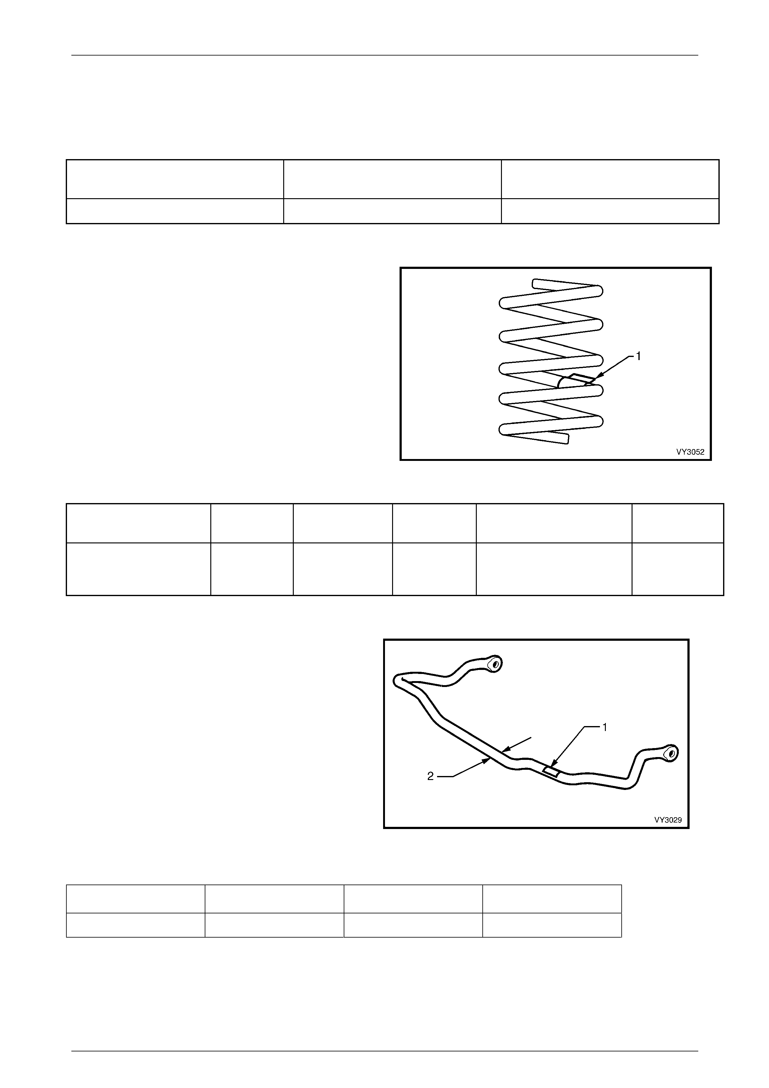
Suspension Page C-64
Page C-64
6 Front Suspension Specifications
Suspension Travel
Suspension Configuration Compression – 2/3 Compressio n of
Bumper (mm) Rebound (mm)
MY 2004 AWD Coupe 4 80 75
Front Spring Details
Identification of the front spring fitted to a particular vehicle
can be achieved by cross-referencing the two digit code
provided on the production identification tag (1) with the
table below.
Figure 3-66
Suspension
Configuration Number of
Coils Free Length
(mm) Part Number Spring Type & Rate Production ID
Code
MY 2004 AWD Coupe 4 6.97 380 03c-043301 VARIABLE
24 – 31 N/mm
(4950 ± 110N @ 184 mm)
Turquoise
coloured tag
Front Stabiliser Bar Details
The stabiliser bar identification is contained in a label (1)
attached to the stabiliser bar.
Front Stabiliser Bar Diameter (2) = 27 mm
Figure 3 – 67
Model Diameter (mm) Part Number Production ID Code
Coupe 4 27 92114524 YC
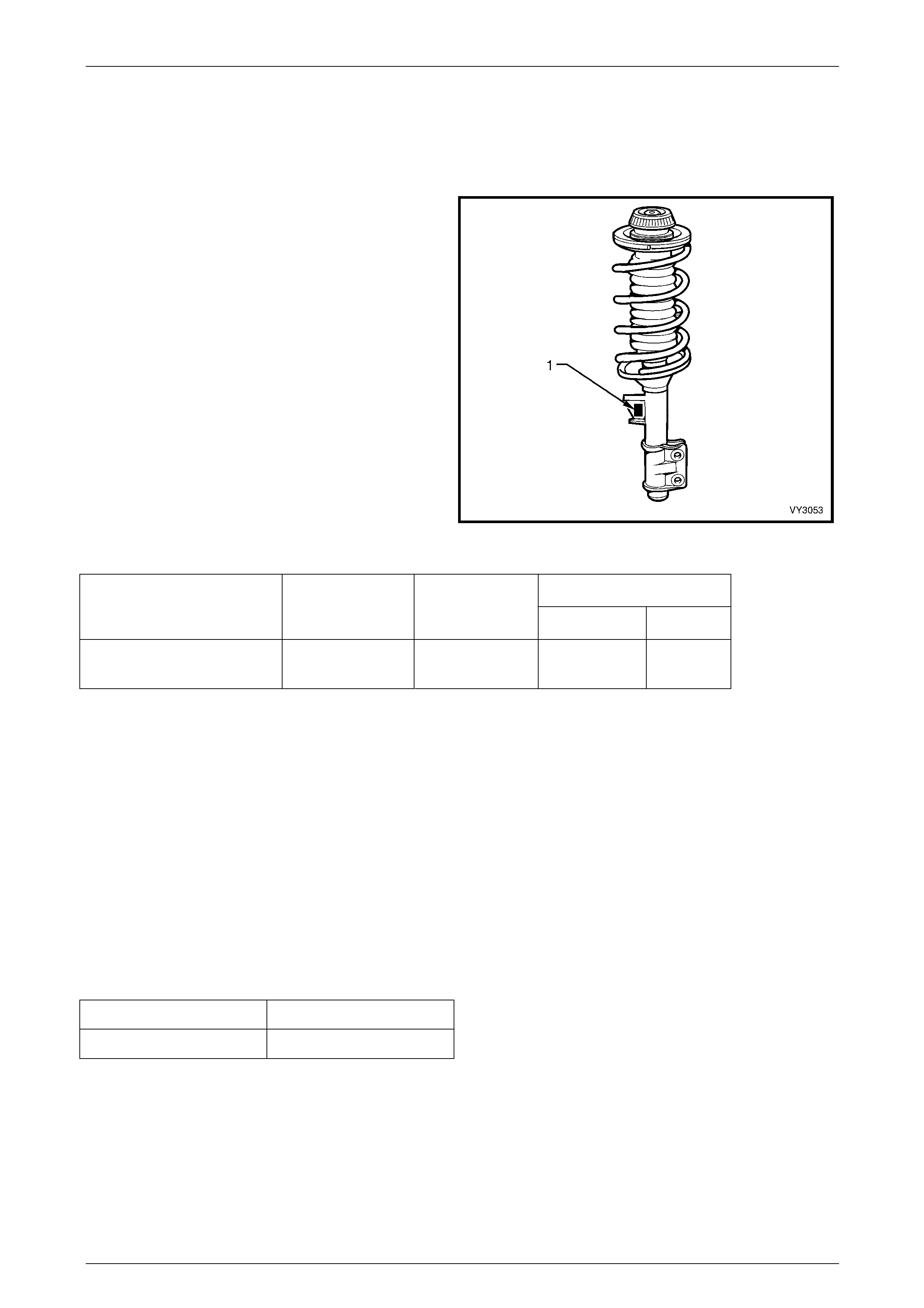
Suspension Page C-65
Page C-65
Front Strut Details
Type Wet strut – non-serviceable
Piston Diameter 30 mm
Identification of the front strut assemblies fitted to a
vehicle, can be achieved by cross-referencing the two
digit code provided on the production identification tag
(1) with the table below.
Figure 3-68
Production ID Code
Suspension Configuration Right Side Strut
Part No. Left Side Strut
Part No. Left Right
Coupe 4 03F-043302 03F-043301 FGL FGR
Front Control Arm Details
Type Cast Aluminuim with a rubber bushing at the rear for attachment to front suspension crossmember cradle. The
hydraulically dampened front bushing is pressed into the front suspension crossmember cradle.
Front Control Arm Ball Joint
The front control arm ball joint assembly is bolted on to the Lower Control Arm and can be serviced separately.
Front Wheel Bearings
Type Double row ball bearing
Lubricant Sealed for life, non-adjustable
Wheel Bearing Angular 'Float'
New Bearing 0.106 mm Maximum
Used Bearing 0.213 mm Maximum
For 'float' measuring procedure, refer to 2.4 Front Wheel Hub Assembly – End Float Checking Procedure, in
Section 3 Front Suspension in the MY2004 AWD Adventra Service Information.
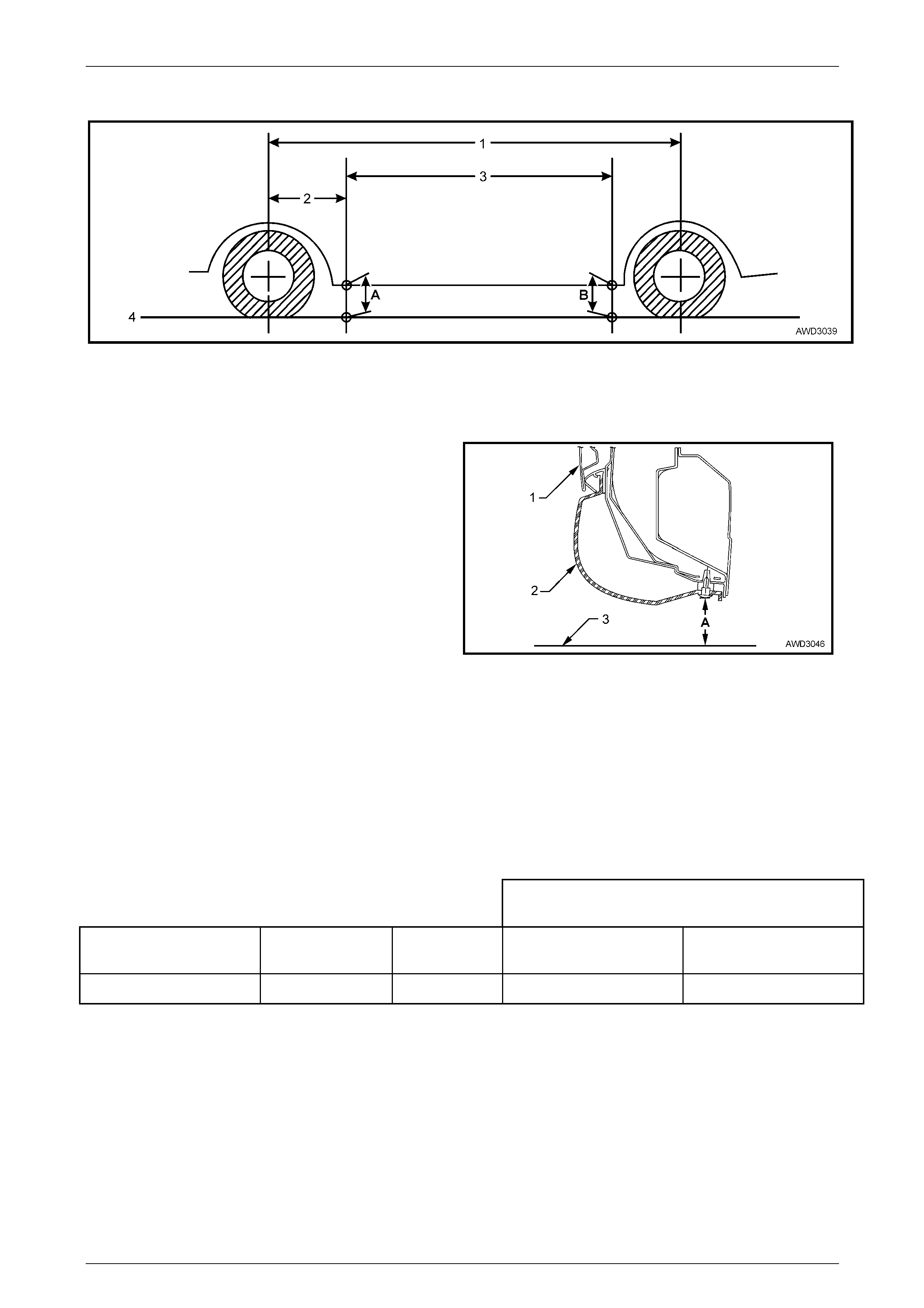
Suspension Page C-66
Page C-66
Suspension Trim Height Specifications
Figure 3-69
A Front Trim Height Check Location
B Rear Trim Height Check Location
1 Wheelbase – 2788 mm
2 Reference Point – 695 mm 3 Trim Height Spacing – 1425 mm
4 Ground Line
The measuring point for the trim height is from the stud to
the ground.
The vehicle must be at curb weight and on level ground.
Legend
A Trim Height
1 Door
2 Trim
3 Ground Line
Figure 3-70– Rear Trim Height Checking Location
(Front Similar)
NOTE
• The following suspension/trim height
dimensions are for reference only and
intended as a guide. Refer to 6 Front
Suspension Specifications for ride height
variations and additional procedures.
• With the plastic wheel aperture fairings fitted
to this vehicle, accurate suspension height
measurements are not possible.
MY 2004 AWD Coupe 4 Model Trim Height
(mm)
VEHICLE DESCRIPTION TRANSMISSION SUSPENSION Front
(‘A’ in Fig. 3-71) Rear
(‘B' in Fig. 3-71)
AWD Coupe 4 Automatic HSV 196 190
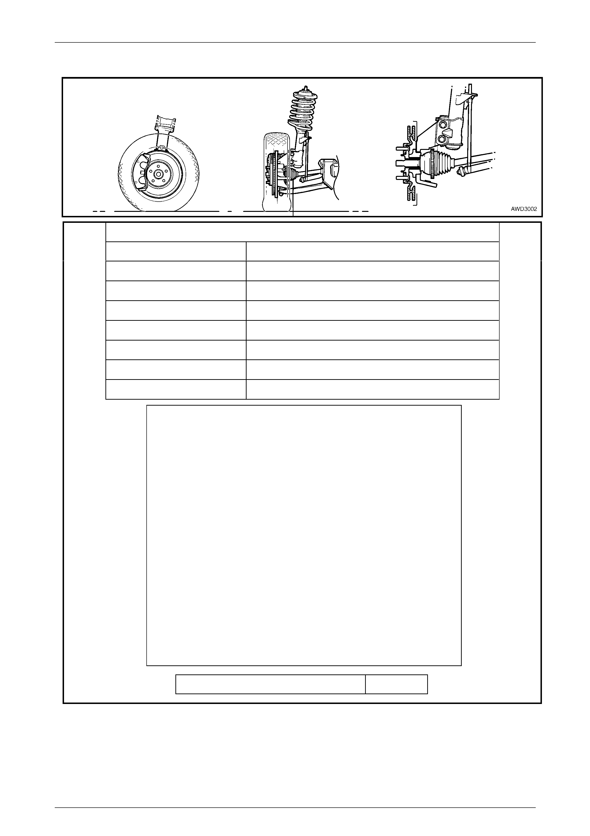
Suspension Page C-67
Page C-67
Front Wheel Alignment Specifications
FRONT WHEEL ALIGNMENT AT CURB WEIGHT
Wheel Alignment Angle Specifications - All Models
Camber -0° 30' ± 0° 10'
Caster 8° 15' ± 1° 15'
Toe-in Degrees Total 0° 10’ ± 0° 10'
Degrees per Wheel 0° 5’ ± 0° 5’
Toe-out on Turns 1° 42’ @ 20 ° turn angle ± 1° 30'
Steering Axis Inclination Angle 16° 36’ ± 1° 30'
Included Angle 16° 06’ ± 1° 30'
SERVICE INFORMATION
• The adjusting values for camber, caster and toe-in must remain within
the tolerances specified. The difference between left and right must not
exceed the following:
CASTER 0° 36'
CAMBER 0° 10'
TOE-IN 0° 10'
• The specifications listed are the nominal value, with acceptable
variance from this central point. Where possible, an attempt should
always be made to achieve the nominal settings when adjusting.
• Front wheel camber alters as a function of front suspension height.
• Camber adjusting bolt: After loosening both lower strut to steering
knuckle bolts and nuts, adjust camber by turning the adjusting bolt
clockwise to decrease negative camber and anti-clockwise to increase
negative camber. After adjustment, both lower strut to steering knuckle
bolts and nuts MUST be replaced with new parts and tightened to the
recommended torque setting.
Fuel Mass with Full Tank - All Models 53 kg
Figure 3-71
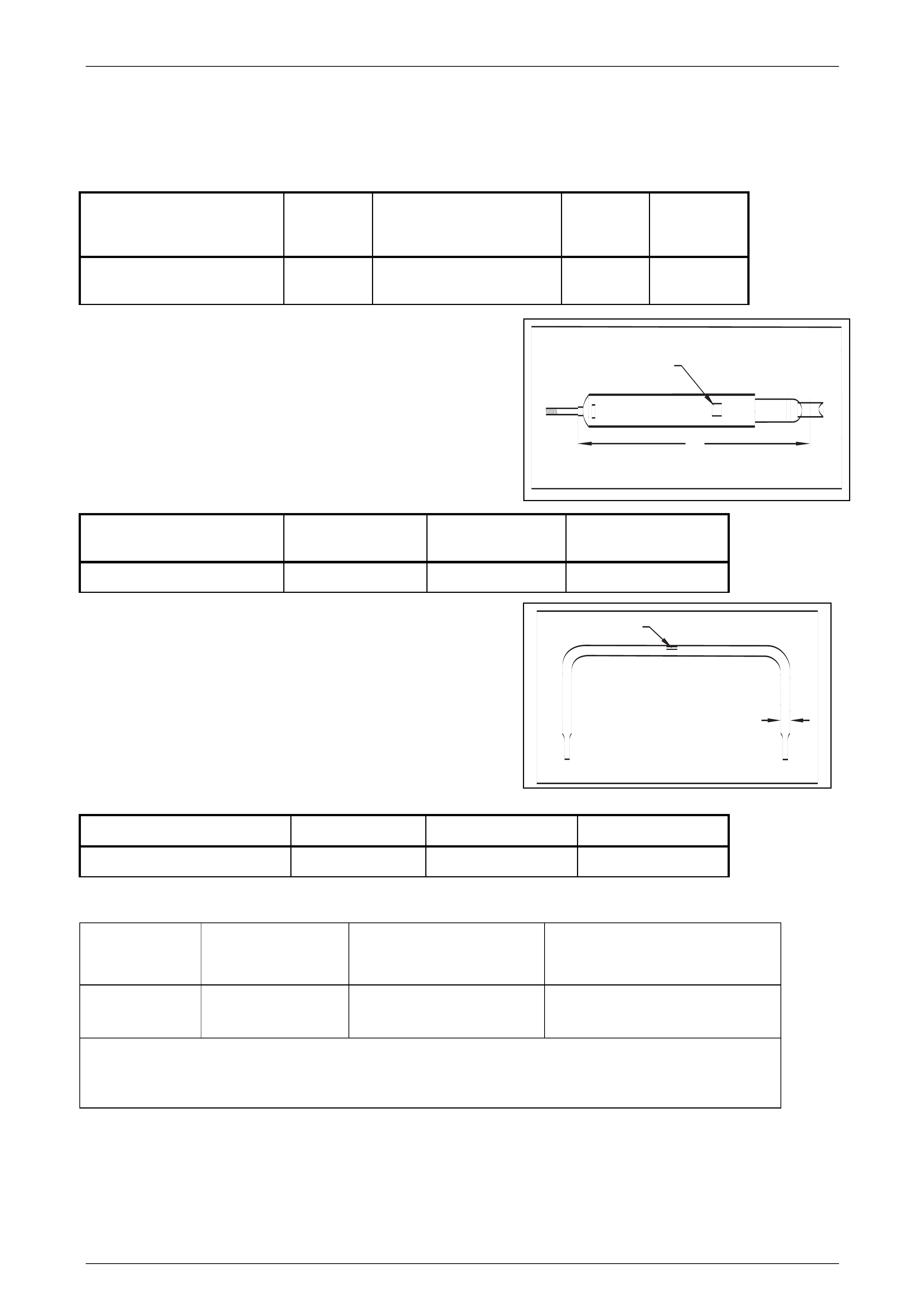
Suspension Page C-68
Page C-68
A
1
1
2
7 Rear Suspension Specifications
Rear Spring Detail
Model Free
Length
(mm)
Spring Type and Rate Part
Number Production
ID Code
AWD Coupe 4 241 Variable 56– 91 N/mm
(55006110 N @ 142.5 mm) 92211562 XB
Rear Shock Absorber Detail
Type: Twin Tube Hydraulic, gas pressurised
Identification of the rear shock absorber fitted to a particular vehicle
can be achieved by cross referencing either the stamped in part
number (see lower damper tube), or production identification code
(1) with the table below.
Model Nominal Extended
Length (A) Part Number Production ID Code
AWD Coupe 4 667 9221563 FG
Rear Stabiliser Bar Detail
Identification of the rear stabiliser shaft fitted to a particular vehicle
can be achieved by cross-referencing the two-digit production
identification tag (1) with the table below.
The table also provides the shaft diameter (2).
Model Diameter (mm) Part Number Production ID Code
Coupe 4 16 92048231 FK
Rear Suspension Service Alignment Data
Suspension
Configuration Rear Track (mm) Rear Wheel Camber
(Variation side to side) Toe Degrees Per Wheel
(Variation side to side)
Coupe 4 1623 -1º50´ to 0º34´ (0º35´
Maximun) 0º5´ to 0º15´ (0º10´ Maximun)
Dimensions shown are for a vehicle at curb height, i.e. vehicle ready to drive with all fluids at the
recommended levels, the fuel tank full and without the driver, passenger/s or luggage.

Suspension Page C-69
Page C-69
8 Torque Specifications
ATTENTION
Fasteners must be replaced after loosening.
Vehicle must be at curb height before final tightening.
Fasten ers either have micro encapsulated sealant applied or incorpo rate a mechanical thread lo ck and
should only be re-used once. If in doubt, replacement is recommended.
Brake Caliper Anchor Plate Retaining Bolt..... Stage 1 .........................85 N.m
Stage 2......... Turn through 30°
Crossmember Cradle To Side Frame Bolt.............................................122 N.m
Front Control Arm Ball Joint Assembly Stud Nut..........................70 N.m ± 35º
Front Control Arm to Ball Joint Assembly Bolts………..........................65 N.m
Front Control Arm Front Isolator Bolt.............................................340 N.m
Front Control Arm Rear Bushing Bolt............................................180 N.m
Front Driveshaft Outer Retaining Nut.......Stage 1:................................130 N.m
Stage 2: Loosen Until Nut is Loose
Stage 3:................................200 N.m
Front Engine Mount Attaching Nut..............................................................80 N.m
Front Wheel Hub Assembly To Steering Knuckle Attaching Bolt..............108 N.m
Front Wheel Speed Sensor Retaining Screw .............................................10 N.m
Hydraulic Pipe to Steering Rack Valve Housing Flare Nut .........................35 N.m
Outer Tie Rod End Stud, Castellated Nut...................................................65 N.m
Road Wheel Attaching Nut.......................................................................125 N.m
Stabiliser Bar Link Ball Stud Nut.................................................................50 N.m
Stabiliser Bar Bushing Bracket Nut.............................................................28 N.m
Steering Knuckle To Strut Attaching Nut Stage 1: ...................85 N.m
Stage 2: .......................100 N.m
Stage 3:......... Turn through 90°
Steering Linkage Tie Rod To Outer Tie Rod End Lock Nut........................65 N.m
Steering Rack Housing To Crossmember Cradle Mounting Bolt
Stage 1: ......................60 N.m
Stage 2: ...... Turn through 50°
Upper Strut Bearing Retaining Nut.............................................................78 N.m
Upper Strut Locating Plate Retaining Nut................................................55 N.m
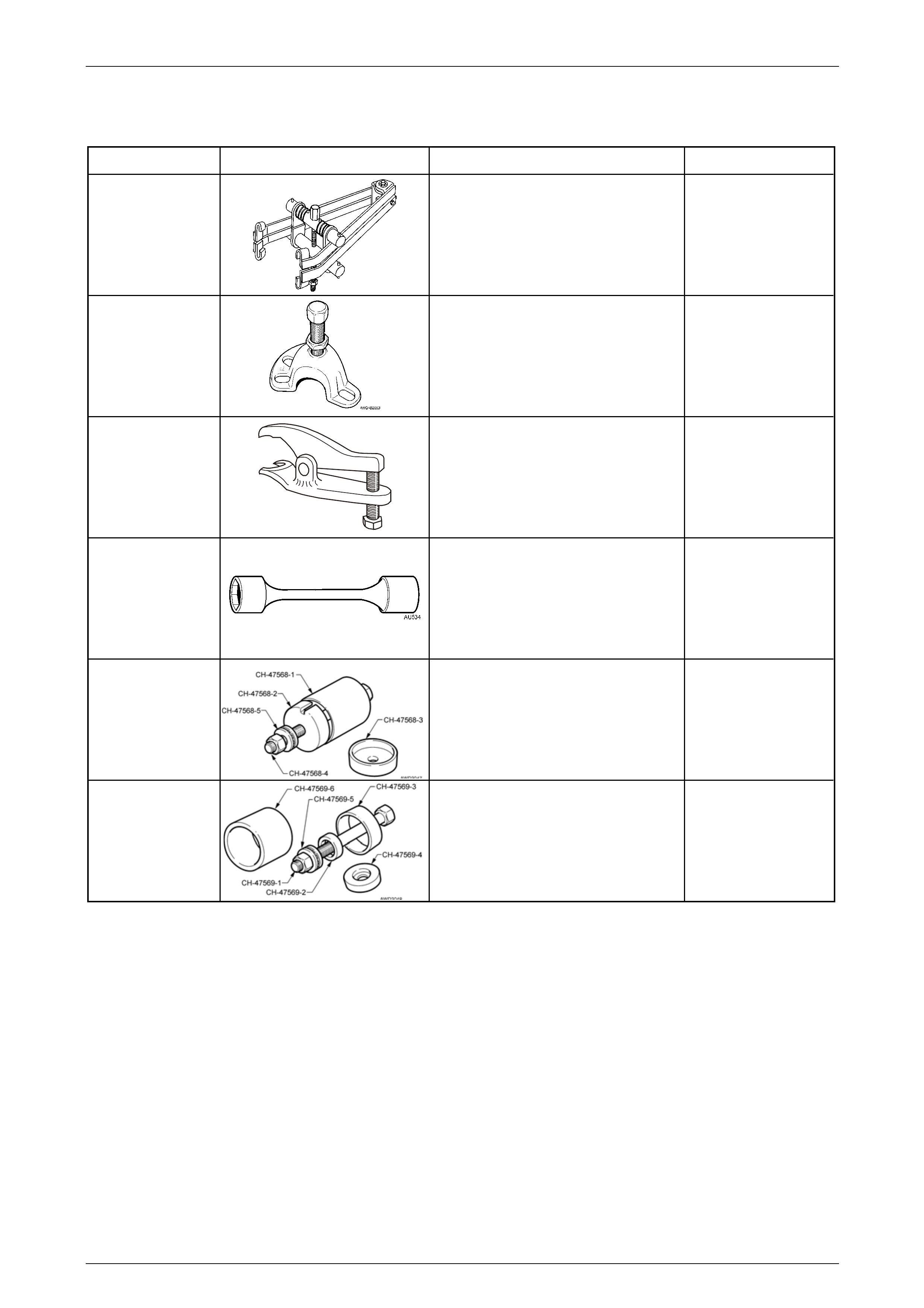
Suspension Page C-70
Page C-70
9 Special Tools
Tool Number Illustration Description Tool Classification
180 Spring Compressor
Used to compress the front
suspension spring, prior to removal.
Previously released
Desirable
7208
Hub Puller
Used to press the front driveshaft from
the front hub. Also used to check LSD
breakaway torque on final drives so
equipped.
Previously released
Mandatory
E9332-A
Socket Assembly Release Tool
Previously released.
Used to release the front lower Control
arm socket from the Steering knuckle
or the rear suspension control arm.
Mandatory
AU-534
Torque Limiting Socket
Used in conjunction with an impact
gun to tighten wheel nuts
Previously released.
Mandatory
CH-47568 Remover/Installer Control Arm,
Front Isolator Bush
Used to remove and install the front
control arm, front hydraulic bushing
from/to the front suspension
crossmember cradle.
New release
Available
CH-47569 Remover/Installer Control Arm,
Rear Bush
Used to remove and install the rear
bushing, from/to the front control arm.
Available
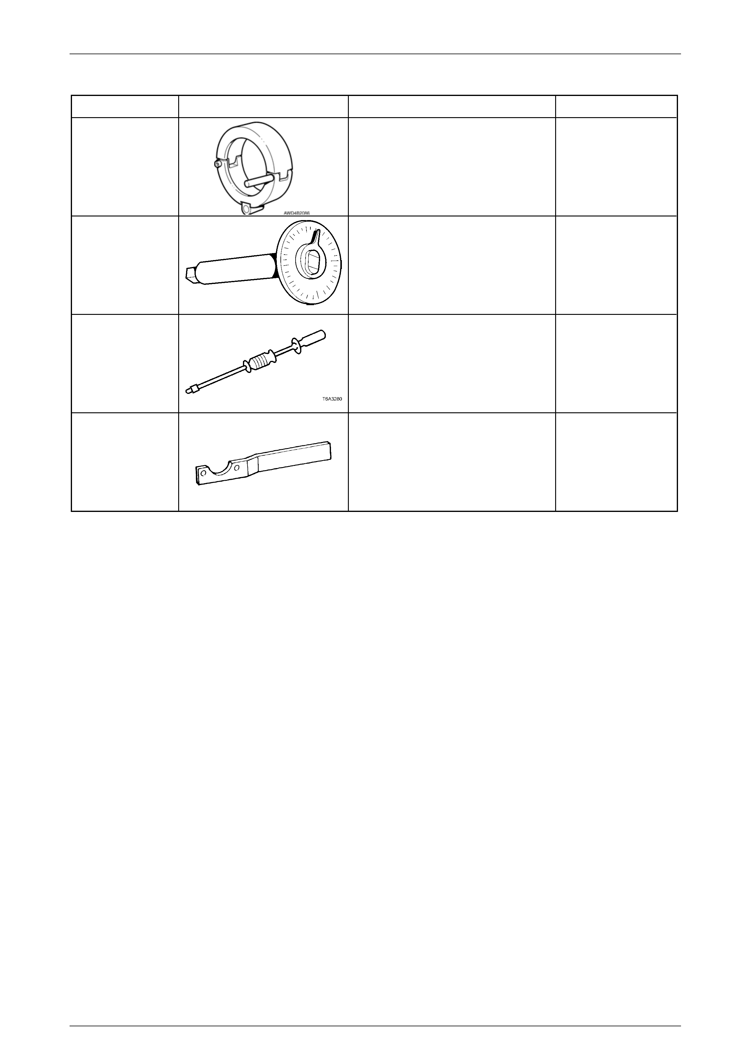
Suspension Page C-71
Page C-71
Tool Number Illustration Description Tool Classification
DT-47570 Remover/Installer, Front
Driveshafts
Used in conjunction with slide hammer
J 6125-1B (and adaptor), or J 23907
slide hammer to remove and reinstall
the front driveshafts.
New release
Mandatory
E7115
Angle Wrench
Used to tighten fasteners that require
and angle torque to be applied.
Previously released.
Mandatory
J 6125-1B
Slide Hammer & Adaptor
Used in conjunction with driveshaft
remover/installer DT-47570.
Previously released.
Available
KM-468
Holding Bar
Used to hold wheel hub assembly
from rotating.
Previously released.
CH-47569