Fuel and Exhaust Systems Page G-1
Page G-1
Section G
Fuel And Exhaust Systems
ATTENTION:
HSV vehicles are equipped with a Supplemental Restraint System (SRS). An SRS consists of seat belt pre-
tensioners (fitted to all front seats), a driver’s-side air bag , a passenger’s-side air bag and right and left hand
side air bags. Refer to CAUTIONS, Section 12M, in Volume 12 of the Holden V2 Series Coupe Service Manual
before performing any service operation on or around SRS components, the steering mechanism or wiring.
Failure to follow the CAUTIONS could result in personal injury or unnecessary SRS system repairs.
1 Purpose...................................................................................................................................................3
1.1 General Information............................................................................................................................................... 3
1.2 Service Operations ................................................................................................................................................ 4
2 Fuel Tank.................................................................................................................................................6
2.1 General Information............................................................................................................................................... 6
Modular Fuel Pump And Sender Assembly......................................................................................................... 9
Fuel Pump .............................................................................................................................................................. 9
Fuel Flow Through The Modular Fuel Pump And Sender Assembly .............................................................. 10
Fuel Limiter Vent Valve........................................................................................................................................ 10
Fuel Tank Pressure Sensor................................................................................................................................. 10
Pressure Regulator.............................................................................................................................................. 10
Fuel Strainer......................................................................................................................................................... 11
Fuel Filter Assembly............................................................................................................................................ 11
Fuel Level Sender Assembly............................................................................................................................... 11
2.2 System Components ........................................................................................................................................... 12
2.3 Fuel Pipe Arrangement........................................................................................................................................ 13
3 Service Operations...............................................................................................................................15
3.1 Quick-Connect Fittings ....................................................................................................................................... 15
3.2 Fuel Tank Siphon Procedure.............................................................................................................................. 16
3.3 Fuel Tank Barrier ................................................................................................................................................. 18
3.4 Fuel Tank Assembly ............................................................................................................................................ 20
Remove................................................................................................................................................................. 20
Reinstall................................................................................................................................................................ 27
3.5 Fuel Filler Neck Assembly................................................................................................................................... 28
3.6 Modular Fuel Pump And Sender Assembly....................................................................................................... 29
Remove................................................................................................................................................................. 29
Test ....................................................................................................................................................................... 31
Disassemble......................................................................................................................................................... 32
Reassemble.......................................................................................................................................................... 35
Reinstall................................................................................................................................................................ 35

Fuel and Exhaust Systems Page G-2
Page G-2
3.7 Fuel Level Sender Assembly............................................................................................................................... 37
3.8 Modular Fuel Pump And Strainer Assembly...................................................................................................... 38
Remove................................................................................................................................................................. 38
Reinstall................................................................................................................................................................ 39
3.9 Fuel Filter Assembly............................................................................................................................................ 40
3.10 Fuel Pressure Regulator ..................................................................................................................................... 41
Remove................................................................................................................................................................. 41
Reinstall................................................................................................................................................................ 41
3.11 Modular Fuel Pump And Sender Assembly O-Rings........................................................................................ 42
3.12 Fuel Tank Pressure Sensor................................................................................................................................. 43
Remove................................................................................................................................................................. 43
Reinstall................................................................................................................................................................ 43
3.13 Fuel Fill Limiter Vent Valve Assembly (FLVV)................................................................................................... 44
Remove................................................................................................................................................................. 44
Reinstall................................................................................................................................................................ 44
3.14 Fuel Filler Cap...................................................................................................................................................... 45
Remove................................................................................................................................................................. 45
Reinstall................................................................................................................................................................ 45
4 Specifications.......................................................................................................................................46
5 Torque Wrench Specifications ...........................................................................................................47
6 Special Tools .................................................................................................................. ......................48
Fuel and Exhaust Systems Page G-3
Page G-3
1 Purpose
The purpose of this supplement is to provide information on the fuel and exhaust systems fitted to the HSV Coupe 4
models. This information is designed to supplement that given in the Holden V2 Coupe Series Service Information, and
details are given where differences occur between the HSV models, and standard Holden models. A series of instruction
drawings detail the design changes and indicate specific part numbers, fitting instructions and relevant notes for vehicle
servicing.
NOTE:
If specific technical data on a HSV model is not
contained in this supplement, obtain data for that
model from the relevant Holden V2 Coupe
Service Manual Supplement. References are
made throughout this section to Holden Service
Manuals, to assist in providing information for
specific service operations.
When hoisting (or jacking) HSV models,
ensure that the liftin g head of the hoist lifts on
the chassis before the arm of the hoist
contacts the side-skirt
1.1 General Information
The fuel system fitted to HSV Coupe 4 models is similar to Holdens US Export GTO models with the exception of the
EVAP Canister Vent System, which is not fitted on non Electronic Throttle Control (ETC) Coupe 4 Models.
All information on non ETC Coupe 4 fuel systems is contained in this section.
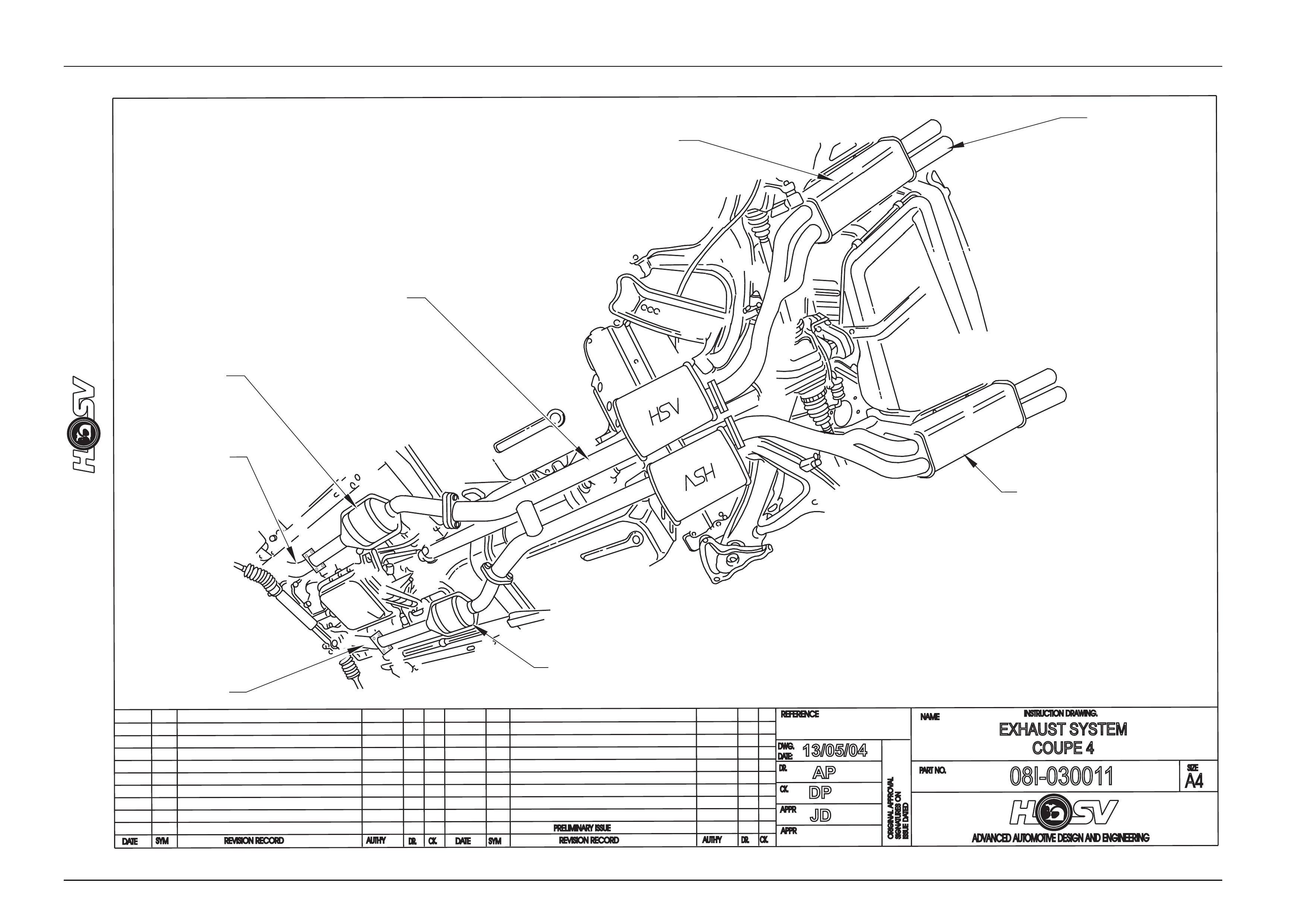
The exhaust system as fitted to the HSV Coupe 4 model is a unique design.
The exhaust system is a “Twin System” including new design headers and intermediate muffler feeding into dual rear
mufflers which have dual outlets with alloy tips.

Fuel and Exhaust Systems Page G-4
Page G-4
1.2 Service Operations
All service operations for the fuel system fitted to HSV Coupe 4 models carry over from Holden V2 Series 3 models.
For information relating to service operations on the fuel tank fitted to HSV Coupe 4 models refer to
Section 8A1 Fuel Tank in the Holden V2 Series 3 models Service Information.
For all service operations for the exhaust system fitted to the HSV Coupe 4 models refer to drawing 08I-030011
Fuel and Exhaust Systems Page G-5
Page G-5
DATE
ISSUEDA
TED
AUTH'Y
CK.
SYM
AUTH'Y
REVISION RECORD
DATE
SYM
SIGNATURES ON
ORIGINAL APPROVAL
DR.
ADVANCED AUTOMOTIVE DESIGN AND ENGINEERING
08I-030011
INSTRUCTION DRAWING.
A4
SIZE
EXHAUST SYSTEM
COUPE 4
REVISION RECORD
PRELIMINARY ISSUE
CK.
NAME
PART NO.
CK.
REFERENCE
DWG.
DR.
DATE:
APPR
APPR
DR.
13/05/04
AP
JD
DP
HEADER LH
08C-032701
CAT CONVERTER-LH
08C-032703
INTERMEDIATE MUFFLER
08C-043301
REAR MUFFLER LH
08C-043303
EXHAUST
EXTENSION
08C-043305
(4 PLACES)
REAR MUFFLER RH
08C-043304
CAT CONVERTER-RH
08C-032704
HEADER RH
08C-032702
Fuel and Exhaust Systems Page G-6
Page G-6
2 Fuel Tank
ATTENTION:
Before performing any Service Operation or other procedure described in this Section, refer to Section 00
CAUTIONS AND NOTES for correct workshop practices with regard to safety and/or property damage.
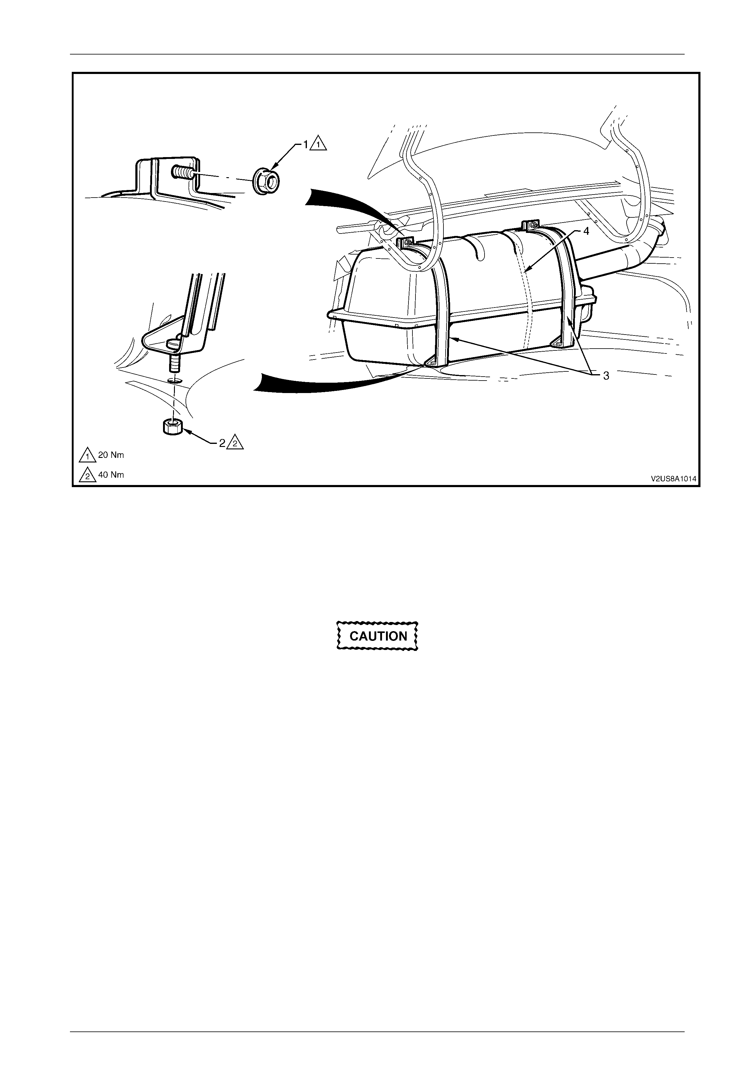
2.1 General Information
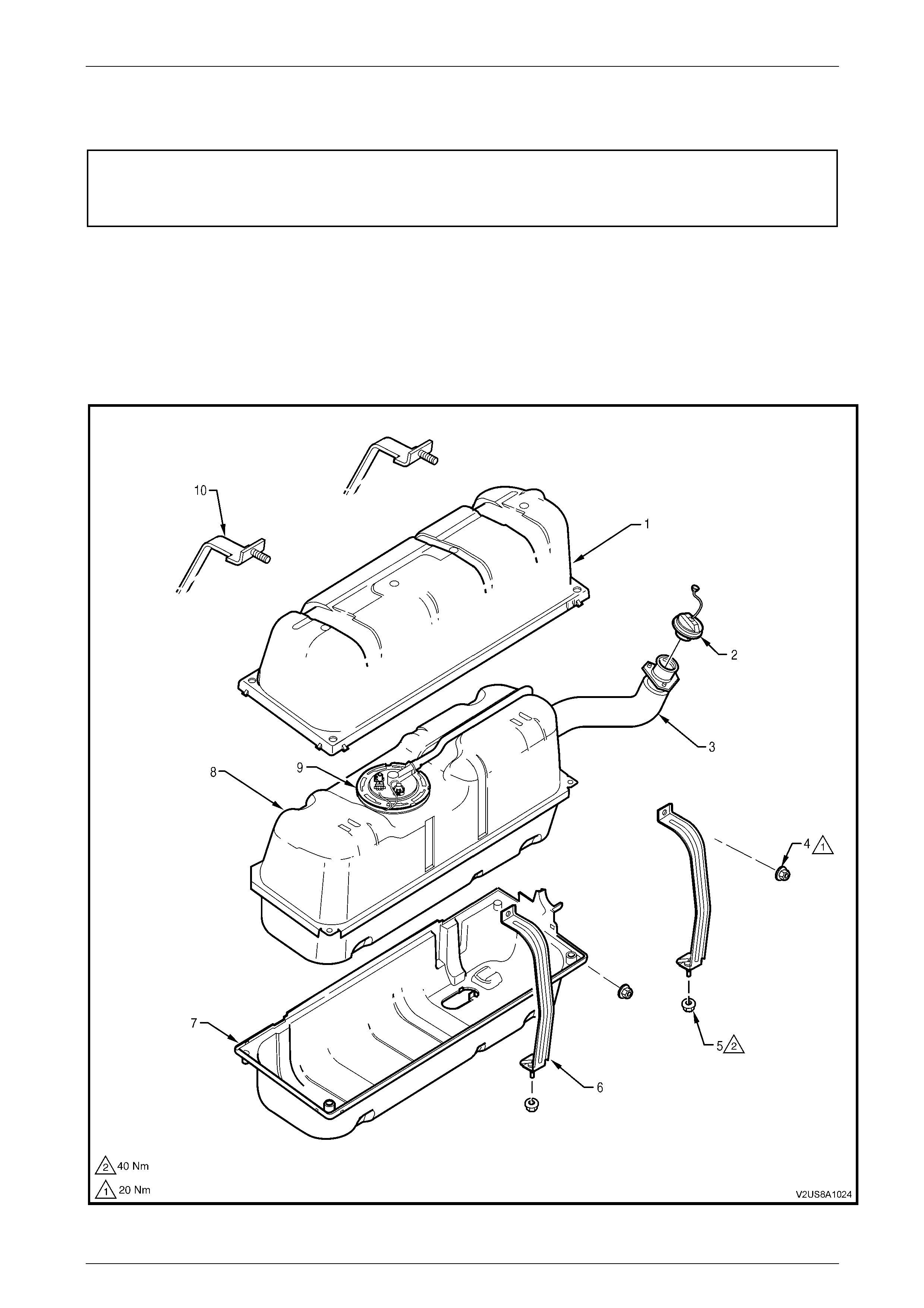
The 70-litre fuel tank fitted to the MY 2004 HSV Coupe 4 is a pressed steel construction. Refer to Figure 8A1 – 1 for the
following. A two piece high density polyethylene shell encapsulates the fuel tank. The fuel tank is fitted immediately
behind the rear seat and is accessed through the rear compartment. The fuel tank is held in place by two mounting straps
and the fuel filler neck is attached to the vehicle body at the fuel filler opening, located in the rear right-hand quarter
panel, with three fastening nuts.
The fuel tank itself is not repairable and if damaged must be replaced.
Figure 8A1 – 1

Fuel and Exhaust Systems Page G-7
Page G-7
Legend
1. Fuel Tank Shell - Upper
2. Fuel Filler Cap
3. Fuel Filler Neck Assembly
4. Mounting Strap Nut - Upper (2 places)
5. Mounting Strap Nut - Lower (2 places)
6. Fuel Tank Mounting Strap (rear facing)
7. Fuel Tank Shell - Lower
8. Fuel Tank
9. Modular Fuel Pump and Sender Assembly
10. Fuel Tank Mounting Strap (front facing)
An in-tank modular fuel pump and sender assembly is attached from the top of the fuel tank and incorporates a modular
fuel pump assembly, a fuel strainer and fuel filter, a reservoir, fuel level sender assembly, pressure regulator and
reservoir jet pump. A fuel fill limiter vent valve (FLVV) and fuel tank pressure sensor is incorporated into the modular fuel
pump and sender cover assembly. The following items of the modular fuel pump and sender assembly are serviceable
items:
• fuel pump and strainer assembly
• fuel filter
• fuel level sender assembly
• fuel pressure regulator
• fuel fill limiter vent valve
• fuel tank pressure sensor
• fuel tank to modular fuel pump and sender assembly seal
• modular fuel pump and sender assembly shaft circlip
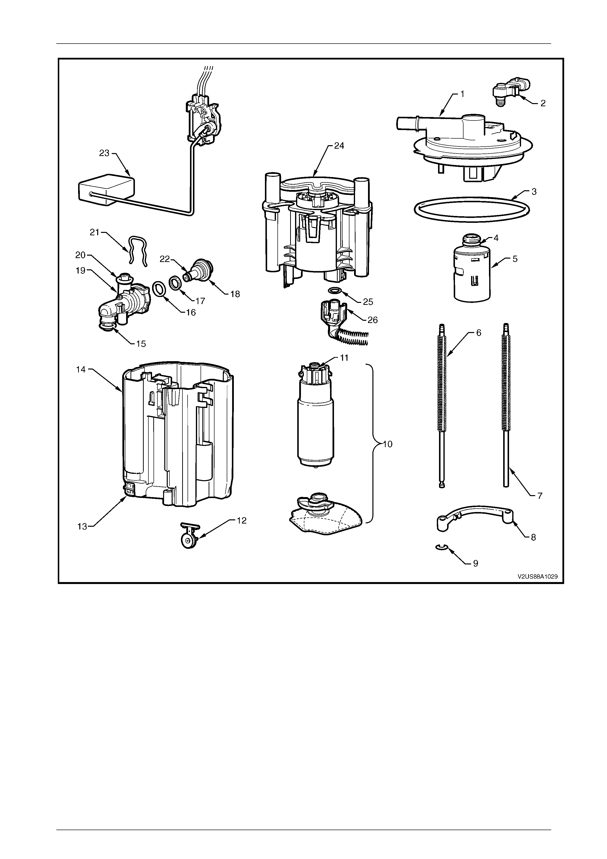
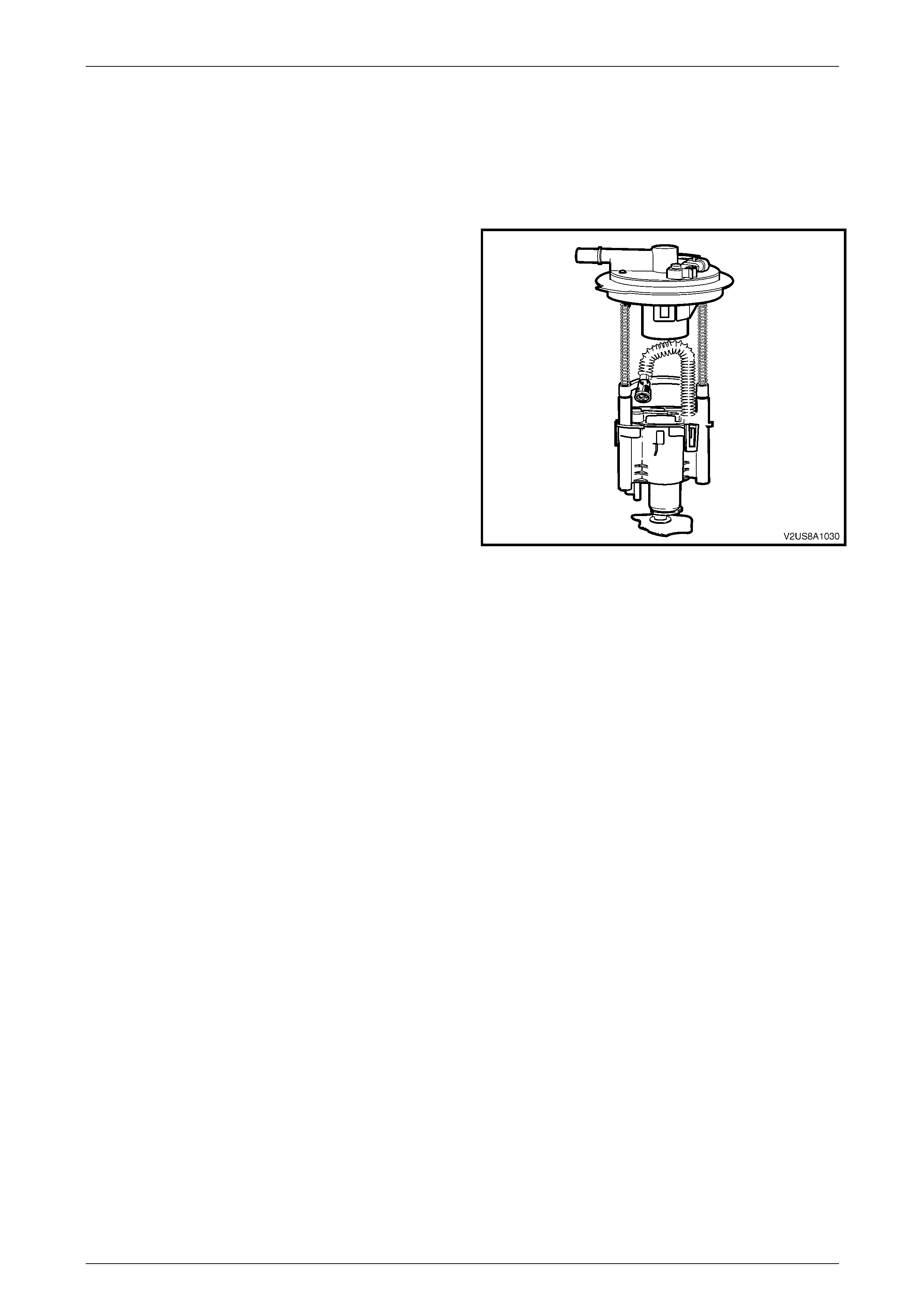
Refer to Figure 8A1 – 2 for an exploded view of the modular fuel pump and sender assembly.
Fuel and Exhaust Systems Page G-8
Page G-8
Figure 8A1 – 2
Legend
1. Modular Fuel Pump and Sender
Assembly Cover
2. Fuel Tank Pressure Sensor
3. Seal
4. O-ring
5. Fuel Fill Limiter Vent Valve (FLVV)
6. Spring (2 places)
7. Shaft (2 places)
8. Wiring Earthing Bridge
9. Circlip
10. Fuel Pump and Strainer Assembly
11. O-ring
12. Flapper Valve
13. Reservoir Jet Pump
14. Reservoir
15. O-ring
16. O-ring
17. Nylon Spacer
18. Fuel Pressure Regulator
19. Regulator Holder
20. O-ring
21. Retaining Clip
22. O-ring
23. Fuel Level Sender Assembly
24. Fuel Filter Assembly
25. O-ring
26. Fuel Outlet Connector
Fuel and Exhaust Systems Page G-9
Page G-9
Modular Fuel Pump And Sender Assembly
The modular fuel pump and sender assembly maintains an optimum fuel level in the reservoir. This ensures a continuous
fuel flow under all fuel level conditions and vehicle attitudes. The modular fuel pump and sender assembly also provides
an accurate means of measuring the fuel level within the fuel tank.
Fuel Pump
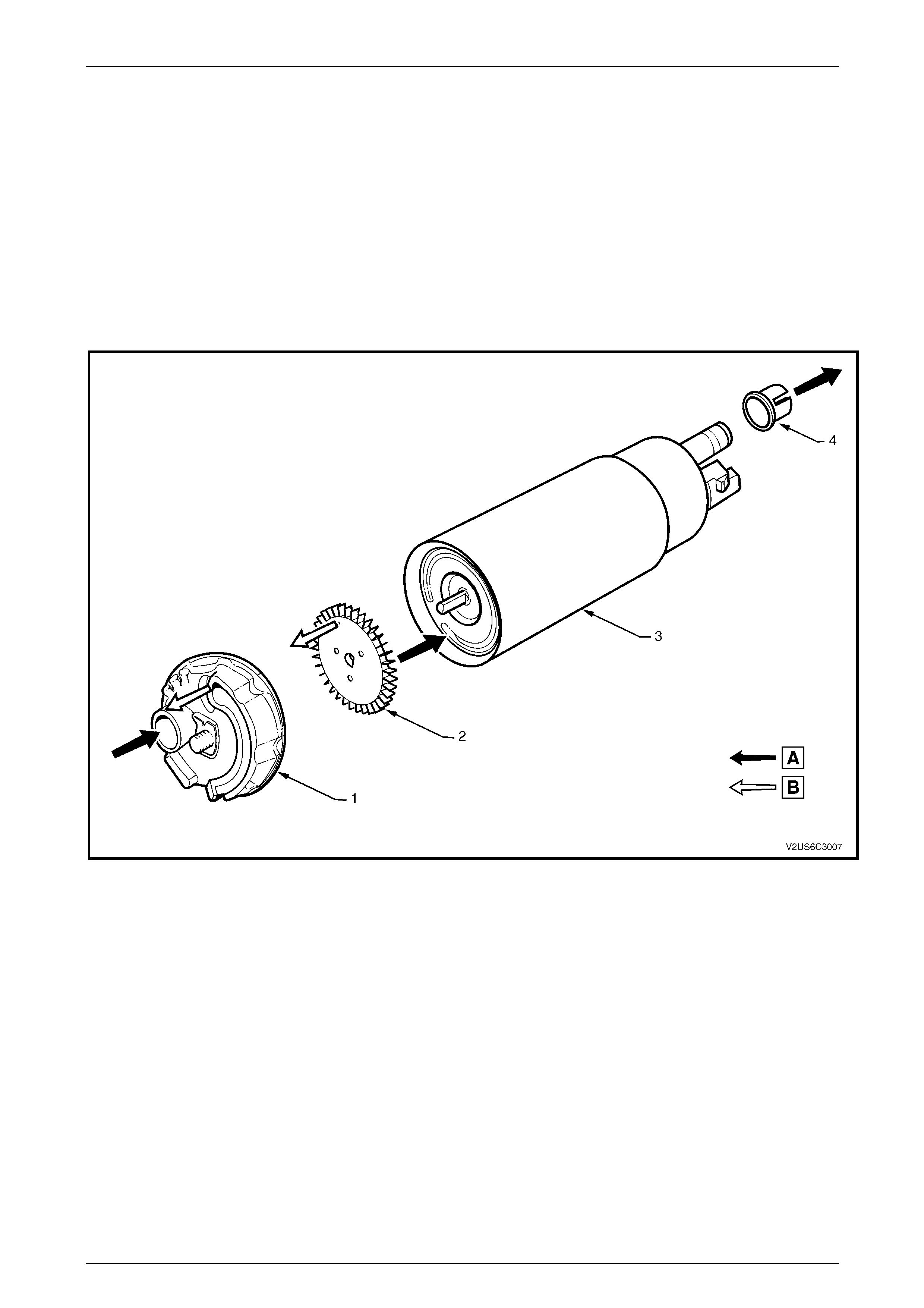
Figure 8A1 – 3 details fuel flow through the fuel pump. The fuel pump is incorporated into the design of the modular fuel
sender assembly inside the fuel tank and is an electric, high pressure, single turbine design. The fuel pump provides fuel
to the fuel rail assembly at a specified flow and pressure.
The fuel pump delivers a constant flow of fuel to the engine, even during low fuel conditions or aggressive vehicle
manoeuvres. The PCM controls the electric fuel pump operation through the fuel pump relay.
Figure 8A1 – 3
Legend
A Fuel
B Vapor Out 1. End Cap
2. Impeller
3. Electric Motor Housing Assembly
4. Pump Outlet O-ring Collar
Fuel and Exhaust Systems Page G-10
Page G-10
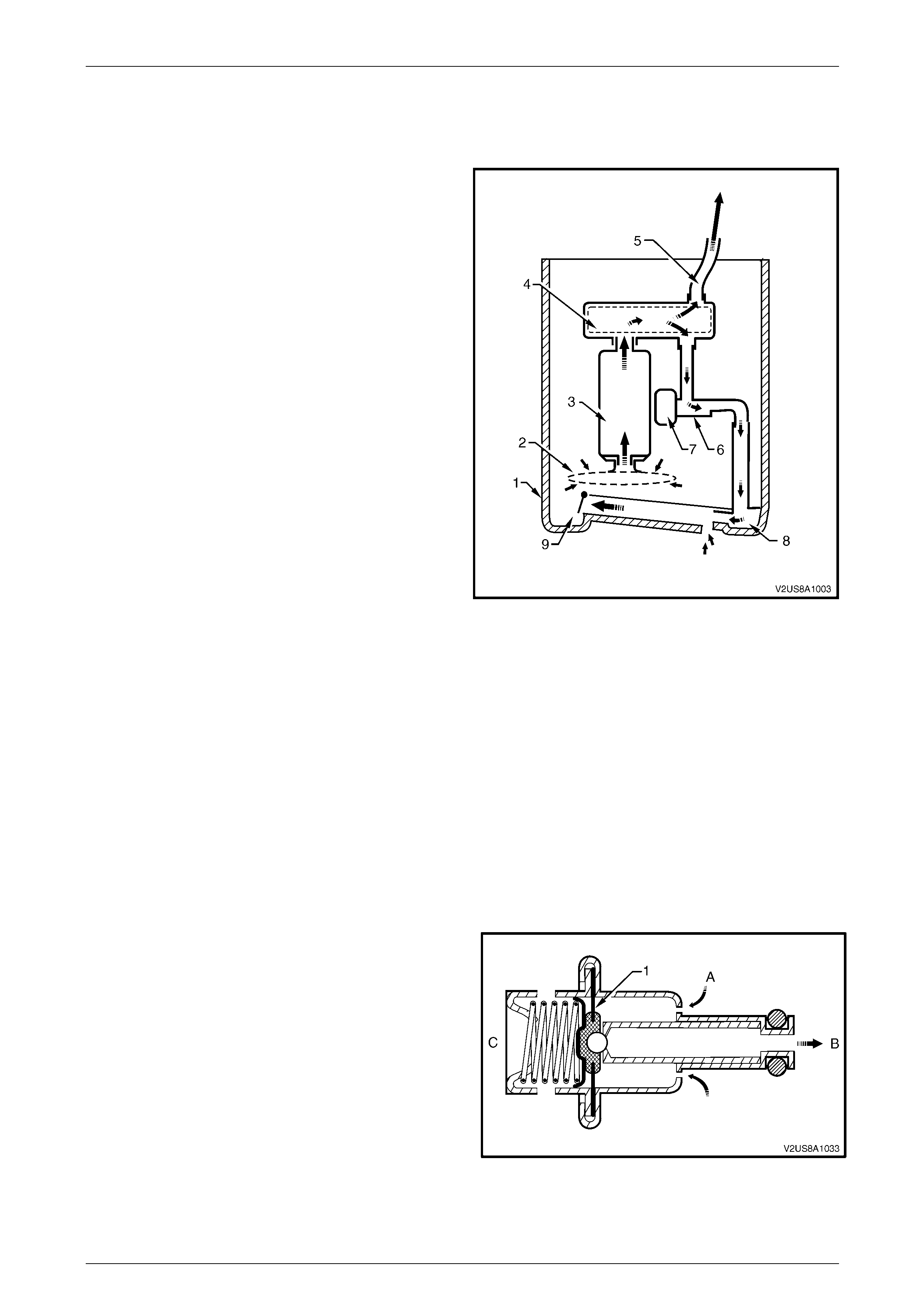
Fuel Flow Through The Modular Fuel Pump And Sender Assembly
This section provides a general description of fuel flow through the modular fuel pump and sender assembly.
Fuel is pumped from the fuel tank to the engine via the
modular fuel pump and sender assembly.
Fuel in the reservoir (1) is drawn through the fuel strainer (2)
and into the single turbine fuel pump (3) which is driven by a
constant-speed motor. Fuel is then forced through the motor
and out, under pressure, into the fuel filter canister and
through the fuel filter (4). There are two fuel filter exit ports,
one runs into a flexible pipe which connects to the engine fuel
feed line (5) within the fuel tank, and the other provides the
connection port to which the fuel pressure regulator holder
and port assembly (6) is connected.
When the engine is operating, fuel is continuously forced to
flow through the ported pressure regulator holder assembly
which has an extended moulding to enable mounting and
provide the fuel exit port. The fuel pressure regulator (7) is
attached to one side of the holder. The exit port directs fuel
into the reservoir jet pump (8), which is moulded integral to
the reservoir assembly. This pump forces extra fuel into the
reservoir through a one way flapper valve (9) connected at
the base of the reservoir.
Figure 8A1 – 4
Fuel Limiter Vent Valve
A fuel limiter vent valve is incorporated into the modular fuel pump and sender cover assembly. This valve controls the
fuel tank fill level by closing the primary vent from the fuel tank and prevents fuel from exiting the fuel tank via the EVAP
vapor pipe to the canister. The valve also provides fuel spillage protection in the event of a vehicle rollover by closing the
vapor path from the fuel tank to the EVAP canister.
Fuel Tank Pressure Sensor
A fuel tank pressure sensor is mounted to the cover of the modular fuel tank and sender assembly. When the Powertrain
Control Module (PCM) commands a vacuum into the fuel system to check for leaks, a potential voltage is induced by the
sensor and this voltage will fluctuate according to the pressure change in the fuel tank. The change in voltage is
monitored by the PCM through a circuit carried through the body wiring harness and fuel tank wiring harness.
Pressure Regulator
The fuel pressure regulator is a diaphragm-operated relief
valve located in the modular fuel pump and sender assembly.
Its principal function is to maintain a controlled pressure at
the injectors at all times by regulating fuel flow into the fuel
feed line.
Fuel flows from the fuel pump, into the fuel filter and is
allowed to exit the filter into the fuel feed line or the fuel
pressure regulator entry port. From here, fuel flows under
pressure into the pressure regulator at location A. When fuel
pressure builds in the fuel feed line, the diaphragm and
valve (1) inside the fuel pressure regulator is progressively
pushed out, allowing fuel to exit through the regulator port at
location B. The valve is otherwise held closed by mechanical
spring pressure applied from side C. Fuel exiting the
regulator is directed into the reservoir jet pump to provide
continuous fuel circulation.
Figure 8A1 – 5
Fuel and Exhaust Systems Page G-11
Page G-11
Fuel Strainer
The fuel strainer connects onto the fuel pump inlet port on the end cap of the fuel pump assembly and consists of a finely
woven plastic filter. A metal compression ring is fitted around the plastic strainer to fuel pump feed port and the complete
fuel strainer assembly is fastened to the fuel pump end cap with a metal speed clip fastener.
The strainers function is to filter fuel contaminants from within the fuel reservoir and also act to wick the fuel. The fuel
strainer is serviced as part of the complete fuel pump and strainer assembly. Fuel stoppage at the strainer indicates an
abnormal amount of sediment in the fuel tank which should be removed before reinstallation of the fuel tank into the
vehicle, refer to 3.4 Fuel Tank Assembly.
Fuel Filter Assembly
The fuel filter assembly is contained within the modular fuel pump and sender assembly reservoir and forms the
containment housing for the fuel pump. The filter comprises a paper element which traps particles in the fuel that may
damage the fuel injection system. The fuel filter is made to withstand maximum fuel system pressure, changes in
temperature and exposure to fuel additives.
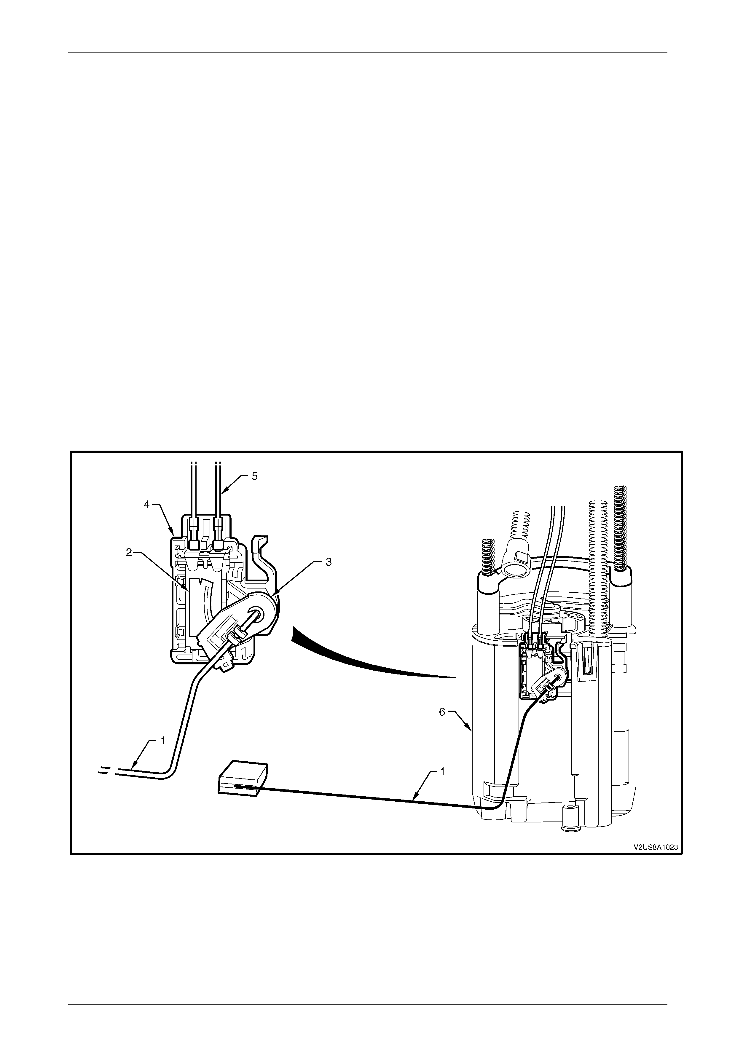
Fuel Level Sender Assembly
Refer to Figure 8A1 – 6 for details of the fuel level sender assembly. The fuel level sender assembly comprises of a fuel
level float and wire arm assembly (1), a ceramic variable resistor card assembly (2), and a detachable nylon wiper (3).
The ceramic resistor card is attached to a plastic card holder (4) which attaches to the reservoir (6). A metal contact fork
with brushes is connected to the detachable nylon wiper. This assembly provides a variable circuit resistance to the
Powertrain Control Module (PCM) depending on wiper contact position. Two circuit wires (5) run from the resistor card
and extend up to connect with the modular fuel pump to cover assembly wiring connector on the underside of the
modular fuel pump and sender assembly cover. The Powertrain Control Module (PCM) averages out any slosh variation
in the fuel tank and sends this signal to the fuel level indicator on the instrument panel fuel gauge.
Figure 8A1 – 6
Legend
1. Fuel Level Float and Wire Arm Assembly
2. Ceramic Variable Resistor Card
3. Nylon Wiper
4. Card Holder
5. Circuit Wires
6. Reservoir
Fuel and Exhaust Systems Page G-12
Page G-12
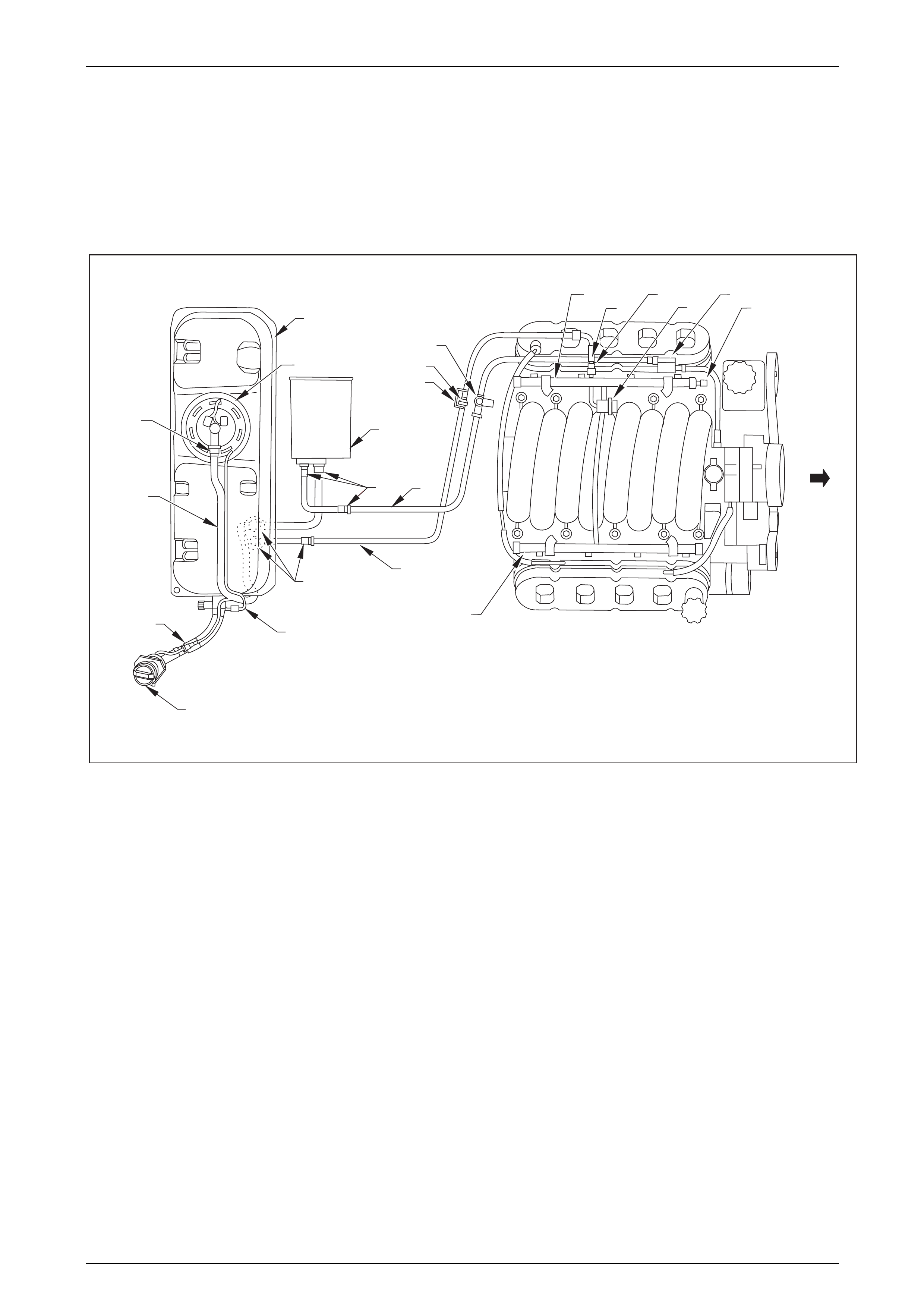
2.2 System Components
Refer to Figure 8A1 – 7 for general components of the fuel control systems. A 2.1L three port vapor canister is mounted
with a bracket onto the underneath the vehicle. The canister cannot be repaired and is serviced only as a complete
assembly. The canister is designed to store vapor from the fuel tank via the tank vent line and release it to the engine via
the canister purge line. A purge line service port is attached along the purge line within the engine bay. Various styles of
quick-connect fittings are used at most fuel line connections, including the modular fuel pump and sender assembly, fuel
vapor canister, fuel filter and fuel feed line, at both the fuel tank and engine ends.
1
2
3
4
5
6
7
89
10 11
12
13
14
15
1617
18
19
20
21
22
Figure 8A1 – 7
Legend
1. Fuel tank
2. Modular Fuel Pump and Sender Assembly
3. Body Wiring Harness to Fuel Tank Wiring Harness Connector
4. Fuel Tank Fill Cap
5. Fuel Fill Neck Vapor Recirculation Line and Quick Connect Fitting
6. Fuel Tank to EVAP Canister Vapor Vent Hose
7. Quick Connect Fitting
8. Quick Connect Fittings
9. Fuel Feed Line to Fuel Rail
10. Quick Connect Fittings
11. Vapor Purge Pipe to Purge Solenoid
12. EVAP Canister
13. Secondary Clip
14. Quick Connect Fitting
15. Service Port and Quick Connect Assembly
16. Fuel Rail, Bank 1
17. Secondary Clip
18. Quick Connect Fitting
19. Fuel Pulse Dampener
20. EVAP Canister Purge Solenoid
21. Fuel Pressure Check Schrader Valve
22. Fuel Rail, Bank 2
Fuel and Exhaust Systems Page G-13
Page G-13
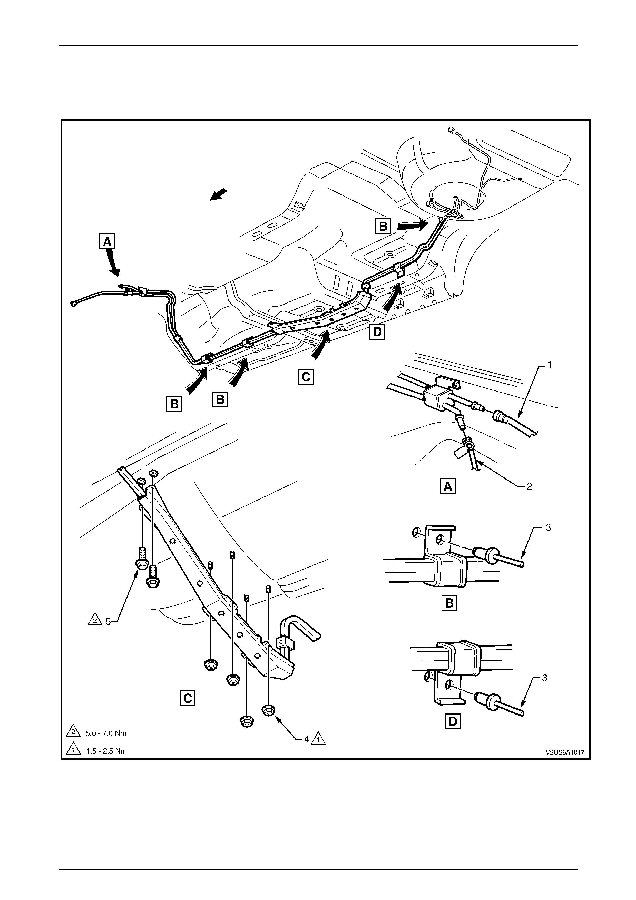
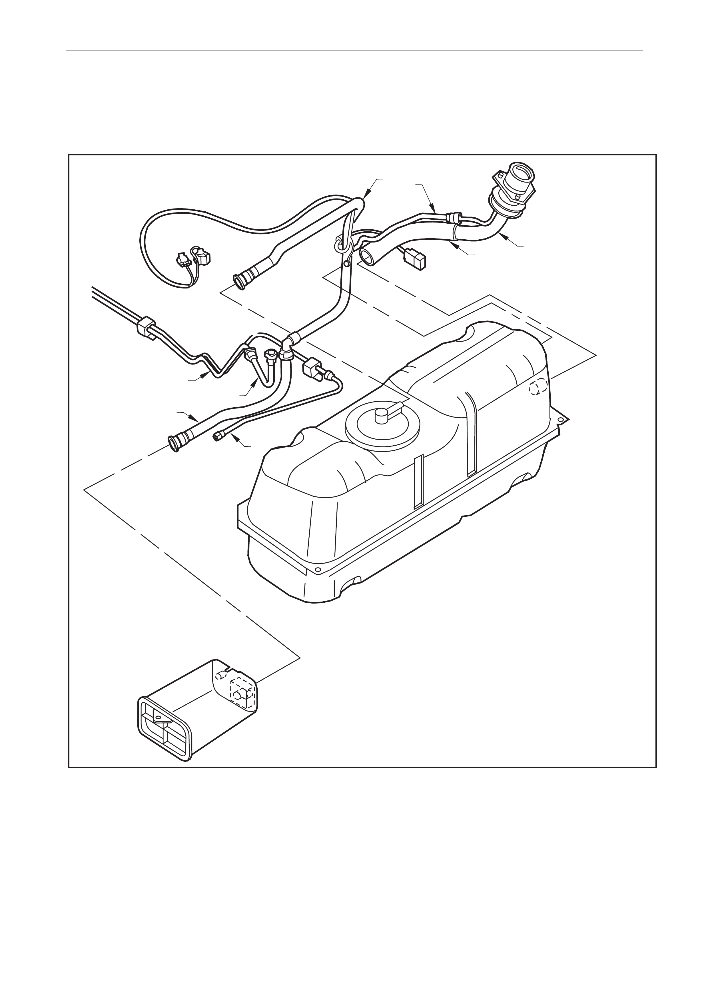
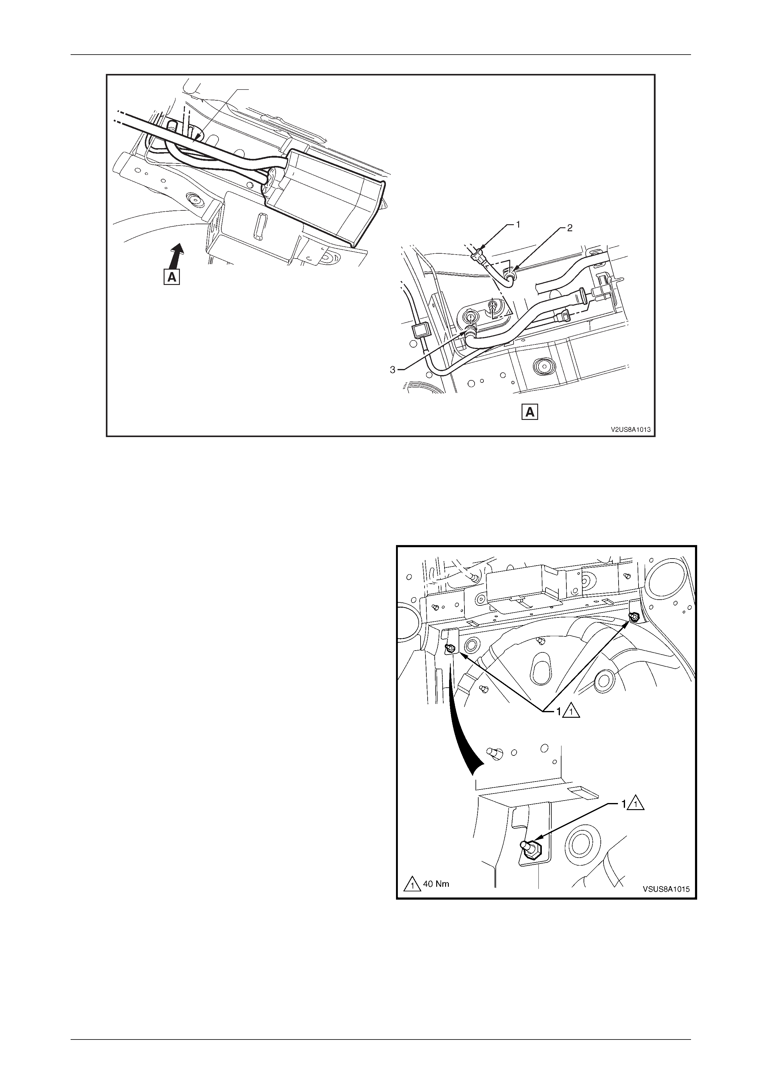
2.3 Fuel Pipe Arrangement
Figure 8A1 – 8 and Figure 8A1 – 9 illustrate the fuel pipe layout and location of other fuel tank related items.
Figure 8A1 – 8
Legend
1. Fuel Feed to Engine Line
2. EVAP Purge to Engine Line 3. Fuel Line Bracket Pop Rivet
4. Stone Guard Securing Nut (4 places) 5. Stone Guard Securing Bolt (2 places)
Fuel and Exhaust Systems Page G-14
Page G-14
NOTE
Refer to Figure 8A1 – 8, if necessary, use special
tool 7371 to remove the fuel feed to engine line
quick-connect fitting (1), refer to
3.1 Quick-Connect Fittings in this Section.
12
3
4
5
6
7
8
Figure 8A1 – 9
Legend
1. EVAP Vapor Line (upstream)
2. EVAP Vapor Recirculation Line
3. Fuel Filler Neck
4. Fuel Filler Hose
5. Fuel Feed Line
6. Fuel Feed Line Extension Elbow
7. EVAP Vapor Line (downstream)

Fuel and Exhaust Systems Page G-15
Page G-15
3 Service Operations
3.1 Quick-Connect Fittings
For information on correct servicing procedures of quick-connect fittings, refer to Section 6C3-3 Service Operations
(GEN III V8 Engine), 3.15 Fuel Hose/Pipes (Rear Pipes) in the MY2003 VY & V2 II Series Service Information.
Fuel and Exhaust Systems Page G-16
Page G-16
3.2 Fuel Tank Siphon Procedure
The fuel system will contain fuel in the
modular fuel pump and sender assembly and
fuel lines that can be spilled during service
operations. Ensure no naked flames or other
ignition sources are nearby. Ensure all mobile
phones (and transmission devices that may
cause any metal objects to become
unintentional receiving antennas) are
switched off.
Place a dry chemical (Class B) fire
extinguisher nearby before performing any
on-vehicle service procedures. Failure to
follow these precautions may result in
personal injury.
For a general exploded view of fuel tank components, refer to Figure 8A1 – 1.
1. Relieve the fuel system pressure. Refer to Section 6C3-3 Service Operations (GEN III V8 Engine),
3.7 Fuel Pressure Relief Procedure in the MY2003 VY & V2 II Series Service Information.
2. Reinstall the fuel pump relay R16, refer to Refer to Section 6C3-3 Service Operations (GEN III V8 Engine),
3.6 Fuel Pump Relay in the MY2003 VY & V2 II Series Service Information.
3. Disconnect the negative battery terminal.
NOTE
Disconnection of the battery affects certain
vehicle electronic systems. Refer to Section 00,
Cautions, 5 Battery Disconnection Procedures, in
the MY2004 VY & V2 Series Service Information
before disconnecting the battery.
4. Remove the fuel filler cap.
Fuel and Exhaust Systems Page G-17
Page G-17
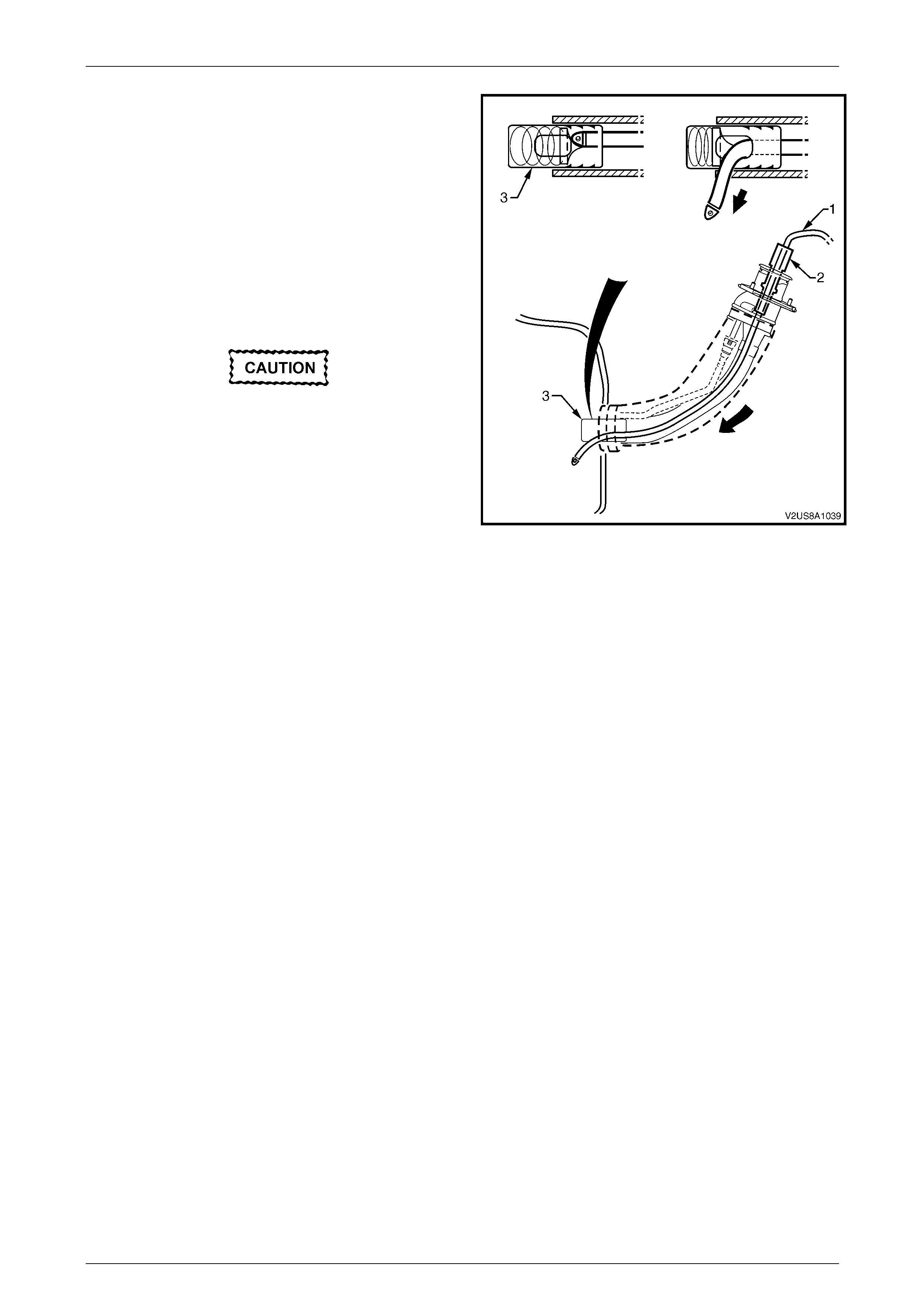
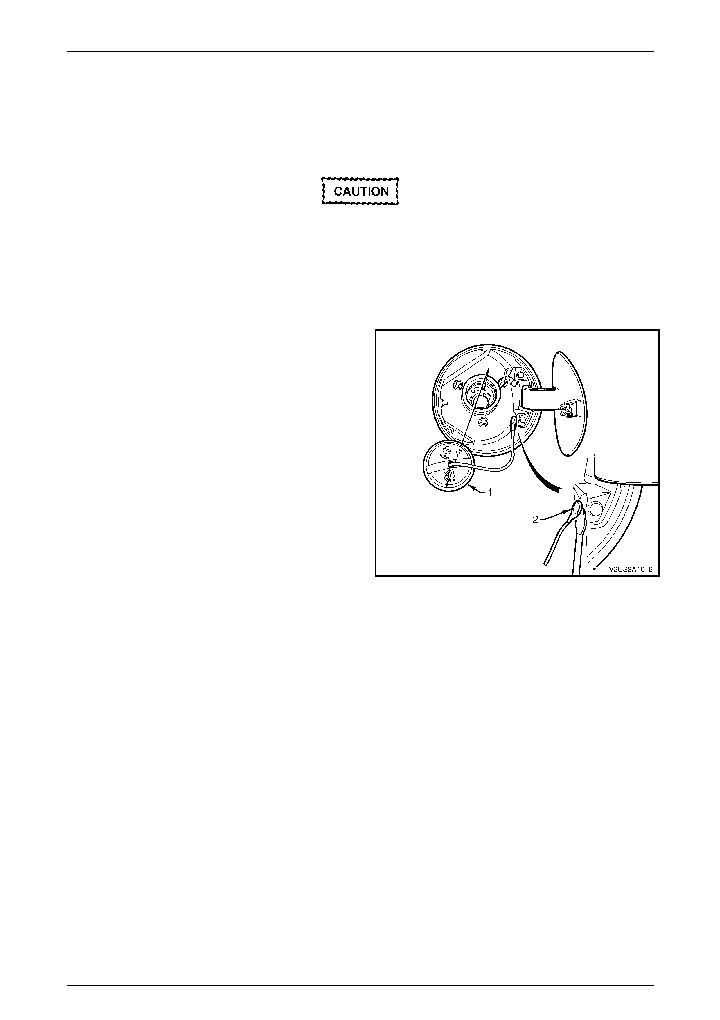
5. Install J44284–2 flapper door holder (2) into the fuel filler
neck in order to hold the door open.
NOTE
Lubricate the fuel siphon hose with J36850
Transjel Transmission Assembly Lubricant or
equivalent to aid hose insertion. Do not use an
unapproved lubricant.
6. Insert the J45004-1 fuel tank siphon hose (1) into the fuel
tank filler neck and gradually twist it around until the tip of
the hose meets the fuel tank check valve (3) and
continues to the bottom of the fuel tank.
7. Use a hand or air operated pump device in order to
siphon as much fuel through the fuel fill pipe as possible.
Never siphon or store fuel into an open
container. Always use and approved fuel
storage container in order to reduce the
chance of fire, explosion or con t amin atio n.
Figure 8A1 – 10
NOTE
Never use excessive force when removing the
siphon hose from the fuel filler neck. If the fuel
siphon hose gets stuck upon removal, gently twist
and tug the hose back and forth until it releases.
NOTE
If fuel does not siphon from the fuel tank, the fuel
hose may have entered the fuel tank through a
roof facing opening of the check valve. If
necessary, repeat step 6 above but twist the hose
by 90 degrees as it is sliding down the filler neck.
This will enable the siphon hose to enter into the
fuel tank through a floor facing check valve
opening.
NOTE
The siphon procedure will not remove all fuel
from the fuel tank. If necessary, fuel remaining in
the fuel tank may be siphoned out through the top
of the fuel tank, once the modular fuel pump and
sender assembly is removed from the tank, refer
to 3.6 Modular Fuel Pump And Sender
Assembly.

Fuel and Exhaust Systems Page G-19
Page G-19
DATE
ISSUE DATED
AUTH'Y
CK.
SYM
AUTH'Y
REVISION RECORD
DATE
SYM
SIGNATURES ON
ORIGINAL APPROVAL
DR.
ADVANCED AUTOMOTIVE DESIGN AND ENGINEERING
08I-030014
INSTRUCTION DRAWING.
A4
SIZE
FUEL TANK BARRIER
COUPE 4
REVISION RECORD
PRELIMINARY ISSUE
CK.
NAME
PART NO.
CK.
REFERENCE
DWG.
DR.
DATE:
APPR
APPR
DR.
02/07/04
AP
DP
JS
Fuel and Exhaust Systems Page G-20
Page G-20
3.4 Fuel Tank Assembly
Remove
The fuel system will contain fuel in the
modular fuel pump and sender assembly and
fuel lines that can be spilled during service
operations. Ensure no naked flames or other
ignition sources are nearby. Ensure all mobile
phones (and transmission devices that may
cause any metal objects to become
unintentional receiving antennas) are
switched off.
Place a dry chemical (Class B) fire
extinguisher nearby before performing any
on-vehicle service procedures. Failure to
follow these precautions may result in
personal injury.
For a general exploded view of fuel tank components, refer to Figure 8A1 – 1.
1. Siphon as much fuel as possible from the fuel tank, refer to 3.2 Fuel Tank Siphon Procedure.
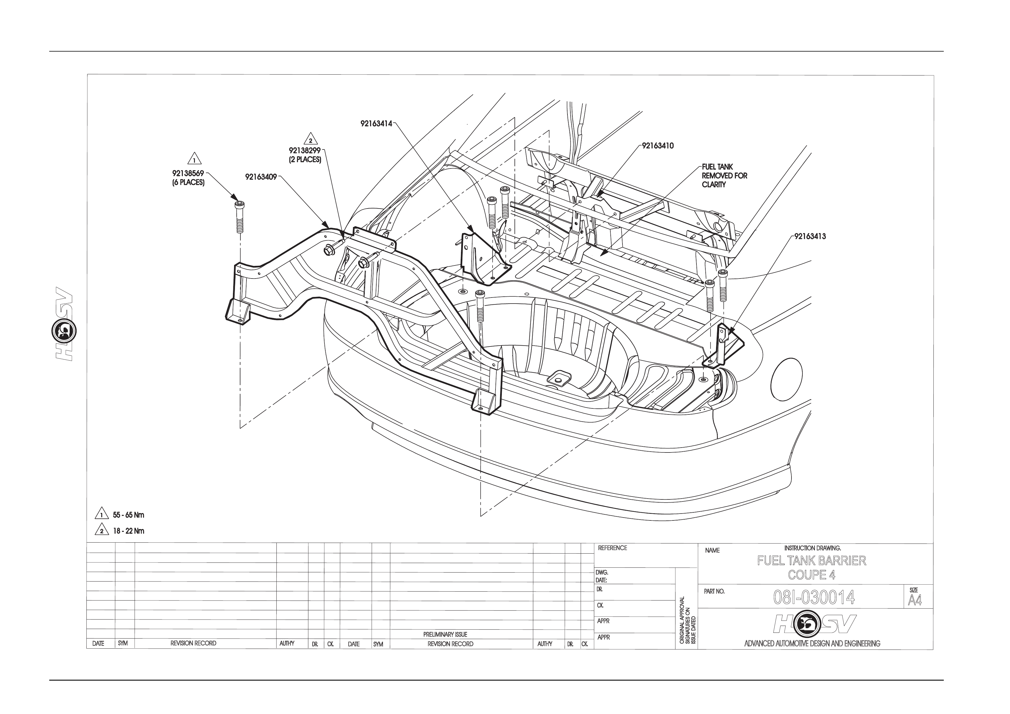
2. Remove the fuel tank brace to gain access to the fuel tank, refer to Drawing 08I-030014 Fuel Tank Brace.
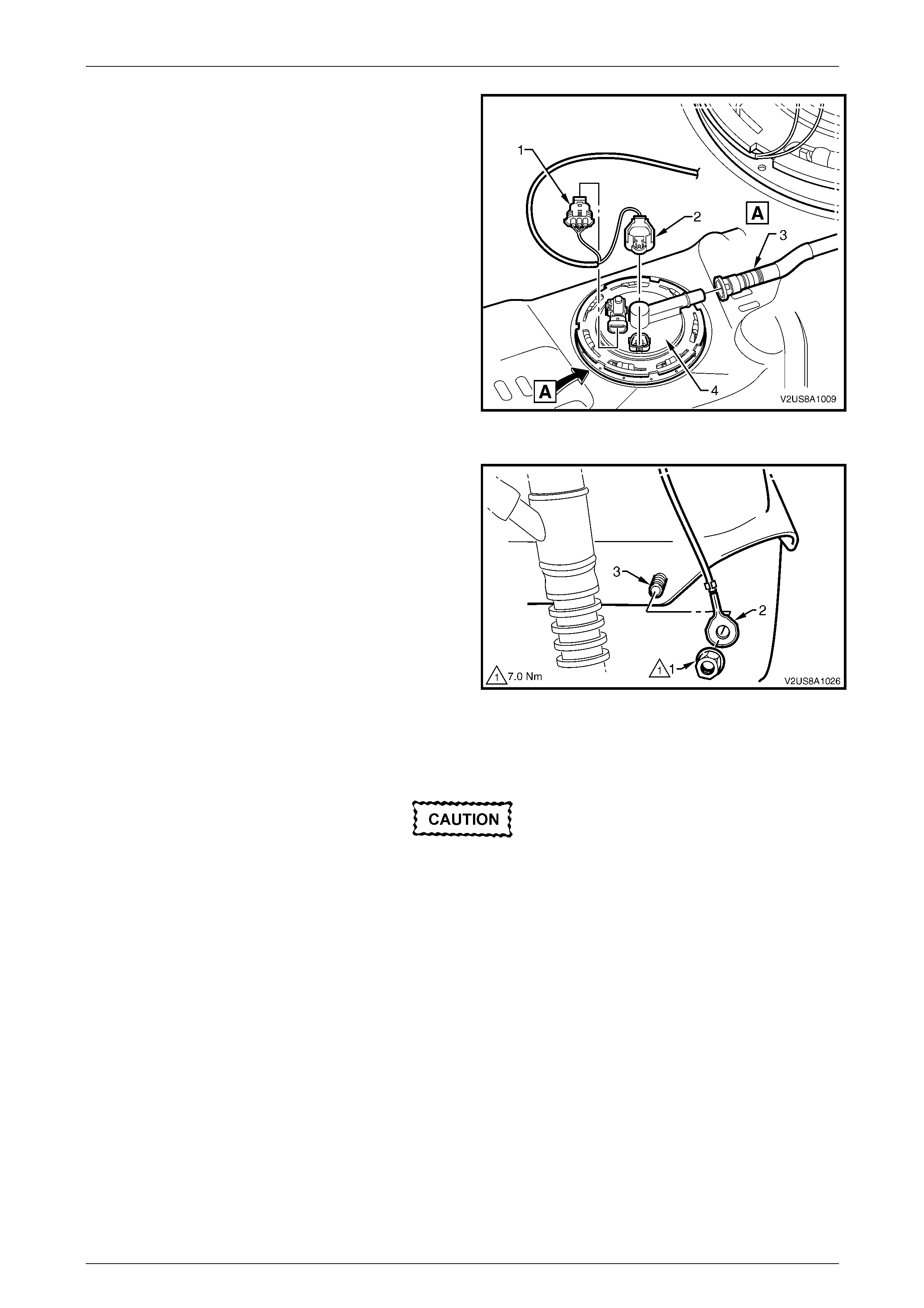
3. Disconnect the body wiring harness to fuel tank harness
connector (1) by depressing the release tang on the
inboard facing face of the connector and pulling the
connector out from the fuel tank harness connector (2).
Figure 8A1 – 11
Fuel and Exhaust Systems Page G-21
Page G-21
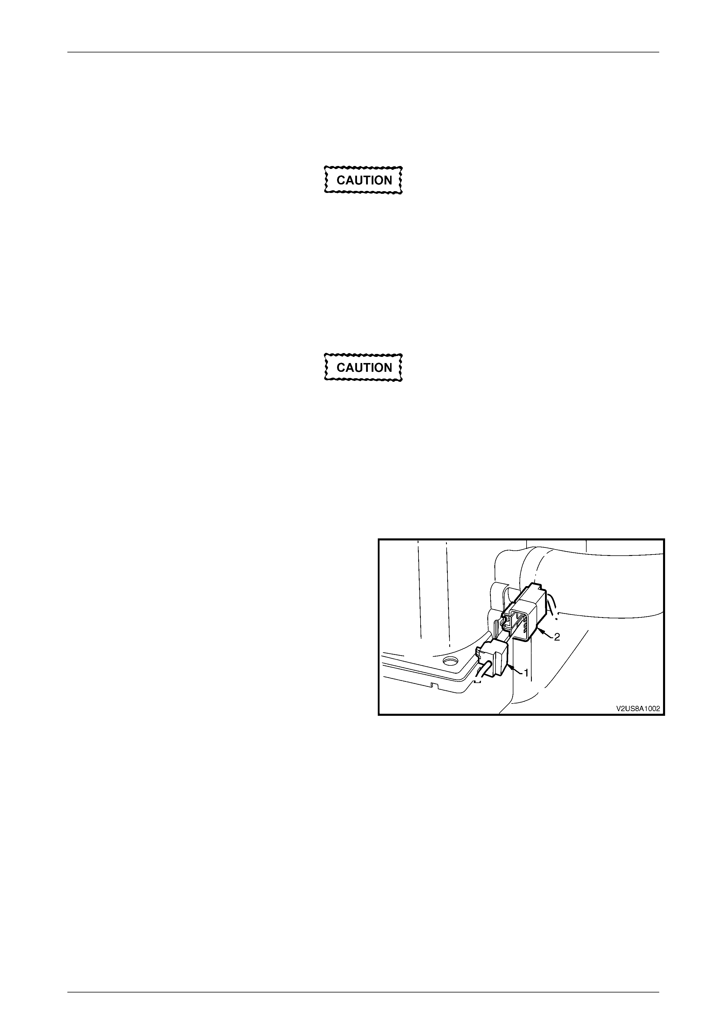
4. From behind the fuel filler door (1), unscrew the fuel filler
cap (4) and cover the end of the fuel filler neck with a
suitable material to prevent foreign objects from entering.
5. Remove the three nuts (2) securing the fuel filler neck to
the filler pocket (3).
Figure 8A1 – 12
6. Refer to Figure 8A1 – 13 for the following:
From underneath the vehicle:
a. Disconnect the fuel feed line quick connect fitting (1)
b. Disconnect the fuel tank to fuel feed line quick connect fitting (2) and place feed line to one side.
c. Remove the fuel tank vent line quick connect fitting (2).
Even though the fuel system may have been
de-pressurised, the fuel filter and lines will
contain fuel that will be spilled during this
service operation. Therefore, ensure that no
naked flames or other ignition sources are in
the immediate area.
NOTE
Upon removal of the fuel tank vent line quick
connect fitting (1), it may be necessary to tug the
vent line hose downwards to clear the quick
connect fitting from the underbody panelling. This
will enable enough room to disconnect the quick
connect fitting.
NOTE
For general information on correct servicing
procedures of quick-connect fittings, refer to
Section 6C3-3 Service Operations
(GEN III V8 Engine), 3.10 Quick Connect Fittings
(Plastic Collar), in the MY2003 VY & V2 II Series
Service Information.
NOTE
On non Electronic Throttle Control (ETC) Coupe
4 models the EVAP Canister Vent System (4) is
not used.
Fuel and Exhaust Systems Page G-22
Page G-22
4
Figure 8A1 – 13
Legend
1. Fuel Feed Line Quick Connect Fitting
2. Fuel Tank to Fuel Feed Line Quick Connect Fittings 3. Fuel Tank Vent Line Quick Connect Fitting
d. If required, remove the necessary rear underbody
air deflector to vehicle fasteneing bolts and nuts to
allow the deflector to be pulled down; allowing
improved access to the lower fuel tank mounting
strap nuts (1), refer to Section 1A1 Body,
5.2 Rear Underbody Air Deflector.
NOTE
The underbody air deflector is shown fully
removed for visual purposes only. Full removal of
the air deflector is not essential for this procedure.
7. Lower the vehicle and from within the rear
compartment, remove the two fuel tank upper mounting
strap nuts (1) and remove each of the mounting
straps (3), refer to Figure 8A1 – 15.
Figure 8A1 – 14
Fuel and Exhaust Systems Page G-23
Page G-23
Figure 8A1 – 15
Legend
1. Mounting Strap Upper Fastening Nut (2 places)
2. Mounting Strap Lower Fastening Nut (2 places) 3. Mounting Strap
4. Shipping Strap
The fuel tank w ill still contain fuel and may be
heavy. Ensure proper workshop lifting
practices are used during removal of the fuel
tank.
8. With the assistance of another person, remove the fuel tank and filler neck assembly from the vehicle.
9. If installed, cut and dispose of the shipping strap.
NOTE
The shipping strap is used for fuel tank shipping
purposes only and does not require reinstallation.
Fuel and Exhaust Systems Page G-24
Page G-24
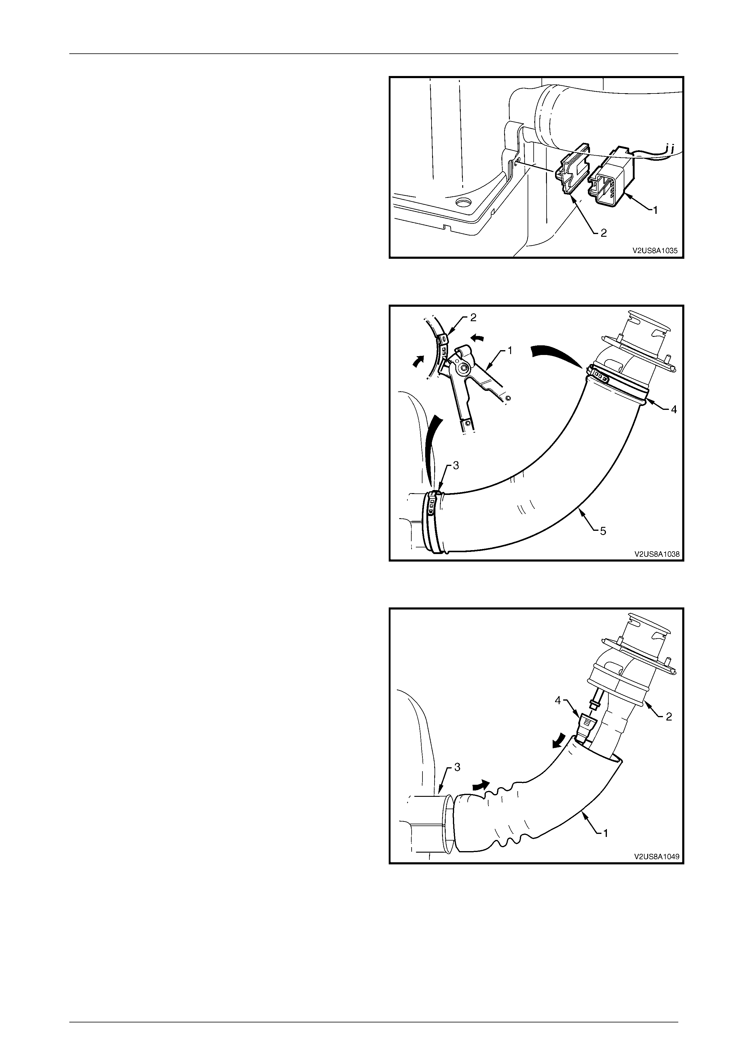
10. Unclip the fuel tank to body wiring harness connector
(1) from its mounting clip (2) which connects onto the
lower plastic fuel tank shell.
Figure 8A1 – 16
11. Using keystone clamp pliers J22610 (1), position the
jaws across the clamp ear (2) and cut through to
release both clamps (3 and 4). Dispose of the used
clamp.
Figure 8A1 – 17
12. Manipulate the santoprene hose (1) off from around the
filler neck flange moulding (2) and down along the fuel
filler neck.
13. Disconnect the fuel tank vapor recirculation line quick
connect fitting (4). If necessary, use special tool AU533
to assist disconnection of quick connect fitting.
14. Manipulate the santoprene hose off from around the
fuel tank cover flange (3).
Figure 8A1 – 18
Fuel and Exhaust Systems Page G-25
Page G-25
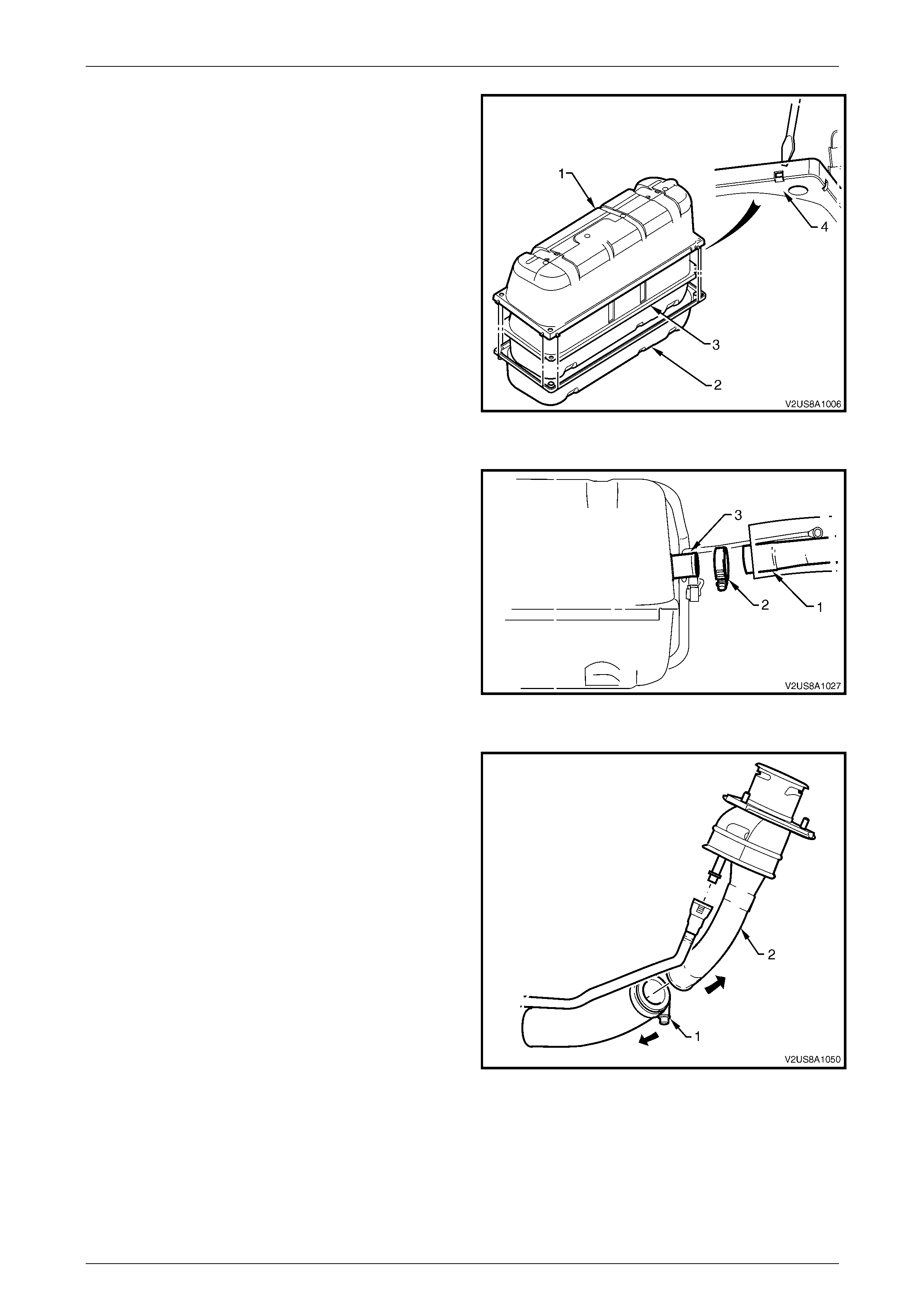
15. Wedge a large flat blade screwdriver in between the
side skirting of each of the upper and lower plastic fuel
tank shells (1 and 2), and pull each of the eight clipping
points (4) free to separate and remove the upper plastic
fuel tank shell as indicated.
16. Lift and remove the fuel tank (3) from the lower plastic
fuel tank shell.
Figure 8A1 – 19
17. If removal of the fuel filler neck assembly is required,
loosen off the fuel tank filler neck throat to fuel filler
neck flexible hose hose-clamp (2) and prise the flexible
hose (1) off from around the fuel tank filler neck
throat (3). Place the fuel filler neck assembly,
santoprene hose and hose-clamp to one side.
18. Plug the fuel tank filler neck throat with a suitable
material to prevent the possibility of foreign objects
entering the fuel tank.
Figure 8A1 – 20
19. If disassembly of the fuel filler neck assembly is
necessary, loosen off the flexible hose to filler neck pipe
hose clamp and pull the flexible hose and filler neck
apart to separate.
20. Cover the fuel tank opening with a suitable material to
prevent foreign objects from entering.
Figure 8A1 – 21
Fuel and Exhaust Systems Page G-26
Page G-26
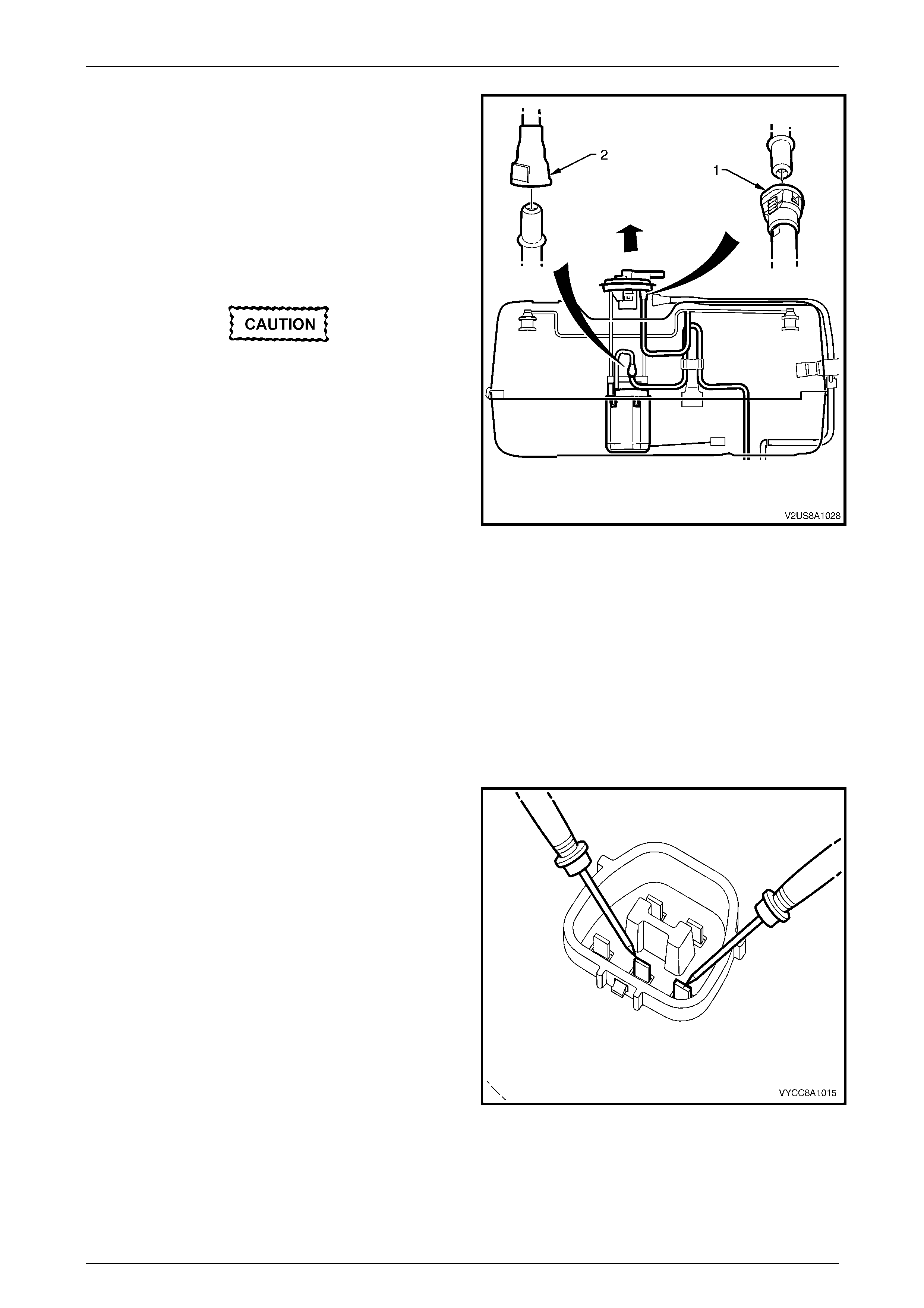
21. Disconnect the fuel tank pressure sensor connector (1),
the fuel pump connector (2) and the EVAP vapor hose
quick connector (3) from the modular fuel pump and
sender assembly cover (4).
22. Cover the EVAP vapor hose quick connect fitting with a
suitable material to prevent foreign objects from
entering.
Figure 8A1 – 22
23. Remove the flanged nut (1) securing the modular fuel
pump and sender assembly earthing terminal (2) to the
fuel tank flange stud (3) and remove the fuel tank wiring
harness.
Figure 8A1 – 23
24. Where necessary, remove the modular fuel pump and sender assembly, refer to
3.6 Modular Fuel Pump And Sender Assembly in this Section.
Fuel vapor remains in the tank even when
completely empty. Seal all openings in the
fuel tank using a suitable plug. Ensure no
naked flames or other ignition sources are
nearby. Ensure all mobile phones and
transmission devices that may cause any
metal objects to become unintentional
receiving antennas are switched off.
Fuel and Exhaust Systems Page G-27
Page G-27
Reinstall
The installation procedure for the fuel tank is the reverse of the removal procedure, noting the following:
1. Tighten the fuel pump and sender assembly earthing terminal nut to the correct torque specification.
Fuel Pump And Sender Assembly
Earthing Terminal Nut
Torque Specification ............................................7.0 Nm
2. When installing the fuel tank assembly into the lower plastic cover, ensure that the EVAP vapor recirculation line
outlet is positioned through the slot provided in the lower cover.
3. Fit each end of the santoprene hose over the fuel tank cover flange and the filler neck flange and locate new ear-
type clamps at each end. Use special service tool keystone clamp pliers J22610 to crimp the clamp ears to fasten.
4. Tighten each of the fuel tank mounting strap upper fastening nuts to the correct torque specification.
Fuel Tank Mounting Strap
Upper Fastening Nut
Torque Specification .............................................20 Nm
5. Tighten each of the fuel tank mounting strap lower fastening nuts to the correct torque specification.
Fuel Tank Mounting Strap
Lower Fastening Nut
Torque Specification .............................................40 Nm
6. If required, tighten the underbody air deflector to vehicle fastening bolts and nuts to the correct torque specification.
Fuel Filler Neck To Filler
Pocket Fastening Nut
Torque Specification ...............................................5 Nm
7. Tighten the three nuts securing the fuel filler neck to the fuel filler pocket to the correct torque specification.
Fuel Filler Neck To Filler
Pocket Fastening Nut
Torque Specification ...............................................5 Nm
8. Fully install the fuel filler cap onto the fuel filler neck.

Fuel and Exhaust Systems Page G-28
Page G-28
3.5 Fuel Filler Neck Assembly
To avoid the possibility of fuel spillage in the rear compartment, removal of the fuel filler neck assembly on its own is not
recommended. Removal and disassembly of the fuel filler neck assembly from the fuel tank forms part of the fuel tank
removal procedure, refer to 3.4 Fuel Tank Assembly, in this Section.
Fuel and Exhaust Systems Page G-29
Page G-29
3.6 Modular Fuel Pump And Sender
Assembly
Remove
Ensure no naked flames or other ignition
sources are nearby. Ensure mobile phones
(and transmission devices that may cause any
metal objects to become unintentional
receiving antennas) are switched off.
Wear safety glasses when using compressed
air. Do not blow compressed air directly onto
any body part.
NOTE
Before proceeding with removal of the modular
fuel pump and sender assembly, clean all traces
of dirt and other foreign material from the top of
the fuel tank, near the modular fuel pump and
sender assembly. Also, use compressed air to
ensure that all dirt and foreign materials are
removed from all relevant fuel system connectors
before disconnection.
NOTE
Full removal of the fuel tank from the vehicle is
recommended for this service procedure so as to
reduce the risk of fuel spillage within the rear
luggage compartment.
Fuel and Exhaust Systems Page G-30
Page G-30
1. Remove the fuel tank assembly from the vehicle to gain
access to the modular fuel pump and sender assembly
and remove the top fuel tank shell, refer to
3.4 Fuel Tank Assembly, in this Section.
2. Disconnect the fuel tank pressure sensor connector, the
fuel pump connector and the EVAP vapor hose quick
connector from the modular fuel pump and sender
assembly cover, refer to
3.4 Fuel Tank Assembly, in this Section.
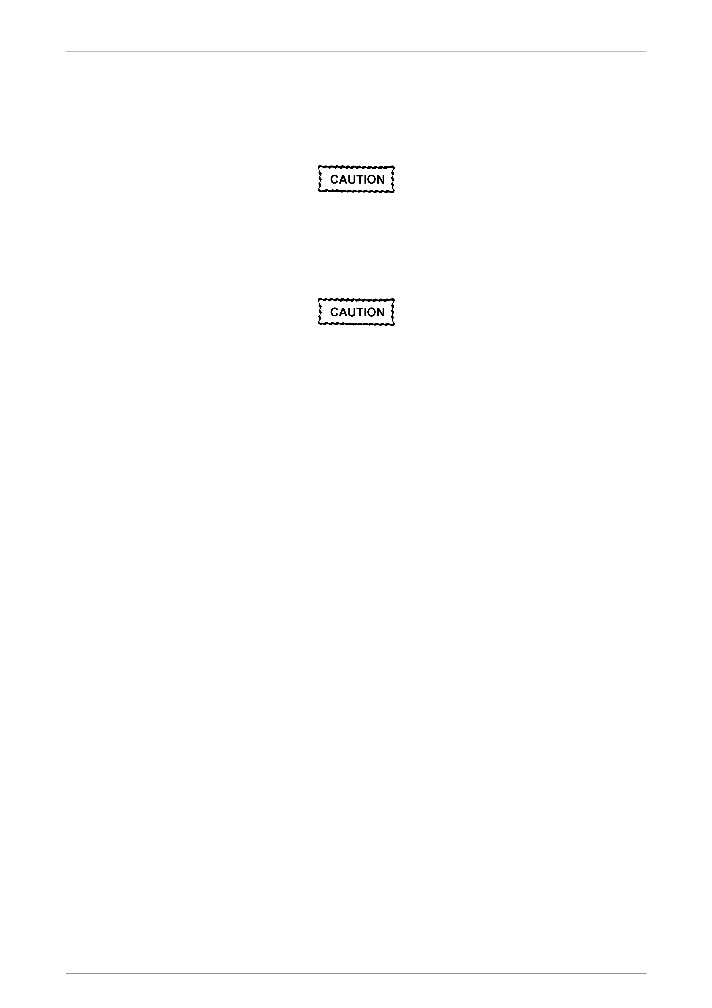
The modular fuel pump and sender assembly
cover springs up when the retainer is
removed.
3. Using the lock ring removal tool J45722 (1) and a half-
inch breaker bar (2), remove the cover retainer lock
ring (3) by turning in an anti-clockwise direction.
NOTE
Ensure that the lock ring removal tool is correctly
installed onto the lock ring as significant removal
torque is required to overcome the positive
locking feature of the lock ring. Where necessary,
use a breaker bar extension to aid removal.
NOTE
Assistance will be required to hold the tank in
position during this procedure.
Figure 8A1 – 24
Fuel and Exhaust Systems Page G-31
Page G-31
4. Partially lift the modular fuel pump and sender
assembly away from the fuel tank, taking care not to
damage the fuel level sender assembly. Disconnect the
fuel tank EVAP vapor line quick connector (1) from the
underside of the modular fuel pump and sender
assembly cover. If necessary, use special service tool
AU533 to assist disconnection.
5. Insert hand into the fuel tank opening and disconnect
the fuel feed line quick connector (2).
6. Remove the modular fuel pump and sender assembly.
The reservoir will be full of fuel. When the
modular fuel pump and sender assembly is
removed from the fuel tank, pour any
remaining fuel in the reservoir into a suitable
container. Never siphon or store fuel into an
open container, due to the possibility of fire or
explosion.
NOTE
Fuel vapor remains in the tank even when
completely empty. Seal the opening in the fuel
tank using a suitable plug and place a suitable
cover over the plug to prevent any foreign matter
from entering.
7. Remove and discard the modular fuel pump and sender
assembly to fuel tank seal.
8. Check the underside of the reservoir to ensure that
there are three rubber isolator feet attached to the
bottom. If one or more are missing, retrieve each from
within the fuel tank and reinstall.
Figure 8A1 – 25
Test
1. Measure the resistance across the fuel level sender
terminals of the modular fuel pump and sender
assembly cover connector. Take the following
measurements:
a. With the fuel level sender assembly rotated in the
full position, the resistance should be 40 ohms
(+/– 2.5 ohms).
b. With the fuel level sender assembly in the full
position, the resistance should be 248 ohms
(+/- 3.5 ohms).
2. If the fuel level sender assembly resistance for either of
these settings is not as specified, replace the complete
fuel level sender assembly with a serviceable item.
Figure 8A1 – 26
Fuel and Exhaust Systems Page G-32
Page G-32
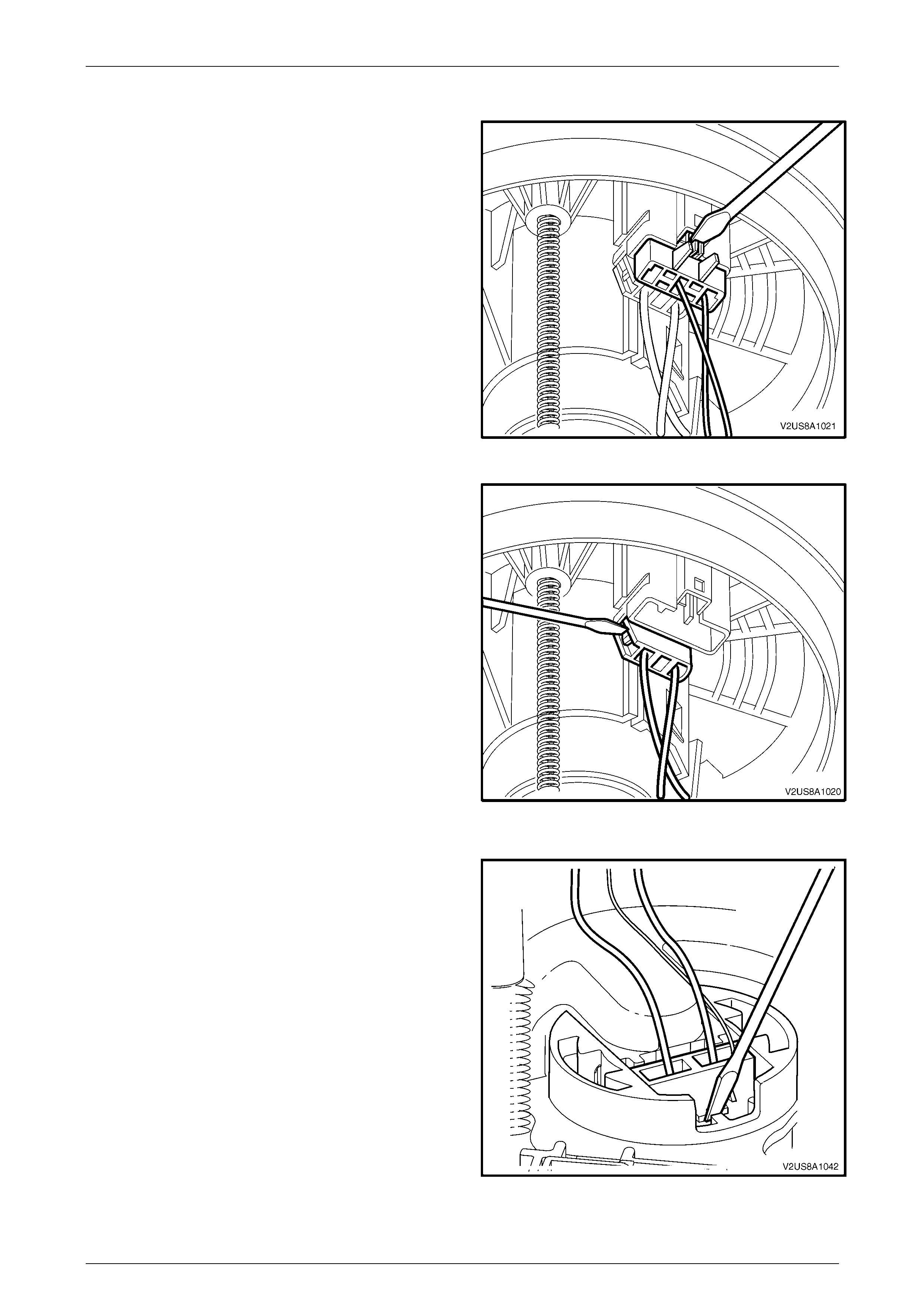
Disassemble
1. Use a flat blade driver to assist removal of the fuel level
sender assembly harness connector from underneath
the modular fuel pump and sender assembly cover as
indicated.
Figure 8A1 – 27
2. Use a flatblade driver to assist removal of the fuel pump
harness connector from underneath the modular fuel
pump and sender assembly cover as indicated.
Figure 8A1 – 28
3. Press in the tang retaining the fuel pump connector on
the fuel pump and filter assembly, then remove the
connector.
Figure 8A1 – 29
Fuel and Exhaust Systems Page G-33
Page G-33
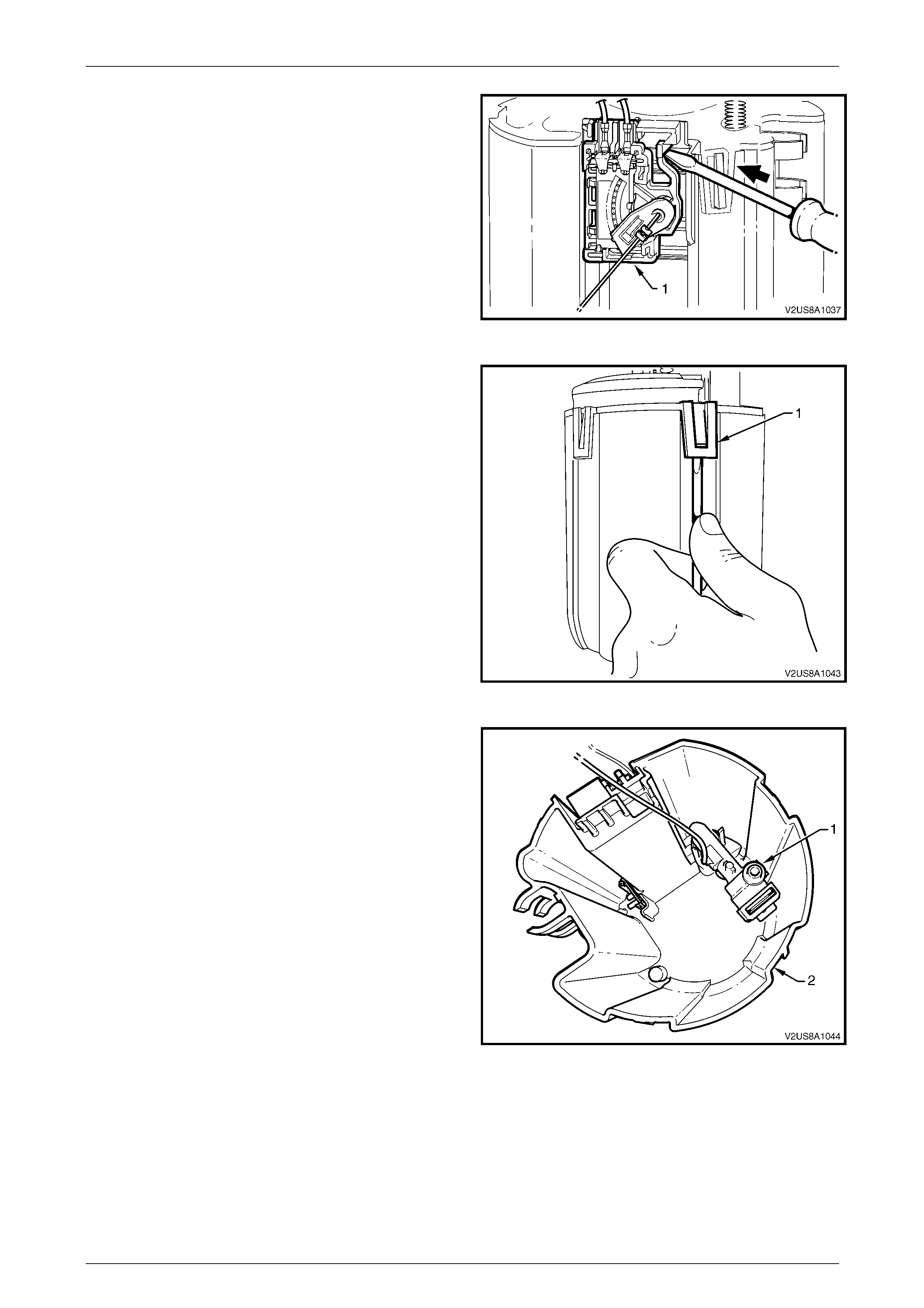
4. Prise the tang open that holds the fuel level sender
assembly (1) to the side of the reservoir, then lift it off
from the reservoir.
Figure 8A1 – 30
5. Prise each of the four tangs (1) with a flat-bladed
screwdriver, then remove the motor and filter assembly,
and cover from the reservoir.
NOTE
Another person may be required to assist in
removing the motor and filter assembly from the
reservoir.
6. Pull the modular fuel pump and sender assembly cover,
motor and filter assembly from the reservoir body.
Figure 8A1 – 31
7. Remove the fuel pressure regulator holder (1) from the
reservoir assembly (2).
NOTE
Some difficulty may be experienced when lifting
these items from the reservoir body due to the
limited space available.
NOTE
Ensure the O-ring is removed from the base of the
reservoir.
Figure 8A1 – 32
Fuel and Exhaust Systems Page G-34
Page G-34
8. Prise open both tangs securing the fuel outlet
connector (1) to the bottom of the motor and filter
assembly (2), then remove the fuel outlet pipe from the
motor and filter assembly.
NOTE
Ensure the O-ring is removed from within the
motor and filter assembly female connector
moulding.
Figure 8A1 – 33
9. Push the motor and filter assembly down the sprung
shafts and remove the circlip (only one shaft is fitted
with a circlip) from the end of the shaft. Place the circlip
in a safe location away from the immediate worksite.
Figure 8A1 – 34
Fuel and Exhaust Systems Page G-35
Page G-35
Reassemble
The procedure for reassembling the modular fuel pump and sender assembly is the reverse of the disassembly
procedure, noting the following:
1. Locate and push the motor and filter assembly down the sprung shafts, then press the circlip into the slot provided
at the tip of one of the shafts.
NOTE
Refer to Figure 8A1 – 35 for the correct
orientation of the motor and filter assembly, and
the cover.
2. Locate and press the fuel outlet connector (1) to its
position on the bottom of the motor and filter assembly
so that it clips firmly into place, refer to Figure 8A1 – 33.
3. Fit a new pressure regulator O-ring (5) into place over
the pressure regulator holders reservoir jet pump port,
refer to Figure 8A1 – 41, and firmly press the pressure
regulator holder into position inside the reservoir, refer to
Figure 8A1 – 32.
4. Position the motor and filter assembly with the cover
attached back into the reservoir and press to clip
together each of the four tangs (1), refer to
Figure 8A1 – 31.
NOTE
Ensure the wires to the fuel level sender
assembly, pressure regulator and both connectors
do not interfere when reassembling the motor and
filter assembly into the reservoir.
5. Locate and press the ceramic variable resistor card and
holder assembly to lock to its position on the reservoir,
refer to Figure 8A1 – 30.
6. Locate and press each of the fuel pump harness
connectors to their positions on the top of the motor and
filter assembly, and on the underside of the modular fuel
pump and sender assembly cover, refer to
Figure 8A1 – 29 and Figure 8A1 – 28 respectively.
7. Locate and press the fuel level sender assembly
harness connector to its position on the underside of
the modular fuel pump and sender assembly cover,
refer to Figure 8A1 – 27.
Figure 8A1 – 35
Reinstall
The procedure for reinstalling the modular fuel pump and sender assembly is the reverse of the removal procedure,
noting the following:
NOTE
Upon installation of the modular fuel pump and
sender assembly, only use the custom sized O-
rings as supplied with modular fuel pump and
sender assembly replacement parts kit. Do not
use off-the-shelf O-rings. Refer to 3.11 Modular
Fuel Pump And Sender Assembly O-Rings for O-
ring specifications.
Fuel and Exhaust Systems Page G-36
Page G-36
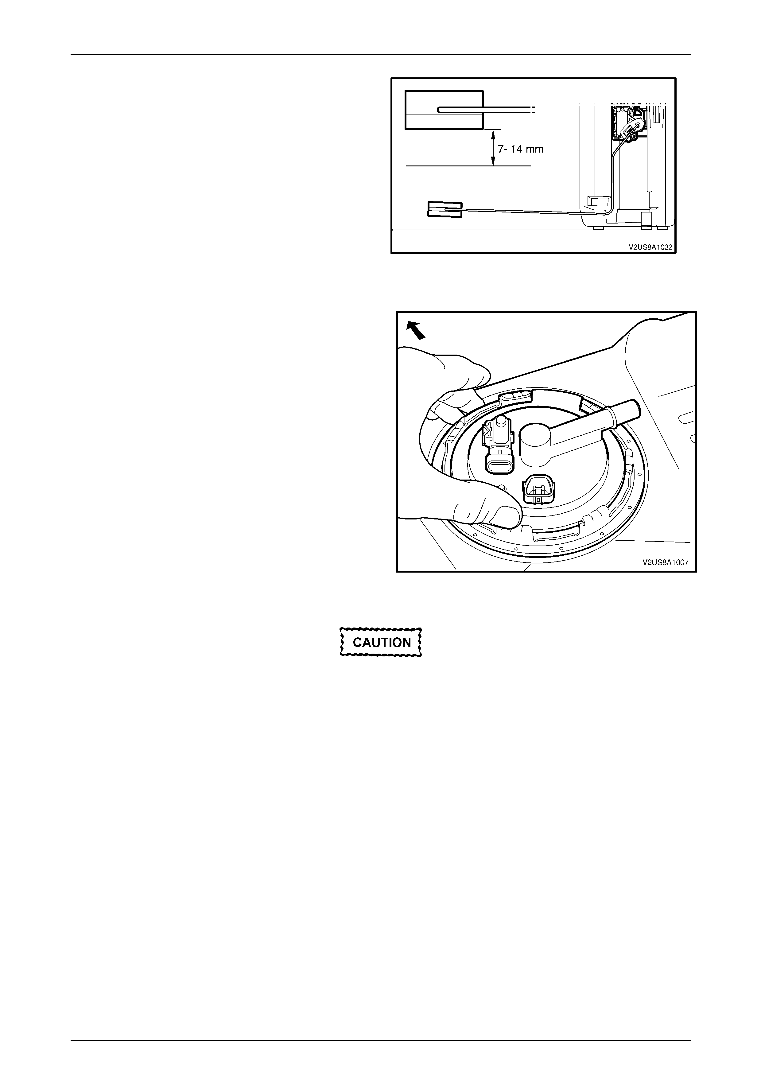
1. Before installation into the fuel tank, check the fuel
sender float position as follows:
a. Stand the assembly upright on a flat surface.
b. Measure the distance between the middle of the fuel
sender float and the flat surface.
c. If required, the float position should be corrected,
through careful adjustment of the float arm, to
achieve a nominal measurement of between 7 mm
and 14 mm.
2. Clean any dirt and foreign materials from the fuel tank
seal recess and position a new seal (3) in the recess,
refer to Figure 8A1 – 2.
3. Install the modular fuel pump and sender assembly into
the fuel tank, taking care not to damage the fuel level
sender float and arm in the process. Figure 8A1 – 36
4. Ensure the locator in the cover engages in the slot in
the tank opening.
Figure 8A1 – 37
Incorrect installation of the modular fuel
pump and sender assembly retainer could
lead to fuel vapor leakage. Take special care
and ensure that the lock ring is installed
correctly.
5. Install the cover retainer lock ring. Use the half-inch breaker bar with special tool J45722 and rotate the retainer in a
clockwise direction until the tangs are engaged.
6. Install the fuel tank pressure sensor connector (1), the fuel pump connector (2) and the EVAP vapor hose quick
connector (3) to the modular fuel pump and sender assembly cover (4), refer to Figure 8A1 – 22.

Fuel and Exhaust Systems Page G-37
Page G-37
3.7 Fuel Level Sender Assembly
The fuel level sender assembly is serviced as a complete assembly and attaches to the side of the modular fuel pump
and sender assembly reservoir. Testing, removal and reinstallation of the fuel level sender assembly are contained within
the modular fuel pump and sender assembly service procedures,
refer to 3.6 Modular Fuel Pump And Sender Assembly.
Fuel and Exhaust Systems Page G-38
Page G-38
3.8 Modular Fuel Pump And Strainer
Assembly
The modular fuel pump and strainer assembly is contained within the fuel filter assembly.
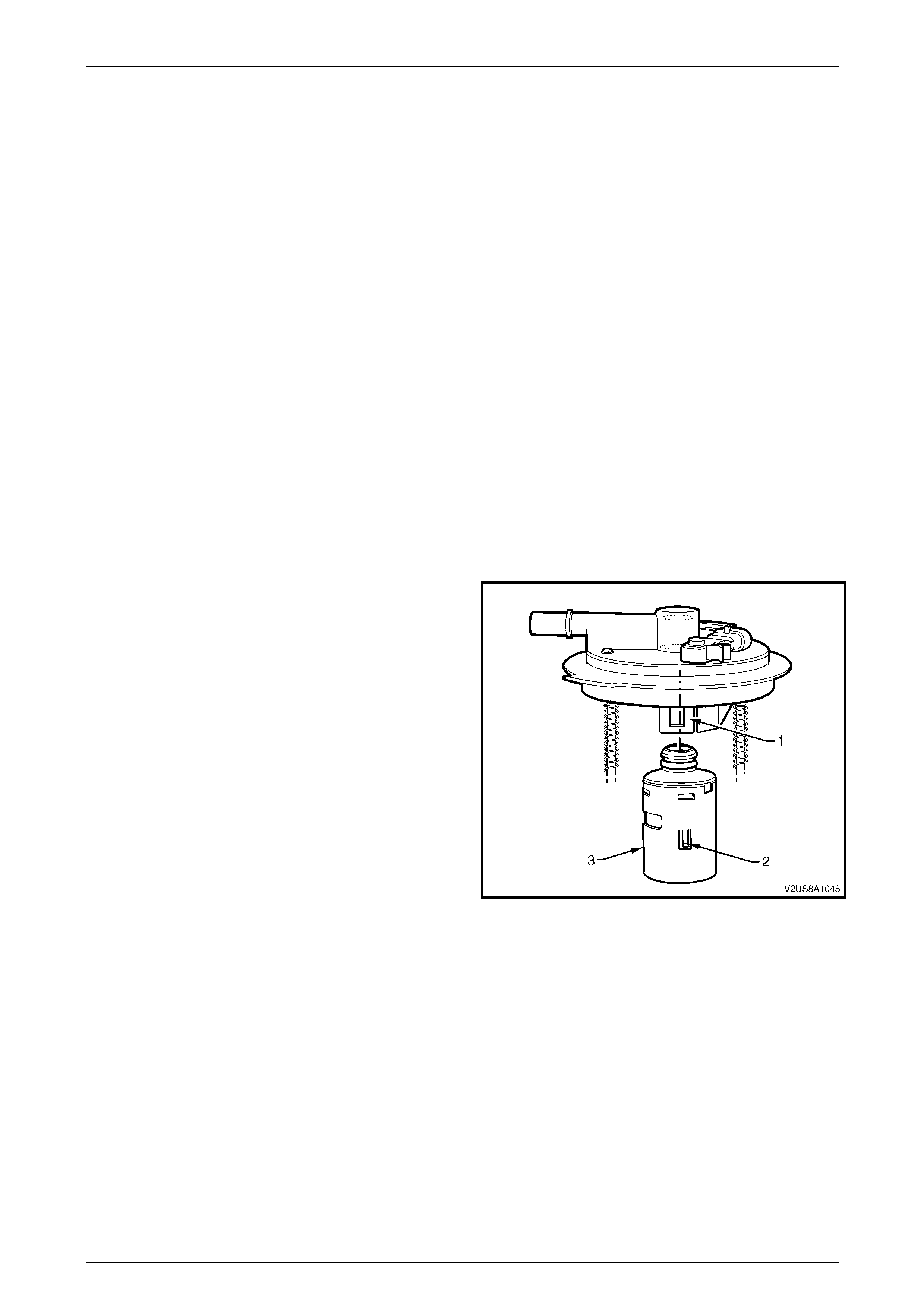
Remove
1. Remove and disassemble the modular fuel pump and sender assembly to access the fuel pump and strainer
assembly, refer to 3.6 Modular Fuel Pump And Sender Assembly.
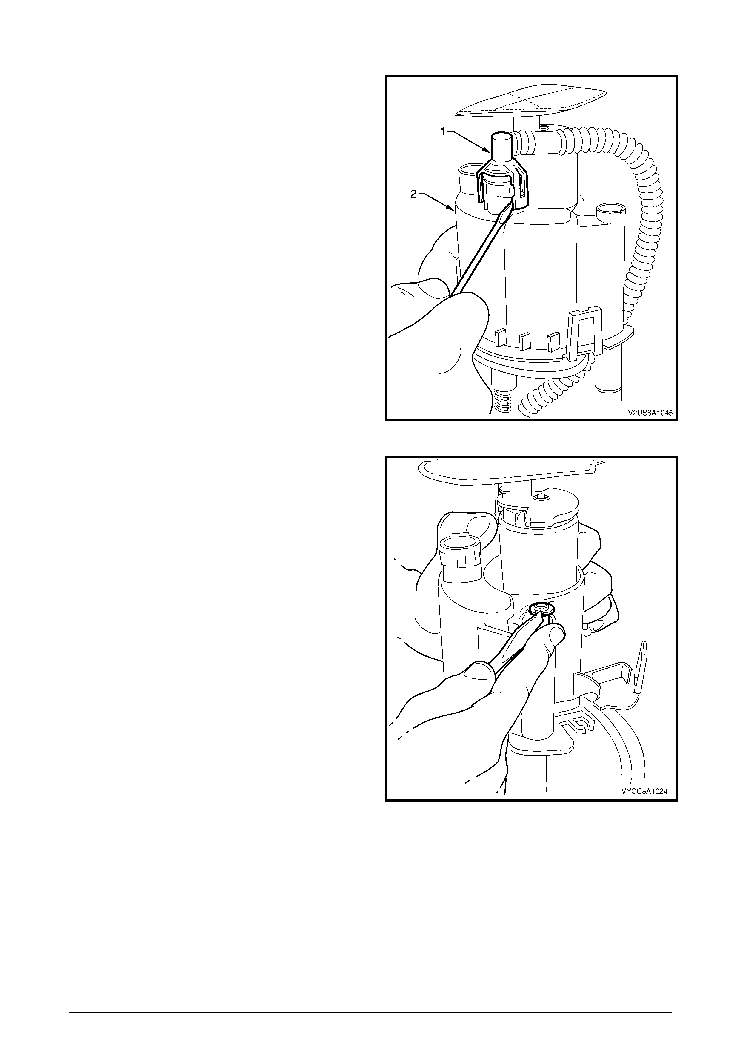
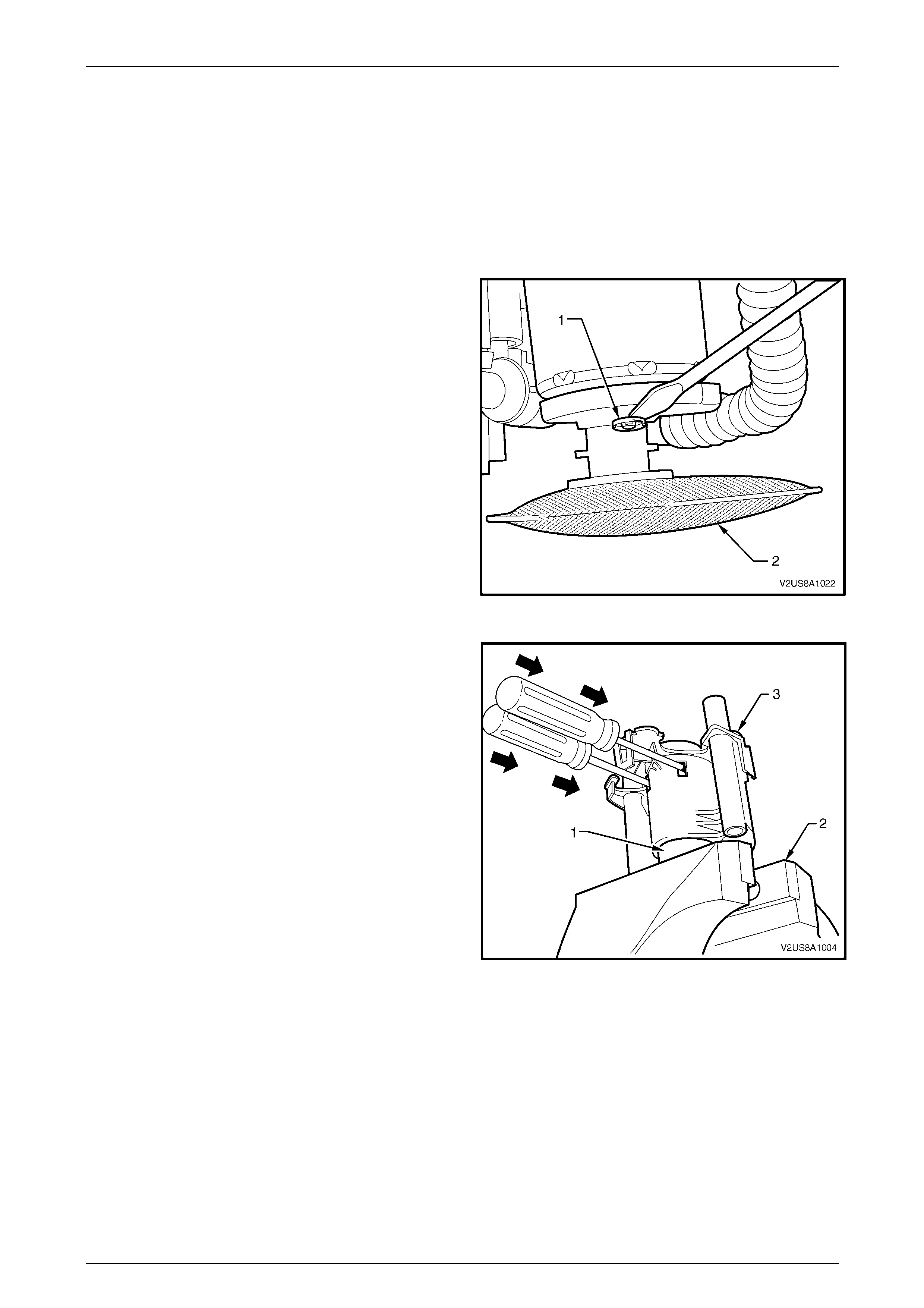
2. Using a suitable blade or a flat-bladed screwdriver,
remove the 'easy washer' (1) from the fuel pump end cap
post.
3. Remove the suction filter (2).
Figure 8A1 – 38
NOTE
Do not over tighten the vice grips as this may
damage the fuel pump.
4. Clamp the protruding end of the modular fuel pump (1)
in a soft jawed vice (2) to support the fuel filter and
pump assembly (3) in place.
5. Insert a pair of medium sized flat bladed screwdrivers
through each of the service holes in the fuel filter
assembly and firmly slide the blade between the fuel
pump end cap and the internal fuel filter clips that hold
the fuel pump in place.
Figure 8A1 – 39
Fuel and Exhaust Systems Page G-39
Page G-39
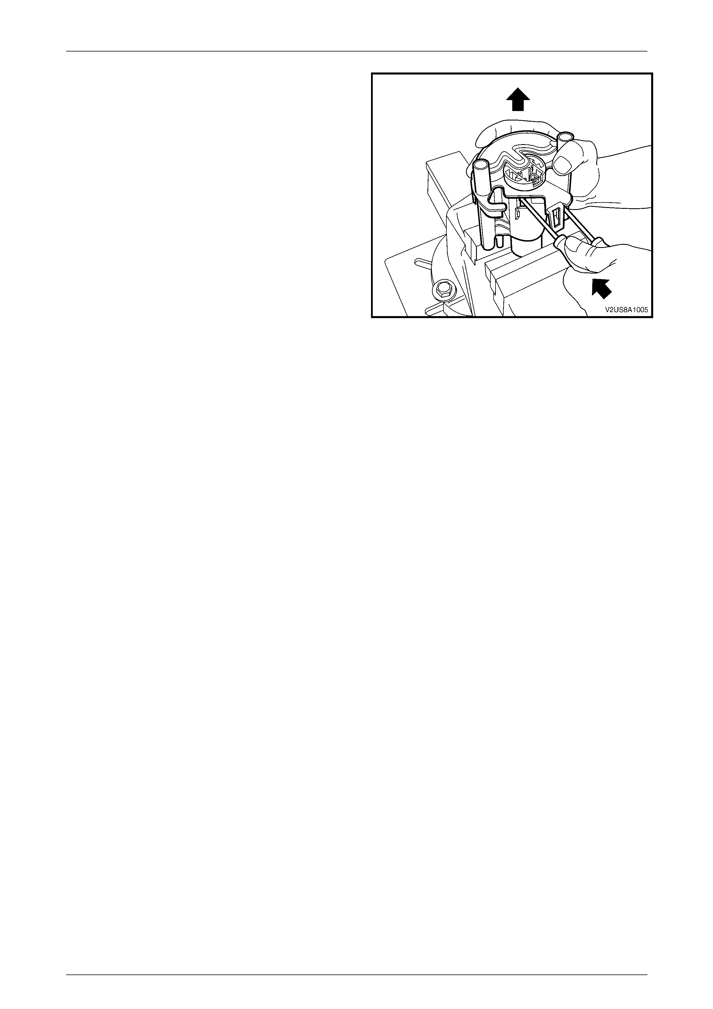
6. Push the screwdrivers in far enough so that the internal
fuel filter clips are deflected just free of each of the fuel
pump end cap retainer shoulders.
7. Whilst holding the screwdrivers in place with one hand,
manipulate the fuel filter assembly in an upward
direction to separate it from the fuel pump.
Figure 8A1 – 40
Reinstall
The procedure for reinstallation of the fuel pump and strainer assembly is the reverse of the removal procedure noting
the following:
NOTE
Check the 'easy washer' for serviceability and
replace if necessary.
NOTE
Upon installation of the modular fuel pump and
strainer assembly, only use the custom sized
O-rings as supplied with fuel pump and strainer
assembly replacement parts kit. Do not use off-
the-shelf O-rings. Refer to 3.11 Modular Fuel
Pump And Sender Assembly O-Rings for O-ring
specifications.
1. Ensure the 'easy washer' is firmly installed along the fuel pump end cap post and firmly pressed up against the
suction filter moulding.
2. Using hands only, locate the fuel pump in its correct orientation into the fuel filter.
3. Push the fuel pump firmly into place and lock the fuel pump into the fuel filter.

Fuel and Exhaust Systems Page G-40
Page G-40
3.9 Fuel Filter Assembly
The fuel filter is contained within the modular fuel pump and sender assembly and forms the moulded housing for the fuel
pump. The fuel filter is accessible upon removal of the modular fuel pump from the modular fuel pump and strainer
assembly, refer to 3.8 Modular Fuel Pump And Strainer Assembly in this Section.
NOTE
Upon installation of the fuel filter assembly, only
use the custom sized O-rings as supplied with
fuel filter assembly replacement parts kit. Do not
use off-the-shelf O-rings. Refer to 3.11 Modular
Fuel Pump And Sender Assembly O-Rings for O-
ring specifications.
Fuel and Exhaust Systems Page G-41
Page G-41
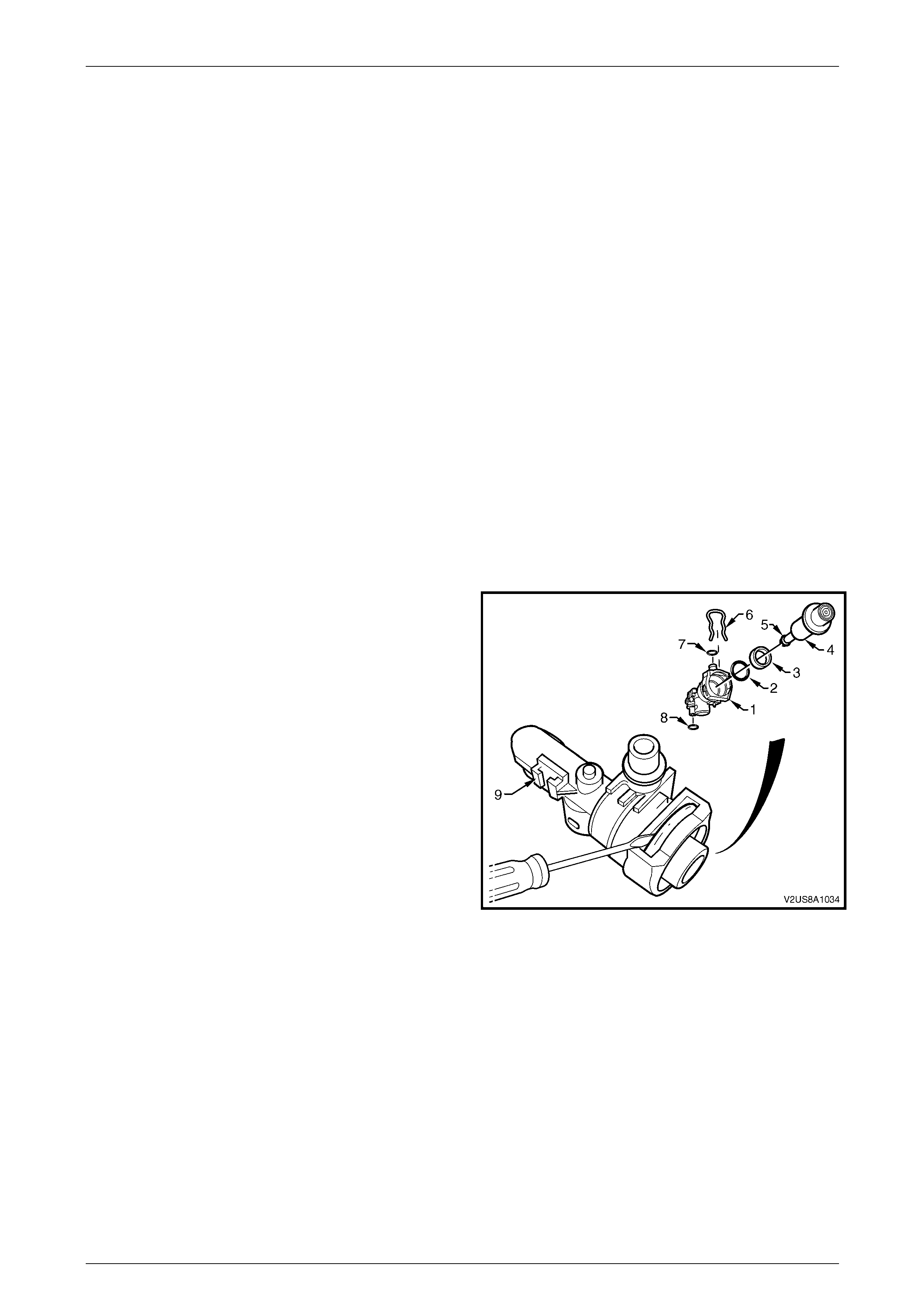
3.10 Fuel Pressure Regulator
Remove
NOTE
Refer to 2.1 General Information in this Section
for O-ring service part specifications.
1. Remove the modular fuel pump and sender assembly from the fuel tank and remove the modular fuel pump and
sender assembly cover from the reservoir to access and remove the fuel pressure regulator holder, refer to the
disassemble procedure within 3.6 Modular Fuel Pump And Sender Assembly.
NOTE
Removal of the fuel pressure regulator can be
achieved without disassembly and removal of the
fuel level sensor assembly or disconnection of the
fuel pump motor or fuel level sensor patch wiring
harness connectors.
NOTE
Do not bend the earthing terminal on the pressure
regulator holder; this can be easily damaged or
broken.
2. Remove the copper earthing terminal attached to the
terminal connector moulding (9) of the pressure
regulator holder using a pair of pointy nose pliers.
3. Remove the retaining clip (6) from the top of the
pressure regulator holder and place in a safe location
away from the immediate worksite.
4. Using a flat-bladed screwdriver, prise the pressure
regulator (4) from the pressure regulator holder (1).
5. If necessary, remove the nylon spacer (3) and remove
and tag the regulator to holder O-ring (2).
6. If necessary, remove and tag the fuel filter to pressure
regulator holder O-ring (7), the pressure regulator
holder to reservoir jet pump O-ring (8) and the fuel
pressure regulator O-ring (5) and place in a safe
location away from the immediate worksite.
Figure 8A1 – 41
Reinstall
The procedure for reinstallation of the pressure regulator is the reverse of the removal procedure noting the following:
NOTE
Upon installation of the fuel pressure regulator,
only use the custom sized O-rings as supplied
with fuel pressure regulator replacement parts kit.
Do not use off-the-shelf O-rings. Refer to
3.11 Modular Fuel Pump And Sender Assembly
O-Rings for O-ring specifications.
Fuel and Exhaust Systems Page G-42
Page G-42
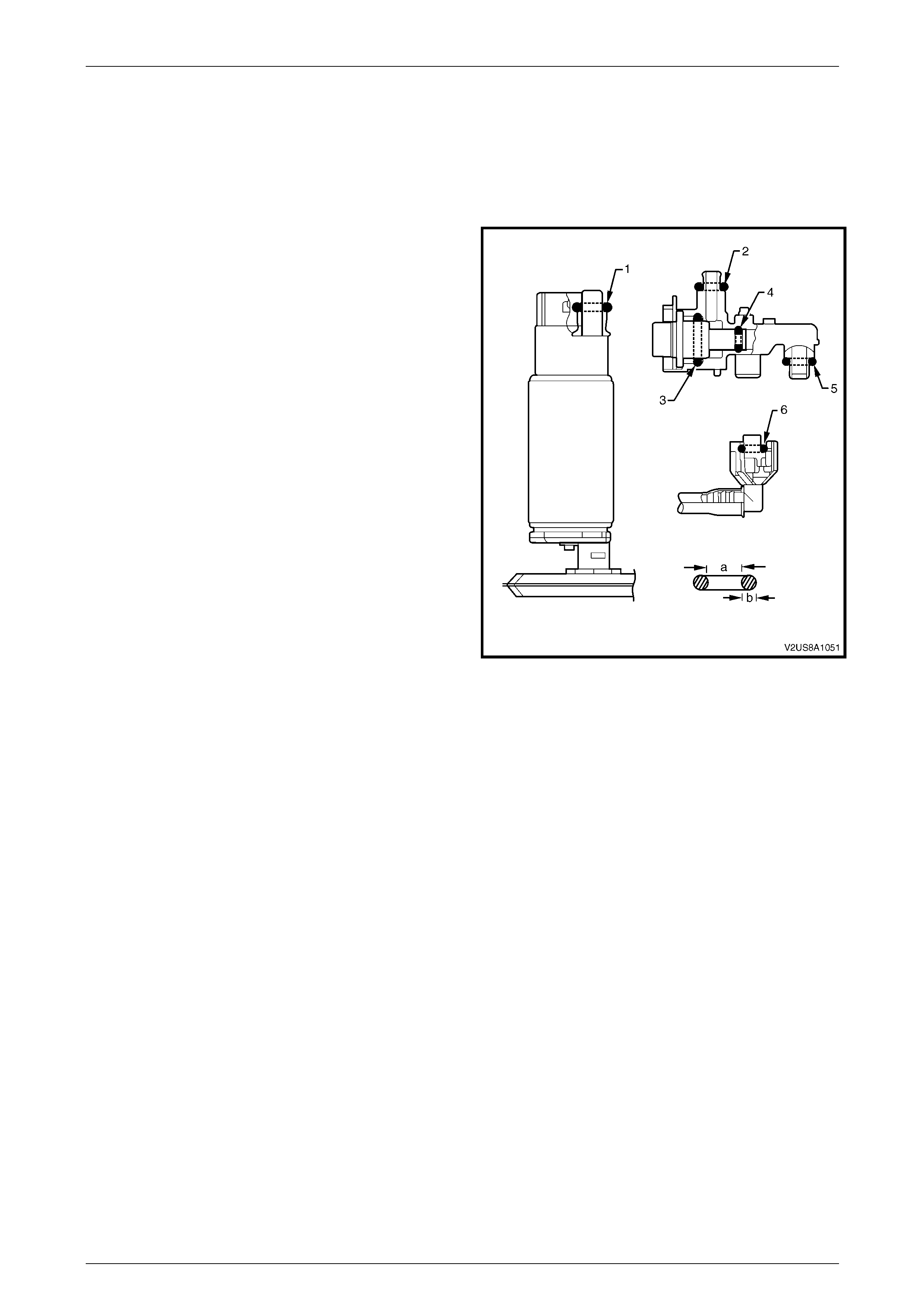
3.11 Modular Fuel Pump And Sender
Assembly O-Rings
O-rings seal various connections in the modular fuel pump and sender assembly and are made of a special material.
Always service the O-ring seals with the correct service part as provided with the service kit. Refer to Figure 8A1 – 42 to
identify O-ring service part specifications.
O-RING SPECIFICATIONS
O-RING a (mm) b (mm)
1 8.20 3.50
2 7.52 3.53
3 15.4 2.90
4 4.25 2.60
5 8.20 3.50
6 8.20 3.50
7 8.20 3.50
Figure 8A1 – 42
Fuel and Exhaust Systems Page G-43
Page G-43
3.12 Fuel Tank Pressure Sensor
The fuel tank pressure sensor is press fitted to the modular fuel tank and sender assembly cover. To access the fuel tank
pressure sensor for service purposes, full removal of the fuel tank from the vehicle is recommended. For information on
fuel tank pressure sensor and fuel tank leak test diagnostics, refer to Section 6C3-2C Functional Checks in the MY2003
VY & V2 II Series Service Information.
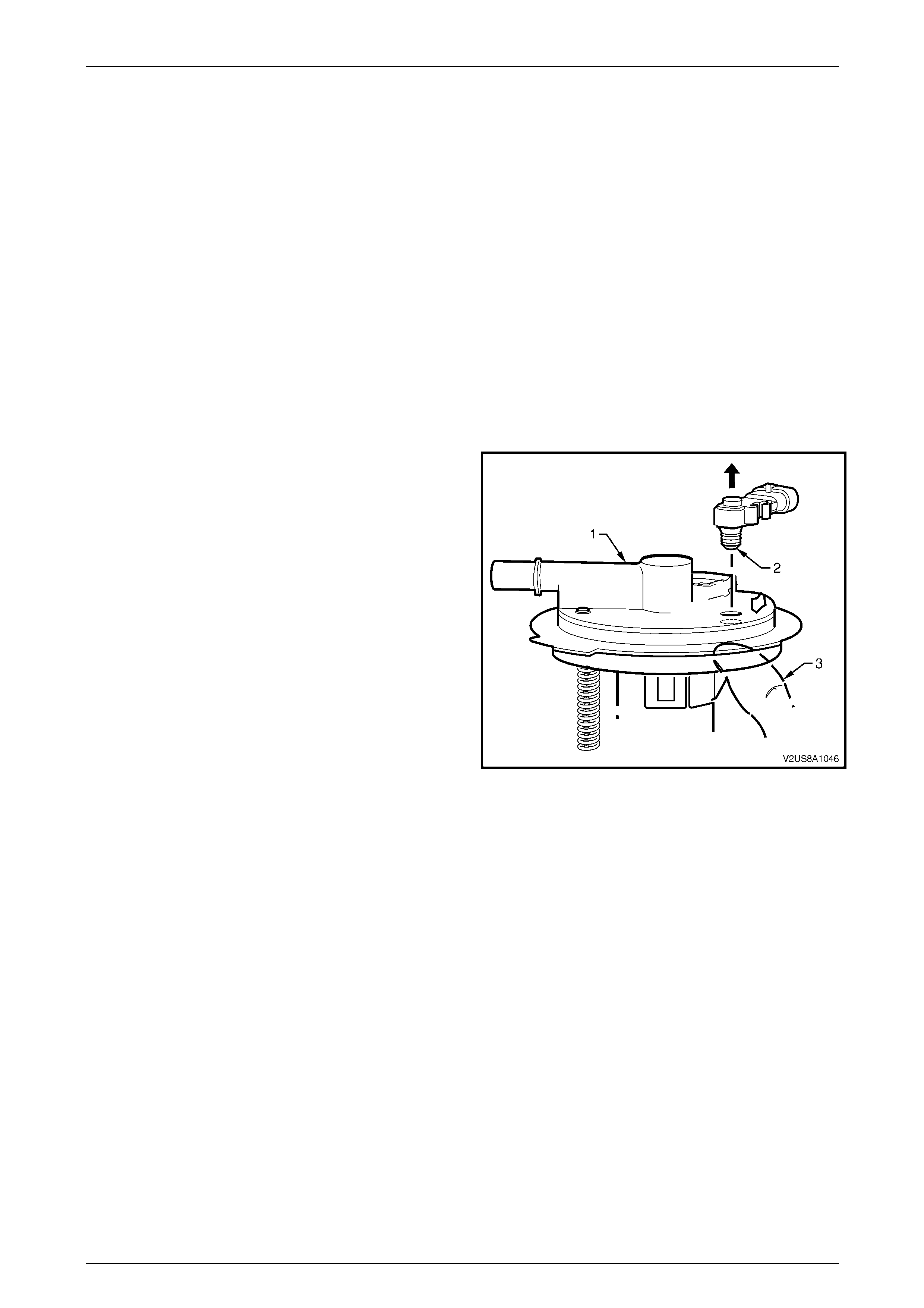
Remove
1. Remove the fuel tank assembly from the vehicle and remove the modular fuel pump and sender assembly from the
fuel tank to access the fuel tank pressure sensor, refer to 3.6 Modular Fuel Pump And Sender Assembly.
NOTE
Removal of the fuel pressure regulator can be
achieved without disassembly and removal of the
fuel level sensor assembly or disconnection of the
fuel pump motor or fuel level sensor patch wiring
harness connectors.
NOTE
Do not pull or lever the fuel pressure sensor out
from the connector end as damage the may occur
to the sensor body.
2. Grasp the modular fuel pump and sender assembly
cover (1) in hand and from the underside, apply thumb
pressure (3) to the opening port (2) of the fuel tank
pressure sensor. To aid removal, pull the head of the
sensor body directly outwards from the cover.
Figure 8A1 – 43
Reinstall
Installation of the fuel tank pressure sensor is the reverse of the removal procedure, noting the following:
1. Check the rubber seal around the collar of the pressure sensor opening port (2) for damage and replace complete
pressure sensor assembly if necessary, refer to Figure 8A1 – 43.
2. Align the fuel tank pressure sensor with the opening port and guide support of the modular fuel pump and sender
assembly cover, and press firmly into place.
Fuel and Exhaust Systems Page G-44
Page G-44
3.13 Fuel Fill Limiter Vent Valve Assembly
(FLVV)
The fill limiter vent valve assembly is clipped into the underside of the modular fuel pump and sender assembly cover. To
access the fill limiter vent valve assembly for service purposes, full removal of the fuel tank from the vehicle is
recommended.
NOTE
The fill limiter vent valve assembly is serviced as
a complete assembly, and as such, should not
require further disassembly upon removal from
the modular fuel pump and sender assembly.
Remove
1. Remove the fuel tank assembly from the vehicle and remove the modular fuel pump and sender assembly from the
fuel tank to access the fill limiter vent valve, refer to 3.6 Modular Fuel Pump And Sender Assembly.
NOTE
Removal of the fill limiter vent valve can be
achieved without disassembly and removal of the
fuel level sender assembly or disassembly of the
fuel pump motor or fuel level sender patch wiring
harness connectors.
2. Lever each of the two modular fuel pump and sender
assembly cover tangs (1) clear of the vent valve
locators (2) whilst pulling the fill limiter vent valve
assembly (3) out to remove. If necessary, use a flat
blade screwdriver to assist leverage of the tangs.
Figure 8A1 – 44
Reinstall
Installation of the fuel limiter vent valve assembly is the reverse of the removal procedure, noting the following:
1. Align the fill limiter vent valve into the modular fuel pump and sender assembly cover and press firmly to click into
place.
Fuel and Exhaust Systems Page G-45
Page G-45
3.14 Fuel Filler Cap
The fuel filler cap is a 'screw on' type, with an integrated tightening torque limiting mechanism. When installing the cap,
tighten it until a ratcheting (clicking) sound is heard, indicating the cap is properly tightened. The fuel tank filler cap is
tethered to the fuel filler pocket. The fuel tank filler cap requires a quarter of a turn in order to be removed.
If a fuel tank filler cap requires replacement,
use only a fuel tank filler cap with the same
features. Failure to use the correct fuel tank
filler cap can result in a serious malfunction
of the emission control system.
Remove
1. Untwist and remove the fuel filler cap (1) from the fuel
filler neck opening.
2. Use a flat blade screwdriver to prise the fuel filler cap
tether line fastener (2) from its mounting hole.
3. Plug the fuel filler opening with a suitable material to
prevent the possibility of foreign material entering into
the fuel tank.
Figure 8A1 – 45
Reinstall
Installation of the fuel filler cap is the reverse of the removal procedure, noting the following:
NOTE
Check the fuel filler cap for serviceability and
replace where necessary.

Fuel and Exhaust Systems Page G-46
Page G-46
4 Specifications
Fuel Tank Capacity:.............................................................................70 litres
Fuel Tank Material:.............Pressed steel with high density polyethylene shell
Fuel Filler Location:...........................................Right-hand rear quarter panel
Fuel Pump Type:.......................................................................Single Turbine
Pressure Regulator Location: Inside modular fuel pump and sender assembly
Fuel Pump Location:..............Inside modular fuel pump and sender assembly
Fuel Pump Regulated Pressure:.......................................400 kPa (+/– 3 kPa)
Minimum Fuel Pump Flow Capacity
(at regulated pressure):..............................................2.95 L/min @ 13.5 volts
..................................................2.33 L/min @ 12 volts
Fuel Pump Current Draw
(steady state at regulated pressure):..............................11.0 Amps maximum

Fuel and Exhaust Systems Page G-47
Page G-47
5 Torque Wrench Specifications
Fuel Tank Mounting Strap Nut - Upper...............................................20.0 Nm
Fuel Tank Mounting Strap Nut - Lower...............................................40.0 Nm
Canister Mounting Nut.................................................................5.0 – 8.0 Nm
Fuel Filler Neck to Filler Pocket Mounting Nut......................................5.0 Nm
Modular Fuel Pump and Sender Assembly Earthing
Terminal to Fuel Tank Stud Flanged Earthing Nut................................7.0 Nm
Stone Guard Securing Bolt..........................................................5.0 – 7.0 Nm
Stone Guard Securing Nut ..........................................................1.5 – 2.5 Nm
Fuel and Exhaust Systems Page G-48
Page G-48
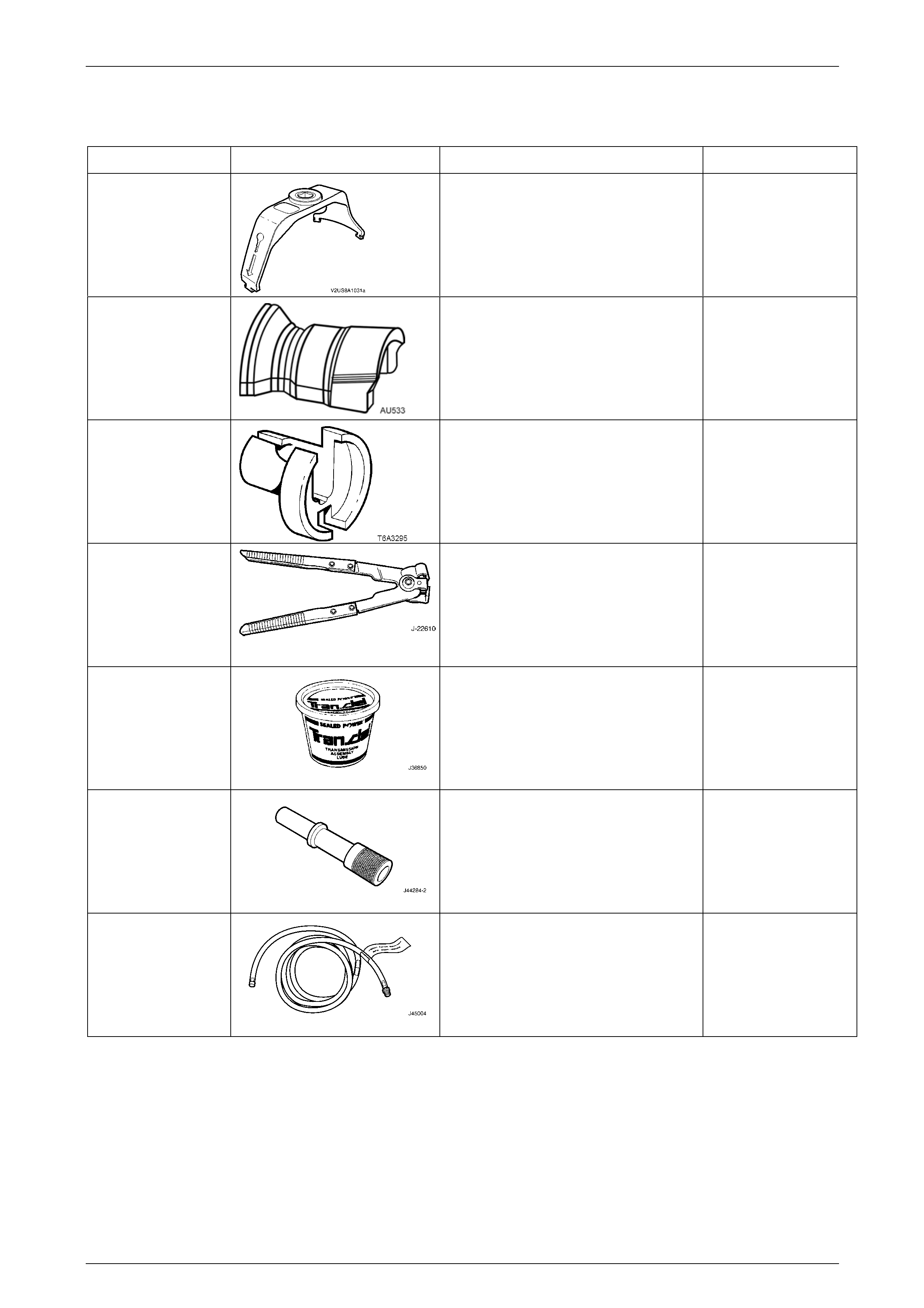
6 Special Tools
TOOL NUMBER ILLUSTRATION DESCRIPTION CLASSIFICATION
J45722
MODULAR FUEL PUMP AND
SENDER ASSEMBLY LOCKING RING
REMOVE AND INSTALL TOOL
Used to provide positive holding of fuel
tank lock ring for removal and
installation with 1/2 inch breaker bar.
Mandatory
AU533
QUICK-CONNECT FITTI NG RELEASE
TOOL
Released in two sizes; Red for
5/16-inch fittings and Blue for 3/8-inch
fittings.
Also available commercially
Desirable
7371 QUICK-CONNECT RELEASE TOOL –
3/8-INCH
Used for releasing fuel hose quick
connects at the dash panel and fuel rail
connections, after the fuel system has
been depressurised.
Mandatory
J22610 KEYSTONE CLAMP PLIERS
Used to remove and fasten ear-type
clamps.
Available
J36850
TRANSJEL LUBRICANT
Used to lubricate fuel tank siphon hose
during fuel tank drain/siphon
procedures.
Desirable
J44284-2
FUEL FLAPPER DOOR HOLDER
Holds open fuel filler neck flapper door
to allow fuel tank siphon hose to be fed
down into fuel filler neck.
Mandatory
J45004-1
FUEL TANK SIPHON HOSE
Flexible fuel siphoning hose with
earthing wire and threaded vacuum
pump fitting.
Mandatory