
Wheels, Tyres And Steering Wheel Page H-1
Page H-1
Section H
Wheels, Tyres And Steering Wheel
ATTENTION:
HSV vehicles are equipped with a Supplemental Restraint System (SRS). An SRS consists of seat belt pre-
tensioners (fitted to all front seats), a dri ver’s-side air bag , a passenger’s-sid e air bag and right and left h and
side air bags. Refer to CAUTIONS, Section 12M, in Volume 12 of the Holden V2 Series Coupe Service Manual
before performing any service operation on or around SRS components, the steering mechanism or wiring.
Failure to follow the CAUTIONS could result in personal injury or unnecessary SRS system repa irs.
1 Purpose...................................................................................................................................................2
2 Steering wheel........................................................................................................................................3
3 Wheels And Tyres ..................................................................................................................................5
3.1 General Description............................................................................................................................................... 5
3.2 Service Operations................................................................................................................................................ 6
Wheels, Tyres And Steering Wheel Page H-2
Page H-2
1 Purpose
The purpose of this section is to provide infor mation on the wheels, tyres and steering wheels fitted to the HSV Coupe 4
models. The information is designed to supplement that given in the Holden V2 Coupe Service Manual and details are
given where differences occu r between the HSV models and sta ndard Holden models. A series of ins truction drawings
describe the design changes and indicate specific part numbers, fitting instructions and relevant notes for vehicle
servicing.
NOTE:
If specific technical data on a HSV model is not
contained in this supplement, obtain data for that
model from the relevant Holden V2 Coupe
Service Manual Supplement. References are
made throughout this section to Holden Service
Manuals, to assist in providing information for
specific service operations.
When hoisting (or jacking) HSV models,
ensure that the lifting h ead o f th e hoist lifts on
the chassis before the arm of the hoist
contacts the side-skirt
HSV Coupe 4 models are fitted with Air Bags.
An Air Bag is a supplemental Restraint
System (SRS).Refer to CAUTIONS,
Section 12M Occupant Protection System of
the Holden VY & V2 II Series Service
Information before performing any service
operation on or around the SRS components,
the steering mechanism or wiring. Failure to
follow the CAUTIONS could result in air bag
deployment, resulting in possible personal
injury or unnecessary SRS system repairs.

Wheels, Tyres And Steering Wheel Page H-3
Page H-3
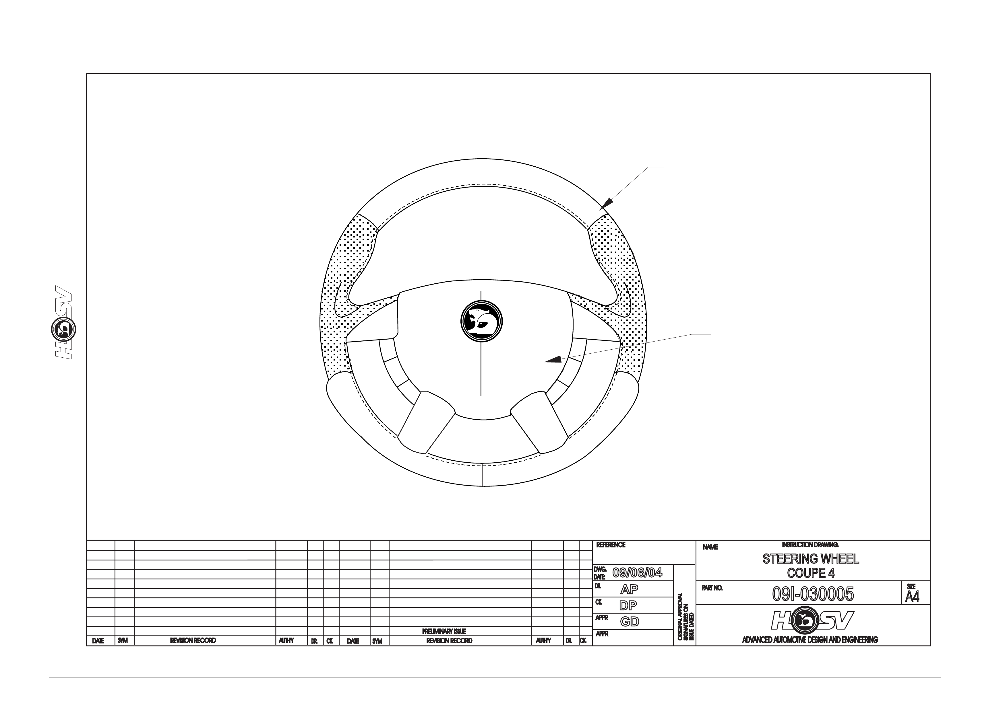
2 Steering wheel
The steering wheel assembly fitted to all HSV Coupe 4 models incorp orates an HSV design central h orn pad complete
with HSV logo, refer to drawing on 09I-030005.
The central horn pad also incorporates the driver’s side air bag.
All other components, fixtures and fasteners are identical to standard Holden parts and, therefore, any service operations
on the assembly should be carr ied out in accordance with the relevant Holden Service Information Su pplement, refer to
Section 9A Steering, of the Holden VY & V2 II Series Service Information.
Wheels, Tyres And Steering Wheel Page H-4
Page H-4
DATE
ISSUE DATED
AUTH'Y
CK.
SYM
AUTH'Y
REVISION RECORD
DATE
SYM
SIGNATURES ON
ORIGINAL APPROVAL
DR.
ADVANCED AUTOMOTIVE DESIGN AND ENGINEERING
09I-030005
INSTRUCTION DRAWING.
A4
SIZE
STEERING WHEEL
COUPE 4
REVISION RECORD
PRELIMINARY ISSUE
CK.
NAME
PART NO.
CK.
REFERENCE
DWG.
DR.
DATE:
APPR
APPR
DR.
09/06/04
AP
DP
GD
STEERING WHEEL
92210150
AIR BAG
92117622

Wheels, Tyres And Steering Wheel Page H-5
Page H-5
3 Wheels And Tyres
3.1 General Description
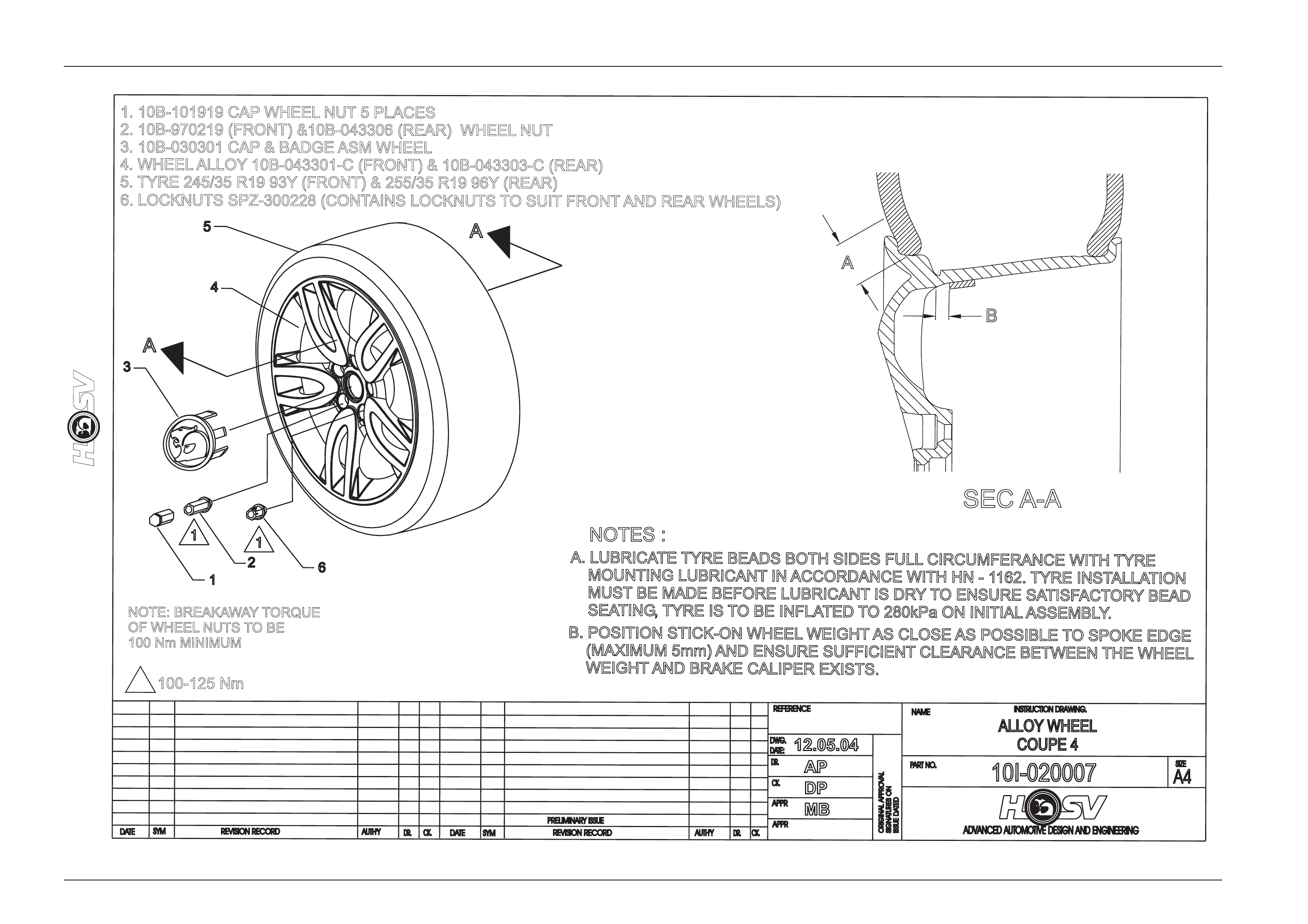
HSV Coupe 4 models are fitted with alloy wheels developed specifically for HSV application. HSV Coup e 4 has 9 inch
rear wheels and 8 inch front, therefore t yre rotation (front to rear) cannot be performe d on this model.
NOTE.
Specific wheel nuts are used to attach ‘T’ design
wheels to the vehicle. T hese nuts are fitted with a
plastic dress cap which must be removed prior to
undoing the wheel nuts.
HSV Coupe 4 wheels do not have steel insert,
and, therefore, require wheel nuts with a
flanged seat as per the VT, VT2 and VX wheel
nuts, part No. 10B-970304. Do not use VS
wheel nuts on HSV Coupe 4 wheels.

Wheels, Tyres And Steering Wheel Page H-6
Page H-6
3.2 Service Operations
Alloy wheels fitted to all HSV vehicles are to be serviced in accord ance with the procedures detailed in the relevant
Holden Service Information, refer to Section 10 Wheels and Tyres in the Holden VY & V2 II Series Service Information.
In addition , particular care shoul d be taken with the surface finish of alloy wheels. T he manufacturer recommends that
alloy surfaces be treated the same as high – gloss painted surfaces to prevent corrosi on and general deterioration.
Coupe 4 Wheel Chart
Wheel Part Number
Model Front Rear
Coupe 4 10B-043301-C 10B-043303-C
Wheels, Tyres And Steering Wheel Page H-7
Page H-7
DATE
ISSUEDA
TED
AUTH'Y
CK.
SYM
AUTH'Y
REVISION RECORD
DATE
SYM
SIGNATURES ON
ORIGINAL APPROVAL
DR.
ADVANCED AUTOMOTIVE DESIGN AND ENGINEERING
10I-020007
INSTRUCTION DRAWING.
A4
SIZE
ALLOY WHEEL
COUPE 4
REVISION RECORD
PRELIMINARY ISSUE
CK.
NAME
PART NO.
CK.
REFERENCE
DWG.
DR.
DATE:
APPR
APPR
DR.
12.05.04
AP
DP
MB
NOTE: BREAKAWAYTORQUE
OF WHEEL NUTS TOBE
100 Nm MINIMUM
100-125 Nm
1
1. 10B-101919 CAP WHEEL NUT 5 PLACES
2. 10B-970219 (FRONT) &10B-043306 (REAR) WHEEL NUT
3. 10B-030301 CAP & BADGE ASM WHEEL
4. WHEEL ALLOY 10B-043301-C (FRONT) & 10B-043303-C (REAR)
5. TYRE 245/35 R19 93Y (FRONT) & 255/35 R19 96Y (REAR)
6. LOCKNUTS SPZ-300228 (CONTAINS LOCKNUTS TO SUIT FRONT AND REAR WHEELS)
A
A
1
1
16
3
4
5
2
A.L
UBRICATE TYREBEADSBOTH SIDESFULLCIRCUMFERANCEWITH TYRE
MOUNTINGLUBRICANTIN ACCORDANCEWITH HN-1
162.TYREINSTALLATION
MUSTBEMADEBEFORELUBRICANTIS DRYTOENSURESATISFACTORYBEAD
SEATING,TYREIS TOBEINFLATEDTO280kPa ONINITIALASSEMBLY
.
B.P
OSITIONSTICK-ONWHEELWEIGHTASCLOSEASPOSSIBLETOSPOKEEDGE
(MAXIMUM5mm)ANDENSURESUFFICIENTCLEARANCEBETWEENTHEWHEEL
WEIGHTANDBRAKECALIPEREXISTS.
SEC A-A
NOTES :
A
B
Wheels, Tyres And Steering Wheel Page H-8
Page H-8
DATE
ISSUEDA
TED
AUTH'Y
CK.
SYM
AUTH'Y
REVISION RECORD
DATE
SYM
SIGNATURES ON
ORIGINAL APPROVAL
DR.
ADVANCED AUTOMOTIVE DESIGN AND ENGINEERING
10I-020009
INSTRUCTION DRAWING.
A4
SIZE
ALLOY WHEEL (TEMP SPARE)
COUPE 4
REVISION RECORD
PRELIMINARY ISSUE
CK.
NAME
PART NO.
CK.
REFERENCE
DWG.
DR.
DATE:
APPR
APPR
DR.
12.10.04
AP
DP
MB
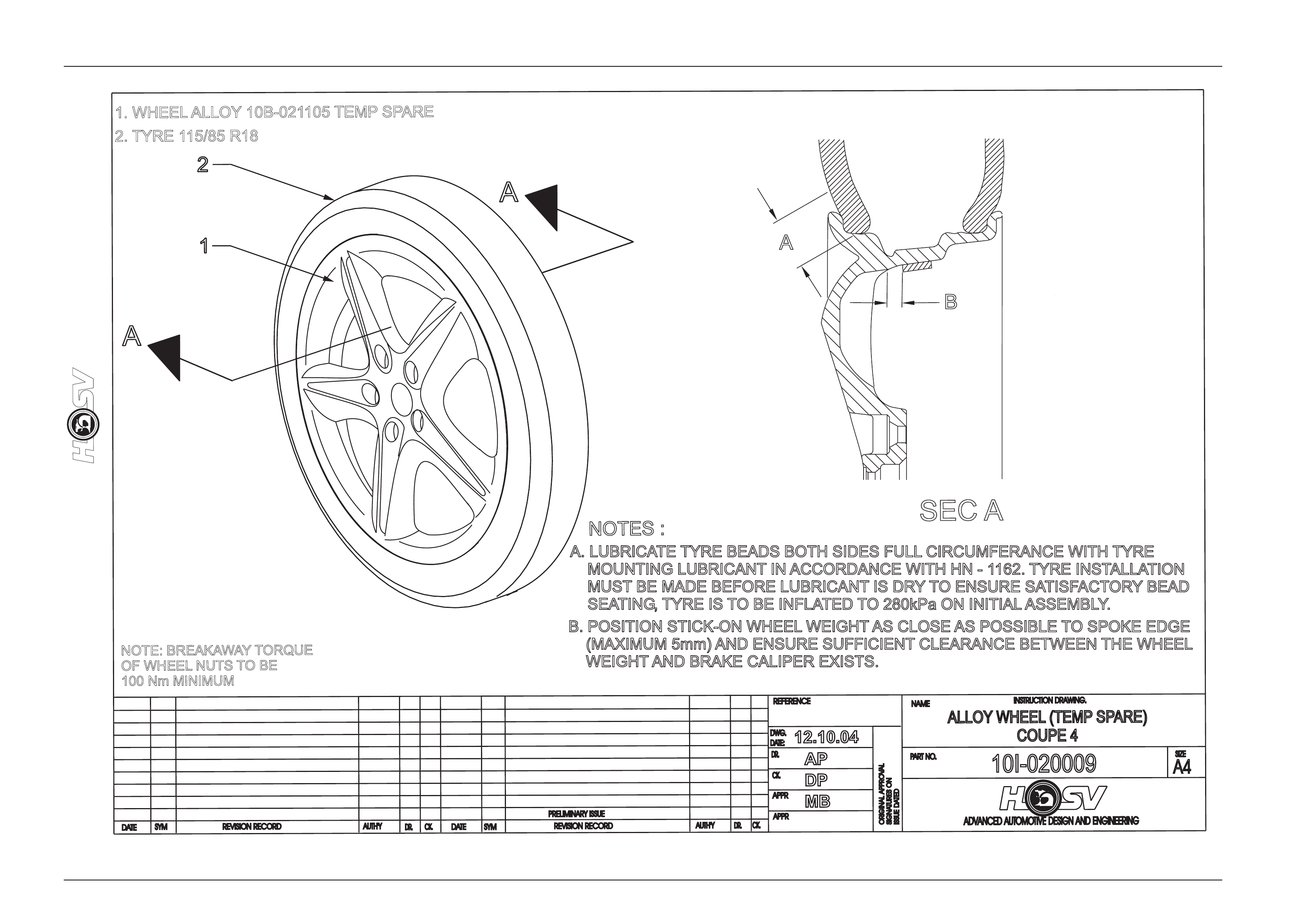
NOTE: BREAKAWAYTORQUE
OF WHEEL NUTS TOBE
100 Nm MINIMUM
1. WHEEL ALLOY 10B-021105 TEMP SPARE
2. TYRE 115/85 R18
A
A
2
1
A. LUBRICATE TYRE BEADS BOTH SIDES FULL CIRCUMFERANCE WITH TYRE
MOUNTING LUBRICANT IN ACCORDANCE WITH HN - 1162. TYRE INSTALLATION
MUST BE MADE BEFORE LUBRICANT IS DRYTO ENSURE SATISFACTORYBEAD
SEATING,TYRE IS TO BE INFLATED TO 280kPa ON INITIAL ASSEMBLY
.
B. POSITION STICK-ON WHEEL WEIGHT AS CLOSE AS POSSIBLE TO SPOKE EDGE
(MAXIMUM 5mm) AND ENSURE SUFFICIENT CLEARANCE BETWEEN THE WHEEL
WEIGHT AND BRAKE CALIPER EXISTS.
SECA
NOTES:
A
B