
Electrical And Instruments Page I-1
Page I-1
Section I
Electrical And Instruments
ATTENTION:
HSV vehicles are equipped with a Supplemental Restraint System (SRS). An SRS consists of seat belt pre-
tensioners (fitted to all front seats), a dri ver’s-side air bag , a passenger’s-sid e air bag and right and left h and
side air bags. Refer to CAUTIONS, Section 12M, in Volume 12 of the Holden V2 Series Coupe Service Manual
before performing any service operation on or around SRS components, the steering mechanism or wiring.
Failure to follow the CAUTIONS could result in personal injury or unnecessary SRS system repa irs.
1 General Information ...............................................................................................................................2
2 Purpose...................................................................................................................................................3
3 Instrumentation ......................................................................................................................................4
3.1 General ................................................................................................................................................................... 4
3.2 Service Operations................................................................................................................................................ 5
4 Electrical Facilities.................................................................................................................................6
5 Parking Sensors.....................................................................................................................................7
6 L.E.D. Interior Affect Lighting ...............................................................................................................8
7 HSV Embedded Security System........................................................................................................10
7.1 General ................................................................................................................................................................. 10
7.2 Linking the ESS to a new BCM at the Retailer – BCM In Warranty..................................................................11
7.3 Linking the ESS to a new BCM at the Retailer – BCM out of Warranty........................................................... 12
7.4 Key Programming Mode...................................................................................................................................... 13
Programming Extra Keys to the Vehicle............................................................................................................ 13
Programming All New Key.................................................................................................................................. 13
7.5 Link Enable Procedure........................................................................................................................................ 14
7.6 Service Operations.............................................................................................................................................. 15
8 Electro-Chromatic Mirrors...................................................................................................................19
8.1 General ................................................................................................................................................................. 19
9 HSV High Intensity Discharge (HID) Xenon Lights...........................................................................20
9.1 General ................................................................................................................................................................. 20
9.2 Specific................................................................................................................................................................. 21
10 HSV Rear Spoiler..................................................................................................................................25
10.1 Service Operations.............................................................................................................................................. 25
10.2 Centre High Mounted Stop Lamp Installa tion ................................................................................................... 26

Electrical And Instruments Page I-2
Page I-2
1 General Information
The electrical system as fitted to HSV Coupe 4 models carriesover from Holden V2 Coupe series models.
Refer to the relevant information in Section 12 of the Holden Coupe 2 series Service Information
Electrical And Instruments Page I-3
Page I-3
2 Purpose
The purpose of this supplement is to provide information on the HSV electrical and instrument accessories fitted to the
HSV Coupe 4 model. The information is designed to supplement that given in the Ho lden V2 Coupe Service Man uals
and details are given where differences occur between the HSV models, and standard Holden models. A series of
instruction drawings describe the design changes and indicate specific par t numbers, fitting instructions and relevant
notes for vehicle servicing.
NOTE:
If specific technical data on a HSV model is not
contained in this supplement, obtain data for that
model from the Holde n V2 Coupe Servic e Manual
Supplement. References are made throughout
this section to Holden Service Manuals, to assist
in providing information for specific service
operations.
When hoisting (or jacking) HSV models,
ensure that the lifting h ead o f th e hoist lifts on
the chassis before the arm of the hoist
contacts the side-skirt

Electrical And Instruments Page I-4
Page I-4
3 Instrumentation
3.1 General
A special Instrument Cluster designed by HSV is fitted to all HSV Co upe 4 models. The cluster includes a HSV
speedometer with an oper ating range extending to 260 km/h. The cluster incorporates a white & black f ace, red ne edles,
3 MFD displays and warning lights an d, when illuminated, green numerals and l etters.

Electrical And Instruments Page I-5
Page I-5
3.2 Service Operations
The HSV Coupe 4 instrument cluster and the standard Holden Co upe cluster use the same mounting fixtures and
fasteners. Remove, service and refit the HSV instrument cluster in accordance with the procedures detailed in the
Holden Coupe V2 Service Manual.

Electrical And Instruments Page I-6
Page I-6
4 Electrical Facilities
The various special HSV options fitted to the Coupe vehicles often require that special or additional electric harness es be
installed. Some of these HSV harnesses are fitted during vehicle build-up at the Holden factory and other smaller
harnesses (often called ‘a patch harness’) are fitted at the HSV facility when the electrical option is being installed.
A summary of these electrical harnesses is included to facilitate service, re pair and retro-fitment of the HSV options.
PART No Description
12L-020601 ESS (Embedded Security System)
92118525 HSV L1/L2/L3 Sedan/L3 C ou pe Main Wiring Harness (with out Telematics)
92118518 HSV L1/L2/L3 Sedan/L3 C oupe Main Wiring Harness (with Telematics)


Electrical And Instruments Page I-8
Page I-8
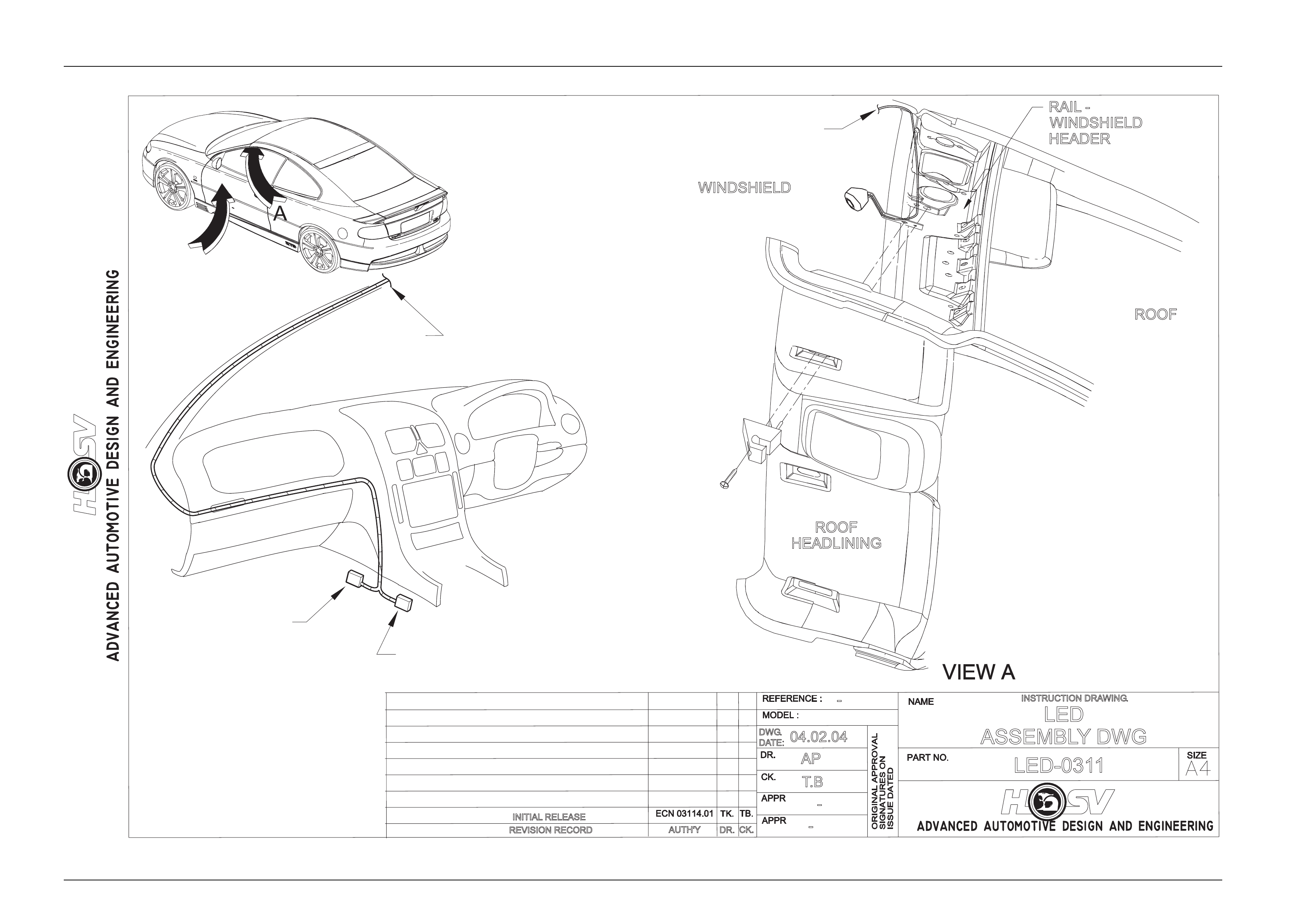
6 L.E.D. Interior Affect Lighting
All HSV Coupe 4 models are fitted with L.E.D. Interior Affect Lighting.
The L.E.D. is housed in a small plastic bezel that is heat staked to a bracket. The bracket is mounted between the left
hand sun-visor hook an d the sheet metal of the vehicle.
The L.E.D. should turn on when the vehicle is unlocked using the remote key FOB and extinguish 10 seconds after the
car is locked.
The L.E.D. is an effect light that is supposed to give a dim wash of light across the centre console and left side of the
dashboard. It is NOT a reading or courtesy lamp.
The L.E.D. is not a serviceable item and should be replace d if damaged. An electrical representation is given under the
drawing labelled LED-0311
Electrical And Instruments Page I-9
Page I-9
REVISION RECORD
INSTRUCTION DRAWING
.
-
AUTH'Y CK.
DR.
-
AP
T
.B
04.02.04
DWG
.
DATE:
LED-0311
-
LED
ASSEMBLYDWG
INITIAL RELEASE
ROOF
HEADLINING
WINDSHIELD
RAIL -
WINDSHIELD
HEADER
ROOF
ACCESORY
CONNECTOR
TO L.E.D.
VIEW B
COUPE III
TO “A” PILLAR
(L.H.S.)
B
CONNECTS TO TELEPHONE
ACCESORYCONNECTOR

Electrical And Instruments Page I-10
Page I-10
7 HSV Embedded Security System
7.1 General
The new HSV Embedded Security System (ESS) is fitted as standard equipment to all HSV VTII, WH, VYII and WK
model Vehicles. The ESS is a microprocessor-controlled immobiliser, which automatically interrupts essential electrical
circuits when in “armed mode”. The ESS s tores the BCM’s security code and when the car is started it reads this code
from the SCI bus. If this code is different from the stored one the ESS ent ers armed mode and prevents the vehic le from
starting.

Electrical And Instruments Page I-11
Page I-11
7.2 Linking the ESS to a new BCM at the
Retailer – BCM In Warranty
If the BCM requires replacement within the BCM warranty period, the Retailer shall be supp lied with a replacement B CM
programmed with the same BCM securit y code as the ori ginal BCM. In this case, the replacement BCM and new keys
are simply fitted to the vehicle. No ESS specific requireme nts are needed.

Electrical And Instruments Page I-12
Page I-12
7.3 Linking the ESS to a new BCM at the
Retailer – BCM out of Warranty
When a BCM requires replacement outside the BCM warranty period the Retailer shall need to obtain a replacement
BCM and keys from Holden’s Service Parts Operation (HSPO). The replacement BCM and Keys will not contain the
same BCM Security Code as the original BCM.
When a new BCM with different BCM security code is fitted to the vehicle, the Retailer will have to do the following:
• Program a new key to the BCM.
• Link the BCM and PCM.
TECH 2 must be connected to the vehicle diagnostic connector whilst the key is being pr ogrammed and/or ESS is being
linked to the vehicle. The Link Enable Procedure is require d to be performed twice to allow an all new key to be
programmed and also allow the ESS learn to learn the BCM security code. The procedure for programming a new key to
a new BCM and linking the ESS to the vehicle is as follows:
1 Fit new BCM to the vehicle.
2 Ensure all doors, boot and bo nnet are closed, all doors are unlocked, dome lamp is in the ‘doors’ position and the
radio, headlight and wash-wipe switches are off.
3 Place new key into the ignition barrel.
4 Turn ignition on. Verify ESS beeps 5 times.
5 For VT.II / VX Vehicles TECH2 must be operating in the “Normal Mode” submenu of the Body Control Module sub-
menu.
For VYII / WK Vehicles TECH2 must be operating in the Bod y Control Mod ule sub-menu only.
6 Select Key Programming function – “All New Key” - from the security sub-menu in the body menu of the TECH2.
Enter BCM security code as requested by TECH2. Complete key programming as requested by TECH2.
7 Turn ignition off and wait for 2 seconds. Turn ignition on.
8 Verify ESS beeps 5 times. (At this stage the ESS is in “armed mode”).
9 For VT.II / VX Vehicles TECH2 must be operating in the “Normal Mode” submenu of the Body Control Module sub-
menu.
For VYII / WK Vehicles TECH2 must be operating in the Bod y Control Mod ule sub-menu only.
10 Perform the Link Enable Procedure (see Section 1.5). Wait 1 second between each lock unlock to ensure the door
lock actuators function correctly during this procedure.
11 Verify that the ESS beeps twice. TECH2 reports ignition is at 12Vdc.
12 Link the PCM to the BCM using TECH2. ESS beeps twice (ESS has now learned the BCM securit y code).
13 Turn ignition off. Wait until TECH2 programming is complete.
14 Turn ignition on.
15 Turn ignition off. Wait 2 seconds.
16 Turn ignition on.
17 Verify ESS beeps once. The ESS is now operating in “normal mode”.
18 Crank engine. Verify vehicle s t arts as normal.

Electrical And Instruments Page I-13
Page I-13
7.4 Key Programming Mode
Once the ESS has been placed into key programming mode the ESS will behave as if in “sleep mode” for one ignition
cycle only. This allo ws for the one ignition cycle that is required to program a new key to a new or existing BCM. T he
ESS will enter “normal mode” for the next ignition cycle. If the BCM is a new BCM in the vehicle with a new security
code, the ESS will then enter “armed mode” as expected.
Programming Extra Keys to the Vehicle
Programming more keys for the vehicle can be achieved using TECH2 once the ESS has been re-linked to the vehicle
as described as follo ws:
1. Ensure all doors, boot and bonnet are closed, all doors are unlocked, dome lamp is in the ‘doors’ position and the
radio, headlight and wash-wipe switches are off.
2. Place new key into the ignition barrel.
3. Turn ignition on. Verify ESS beeps 5 times.
4. F or VT.II / VX Vehicles TECH2 must be operating in the “ Normal Mode” submenu of the Body Control Modul e sub-
menu.
For VYII / WK Vehicles TECH2 must be operating in the Bod y Control Mod ule sub-menu only.
5. Perform the Link Enable Procedur e (see Section 1.5). Wait 1 second between each lock unlock to ensure the door
lock actuators function correctly during this procedure.
6. Verify that the ESS bee ps twice. TECH2 reports ignition is at 12Vdc. The ESS has now entered “Key Pr ogramming
mode”.
7. Select Key Programming function – “Extra Key” - from the security sub-menu in the body menu of the TECH2.
When TECH2 requests ignition to be cycled with button on the existing key. Verify the ESS beeps once and the
Theft Deterrent LED stops flas hing. Complete key programming as re quested by TECH2.
8. Turn ignition off and wait for 2 seconds.
9. Turn ignition on. Verify ESS beeps once. The ESS is now operating in “normal mode”.
10. Crank engine. Verify vehicle s t arts as normal.
Programming All New Key
Programming an All New Key for the vehicle can be achieved b y performing the following procedure:
1. Ensure all doors, boot and bonnet are closed, all doors are unlocked, dome lamp is in the ‘doors’ position and the
radio, headlight and wash-wipe switches are off.
2. Place new key into the ignition barrel.
3. Turn ignition on. Verify ESS beeps 5 times.
4. F or VT.II / VX Vehicles TECH2 must be operating in the “ Normal Mode” submenu of the Body Control Modul e sub-
menu.
For VYII / WK Vehicles TECH2 must be operating in the Body Control Mod ule su b-menu.
5. Perform the Link Enable Procedur e (see Section 1.5). Wait 1 second between each lock unlock to ensure the door
lock actuators function correctly during this procedure.
6. Verify that the ESS bee ps twice. TECH2 reports ignition is at 12Vdc. The ESS has now entered “Key Pr ogramming
mode”.
7. Select Key Programming function – “All New Key” - from the security sub-menu in the body menu of the TECH2.
Enter BCM security code as requested by TECH2. Complete key programming as requested by TECH2.
8. Turn ignition off and wait for 2 seconds.
9. Turn ignition on. Verify ESS beeps once and Theft Deterrent LED is off. The ESS is now operating in “normal mode”.
10. Crank engine. Verify vehicle s t arts as normal.

Electrical And Instruments Page I-14
Page I-14
7.5 Link Enable Procedure
Each ESS has it’s own unique Link Enable C ode (LEC), programmed into each ESS by HSV. This code corres ponds to
a unique sequence of 10 vehicle body functions comprising of the following actions:
1 Drivers door. Open then Close
2 Drivers door Snib. Lock then Unlock
3 Wash-Wipe. On then off.
Approximately 60,000 link enable codes ar e available.
For the Link Enable Procedure contact Australian Arrow Pty Ltd Customer Service quoting ESS PIN and Vehicle
Identification / Tag Number.
Telephone: (03) 9785 0792
Facsimile: (03) 9775 0954

Electrical And Instruments Page I-15
Page I-15
7.6 Service Operations
In the event of a suspected ESS failure the following check sheet must be followed.
Electrical And Instruments Page I-16
Page I-16
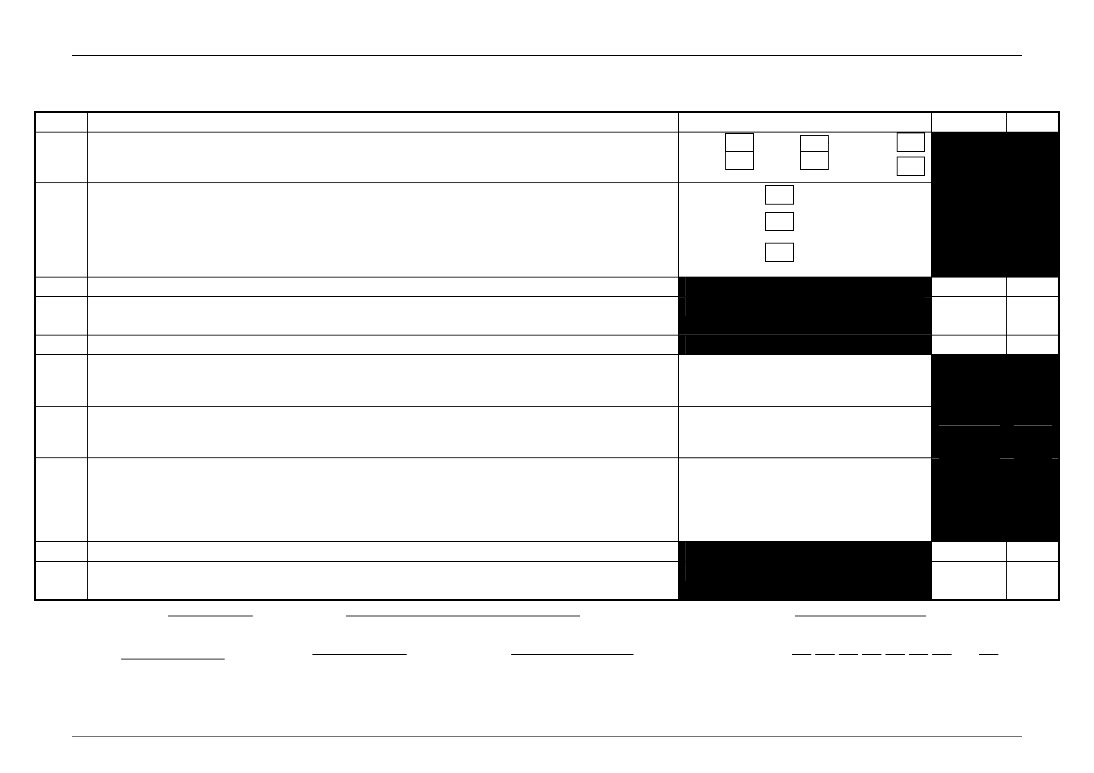
HSV – EMBEDDED SECURITY SYSTEM (ESS) CHECK SHEET (VT.II / WH / VY / WK / Coupe III / Coupe 4).
In the event of a suspected ESS failure, fill in the follow ing check sheet.
STEP ACTION MEASURED VALUE YES NO
What type of vehicle has the suspected ESS failure? VT.II : VY : CoupeIII
WH : WK : Coupe 4
1 Turn ignition to ON position and listen for the numb er of be eps. Zero beeps:
One beep:
Five beeps: Other:______
2 With the ignition in the ON position, is the Theft Deterrent Led flashing?
3 Turn Ignition switch to the Start position.
Does the vehicle start?
4 Has there been a BCM replacement?
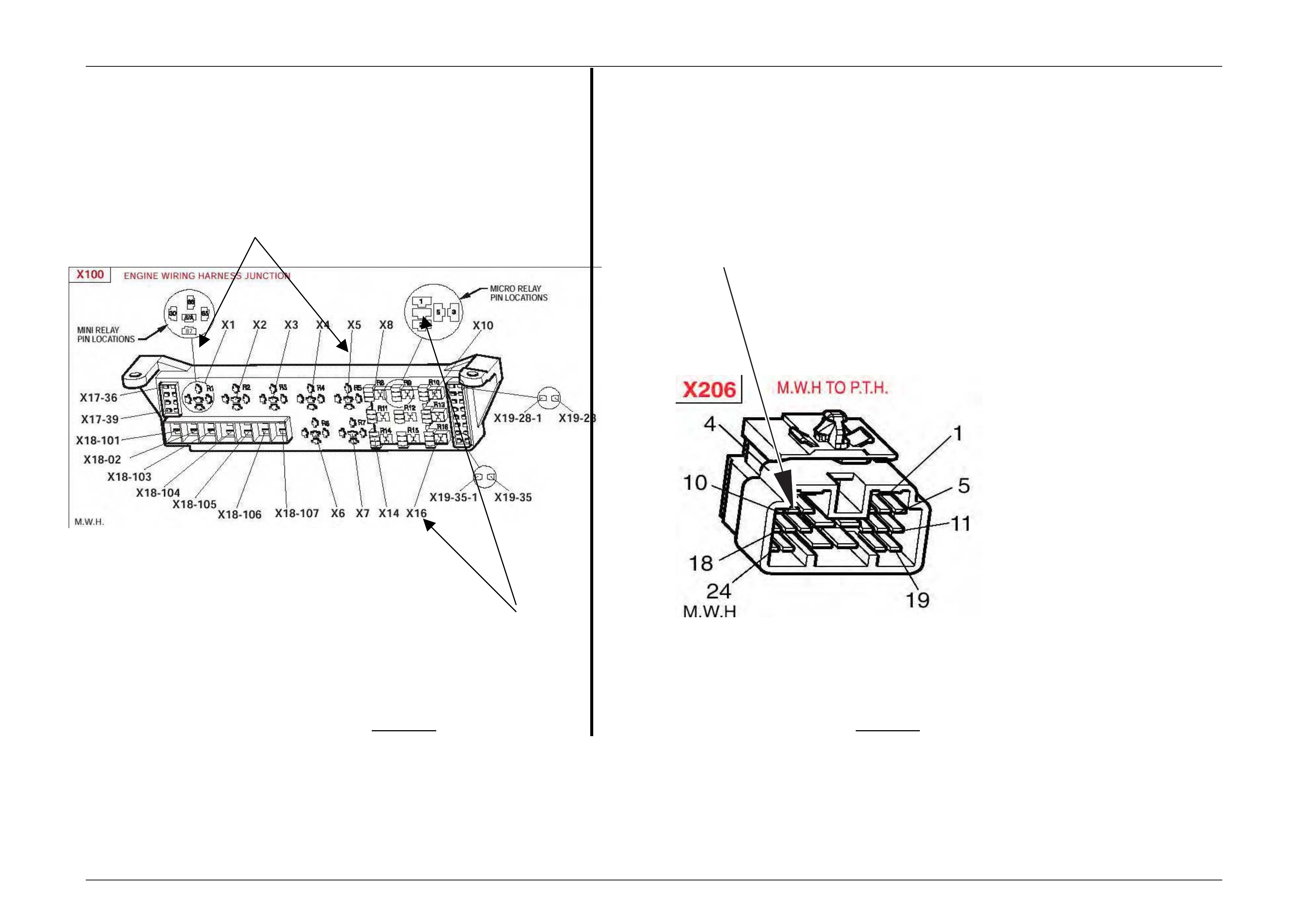
5 Remove the EFI relay and back probe terminal 8 5 (as per figure 1 for VT.II / WH Vehicles or as per figure 3 for
VY / WK / Coupe 4 Vehicles), with reference to Ground.
With the Ignition switch to ON, measure DC voltage.
_____________ volts DC.
6 Remove Fuel Pump rela y and back probe terminal 1 (as per figure 1 for VT.II / WH Vehicles) or terminal.2 (as
per figure 3 for VY / WK / Coupe 4 Vehicles), to measure continuity with ref. to Ground.
Turn the ignition to ON, measure resistance.
_____________ Ohms.
7 For VY / WK Vehicles Disconnect Engine C onnector (X206 located above passenger kick panel) and back
probe pin 9 (as per figure 4) with reference to ground.
For VT.II / WH / Coupe 4 Vehicles Disconnect Engine Connector (YE112) and back probe pin (as per figure 2),
with reference to Ground.
Turn the ignition to ON, measure DC voltage.
_____________ volts DC
8 Is communications with Tech 2 active?
9 With TDL flashing, operate “Unlock” button on the Remote Control.
Does the TDL stop flashing?
Dealer Code: ISOVIN: Vehicle Build Date:
Km’s: ESS Pin No: BCM Part No: BCM Barcode No: .
This check sheet mu st signed by the Service Man ager. ____________________________ Date: ____________
Fax the completed cop y to Australian Arrow Customer Service. Facsimile: (03) 9775 0954.

Electrical And Instruments Page I-17
Page I-17
STEP ACTION VALUE YES NO
1 • Turn ignition to ON position.
• Is one (1) beep audible?
• Go to Step 2 • Go to Step 3.
2 • Turn Ignition switch to the Start position.
• Does the vehicle start?
• System O.K, return
vehicle to customer. • Go to Step 11.
3 • Are five (5) beeps audible? • Go to Step 13. • Go to Step 8.
4 • Turn Ignition switch to the Start position.
• Does the vehicle start?
• Go to Step 5. • Go to Step 6.
5 • Fill in the ESS check sheet and Co ntact Australian Arrow Customer Service.
6 • Has there been a BCM replacement? • Go to Step 5. • Go to Step 14.
7 • Perform Serial Data Commun i cations diagnostic as per Holden Service
Manual, then go to Step 5.
8 • Zero beeps were audible? • Go to Step 9. • Record number of beeps,
then go to Step 5.
9 • Turn Ignition switch to the Start position.
• Does the vehicle start?
• Go to Step 5. • Go to Step 10.
10 • Remove the EFI relay and back probe terminal 85 (as per figure.1 for VT.II / WH
vehicle), or (as per figure.3 for VY/WK/CoupeIII/Coupe 4 vehicle), with reference
to Ground.
• With the Ignition switch to ON, Is the value as specified?
• 12 volts DC. • Go to Step 5. • Refer to Service Manual and
check Ignition system.
11 • Remove Fuel Pump rela y and back probe terminal.1 (as per figure.1 for VT.II /
WH vehicle), or (as per figure.3 terminal.2 for VY/WK/CoupeIII/Coupe 4 vehicle),
to check continuity with reference to Ground.
• Turn the ignition to ON. Is the value as specified?
• Less than one
(1) Ohm. • Go to Step 12. • Go to Step 5.
12 • For VT.II / WH vehicle, Disconnect Engine Connector (YE112) and back probe pin
(as per figure 2), with reference to Ground.
• For VY/WK/CoupeIII/Coupe 4 vehicle, Disconnect Engine Connector (X206
located above passenger kick panel), and back probe pin.9 (as per figure.4), with
reference to ground.
• Turn the ignition to ON. Is the value as specified?
• 12 volts DC • Go to Step 5. • Go to Step 5.
13 • Is the Theft Deterrent Led flashing? • Go to Step 4. • Go to Step 5.
14 • Is communications with Tech 2 active? • Go to Step 15. • Go to Step 7.
15 • With TDL flashing, operate “Unlock” button on the Remote Key.
• Does the TDL stop flashing?
• Go to Step 5. • Refer to Theft Deterrent
System diagnostics in Ho lden
Service Manual.
Electrical And Instruments Page I-18
Page I-18
Engine bay Relay Box Engine harness connector X206
EFI relay (X5)
Refer to diagnostic Step 10
Back probe terminal 85
Refer to diagnostic step 12 (Pin 9)
Fuel pump relay (X16)
Refer to diagnostic STEP 11
Back probe terminal 2
FIGURE 3 FIGURE 4
Australian Arrow Pty Ltd.
Customer Service
Telephone: (03) 9785 0792
Facsimile:(03)9775 09 54

Electrical And Instruments Page I-19
Page I-19
8 Electro-Chromatic Mirrors
8.1 General
Electro-chromatic mirrors are standard fitment in Coupe 4 vehicles. The mirror features an electronically controlled mirror
cell which changes colour in r espo nse to an applied electric al volta ge. This allows automatic darkening of the mirror
during night driving when the headlamps of a following veh icle shi ne on an integrated light sensor. This function only
operates when the integral sensor detects low ambi ent (i.e. at night time). The mirror operates automatically, however,
an AUTO/MANUAL switch provides the driver with the option for the mirror to be darken ed during low ambient light
conditions regardless of prese nce or absence of following headlamps. When reverse gear is selected, the mirror
automatically lightens. Remove, service and refit the HSV Electro-Chromatic Mirror in acc orda nce with the procedures
detailed in the Holden C oupe V2 Service Manual.

Electrical And Instruments Page I-20
Page I-20
9 HSV High Intensity Discharge
(HID) Xenon Lights
9.1 General
HSV Coupe 4 vehicles are fitted with HID Driving Lights. These HID lights are located i n the Fog lamp position on the
front fascia.
Note: HID Lights operate at quite high voltage levels, so all care must be taken when removing front fascia for service or
repair. Please refer to Service/Owners manual and take note of warnings in engine bay.
HID lights are designed only to operat e when high beam is activated. i.e. when indicator stalk is pulled toward (flashed)
or pushed back to operate high beams. They are not a fo g light and should not be use d in any other manner, other th an
described above.
HID Lights offer a brilliant white light that will illuminate above and beyond a standard ‘High Beam’ s ystem. All care must
be taken when using or adjusting these lights, as they can dazzle the operator.
The HID lights, ballasts and looms are not serviceable items and shoul d be replaced if damaged.

Electrical And Instruments Page I-21
Page I-21
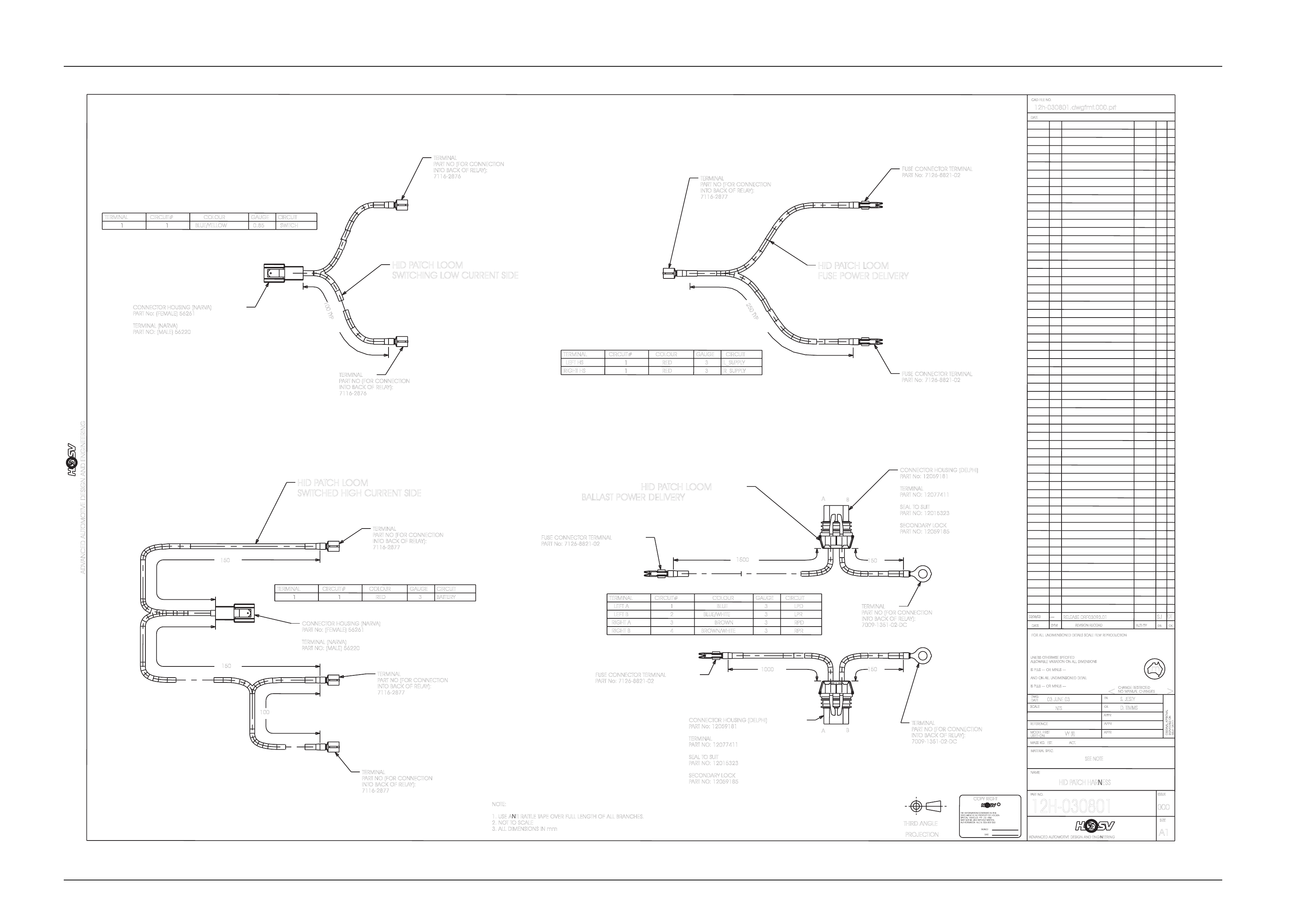
9.2 Specific
HID Lights use a separate patch har ness that taps into the high be am activation circuit, these looms also prov ide power
to the HID ballasts. The loom has drawing number – Coupe 4 / Senator: 12H-030801. Fuses for the HID lights are
located next to fuse box in engine bay and are labeled Left Hand LH HID and Right Hand RH HID.
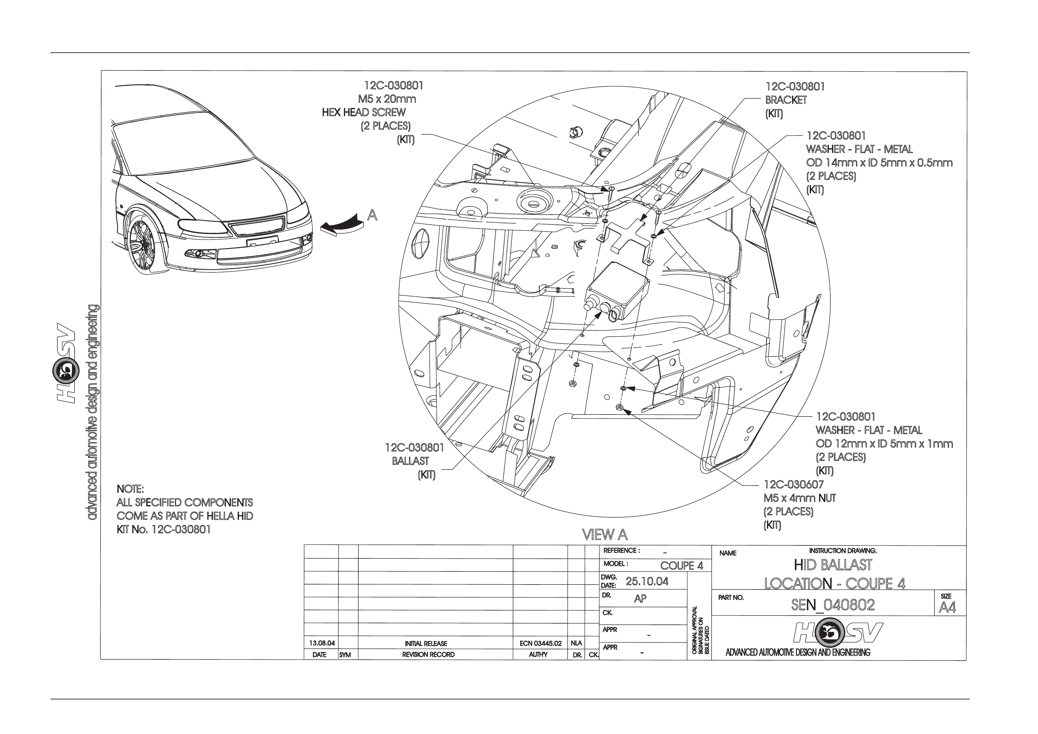
Ballasts are located under the headlights, attached to the sheet metal of vehicle, as per instruction drawing Senator:
SEN_030802. T hese ballasts power up the globes.
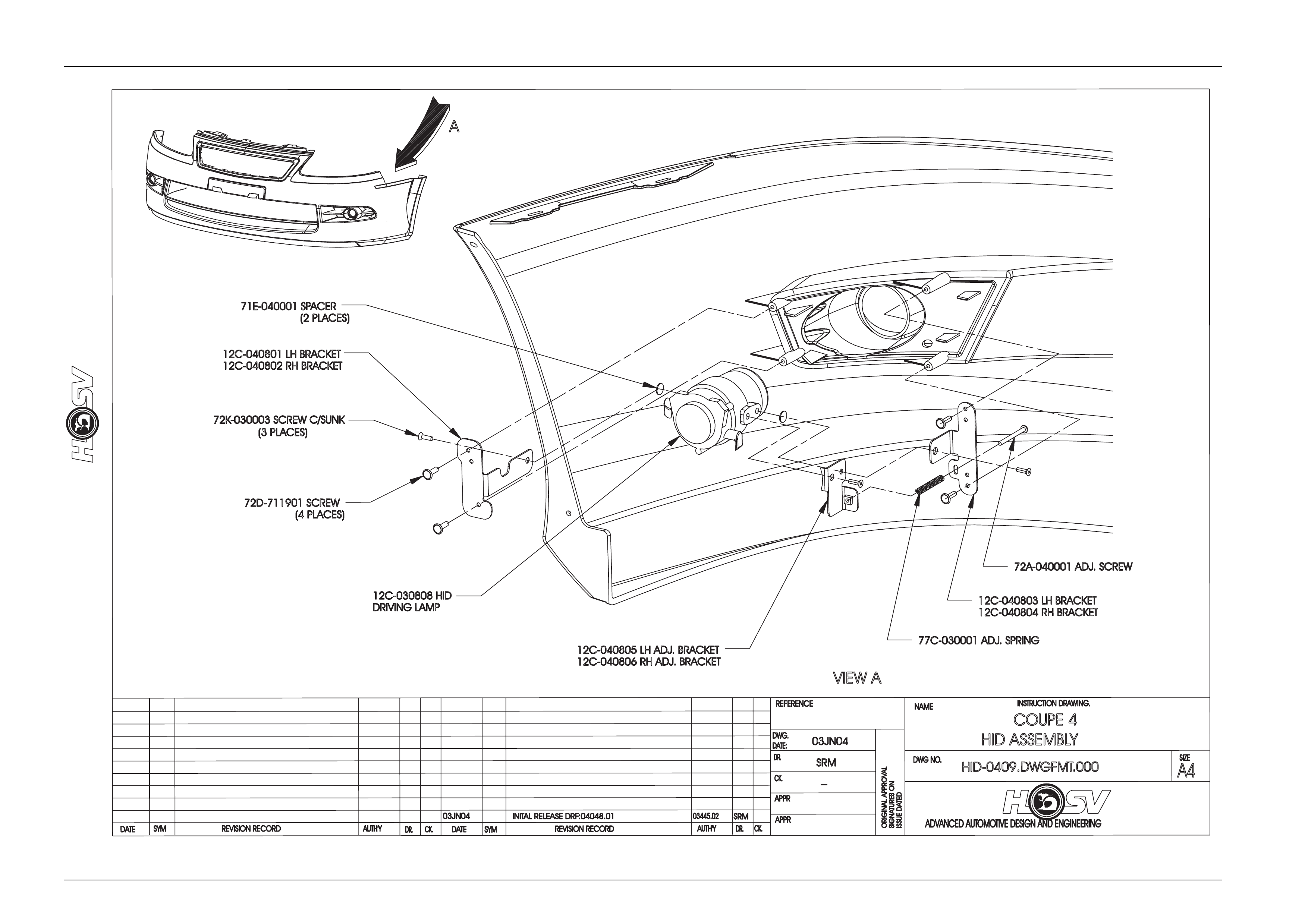
HID Globes are located in front fascia below headlights. They consist of a HID Bulb, Lens, Brackets and adjusting
equipment, all containe d within the Fog light position. Instruction drawing number – Coupe 4 1A2F-0400 12
Electrical And Instruments Page I-22
Page I-22
RELEASED
RF03093.01
UNLESSO
THERWISES
PECIFIED
m
AUTH'TY
A1
APPR
>
AUTHORISATIONA.C.N.006802053
DWG.
THIRDA
NGLE
SYM
S. JESTY
NOMANUALC
HANGES
SPECIALVEHICLESPTYLTDAND
12h-030801.dwgfmt.000.prt
REFERENCE
SIGNATURESO
N
12H-030801
ANDO
NA
LLU
NDIMENSIONEDD
ETAIL
MATERIALS
PEC.
CK.
03 JUNE 03
SEE NOTE
THEINFORMATIONCONTAINEDINTHIS
FORA
LLU
NDIMENSIONEDD
ETAILSS
CALEF
ILMR
EPRODUCTION
DR.
DATE
ADVANCED AUTOMOTIVE DESIGN AND ENGINEERING
NAME
C
ADVANCED AUTOMOTIVE DESIGN AND ENGINEERING
APPR
SIZE
DATE
SIGNED
CK.
03/06/03
PARTN
O.
HID PATCH HARNESS
APPR
NTS
COPYR
IGHT
USEDO
N
<
MAYNOTBEUSEDWITHOUTWRITTEN
PROJECTION
SCALE
ISSUEDATED
D. TIMMS
DATE
ISSUE
IS PLUS-
--O
RM
INUS-
--
MASSK
G.E
ST.A
CT.
CHANGER
ESTRICTED
DOCUMENTISTHEPROPERTYOFHOLDEN
DR.
ALLOWABLEV
ARIATIONO
NA
LLD
IMENSIONS
MODELF
IRST
ORIGINALAPPROVAL
000
IS PLUS-
--O
RM
INUS-
--
REVISIONR
ECORD
CAD FILE NO.
DATE
--- SJ
NOTE:
1. USE ANTI RATTLE TAPE OVER FULL LENGTH OF ALL BRANCHES.
2. NOTT
OSCALE
3. ALL DIMENSIONS IN mm
VY(
II)
DT
CONNECTOR HOUSING (NARVA)
PART No: (FEMALE) 56261
TERMINAL (NARVA)
PART NO: (MALE) 56220
CIRCUIT
CIRCUIT#
TERMINAL GAUGE
COLOUR
3BATTERY
1RED
1
TERMINAL
PART NO (FOR CONNECTION
INTOBACK OF RELAY):
7116-2877
HID PATCH LOOM
SWITCHED HIGH CURRENT SIDE
CONNECTOR HOUSING (NARVA)
PART No: (FEMALE) 56261
TERMINAL (NARVA)
PART NO: (MALE) 56220
TERMINAL
PART NO (FOR CONNECTION
INTOBACK OF RELAY):
7116-2876
TERMINAL
PART NO (FOR CONNECTION
INTOBACK OF RELAY):
7116-2876
CIRCUIT#
TERMINAL
11
CIRCUIT
GAUGE
0.85 SWITCH
BLUE/YELLOW
COLOUR
HID PATCH LOOM
SWITCHING LOW CURRENT SIDE
100TYP
250TYP
CIRCUIT#
TERMINAL
LEFT HS 1
CIRCUIT
GAUGE
3L_SUPPLY
RED
COLOUR
RIGHT HS 1RED 3R_SUPPLY
FUSE CONNECTOR TERMINAL
PART No: 7126-8821-02
FUSE CONNECTOR TERMINAL
PART No: 7126-8821-02
1500 150
1000 150
TERMINAL
LEFT A
LEFT B
1
CIRCUIT
GAUGE
3LPD
BLUE
COLOUR
2BLUE/WHITE 3LPR
CIRCUIT#
RIGHT A3BROWN 3RPD
RIGHT B4BROWN/WHITE 3RPR
FUSE CONNECTOR TERMINAL
PART No: 7126-8821-02
FUSE CONNECTOR TERMINAL
PART No: 7126-8821-02
CONNECTOR HOUSING (DELPHI)
PART No: 12059181
TERMINAL
PART NO: 12077411
SEAL TOSUIT
PART NO: 12015323
SECONDARY LOCK
PART NO: 12059185
CONNECTOR HOUSING (DELPHI)
PART No: 12059181
TERMINAL
PART NO: 12077411
SEAL TOSUIT
PART NO: 12015323
SECONDARY LOCK
PART NO: 12059185
A
A
B
B
HID PATCH LOOM
FUSE POWER DELIVERY
HID PATCH LOOM
BALLAST POWER DELIVERY
TERMINAL
PART NO (FOR CONNECTION
INTOBACK OF RELAY):
7116-2877
TERMINAL
PART NO (FOR CONNECTION
INTOBACK OF RELAY):
7116-2877
150
150
100
TERMINAL
PART NO (FOR CONNECTION
INTOBACK OF RELAY):
7009-1351-02-DC
TERMINAL
PART NO (FOR CONNECTION
INTOBACK OF RELAY):
7116-2877
TERMINAL
PART NO (FOR CONNECTION
INTOBACK OF RELAY):
7009-1351-02-DC
Electrical And Instruments Page I-23
Page I-23
advanceda
utomotived
esigna
nde
ngineering
REVISION RECORD
SYM
DATE
INSTRUCTION DRAWING.
ADVANCEDA
UTOMOTIVED
ESIGNA
NDE
NGINEERING
-
AUTH'Y CK.
DR.
-
APPR
COUPE 4
AP
25.10.04
APPR
CK.
DR.
MODEL :
DWG.
DATE:
REFERENCE :
PART NO.
SEN_040802
-
NAME
HID BALLAST
LOCATION-CO
UPE 4
A4
SIZE
ORIGINAL APPROVAL
ISSUE DATED
SIGNATURES ON
13.08.04
-
ECN 03445.02 NLA
INITIAL RELEASE
VIEW A
12C-030801
M5 x 20mm
HEX HEAD SCREW
(2 PLACES)
(KIT)
12C-030801
BALLAST
(KIT)
12C-030801
BRACKET
(KIT)
A
12C-030607
M5 x 4mm NUT
(2 PLACES)
(KIT)
12C-030801
WASHER - FLAT - METAL
OD 12mm x ID 5mm x 1mm
(2 PLACES)
(KIT)
12C-030801
WASHER - FLAT - METAL
OD 14mm x ID 5mm x 0.5mm
(2 PLACES)
(KIT)
NOTE:
ALL SPECIFIED COMPONENTS
COME ASP
ART OF HELLA HID
KIT No. 12C-030801
Electrical And Instruments Page I-24
Page I-24
ADVANCED AUTOMOTIVE DESIGN AND ENGINEERING
INSTRUCTION DRAWING.
A4
SIZE
REVISION RECORD
CK.
NAME
DWG NO.
CK.
REFERENCE
DWG.
DR.
DATE:
APPR
APPR
DR.
AUTH'Y
REVISION RECORD
AUTH'Y
SYM
DATE
DR.CK.
DATE
SYM
ORIGINAL APPROVAL
SIGNATURES ON
ISSUE DATED
03JN04
03JN04 INITAL RELEASE DRF:04048.01
SRM
COUPE 4
HID ASSEMBLY
HID-0409.DWGFMT.000
VIEW A
--
03445.02
SRM
71E-040001 SPACER
(2 PLACES)
12C-040801 LH BRACKET
12C-040802 RH BRACKET
72K-030003 SCREW C/SUNK
(3 PLACES)
72D-711901 SCREW
(4 PLACES)
12C-040805 LH ADJ. BRACKET
12C-040806 RH ADJ. BRACKET
12C-040803 LH BRACKET
12C-040804 RH BRACKET
72A-040001 ADJ. SCREW
77C-030001 ADJ. SPRING
12C-030808 HID
DRIVING LAMP
A

Electrical And Instruments Page I-25
Page I-25
10 HSV Rear Spoiler
The HSV Coupe 4 models are fitted with Rear Spoiler incorporating Centre High Mounted Stop Lamp (CHMSL).
10.1 Service Operations
To service the HSV Coupe Deck Lid Spoiler mounted stop lamp the following procedure applies:
1 Open deck lid;
2 Disconnect vehicle’s battery leads;
3 Remove the deck lid inner trim retainers a nd trim panel;
4 Disengage the Centre High Mounted Stop Lamp’s har ness connector from the deck lid har ness connector that is
mounted on the right hand side of the deck lid in ner panel.
Refer to drawing shown on page 14.
5 Remove CHMSL wires and terminals from the CHMSL connector and take note of the wire colours and locations in
the connector;
6 Remove the two lamp retaining screws;
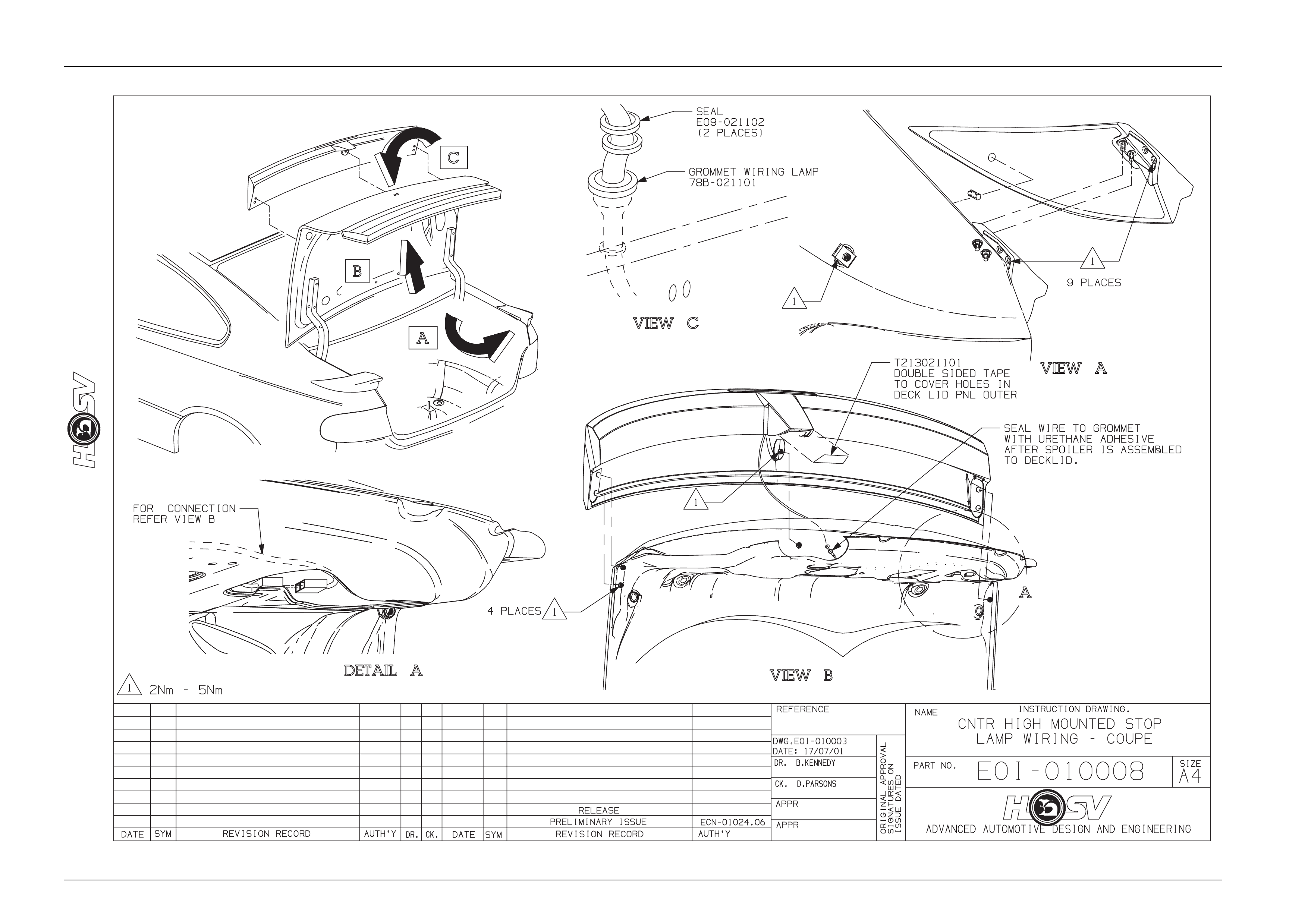
7 The lamp wiring passes through a CHMSL gasket and a grommet located in the deck lid outer panel under the
spoiler. The wire is sealed to the grommet with urethan e sealer and this seal must be broken to allo w the lamp’s
wiring to move, which will allow free pla y in the wiring so that the lamp can be pulled out of its mounting cavity in
the spoiler and thus giving access to the wiring at the rear of the lamp;
8 Cut the lamp’s wiring leaving a 50mm length of wire protruding from the spoiler, and discard the lamp and the
gasket;
9 Strip 12mm of insulation off the end of the two lamp wires now protruding from the spoiler lamp cavity and tin with
solder.

Electrical And Instruments Page I-26
Page I-26
10.2 Centre High Mounted Stop Lamp
Installation
1 Install the lamp’s gasket to the lamp with the wiring passing through its access hole;
2 Strip 12mm of insulation off the end of the replacement lamp’s wires and solder join these to the cut original lamp’s
wires protruding from the spoiler. Ensure that an excess of solder is not used, but the joint must be strong as it will
be used to pull the wires from the new lamp through the rear spoiler and deck lid outer panel us ing the original
lamp’s wires;
3 Carefully pull the wires through the sp oiler and deck lid outer panel while feeding the new lamp wiring through. Do
not use excessive force if the wiring stops or appears to snag. If this is encountered the spoiler will have to be
removed to reinstall the wiring and lamp assembly. Refer to drawings on page 16. for this information. Ensure that
the new lamp’s Gasket is located between the lamp base and the bottom of the spoiler recess, and is not kinked or
buckled, and that the wiring passes through the access hole in the gasket;
4 Install the lamp and gasket int o the spoiler recess;
5 When inserting the CHMSL into the recess ta ke care not to damage the wiring and gasket, and fasten the attachin g
screws;
6 Once installed cut the CHMSL wires to a lengt h that allows the wires to run to the connector located on the deck lid
inner panel;
7 Strip the insulation off the wires and attach the ne w terminals provid ed, install the terminals into the connector
housing using the wiring colours and locations previously noted in the removal procedure;
8 Assemble the CHMSL connector and wiring with the deck lid connector and harness assembly;
9 Reconnect the battery terminals and check the function of the lamp;
10 If the lamp does not function it is possible that the wires have been incorrectly installed in their locations in the
connector body. Refer to the wiring and colour locations noted prior to the removal procedure;
11 Seal the CHMSL wiring where it passes through the deck lid grommet with urethane sealer.
Refer to drawing E0I-010008, view B;
12 Install the deck lid inner panel trim and retainers;
13 Clean and polish all ar eas where work has been conducted.
Electrical And Instruments Page I-27
Page I-27