
Engine Mechanical – HSV – Gen IV V8 Page 6A4–1
Page 6A4–1
Section 6A4 -
Engine Mechanical – HSV – Gen IV V8
ATTENTION
Before performing any service operation or other procedure described in this Section, refer to Section 00
Warnings, Cautions and Notes for correct workshop practices with regard to safety and/or property damage.
1 General Information ...............................................................................................................................3
1.1 Engine View............................................................................................................................................................ 4
Left-hand Side........................................................................................................................................................ 4
Lower Front of Engine...........................................................................................................................................5
Intake Manifold – Upper Engine............................................................................................................................ 6
1.2 Engine Number ...................................................................................................................................................... 7
1.3 Engine Construction.............................................................................................................................................. 8
Cylinder Block........................................................................................................................................................ 8
Pistons and Connecting Rods.............................................................................................................................. 9
Camshaft and Drive ............................................................................................................................................. 10
Intake Manifold..................................................................................................................................................... 10
1.4 Engine Lubrication Sy s t em................................................................................................................................. 11
Positive Crankcase Ventilation System............................................................................................................. 11
2 Minor Service Operations....................................................................................................................12
2.1 Manifold Absolute Pressure Sensor .................................................................................................................. 12
Remove................................................................................................................................................................. 12
Reinstall................................................................................................................................................................ 12
2.2 Intake Manifold..................................................................................................................................................... 13
Remove................................................................................................................................................................. 13
Disassemble......................................................................................................................................................... 19
Clean and Inspect................................................................................................................................................ 20
Reassemble.......................................................................................................................................................... 21
Reinstall................................................................................................................................................................ 22
2.3 Engine Valley Cover ............................................................................................................................................ 24
Remove................................................................................................................................................................. 24
Clean and Inspect................................................................................................................................................ 25
Reinstall................................................................................................................................................................ 25
2.4 Valve Rocker Arm Cover..................................................................................................................................... 26
Remove................................................................................................................................................................. 26
Clean and Inspect................................................................................................................................................ 30
Reinstall................................................................................................................................................................ 30
2.5 Cylinder Head Assembly..................................................................................................................................... 32
Remove................................................................................................................................................................. 32
Disassemble......................................................................................................................................................... 34
Clean and Inspect................................................................................................................................................ 35
Valve Springs................................................................................................................................................... 37
Valves .............................................................................................................................................................. 37
Valve Guides.................................................................................................................................................... 38
Oversize Valve Stem........................................................................................................................................ 39
Valve Seats...................................................................................................................................................... 39
Reassemble.......................................................................................................................................................... 40
Reinstall................................................................................................................................................................ 42
2.6 Engine Dress Cover............................................................................................................................................. 44
Remove................................................................................................................................................................. 44
Reinstall................................................................................................................................................................ 44
Techline
Techline

Engine Mechanical – HSV – Gen IV V8 Page 6A4–2
Page 6A4–2
3 Major Service Operations....................................................................................................................45
3.1 Engine Assembly................................................................................................................................................. 45
Remove................................................................................................................................................................. 45
Disassemble......................................................................................................................................................... 52
Reassemble.......................................................................................................................................................... 53
Reinstall, Set-up and Testing.............................................................................................................................. 53
3.2 Engine Front Cover.............................................................................................................................................. 54
Remove................................................................................................................................................................. 54
Clean and Inspect................................................................................................................................................ 54
Reinstall................................................................................................................................................................ 55
3.3 Timing Chain and Sprockets............................................................................................................................... 57
Remove................................................................................................................................................................. 57
Clean and Inspect................................................................................................................................................ 58
Reinstall................................................................................................................................................................ 59
3.4 Camshaft .............................................................................................................................................................. 61
Remove................................................................................................................................................................. 61
Clean and Inspect................................................................................................................................................ 62
Reinstall................................................................................................................................................................ 63
3.5 Piston, Connecting Rod and Bearing................................................................................................................. 65
Remove................................................................................................................................................................. 65
Disassemble......................................................................................................................................................... 67
Clean and Inspect................................................................................................................................................ 68
Reassemble.......................................................................................................................................................... 74
Reinstall................................................................................................................................................................ 76
4 Specifications.......................................................................................................................................79
General ................................................................................................................................................................. 79
Camshaft .............................................................................................................................................................. 79
Cylinder Bore ....................................................................................................................................................... 79
Piston.................................................................................................................................................................... 80
Valve System........................................................................................................................................................ 81
5 Torque Wrench Specifications............................................................................................................82
Engine Mechanical – HSV – Gen IV V8 Page 6A4–3
Page 6A4–3
1 General Information
With the following exceptions, MY 2004 HSV VZ Engine Mechanical service information c arries over from MY 2003 HSV
VY II vehicles.
• Cylinder Block
• Valve Train
• Pistons and Connecting Rods
• Camshaft and Drive
• Intake Manifold
• Positive Crankcase Ventilation System
MY 2004 HSV VZ RWD veh icles are fitted with a 6.0 litre GE N IV V8 engi ne, production option LS2. T he GEN IV engine
is based on the previous GEN III LS1 engine and features many revisions, enhancements and larger displacement.
Cylinder layout is 1, 3, 5, and 7 for the left-hand bank an d 2, 4, 6 and 8 for the right-hand bank, with a firing order of 1-8-
7-2-6-5-4-3. The engine has a compression ratio of 10.9:1.
Two knock sensors are attached externally to the rear of cylinder block just above the oil pan mating surface. The
camshaft sensor is attached to the engine front cover an d a reluctor i ncorporated into the camshaft timing gear. A
Manifold Absolute Pressure Sensor is fitted to the front of the intake manifold. For further information relating to engine
management sensors fitted to the GEN IV V8 engine, refer to Section 6C4 Powertrain Manag ement – GEN IV V8.
Engine throttle control is achieved by an electronic throttle body, which is controlled through the engine management
system, refer to Section 6C4 Powertrain Management – GEN IV V8.
NOTE
Unless noted otherwise, the information
contained in this Section is appropriate for
manual and automatic transmission vehicles.
Compressed air and cleaning fluids are used
in various procedures throughout this
section. It is essential that the technician
wears the appropriate protective clothing,
gloves and eye wear to avoid personal injury.
Engine Mechanical – HSV – Gen IV V8 Page 6A4–4
Page 6A4–4
1.1 Engine View
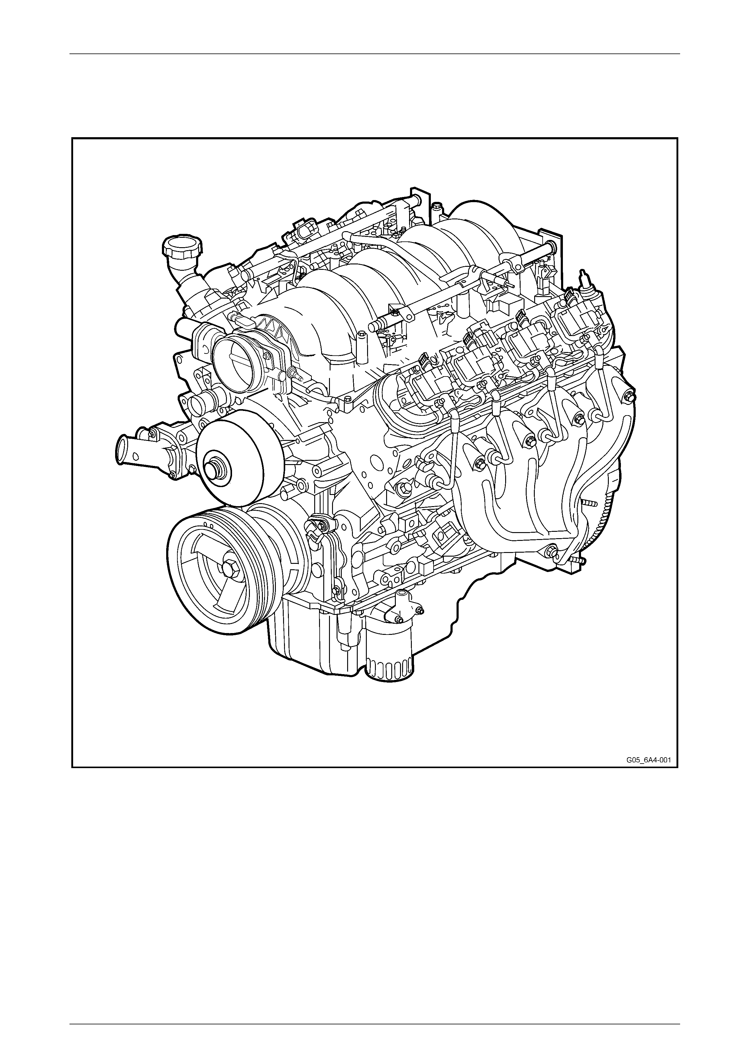
Left-hand Side
Figure 6A4 – 1
Engine Mechanical – HSV – Gen IV V8 Page 6A4–5
Page 6A4–5
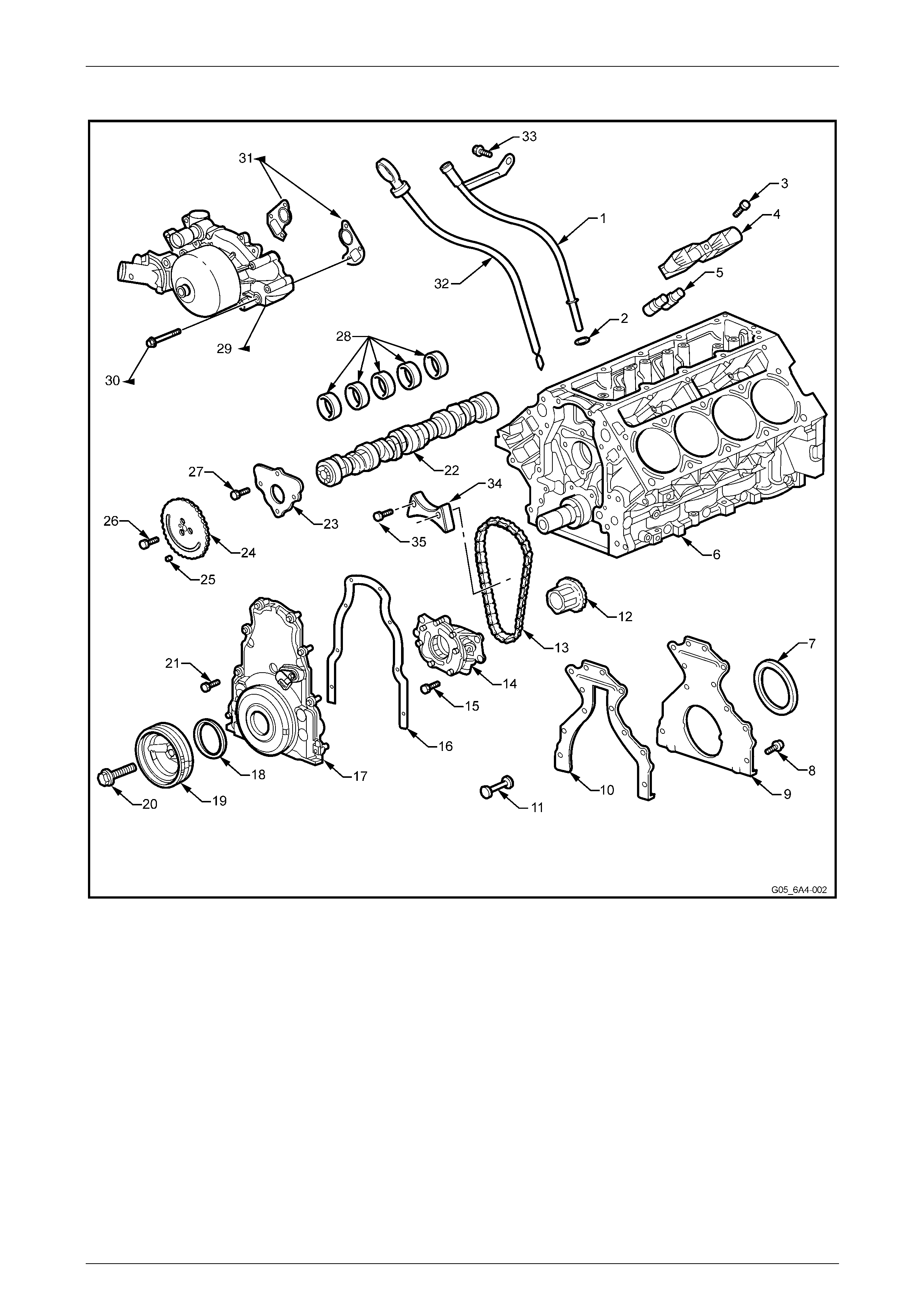
Lower Front of Engine
Figure 6A4 – 2
Legend
1 Oil Level Indicator Tube
2 Oil Level Indicator Tube O-ring
3 Valve Lifter Guide Bolt
4 Valve Lifter Guide
5 Valve Lifter
6 Engine Block
7 Crankshaft Rear Oil Seal
8 Engine Rear Cover Bolt,
11 places
9 Engine Rear Cover
10 Engine Rear Cover Gasket
11 Engine Block Rear Oil Gallery
Plug
12 Crankshaft Sprocket
13 Camshaft Timing Chain
14 Oil Pump Assembly
15 Oil Pump Assembly Bolt
16 Engine Front Cover Gasket
17 Engine Front Cover
18 Crankshaft Front Oil Seal
19 Crankshaft Balancer
20 Crankshaft Balancer Bolt
21 Engine Front Cover Bolt, 10 places
22 Camshaft
23 Camshaft Retainer
24 Camshaft Sprocket
25 Camshaft Sprocket Locating Pin
26 Camshaft Sprocket Bolt
27 Camshaft Retainer Bolt, 4 places
28 Camshaft Bearings
29 Coolant Pump
30 Coolant Pump Bolt, 6 places
31 Carrier Gaskets – Coolant Pump
32 Oil Level Indicator
33 Oil Level Indicator Tube Bolt
34 Chain Dampener
35 Chain Dampener bolt, 2 places
Engine Mechanical – HSV – Gen IV V8 Page 6A4–6
Page 6A4–6
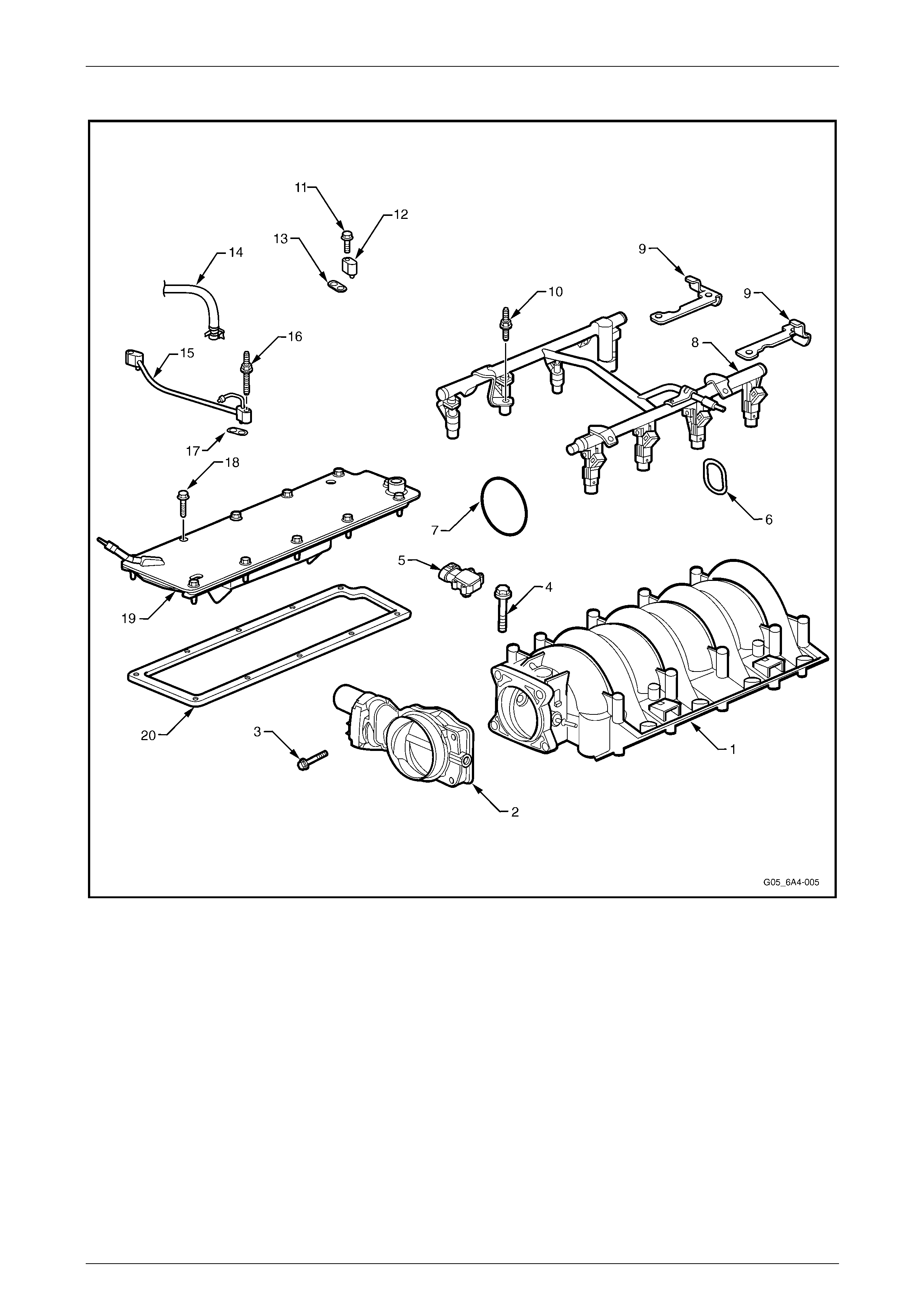
Intake Manifold – Upper Engine
Figure 6A4 – 3
Legend
1 Intake Manifold
2 Throttle Body
3 Throttle Body Bolt, 4 places
4 Intake Manifold Bolt, 10 places
5 Manifold Absolute Pressure (MAP) Sensor
6 Intake Manifold Gaskets, 8 places
7 Throttle Body O-ring
8 Fuel Rail
9 Fuel Rail Stop Brackets
10 Fuel Rail Stud, 4 places.
11 Vapour Vent Tube Bolt, 2 places
12 Vapour Vent Cover, 2 places
13 Vapour Vent Cover Gasket, 2 places
14 Vapour Vent Hose
15 Vapour Vent Tube
16 Vapour Vent Tube Stud
17 Vapour Vent Tube Gasket
18 Valley Cover Bolt, 11 places
19 Valley Cover
20 Valley Cover Gasket
Engine Mechanical – HSV – Gen IV V8 Page 6A4–7
Page 6A4–7
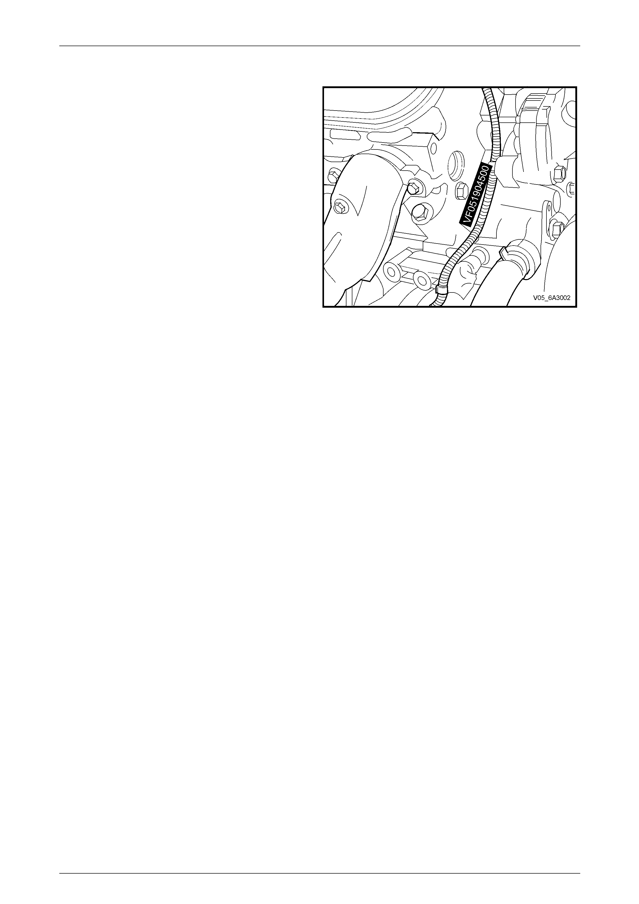
1.2 Engine Number
The engine serial number is stamped on the right-hand side
at the front of the engine cylinder bl ock. The number is
prefixed by two letters. As an example, (VF) is used.
The following is a breakdown of the engine numbering
system using VF051904500 a s an example;
• The first two numbers, 05 = 2005 i ndicates the engine
model year.
• The next three numbers, 190 i s the Julian date, which
is the day of the year the engine was manufactured.
• The next four numbers are the daily sequential build
number.
Figure 6A4 – 4
Engine Mechanical – HSV – Gen IV V8 Page 6A4–8
Page 6A4–8
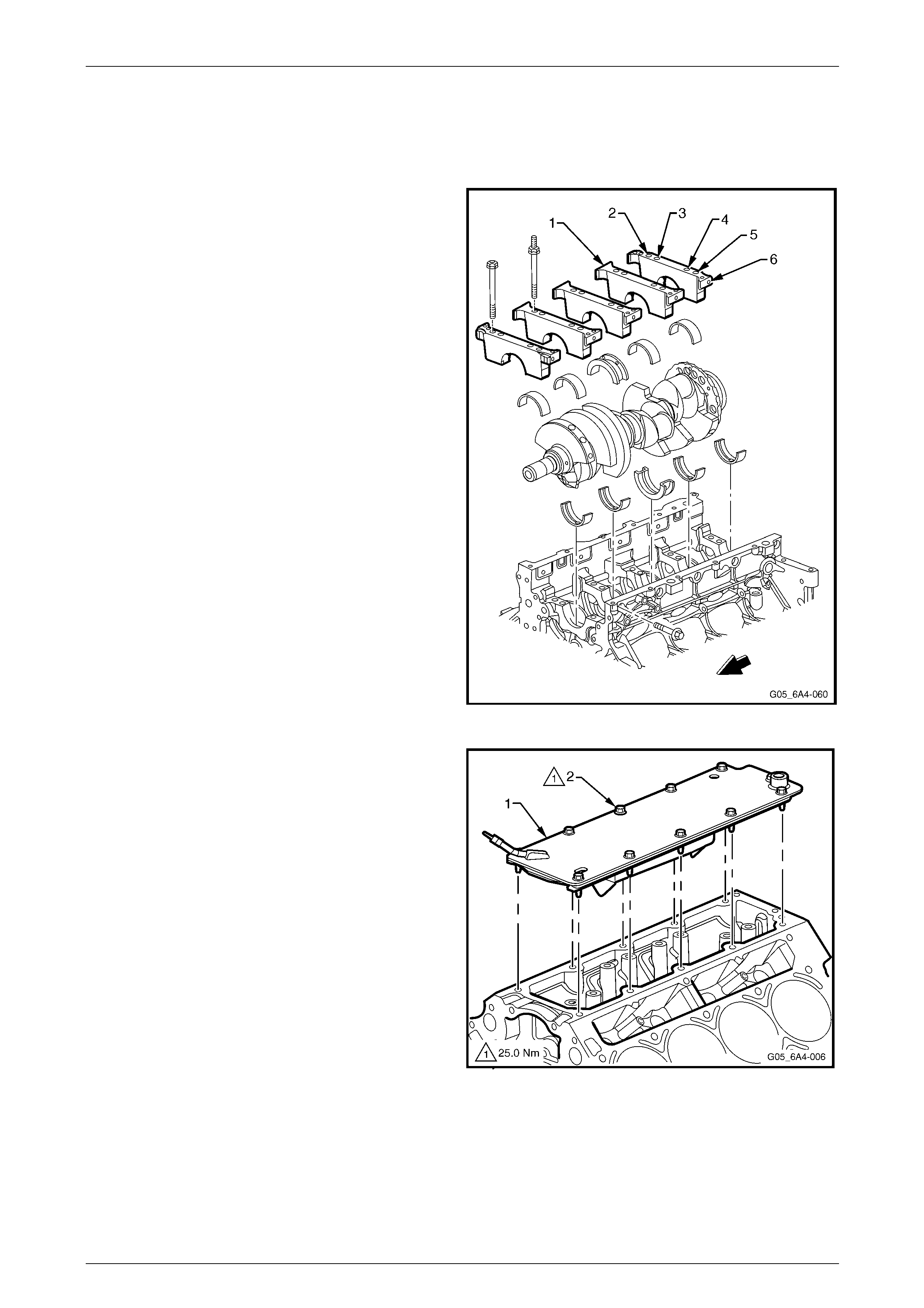
1.3 Engine Construction
Cylinder Block
The engine cylinder block is a cam-in-block, deep skirt, 90°
V configuration with five crankshaft bearing caps,
manufactured from forged powdered metal. The engine
block is aluminium with cast-in-place cast iron cylinder bore
liners. The five cross-bolted cr ankshaft bearing caps each
have four vertical M10 (2, 3, 4, and 5) and two horizontal M8
(1 and 6) mounting bolts. The cylinder bore must not be
bored and only cylinder bore honing is permitted.
The crankcase skirt length, bearing cap width, deck width
and upper rails have been optimised for strength using finite
element analysis.
The camshaft is supported by five camshaft bear ings
pressed into the block.
Figure 6A4 – 5
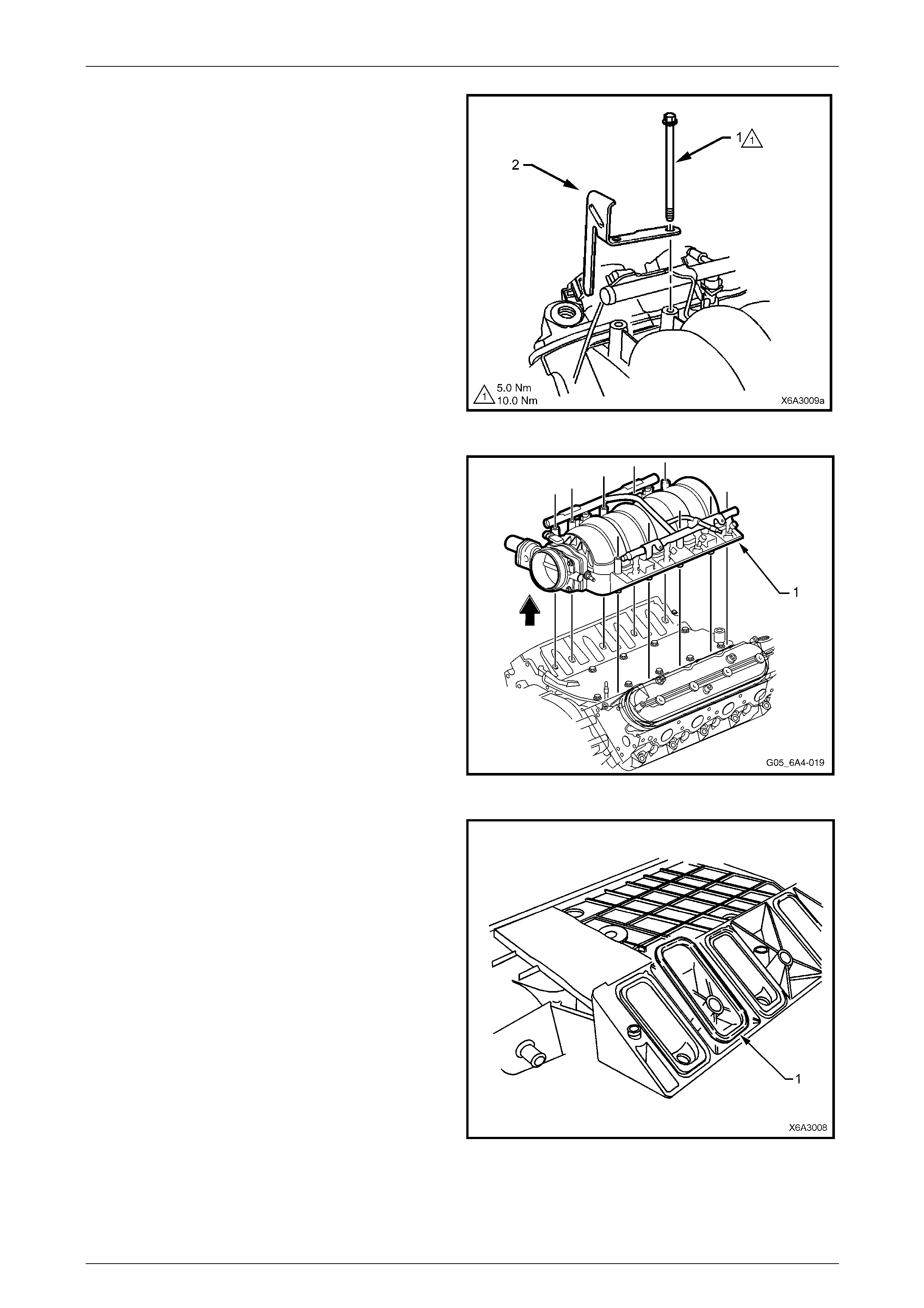
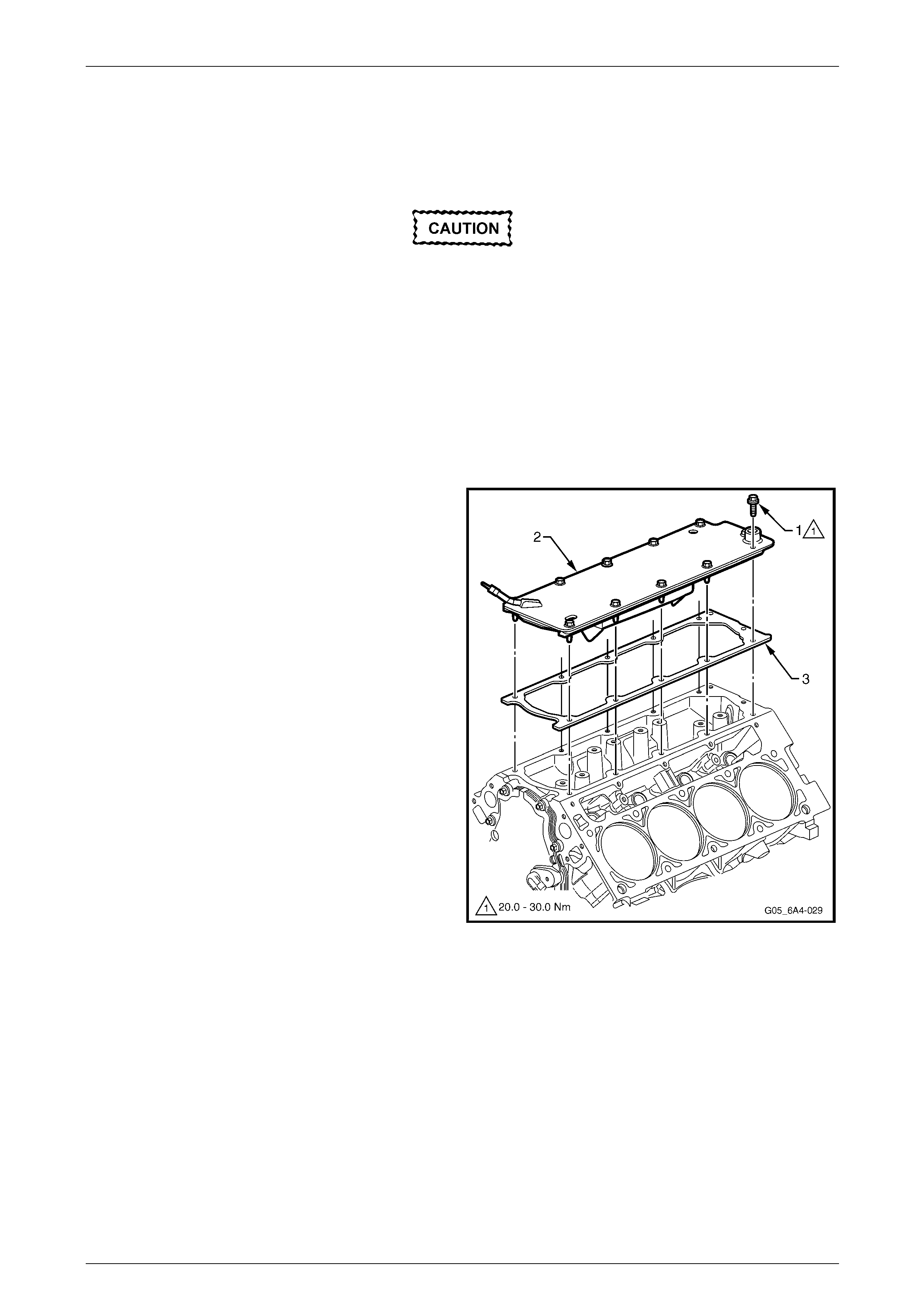
A structural die cast aluminium valley cov er (1) is attached
to the block using 11 M6 bolts (2). Having a closed valley
area prevents hot oil from contacting the lower surface of
the intake manifold. This allo ws cooler air to enter the
cylinders.
The cylinder block incorporates enclosed valve lifter bores
under each cylinder head that results in a mo re stiff
structure with quieter operation.
Overall, the cylinder block construction weighs 48% less
than an equivalent cast iron block. This structural d esig n
combined with the aluminium cylinder heads results in a
lightweight engine with unique stiffness.
Figure 6A4 – 6
Engine Mechanical – HSV – Gen IV V8 Page 6A4–9
Page 6A4–9
The additional hei ght of the intake ports is designed to
enhance fuel injector targeting. As the air flows down to the
valve guide, it widens and narrows to the size of the intake
valve seat.
Figure 6A4 – 7
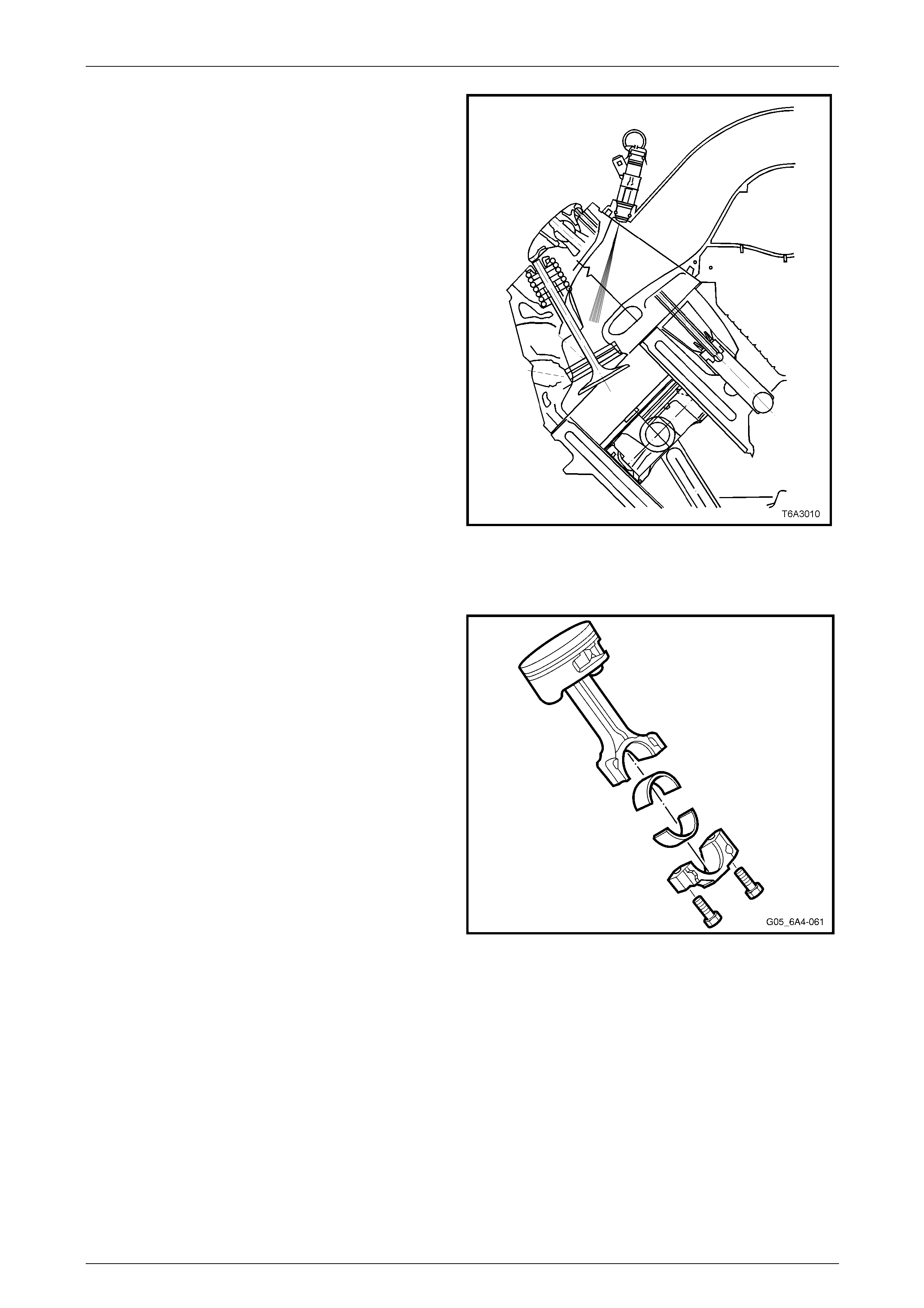
Pistons and Connecting Rods
The pistons are manufactured from cast alu minium. They
are fitted with two compression rings and one oil control ring
assembly. The piston rings are a thin, low friction design.
The top ring is located close to the top of the piston crown to
reduce hydrocarbon emissi ons entering the crankcase. The
pistons are a low friction lightweight design with a flat top
and barrel shaped skirt.
The piston pins are "chromium steel" and are a floating fit.
Each pin is retained in the pist on using a full circumference
retainer clip on each side.
The connecting rods are forged powdered metal. The
connecting rod cap is separated during the manufacturing
process using the fracture method. This creates a stronger,
visually seamless rod to cap union. The reassembled rod is
then machined for the correct clearance.
A 0.25 mm oversize piston and piston ring set are available
for service should cylinder honing be required.
Figure 6A4 – 8
Engine Mechanical – HSV – Gen IV V8 Page 6A4–10
Page 6A4–10
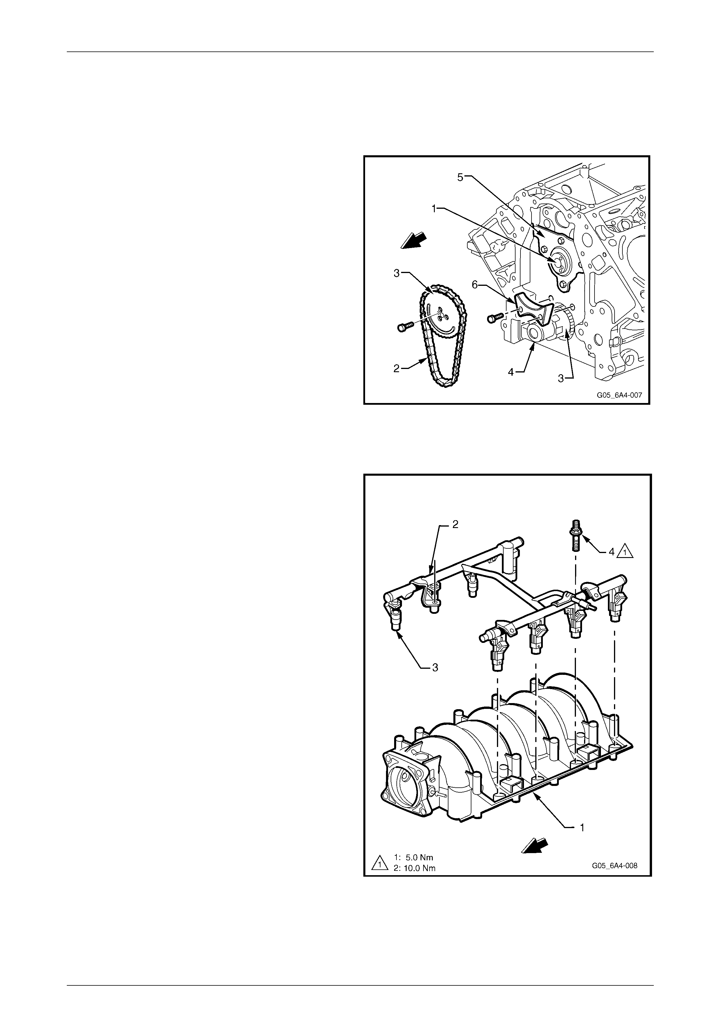
Camshaft and Drive
The camshaft is machined from a one-piece steel billet. It is supported by five bearings that are pressed into the engine
block. The intake and exhaust cam lobes have slow closing velocity ramps to reduce valve train noise. The camshaft
also has a 17 mm hole drilled down its length to reduce weight.
The camshaft (1) is driven by a traditional 9.52 mm pitch
roller chain (2) and powdered metal timing sprockets (3)
mounted to the front of the camshaft and crankshaft (4).
The crankshaft sprocket is splined internally and also drives
the oil pump driven gear. A retaining p late (5) mounted to
the front of the engine block maintains the ca mshaft
location. A timing chain dampener (6) is used to reduce
chain noise and resonance and is attached to the engine
block just above the crankshaft timing gear.
Figure 6A4 – 9
Intake Manifold
The intake manifold (1) is a one-piece composite design that
incorporates metal threaded inserts for attaching the fuel rail
(2) and the throttle body.
The intake manifold is sealed to the cylinder heads by eight
separate non-reusable si licone gaskets, which press into the
grooves of the intake housing.
The electronic controlled throttle body assembly bolts to the
front of the intake manifold. The throttle body is sealed to
the intake manifold by a one piece push in place silicone
gasket.
The fuel rail assembly has eight separate fu el injectors (3)
and is attached to the intake manifold by four studs (4). The
injectors are seated in their individual manifold bores with O-
ring seals to provide sealin g.
Fuel rail stop brackets are positioned both sides at the rear
of the fuel rail and are attached by the intake manifold
attaching bolts, refer to Figure 6A4 – 26.
There are no coolant passage s within the intake manifold.
The Manifold Absolute Pressure (MAP) sensor is instal led in
the front of the Intake manifold and is sealed by an O-ring
seal, refer to 2.1 Manifold Absolute Pressure Sensor.
Figure 6A4 – 10
Engine Mechanical – HSV – Gen IV V8 Page 6A4–11
Page 6A4–11
1.4 Engine Lubrication System
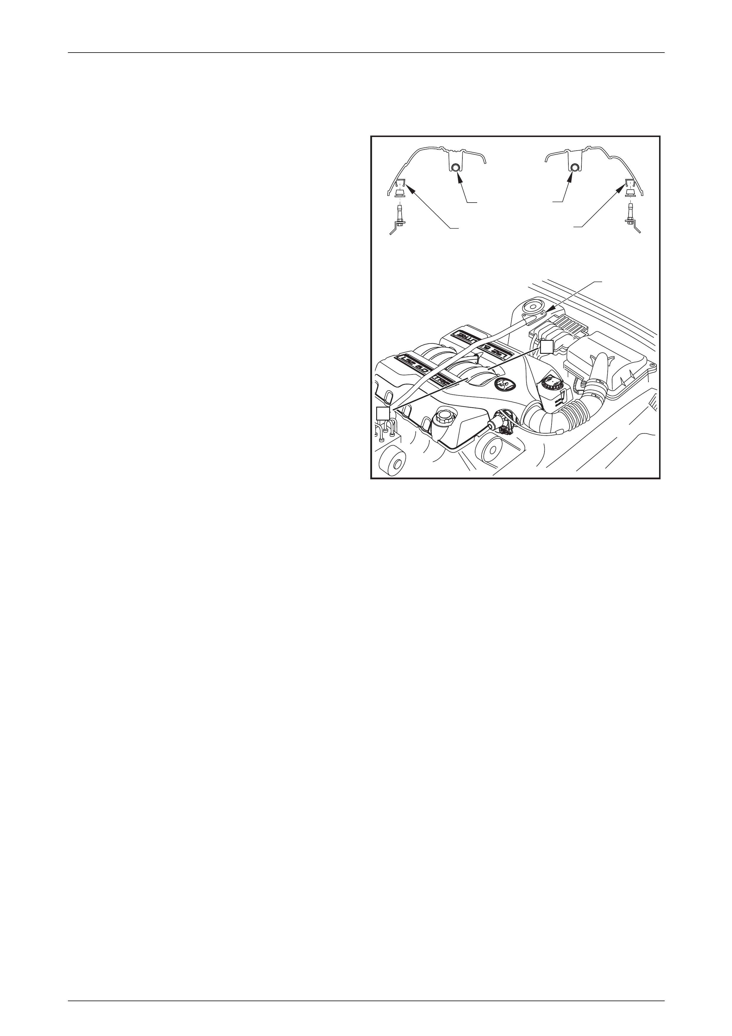
Positive Crankcase Ventilation System
The crankcase ventilation s ys t em was developed to remove
the engine combustion blow-by vapours and minimise the
following:
• Crankcase pressure build-up
• Oil deterioration
• Oil consumption
• Evaporative/exhaust emissions
During normal idle and part throttle operation, filtered fresh
air is routed from upstream of the throttle body (1) blade to
the front of the right-hand rocker cover via the fresh air inlet
hose (2).
Blow-by gas (oil vapour) in the crankcase valley passes
through the oil separator (3) attached to the valley cover and
then flows through the fixed internal flow-restricting orifice
within the valley cover (4) then via the foul air hose (5). The
blow-by gas is directed from the valley cover right-hand
corner to the Intake manifold on the engine side of the
throttle plate.
Under heavy load operation and high engine speeds, an
acceptable reverse flow condition may occur in the fresh air
inlet hose.
Figure 6A4 – 11
During sustained maximum lateral acceleration (A), the
outboard rocker cover may be overlo aded with oil (1). If the
blow-by gas is dra wn from the rocker cover as in previous
designs oil may be ingested i nto the intake manifold.
The Central Valley Ventilation System is designed to
eliminate oil ingestion during severe vehicle cornering
manoeuvres.
Instead of the blow-by gas be ing drawn from the rocker
cover, a high efficiency oil separator (2) in conju nction with
an internal flow-restricting orifice (3) is fitted under the valley
cover to draw the blow-by gas from the crankcase (B).
Figure 6A4 – 12
Engine Mechanical – HSV – Gen IV V8 Page 6A4–12
Page 6A4–12
2 Minor Service Operations
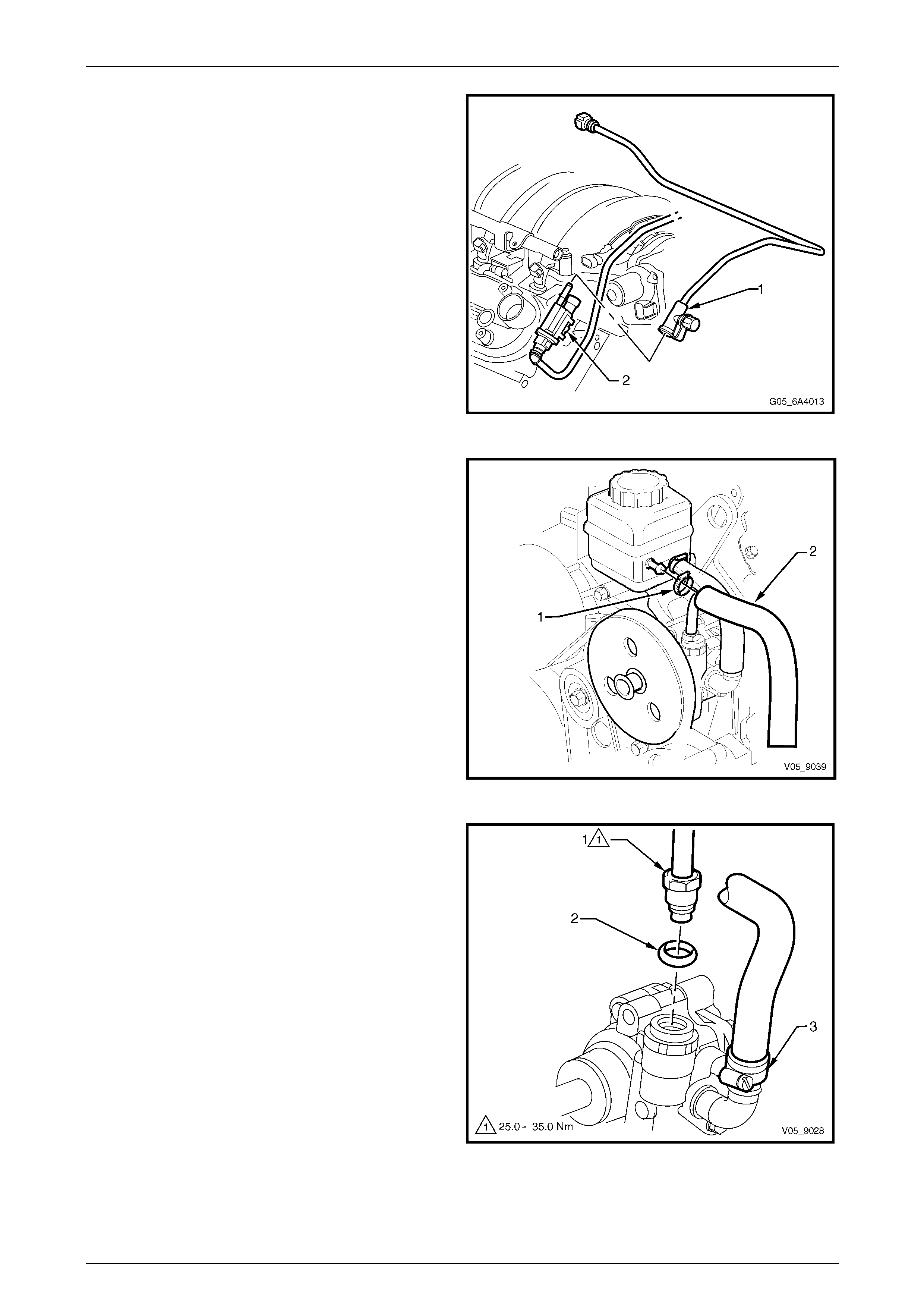
2.1 Manifold Absolute Pressure Sensor
Remove
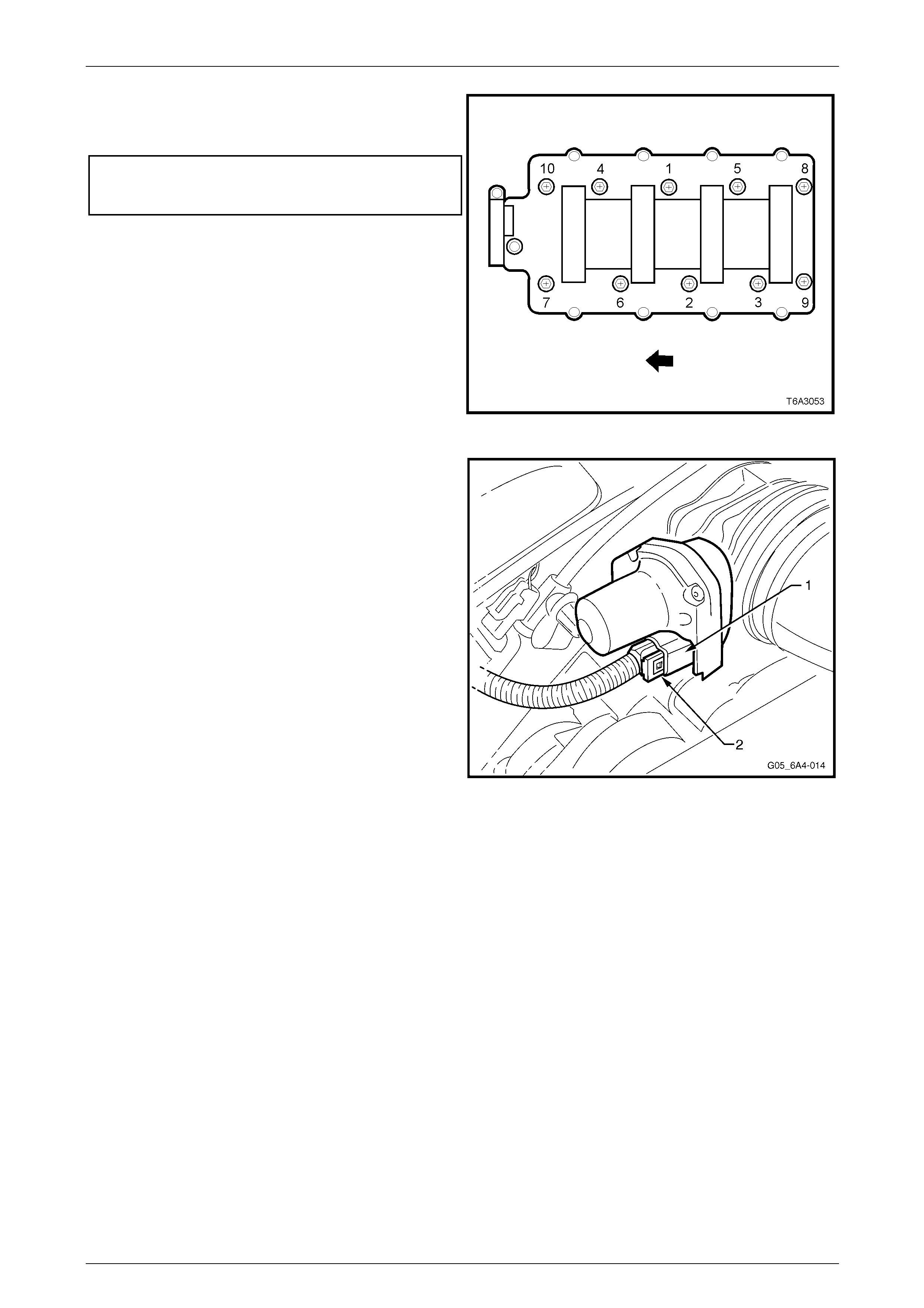
1 Release the wiring harness connector locking tang (1)
from the manifold absolute pressure (MAP) sensor (2),
located at the front of the intake manifold and then
remove the connector from the sensor
Figure 6A4 – 13
2 Grasp the MAP sensor (1) and twist back and forth
while pulling up wards to remove it from the manifold.
3 Check the silicone rubber sea l (2) on the MAP sensor
to ensure it is not torn or damaged. Replace as
required.
Figure 6A4 – 14
Reinstall
1 Reinstall the MAP sensor by pushing it down into the fitting at the front of the intake manifold.
2 Reinstall the wiring harness connector to the MAP sensor ensuring that the locking tab is in place.
3 Start the engine and check for correct operat ion.
Engine Mechanical – HSV – Gen IV V8 Page 6A4–13
Page 6A4–13
2.2 Intake Manifold
Remove
Disconnection of the battery affects certain
vehicle electronic systems. Refer to
Section 00, 5. Battery Disconnection
Procedures in the MY 2004 Holden VZ Ser vice
Information before disconnecting the battery.
NOTE
Unless components such as the throttle body,
fuel injection rail and/or injectors are to be
removed individually, the n it is recommende d that
the complete intake manifold assembly be
removed.
1 Disconnect the negative battery cable from the battery.
2 Drain the cooling system. Refer to Section 6B4 Engine Cooling – GEN IV V8.
3 Remove the strut tower brace. Refer to Section 1A1 Body in the MY 2004 Hold en VZ Service Information.
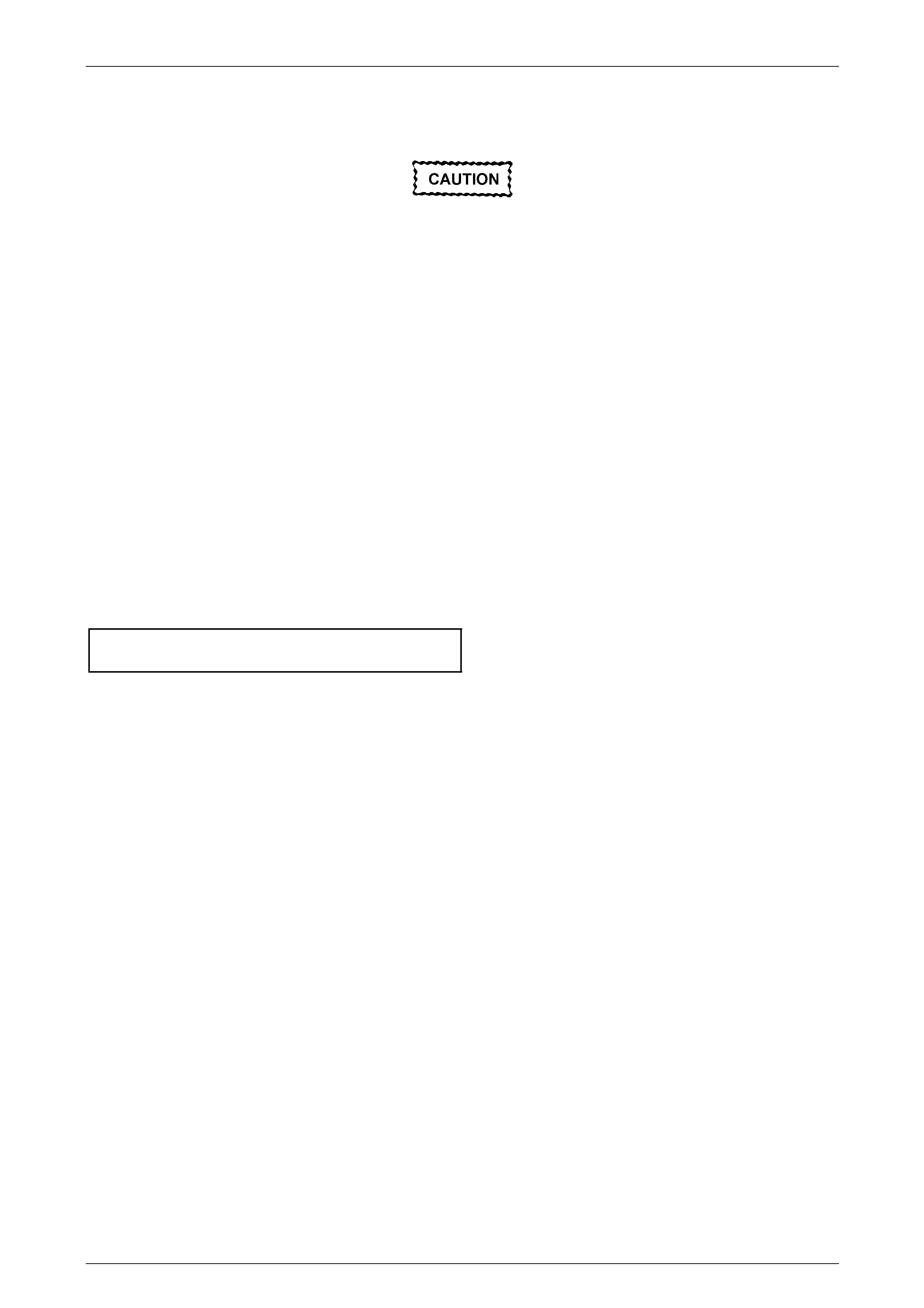
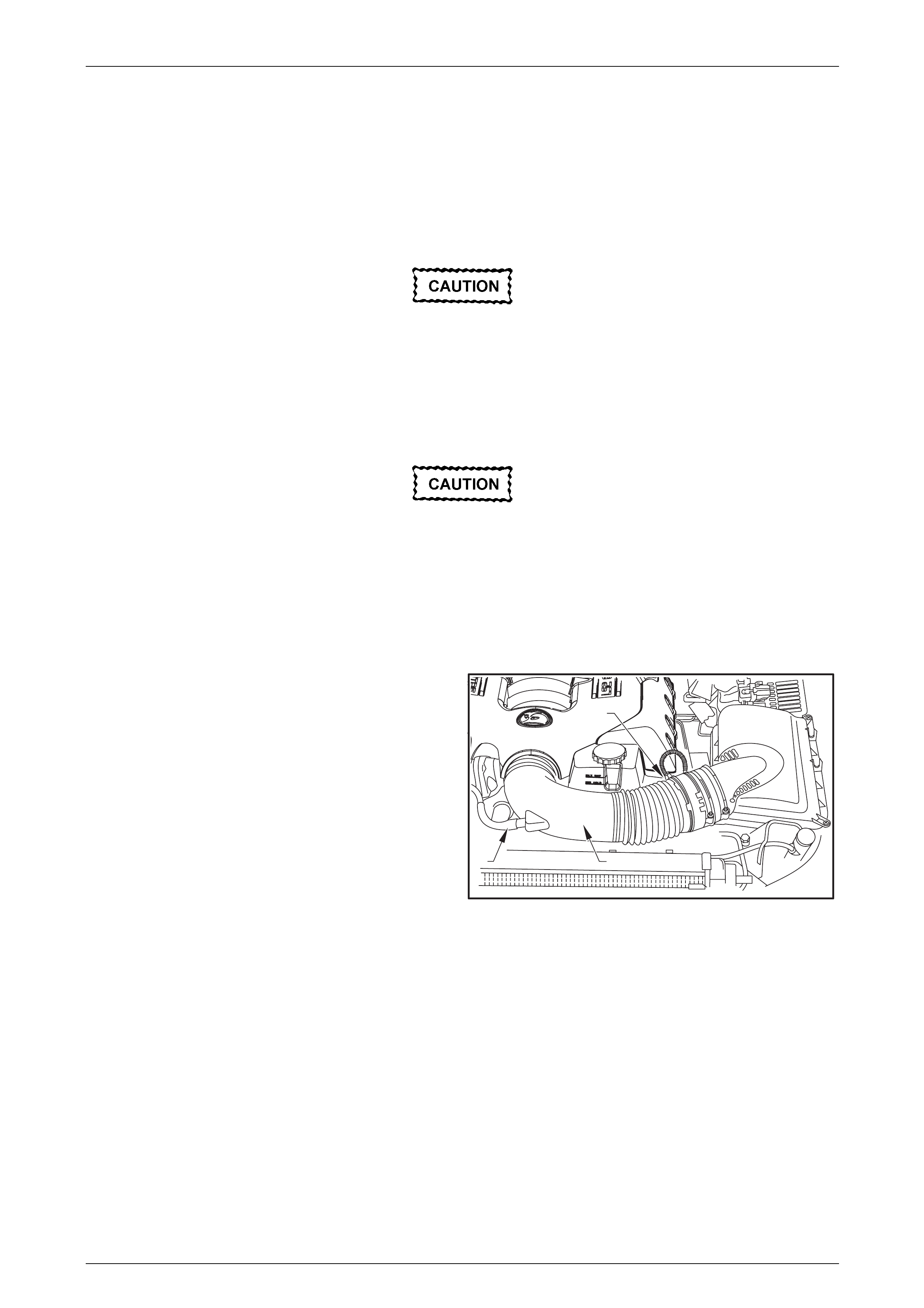
4 Remove the fresh air hose (1) from the air intake duct
(2) and lay it to the side of the engine.
5 Remove the air intake sensor wiring harness
connector (3).
6 Loosen the hose clamps attachin g the intake duct to
the air box and the throttle body and remove the duct
from the engine.
7 Remove the duct from the engine.
8 Remove the engine dress covers, refer to
2.6 Engine Dress Cover.
9 De-pressurise the fuel rail. Refer to
Section 8A1 Fuel System in the MY 200 4 Holden VZ
Service Information.
12
3
Figure 6A4 – 15
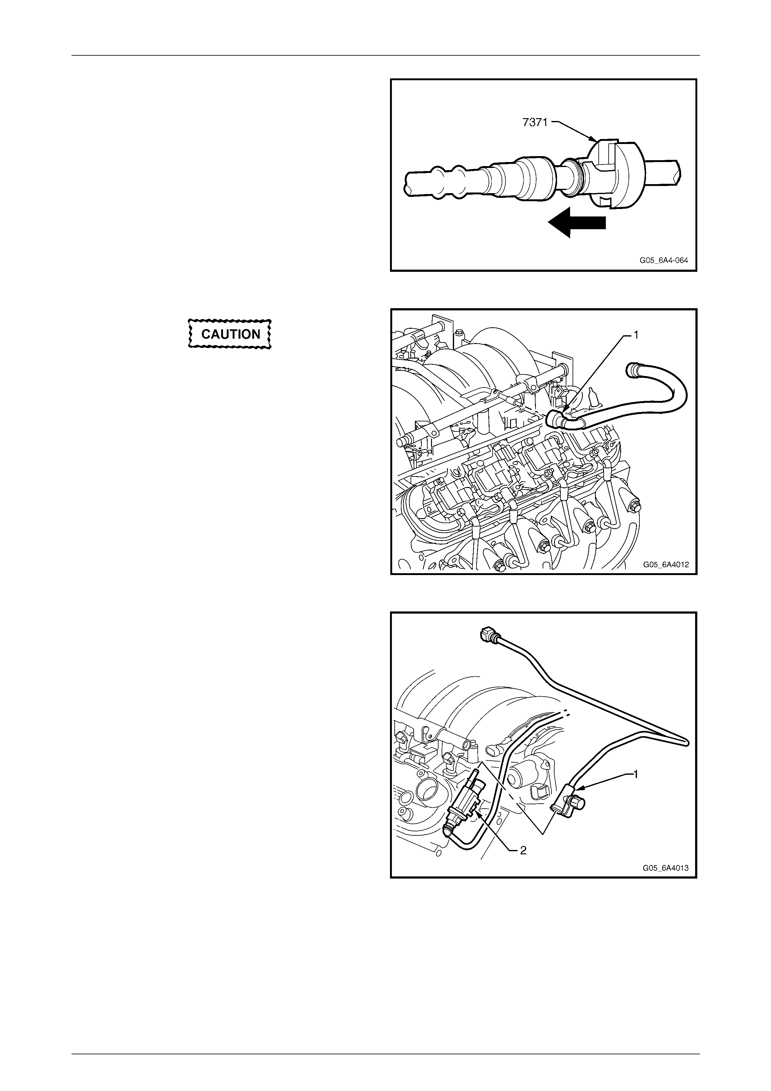
10 Using a small scre wdriver, release the s ecurity lock
(1), at each of the fuel supply hose quick connect
fittings (2).
NOTE
The security lock at the fuel rail side onl y, is fitted
to a tether to prevent loss.
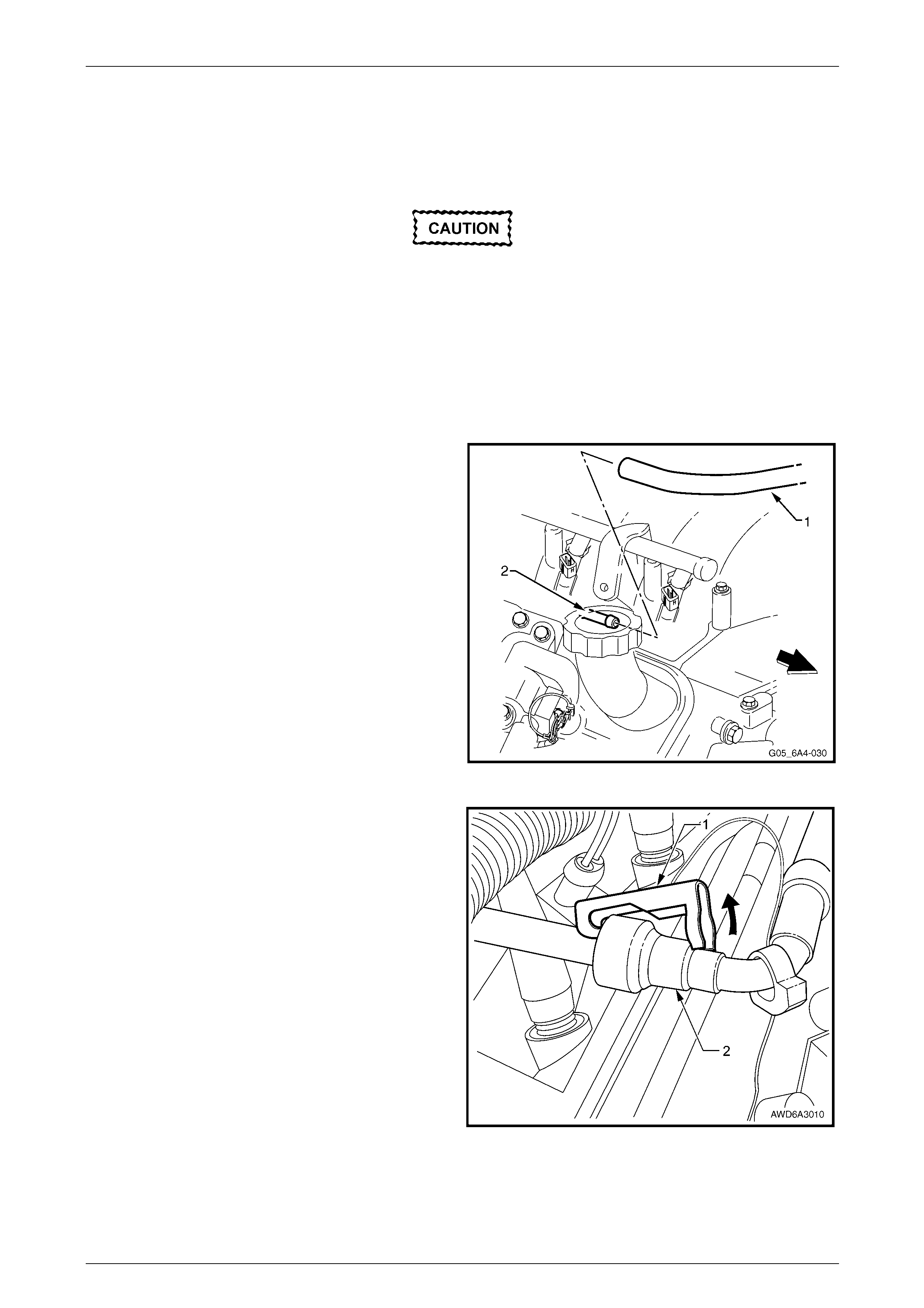
11 Install the quick connect release Tool No. 7371 over
the fuel line, refer to Section 6C4 Powertrain
Management – GEN IV V8.
Figure 6A4 – 16
Engine Mechanical – HSV – Gen IV V8 Page 6A4–14
Page 6A4–14
Ensure the fuel system has been
depressurised before removing the fuel line
from the fuel rail, refer to Section 8A1 Fuel
System in the MY 2004 Holden VZ Service
Information.
12 While holding the fuel l in e quick connect (1), push on
Tool 7371 to release the qu ick connect fitting from the
fuel rail. Pull back on the quick connect and remove
the fuel line.
Figure 6A4 – 17
13 Disconnect the electronic throttle control body wiring
harness connector (1) from the throttle body by
removing the connector lock (2) and the n pulling on
the connector.
Figure 6A4 – 18
Engine Mechanical – HSV – Gen IV V8 Page 6A4–15
Page 6A4–15
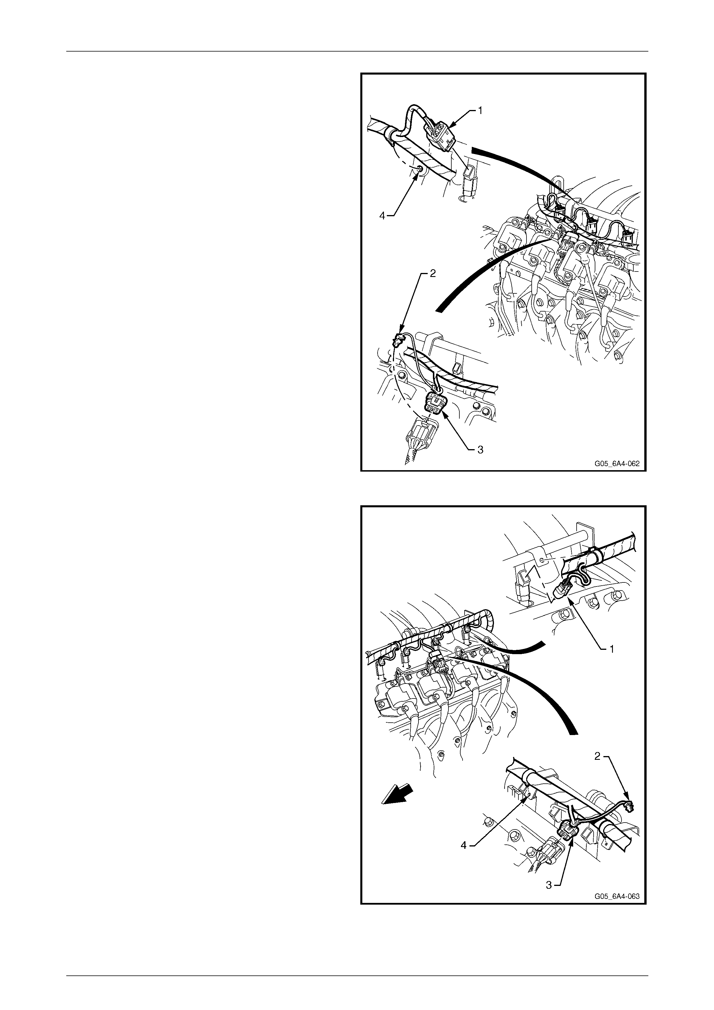
14 Disconnect the fuel injector wiring harness connectors
(1), four places, from the right-hand bank of fuel
injectors.
15 Remove the CPA lock (2) from the ignition coil mai n
connector (3) on the right-hand side. Remove the
connector then the harness attaching clips fr om the
fuel rail brackets (4) and set the harness to one sid e.
Figure 6A4 – 19
16 Disconnect the fuel injector wiring harness connectors
(1), four places, from the left-hand bank of fuel
injectors.
17 Remove the CPA lock (2) from the ignition coil mai n
connector (3) on the left-hand side, then rem ove the
connector.
18 Remove the wiring harness connector from the
canister purge valve (4).
19 Remove the harness securing clips from the fuel rail
brackets (5) and set the harness to one side.
20 Disconnect the manifold absol ute pressure (MAP)
sensor wiring harness connector, refer to
2.1 Manifold Absolute Pressure Sensor.
Figure 6A4 – 20
Engine Mechanical – HSV – Gen IV V8 Page 6A4–16
Page 6A4–16
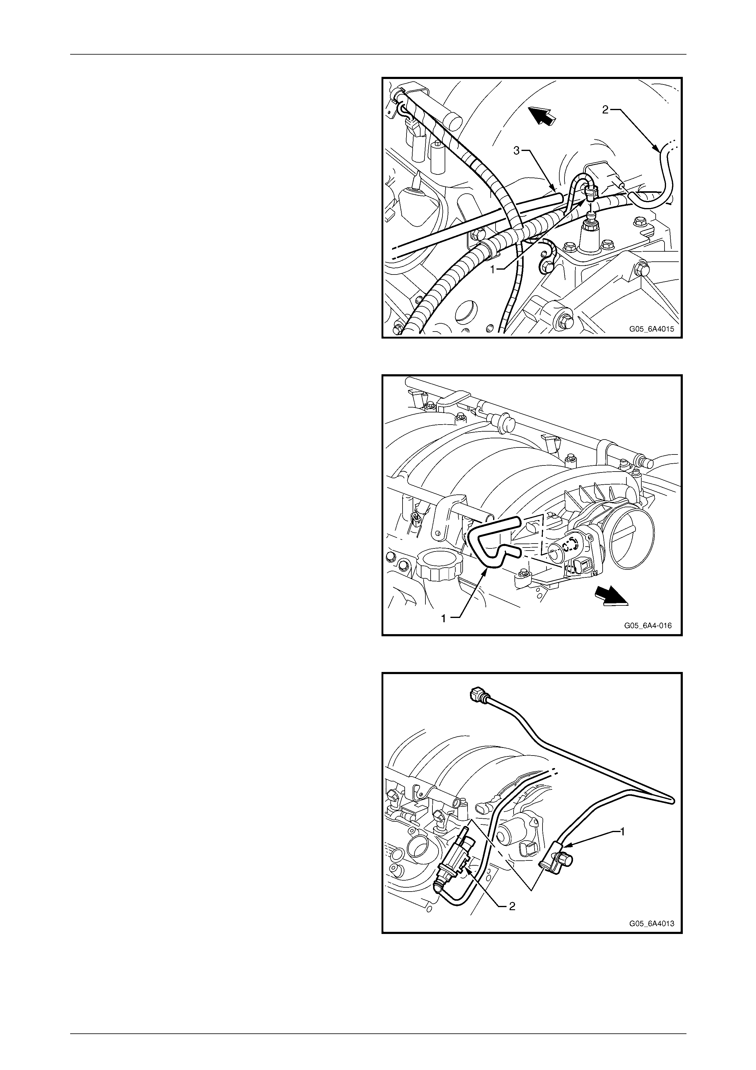
21 Disconnect the oil pressure sensor wiring harness
connector (1).
22 Remove the HVAC vacuum hose (2) and the brake
booster hose (3).
Figure 6A4 – 21
23 Remove the foul air hose (1) from the throttle body
and the restricting orifice external connector from the
valley cover.
Figure 6A4 – 22
24 Disconnect the EVAP purge valve vapour line
connector (1) from the EVAP purge valve (2).
NOTE
Cap the fuel line fittings and plug the holes after
separating the fuel lines to prevent fuel leaking
and/or dirt and other contaminants from e ntering
the fuel system.
Figure 6A4 – 23

Engine Mechanical – HSV – Gen IV V8 Page 6A4–17
Page 6A4–17
25 Remove the evaporative (EVAP) canister purge valve
tube (1) from the purge valve (2) and the intake
manifold (3).
Figure 6A4 – 24
26 Remove the bolt (1) attaching the EVAP canister
purge valve and bracket assembly (2) from the right-
hand cylinder head.
NOTE
It is recommended to remove the purge valve
from the cylinder head to avoid damage to the
valve when removing the Intake manifold.
Figure 6A4 – 25
Engine Mechanical – HSV – Gen IV V8 Page 6A4–18
Page 6A4–18
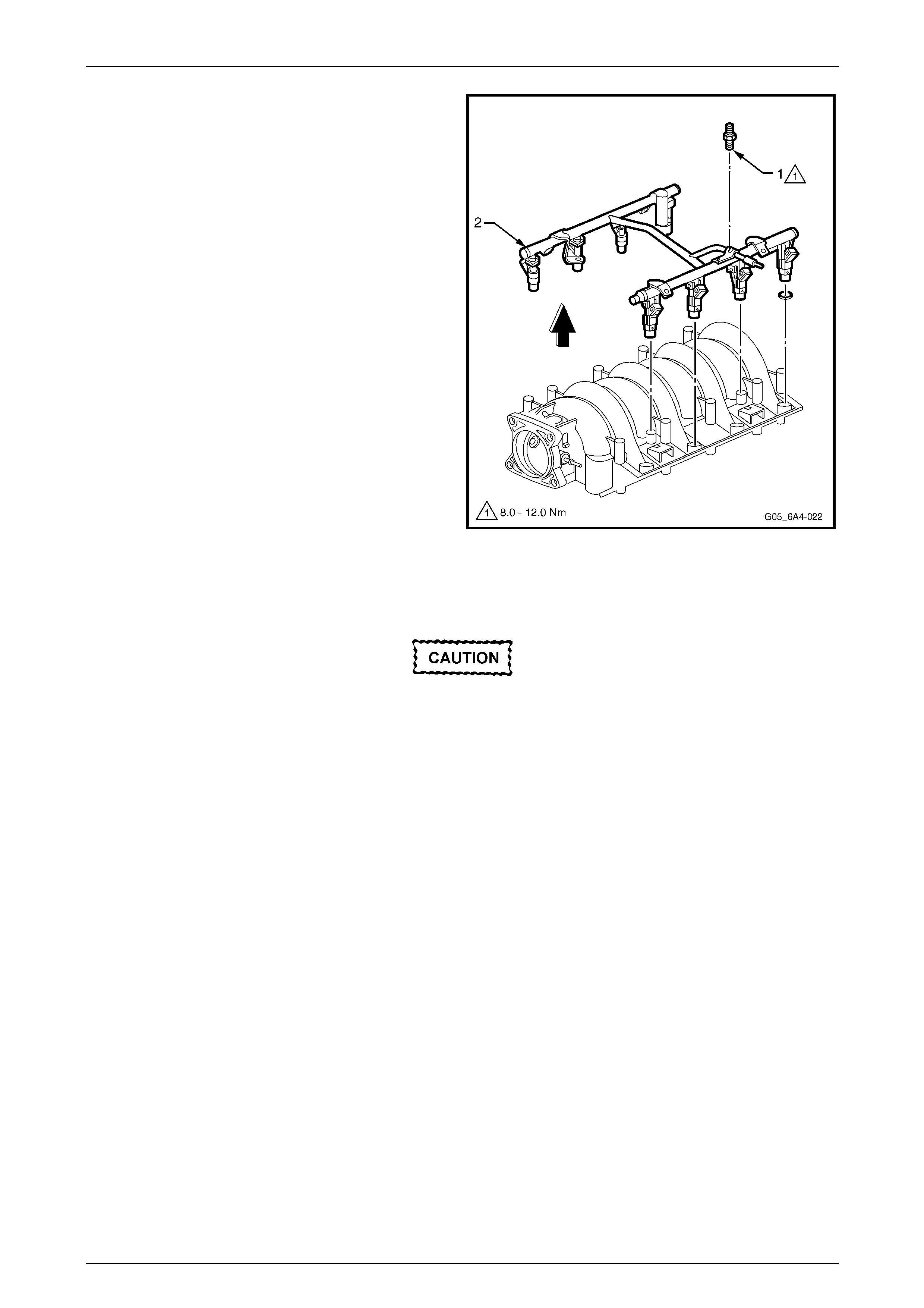
27 Progressively loosen all the intake manifold retaining
bolts (1), working diagonally from outside to inside.
28 Remove the fuel rail stop bracket (2), two places and
set to one side.
NOTE
The fuel rail stop brackets are attache d using the
two rear bolts on each sid e (3, 9, 5 and 8) of the
Intake manifold. Refer to Figure 6A4 – 36.
Figure 6A4 – 26
29 Carefully tap the intake manifold assembly (1) with a
rubber mallet to break the gasket seal and then lift it
from the engine.
Figure 6A4 – 27
30 Remove the intake manifold to cylinder head gaskets
(1) and discard the gaskets.
NOTE
New Intake manifold gaskets must be used
when reinstalling the Intake manifold.
Figure 6A4 – 28
Engine Mechanical – HSV – Gen IV V8 Page 6A4–19
Page 6A4–19
Disassemble
If required, remove the following components from the intake manifold
1 Remove the Manifold Absolute Pressure (MAP) sensor from the intake manifold, refer to
2.1 Manifold Absolute Pressure Sensor.
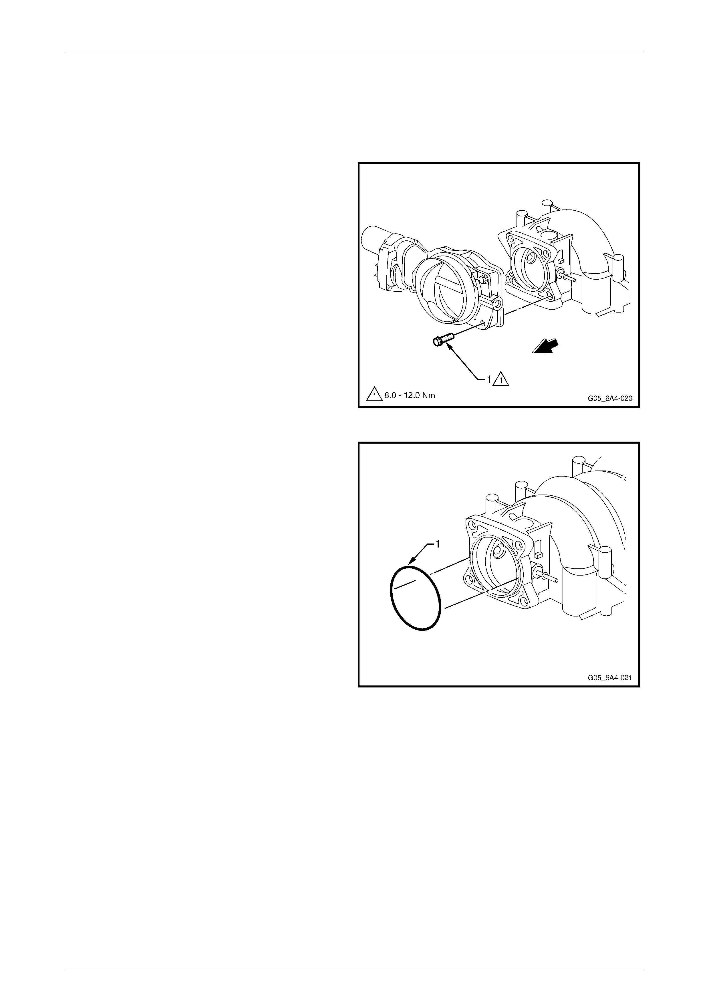
2 Remove the throttle body attaching bolt (1), four
places and remove the throttle bod y.
Figure 6A4 – 29
3 Remove the throttle body O-ring (1) from the Intake
manifold and discard.
NOTE
Do not re-use the throttle body O-ring.
Figure 6A4 – 30
Engine Mechanical – HSV – Gen IV V8 Page 6A4–20
Page 6A4–20
4 Remove the four studs (1) attaching the fuel rail (2)
and injectors to the intake manifold and then carefully
remove the fuel rail and inject ors as an assembly.
NOTE
Should further disassembly of the fuel injectors
be required, refer to Section 6C4 Powertrain
Management – GEN IV V8.
Figure 6A4 – 31
Clean and Inspect
Wear the appropriate safety glasses and
gloves when using compressed air and
cleaning fluids to avoid eye and skin injury.
1 Clean the intake manifold in a commercially available clea ning fluid and then blow dry using compressed air.
2 Ensure that the intake manifold gasket grooves and the vacuum passages in the rear of the intake manifold are all
clean and clear from obstructions.
3 Inspect the throttle body and fuel rail bolt inserts in the intake manifold for looseness and/or dama ged threads,
repair as required. Refer to Section 6A3 Engine Mechanical - 5 Thread Repair in the MY 2004 Holden VZ Service
Information.
4 Inspect the intake manifold for cracks or damage includi ng the areas between the intake runners.
5 Inspect the fuel injector bores for excessive scoring or damage.
6 Inspect the intake manifold to cylinder head f aces for warpage as follows:
a Place a straight edge across each of the two surfaces and check for warpage using feeler gauges.
b An intake manifold with warpage in excess of 0.5 mm must be replaced.
Engine Mechanical – HSV – Gen IV V8 Page 6A4–21
Page 6A4–21
Reassemble
1 Reinstall the MAP sensor, refer to 2.1 Manifold Absolute Pressure Sensor.
Fuel Rail and Injectors
1 Lubricate the new injector O-ring seals (1), eight
places, with clean engine oil.
2 Install the new O-rings onto the fuel injectors.
3 Install the fuel rail and injector assembly (2) into the
intake manifold, pressing even ly on each side until the
injectors are all full y seated i n their bores.
4 Apply a 5 mm band of thread sealant such as Loctite
242 or equivalent to the cleaned threads of the fuel rail
attaching studs (3), four places, and install.
5 Tightening the studs to the correct torque
specification.
Fuel rail attaching studs
torque specification...................................8.0 – 12.0 Nm
Figure 6A4 – 32
Throttle Body
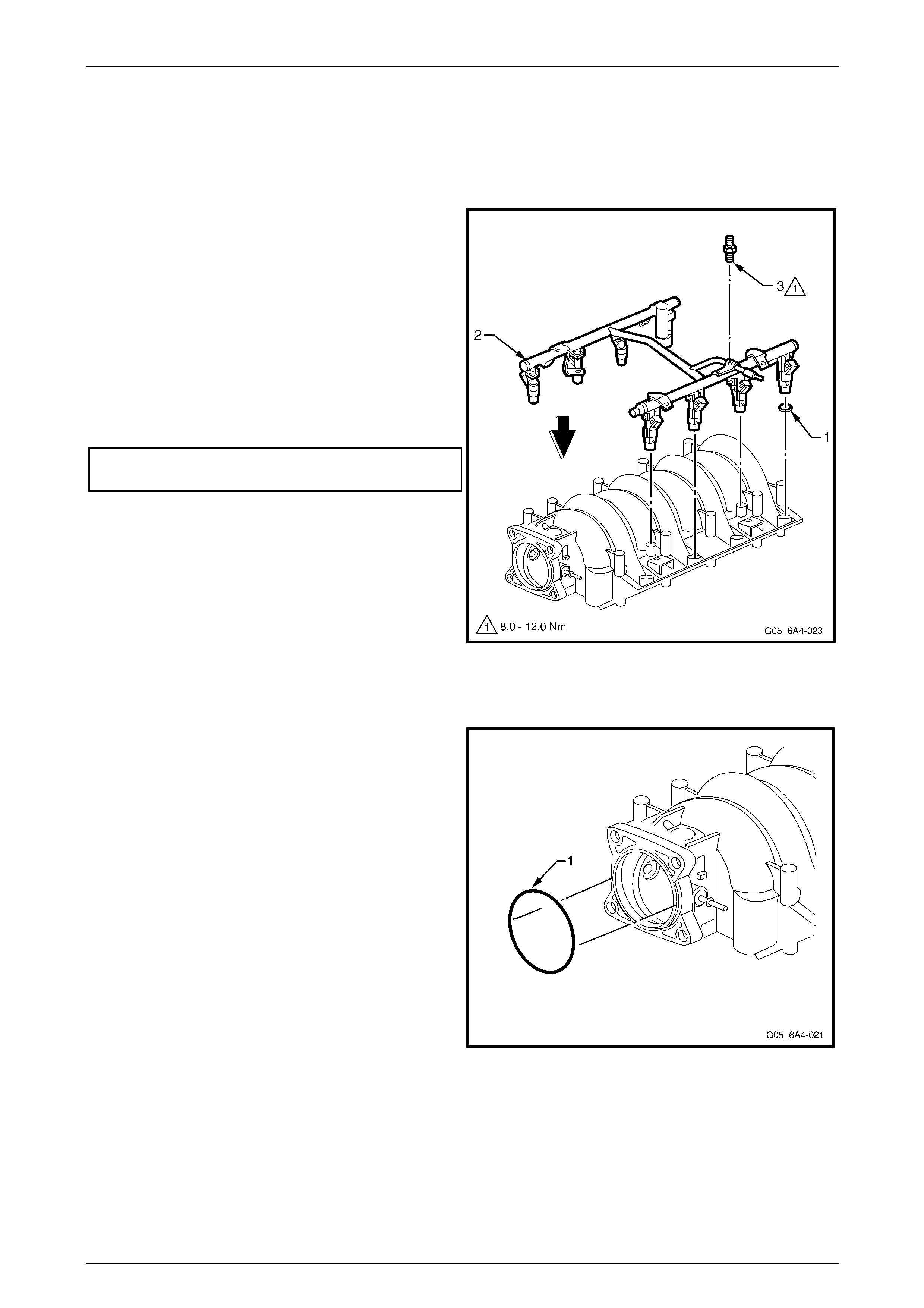
1 Install a new throttle body O-ring (1) to the intake
manifold, ensuring it is pressed firmly into place.
Figure 6A4 – 33
Engine Mechanical – HSV – Gen IV V8 Page 6A4–22
Page 6A4–22
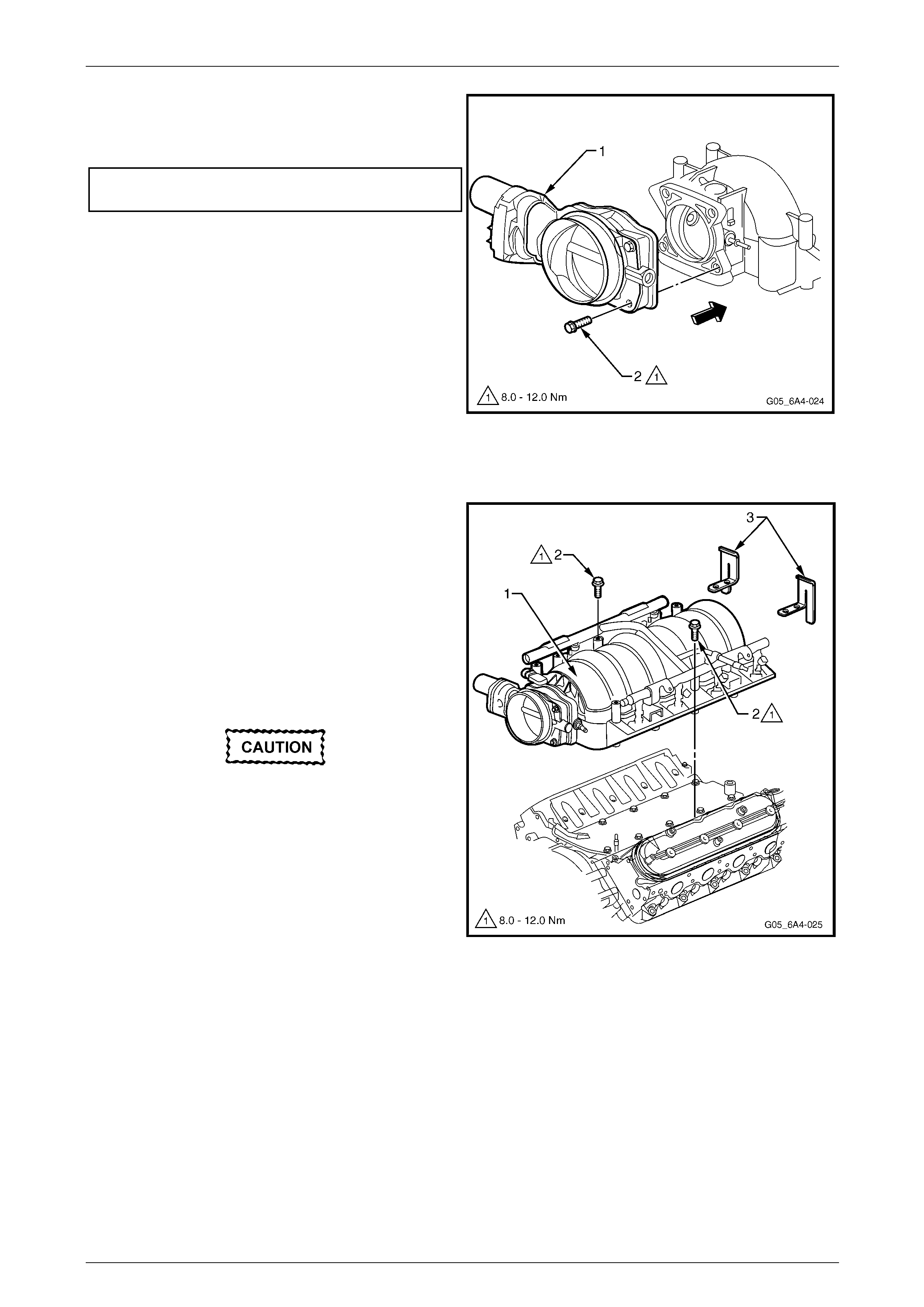
2 Install the throttle body (1), ho ldin g it in place by hand.
3 Install the throttle body attac hi ng bolt (2), four places,
and tighten to the correct torque specification.
Throttle body attaching bolt
torque specification...................................8.0 – 12.0 Nm
Figure 6A4 – 34
Reinstall
1 Install the eight ne w intake manifol d to cylinder head
gaskets, refer to Figure 6A4 – 28, and then carefully
lower the intake manifold assembly (1) to the cylinder
heads.
2 Apply a 5 mm band of thread sealant such as Loctite
242 or equivalent, to the cleaned threads of the two
intake manifold attaching bolts (2) and the n tighten
these by hand.
3 Apply a 5 mm band of thread sealant such as Loctite
242 or equivalent, to the cleaned threads of the eight
remaining intake manifold attaching bolts.
Do not overlook installing the two fuel stop
brackets (3). The stop brackets serve as a
protective shield for the fuel rails in the event
of a vehicle front end collision. If the fuel rail
stop brackets are not installed and the
vehicle is involved in a collision, the rails
may become damaged, causing the
pressurised fuel in the rails to leak, possibly
causing a fire and personal injury from
burns. The fuel stop b rackets are attached b y
bolts (3, 9, 5 and 8), refer to Figure 6A4 – 36.
4 Install the eight remaining i nta ke manifold bolts,
including the two at the rear on each side, which also
attach the fuel rail stop brackets.
Figure 6A4 – 35
Engine Mechanical – HSV – Gen IV V8 Page 6A4–23
Page 6A4–23
5 Tighten the ten intake manifold bolts in two stages in
the sequence shown to the correct torque
specification.
Intake manifold bolts torque specification
Stage 1 ................................................................5.0 Nm
Stage 2 .....................................................8.0 – 12.0 Nm
NOTE
The fuel stop brackets are attached by bolts
(3, 9, 5 and 8).
Figure 6A4 – 36
6 Reconnect the throttle body wiring harness connector
(1) and reinstall the connector lock (2).
7 The remainder of the intake manifo ld reinstallation
process is the reverse of the removal procedure.
Figure 6A4 – 37
Engine Mechanical – HSV – Gen IV V8 Page 6A4–24
Page 6A4–24
2.3 Engine Valley Cover
Remove
Disconnection of the battery affects certain
vehicle electronic systems. Refer to
Section 00, 5. Battery Disconnection
Procedures in the MY 200 4 Holden VZ Service
Information before disconnecting the battery.
1 Disconnect the negative battery cable terminal from the battery.
2 Drain the cooling system. Refer to Section 6B4 Engine Cooling – GEN IV V8.
3 Remove the intake manifold. Refer to 2.2 Intake Manifold.
4 Remove the vapour vent pipe. Refer to Section 6A3 Engine Mechanical – 3.8 Vapour Vent Pipe and Covers in the
MY 2004 Holden VZ Service Information.
NOTE
The valley cover can be removed without
removing the cylinder hea ds, however the heads
are not shown for clarity.
5 Remove the bolt (1), 11 places, attaching the
valley cover (2) to the c ylinder block.
6 Remove the valley cover and gasket (3) from the block
and discard the gasket.
Figure 6A4 – 38
Engine Mechanical – HSV – Gen IV V8 Page 6A4–25
Page 6A4–25
Clean and Inspect
Wear the appropriate safety glasses and
gloves when using compressed air and
cleaning fluids to avoid eye and skin injury.
1 Clean the valley cover in a commercially available cleaning fluid and b low dry using compressed air.
2 Clean the gasket surface with a plastic scrap er or similar.
NOTE
Do not use a metal scraper to remove gaskets.
as damage to aluminium components can occur
resulting in oil leaks.
3 Inspect the valley cover sealing surfaces for excessive scratches or other damage.
4 Ensure the fixed internal flo w-restricting or if ice is clean and free from foreign obstructions.
Reinstall
Reinstallation of the valley cover is the reverse of the removal procedure noting the following:
1 Install a new gasket to the valley cover and install the cov er to the engine.
2 Install the 11 valley cover attaching bolts a n d tighten to the correct torque specification.
Valley cover attaching bolt
torque specification.................................20.0 – 30.0 Nm
Engine Mechanical – HSV – Gen IV V8 Page 6A4–26
Page 6A4–26
2.4 Valve Rocker Arm Cover
Remove
Disconnection of the battery affects certain
vehicle electronic systems. Refer to
Section 00, 5. Battery Disconnection
Procedures in the MY 200 4 Holden VZ Service
Information before disconnecting the battery.
1 Disconnect the negative battery cable terminal from the battery.
2 If required, remove the strut tower brace, refer to Section 1A1 Body in the MY 2004 Holden VZ Service Information.
3 Remove the engine dress cover, refer to 2.6 Engine Dress Cover.
4 If required, remove the fresh air hose (1) from the
fitting (2) at the front of the right-hand valve rocker arm
cover.
Figure 6A4 – 39
5 Using a small scre wdriver, release the s ecurity lock
(1), at each of the fuel supply hose quick connect
fittings (2).
NOTE
The security lock, which is located at the fuel rail
side only, is fitted to a tether to prevent loss.
Figure 6A4 – 40
Engine Mechanical – HSV – Gen IV V8 Page 6A4–27
Page 6A4–27
6 Using the quick connect release Tool No. 7371, install
the tool over the fuel line. Refer to
Section 6C4 Powertrain Management – GEN IV V8.
Figure 6A4 – 41
Ensure the fuel system has been
depressurised prior to disconnecting the fuel
line. Refer to Section 8A1 Fuel System in the
MY 2004 Holden VZ Service Information.
7 While holding the fuel line quick connect fitting (1),
push on Tool No.7371 to release the quick connect
fitting from the fuel rail. Pull back on the quick connect
fitting and remove the line.
NOTE
Cap the fuel line fittings and plug the holes after
separating the fuel lines to prevent fuel leaking
and or dirt and other contam inants from entering
the fuel system.
Figure 6A4 – 42
8 Disconnect the EVAP purge valve vapour line
connector (1) from the EVAP purge valve (2).
Figure 6A4 – 43
Engine Mechanical – HSV – Gen IV V8 Page 6A4–28
Page 6A4–28
Handle the spark plug boot only. Do not pull
on the lead. To remove the lead, twist the
boot first to break the seal and then gently
pull on the boot.
9 Remove the spark plug leads.
Figure 6A4 – 44
10 Remove the CPA lock (1) from the ignition coil main
connector on the valve rocker arm cover that is being
removed and then remove the wiring harness
connector (2).
The rear attaching bolt on each coil assemb l y
is a conventional screw and not a stepped
stud. Fitment of this screw in the correct
position on reassembly is important to avoid
possible chaffing of the fuel line or EVAP
vapour line.
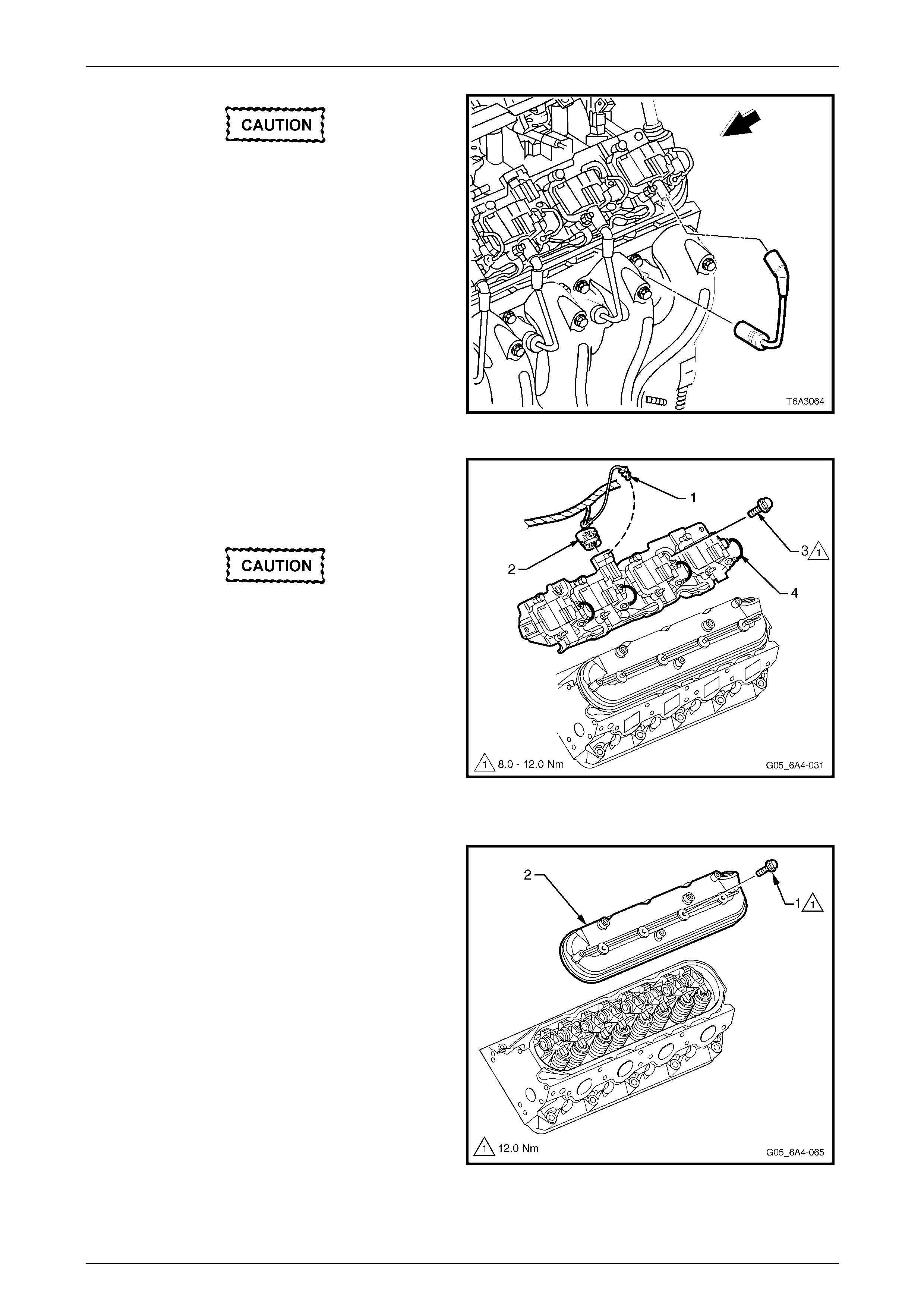
11 Remove the bolt, four and one fastener (3) attaching
the ignition coil mounting bracket (4) to the cover
being removed.
12 Lift the ignition coils, wiring and bracket from the
engine.
Figure 6A4 – 45
13 Remove the bolt (1), four places, then remove the
cover (2) and gasket from the cylinder head.
Figure 6A4 – 46
Engine Mechanical – HSV – Gen IV V8 Page 6A4–29
Page 6A4–29
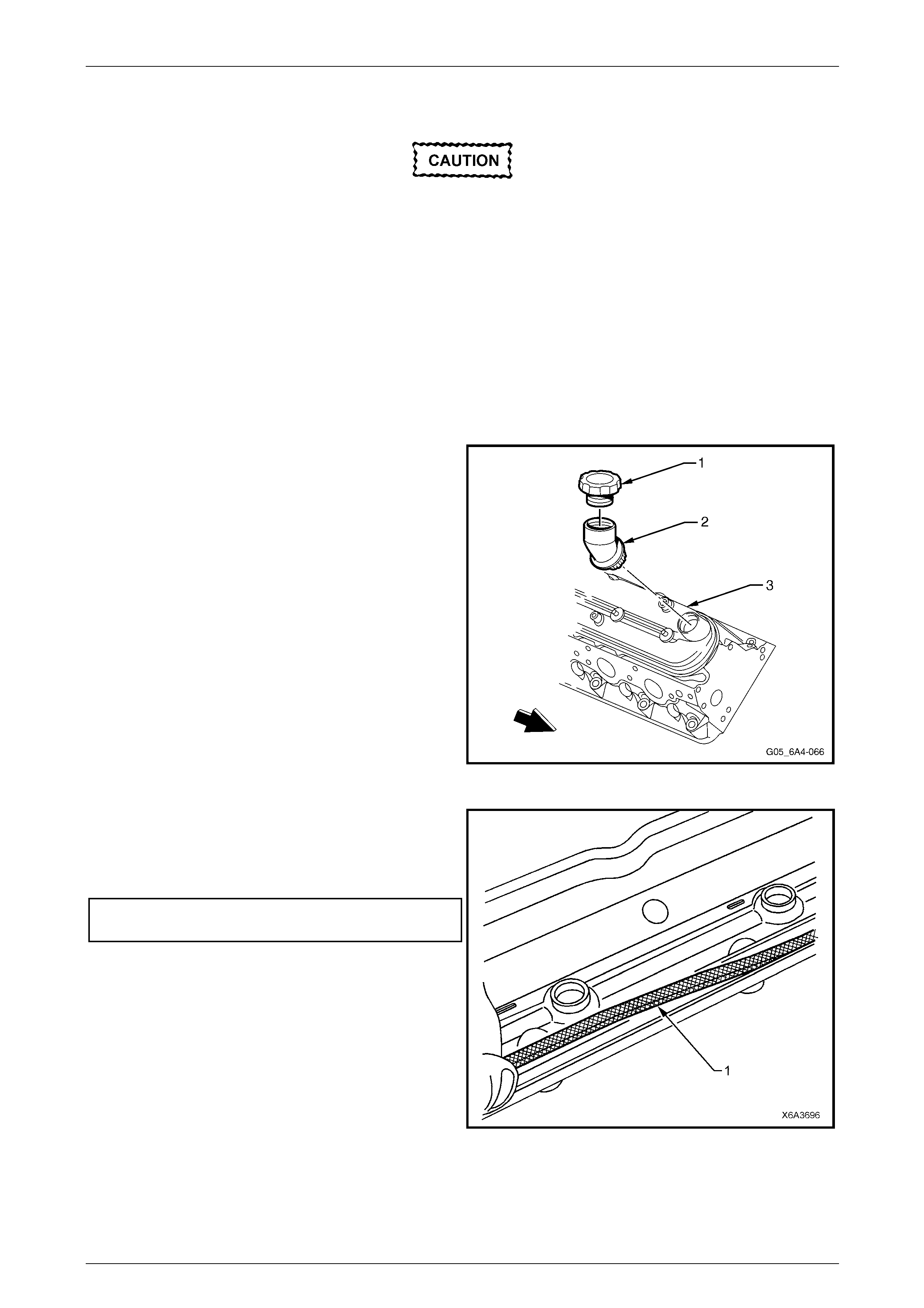
14 Remove the gasket (1) from the cover and discard.
NOTE
The attaching bolt grommets may be re-used if
not damaged.
Figure 6A4 – 47
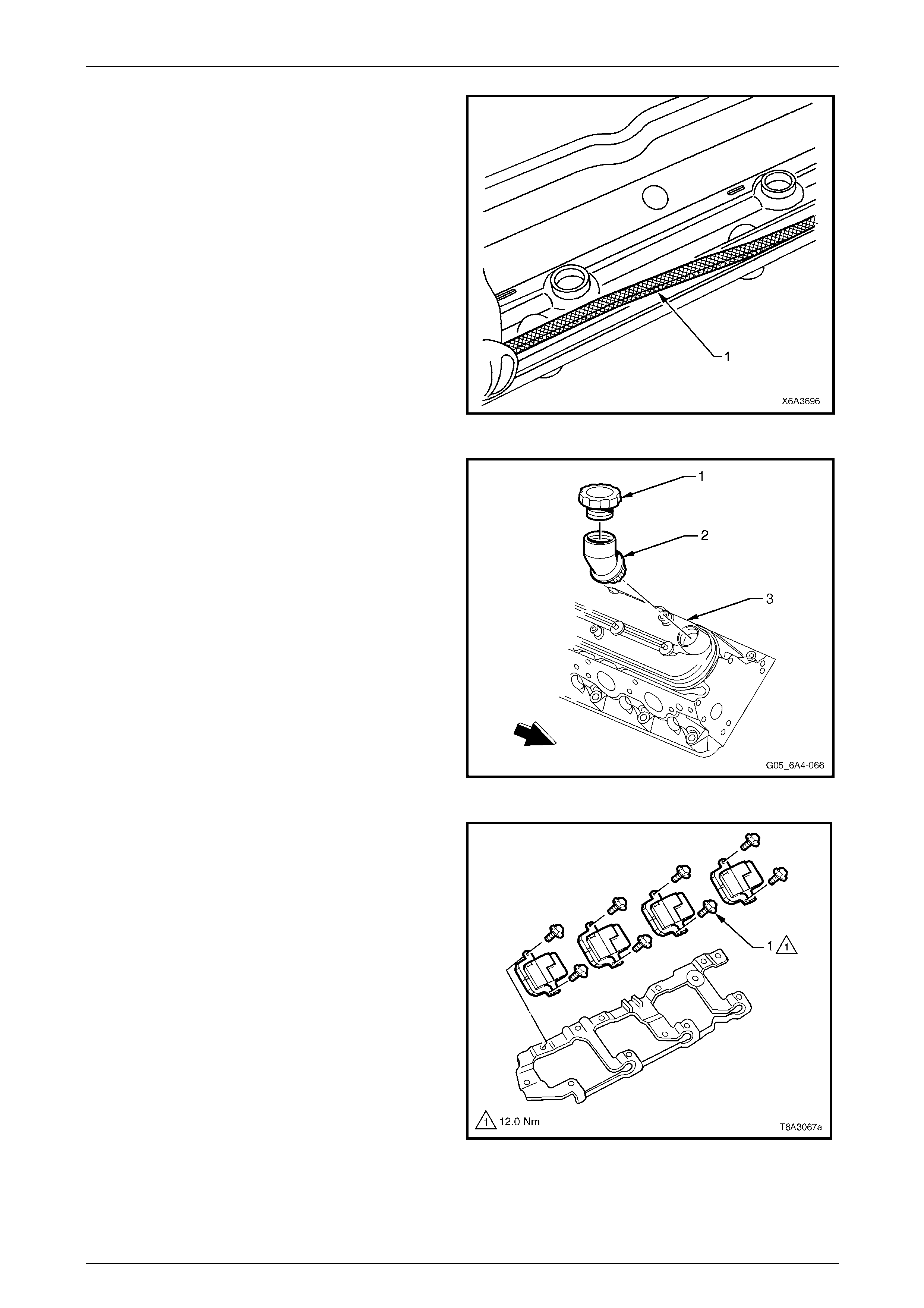
15 If required, remove the oil fill cap (1) and/or fil l tube (2)
from the right-hand valve rocker arm cover (3).
Discard the oil fill tube, as it will have permanent
damage when it is removed.
Figure 6A4 – 48
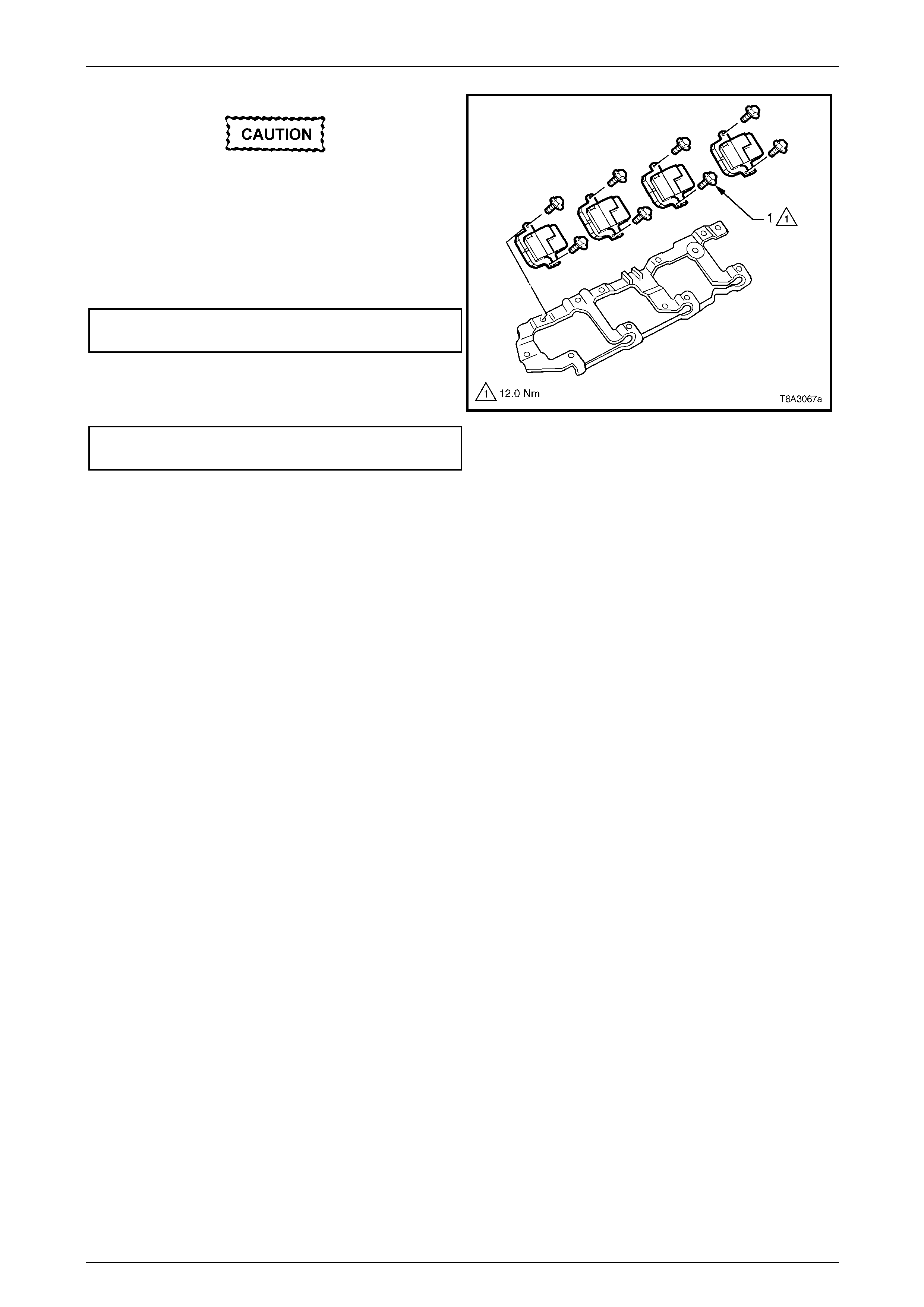
16 If required, remove the eight bolts (1) attaching the
ignition coils to the mounting bracket and remove the
coils.
Figure 6A4 – 49
Engine Mechanical – HSV – Gen IV V8 Page 6A4–30
Page 6A4–30
Clean and Inspect
Wear the appropriate safety glasses and
gloves when using compressed air and
cleaning fluids to avoid eye and skin injury.
1 Clean the valve rocker arm cover in a commercially available cleaning fluid and dry using compressed air.
2 Inspect the ventilation system passages for restriction, clean as require d.
3 Inspect the cover gasket groove for damage.
4 Inspect the ignition coil mounting boss threads for damage.
Reinstall
Reinstallation of the valve roc k er arm cover is the reverse of the removal procedure noting the following items.
1 If the oil fill tube (2) was removed from the right-hand
rocker cover, it must be replaced with a new part.
2 Lubricate the O-ring seal of the new oil fill tube with
clean engine oil.
3 Install the oil fill tube into the cover rotating the tube
clockwise until it is locked into the correct position.
4 Install the oil fill cap (1) rotating clockwise until it is
locked into place.
NOTE
Do not remove the oil fill tube from the right hand
cover unless replacement is required. The oil fill
tube will be damaged in the removal process
and must be replaced.
Figure 6A4 – 50
5 Install a new gasket (1) to the rocker cover.
6 Reinstall the rocker cover onto the cylinder head and
tighten the rocker cover attaching bolts to the correct
torque specification.
Valve rocker arm cover attaching bolt
torque specification............................................12.0 Nm
Figure 6A4 – 51
Engine Mechanical – HSV – Gen IV V8 Page 6A4–31
Page 6A4–31
The left-hand, rear coil mounting bracket
fastener is a plain screw and not a stepped
stud as are the others. Fitment of this screw
in the correct position is important to avoid
fuel/vapour line chaffing.
7 Install the ignition coils onto the mounting bracket and
tighten the bolts (1) to the correct torque specification.
Ignition coil to mounting bracket bolts
torque specification............................................12.0 Nm
8 Install the ignition coil and mounting bracket assembly
to the rocker cover. Tighten the stud and screws to the
correct torque specification.
Ignition coil mounting bracket fastener
torque specification...................................8.0 – 12.0 Nm
9 Install the ignition coil main wiring harness connector
then install the CPA lock ensuring it is fitted securely.
Figure 6A4 – 52
Engine Mechanical – HSV – Gen IV V8 Page 6A4–32
Page 6A4–32
2.5 Cylinder Head Assembly
Remove
Disconnection of the battery affects certain
vehicle electronic systems. Refer to
Section 00, 5 Battery Disconnection
Procedures in the MY 200 4 Holden VZ Service
Information before disconnecting the battery.
1 Disconnect the negative battery cable terminal from the battery.
2 Remove the engine accessory drive belt.
3 Remove the intake manifold. Refer to 2.2 Intake Manifold.
4 Remove the vapour vent pipe. Refer to Section 6A3 Engine Mechanical – 3.8 Vapour Vent Pipe and Covers in the
MY 2004 Holden VZ Service Information.
5 Remove the valve rocker arm cover for the cylinder head that is to be removed.
Refer to 2.4 Valve Rocker Arm Cover.
6 Remove the valve rocker arms and pus h rods on the cylinder head that is to be removed.
Refer to Section 6A3 Engine Mechanical - 3.12 Valve Rock er Arms and Push Rods in the MY 2004 Holden VZ
Service Information.
7 Remove the spark plugs from the cylinder he ad that is to be removed.
8 Remove the exhaust manifold from the cylinder head that is to be removed.
Refer to Section 6A3 Engine Mechanical – 3.14 Exhaust M anifold in the MY 2004 Holden VZ Service Information.
9 For the right-hand cylinder head:
a If fitted with an automatic transmission, remove
the bolt attaching the automatic transmission
dipstick tube bracket bolt (1) from the rear of the
cylinder head.
b Remove the engine oil level indicator and tube.
Refer to Section 6A3 Engine Mechanical -
3.5 Oil Level Indicator and Tube in the MY 2 004
Holden VZ Service Information.
Figure 6A4 – 53
Engine Mechanical – HSV – Gen IV V8 Page 6A4–33
Page 6A4–33
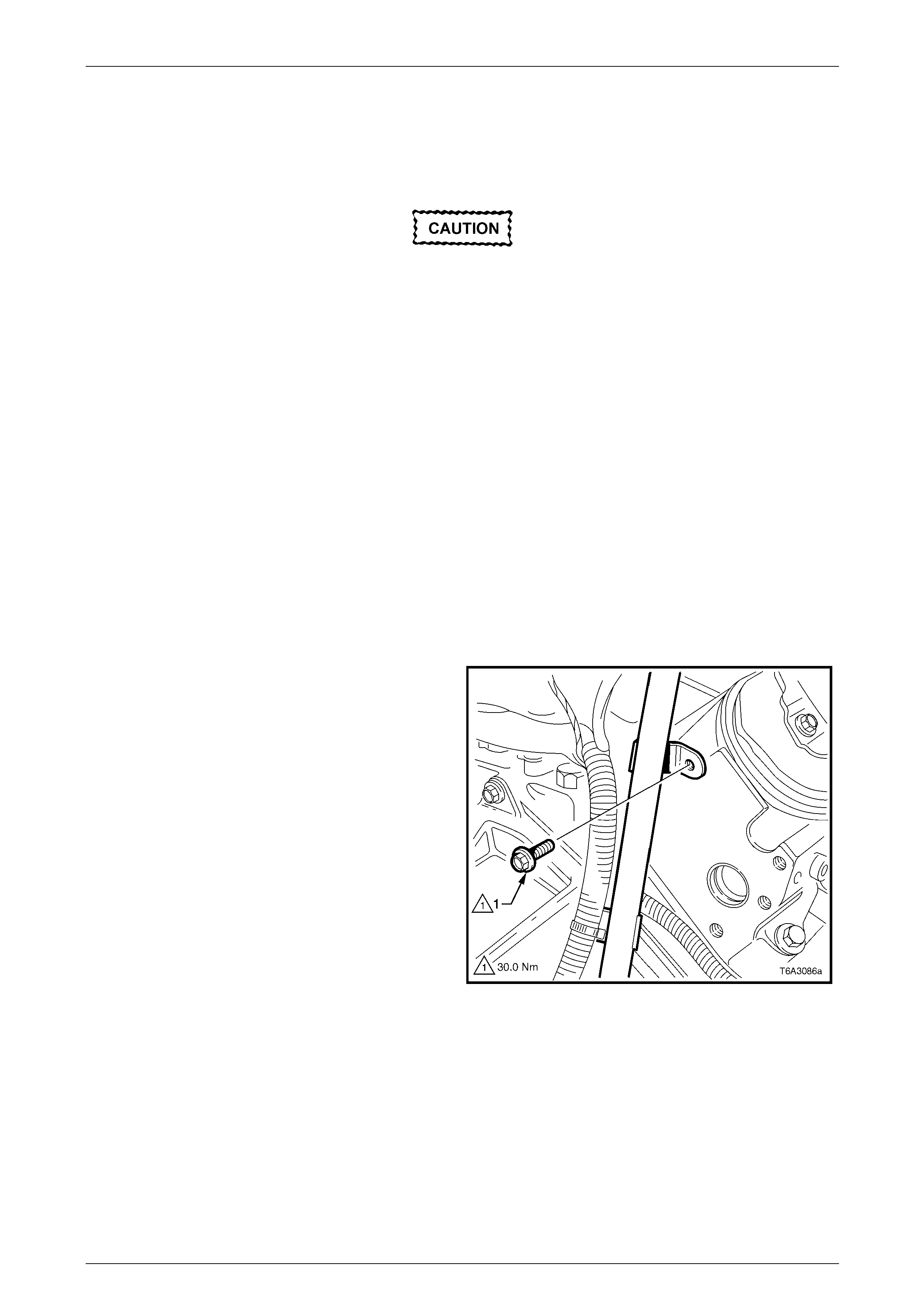
c Remove the bolt (1) attaching the powertrain
harness ground strap to the front of the cylinder
head.
Figure 6A4 – 54
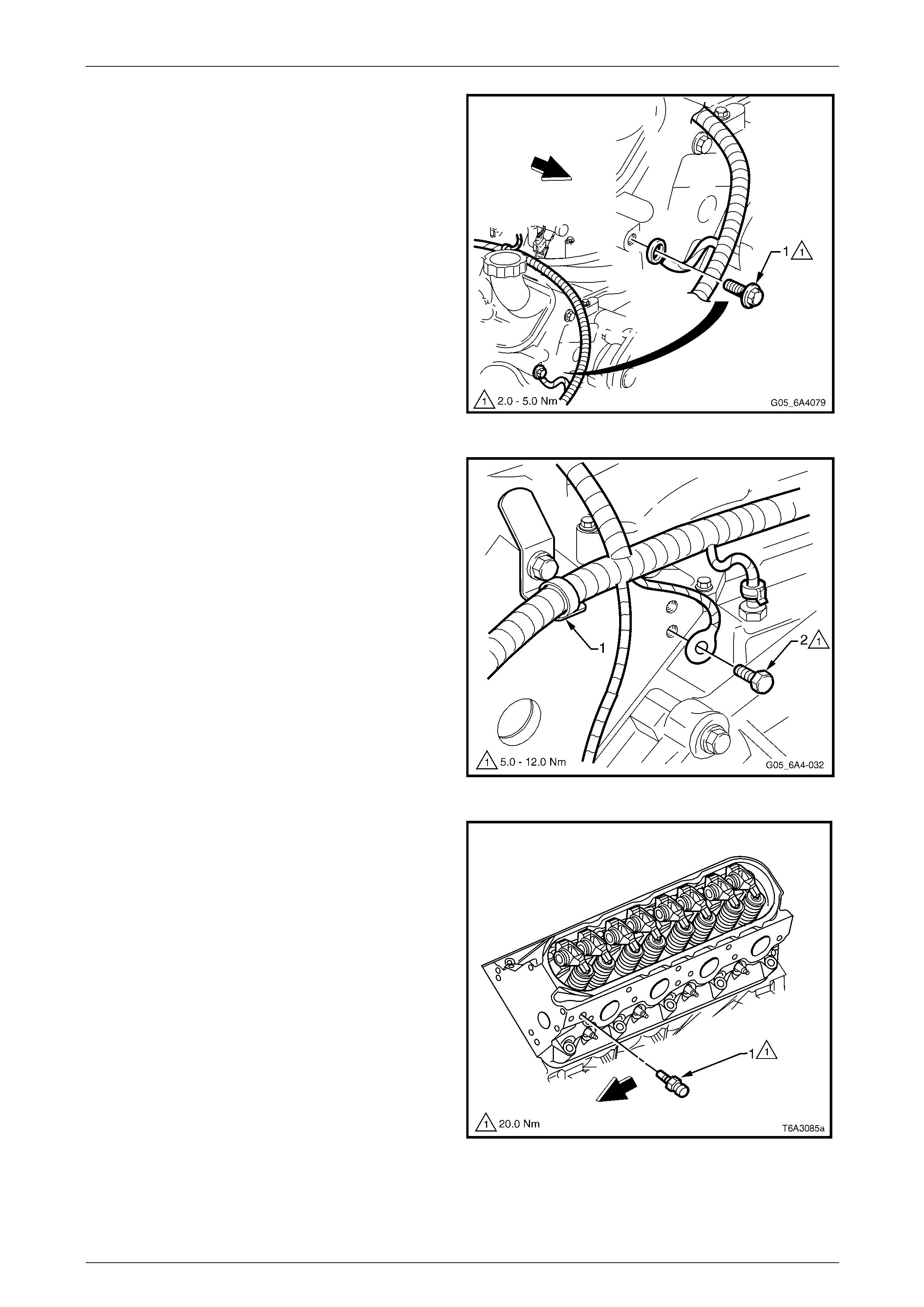
10 For the left-hand cylinder head:
a Remove the powertrain wiring harn ess strap (1)
from the bracket at the rear of the cylinder head.
b Remove the bolt (2) attaching the powertrain
harness ground cable at the rear of the cylinder
head.
c Remove the power steering pump and adapter
block. Refer to Section 9 Steering.
Figure 6A4 – 55
d Remove the coolant temperature sensor (1) from
the front of the cylinder head.
NOTE
This step is necessary to allow the lower left
cylinder head bolt to be removed and to avoid
the risk of accidental damage to the sensor.
Figure 6A4 – 56
Engine Mechanical – HSV – Gen IV V8 Page 6A4–34
Page 6A4–34
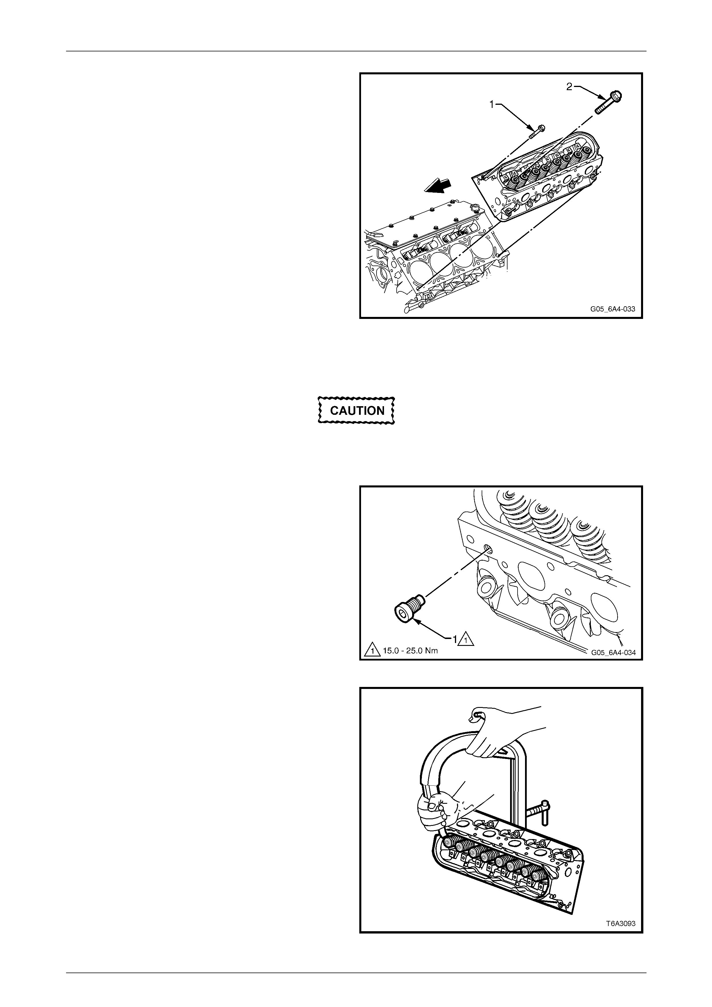
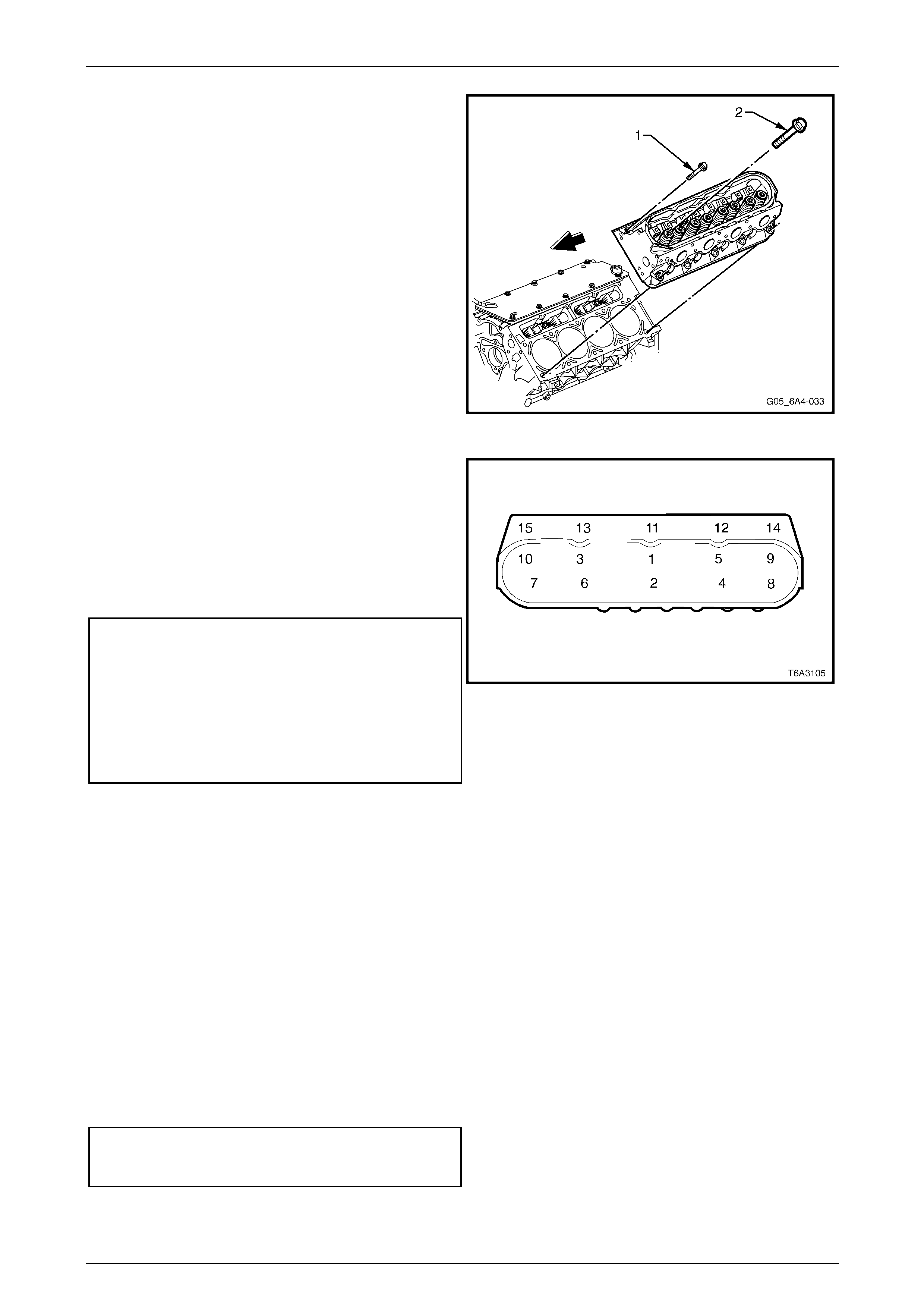
11 Progressively loosen the cylin der head bolts starting
with the M8 bolts (1) first, then the M11 bolts (2)
working from the outside to the centre.
12 Remove the cylinder head from the cylinder block and
place on two blocks of wood to avoid scratching the
machined surface.
NOTE
Discard all M11 bolts (2) after removal as these
are torque to yield bolts. The M8 bolts (1) ca n be
re-used.
13 Remove and discard the c ylinder head gasket.
Figure 6A4 – 57
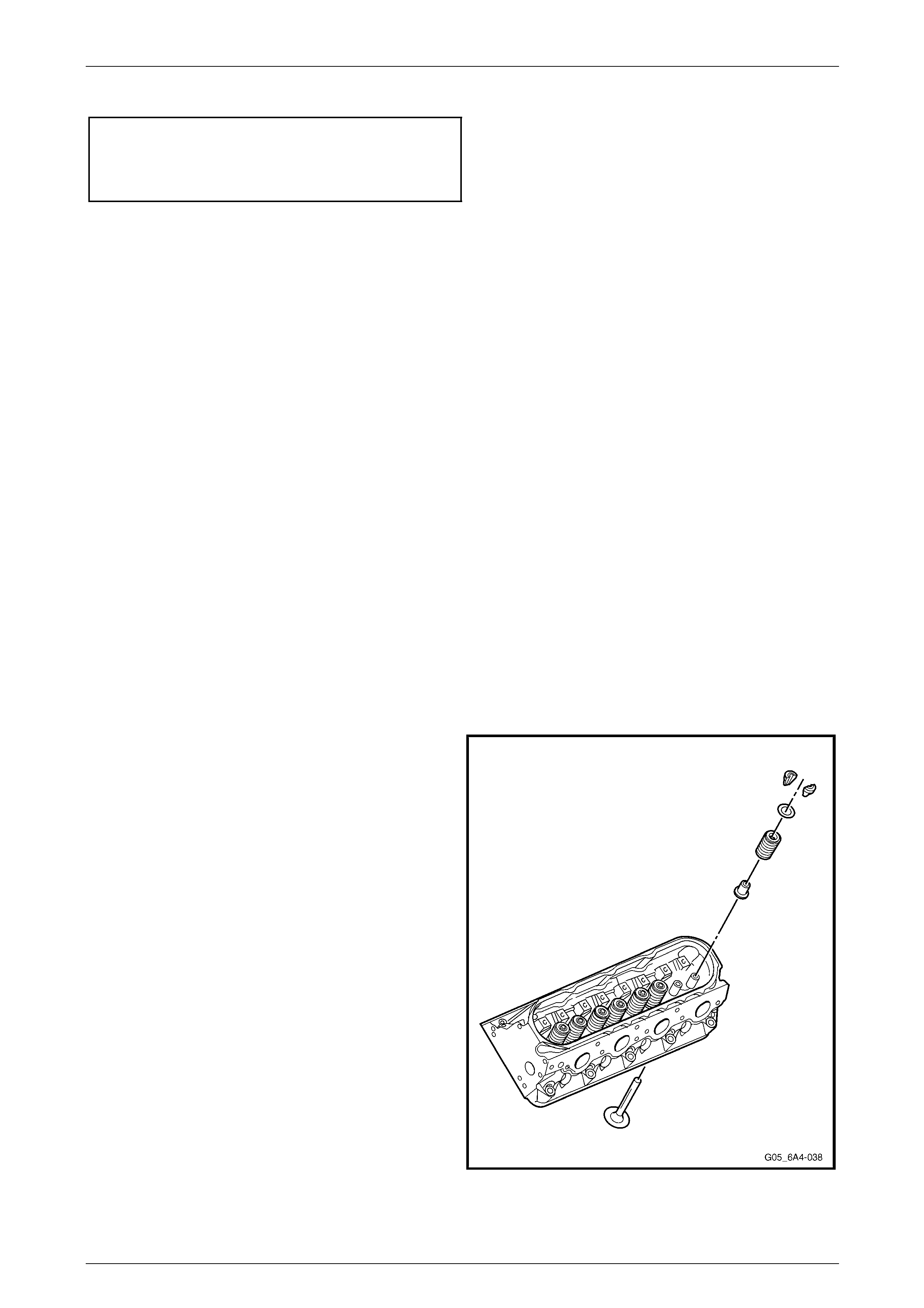
Disassemble
Arrange all valvetrain components in the
order they are removed to ensure they are
reinstalled to their original locations.
1 If required, remove the core plug (1) from the right-
hand cylinder head.
NOTE
The core plug must not be reused. If the plug is
loosened, it must be replaced wit h a new one.
Figure 6A4 – 58
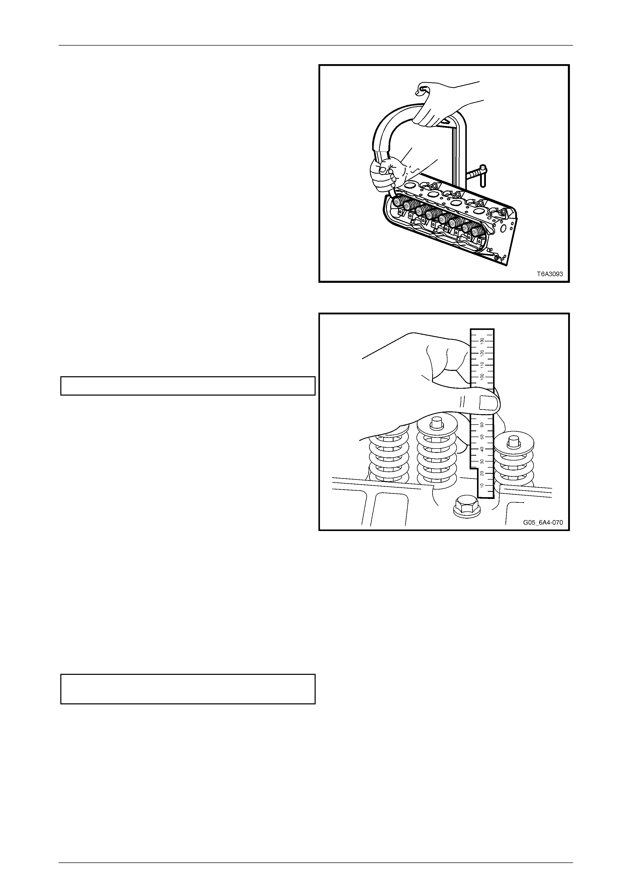
2 Compress the valve spring using a valve spring
compressor.
NOTE
It may be necessary to tap the valve spring end
of the compressor with a plastic faced hammer
to loosen jammed valve collets.
Figure 6A4 – 59
Engine Mechanical – HSV – Gen IV V8 Page 6A4–35
Page 6A4–35
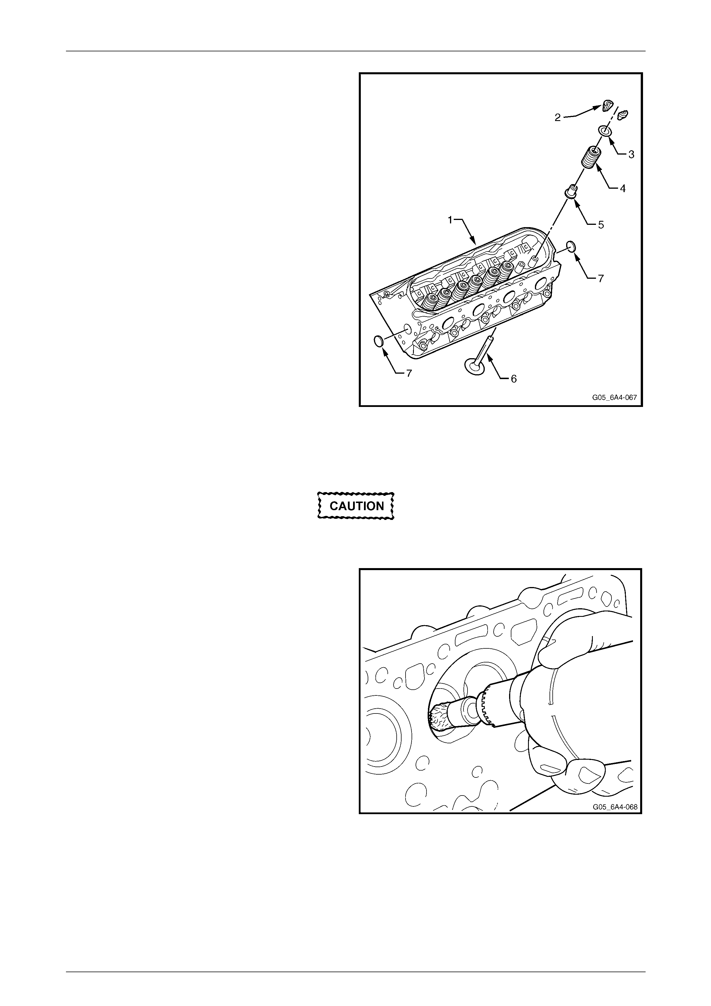
3 Remove the following components from the cylinder
head (1):
a Valve stem collets (2), 2 places.
b Valve spring cap (3).
c Valve spring (4).
d Valve stem oil seal and shim assembly (5).
e Valves (6).
4 Repeat for the remaining valves.
NOTE
Do not remove the expansion plugs (7) unless
servicing is required.
Figure 6A4 – 60
Clean and Inspect
Wear safety glasses when using compressed
air to avoid eye injury.
1 Clean all carbon deposits from the combusti on
chambers and valve ports using a commerc ially
available rotary wire brush. Do not scuff or damage
the aluminium cylinder head surfaces.
2 Clean carbon deposits from the valve stems and
heads on a wire buffing wheel.
3 Check all M8 bolts threads for damage and corrosion
and remove all thread lock ing compound from both the
threaded holes and bolts.
NOTE
Replace any M 8 bolts that are damaged or sho w
signs of corrosion. The M11 bolts must be
replaced, as these are torque to yield bolts.
Figure 6A4 – 61
Engine Mechanical – HSV – Gen IV V8 Page 6A4–36
Page 6A4–36
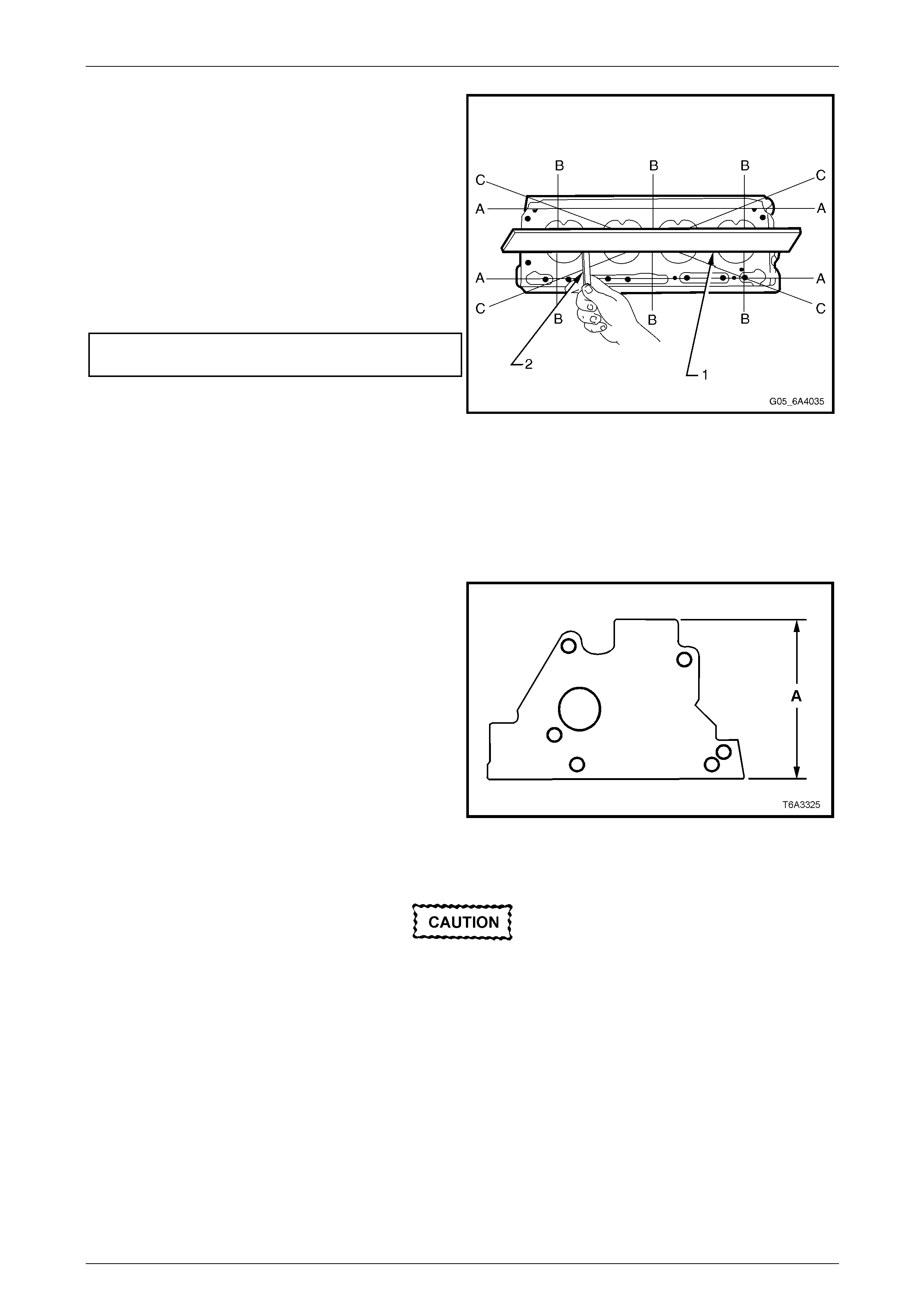
4 Check the cylinder head surface for distortio n and
flatness:
• deck surface
• inlet manifold surface
• exhaust manifold surface
Use a straight edge and feeler gauges, checking each
surface lengthwise (A), crosswise (B) and diagonally (C).
5 Check the cylinder head deck to exhaust manifold
mating surface and the cylinder head deck to intake
manifold surface for flatness.
Cylinder Head Flatness
Specification...................................................... 0.22 mm
Figure 6A4 – 62
NOTE
If any of these surfaces are outside specification,
the cylinder head ma y be machined, prov ided the
minimum overall height of 120.2 mm (A) is not
exceeded. Refer to Figure 6A4 – 63.
6 Inspect all threaded holes for damage and repair as
required with suitable thread inserts.
Refer to Section 6A3 Engine Mechanical -
5 Thread Repair in the MY 2004 Holden VZ Service
Information.
7 Clean any cylinder head bolt thread sealant residue
from the cylinder block threads using installe r T ool No.
J-42385-107 (this tool is part of the thread re pair kit
Tool No. J-42385), refer to Section 6A3 Engi ne
Mechanical - 8 Special Tools in the MY 2004 Holden
VZ Service Information.
NOTE
Do not use anything but the correct threa d repair
tool to clean the cylinder head threads in the
cylinder block. Figure 6A4 – 63
Wear safety glasses when using compressed
air to avoid eye injury.
8 Use compressed air to clean all residue from the bolt holes.
9 Inspect the coolant jacket expansion plugs for signs of corrosion. Replace plugs as necessary.
NOTE
If replacing the expansion plugs, apply a coating
of Loctite 242 or equivalent around the plug
sealing surface.
10 Inspect the cylinder head for cracks, especially between valve seats or exhaust ports.
11 Inspect the cylinder block deck surface for di stortion, refer to Section 6 A3 Engine Mechanical - 4.15 Cylinder Block
in the MY 2004 Holden VZ Service Information.
Engine Mechanical – HSV – Gen IV V8 Page 6A4–37
Page 6A4–37
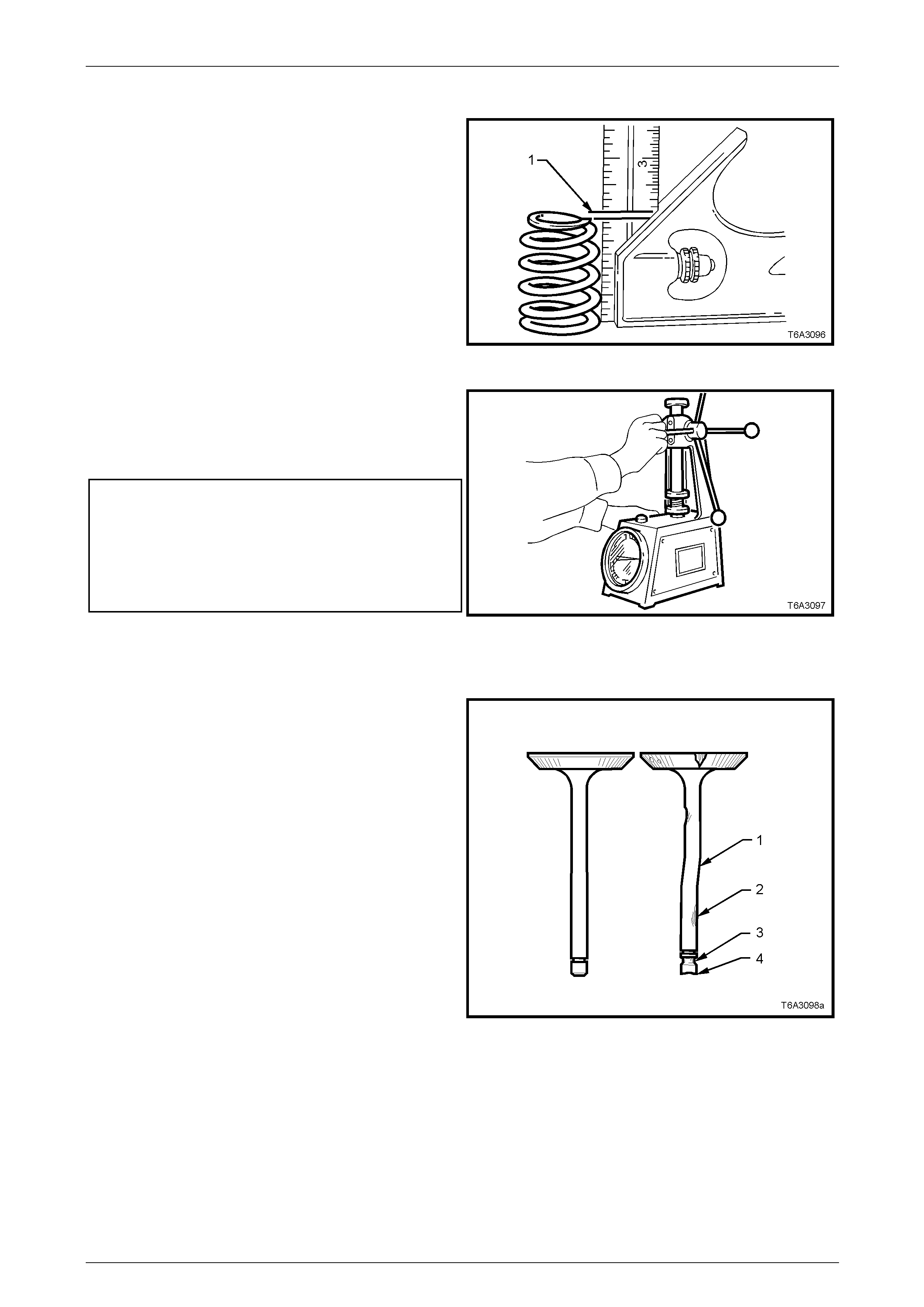
Valve Springs
1 Check all the valve springs for distortion. There should
be no more than 1.6 mm variance (distance 1) of the
spring end while the spring is being rotated on a flat
surface. Replace any springs that exceed this
specification.
Figure 6A4 – 64
2 Use a commercially available valve spring tester to
measure each valve spring free height and tension.
3 Discard any spring that does not conform to the
specification.
Valve Spring Specifications
Free height
(Intake and Exhaust.......................................... 52.9 mm
Tension Specificatio n
(Closed valve, minimum....................310 N at 45.75 mm
(Open valve, minimum......................980 N at 33.55 mm
Figure 6A4 – 65
Valves
1 Inspect the valve stems for burrs and scratches. If
minor, these can be removed with a crocus cloth.
2 Inspect the valves for the following:
• Valves that are warped (1) or have excessive
stem wear (2), should be replaced.
• Inspect the valve stem collet groove (3) for wear
or damage and replace if required..
• Inspect the valve stem end (4) for wear. If
required minor wear can be corrected by
grinding, provided the stem end is ground at
right angles to the valve stem.
Figure 6A4 – 66
Engine Mechanical – HSV – Gen IV V8 Page 6A4–38
Page 6A4–38
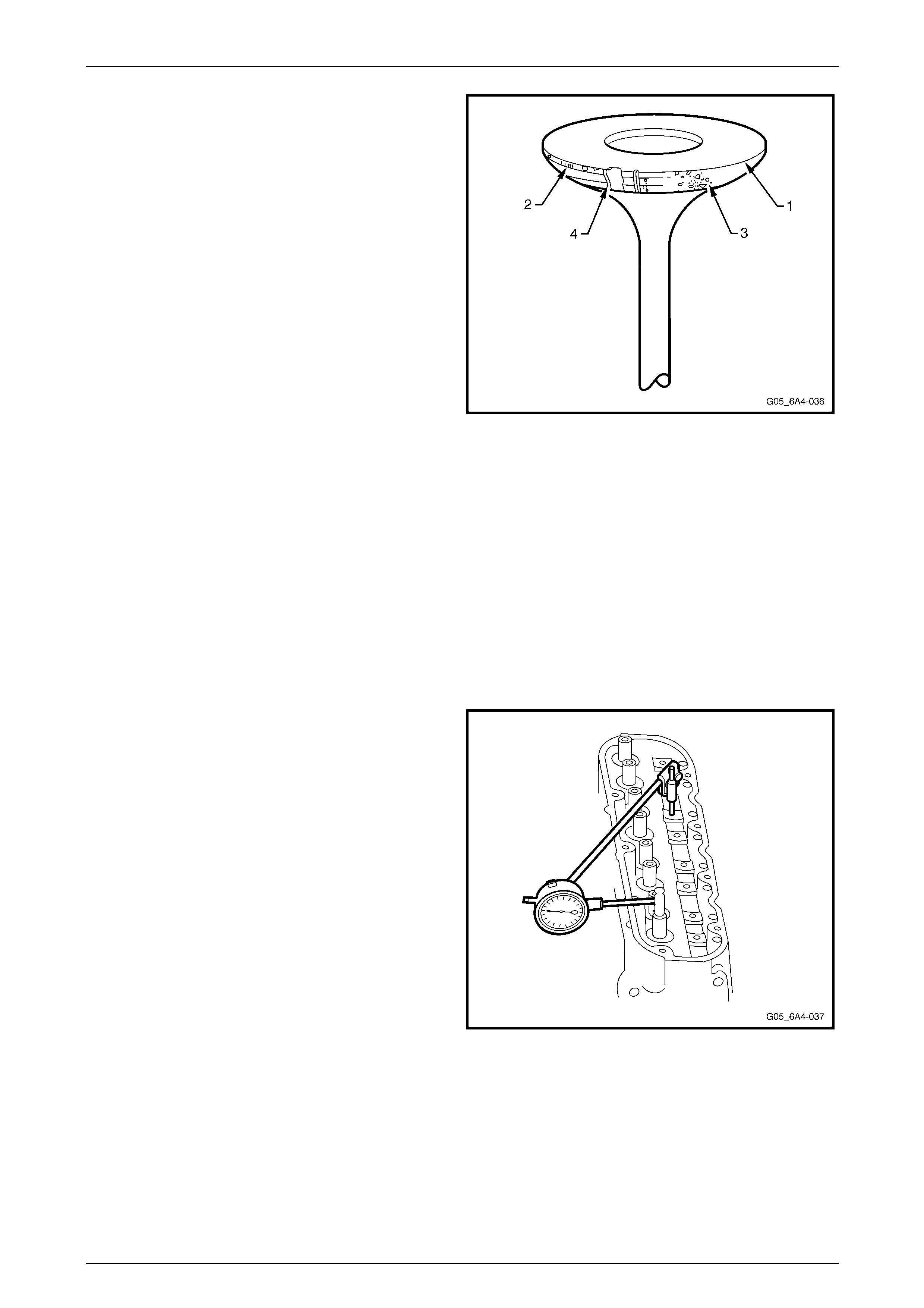
3 Check the valve face for the following:
• Margin (1) for less than 1.25 mm after
grinding the seating surface (2), resurface or
replace as required.
• Excessive pitting (3), resurface or replace as
required.
• Burnt or corroded areas (4), resurface or replace
as required.
4 Measure the valve stem diam eter. A valve stem with a
diameter of less than 7.95 mm must be replaced.
5 If an exhaust valve is to be reconditioned, the face can
be ground, using a valve refacing machine.
6 Before grinding the valves, observe the foll owing:
a Follow the valve reconditioni ng equipment
manufacturers recommendations to ensure the
required standard of finish is achieved.
b If an exhaust valve face is reground, it may be
necessary to shim the valve spring to achieve
the correct spring installed height.
Refer to 2.5 Cylinder Head.
NOTE
Intake valve faces must not be refaced. Intake
valves that are worn or have face damage must
be replaced.
Figure 6A4 – 67
Valve Guides
Excessive valve stem to guide clearance may cause a noisy valve train, prematur e valve stem oil seal wear, component
damage and/or excessive oil consumption.
Insufficient valve stem to guide clearance will result in noisy or sticking valves. Valves that are too tight may disturb
engine smoothness or lead to compon ent damage.
Measure the clearance as outlined in the following steps.
1 Insert the valve into its guide.
2 Clamp a dial indicator onto a valve rocker arm bolt that
has been temporarily instal led. Place the dial gauge in
a position where sideways movement of the valve
stem will cause movement of the indicator needl e.
a To obtain a correct indication of the wear, the
indicator stem must contact the side of the valve
stem, between 8 – 12 mm above the top of valve
guide and the gauge is to be at right-angles to
the valve stem.
3 With the valve head dropped by approximately 2 mm
off its seat, move the stem of the valve side to side
against the dial indicator usin g light force, to obtain a
clearance reading.
a This may need to be done in two directions,
fore/aft and side to side, which will require the
dial indicator to be repositioned.
NOTE
If the valve stem diameter is within specifica tions
and the valve stem to guide clearance exceeds
0.093 mm (either intake or exhaust), the
clearance must be corrected, refer to
Oversize Valve Stem or the valve gui de must be
replaced.
Figure 6A4 – 68
Engine Mechanical – HSV – Gen IV V8 Page 6A4–39
Page 6A4–39
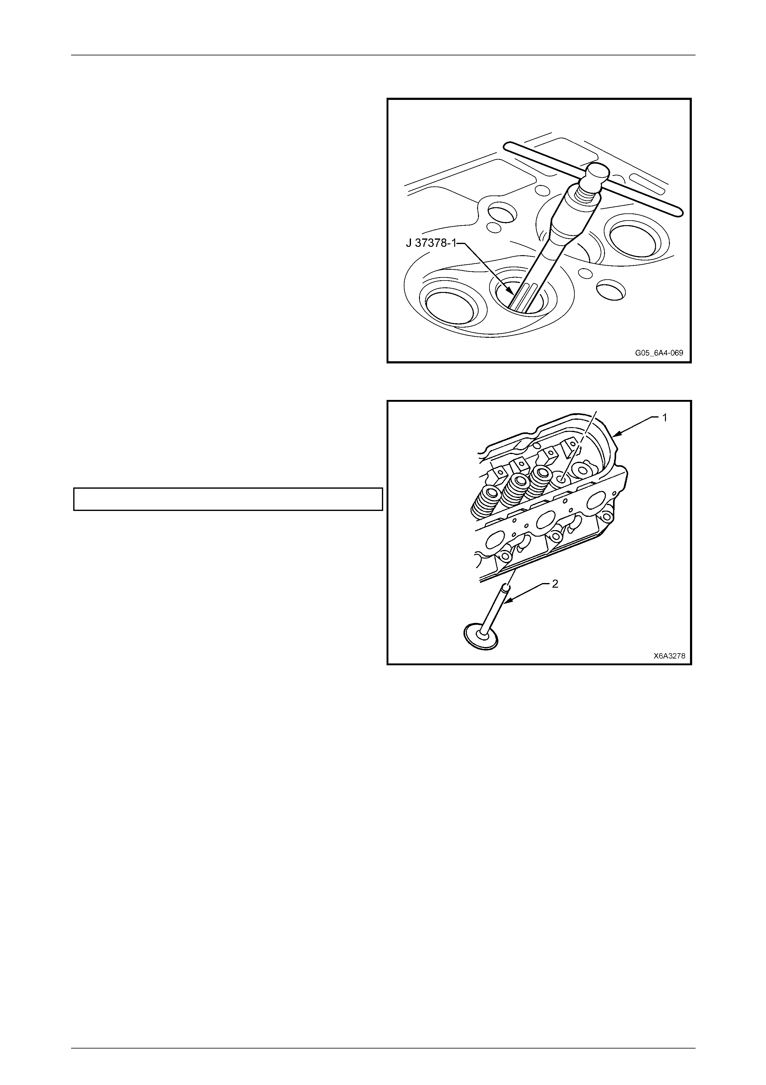
Oversize Valve Stem
1 Ream the valve guide using Tool No. J 37378-1.
2 Clean the valve guide bore of all metal shavings and
debris.
Figure 6A4 – 69
3 Install the oversize valve (2) into the ream ed valve
guide and recheck the valve guide clearance.
4 The valve should slide freely without resistance or
drag and the clearance must not exceed the
specification.
Valve stem to guide clearance........................0.093 mm
Figure 6A4 – 70
Valve Seats
Check the valve seats for any evidence of pitting or damage at the valve contact surface. If pitting is evident, the valve
seats will need to be reconditioned.
Correct reconditioning of the valve seats is very important because the seating of the valves must be precise for the
engine to deliver the po wer and performance specified. Another important factor is the cooling of the val ve head. Good
contact between the valve and its seat in the head is imper ative to ensure that heat in the valve head will be transferred
efficiently.
Several different types of equipment are av ailable for reconditioning valve seats, with an oscillatin g type valve seat
grinder being preferred. The recommendations of the manufacturer of the equipment being used should be carefully
followed to attain optimum results.
NOTE
Since the valve guide serves to support and
centre the valve seat grinder, it is essential that
the valve guide be checked for wear, refer to
Valve Guides in this Section.
Engine Mechanical – HSV – Gen IV V8 Page 6A4–40
Page 6A4–40
Both the intake and exhaust valve se at angles are 46 Degrees and the seat width should not exceed the specification.
Valve seat width specification:
Intake................................................1.02 mm maximum
Exhaust.............................................1.78 mm maximum
If valve seats are reconditioned and the exhaust valve faces ground, then light lapping will ensure a gas tight seal when
closed.
NOTE
New valves must not be lapped, as this will
destroy the protective coating on the valve face.
After refacing an existing valve or installing a new valve, correct seating of the valve must be checked as follows:
a Lightly coat the valve face with bearing (Pru ssian) blue.
b Insert the valve and rotate approximately 60 Degrees.
c Remove the valve and check its contact with the seat.
d If full contact is indicated, the valve and seat are acceptable.
e However, if only partial contact is shown, reinstall the valve and rotate it for one full turn. If blue now indicates a full
contact, then the valve must be refaced or replaced. If the blu e contact sti ll only shows partial contact then regrind
the valve seat.
f Clean all traces of blue from the valves and seats and then clean thoroughly before applying clean engine oil to
both surfaces to protect from rusting.
Reassemble
NOTE
Ensure that all re-used valve train components
are reinstalled to their original locations.
1 Lubricate all valve stems, guides and valve faces with
clean engine oil, then install th e valves to their correct
ports.
2 Install a new valve stem oil seal and shim assembly by
hand, until the shim seats against the cylinder head.
No special tools are required for this operation.
NOTE
The valve stem oil seal alignment and position
on the valve stem is critical. An improperly
installed valve stem oil seal will lead to excessive
oil consumption and increased exhaust
emissions.
Figure 6A4 – 71
Engine Mechanical – HSV – Gen IV V8 Page 6A4–41
Page 6A4–41
3 Install the valve spring and cap to the valve stem.
4 Compress the valve spring using a spring compressor.
5 Install valve stem collets, retaining them with
petroleum jelly if required.
6 Ensure that both the collets are correctly located
before releasing the valve spri ng compressor.
7 Tap the end of the installed va lve stem with a plastic
faced hammer to seat the collets.
Figure 6A4 – 72
8 Measure the valve spring installe d height using a ruler
or vernier calipers. The measurement is to be taken
from the base of the valve spring abov e the valve stem
oil seat/shim combination to the top of the valve
spring.
Valve spring installed height ........................... 46.25 mm
NOTE
If the measurement exceeds 46.25 mm, a
commercially available stainless steel shim must
be installed bet ween the valve stem oil s eal/shim
combination and the cylinder head to achieve
the required spring height.
NOTE
Do not shim the valve spring to obtain less than
the specified height.
9 Install the remaining valves, springs and other valve
train components, checking each valv e spring height
as it is assembled.
10 If the expansion plugs were removed from the cylinder
head, apply sealant such as Loctite 565 or equivalent
to the plug before installation.
11 Install a new core plug (1) to the right-hand c ylinder
head and tighten to the correct torque specification,
refer to Figure 6A4 – 58.
Cylinder head core plug
torque specification.................................15.0 – 25.0 Nm
Figure 6A4 – 73
Engine Mechanical – HSV – Gen IV V8 Page 6A4–42
Page 6A4–42
Reinstall
Reinstallation of either or both cylinder heads is the reverse to the removal procedure, noting the follo wing:
Do not reuse the M11 cylinder head bolts.
Only use new M11 bolts when installing a
cylinder head. Do not use any sealant on the
cylinder head gasket or thread lock
compound on the M11 cylinder head bolts.
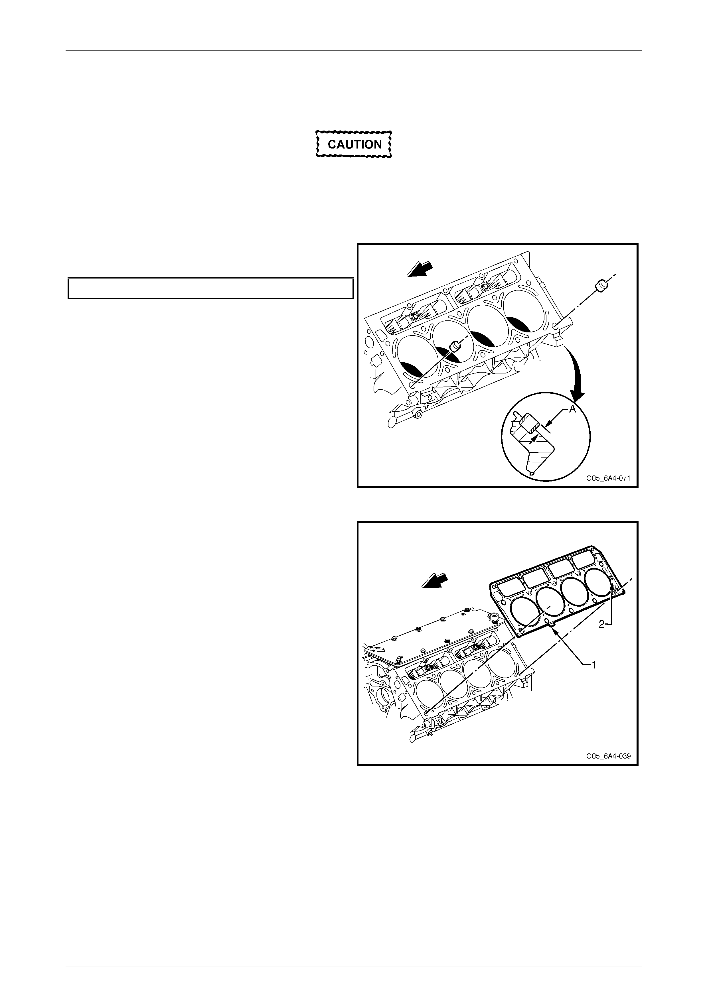
1 Check the cylinder head locati ng sleeves for the
correct installation height at dimension A.
Dimension (A) Maximum.................................... 8.3 mm.
Figure 6A4 – 74
2 Ensure the cylinder head and block are clean from oil
and other contaminants. Do not use an y sealers on
the gasket surface.
3 Install a new cylinder head gasket correctly over the
locating sleeves.
NOTE
The tab (1) on the cylinder head gasket is
located to the front half point. This applies with
either cylinder head gasket. The cylinder head
gaskets will fit on either side of the engine. The
only condition is that the word FRONT stamped
on the gasket must face the engine front. The
gasket should also have 6.0 (2) imprinted on it.
Figure 6A4 – 75
Engine Mechanical – HSV – Gen IV V8 Page 6A4–43
Page 6A4–43
4 Carefully install the c ylinder he ad over the locating
sleeves and the previously installed gasket.
5 Apply a 5 mm band of thread lock such as Loctite 242
only to the threads of the M8 bolts (1).
NOTE
Do not apply thread lock to the M11 bolts.
6 Install the M8 cylinder head bolts then loosely install
the new M11 bolts (2).
Figure 6A4 – 76
7 Tighten the cylinder head bolts in the sequence shown
and to the correct torque specification.
NOTE
Use a torque angle meter such as Tool No.
E 7115 to achieve an accurate turn angle
reading. Bolt numbers 1 to 10 are the M11 bolts
while bolts 11 to 15 are the M8 bolts.
Cylinder head bolt torque specification:
M8 bolts .............................................................30.0 Nm
M11 bolts
Stage 1 ..............................................................30.0 Nm
Stage 2 .....................................................90° turn angle
Stage 3
Bolts 1 to 8................................................90° turn angle
Bolts 9 and 10 only ...................................50° turn angle
Figure 6A4 – 77
8 For the remainder of reinstallation process, refer to the following procedures in the order listed:
a Section 6A3 Engine Mech anical – 3.12 Valve Rocker Arms and Push Rods in the MY 2004 Holden VZ
Service Information.
b 2.4 Valve Rocker Arm Cover.
c Section 6A3 Engine Mech anical – 3.8 Vapour Vent Pipe and Covers in the MY 2004 Holden VZ Service
Information.
d 2.2 Intake Manifold.
e Section 6A3 Engine Mech anical – 3.14 Exhaust Manifold/s in the MY 2004 Holden VZ Service Information.
f Section 6A3 Engine Mechanical – 3.5 Oil Level Indicator and Tube in the MY 2004 Holden VZ Service
Information.
NOTE
If the cylinder head is replaced, the initial spark plug torque specification must be amended to the following
specifications.
Spark plug torque specification
Used cylinder head............................................15.0 Nm
New cylinder head .............................................20.0 Nm
Engine Mechanical – HSV – Gen IV V8 Page 6A4–44
Page 6A4–44
2.6 Engine Dress Cover
Remove
1 Remove the strut tower brace (1).
Refer to Section 1A1 Body.
2 Disengage the engine dress cover ball studs (2) by
pulling upward.
3 Raise the cover to unlock it from the fuel rail (3) and
remove the cover.
NOTE
Rubber grommets are used to locate the cover
to the ball studs. These may be retained on the
ball stud when the cover is removed.
4 If required, remove the rubber grommets (4) from the
ball studs and reinstall the grommets to the cover prior
to reinstalling the cover.
A
A
1
2
3
2
3
SEC A
Figure 6A4 – 78
Reinstall
Reinstallation of the valve roc k er covers is the reverse of the removal procedure ensuring the retaining clips are fully
attached.
Engine Mechanical – HSV – Gen IV V8 Page 6A4–45
Page 6A4–45
3 Major Service Operations
3.1 Engine Assembly
Remove
Disconnection of the battery affects certain
vehicle electronic systems. Refer to
Section 00, 5. Battery Disconnection
Procedures in the MY 200 4 Holden VZ Service
Information before disconnecting the battery.
1 Disconnect the negative battery cable terminal from the battery.
Do not remove the pressure cap from the
radiator while the engine coolant temperature
is above 50° C, as personal injury will most
likely occur.
2 Allow the engine to cool to ambient temperature (less than 50°C), then slowly remove the pressure cap from the
radiator, refer to Section 6B4 Engine Co oling – GEN IV V8.
3 Remove the strut tower brace (1). Refer to Section 1A1 Body in the MY 2004 Holde n VZ Service Information.
4 Remove the fresh air hose (1) from the air intake duct
(2) and lay it to the side of the engine.
5 Remove the air intake sensor wiring harness
connector (3).
6 Loosen the hose clamps attachin g the intake duct to
the air box and the throttle body and remove the duct
from the engine.
7 Remove the duct from the engine.
8 De-pressurise the fuel rail.
Refer to Section 8A1 Fuel System in the MY 2004
Holden VZ Service Information.
9 Refer to Section 6B4 Engine Cooling – GEN IV V8 and
remove the following:
• Radiator fan and shroud assembl y
• Radiator
• Top and lower radiator hos es
12
3
Figure 6A4 – 79
Engine Mechanical – HSV – Gen IV V8 Page 6A4–46
Page 6A4–46
10 Recover the refrigerant charge, Refer to
Section 2C HVAC Climate Control (Manual A/C) –
Removal and Installation.
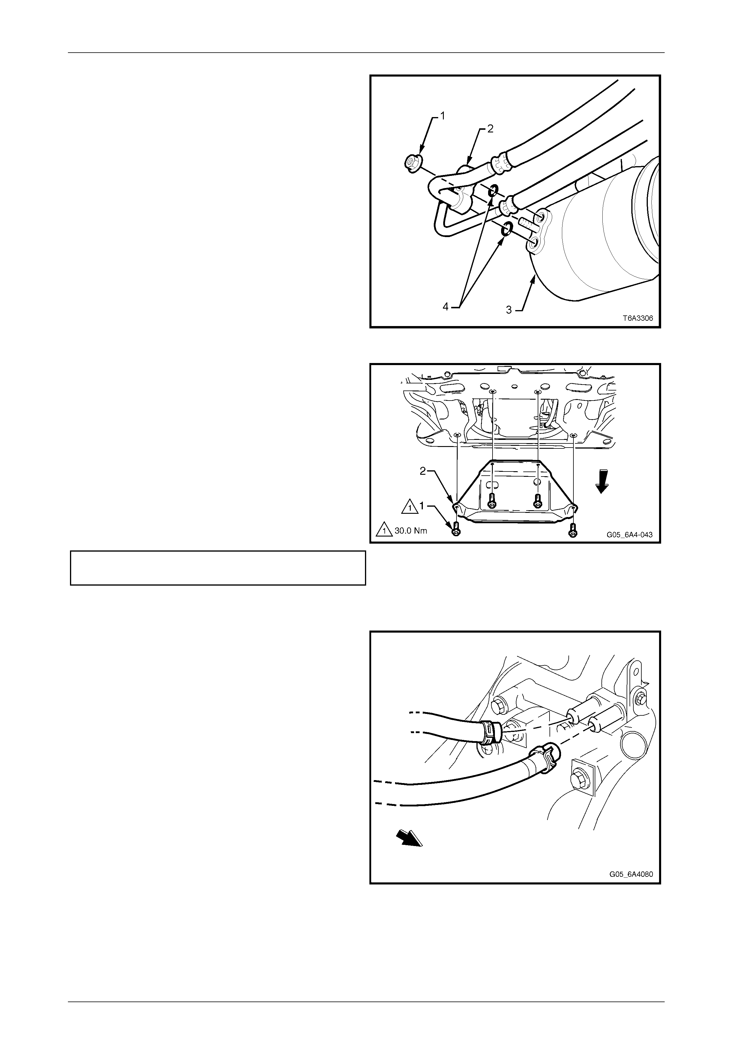
11 Remove the nut (1) attaching the suction/discharg e
hose pad (2) to the air conditioning compressor (3)
then remove the O-rings (4) and immediately cap or
plug all openings to prevent contamination.
Figure 6A4 – 80
12 Remove the four bolts (1) attaching the under-tray (2)
to the crossmember and remove the under-tray from
the vehicle.
13 Drain the engine oil into a suit able container, refer to
Section 6A3 Engine Mechanical -
3.3 Engine Oil and Filter In the MY 2004 Holden VZ
Service Information.
NOTE
Reinstall the drain plug once the oil has drained
sufficiently and tighten the drain plug to the
specified torque.
Oil pan drain plug
torque specification............................................25.0 Nm Figure 6A4 – 81
14 Remove the engine hood, refer to Section 1A4 Hood and Rear Compartment Lid In the MY 2004 Holden VZ
Service Information.
NOTE
Mark the hoses prior to removal with a paint pen
or similar.
15 Remove both heater hose clamps at the engine water
pump, taking note of the hose layout. Plug the open
ends to prevent entry of dirt or other contaminants.
Figure 6A4 – 82
16 Remove the ground lead to the engine cylinder block and from the left hand engine mount, refer to
Section 12O Fuses, Relays and Wiring Harnesses.
17 Remove the positive lead terminal from the battery and lay the harness on the engine.
Engine Mechanical – HSV – Gen IV V8 Page 6A4–47
Page 6A4–47
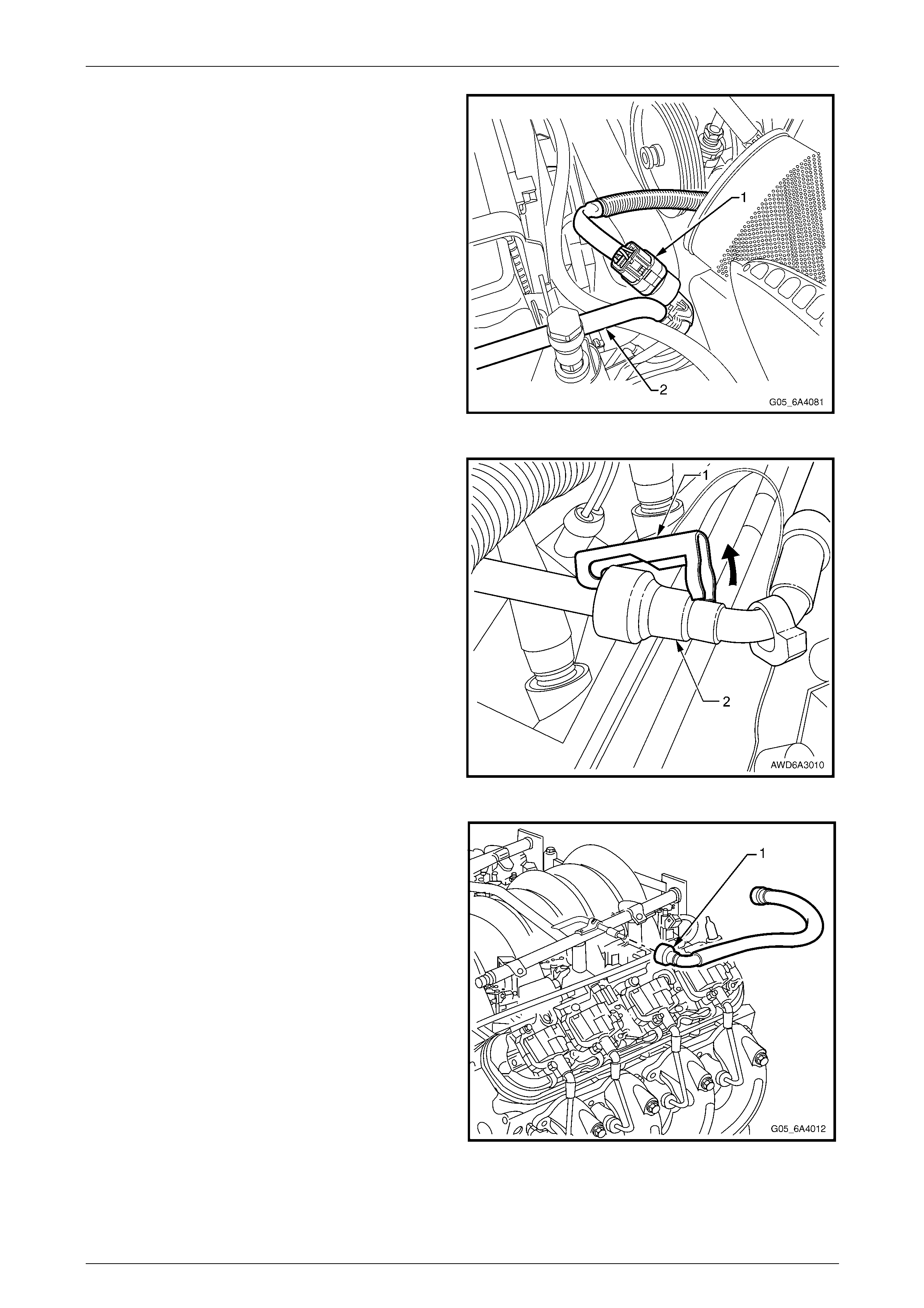
18 Disconnect the air conditioning wiring har ness
connector (1) attached to the air conditioning
condensor pipe (2).
Figure 6A4 – 83
19 Using a small scre wdriver, release the s ecurity lock
(1), at each of the fuel supply hose quick connect
fittings (2).
NOTE
The security lock at the fuel rail side onl y, is fitted
to a tether to prevent loss.
Figure 6A4 – 84
20 Depressurise the fuel system.
21 Install the quick connect release Tool, No. 7371 over
the fuel line. Refer to Section 6C4 Powertrain
Management – GEN IV V8.
22 Close the quick connect release tool and pull it into the
fuel rail line quick connect fitting (1), to release it from
the fuel rail then pull back on the quick conne ct to
disengage. Remove the quick connect release tool
from the fuel rail line.
NOTE
Plug all openin gs to prevent fuel leaking and dirt
from entering the fuel system.
Figure 6A4 – 85
Engine Mechanical – HSV – Gen IV V8 Page 6A4–48
Page 6A4–48
23 Disconnect the EVAP purge valve vapour line (1)
connection from the EVAP purge control valve (2) and
set to one side.
Figure 6A4 – 86
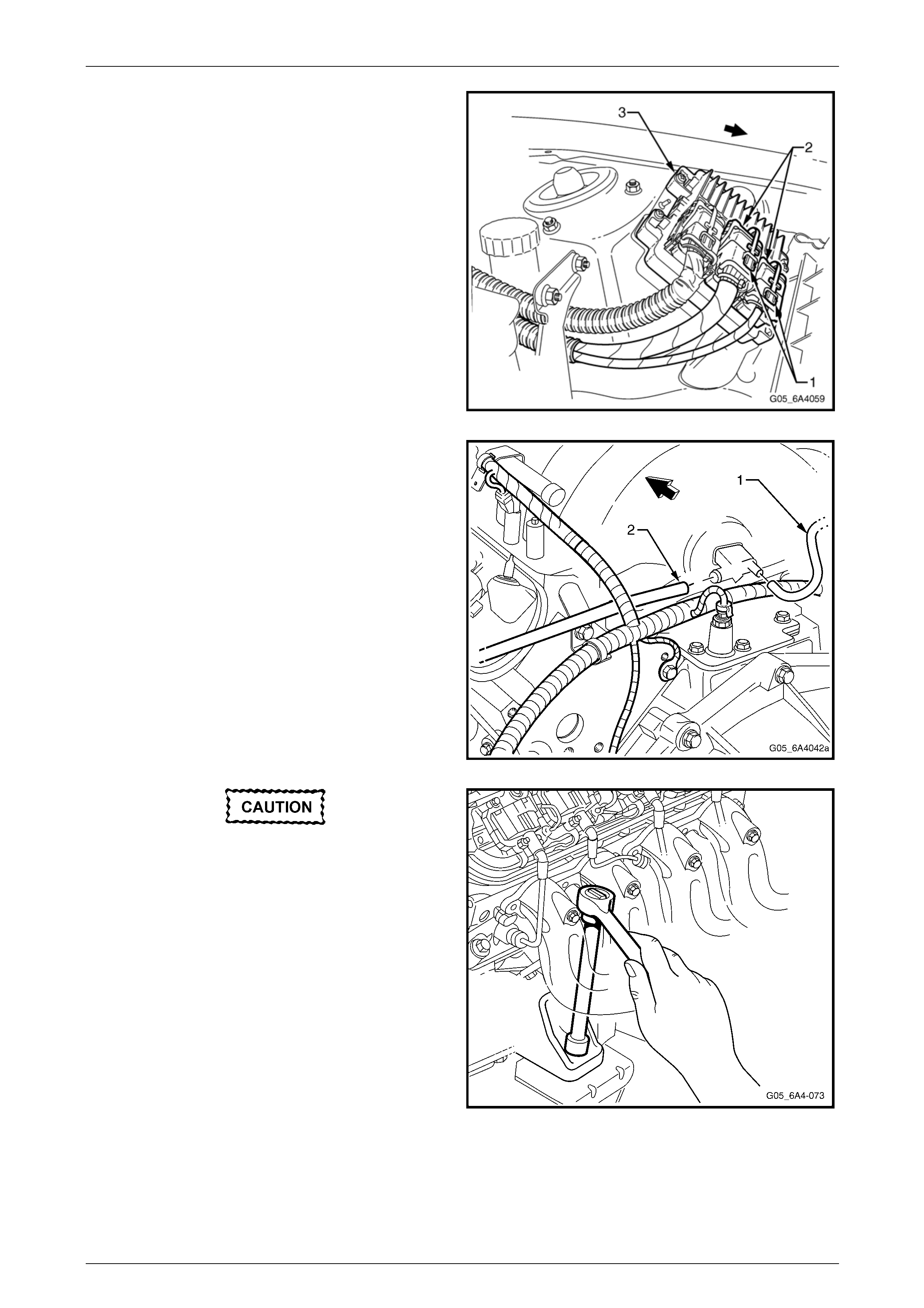
24 Loosen the power steering re servoir return hose
securing clamp (1) enough to enable the hose (2) to
be removed from the reservoir.
25 Place a suitable container under the reservoir, remove
the hose and drain the reserv oir fluid.
26 Secure the hose to one side using tie wire or similar.
NOTE
• If removing the reservoir from the engine,
repeat steps 25 and 26 for the other hose.
• Plug both openings to prevent fluid leaking
and entry of dirt.
Figure 6A4 – 87
27 Loosen and remove the high pressure line flare nut (1)
and O-ring (2) from the pump outlet fitting at the side
of the power steering pump. Use a back- up spanner
on the outlet fitting when looseni ng the flare nut.
28 Remove the hose clamp (3) and remove the hose from
the pump.
NOTE
Plug both openings to prevent fluid loss and/or
entry of dirt.
Figure 6A4 – 88
Engine Mechanical – HSV – Gen IV V8 Page 6A4–49
Page 6A4–49
29 Remove the two CPA locks (1) retaining the engine
wiring harness connectors (2) to the Engine Control
Module (ECM) (3). NOTE
The two engine wiring harness connectors are
Black and Grey. The Blue connector is for the
front body harness. For further wiring harness
service information, refer to Section 12O Fuses,
Relays and Wiring Harnesses.
30 Disconnect the engine wiring harness con ne ctors from
the ECM and feed the harness underneath the brake,
and if fitted, the clutch master cylinders.
31 Remove the wiring harness clips attachin g the harness
to the dash panel and lay the harness on top o the
engine. NOTE
Position the wiring harness on the eng ine so that
it will not be damaged while lifting the engine
from the vehicle. Figure 6A4 – 89
32 Remove the HVAC vacuum hose (1) and the brake
booster hose (2).
Figure 6A4 – 90
Handle the spark plug boot only. Do not pull
on the lead. To remove the lead, twist the
boot first to break the seal and then gently
pull on the boot.
33 Remove the No. 3 spark plug lead and plug from the
left-hand bank. NOTE
To improve access to the upper en gine mount to
bracket nuts, remove both exhaust manifolds.
Refer to Section 6A3 Engine Mechanical -
3.14 Exhaust Manifold in the MY 2004 Holden
VZ Service Information.
34 Remove the upper left engine mount to engine bracket
nut.
35 Remove the No. 4 spark plug lead and plug from the
right-hand bank.
36 Remove the upper right engine mount to en gine
bracket nut. To assist in the engine removal process,
remove the lower mount retaining nut.
Figure 6A4 – 91
37 Remove the ignition coil and module for cylinder No. 7. Refer to Section 6C4 Powertrain Management - GEN IV V8.
Engine Mechanical – HSV – Gen IV V8 Page 6A4–50
Page 6A4–50
NOTE
This step is necessary to gain additional
clearance around the brake vacuum booster
when the engine is lifted during the removal
process.
38 For manual transmission equipped vehicles, remove the bolt attaching the clutch master cylind er reservoir bracket
to the end of the master cylinder. Refer to Section F Transmission.
NOTE
This step is necessary to reduce the possibi lity of
damage to the reservoir during the engine
removal procedure.
39 Raise the vehicle front and rear and su pport on safety stands or a hoist. For the location of jacking, lifting and
support points, refer to Section 0A General Information.
40 Remove the three bolts and nuts attaching the propeller shaft front coupling and disconnect the propeller shaft from
the front spigot. Refer to Section 4C1 Rear Propeller Shaft and Universal Joints .
NOTE
It may be necessary to remove the two centre
bearing to under body attaching bolts and lower
the propeller shaft. Use tie wire to secure the
sliding yoke to the rear of the transmission.
41 Disconnect the gear shift control from the transmission.
Refer to either, Section F Transmission or Section 7C4 Automatic Tr ansmission – 4L60E – On Vehicle Servicing.
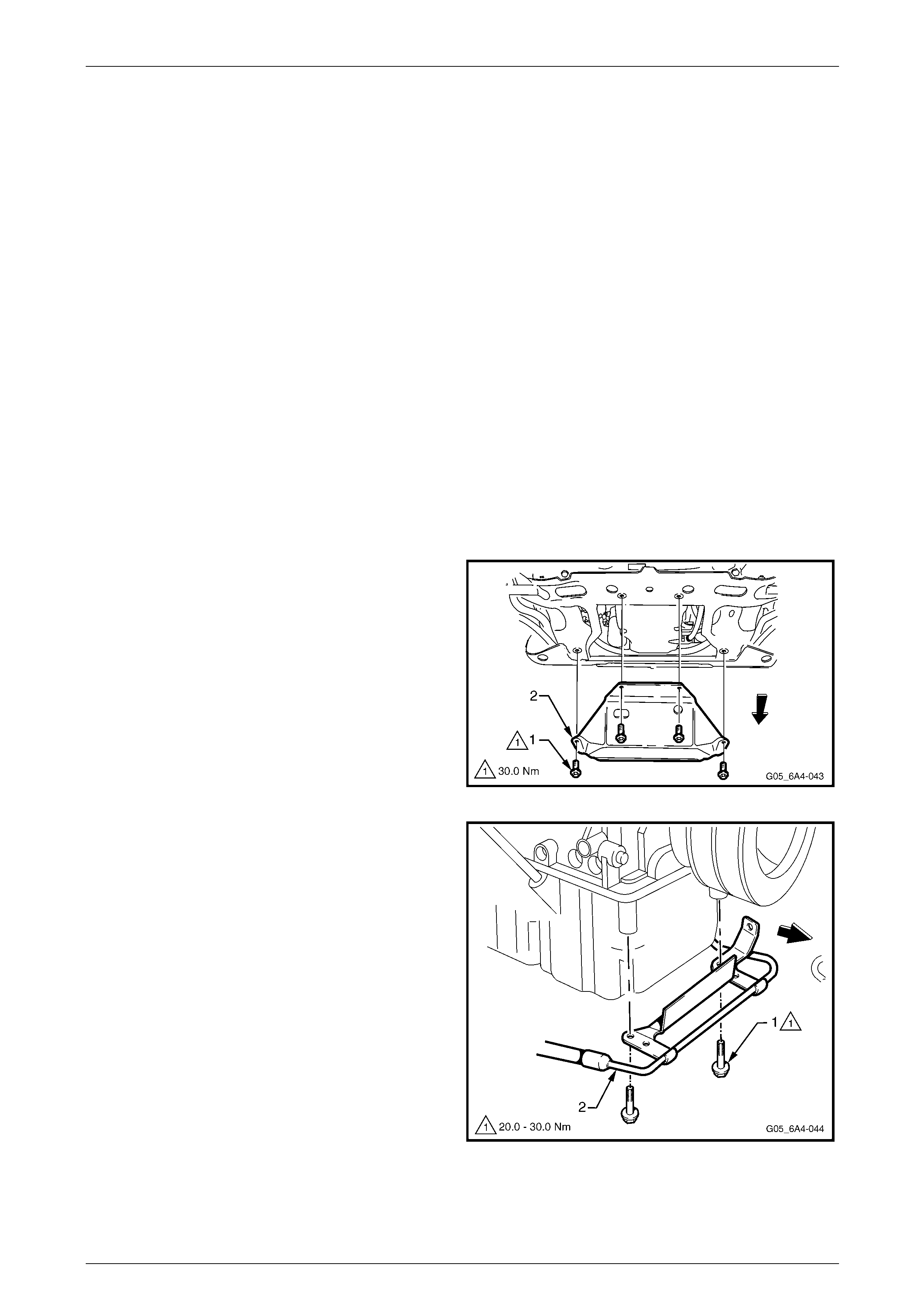
42 From under the front of the vehicle, remove the four
bolts (1) attaching the oil pan under-tray (2)
Figure 6A4 – 92
43 Remove the two bolts (1) attaching the power steering
high pressure line (2) to the oil pan.
44 Remove left and right-hand exhaust pipe to manifold
flange nuts. Refer to Section 8B Exhaust S ystem and
disconnect the exhaust system.
NOTE
While not essential, it is recommended that the
oxygen sensors be removed from the exhaust
pipes, to avoid accidental damage.
Refer to Section 6C4 Powertrain Management –
GEN IV V8.
45 Remove the transmission to exhaust reson ator
brackets. Refer to Section 8B Exhaust System.
46 Lower the vehicle to the ground.
Figure 6A4 – 93
Engine Mechanical – HSV – Gen IV V8 Page 6A4–51
Page 6A4–51
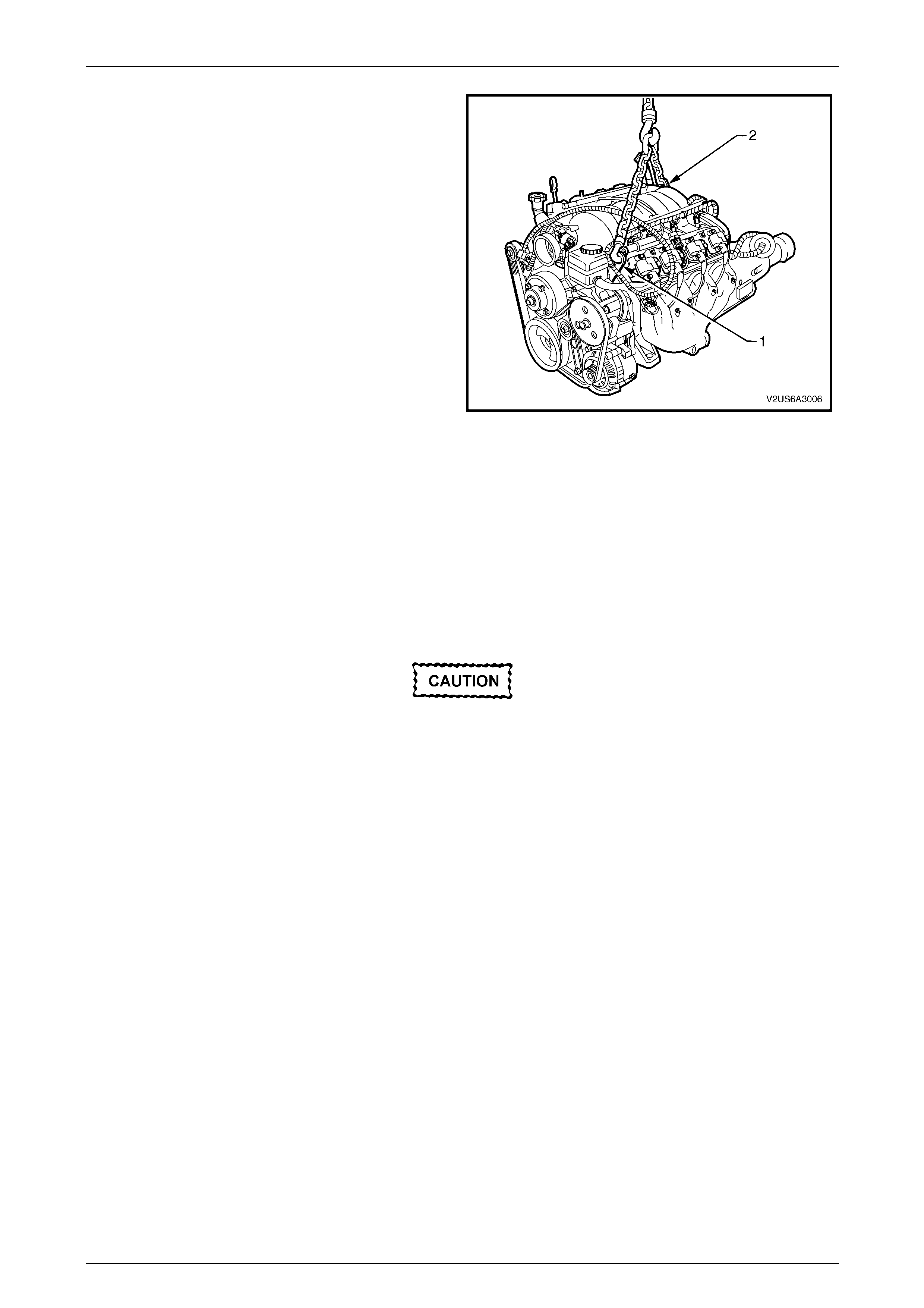
47 Attach a suitable lifting chain and hooks to the engine
lifting brackets located at the left-hand front (1) and
right-hand rear (2) of the engine.
48 Using a suitable lifting crane, raise the eng ine slightly
to take the weight off the engine mounts.
Figure 6A4 – 94
49 Mark the relationship of the engine rear cros smember (1) to the vehicle to assist with alignment on reassembly,
refer to Figure 6A4 – 95. For further information relating to cr ossmember alignment, refer to
Section 1A2 Body Dimensions in the MY 2004 Holden VZ Service Information.
NOTE
This step is critical to ensure correct powertrain
alignment on reassembly. If this is not carried out,
vehicle vibration and/or handling problems could
result.
Support the weight of the transmission by
using a suitable floor jack placed under the
transmission to prevent personal injury.
50 Place a floor jack with a block of wood under the transmission. Raise the j a ck slightly to support the weight of the
transmission.
51 Referring to Figure 6A4 – 95, remove the bolt (1), four places, attaching the rear crossmember (2) to the vehicle.
NOTE
View A is for Manual Transmission vehicles and
View B is for Automatic transmission vehicles.
52 Remove the rear mounting to crossmemb er attachin g nut (3), two places, and then remove the crossmember from
the vehicle.
a For vehicles with manual transmission, remove the rear mount to transmission bolt (4), four places and the
exhaust resonator bracket base to transmission extension bolt (5) and nut, two places and remove the
bracket base (6) from the vehicle, refer to Figure 6A4 – 95 View A.
b For vehicles with automatic transmission, remove the rear mount to transmission extension housing bolt (7),
two places and nut (8), two places and remove the mount 9) and the exhaust resonator bracket base (10)
from the vehicle, refer to Figure 6A4 – 95 View B.
c Raise the engine and transmission assembly with the front tilted upward and a floor jack supporting th e rear
of the transmission assembly.
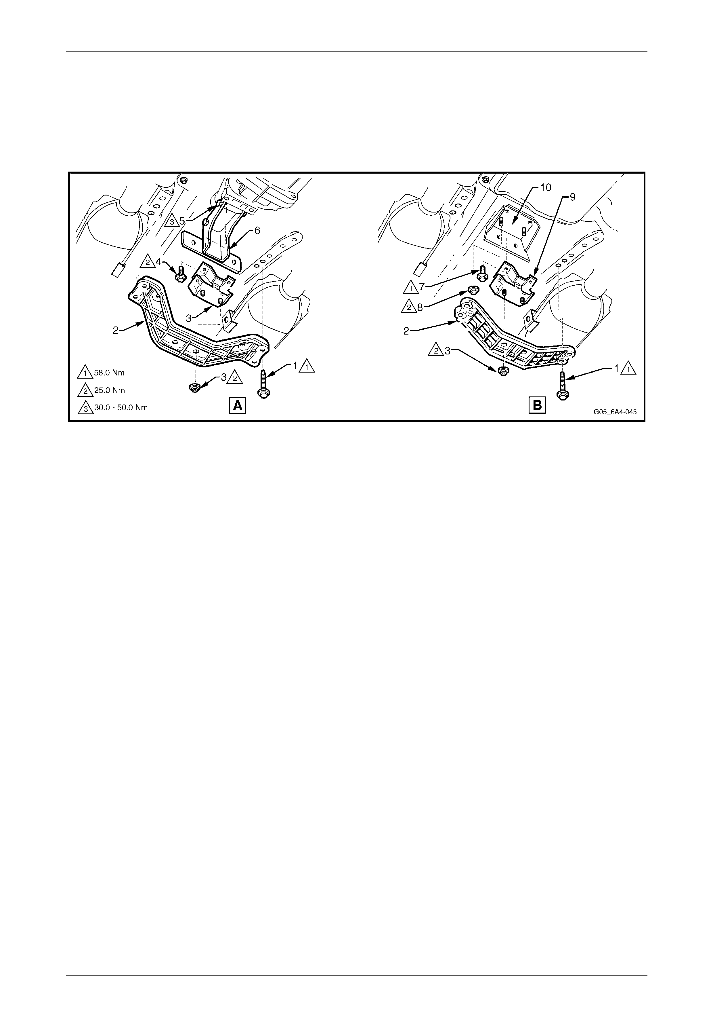
Engine Mechanical – HSV – Gen IV V8 Page 6A4–52
Page 6A4–52
NOTE
Take care when removing the engine and
transmission assembly that no part of the
assembly is allowed to rest on the power steering
rack. Do not allow the engine to swing forward
and damage the air conditioni ng condenser.
53 Continue to lift and manoeuvr e the en gine and transmission assembly until it is clear of the en gine bay.
Figure 6A4 – 95
Disassemble
1 Remove the wiring harness conn ectors and earth connections from the engine and transmission assembly and
carefully set the wiring harness to one side. For further information,
refer to Section 12O Fuses, Relays and Wiring Harnesses.
2 Remove the transmission assembly from the eng ine. For manual transmission, refer to
Section 7B4 Manual Transmission – GEN IV V8 and for automatic transmission, refer to
Section 7C4 Automatic Transmission – 4L65E – On Vehicle Servicing.
3 Mount the engine assembly on a suitab le engine stand, such as Tool No AU 591 or similar. Preferably, mount the
engine on from its side using the engine mount bracket bolt holes.
NOTE
If the engine is to be dismantl ed and in particular,
the camshaft is to be removed, then the camshaft
lobe lift check should be carried out, prior to the
removal of the cylinder heads.
4 Remove the following components as described in either this Section or other designated Sections:
• Oil filter, refer to Section 6A3 Engine Mechanical - 3.3 Engine Oil Filter and Adapter in the MY 2004 Holden
VZ Service Information.
• Engine drive belts, refer to Section 6A3 Engine Mechanical - 3.6 Engine Drive Belts and Pulleys in the
MY 2004 Holden VZ Service Information.
• Air conditioning compressor, refer to
Section 2B HVAC Climate Control (Manual A/C) – Servicing and Diagnosis.
• Engine accessory drive belt idler and tension pulley assemblies.
• Air conditioning drive belt idle r and tension pulley assemblies, refer to Section 6A3 Engine Mechanical -
A/C Drive Belt Idler Pulley and A/C Drive Belt Tensioner in the MY 2004 Holden VZ Service Information.
• Alternator and mounting brackets, refer to Section 6D4-1 Charging System – GEN IV V8.
• Intake manifold, refer to 2.2 Intake Manifold.
• Vapour vent pipe, refer to Section 6A3 Engine Mechanical – 3.8 Vapour Vent Pipe and Covers in the
MY 2004 Holden VZ Service Information.
• Engine valley cover, refer to 2.3 Engine Valley Cover.
• Valve rocker arm covers, refer to Section 6A3 Engine Mechanical - 3.11 Valve Rocker Arm Cover in the
MY 2004 Holden VZ Service Information.

Engine Mechanical – HSV – Gen IV V8 Page 6A4–53
Page 6A4–53
• Valve rocker arms and push rods, refer to Section 6A3 Engine Mechanical -
3.12 Valve Rocker Arms and Push Ro ds in the MY 200 4 Holden VZ Service Information.
• Oil level indicator and exhaust manifolds (if not already removed), refer to Section 6A3 Engine Mechanical -
3.5 Oil Level indicator and Tube and 3.14 Exhaust Manifold in the MY 2004 Holden VZ Service Information.
NOTE
Plug the oil level indicator hole in the oil pan to
avoid dirt entry.
• Cylinder head/s, refer to 2.5 Cylinder Head Assembly.
• Valve lifters, refer to Section 6A3 Engine Mechanical – 3.16 Hydraulic Valve Lifters in the MY 2004 Holden
VZ Service Information.
• Starter motor, refer to Section 6D4-2, Starting System – GEN IV V8.
• Crankshaft balancer, refer to Section 6A3 E ngine Mechanical - 3.17 Crankshaft Balance r in the MY 2004
Holden VZ Service Information.
• Coolant pump assembly, refer to Section 6B4 Engine Cooling – GEN IV V8.
Reassemble
Reassembly of the components listed in Step 4 in the Engine Assembly – Disassemble procedures, is the reverse of the
disassembly procedures except for specific points stated in each description for that component.
Reinstall, Set-up and Testing
Reinstallation of the engine assembly is the reverse of removal procedures noting th e following points:
1 Ensure that all fasteners are tightened to the correct torque specifications.
2 Use only the specified engine lubricant type and quantity. It is recommended that a fluorescent oil d ye s uch as the
dye contained in Tool No. J 28481-B or e qu ivalent be added to the engine oil to assist in an y future oil leak
diagnosis.
3 Fill the cooling system with the correct quantity and grade of coolant.
Refer to Section 6B4 Engine Cooling – GEN IV V8.
4 Check the automatic transmission fluid lev el.
Refer to Section 7C4 Automatic Transmission 4L60E – On vehicle Servicing.
5 Disable the ignition system. Refer to Section 6A3 Eng ine Mechanical - 2.7 Compression Check in the MY 2004
Holden VZ Service Information.
6 Crank the engine several time s and listen for any unusual noises or evidenc e that parts are binding.
7 Enable the ignition system and then start the engine and listen for unusual noises.
8 Check the vehicle oil pressur e gauge or warning lamp and confirm that the eng ine has acceptable oil pressure. If
necessary, install an oil pressure ga uge and measure the engine oil pressure.
9 Run the engine speed at about 1,000 rpm until the engine has reached normal operating temperature.
10 Listen for sticking lifters and other unusual noises.
11 Check for oil, fuel, coolant and exhaust leak s while the engine is running, stopping the engine and correcting as
required.
12 Ensure that the engine oil and coolant levels are correct.
13 Ensure the engine hood alignment is correct, refer to Section 1A4 Hood and Rear Compartment Lid In the
MY 2004 Holden VZ Service Information
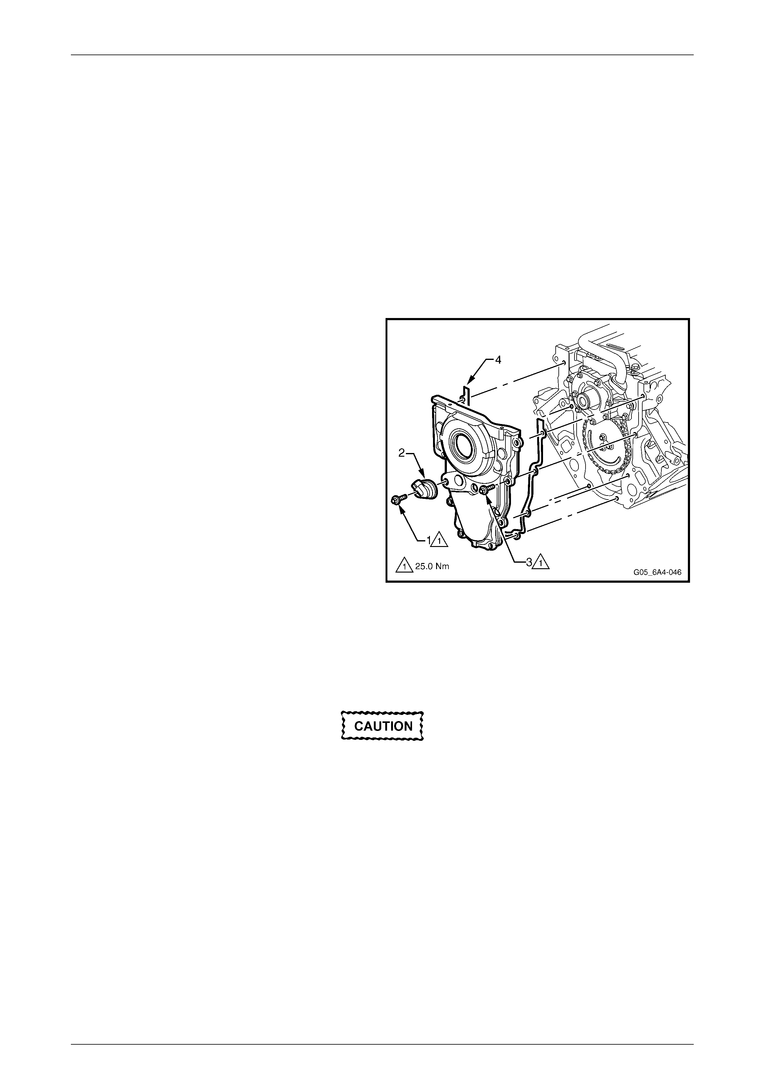
Engine Mechanical – HSV – Gen IV V8 Page 6A4–54
Page 6A4–54
3.2 Engine Front Cover
Remove
NOTE
Due to the critical alignment procedures required
for the reinstallation of the fro nt cover an d oil pan,
it is strongly recommended that the engine
assembly be removed from t he vehicle, before oil
pan removal.
1 Remove the engine oil pan.
2 Remove the crankshaft balancer.
3 Remove the camshaft sensor attaching bo lt (1), then
remove the sensor (2) from the front cover (3).
4 Remove the front cover attaching bolt (3), 10 places.
5 Remove the front cover and gasket (4).
Figure 6A4 – 96
Clean and Inspect
1 Prise the old front cover oil seal from the cover and d iscard, refer to Section 6A3 Engine Mechanical -
3.18 Crankshaft Front Oil Seal In the MY 2004 Holden VZ Service Information.
Wear the appropriate safety glasses and
gloves when using compressed air and
cleaning fluids to avoid eye and skin injury.
2 Clean the front cover in a commercially available cleaning fluid and blow dry using compressed air.
3 Inspect the front cover sealing surfaces for excessive scratches and / or gouges.
4 Inspect the front cover gasket for damage to the membrane or distortio n to the aluminium carrier.
5 Inspect the front cover to oil pan threaded holes for damaged threads or debris.
6 Inspect the cover crankshaft oil seal bore for damage.
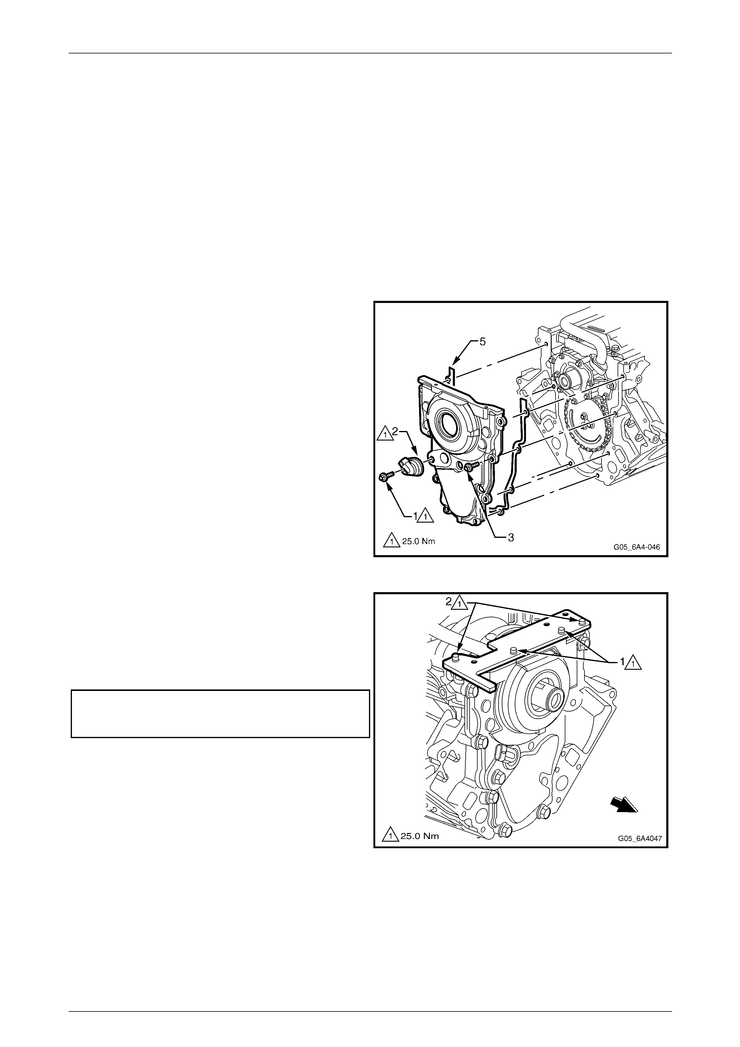
Engine Mechanical – HSV – Gen IV V8 Page 6A4–55
Page 6A4–55
Reinstall
Prior to reinstallation of the front cover, observe the following:
• Do not reuse the crankshaft front oil seal if inspection shows it to be damaged in any way.
• Do not apply any type of sealant to the front cover gasket.
• The special tools in this proce dure must be used to properly align the engine front cover at the oil pa n surface and
to centre the crankshaft front oil seal.
• All gasket surfaces should be free of oil or other foreign material during assembly.
• The crankshaft front oil seal must be centred in relation to the crankshaft and the oi l pan sealing surface at the front
cover and engine block must also be aligned within the specified limits.
• An improperly aligned front cover may cause premature front oil seal wear and/or engine assembly oil leaks.
1 Install the front cover gasket, cover and bolts onto the
engine.
2 Tighten the cover attaching bolts finger tight only.
Figure 6A4 – 97
3 Assemble alignment Tool No. J 41480 to front cover
and install the bolts (1) (part of Tool No. J 41480) in
the locations shown but do not tighten.
4 Install the alignment Tool No J 41480 bolts (2) to the
engine block and tighten to the correct torque
specification.
Front cover alignment tool
attaching bolt to engine block
torque specification............................................25.0 Nm
Figure 6A4 – 98
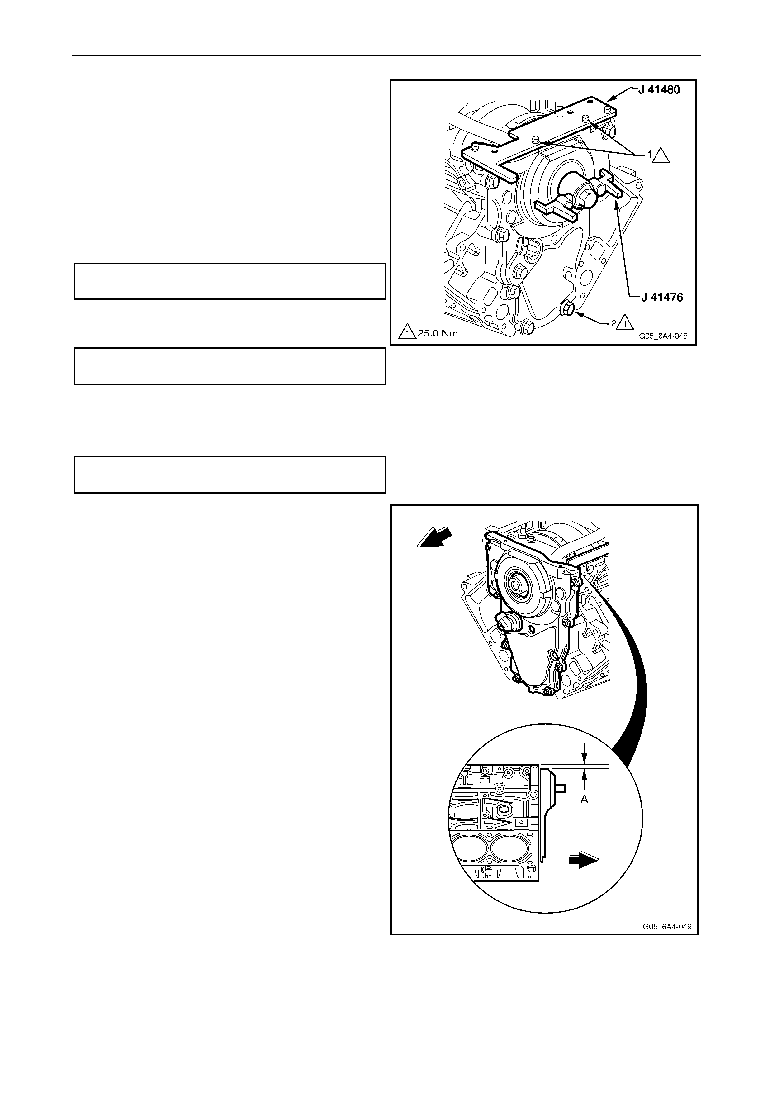
Engine Mechanical – HSV – Gen IV V8 Page 6A4–56
Page 6A4–56
5 Install centralising Tool J 414 76 as shown and hold in
position by hand. Align the tapered legs of th e tool with
the machined alignment surfaces on the front cover.
NOTE
Do not tighten the crankshaft balancer bolt to
retain the alignment tool. If the bolt is installed
and over-tightened the alignment tool will be
damaged.
6 Tighten the bolt (1), two places, attaching Tool No. J
41480 to the front cover to the specified torque.
Alignment tool to front cover
bolt torque specification.....................................25.0 Nm
7 Tighten the engine front cover attaching bolts (2) to
the correct torque specification.
Engine front cover attaching bolt
torque specification............................................25.0 Nm
8 Remove the alignment tools.
9 Reinstall the camshaft sensor and tighten the
attaching bolt to the correct torque specification.
Camshaft sensor attaching bolt
torque specification............................................25.0 Nm
Figure 6A4 – 99
9 Measure the oil pan surface to front cover for flatness,
as follows:
a Place a straight edge across the engine block
and the front cover oil pan sealing surfaces.
Avoid contact with the portion of the gasket that
protrudes into the oil pan surface.
b Insert a feeler gauge between the front cover
and the straight edge tool. T he clear ance should
not exceed 0.25 mm (A).
c If the front cover-to-engine block oil pan surf ace
alignment is not within specifications, repeat the
cover alignment procedure.
10 If the correct front cover to engine block alignment
cannot be obtained, replace the front cover.
11 Reinstall the crankshaft front oil seal. Refer to
Section 6A3 Engine Mechanical -
3.18 Crankshaft Front Oil Seal In the MY 2004 Holden
VZ Service Information.
12 Reinstall the crankshaft bala ncer, refer to Section 6A3
Engine Mechanical - 3.17 Crankshaft Balancer In the
MY 2004 Holden VZ Service Information.
13 Reinstall the oil pan. Refer to Section 6A 3 Engine
Mechanical - 4.3 Oil Pan Assembly , Except AWD In
the MY 2004 Holden VZ Service Information.
Figure 6A4 – 100
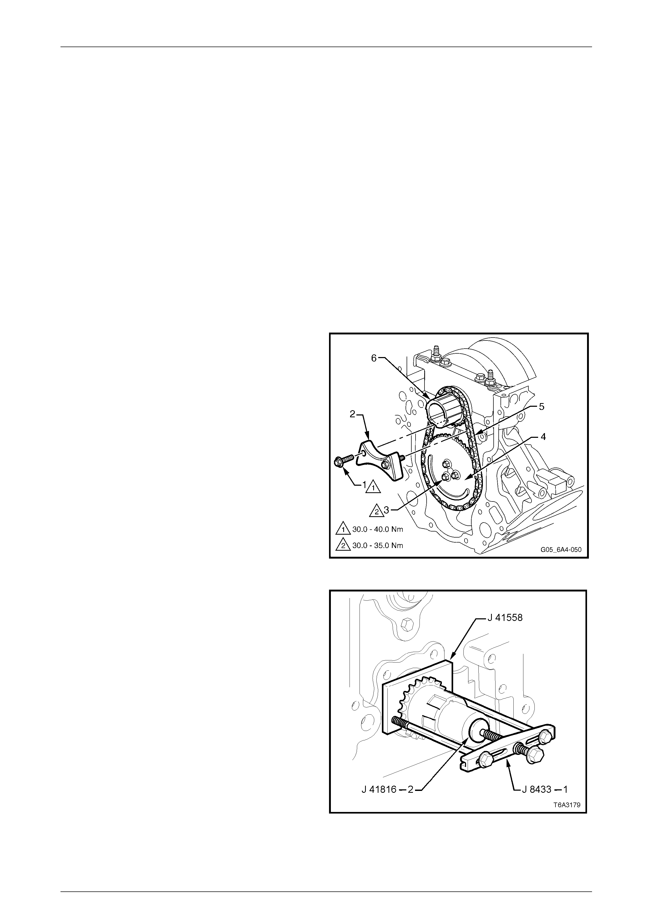
Engine Mechanical – HSV – Gen IV V8 Page 6A4–57
Page 6A4–57
3.3 Timing Chain and Sprockets
Remove
NOTE
Because of the critical alignment procedures
required for the reinstallation of the front cover
and oil pan, it is strongly recommended that the
engine assembly be removed from the vehicle
before this service operation is carried out.
1 Remove the oil pan, refer to Section 6A3 Engine Mechanical - 4.3 Oil Pan Assembly , Except AWD In the MY 2004
Holden VZ Service Information.
2 Remove the front cover, refer to 3.2 Engine Front Cover.
3 Temporarily install the harmonic balancer bolt and turn the engine until the timing marks on the crankshaft and
camshaft sprockets are aligned, refer to Figure 6A4 – 107 and then remove the crankshaft balancer bolt.
4 Remove the oil pump, refer to Section 6A3 E ngine Mechanical - 4.9 Oil Pump, Pump Screen and Deflector in the
MY2004 Holden VZ Service Information.
5 Remove the bolt (1), two places, attaching the timing
chain dampener (2) to the cylinder block.
6 Remove the three camshaft sprocket attaching bolts
(3), and then remove the sprocket (4) and chain (5)
from the camshaft.
Figure 6A4 – 101
7 Use Tool No’s J 41558, J 41816-2, the b olts from
J 21427-01 and puller J 8433 -1 to remove the
crankshaft sprocket from the nose of the crankshaft
8 Remove the crankshaft sprocket drive key from the
crankshaft nose, if required.
Figure 6A4 – 102
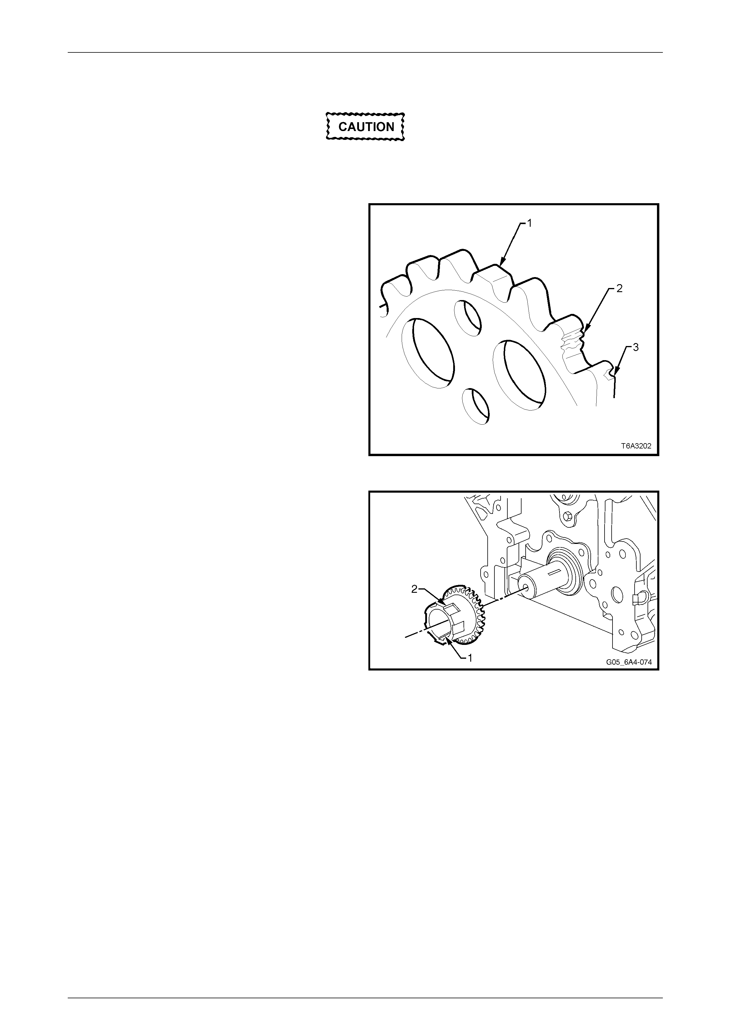
Engine Mechanical – HSV – Gen IV V8 Page 6A4–58
Page 6A4–58
Clean and Inspect
Wear the appropriate safety glasses and
gloves when using compressed air and
cleaning fluids to avoid eye and skin injury.
1 Clean the sprockets and timing chain in a
commercially available cleaning fluid and blow dr y
using compressed air.
2 Inspect the timing chain for binding or wear.
3 Inspect the camshaft and crankshaft sprockets for:
• Worn or broken teeth (1).
• Damaged teeth (2)
• Chipped teeth (3)
• Worn valleys between the sprocket teeth
Figure 6A4 – 103
4 Inspect the crankshaft sprocket keyway (1) for wear.
5 Inspect the crankshaft sprocket oil pump drive splines
(2) for wear.
Figure 6A4 – 104
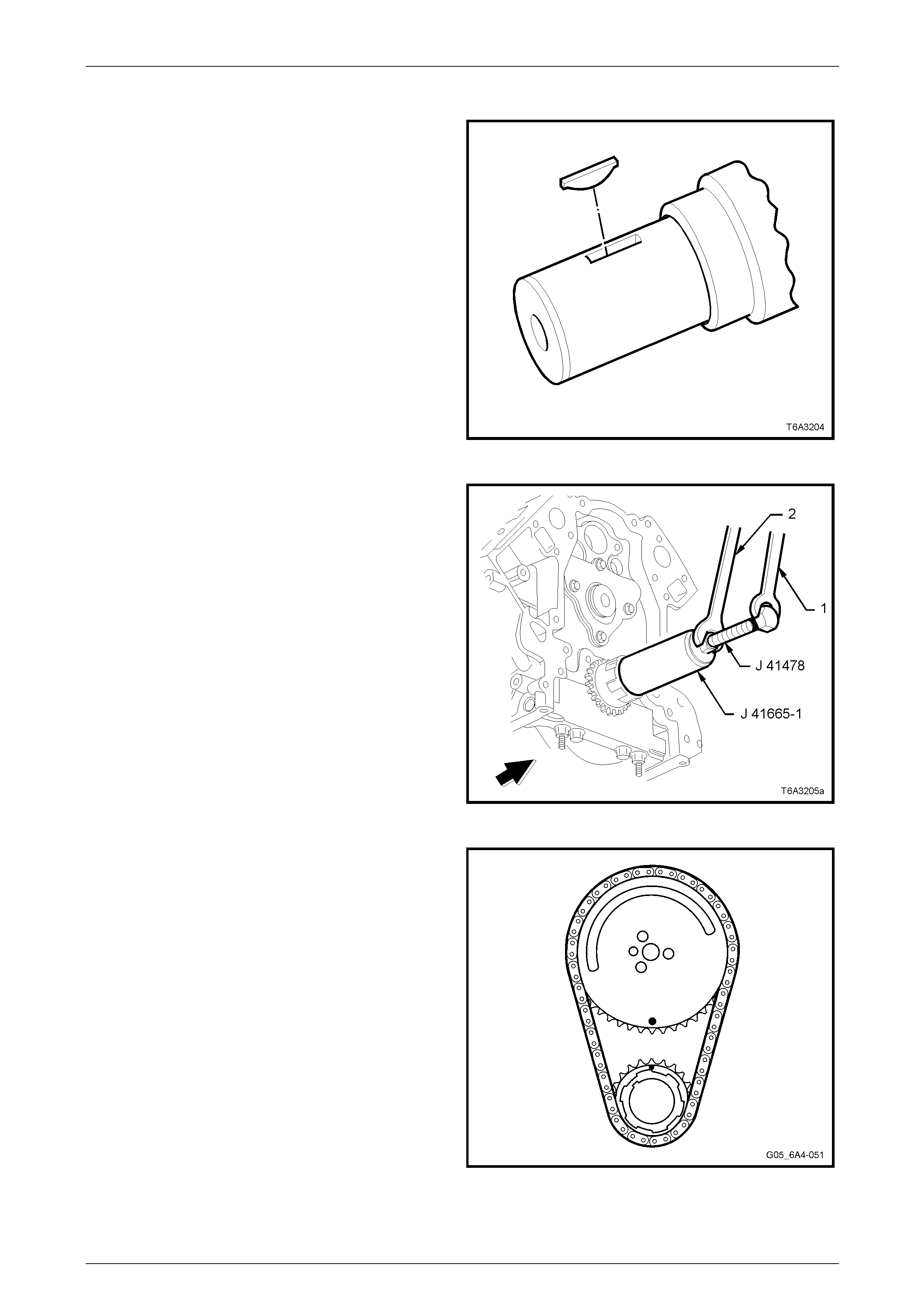
Engine Mechanical – HSV – Gen IV V8 Page 6A4–59
Page 6A4–59
Reinstall
1 If removed, reinstall the crankshaft sprocket drive
keyway into the crankshaft. The key should be tapped
into place until each end bottoms on the crankshaft.
2 Reinstall the crankshaft sprocket onto the cranksh aft
aligning the keyway with the key.
Figure 6A4 – 105
3 Use the installer Tool No. J 41665 to reinsta ll the
crankshaft sprocket, as follows:
a Install the threaded bolt, nut and flat washer from
Tool No. J 41478 through the end plate and
stepped sleeve of Tool No. J 41665-1.
b Screw the threaded bolt into the crankshaft,
using a spanner (1).
c While holding the threade d bo lt with the spanner,
turn the nut with a second set spanner (2),
moving the installer Tool No. J 41665 to fully
install the crankshaft sprocket onto the
crankshaft nose.
d When the crankshaft sprocket has been fully
installed, remove the installation tools.
4 If required, temporarily reinstall the harmo nic balancer
bolt and rotate the crankshaft until the crankshaft
timing gear alignment mark is at the 12 o’clock
position. Refer to Figure 6A4 – 107. Figure 6A4 – 106
5 Reinstall the camshaft sprocket, align ing the peg on
the camshaft with the sprocket hole. Check that the
timing mark is at the 6 o’clock position.
6 If required, temporarily install the camshaft sprocket
bolts and use a suitable lever to carefully rotate the
camshaft sprocket until the timing mark is correctl y
aligned. Remove the bolts and sprocket.
7 Install the timing chain to the camshaft sprocket. Align
the camshaft peg with the camshaft sprocket hole then
install the timing chain to the crankshaft sprocket.
8 Install the camshaft sprocket over the camshaft peg.
9 Before installing the camshaft sprocket attaching bolts,
check that the timing marks are aligned. If not, repeat
Steps 4 to 8 above.
Figure 6A4 – 107
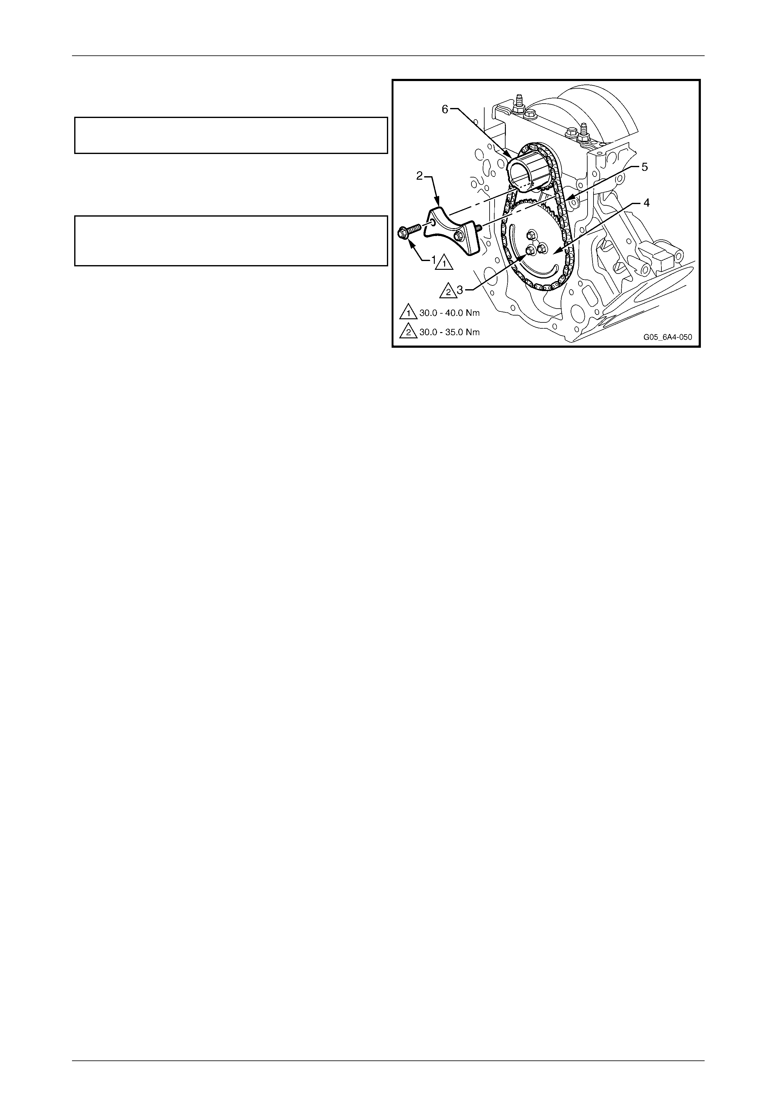
Engine Mechanical – HSV – Gen IV V8 Page 6A4–60
Page 6A4–60
10 Install the camshaft sprocket attaching bolts (3) and
tighten to the correct torque specification.
Camshaft sprocket attaching bolt
torque specification..................................30.0 –35.0 Nm
11 Reinstall the timing chain dampener (2) and tighten
the two attaching bolts (1) to the correct torque
specification.
Timing chain dampener attaching
attaching bolt
torque specification.................................30.0 – 40.0 Nm
12 Reinstall the oil pump, refer to
Section 6A3 Engine Mechanical -
4.9 Oil Pump, Pump Screen and Deflector in the MY
2004 Holden VZ Service Information.
13 Reinstall oil pan, refer to Section 6A3 E ngine
Mechanical - 4.3 Oil Pan Assembly , Except AWD In
the MY 2004 Holden VZ Service Information.
14 Reinstall the front cover and harmonic balancer.
Refer to 3.2 Engine Front Cover in this Section and
Section 6A3 Engine Mechanical -
3.17 Crankshaft Balancer In the MY 2004 Holden VZ
Service Information.
Figure 6A4 – 108
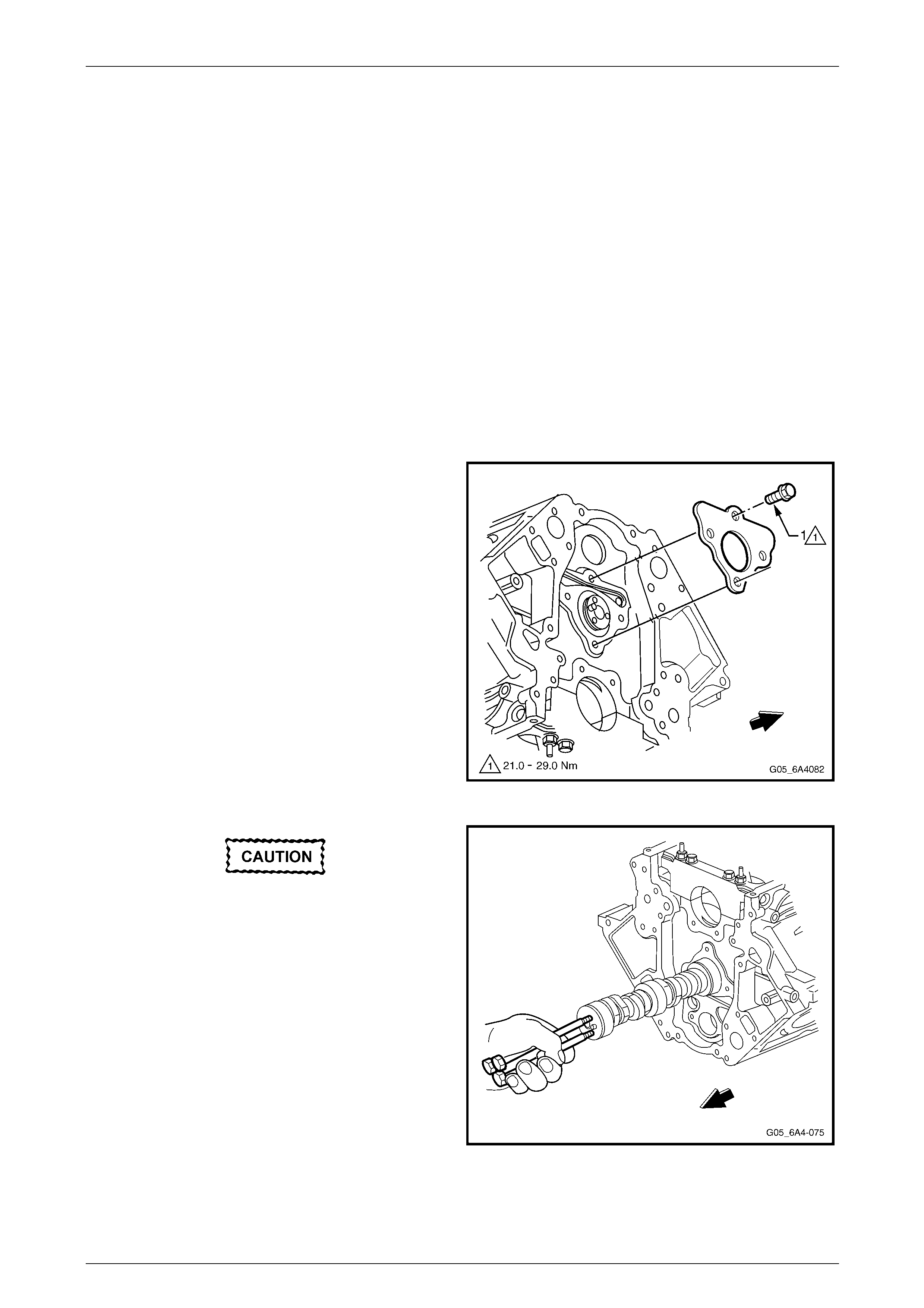
Engine Mechanical – HSV – Gen IV V8 Page 6A4–61
Page 6A4–61
3.4 Camshaft
Remove
NOTE
Because of the critical alignment procedures
required for the reinstallation of the front cover
and oil pan, it is strongly recommended that the
engine assembly be removed from the vehicle
before this service operation is carried out.
Refer to 3.1 Engine Assembly.
1 Remove the valve lifters, refer to Section 6A3 Engine Mechanical - 3.16 Hydrualic Valve Li fters In the MY 2004
Holden VZ Service Information.
2 Remove the timing chain and sprocket. Refer to 3.3 Timing Chain and Sprockets.
3 Remove the oil pump, refer to Section 6A3 E ngine Mechanical - 4.9 Oil Pump, Pump Screen and Deflector In the
MY 2004 Holden VZ Service Information.
4 Remove the camshaft retainer attaching bolts then
remove the retainer and gask et.
Figure 6A4 – 109
All the camshaft bearing journals are of the
same size, extreme care must be taken w hen
removing the camshaft.
5 Install three, M8 x 1.25 x 100 mm bolts (e.g. the
removed coolant pump bolts) in the front of the
camshaft and use them as a handle to rotat e and
remove the camshaft from the engine block.
6 Remove the three bolts from the camshaft.
Figure 6A4 – 110
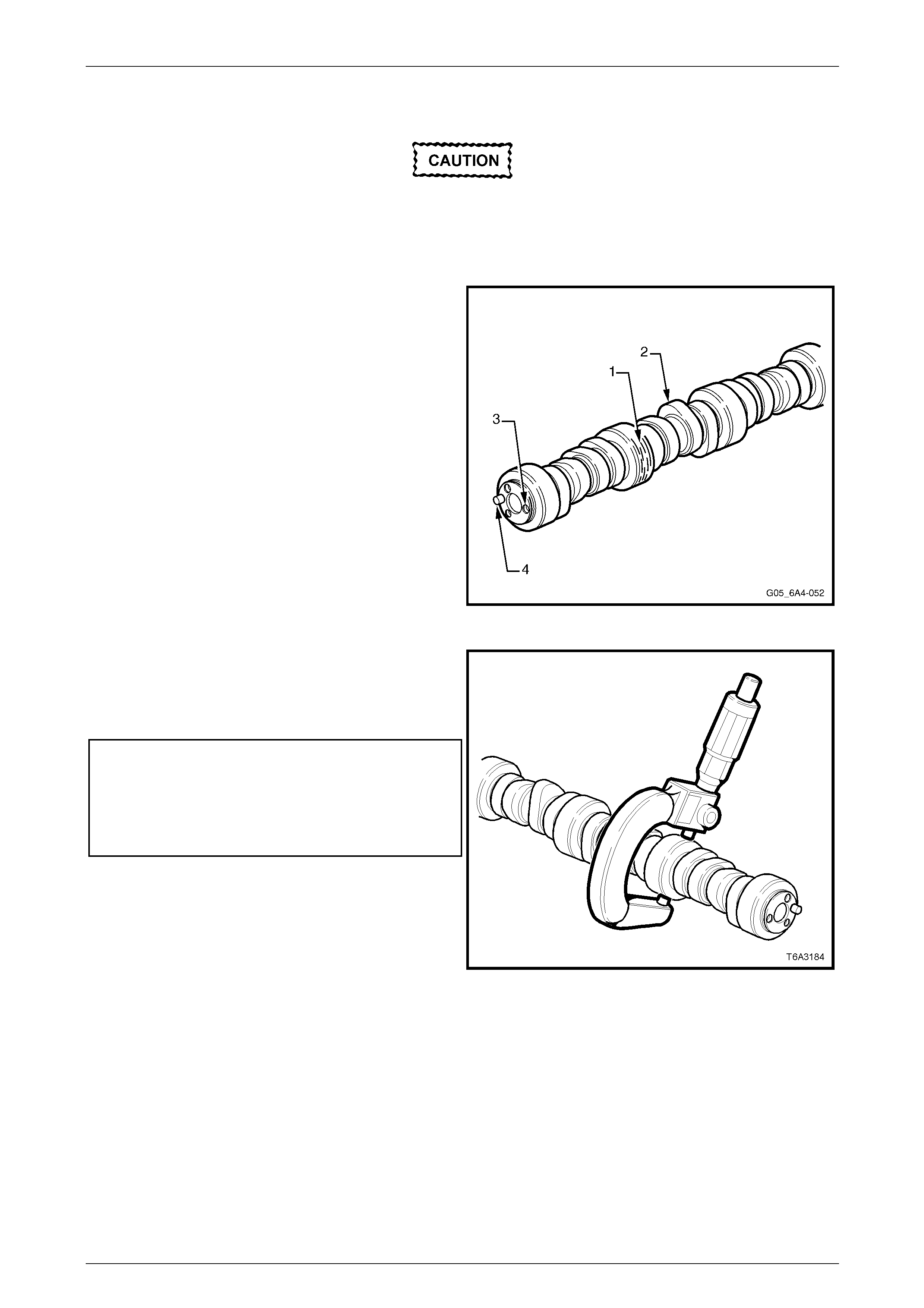
Engine Mechanical – HSV – Gen IV V8 Page 6A4–62
Page 6A4–62
Clean and Inspect
Wear the appropriate safety glasses and
gloves when using compressed air and
cleaning fluids to avoid eye and skin injury.
1 Clean all components with a suitable solvent and blow dry with compressed air.
2 Inspect the camshaft for:
a Scoring or excessive wear to the bearin g
journals (1).
b Scoring or excessive wear to the camshaft
lobes (2).
NOTE
If camshaft lobe wear is found the camshaft will
need to be replaced along with the valve lifters
as a complete set. Do not use worn lifters on a
new camshaft.
c Damaged threads (3) or debris in threaded
holes.
d Damage to the camshaft sprocket pin (4).
Figure 6A4 – 111
3 Measure the camshaft journals for wear and out-of-
round, using a micrometer.
a Replace the camshaft if either of these
measurements are outside th e specification.
Camshaft Journal Specifications:
Camshaft Journal
Out-of-Round..........................................0.025 mm Max.
Camshaft Bearing Journal
Diameter ..................................................54.99 mm Min.
Figure 6A4 – 112
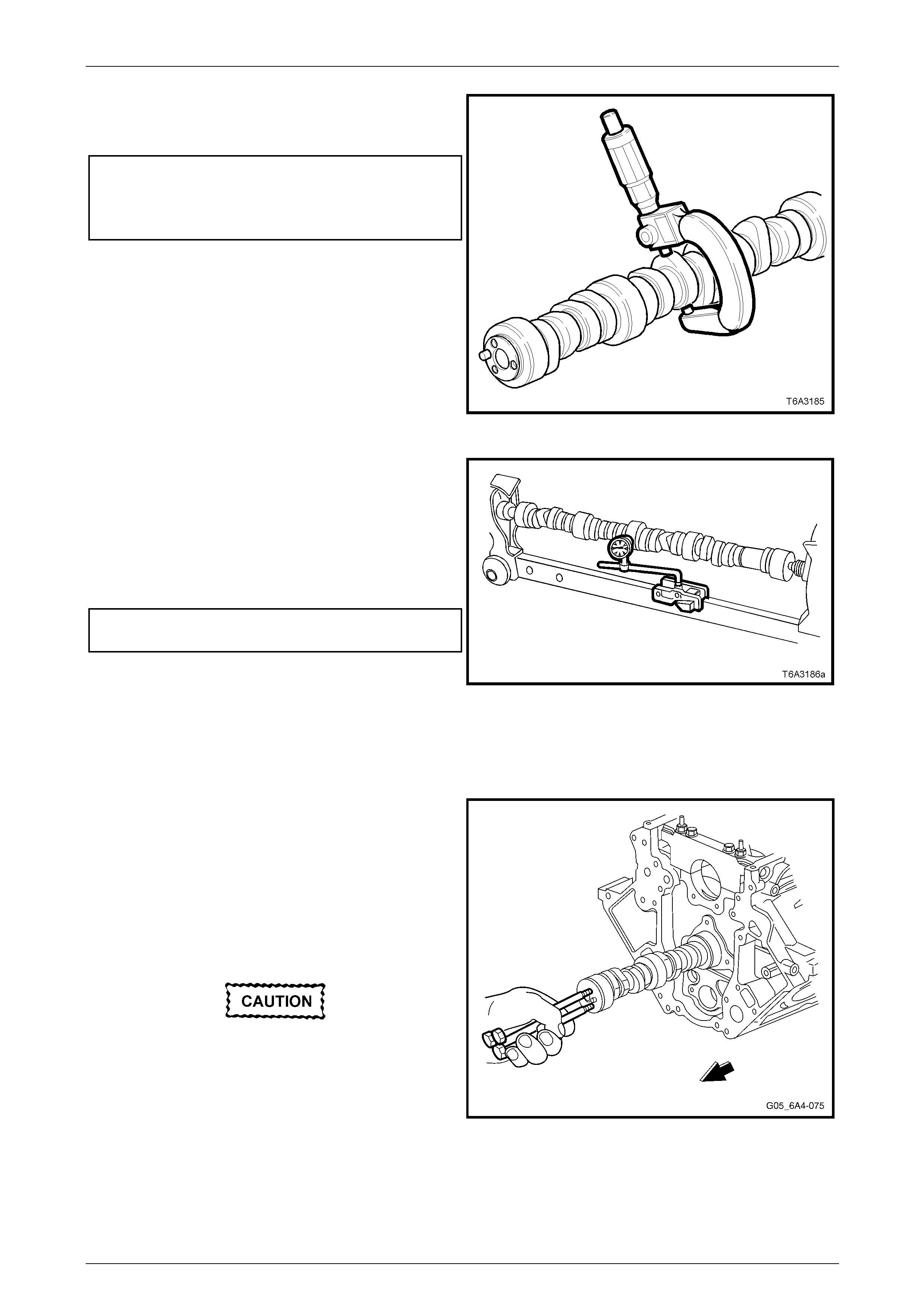
Engine Mechanical – HSV – Gen IV V8 Page 6A4–63
Page 6A4–63
4 Measure the camshaft lobes for wear using a
micrometer. Replace the camshaft if any of the
camshaft lobe dimensions are not within spec ification.
Camshaft Lobe Height Specifications:
Intake Lobe Height....................................46.33 mm Min
Exhaust Lobe Height.................................46.33 mm Min
Figure 6A4 – 113
5 Mount the camshaft either in V-blocks or between
centres.
6 Using a suitable dial indicator, rotate the camshaft and
check the runout on the centre bearing journal.
Replace the camshaft if the runout exceeds t he
specification.
Camshaft Runout Specification
Camshaft runout
Specification......................................0.05 mm Maximum
7 Inspect the camshaft retainer plate for wear or a
damaged sealing gask et. If the gasket is not cut or
damaged, it may be re-used.
Figure 6A4 – 114
Reinstall
1 Lubricate camshaft lobes, journals and the bearings
with clean engine oil.
NOTE
If camshaft replacement is required, the valve
lifters must also be renewed.
2 Install the three M8 x 1.25 x 100 mm bolts used in the
removal process into the camshaft front jour nal.
All the camshaft bearing journals are of the
same size, extreme care must be taken w hen
reinstalling the camshaft.
3 Using the bolts as a handle, careful ly install the
camshaft into the engine block.
4 Remove the three bolts after camshaft installation. Figure 6A4 – 115
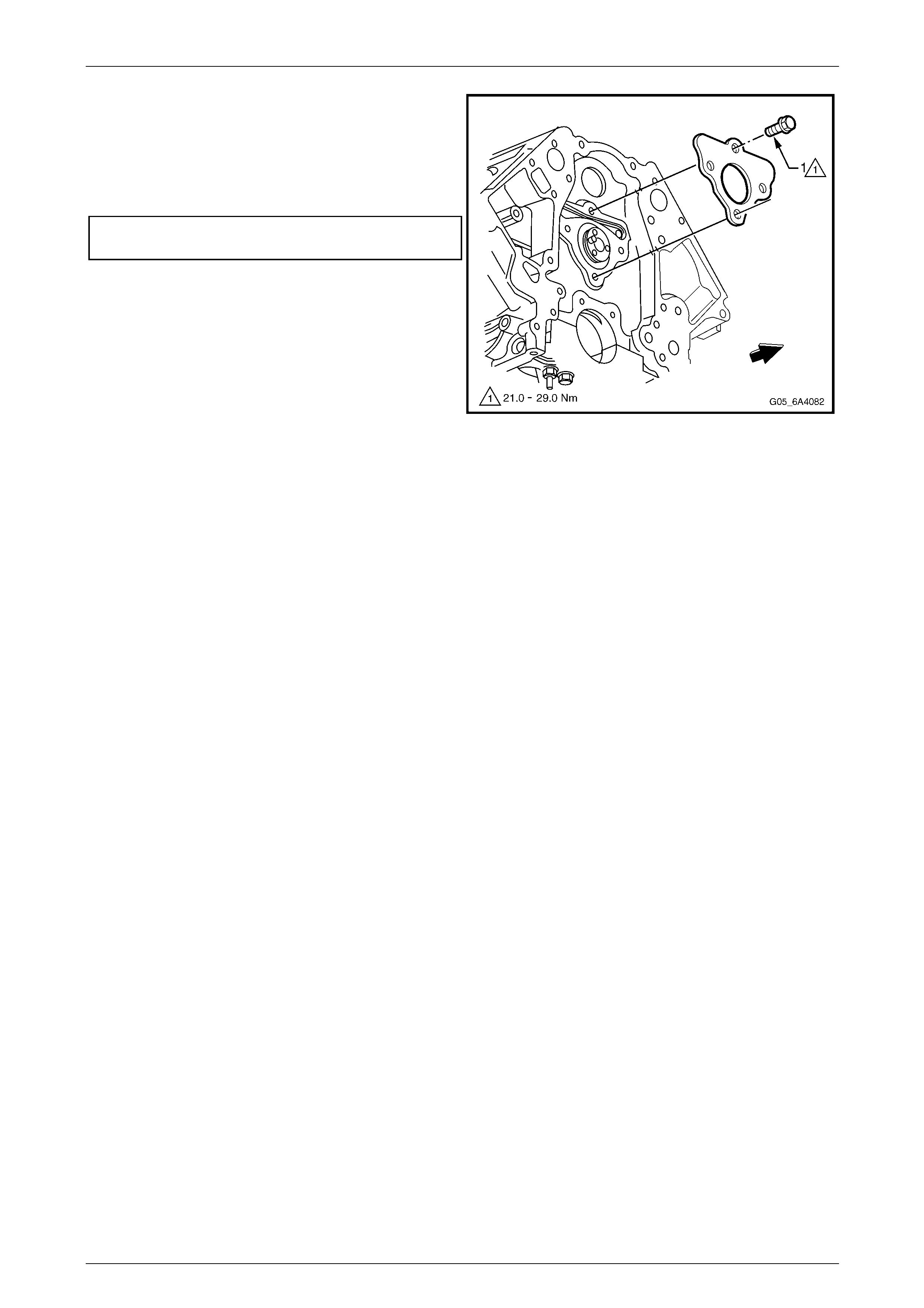
Engine Mechanical – HSV – Gen IV V8 Page 6A4–64
Page 6A4–64
5 Ensure that the engine block mating surface is clean
and free of contaminants and old g asket material, the n
install the camshaft retainer plate with the sealing
gasket facing the engine bloc k.
6 Install the camshaft retainer bolts and tighten to the
correct torque specification.
Camshaft retainer attaching bolt
torque specification.................................21.0 – 29.0 Nm
7 Reinstall the timing chain and sprocket.
Refer to 3.3 Timing Chain and Sprockets.
8 Reinstall the oil pump, refer
Section 6A3 Engine Mechanical -
4.9 Oil Pump, Pump Screen and Deflector in the
MY 2004 Holden VZ Service Information.
9 Reinstall the front cover and harmonic balancer.
Refer to 3.1 Engine Front Cover.
10 Reinstall the oil pan, refer to Section 6A 3 Engine
Mechanical - 4.3 Oil Pan Assembly , Except AWD in
the MY 2004 Holden VZ Service Information.
11 Reinstall the valve lifters, refer to Section 6A 3 Engine
Mechanical - 3.16 Hydraulic Valve Lifters in the
MY 2004 Holden VZ Service Information.
Figure 6A4 – 116
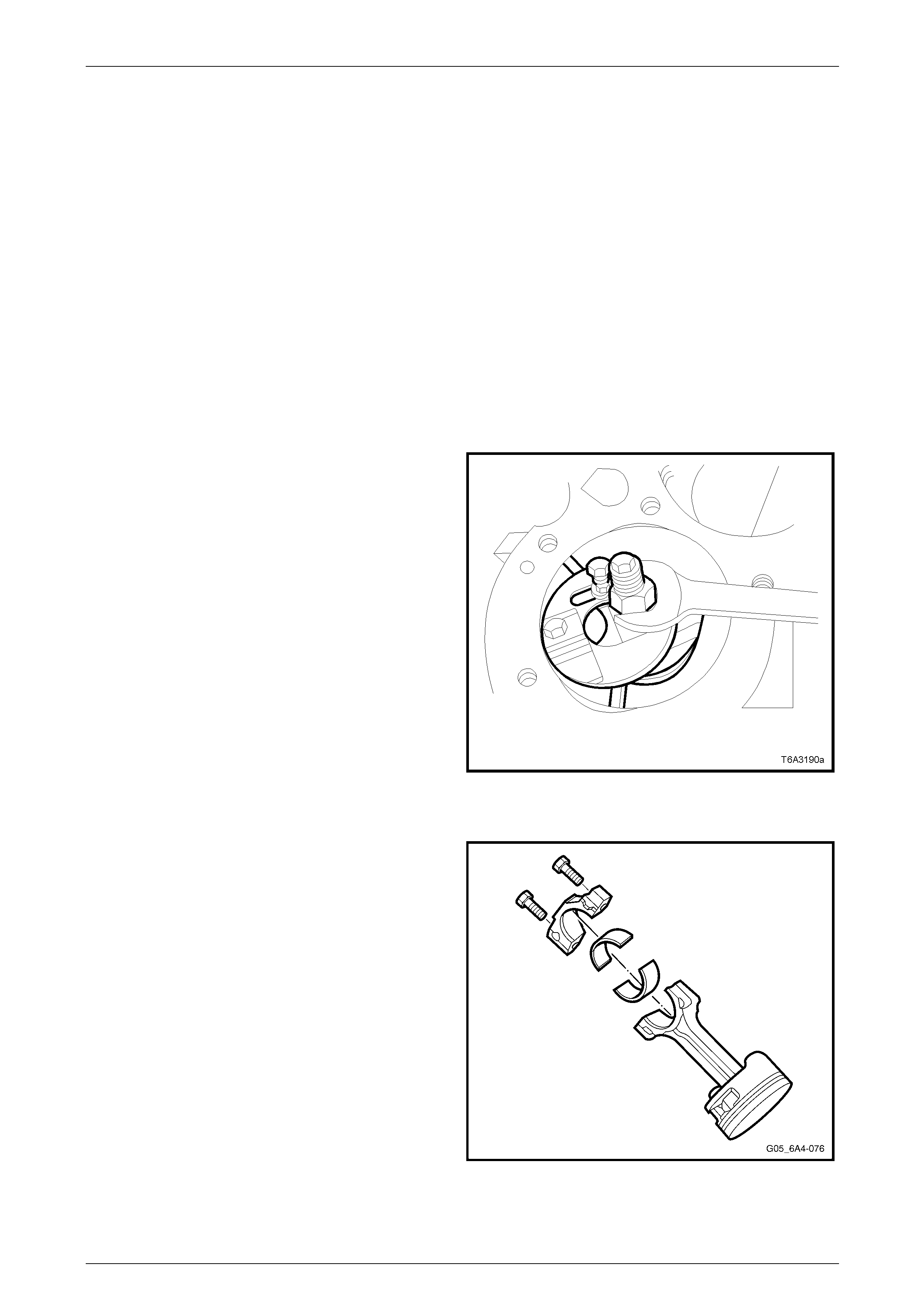
Engine Mechanical – HSV – Gen IV V8 Page 6A4–65
Page 6A4–65
3.5 Piston, Connecting Rod and Bearing
NOTE
Because of the critical alignment procedures
required for the reinstallation of the oil pan, it is
strongly recommended that the engine assembly
be removed from the vehicle before this service
operation is carried out.
Refer to 3.1 Engine Assembly.
Remove
1 Remove both the cylinder heads. Refer to 2.4 Cylinder Head Assemb ly.
2 Remove the oil pan, refer to Section 6A3 Engine Mechanical - 4.3 Oil Pan Assembly , Except AWD in the MY 2004
Holden VZ Service Information.
3 Remove the oil pump screen and deflector, r efer to Section 6A3 Engine Mechanical -
4.9 Oil Pump, Pump Screen and Cover in the MY 2004 Holden VZ Servic e Information.
4 If required, remove any cylinder ridg e present with the
following procedure:
a Rotate the crankshaft until the piston to be
serviced is at the bottom of its stroke (BDC).
b Place a cloth on top of the piston.
c Use a commercially available cylinder ridge
remover to remove the cylinder ridge.
NOTE
Follow the tool manufacturers operating
instructions and recommendations when
removing the ridge from the cylinder.
d Again rotate the crankshaft until the piston is at
the top of its stroke (TDC).
e Remove the cloth and any metal shavings from
the piston crown.
NOTE
Repeat Step 4 for the remaining cylinders as
required.
Figure 6A4 – 117
5 Using a paint stick or etching tool, mark each
connecting rod and its cap. The connecti ng rod caps
must be assembled to their original position and
direction.
NOTE
Do not apply a stampin g mark on the side of the
connecting rod and / or cap as this may affect
the alignment and the geome t ry of the assembly.
6 Mark the top of each piston to identify its specific bore.
7 Remove the connecting rod cap attachi ng bolts,
loosening progressively from side to side.
8 Remove each connecting rod cap.
NOTE
Ensure that the connecting rod caps and
bearings are organised so they can be
reinstalled to their original pos ition and location. Figure 6A4 – 118
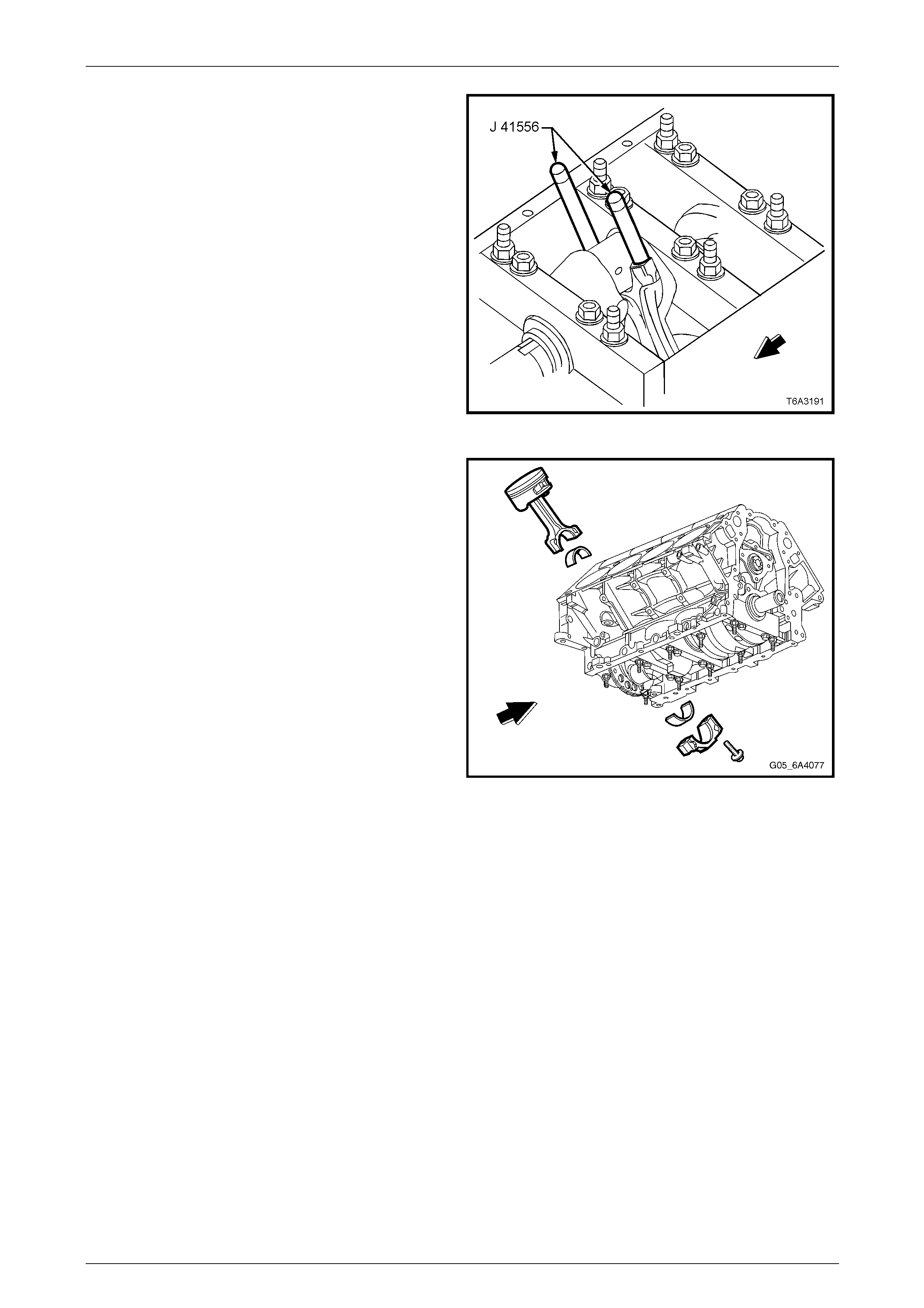
Engine Mechanical – HSV – Gen IV V8 Page 6A4–66
Page 6A4–66
9 Install guide pins, Tool No. J 41556 to the connecting
rod to be removed.
Figure 6A4 – 119
10 Using a hammer handle, li ght ly tap on the end of the
guide pin Tool No. J 4155 6 until the piston and
connecting rod assembly have been removed from the
cylinder bore.
11 Once removed, assemble the connecting rod cap,
bearing shells and bolts to the matching connecting
rod.
NOTE
New connecting rod bolts are to be used in the
reinstallation procedure.
Figure 6A4 – 120
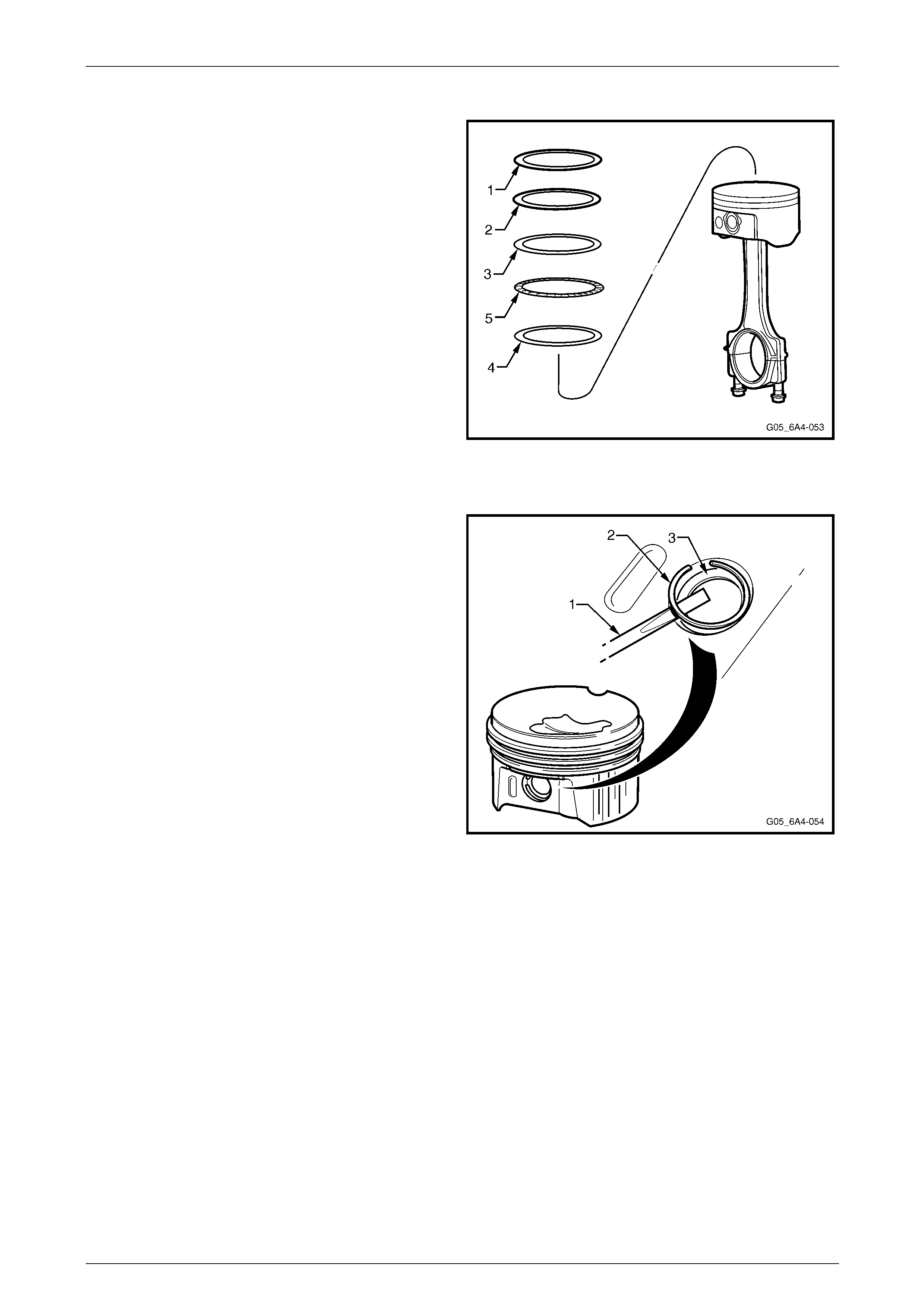
Engine Mechanical – HSV – Gen IV V8 Page 6A4–67
Page 6A4–67
Disassemble
1 Remove the piston rings from the piston in the
following order by expanding the rings using a
commercially available piston ring expander or by
hand.
a Remove the rings by lifting them over the top of
the piston.
1 Top compression ring.
2 Lower compression ring.
3 Top oil control ring.
4 Lower oil control ring.
5 Oil control segment ring.
NOTE
Only expand the piston rings enough to enable
them to clear the piston. Excessive expansion
will permanently distort the piston ring. Avoid
contact with the sides of the piston as this may
cause scratches on the piston surface. Figure 6A4 – 121
2 Use a paint or marker pen and mark the orientation of
the piston to the connecting rod and the bore number
from which it was removed.
3 Using a small scre wdriver (1), carefull y prise out the
C clip (2) retaining the piston pin (3). If required,
repeat for the other circlip.
4 Remove the piston pin from the piston and connecting
rod by pushing the pin from the piston by hand.
Figure 6A4 – 122
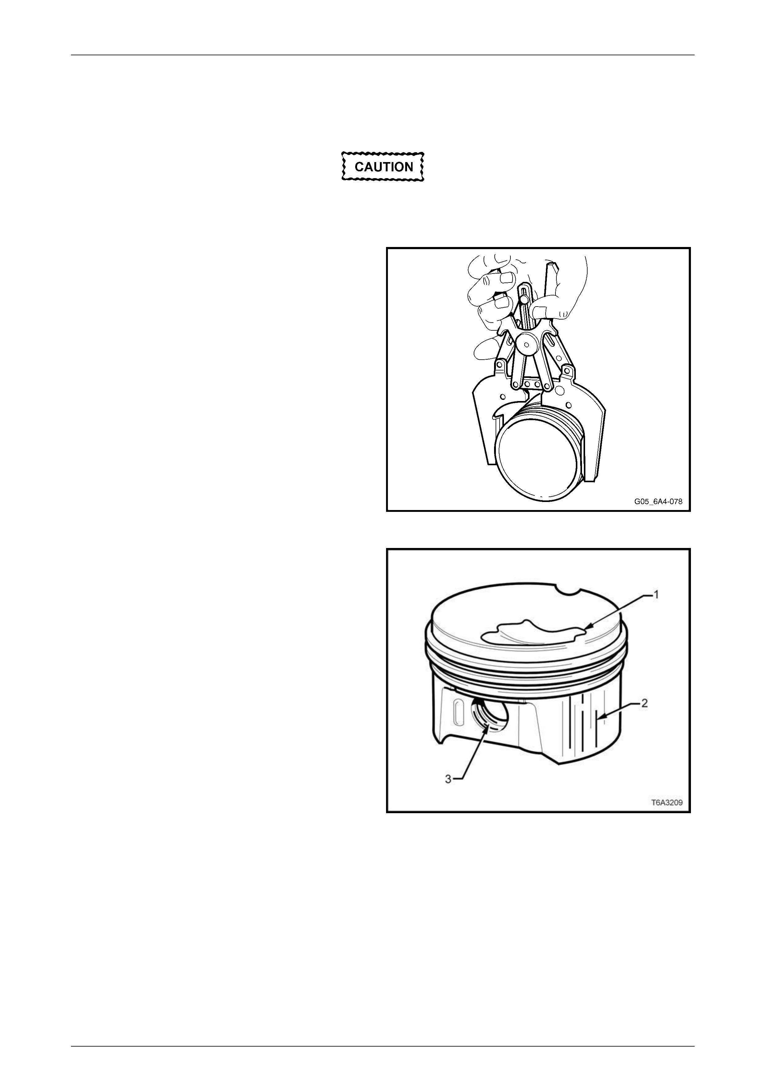
Engine Mechanical – HSV – Gen IV V8 Page 6A4–68
Page 6A4–68
Clean and Inspect
Piston and Pin
Wear the appropriate safety glasses and
gloves when using compressed air and
cleaning fluids to avoid eye and skin injury.
1 Clean any varnish from the piston and pin, with a
commercially available cleaning fluid. Do not use a
wire brush for this process.
2 Dry the cleaned parts using compressed air.
3 Clean the piston ring groov es wit h a commercially
available tool.
4 Clean the oil lubrication holes and slots in the ring
grooves.
Figure 6A4 – 123
5 Inspect each piston and pin for the following:
• Eroded areas on top of the piston (1).
• Scuffed or damaged skirts (2)
• Scoring to the piston pin bore (3) or the piston
pin
• Cracks in the piston lands, skirt or the pin bosses
• Piston ring grooves for nicks, burrs or warpage
that may cause the piston ring to bind. Minor
imperfections may be removed by using a fi ne
file
Figure 6A4 – 124
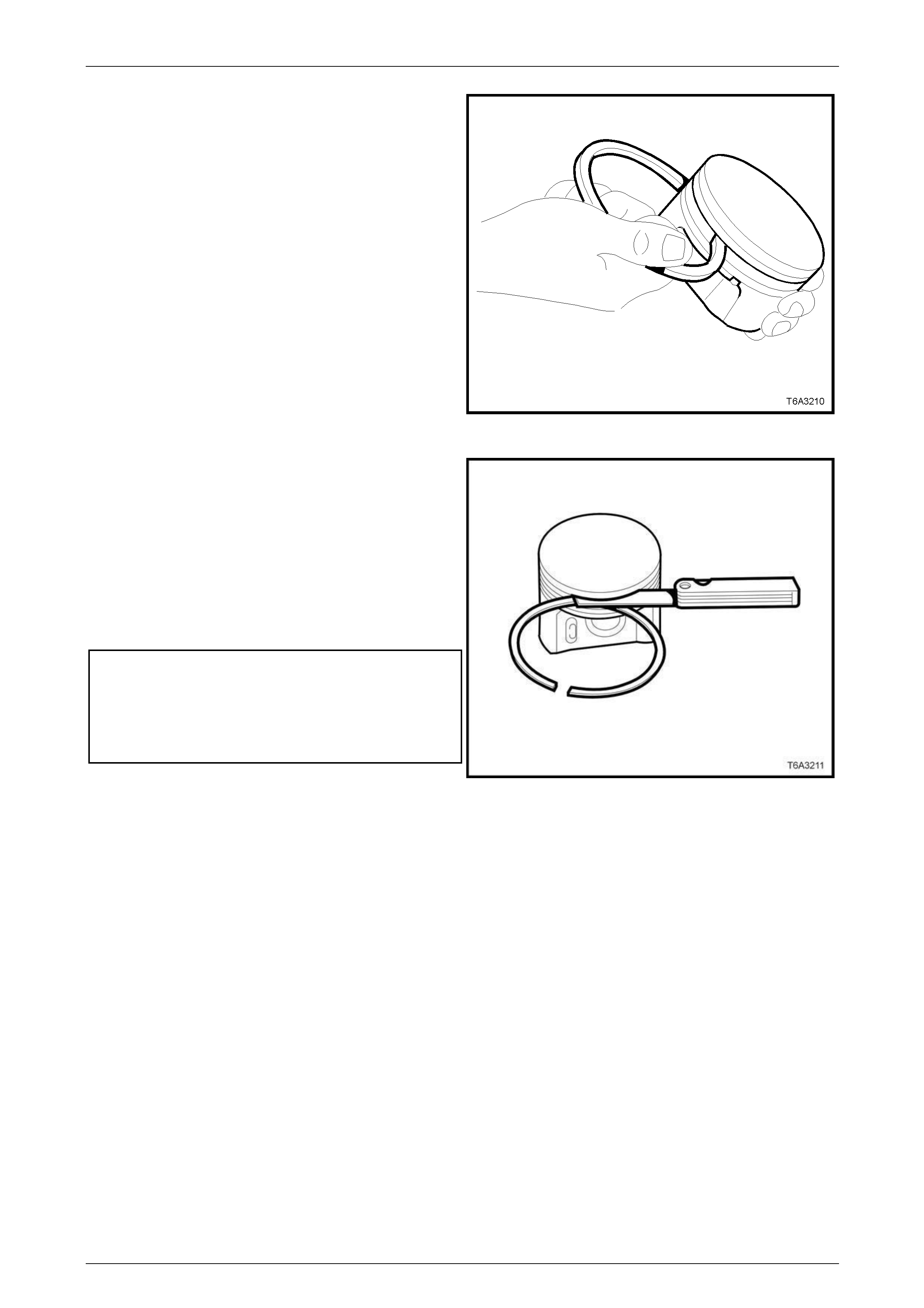
Engine Mechanical – HSV – Gen IV V8 Page 6A4–69
Page 6A4–69
6 Measure the piston ring to piston groove side
clearance, as follows:
a Insert the edge of a new piston ring into the
correct piston ring groove.
b Roll the piston ring aroun d the groove.
NOTE
If binding is caused by a distorted piston ring
groove, minor ring groove imperfections may be
removed with a fine file.
Figure 6A4 – 125
7 Insert the edge of a new piston ring into the correct
piston ring groove. Check the side clearance using a
feeler gauge.
NOTE
If the piston ring side clearance exceeds the
specification, try another piston ring set before
replacing the piston. If a second set of piston
rings fail to meet the specifications, the piston
and pin assembly must be replaced.
Piston ring side clearance specification:
Top compression ring ........................0.040 - 0.085 mm.
Second compression ring ..................0.040 - 0.080 mm.
Oil control ring....................................0.010 - 0.220 mm.
Figure 6A4 – 126
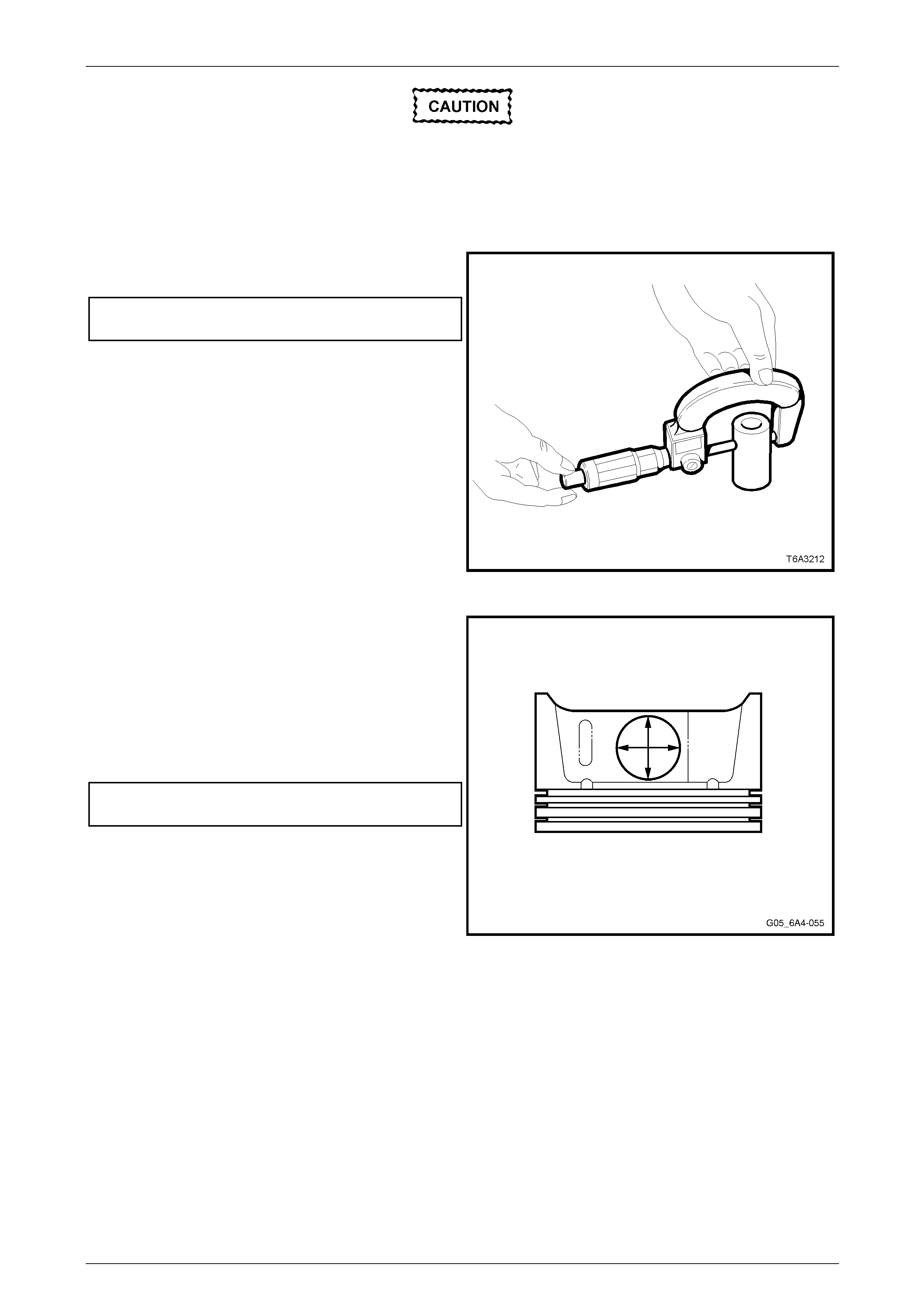
Engine Mechanical – HSV – Gen IV V8 Page 6A4–70
Page 6A4–70
For accuracy and to eliminate the
unnecessary replacement of parts, ensure
that for each of the following measurements
the micrometer used is reset to zero and the
measurements are all taken with components
at room temperature.
8 To measure the pin to bore clearance, first measure
the pin with a micrometer.
Piston pin diameter
Specification.................................. 23.997 – 24.000 mm.
Figure 6A4 – 127
9 Using a suitable inside micro m eter, measure the
matching piston pin bore in both directions on each
side of the piston. This is to ensure that the piston pin
bore has not worn unevenly.
10 Subtract the piston pin dimension from the piston pin
bore size to obtain the clearance.
11 If the clearance exceeds the specific ation, the piston
and pin assembly must be replaced.
Piston pin to bore clearance specific ation:
piston pin clearance (Maximum)........ 0.010 – 0.020 mm
Figure 6A4 – 128
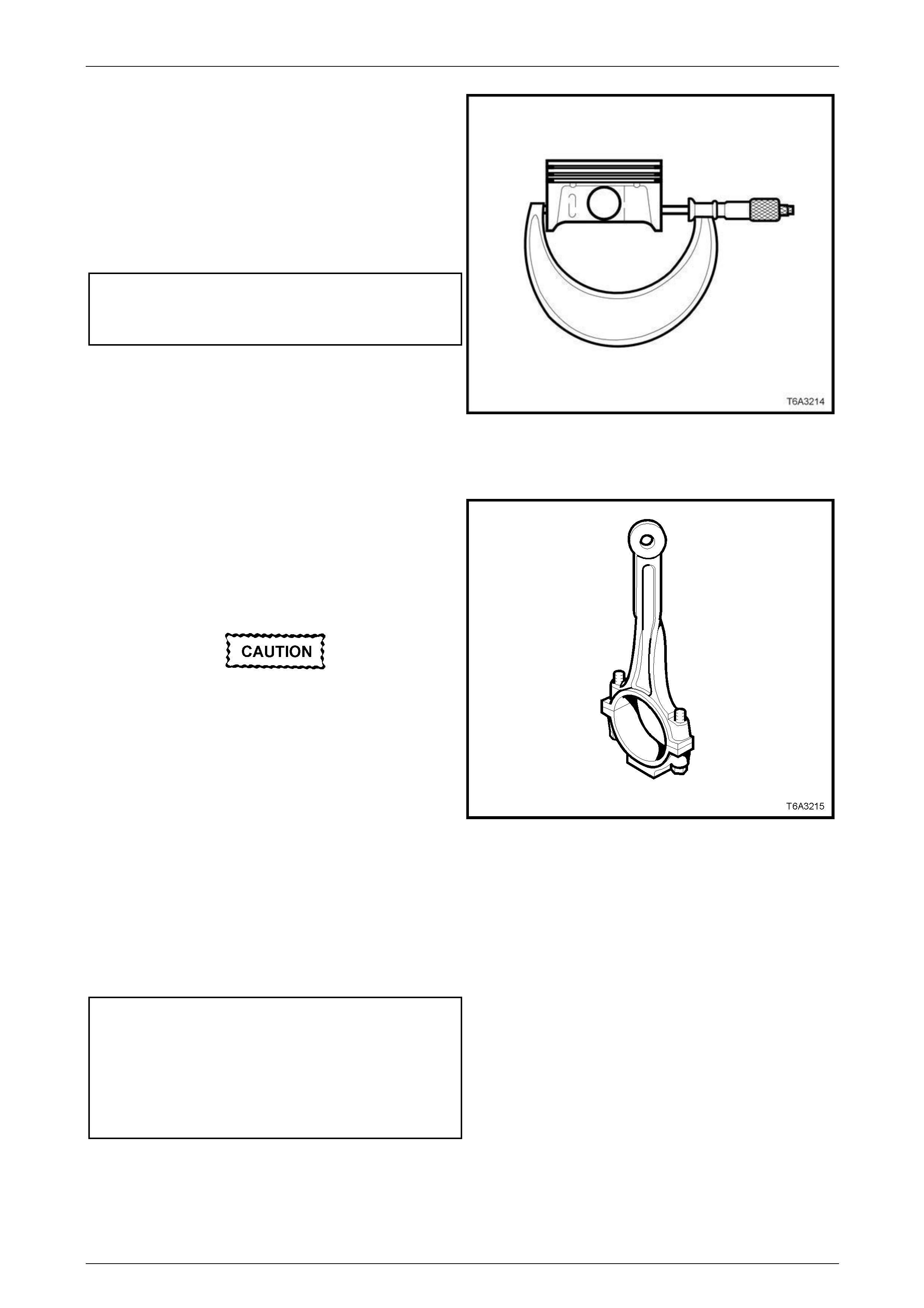
Engine Mechanical – HSV – Gen IV V8 Page 6A4–71
Page 6A4–71
12 Measure the piston for out-of-roundness as follows:
a With a suitable sized micrometer at right angles
to the piston pin bore, measure the piston skirt
dimension 11 mm above the bottom of the skirt.
b Measure the piston again at two different points,
then compare the readings.
c If the difference exceeds the specification, then
replace the piston and pin ass embly.
Piston skirt out-of round specification:
Piston skirt dimension
maximum variation.......................................... 0.018 mm
Figure 6A4 – 129
Connecting Rods and Bearings
1 Clean each connecting ro d and matching cap in a
commercially available cleaning fluid.
2 Clean the connecting rod bolt threads a nd inspect for
damage. Do not attempt to repair damaged threads in
this location. Replace the con necting rod, cap and
bolts as an assembly if thread damage is found.
Wear safety glasses w hen usin g compressed
air to avoid eye injury.
3 Blow the parts dry using compressed air.
4 Inspect the connecting rod for the following defects:
a Twisting, using commercially available alignment
equipment.
b Bending, check the lengt h with suitable
measuring equipment.
c Nicks or gouging in the bearing bore.
d Damage to the bearing locating slots in the
bearing bore.
e Correct fit of the connecting rod and cap mating
surfaces.
Connecting rod specification:
Centre to Centre Length .................... 154.90 ± 0.02 mm
Width.................................................... 24.00 ± 0.05 mm
Twist Maximum............................................... 0.010 mm
Bend Maximum................................................. 0.02 mm
Figure 6A4 – 130
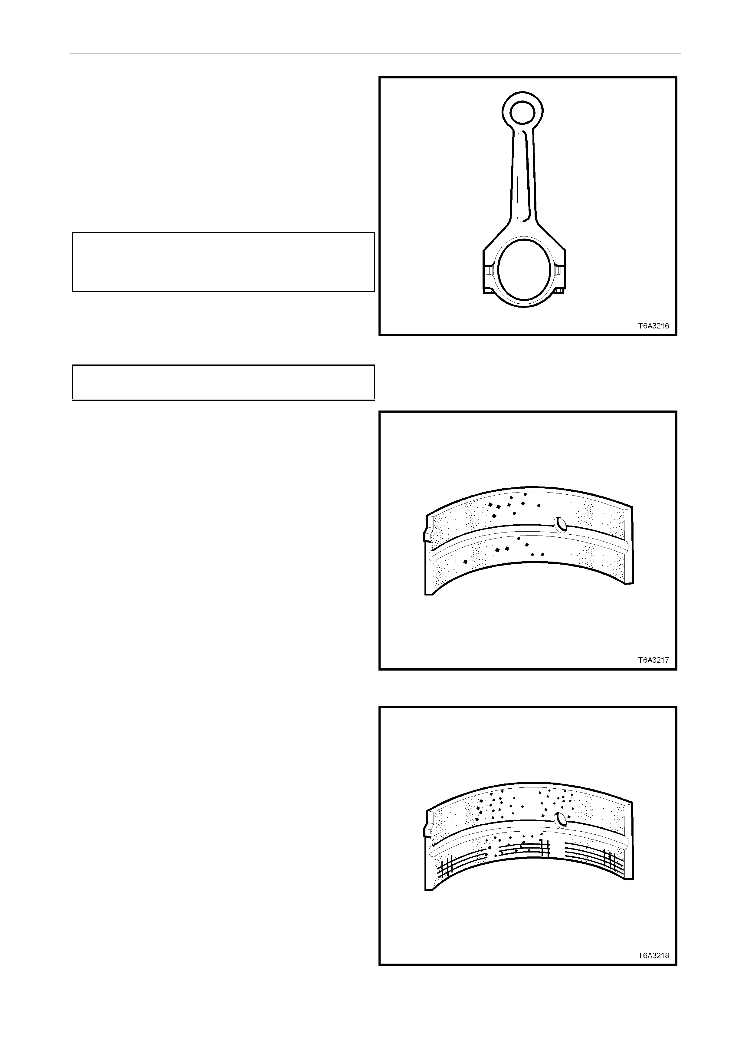
Engine Mechanical – HSV – Gen IV V8 Page 6A4–72
Page 6A4–72
5 Reinstall the connecting rod big end cap and bolts
without the bearings and tighten the bolts to the
correct torque specification.
NOTE
Used connecting rod bolts can be used for this
measurement, however the bolts are torque to
yield and must be replaced when final
reassembly of the connecting rod to the
crankshaft is performed.
Connecting rod cap bolt torque specific ation:
Stage 1: ................................................................20 Nm
Stage 2: ....................................................60° turn angle
6 Measure the connecting rod big end bore with a
suitable inside micrometer and check the b ore for out
of round. Replace any connecting rod assembly that
exceeds specification.
Connecting rod big end out-of round
maximum specification.................................... 0.008 mm
Figure 6A4 – 131
7 Inspect the connecting rod bearing halves for the
following:
a Craters or pockets and flattened sections on the
bearing halves, which also indicate fatigue.
Figure 6A4 – 132
b Excessive scoring or discolouration.
c Dirt or debris embedded into the bearing material
or backing metal.
Figure 6A4 – 133
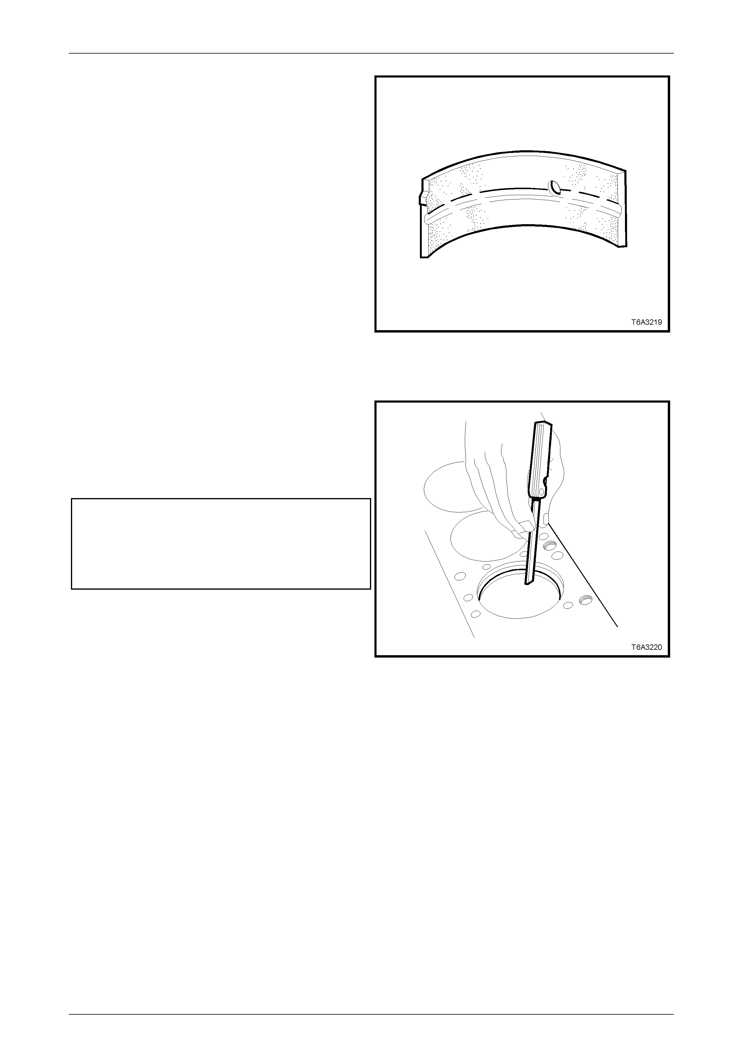
Engine Mechanical – HSV – Gen IV V8 Page 6A4–73
Page 6A4–73
d Improper seating indicated by bright polished
section/s on the bearing material.
Figure 6A4 – 134
Measuring Piston Ring End Gap
1 Insert a new piston ring into the bore that it is to be
fitted and push it down the bore using the piston
inverted until the ring is approximatel y 6.5 mm below
the piston ring top and bottom travel area.
2 Insert a feeler gauge and measure the piston ring end
gap. End gap specifications are as follows:
Piston ring end gap specifications:
Top compression ring .........................0.230 - 0.380 mm
Second compression ring ...................0.440 - 0.640 mm
Oil control ring.....................................0.180 - 0.690 mm
Figure 6A4 – 135
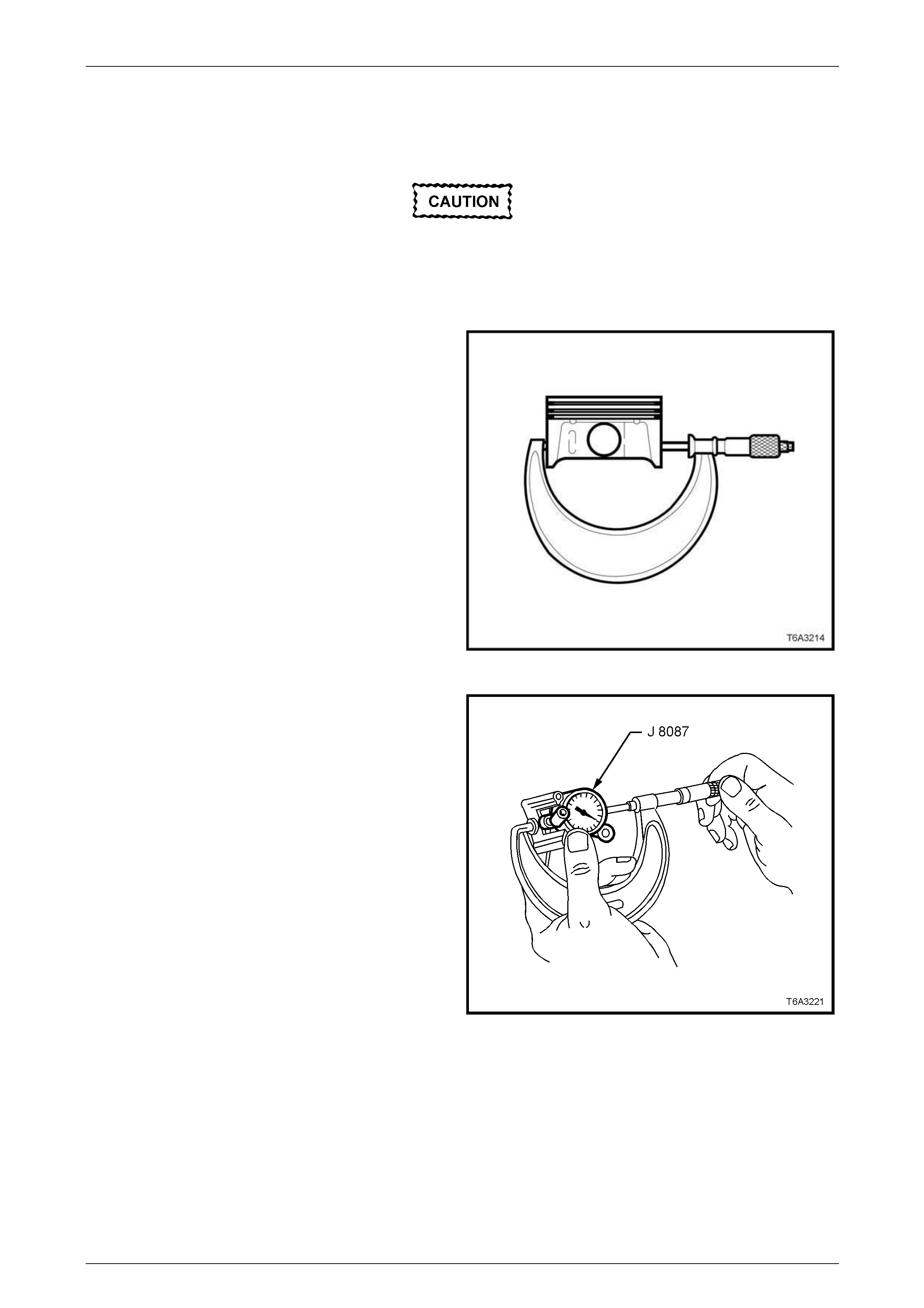
Engine Mechanical – HSV – Gen IV V8 Page 6A4–74
Page 6A4–74
Reassemble
Piston Selection
The cylinder bore must be checked for bore
out-of-round and taper before this operation
is attempted. Refer Section 6A3 Engine
Mechanical - 4.15 Cylinder Block in the
MY 2004 Holden VZ Service Information.
1 With a micrometer at right angles to the piston pin
bore, measure the piston skirt 11 mm up from the
lower edge. Record the piston diameter.
NOTE
All measurements should be taken at normal
room temperature. A used piston and pin set
may be reinstalled if, after cleaning and
inspection, they are both within specifications.
Figure 6A4 – 136
2 Ensure the micrometer is at the recorded piston
diameter.
3 Using a cylinder bore gauge, Tool No. J 8087 or
equivalent held between the micrometer anvils, zero
the dial indicator.
Figure 6A4 – 137
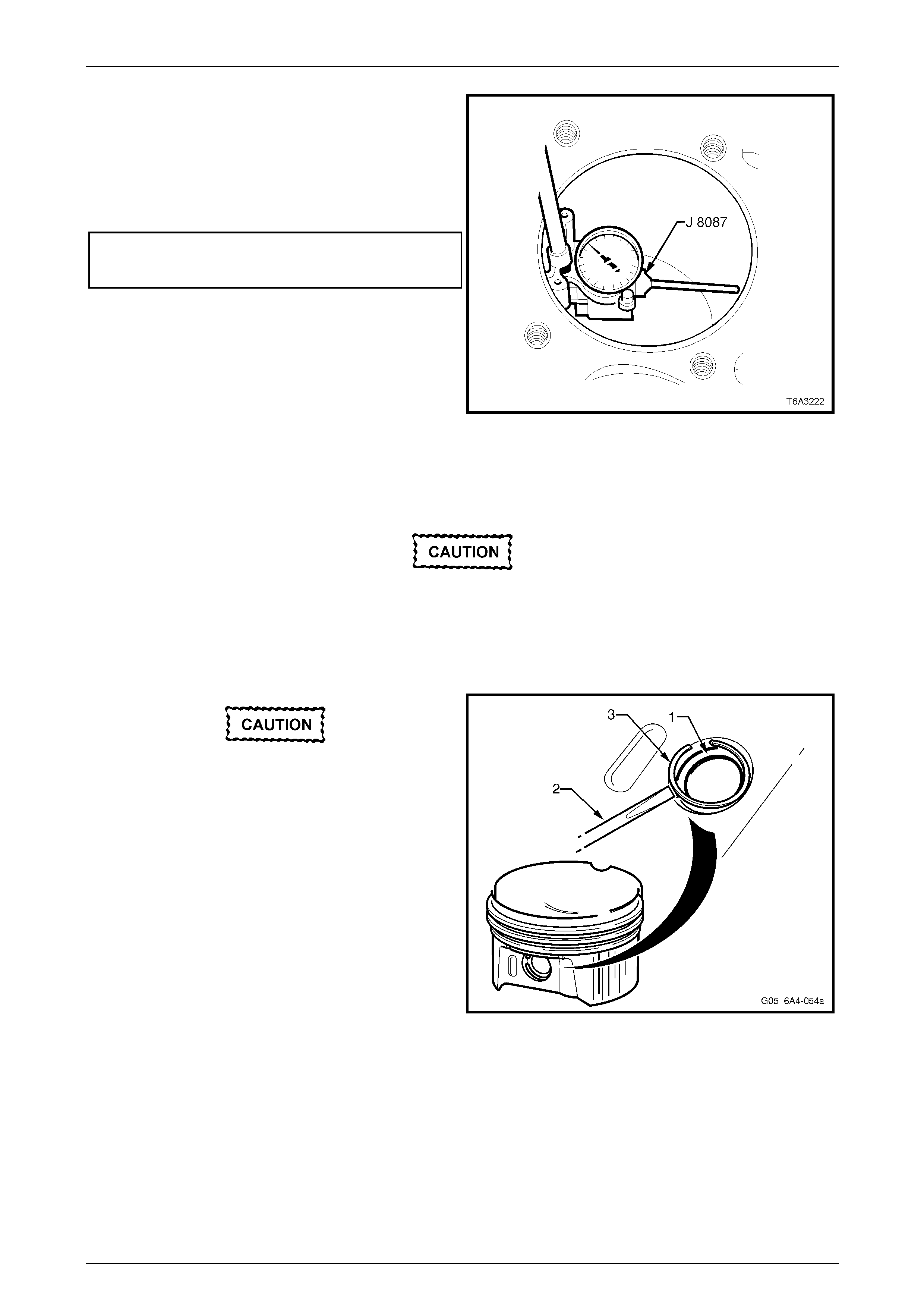
Engine Mechanical – HSV – Gen IV V8 Page 6A4–75
Page 6A4–75
4 Using a cylinder bore gauge, Tool No. J 8087 or
equivalent, measure the cylin der bore diameter at a
point 57 mm from the top of the bore and record the
cylinder bore diameter.
5 Subtract the piston diameter from the c ylinder bore
measurement in order to determine the piston to bore
clearance.
Piston to bore clearance spec ification.
Clearance range ................................ 0.018 – 0.054 mm
6 If the measured clearance is outside this specificati on,
select another piston. Measur e and re-calculate the
clearance. If the correct clearance cannot be obtai ned
using this method, then the cylinder bore may require
honing for fitment of an oversize piston or the cylinder
block will need to be replace d.
7 When the correct piston to bore clearance is obtained,
mark the piston crown with the bore number for correct
installation. Figure 6A4 – 138
Piston to Connecting Rod
Ensure when assembling the piston to the
connecting rod that the matching
components and their orientation is correct.
1 The connecting rod alignm ent should be with the flat portion of the bolt flange facing forward. Also, note that the
piston alignment mark has the correct orientation.
Ensure a new piston pin retaining circlip is
installed and it is correctly seated in the
groove. Circlip failure could result in major
engine damage resulting in the block being
destroyed beyond repair.
2 Lubricate the piston pin bore, connecting rod bore and
piston pin (1) with clean engine oil.
3 Using a suitable scre wdriver (2), carefully install a new
piston pin retaining circlip (3) into one side of the
piston.
4 Reinstall the piston pin into the piston and connecting
rod.
5 Install the remaining circlip into the piston.
NOTE
Ensure the piston is free to move on the pin and
the piston pin retaining circlip on both sides of
the piston are seated in the grooves correctly.
Figure 6A4 – 139
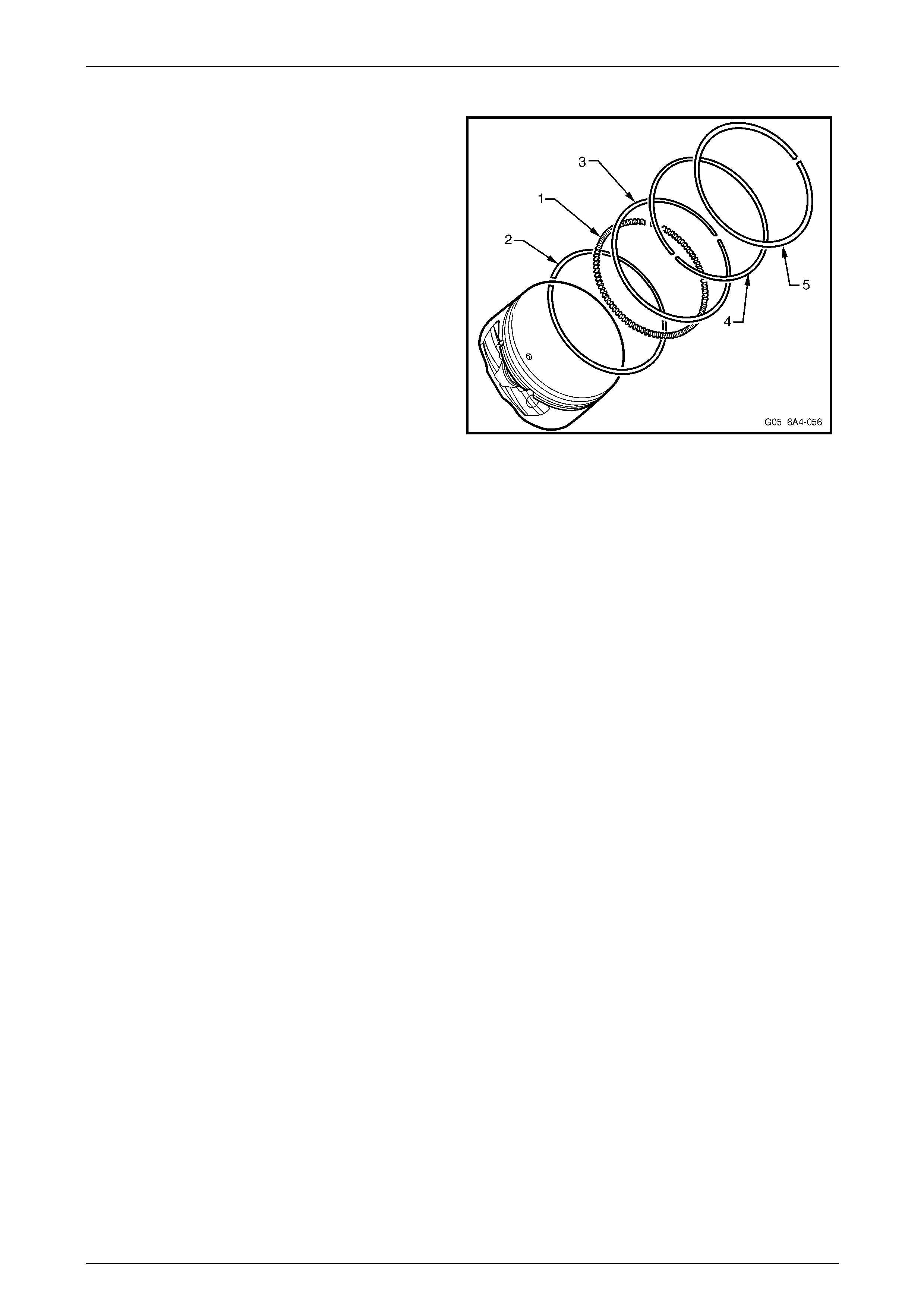
Engine Mechanical – HSV – Gen IV V8 Page 6A4–76
Page 6A4–76
Piston Rings
1 Install the piston rings onto each piston, in the
following manner:
a Install the oil control segment ring (1) into the
lower ring groove. Ensure that the ends do not
overlap.
b Install the lower oil control ring (2). There are no
identifying marks, indicating orientation, as this
ring may be installe d in either direction.
c Install the upper oil control ring (3) in a similar
manner.
d Stagger the ends of the three oil control ring
components by at least 90°.
e Install the second compression ring (4), noti ng
that the dimple or orientation mark must face
upwards to the piston crown.
f Install the top compression ring (5).
NOTE
This ring has no orientation marks and may be
installed in either direction.
g Stagger the compression ring gaps between 90°
and 180°.
NOTE
Use piston ring pliers and only expand the
piston ring sufficiently to go over the piston.
Excessive expansion will permanently distort
the piston ring.
Figure 6A4 – 140
Reinstall
1 Before installation of the piston and connecting rod assembly, check the following:
a The piston ring end gaps are staggered correctly.
b The piston has been assemb led to the correct connecting rod.
c The connecting rod is fitted in the correct orientation.
NOTE
The bearing oil clearance must be checked
before final installation of the connecting rod
caps, refer to Section 6A3 Engine Mechanical -
4.13 Crankshaft and Bearings in the MY 2004
Holden VZ Service Information.
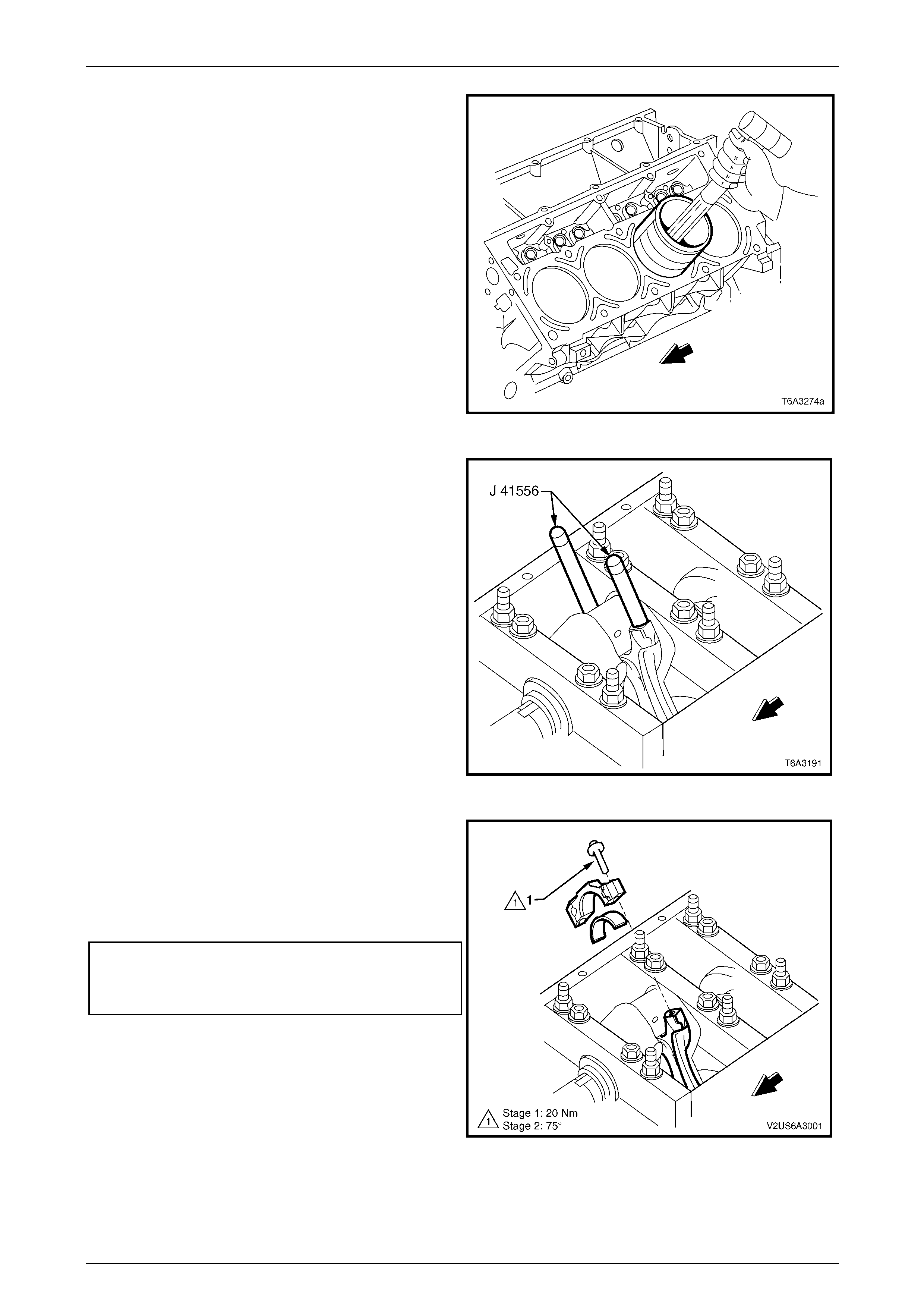
Engine Mechanical – HSV – Gen IV V8 Page 6A4–77
Page 6A4–77
2 Remove the connecting rod cap an d lower bearing
shell from the connecting rod being installed and
install the connecting rod guid e pins, Tool No.
J 41556.
3 Lightly lubricate the pisto n, cylinder bore, piston rings
and bearing surfaces with clean engine oil.
4 Install a piston ring compressor over the piston rings
and compress the rings.
5 Install the piston and connecti ng rod assembly into the
correct cylinder bore, ensuring that the piston
alignment mark is facing the front of the engine.
6 While holding the piston rin g compressor squarely and
firmly against the engine block, gently tap the piston
into the bore using a wooden hammer handle until all
piston rings have entered the bore.
7 Complete the installation by us ing the guide pins, Tool
No. J 41556 to guide the connecting rod onto the
crankshaft journal. Figure 6A4 – 141
8 Remove the connecting rod g uid e pins and check that
the upper bearing shell is corr ectly installed in the
connecting rod. Apply clean e ngine oil to the upper
bearing shell.
Figure 6A4 – 142
9 Install the lower connecting rod bear ing into the cap,
lubricate with clean engin e oil and install, ensuring that
the cap orientation is correct.
10 Install the new connecting rod bearing cap bolts and
tighten in two stages to the correct torque
specification.
Connecting rod bearing cap bolt torque specification
Stage 1 ..............................................................20.0 Nm
Stage 2 ....................................................75° turn angle.
NOTE
Use a torque angle meter, Tool No. E7115 or
equivalent to achieve the second reading.
Figure 6A4 – 143
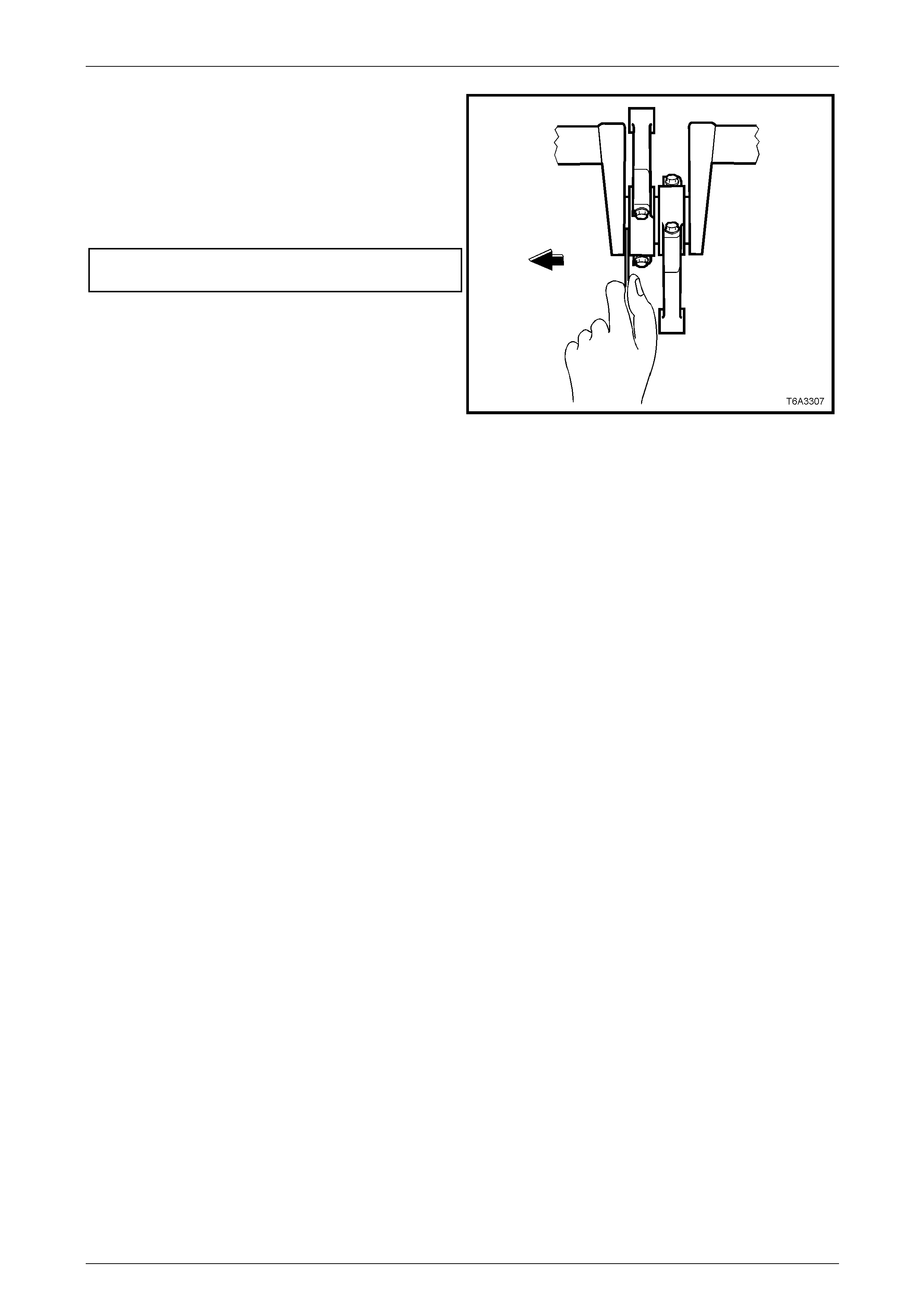
Engine Mechanical – HSV – Gen IV V8 Page 6A4–78
Page 6A4–78
11 With a pair of connecting rods installed onto the same
crankshaft journal, use a plastic faced hammer to
lightly tap each connecting rod sideways to settle and
measure the side clearance.
12 Using feeler gauges measure the connecting rod side
clearance by placing the feeler gauge in between the
connecting rod and the crankshaft journal. Ensure the
clearance is to specification.
Connecting rod side clearance
specification........................................... 0.11 – 0.51 mm
NOTE
If side clearance is insufficient, re-check bearing
oil clearance and/or connecting rod a lignment.
13 Reinstall the following:
a Oil pump screen and deflector, refer to
Section 6A3 Engine Mechanical -
4.9 Oil Pump, Pump Screen and Deflector in the
MY 2004 Holden VZ Service Information.
b Oil pan, refer to Section 6A3 Engine Mechanical
- 4.3 Oil Pan Assembly , Except AWD in the
MY 2004 Holden VZ Service Information.
c Cylinder heads, refer to
2.4 Cylinder Head Assembly.
Figure 6A4 – 144
Engine Mechanical – HSV – Gen IV V8 Page 6A4–79
Page 6A4–79
4 Specifications
General
Engine Type V8 OHV
Displacement 6.0 litre (5,967 cm3 – 364 in3)
Bore 101.6 mm
Stroke 92.0 mm
Compression Ratio 10.9:1
Spark Plug Type:
Gap:
AC Delco 41-985
1.02 +0.08 / -0.07 mm
Cylinder Layout
Firing Order 1-8-7-2-6-5-4-3
Left-hand bank
Right-hand bank
1, 3, 5, and 7
2, 4, 6 and 8
Camshaft
End Play 0.025 –- 0.305 mm
Journal Diameter 54.99 – 55.04 mm
Journal Diameter Out-of-round 0.025 mm (Maximum)
Lobe Lift: Intake
Exhaust
7.78 mm
7.78 mm
Lobe Height Minimum Intake
Exhaust
46.33 mm
46.33 mm
Runout (Measured at the Intermediate Journals) 0.050 mm
Cylinder Bore
Cylinder Bore Diameter 101.6 mm
Cylinder Bore Taper and Out-of-round 0.018 mm (maximum)
Engine Mechanical – HSV – Gen IV V8 Page 6A4–80
Page 6A4–80
Piston
Piston Outside Diameter (at size point & incl. coating) 98.995 – 99.027 mm
Piston Skirt, Dimensional Variation 0.032 mm (maximum)
Piston to Bore Clearance (Production)
Interference
Clearance
0.027 mm
0.023 mm
Piston to Bore Clearance ( S ervice Limit)
Interference
Clearance
0.027 mm
0.023 mm
Piston Pin
Pin Clearance to Piston Bore (prod uction) 0.008 – 0.016 mm
Pin Clearance to Piston Bore (service limit) 0.008 – 0.016 mm (maximum )
Pin Diameter 23.997 – 24.0 mm
Pin Fit in Connecting Rod 0.020 – 0.043 mm (interference)
Piston Rings
Top Compression Ring En d Gap (production)
(measured in cylinder bore) 0.230 – 0.380 mm
2nd Compression Ring End Gap (production)
(measured in cylinder bore) 0.440 – 0.640 mm
Oil Control Ring End Gap (production)
(measured in cylinder bore) 0.180 – 0.690 mm
Top Compression Ring En d Gap (service)
(measured in cylinder bore) 0.230 – 0.380 mm (maximum)
2nd Compression Ring End Gap (service)
(measured in cylinder bore) 0.440 - 0.640 mm (maximum)
Oil Control Ring End Gap (service)
(measured in cylinder bore) 0.230 – 0.380 mm (maximum)
Top Compression Ring Groove Clearance (production) 0.040 – 0.085 mm
2nd Compression Ring Groove Clearance (production) 0.040 – 0.080 mm
Oil Control Ring Groove Clearance (production) 0.010 – 0.220 mm
Top Compression Ring Groove Clearance (service) 0.040 – 0.085 mm (maximum)
2nd Compression Ring Groove Clearance (service) 0.040 – 0.080 mm (maximum)
Oil Control Ring Groove Clearance (service limit) 0.010 – 0.220 mm (maximum )
Engine Mechanical – HSV – Gen IV V8 Page 6A4–81
Page 6A4–81
Valve System
Valve Lifter Hydraulic Roller
Valve Rocker Arm Ratio 1.70:1
Valve Lash Net Lash – No Adjustment
Valve Margin 1.25 Minimum
Valve Face Angle 45 degrees
Valve Seat Angle 46 degrees
Valve Seat
Runout 0.050 mm (maximum)
Width (intake) 0.050 mm (maximum)
Width (exhaust) 1.020 mm (maximum)
Valve Stem
Clearance (production-intake) 0.025 – 0.066 mm
Clearance (production – exhaust) 0.025 – 0.066 mm
Clearance (service-intake) 0.093 mm (maximum)
Clearance (service – e xhaust) 0.093 mm (maximum)
Diameter (production) 7.955 – 7.976 mm
Diameter (service) 7.95 mm (minimum)
Valve Spring
Free Length 52.9 mm
Pressure (closed valve) 340 N at 45.75 mm (minimum)
Pressure (open valve) 980 N at 33.55 mm (minimum)
Installed Height (intake) 45.75 mm
Installed Height (exhaust) 45.75 mm
Valve Lift
Intake 11.83 mm
Exhaust 12.11 mm
Valve Guide Installed Height
(from cylinder head spring seat surface to top of the valve
guide) 17.32 mm

Engine Mechanical – HSV – Gen IV V8 Page 6A4–82
Page 6A4–82
5 Torque Wrench Specifications
ATTENTION
All engine fasteners are important attaching parts as they affect th e performance of vital componen ts and/or
could result in majo r repair expense. Where specified in this Section, fasteners MUST be rep laced with parts
of the same part number or a GM approved equivalent. Do not use fasteners of an inferior quality or
substitute design.
Torque values must be used as specified during reassembly to ensure proper retention of all engine
components.
Through out this Section, fastener torque wrench specifications may be accompanied with the following
Identification marks:
Fasteners must be repl aced after loosening.
Fasteners either ha ve micro encapsulated sealan t applied or incorp orate a mechanical th read lock and
should only be re-used once. If in doubt, replacement is recommended.
If one of these identification marks is present alongside a fastener torque wrench specification, the
recommendation regarding that fastener must be adhered to.
EVAP Purge Valve Bracket Attaching Bolt....................................4.0 – 6.0 Nm
Fuel Rail Attaching Studs............................................................8.0 – 12.0 Nm
Throttle Body Bolts...............................................................................12.0 Nm
Intake Manifold Bolts (in Sequence)
Stage 1 ..................................................................................................5.0 Nm
Stage 2........................................................................................8.0 – 12.0 Nm
Valley Cover Bolts.....................................................................20.0 – 35.0 Nm
Valve Rocker Arm Cover Attaching Bolt...............................................12.0 Nm
Ignition Coil to Mounting Bracket Bolts.................................................12.0 Nm
Ignition Coil Mounting Bracket Fastener......................................8.0 – 12.0 Nm
Automatic Transmission Dipstick Tube Attaching Bolt..........................30.0 Nm
Power Train Harness Ground Strap
(front of cylinder head) Attaching Bolt .........................................5.0 – 12.0 Nm
Power Train Harness Ground Strap
(rear of the cylinder head) Attaching Bolt ....................................5.0 – 12.0 Nm
♦ Temperature Sender........................................................................20.0 Nm
♦ Right-hand Cylinder Head Core Plug....................................15.0 – 25.0 Nm
Cylinder Head Bolts (in Seque nce)
Stage 1 – all M11 and M8 Bolts............................................................30.0 Nm
Stage 2 – all M11 Bolts................................................90 degrees turn angle
Stage 3 – M11 Bolts........................................................90 degrees turn angle
Spark Plug
New Cylinder Head ..............................................................................20.0 Nm
Used Cylinder Head .............................................................................15.0 Nm

Engine Mechanical – HSV – Gen IV V8 Page 6A4–83
Page 6A4–83
Oil Pan Drain Plug................................................................................25.0 Nm
High Pressure Power Steering Bracket to
Oil Pan Attaching Bolt................................................................20.0 – 30.0 Nm
Rear Crossmember to Vehicle Attaching Bolt ......................................58.0 Nm
Rear Crossmember to Mount Attaching Nut.........................................25.0 Nm
Rear Mount to Transmission Exte nsion Housing
Attaching Bolt............................................................................30.0 – 50.0 Nm
Engine Front Cover Bolts .....................................................................25.0 Nm
Camshaft Position Sensor Bolt.............................................................25.0 Nm
Front Cover Alignment Tool Attaching Bolt...........................................25.0 Nm
Camshaft Gear Attaching Bolt...................................................30.0 – 35.0 Nm
Timing Chain Dampener Attaching Bolt.....................................30.0 – 40.0 Nm
Camshaft Retainer Attaching Bolt ........................................................25.0 Nm
Connecting rod bearing cap bolt
Stage 1.................................................................................................20.0 Nm
Stage 2........................................................................................75° turn angle