
Engine Cooling – HSV – Gen IV V8 Page 6B4–1
Page 6B4–1
Section 6B4
Engine Cooling – HSV - Gen IV V8
ATTENTION
Before performing any service operation or other procedure described in this Section, refer to Section 00
Warnings, Cautions and Notes for correct workshop practices with regard to safety and/or property damage.
1 General Information ...............................................................................................................................2
1.1 General Description............................................................................................................................................... 2
Radiator .................................................................................................................................................................. 2
Cooling Fans.......................................................................................................................................................... 2
Operation ........................................................................................................................................................... 4
Coolant Pump......................................................................................................................................................... 9
Thermostat ........................................................................................................................................................... 10
Radiator Pressure Cap ........................................................................................................................................ 11
Coolant Overflow Reservoir................................................................................................................................ 11
Vapour Vent System............................................................................................................................................ 12
Air Baffles and Ducts........................................................................................................................................... 12
Coolant Temperature Sensor.............................................................................................................................. 12
2 Service Operations...............................................................................................................................13
2.1 Service Notes....................................................................................................................................................... 13
Safety.................................................................................................................................................................... 13
Periodic Servicing................................................................................................................................................ 13
Environmental Issues.......................................................................................................................................... 13
2.2 Coolant Maintenance........................................................................................................................................... 14
Topping-up Cooling System............................................................................................................................... 14
2.3 Draining and Filling Cooling System ................................................................................................................. 15
Draining ................................................................................................................................................................ 15
Filling.................................................................................................................................................................... 15
2.4 Coolant Hoses...................................................................................................................................................... 16
2.5 Cleaning Cooling System.................................................................................................................................... 18
Cooling System Reverse Flush .......................................................................................................................... 18
Radiator............................................................................................................................................................ 18
Engine.............................................................................................................................................................. 19
Heater Hoses and Core.................................................................................................................................... 19
2.6 Pressure Testing.................................................................................................................................................. 20
3 Engine Cooling System Diagnostics..................................................................................................21
3.1 Engine Overheating............................................................................................................................................. 21
Definition .............................................................................................................................................................. 21
3.2 Loss of Coolant.................................................................................................................................................... 23
Definition .............................................................................................................................................................. 23
3.3 Engine Fails to Reach Normal Operating Temperature.................................................................................... 25
4 Specifications.......................................................................................................................................26
5 Torque Wrench Specifications............................................................................................................28
6 Special Tools ........................................................................................................................................29

Engine Cooling – HSV – Gen IV V8 Page 6B4–2
Page 6B4–2
1 General Information
The cooling system for MY 2005 HSV VZ Series vehicles differs from that used on previo us models.
Two fans driven by dual-speed electric motors are still used and both motors operate in each of the two stages, but the
lower speed (stage 1 operatio n) is obtained by connecting the t wo motors in series.
Operation of the cooling fans is still dependent on engine coolant tempera ture, vehicle speed, A/C request (where fitted)
and A/C system pressure. Refer to Section 6C3 Engine Management – GEN III V8 for further information.
Also dependent on vehicl e specification, is the type of coolant used. As requir ements can change, always refer to the
MY 2005 HSV VZ Series Owner’s Handbook for specific information regarding the particular vehicle being serviced.
1.1 General Description
Radiator
The radiator utilises an aluminium core and is of the cross-flow design, with a radiator cap locate d on the right-hand side
tank. Plastic side tanks are attached to the core by the use of clinch tabs. The clinch tabs are formed as part of the core
assembly.
For vehicles with automatic transmission, a transmission oil cooler is l ocated in the right-hand side radi ator tank. The
cooler pipes to and from the transmission are connected to the oil cooler flexible hoses by means of quick connect
fittings.
NOTE
The radiator core side tanks and transmission
oil cooler are not separ ately serviced. If there is a
fault with any of these components, the
radiator assembly must be replaced.
Minor repairs to the core may be made using
an aluminised silicon-based liquid repair agent,
refer to Section 6B3 Engine Cooling -
3.15 Radiator – Radiat or Repair Procedure in the
MY 2004 Holden VZ Series Service Informat ion.
When air conditioning is fitted, an air conditioning condens er is mounted, by means of clips and brackets, to the front of
the radiator. The air conditioning filter drier receiver also forms a part of the complete assembly.
Pegs are attached to the lower frame and the upper area of each side tank. These pegs are used to support the radiator
in four rubber mounts. The assembly is hel d in position by two spring clips at the upper mounting locati ons.
Cooling Fans
In order to achieve their function of transferring heat from the fluids in them, the radiator a nd air conditioning condenser
require an air flow through them. For much of the time the forward movement of the vehicl e will provide adequate air flow
but to ensure sufficient air flow under all operating conditions, two electric motor driven fans are fitted. The fan and motor
assemblies are mounted on a common shroud which is attached to the engine side of the radiator. The assembly of the
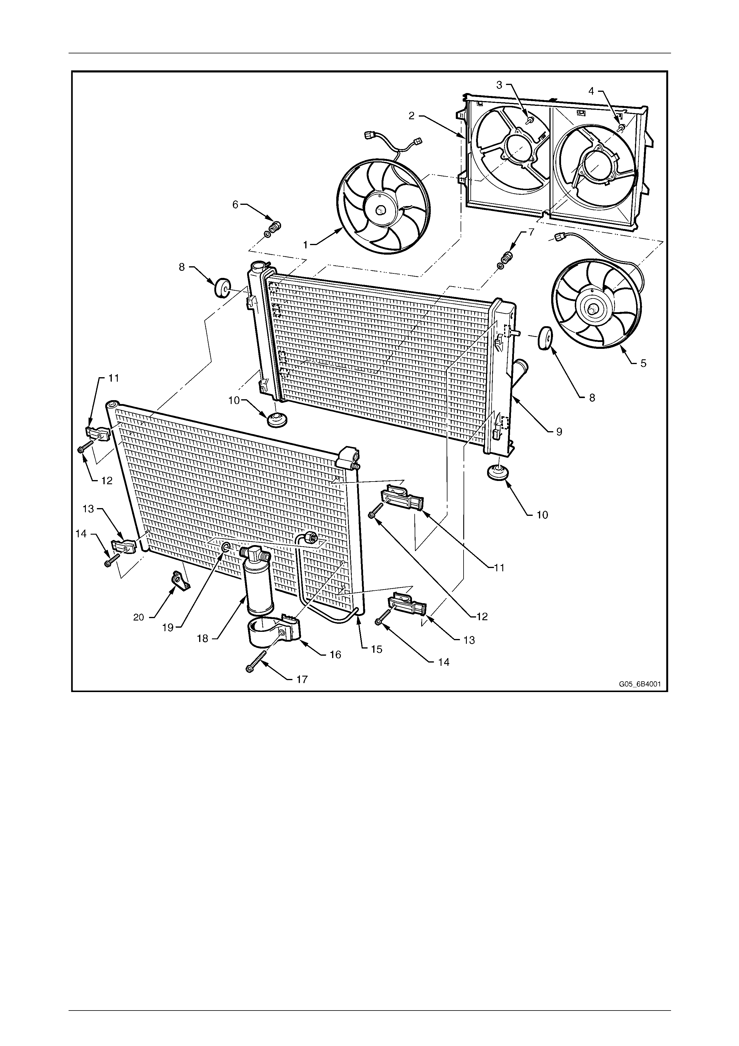
condenser, radiator, cooling fans and fan motors is referred to as the Condenser, Radiator and Fan Modu le (CRFM) and
an exploded view of this module is shown in Figure 6B4 – 1.
Engine Cooling – HSV – Gen IV V8 Page 6B4–3
Page 6B4–3
Figure 6B4 – 1
Legend
1 RHS Fan and Fan Motor Assembly
2 Fan Shroud
3 RHS Fan Retaining Screw (3 places)
4 LHS Fan Retaining Screw (3 places)
5 LHS Fan Retaining Screw (3 places)
6 Inlet Transmission Cooling Line Connector / O-ring
7 Outlet Transmission Cooling Line Connector / O-ring
8 Upper Radiator Insulators (2 places)
9 Radiator
10 Lower Radiator Insulators (2 places)
11 Upper Condenser Mounting Clips (2 places)
12 Upper Condenser Mounting Clip Screws (2 places)
13 Lower Condenser Mounting Clips (2 places)
14 Lower Condenser Mounting Clip Screws (2 places)
15 Condenser
16 Filter Drier Receiver Mounting Bracket
17 Filter Drier Receiver Mounting Bracket Screw
18 Filter Drier Receiver
19 O-ring
20 Ambient Air Temperature Sensor Mounting Bracket
Engine Cooling – HSV – Gen IV V8 Page 6B4–4
Page 6B4–4
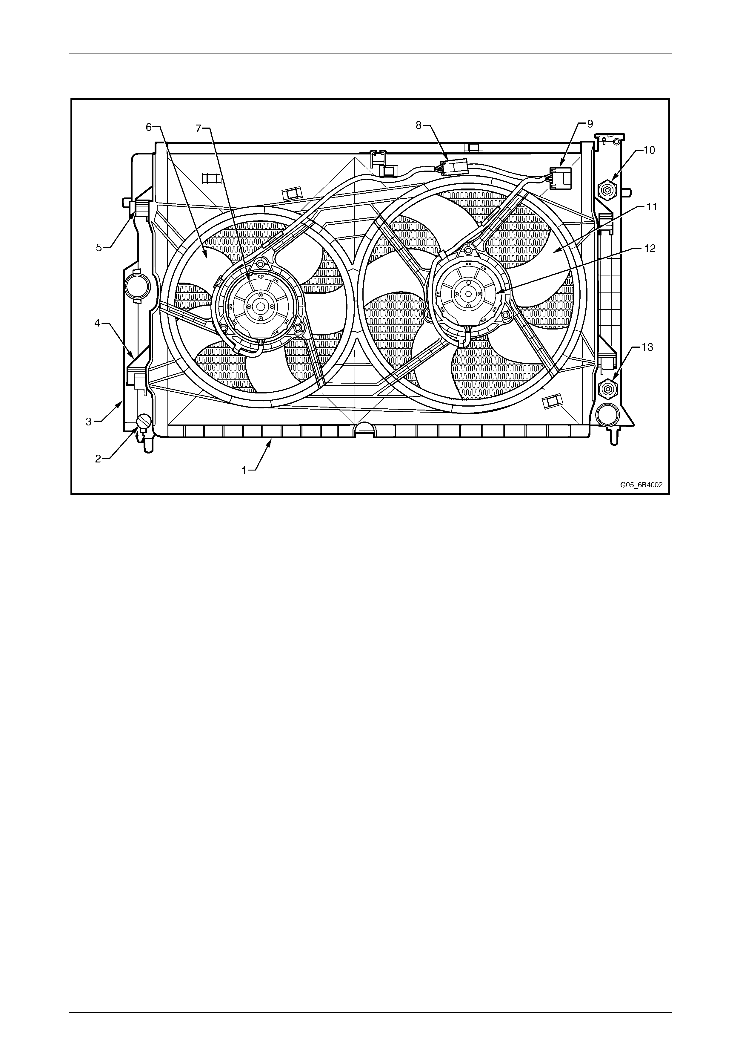
The general arrang ement of the fans and motors is shown in Figure 6B4 – 2.
Figure 6B4 – 2
Legend
1 Fan Shroud
2 Radiator
3 Fan Shroud Lower Support
4 Fan Shroud Upper Support / Locking Retainer
5 Small (left) Fan
6 Small (left) Fan Motor
7 Left Fan Motor Harness Connector (2 Terminal)
8 Left and Right Fan Motors Harness Connector (4 Terminal)
9 Large (Right) Fan
10 Large (Right) Fan Motor
11 Oil Cooler Lower Quick Connect Fitting (Auto Trans. Only)
12 Oil Cooler Upper Quick Connect Fitting (Auto Trans. Only)
Operation
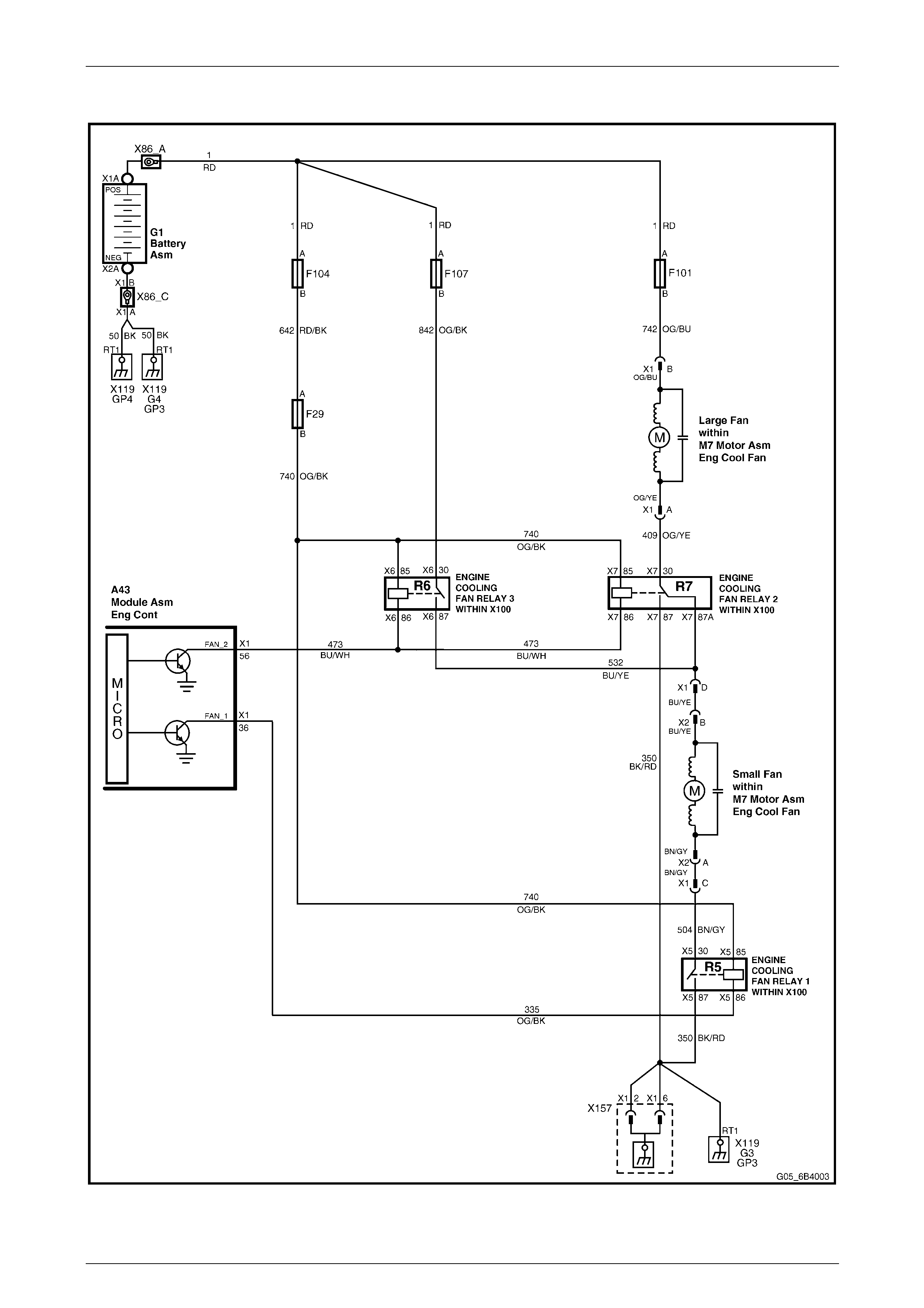
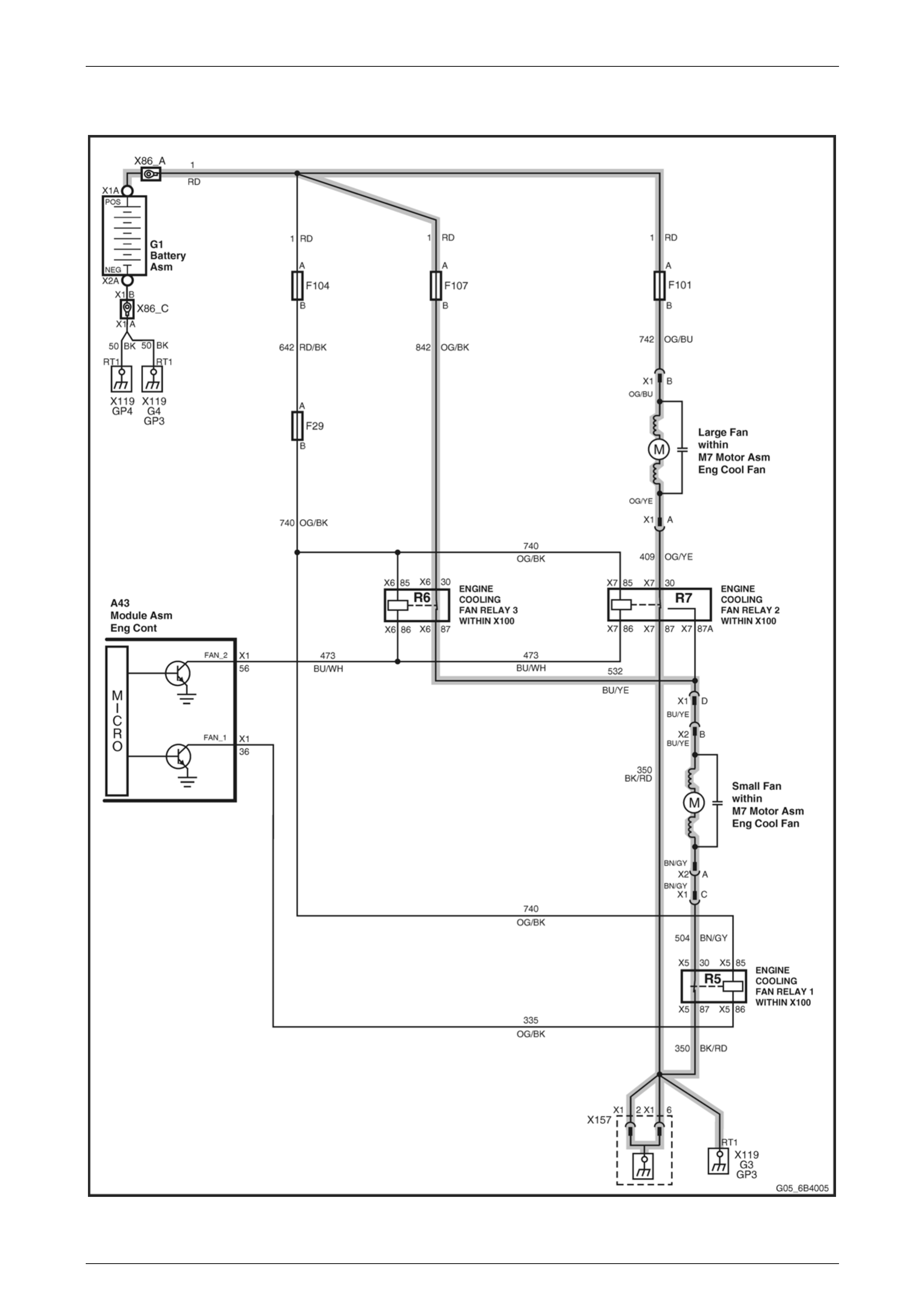
The cooling fans operate in two stages; in both stages both fans run. In stage 1 the two fan motors are connected in
series so both fans run at low speed. In stage 2 each fan motor is connected to battery supply so both fans run at high
speed. The fan circuit wiring is shown in Figure 6B4 – 3.
Cooling fan operation is controlled by the Engine Control Module (ECM) based on inputs from the Occupant Climate
Control (OCC) Module (A/C request signal via the serial data bus, Powertrain Interface Module and GM LAN bus), the
Vehicle Speed Sensor (VSS), the A/C refrigerant pressure transducer and the Engine Coolant Temperatu r e (ECT)
Sensor.
Engine Cooling – HSV – Gen IV V8 Page 6B4–5
Page 6B4–5
Figure 6B4 – 3
Engine Cooling – HSV – Gen IV V8 Page 6B4–6
Page 6B4–6
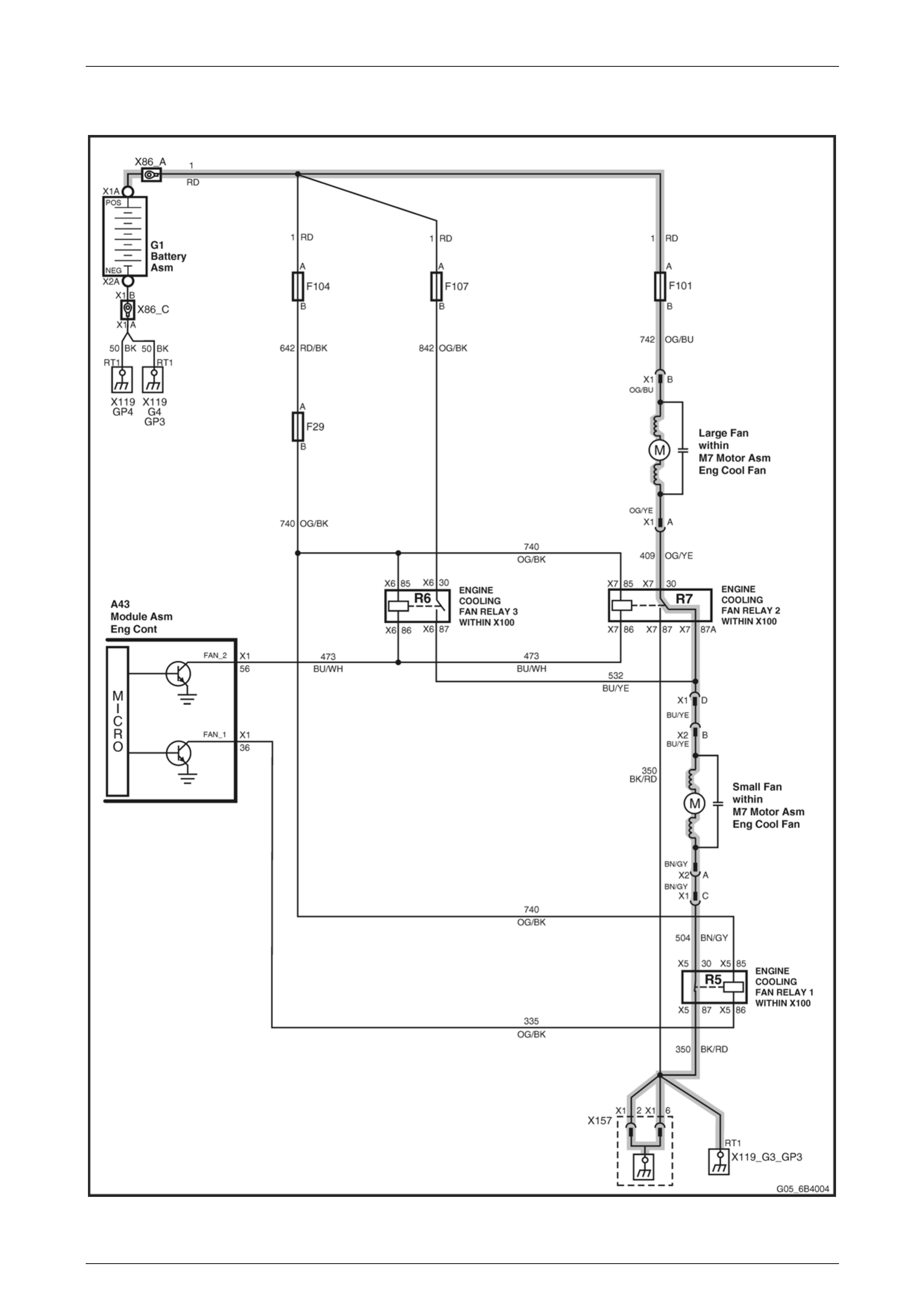
Stage 1
Figure 6B4 – 4

Engine Cooling – HSV – Gen IV V8 Page 6B4–7
Page 6B4–7
The ECM determines when the engine cooling fans should operate at stage 1 (i.e. engine cooling fan relay 1 is e nergised
and both fans, being connected in series, run at low speed) based on inputs from the A/C request signal, Vehicle Speed
Sensor (VSS) and the Engine Coolant Temperature (ECT) sensor. When the conditions for stage 1 operation are met the
ECM provides a ground to the coil of engine cooling fan relay 1 (R5), ca using it to operate (turn ON); the fan current path
is then from the battery via fusible link F101, through the large fan motor, cooling fan relay 2 (R7), the small fan motor
and cooling fan relay 1 (R5) to ground.
The conditions for Stage 1 operation are:
(a) There is an A/C request and:
• the vehicle speed is less than 30 km/h or;
• the A/C refrigerant pressure is greater than 1500 kPa or;
(b) The engine coolant temperature is greater than 98 °C or;
(c) The engine coolant temperature is greater than 113 °C when the engine is switched off (in this case stage 1
will operate for approximately four minutes – this is referred to as low fan run-on) or;
(d) An ECT sensor fault is detected and a DTC such as P0117, P0118, P1114 or P1115 is set.
Stage 1 operation will cease when:
(a) There is no A/C request and the engine coolant temperature is less than 95 °C or;
(b) There is an A/C request and the vehicle sp eed is greater than 50 km/h and the A/C pressure is less than
1170 kPa and the engin e coolant temperature is less than 95 °C or;
(c) The vehicle speed is greater than 104 km/h.
Engine Cooling – HSV – Gen IV V8 Page 6B4–8
Page 6B4–8
Stage 2
Figure 6B4 – 5
Engine Cooling – HSV – Gen IV V8 Page 6B4–9
Page 6B4–9
The ECM also determines when the engine cooling fans should operate at stage 2 (i.e. engine cooling fan rel ays 1, 2 and
3 are energised and both fans, each being connected to battery suppl y, run at high speed) based on inputs from the A/C
request signal, Vehicle Speed Sensor (VSS) and the Engine Coolant Temperature (ECT) sensor. When the conditions
for stage 2 operation are met the ECM prov ides – in addition to that already provided for the coil of engi ne cooling fan
relay 1 (R5) – a ground to the coils of engine cooling fan relays 2 and 3 (R7 and R6), causing them to operate (turn ON).
For the large fan the current path is then from the battery via fusible link F101, throu gh the large fan motor and engine
cooling fan relay 2 (R7) to gro und. For the small fan the current path is from the battery via fusible link F107, throu gh
engine cooling fan relay 3 (R6), through the small fan motor and engine cooling fan rela y 1 (R5) to ground.
The conditions for stage 2 operation are:
(a) The A/C refrigerant pressure is greater than 2400 kPa or;
(b) The engine coolant temperature is greater than 108 °C or;
(c) An ECT sensor fault is detected and a DTC such as P0117, P011 8, P1114 or P1115 is set.
(d) There is a BCM message response fault, which will cause a PIM DTC B2002 to set.
If stage 1 operation is off when the condition s for stage 2 operation are met, stage 2 operation will be initiated 5 s after
initiation of stage 1 operation.
Stage 2 operation will cease and re vert to stage 1 operation when:
(a) The engine coolant temperature is less than 102 °C and;
• there is no A/C request or;
• there is an A/C request and the A/C refrigerant pressure is less than 1900 kPa or;
(b) The vehicle speed is greater than 104 km/h.
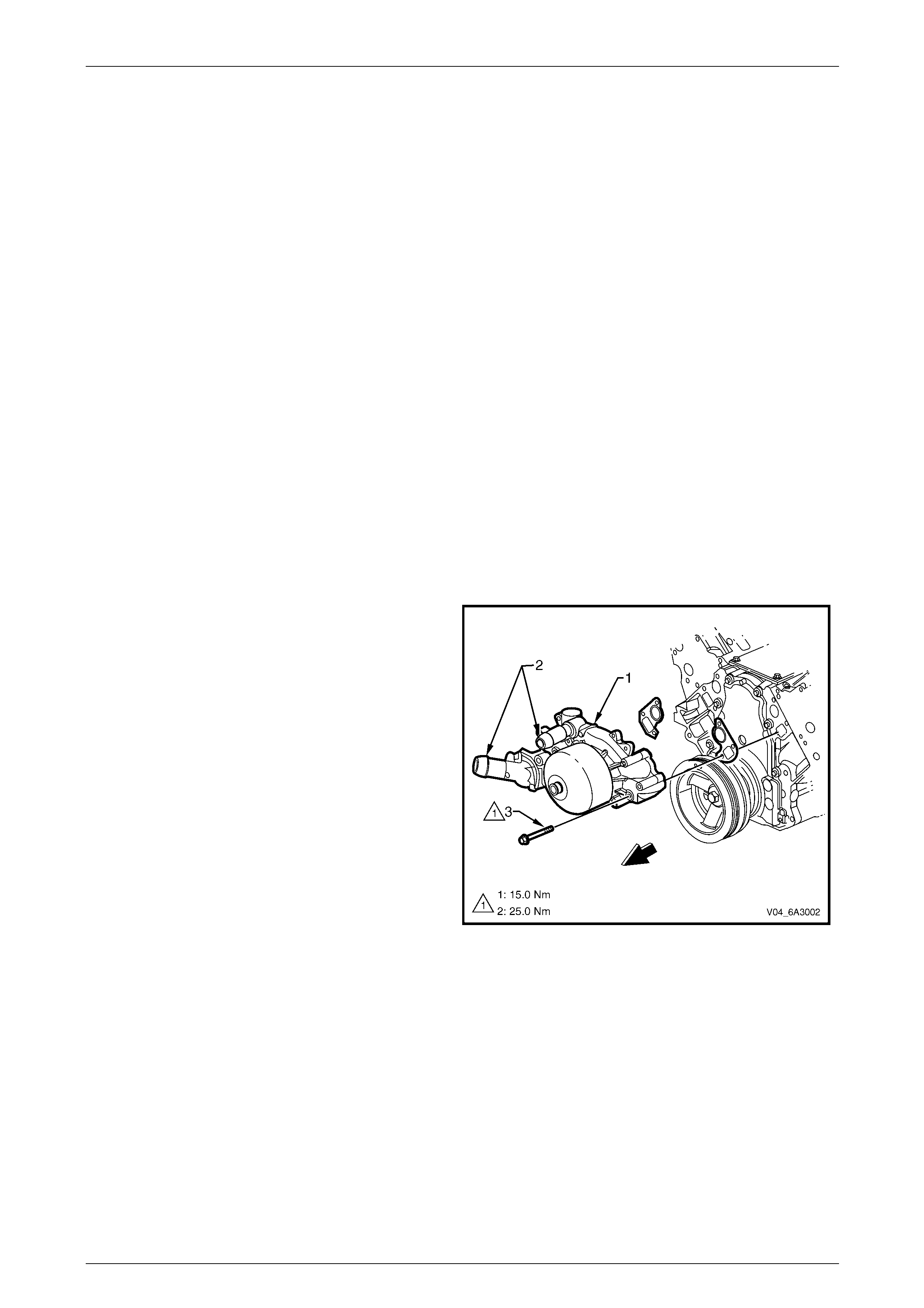
Coolant Pump
The length of the coolant pump (1) inlet and outlet tubes
(2) has been extended for easier coolant h ose installation
and to improve the fit of the hose to the pump.
NOTE
The changes to the coolant pump design do
not affect the pump service procedure. For
water pump service procedure refer to
Section 6B3 Engine Cooling – GEN III V8 in
the MY 2004 Holden VZ Series Service
Information.
Figure 6B4 – 6
Engine Cooling – HSV – Gen IV V8 Page 6B4–10
Page 6B4–10
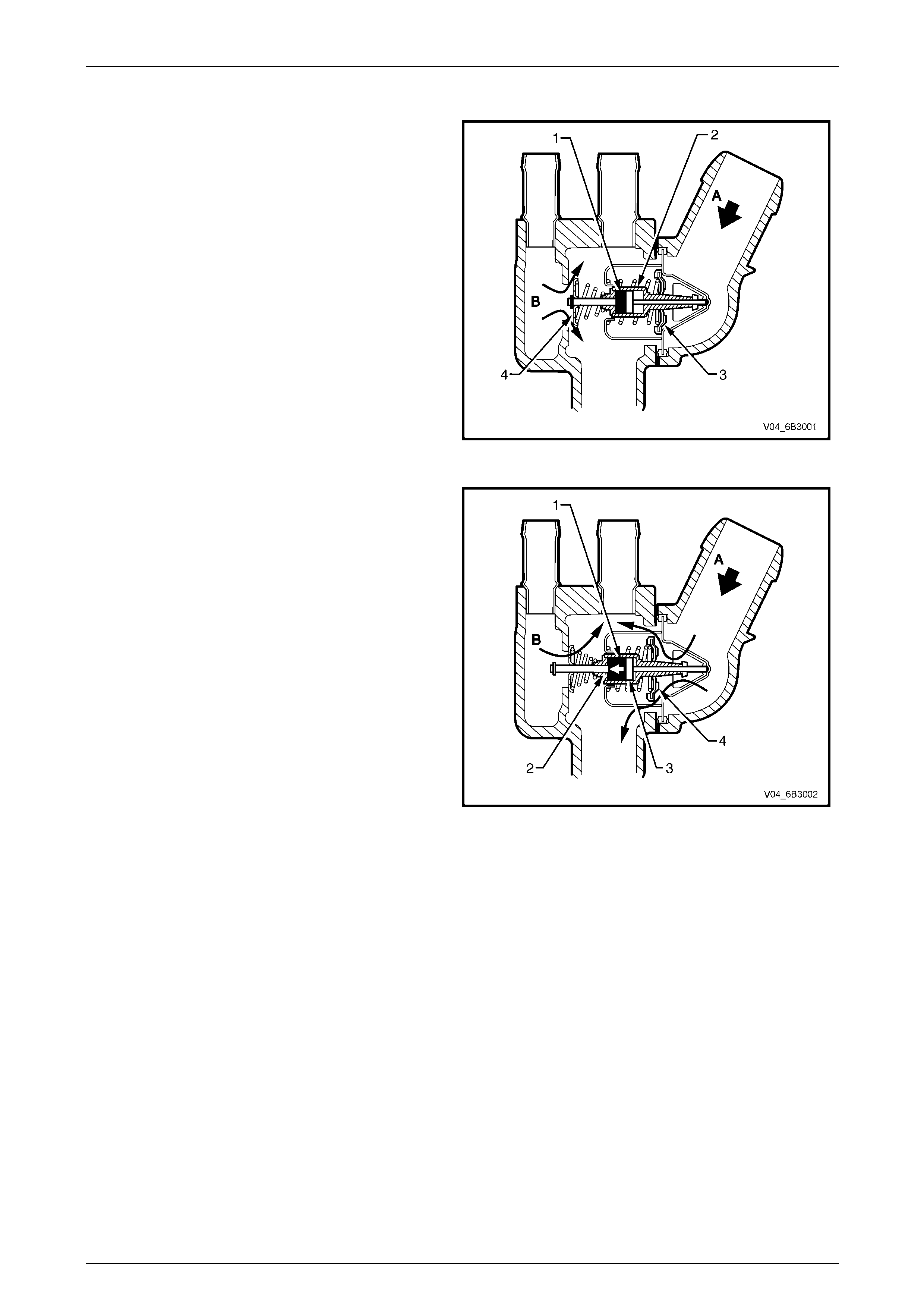
Thermostat
A wax pellet type thermostat is used to provi de rapid
engine warm-up and to regulate the coolant temperature
by controlling the coolant flow.
The wax pellet (1) located in the thermostat brass body
(2) expands when heated and contracts when cooled.
When the engine coolant is cold, the flow control valve (3)
prevents coolant flow (A) from the radiator to the engine.
However bypass coolant from the cylinder heads, which
absorb heat more quickly, is directed from the end of the
thermostat (B) and flows over the wax pell et body.
The coolant flow over the thermostat brass body heats-up
the wax pellet at the same rate as the temperature
increase in the engine.
Figure 6B4 – 7
When the coolant warms-up, the wax pellet (1) expands
pushing the thermostsat brass body base (2) against the
piston and pin (3) causing the brass body to move back
into the smaller spring cavity.
As the thermostat brass body moves back, th e flow
control valve (4) attached to the thermostat brass bod y
moves with it and allows the coolant from the radiator (A)
to flow into the engine.
At the same time, due to increased spring pressure, less
engine bypass coolant (B) flows over the thermostat
brass body.
The rate that the control valve opens is balan c ed
between the force exerted by the expand ing wax an d the
combined force exerted by the two springs.
This controlled coolant flow during cold start and initial
warming of the engine provides a controlled warming
cycle necessary to control exhaust emissions during the
critical warm-up period.
NOTE
The changes in the thermostat design do not
affect the thermostat principle of operation
and service procedure. For thermostat serv ice
procedure refer to Section 6B3 Engine
Cooling – GEN III V8 in the MY 2004 Holden
VZ Series Service Information.
Figure 6B4 – 8
Engine Cooling – HSV – Gen IV V8 Page 6B4–11
Page 6B4–11
Radiator Pressure Cap
The radiator pressure cap (1) fitted to the fille r neck (2) on
the RH radiator tank causes the cooling system to
operate at above atmospheric pressure. The higher
pressure raises the boiling point of the coolant, allowing
the engine to run at a higher temperature and resulting in
higher efficiency of both the engi ne and the cooling
system. The radiator cap contains a pr essure valve (3)
and a vacuum valve (4). The pressure valve is held
against its seat by a spring (5) which determines the
maximum operating pressure of the cooling system.
Figure 6B4 – 9
The vacuum valve (4) is held against its seat by a light
spring (not illustrated) and opens during cool-down when
the pressure drops below atmospheric as a result of
contraction of the coolant. When the differenc e between
atmospheric and cooling syst em pressure becomes
sufficient to overcome the spring load, the vacuum valve
opens; then, under atmospheric pressure, coolant from
the overflow reservoir flows back into the cooling system
in an attempt to bring the cooling system pressure up to
atmospheric. In this way the radiator hoses are prevente d
from collapsing and the coolant is maintai ne d at the ide al
level.
Figure 6B4 – 10
Coolant Overflow Reservoir
The coolant overflow reservoir is located on the left-hand
front of the engine compartment, between the radiator
support panel and the air cle aner assembly. A hose
connects the reservoir to the radiator overflow
connection.
As the engine temperature rises the coolant is heated
and expands. The coolant displaced by expansion flows
from the radiator into the reservoir. When the engine
cools down the process is reversed with coolant flowing
back into the cooling system.
The coolant level should be maintained between the
indicator arrows (A) on the reservoir’s dipstick when the
engine is cold.
Figure 6B4 – 11
Engine Cooling – HSV – Gen IV V8 Page 6B4–12
Page 6B4–12
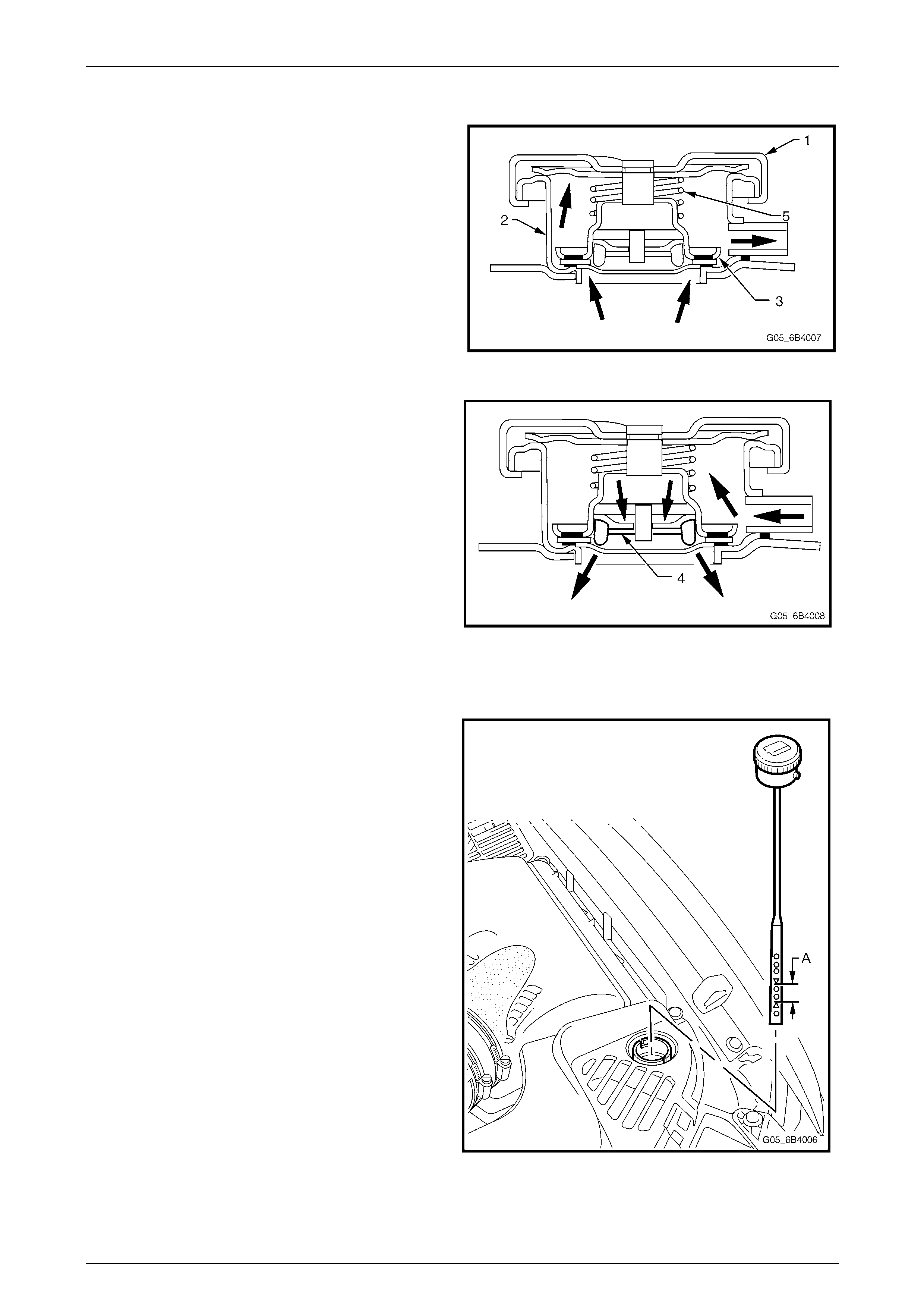
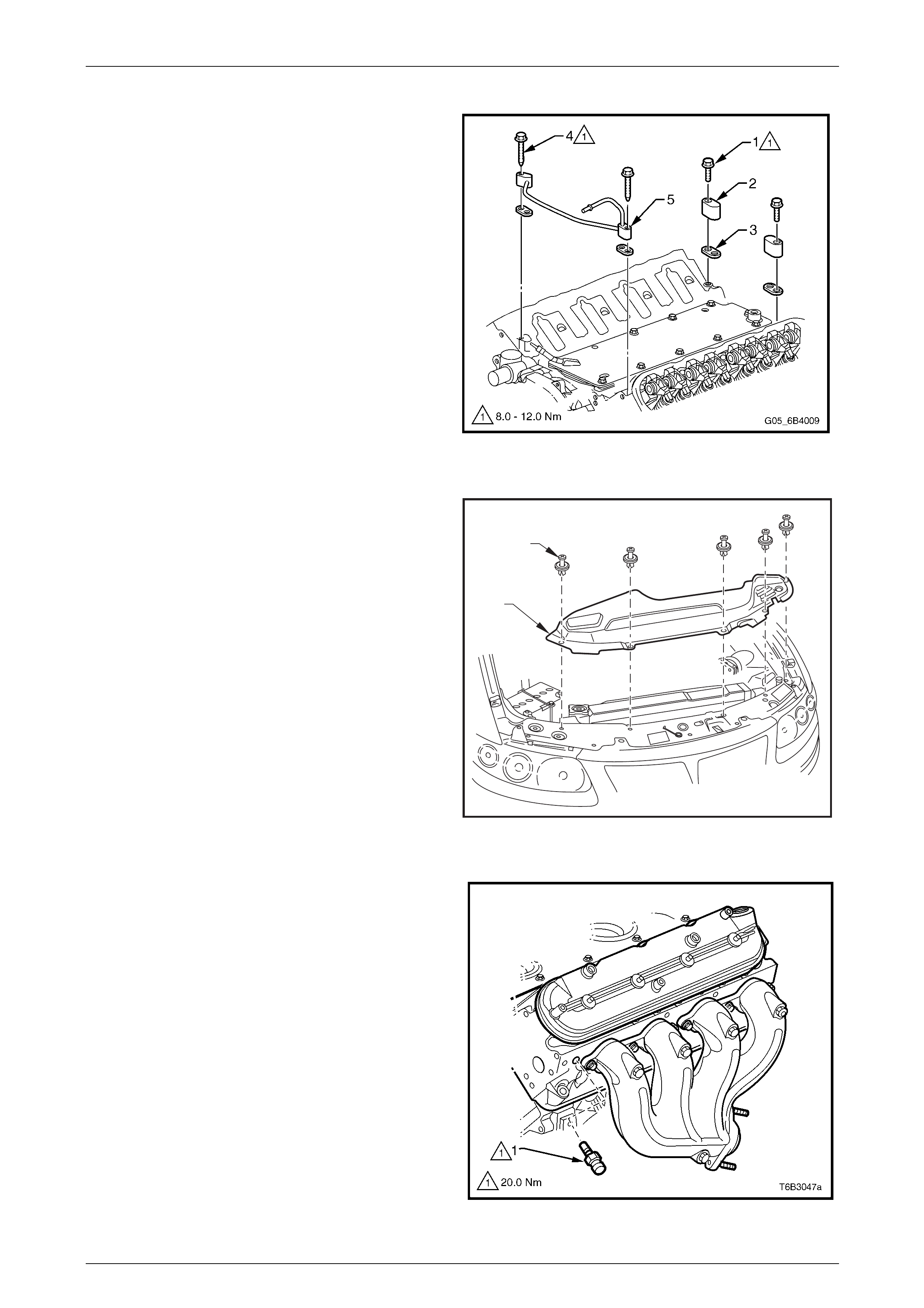
Vapour Vent System
Any vapour that develops in the engine, or air trapped
when the cooling system is being filled, is routed back to
the radiator. The vapour or air passes through a vent pipe
(1) fastened to the front of the cylinder heads at two
places by double-ende d studs (2). The rear locations are
blocked-off by two vent covers (3). All four locations ar e
sealed by gaskets (4).
A hose connects the vent pipe to the radiator cap filler
neck.
Figure 6B4 – 12
Air Baffles and Ducts
The front air duct and baffle carry over from the MY 2004
Holden VY Series vehicles, as does the o il pan under-
tray. A redesigned radiator upper shroud is fitted.
1
2
Figure 6B4 – 13
Coolant Temperature Sensor
A coolant temperature sensor (1) is mounted in the front of
the left hand cylinder head.
The coolant temperature sen sor gen erates a signal that is
used by the Engine Control Module (ECM) for calculation of
the various engine management functio ns. This information
is transmitted to other control modules, e.g. Instruments for
the temperature gauge function, on the serial data bus.
Figure 6B4 – 14
Engine Cooling – HSV – Gen IV V8 Page 6B4–13
Page 6B4–13
2 Service Operations
2.1 Service Notes
Safety
Before removing the radiator cap, all ow the engine to cool to ambient temperature (less than 50 °C), place a shop rag
over the cap and slowly turn the cap anti-clockwise to the detent position. Any residual pressure will be released into the
dam under the cap and thence to atmosphere through the overflow reservoir. When it is clear that all cooling system
pressure has been released the cap may be further turned anti-cl ockwise to the stop and then removed.
Do not remove the radiator cap when the
engine is hot, even if the cooling system
requires filling. Sudden release of cooling
system pressure is very dangerous and may
result in the coolant surging out and over the
person removing the cap leading to possible
serious injury.
The vehicle is fitted with twin electric radiator
cooling fans. When working around the
engine compartment with the engine running
or the ignition on, keep clear of the fans as
they may start without warning.
Periodic Servicing
The cooling system requires little care except for maintaining the coolant to the correct le vel in the overflow reservoir and
periodic servicing at the time or distanc e intervals as specified in the Owner’s Handbook.
Periodic servicing includ es:
1 Checking the coolant level. Refer to 2.3 Draining and Filling Cooling System in this Section.
2 Checking the coolant concentration, refer to Section 6B3 Engine Cooling -
3.2 Coolant Maintenance, Testing Coolant Concentration in the MY 2004 Holden VZ series Service Information.
3 Pressure test the cooling system and radiator cap, refer to 2.6 Pressure Testing in this Section.
4 Check / tighten hose clamps and inspect all hoses, refer to 2.4 Coolant Hoses in this Section.
Always wear protective safety glasses when
working with spring-type hose clamps. Failure
to do so may result in eye injury.
5 Clean-out the cooling system, refer to 2.5 Cleaning Co oling System in this Section, and refill,
refer to 2.3 Draining and Filling Cooling System in this Section.
Environmental Issues
To reduce the impact on the environment and the maintenance cost, whenever the coolant is to be drained from the
engine first check the service records to ascertain when the coolant was last changed. If more than six months’ life
remains before the next coola nt change is due, proceed as follows:
1 Drain the coolant from the engine into a cle an container of at least 15 L capacity ensuring that the coolant is not
contaminated in the process.
2 Refill the engine with the drained coolant after repairs have been completed.
3 Top-up as required using th e specified coolant, refer to 2.2 Coolant Maintenance, Topping-up Cooling System in
this Section.
Engine Cooling – HSV – Gen IV V8 Page 6B4–14
Page 6B4–14
2.2 Coolant Maintenance
Except for topping-up det ail, coolant maintenance carries over from Section 6B3 Engine Cooling -
3.2 Coolant Maintenance in the MY 2004 Holden VZ Series Service Information.
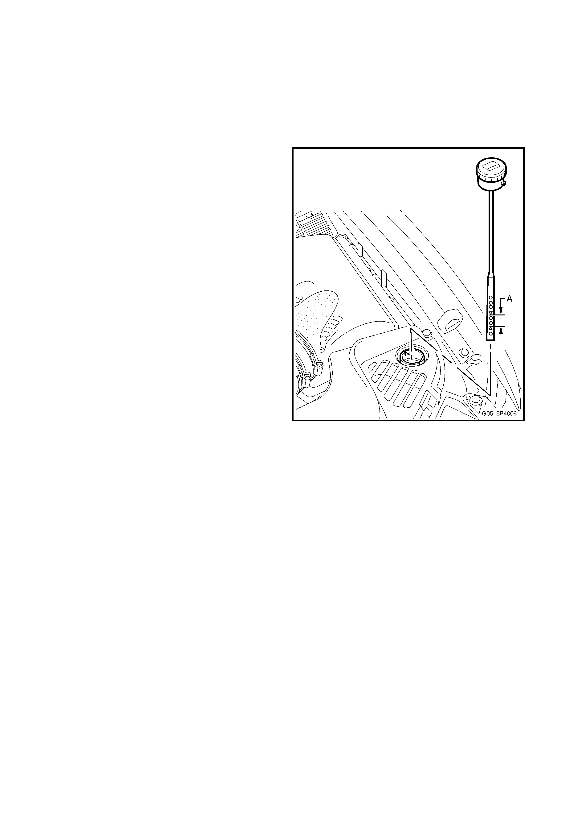
Topping-up Cooling System
The coolant level must be maintain ed within the range (A)
between the marks on the overflow reservoir dipstick with
the engine cold.
Pre-mixed coolant (50% DE X-COOL® long-life coolant or
equivalent to GM specification 6277M with 50% clean,
good quality water) may be added as necessary to obtain
the required level, refer to
2.3 Draining and Filling Cooling System in this Section.
Figure 6B4 – 15
Engine Cooling – HSV – Gen IV V8 Page 6B4–15
Page 6B4–15
2.3 Draining and Filling Cooling System
Draining
1 Remove the five retainers securing the radiator upper shroud by carefully lifting the in ner stud with a small
screwdriver and remove the shroud, refer to Figure 6B4 – 13.
2 Remove the oil pan under-tray, refer to Section 6B3, Engine Cooling – GEN III V8 in the MY 2004 Holden VZ
Series Service Information.
3 Allow the engine to cool to ambient temperature (less than 50 °C) and slowly remove the radiator cap, refer to
2.1 Service Notes, Safety in this Section.
Do not remove the radiator cap whilst the
engine coolant temperature is above 50 °C as
personal injury will most likely occur.
4 Place a suitable clean contain er of capacity at least 15 L under the left-hand radi ator side tank and drain the
coolant by opening the drain cock at the bottom of the radiator. Refer to 2.1 Service Notes, Environmental Issues in
this Section.
Filling
1 Ensure that the drain cock at the bottom of the left-hand side radiator tank is closed.
2 Ensure that all coolant hoses are correctly installed and firmly clamped.
Always wear eye protection when working
with spring-type hose clamps. Failure to do
so may result in eye injury.
3 If new coolant is required, make-up a mixture consisting of 50% DEX-COOL® long-life coolant or equivalent to GM
specification 6277M and 50% clean, good quality water. The quantity required will depend on whether the cooling
system was completely drained, in which case approximately 14.5 L will be required.
Do not mix different types of anti-freeze
or corrosion inhibitors as they may
be incompatible. Always check which
coolant is to be added to the vehicle
being serviced. If a different type has
been used, or has been accidentally added,
flush the system with clean water, refer to
2.5 Cleaning Cooling System in this Section.
4 Install Tool No. AU425 to the radiator filler neck in place of the radiator cap.
5 Remove the vapour vent hose from its connection at the engin e vent pipe and temporarily secure the end of the
hose to a convenient point (e.g. the top of Tool No. AU425) above the level of the engine vent pip e con nection.
6 Fill the cooling system using the coolant mixture via Tool No. AU425 until coolant flows from the engine vent pipe
connection and all air has been e xpelled.
7 Refit the vapour vent hose to its connection at the engine vent pipe and secure with the hose clamp.
8 Remove Tool No. AU425 from the radiator and pressure test the cooling system, refer to 2.6 Pressure Testing in
this Section.
9 Check the level of coolant in the overflow reservoir and top-up as necessary,
refer to 2.2 Coolant Maintenance, T opping-up Cooling System in this Section .
10 Refit the radiator cap.
11 Set the heater control to maximum, start and run the engine until normal operating temperature is reached to
disperse the added coolant through the co oling system.
Engine Cooling – HSV – Gen IV V8 Page 6B4–16
Page 6B4–16
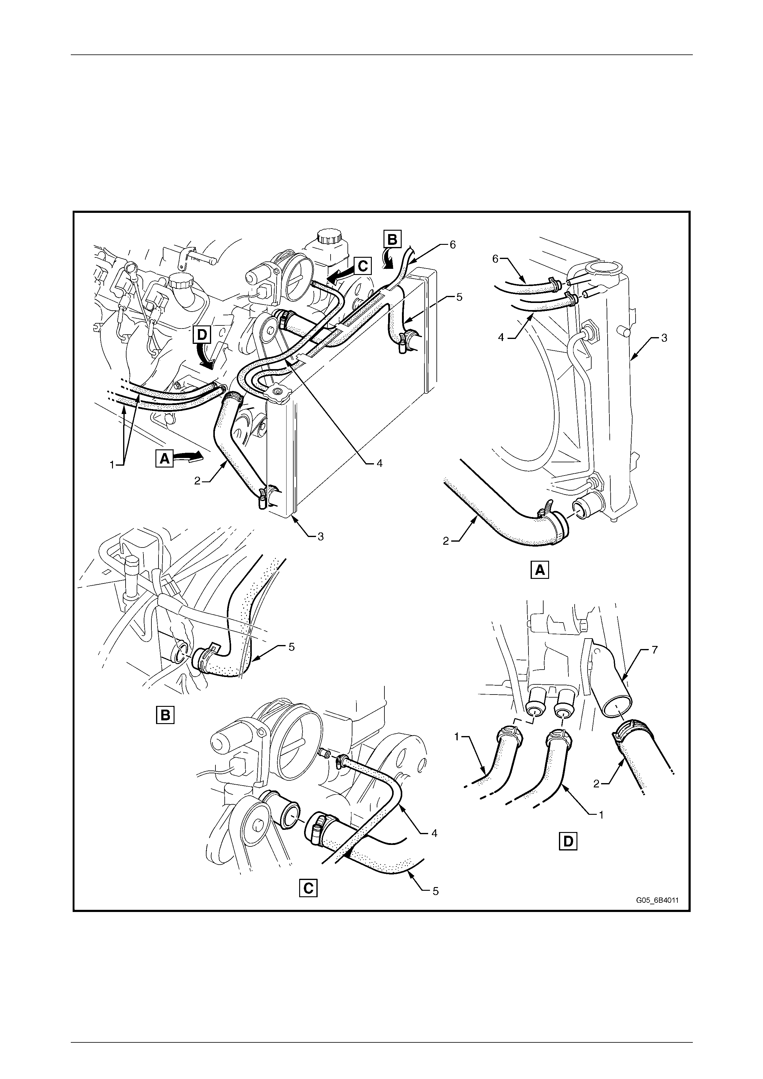
2.4 Coolant Hoses
The coolant hose layout is shown in the following illustrations.
NOTE
The engine cooling fans, fan motors and
shroud are not shown in Figure 6B4 – 16 and
Figure 6B4 – 17 in order to show the hose
routing more clearly.
Figure 6B4 – 16
Legend
1 Hoses – Heater
2 Hose – To Coolant Surge Tank
1 of 2
3 Hose – Radiator Lower 1 of 2
4 Radiator
5 Hose – Radiator Upper
6 Bridging Pipe – Radiator Hoses
7 Hose – Radiator Lower 2 of 2
8 Hose – To Coolant Surge Tank
2 of 2
9 Hose – Vapour to Radiator
10 Hose – Vapour to Surge tank
11 Pump Coolant
12 Housing – Thermostat
Engine Cooling – HSV – Gen IV V8 Page 6B4–17
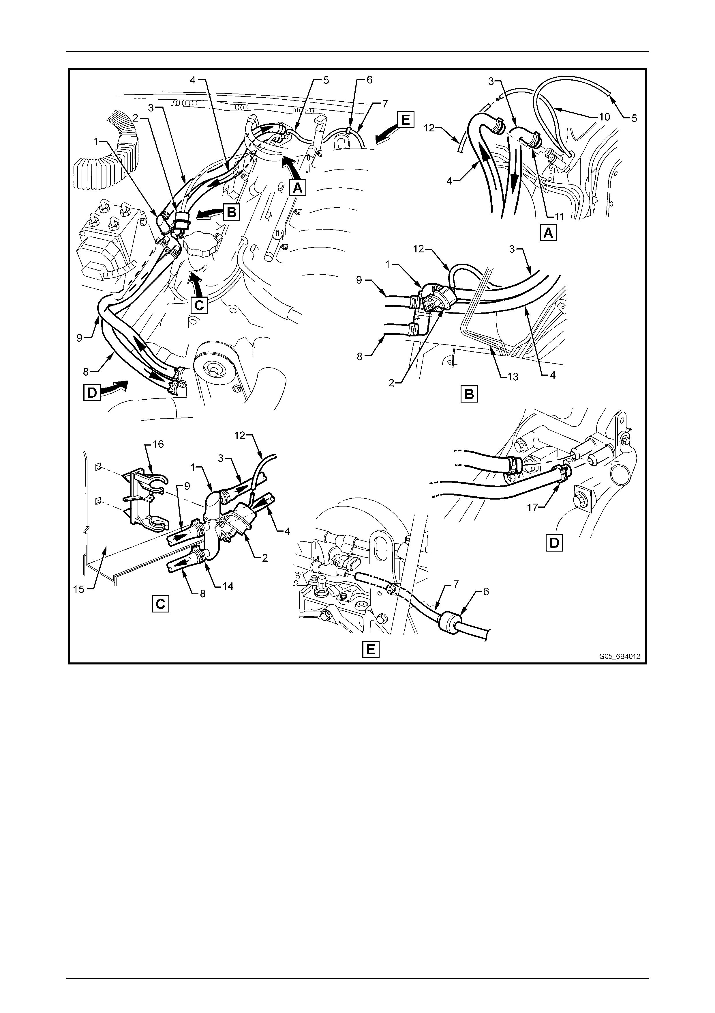
Page 6B4–17
Figure 6B4 – 17
Legend
1 Coolant Valve
2 Coolant Valve Actuator
3 Heater Hose to Interior Heater Core
4 Heater Hose from Interior Heater Core
5 Vacuum Hose – HVAC Supply
6 One-Way Check Valve
7 Vacuum Hose to Intake Manifold
8 Heater Hose to Engine
9 Hose to Coolant Surge Tank
10 Heater Hose T-piece
11 Heater Hose to T-piece
12 Heater Hose from Engine
13 Vacuum Hose to Interior Control Valve
14 Heater Hose Clamps (2 places)
15 Vacuum Hose to Coolant Valve Actuator
16 Brake Booster
17 Steering Shaft
18 Brake Lines
19 Coolant Valve Hose Clamps (4 places)
20 Right Side Wheelhouse
21 Clip - Coolant Flow Control Valve
22 Heater Hose Clamps to Engine (2 places)
23 T-piece Hose Clamps (2 places)
24 T-piece Hose Worm Drive Clamp (1 place)
NOTE
Ensure that hose connections are thoroughly
cleaned before installing a ny new hose.
Engine Cooling – HSV – Gen IV V8 Page 6B4–18
Page 6B4–18
2.5 Cleaning Cooling System
NOTE
Before carrying out reverse flushing procedures,
it is recommended that a cleaning solution be
used to loosen scale and corrosion. Use an
approved radiator cleaner following the
instructions on the container labe l.
Cooling System Reverse Flush
NOTE
When using specialised cooling system flushing
equipment, connect the equipment as
recommended by the manufacturer.
Drain the cooling system. Refer to 2.3 Draini ng and Filling Cooling System, Draining in this Section.
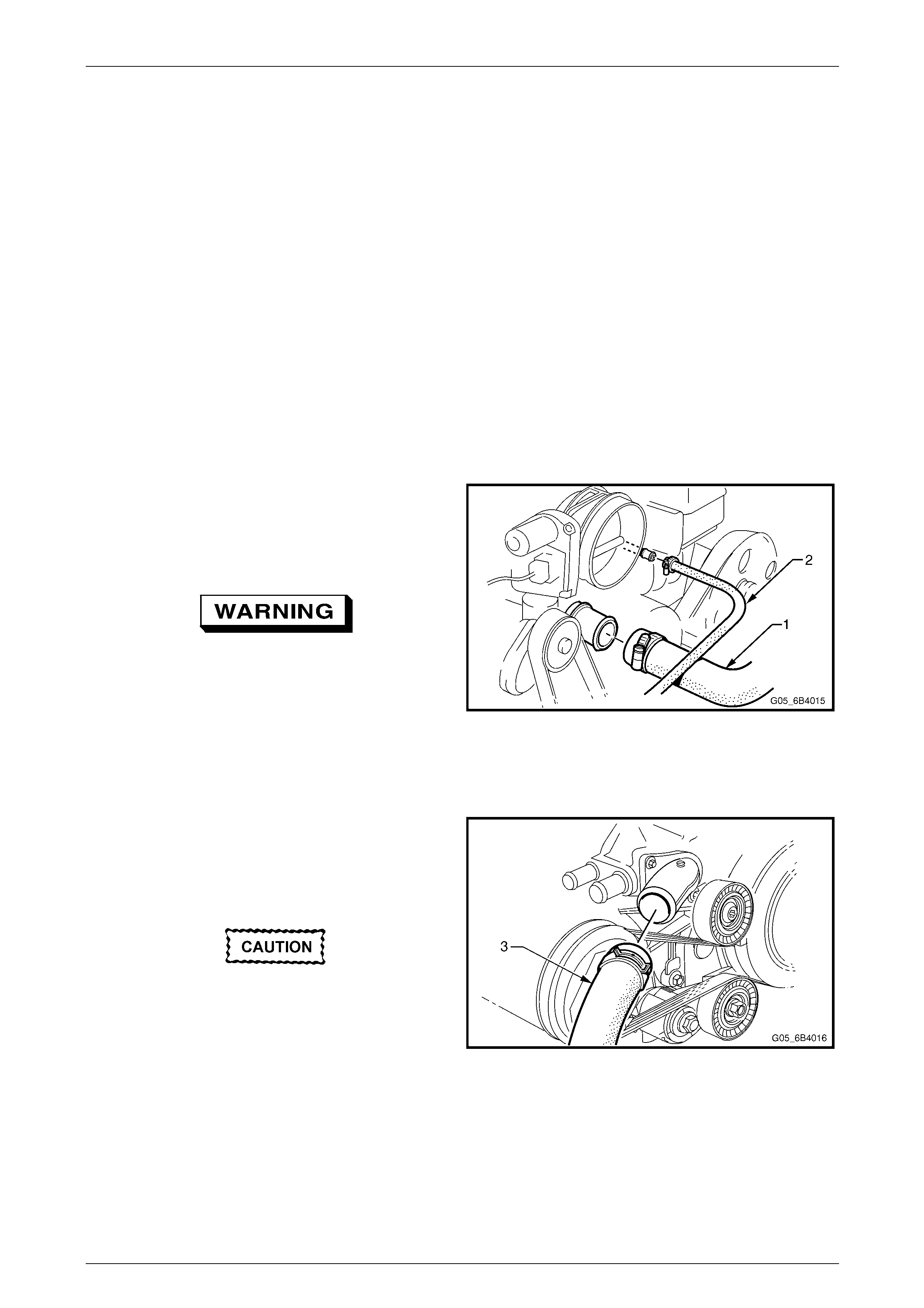
Radiator
1 Reinstall the hose to the lower right-ha nd side radiator
tank and secure with its hose clamp.
2 Remove the radiator hoses (1) and (3) from the
coolant pump connections.
Always wear eye protection when working
with spring-type hose clamps. Failure to do
so may result in eye injury.
3 Remove the vapour vent hose from its connection at
the engine vent pipe an d temporarily plug the end of
the hose.
4 Attach a lead-away hose to the left-hand side radi ator
tank hose.
Figure 6B4 – 18
5 Attach a piece fo hose between the flushing gun and
the right-hand side radiator tank hose.
6 Connect and operate the flus hing equipment as
recommended by the manufacturer.
Apply air pressure gradually and not in
excess of 110 kPa, otherwise radiator
damage will result.
7 Continue flushing until the water from the lead-away
hose runs clear.
8 Reinstall all disconn ected hoses, ensuring that they
are correctly positioned and securely clamped.
9 Fill the cooling system, refer to
2.3 Draining and Filling Cooling System, Filling in this
Section.
10 Pressure test the cooling system, refer to
2.6 Pressure Testing in this Section.
Figure 6B4 – 19
Engine Cooling – HSV – Gen IV V8 Page 6B4–19
Page 6B4–19
Engine
1 Remove the radiator hoses (1) and (2) from the coolant pump connections. Refer to Figure 6B4 – 17.
Always wear eye protection when working
with spring-type hose clamps. Failure to do
so may result in eye injury.
2 Remove the thermostat housing and thermostat from the coolant pump.
3 Remove the thermostsat from the thermostat housing and reinstall the housing to the coolant pump.
2 Remove the vapour vent hose from its connection at the radiator right-hand side tank and temporarily plu g the end
of the hose.
3 Remove both heater hoses from their connections at the coolant pump and seal the pump connections using a
scrap piece of hose and t wo hose clamps.
4 Fit a lead-away hose to the thermostat housing and a length of hose between the coolant pump outlet fitting and
the flushing equipment.
5 Connect and operate the flus hing equipment as recommended by the manufacturer.
6 Continue flushing until the water from the lead-away hose runs clear.
7 Reinstall all disconn ected hoses, ensuring that they are correctly positione d and securely clamped.
8 Fill the cooling system. Refer to 2.3 Draining and Filling Cooling System, Filling in this Section.
9 Pressure-test the cooling system. Refer to 2.6 Pressure Testing in this Section.
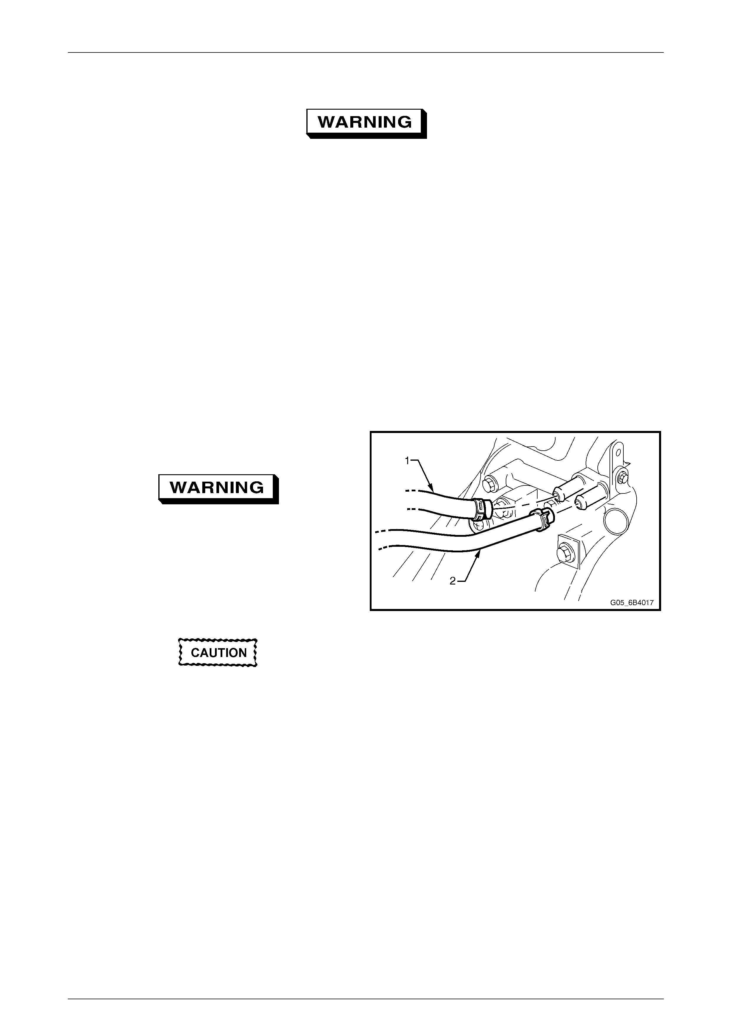
Heater Hoses and Core
1 Remove both heater hoses (1) and (2) from their
connections at the coolant pump, noting which hose
was connected to which connection.
Always wear eye protection when working
with spring-type hose clamps. Failure to
do so may result in eye injury.
2 Direct the hose that was connected to the coolant
pump’s rear-most connection into a suita bl e container
and the hose from the front connection to the flushing
gun.
3 Connect and operate the flus hing equipment as
recommended by the manufacturer.
Apply air pressure gradually and not in
excess of 110 kPa, otherwise heater core
damage will result.
4 Reinstall all disconn ected hoses, ensuring that they
are correctly positioned and securely clamped.
5 Fill the cooling system, refer to
2.3 Draining and Filling Cooling System, Filling in this
Section.
6 Pressure test the cooling system, refer to
2.6 Pressure Testing in this Section.
Figure 6B4 – 20
Engine Cooling – HSV – Gen IV V8 Page 6B4–20
Page 6B4–20
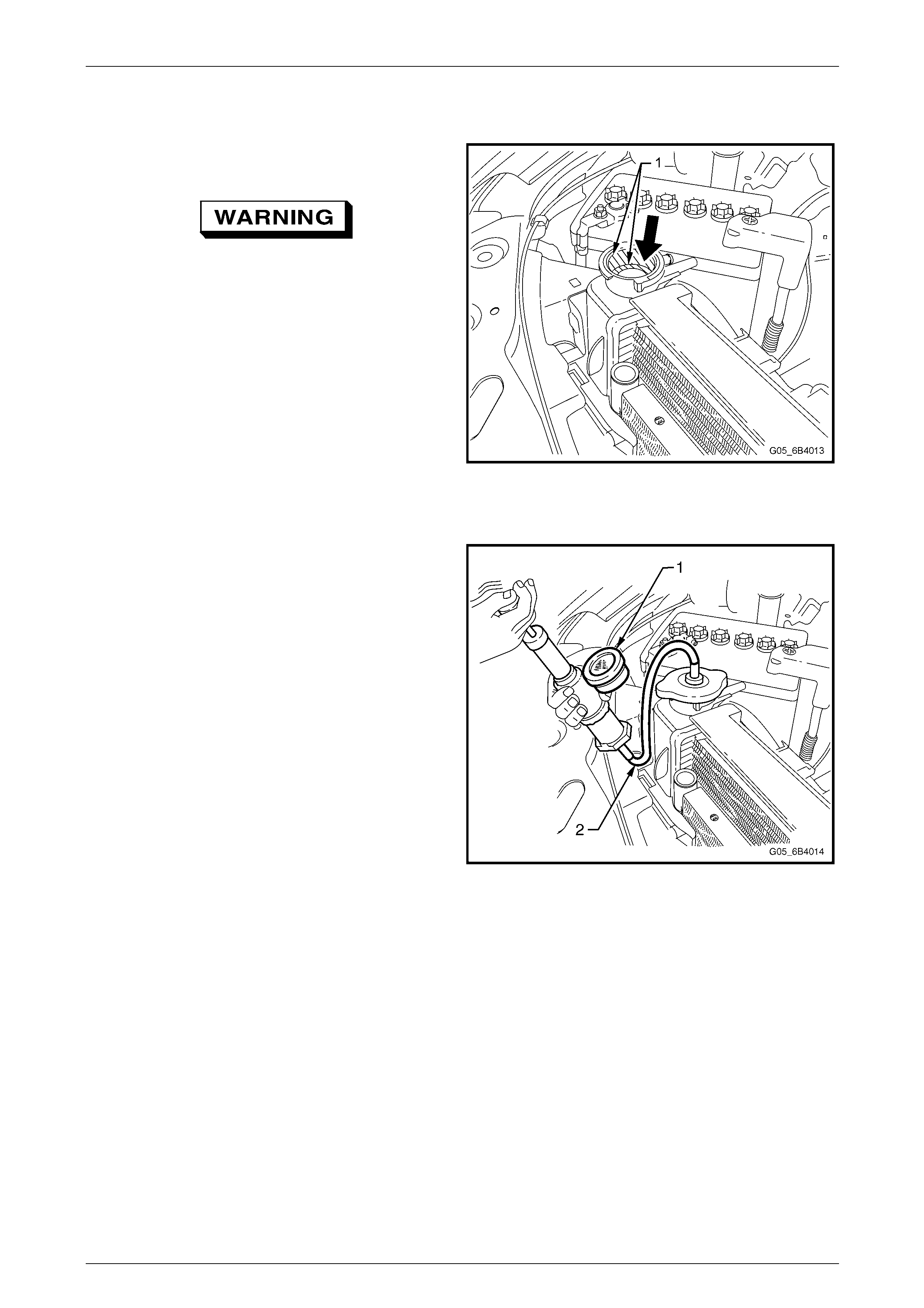
2.6 Pressure Testing
1 Allow engine to cool to ambient temperature (less than
50ºC), then carefully remove the radiator cap.
Do not remove radiator cap while the
engine coolant temperature is above 50ºC,
as personal injury will most likely occur.
2 Ensure that coolant level is correct.
3 Connect a commerciall y available cooling system
pressure tester (1) ref Fig. 6B4-22, to the radiator
filler neck by using the hose supplied (2) ref Fig.
6B4-22 or other arrangement and us ing
compressed air, blow dry any spilled coolant around
the radiator neck (1) ref Fig 6B4-21. Pressurise
cooling system to not more than 110 kPa and check
for leaks at the following points:
Figure 6B4 – 21
a. All hoses and hose connectio ns
b. Radiator seams and core.
c. Corroded or faulty engine core plugs.
d. Coolant pump and gaskets and O-ring sea ls.
e. Vehicle heater system
f. Check engine oil dipstick for evid ence of
engine oil contamination with coolant.
4 If pressure will not hold there is a leak in
the cooling system. Rep air as required.
NOTE
If visable loss of coolant is not evident from pressure testing,
then the use of a dye and black light ma y be necessary.
Figure 6B4 – 22

Engine Cooling – HSV – Gen IV V8 Page 6B4–21
Page 6B4–21
3 Engine Cooling System
Diagnostics
3.1 Engine Overheating
Definition
Engine temperature lamp co mes ON and stays ON, or the temperature gauge shows hot, or coolant overflows from the
surge tank onto the ground while the engine is running.
Step Action Value(s) Yes No
1 1 Check for a loss of coolant.
2 Refer to 2.2 Coolant Maintenance, T opping Up
Cooling System.
Is there a loss of coolant ?
- Refer to 3.2 Loss
Of Coolant Go to Step 2
2 1 Check for correct operation o f cooling fans. Refer
Section 6C3 Powertrain Management.
2 Replace cooling fan/s and/or motor as necessary.
Refer 2.15 Cooling Fans And Shroud Assembly.
Does the engine still overheat?
- Go to Step 3 System OK
3 1 Check for incorrect or damaged cooling fan
blade(s).
2 Check for the correct fan blade(s) part number.
3 Replace fan/s as necessary. Refer 2.15 Coo ling
Fans And Shroud Assembly.
Does the engine still overheat?
- Go to Step 4 System OK
4 1 Check for weak engine coolant solution.
2 Refer to 2.2 Coolant Maintenance, T esting
Coolant Concentration.
Does the engine still overheat?
- Go to Step 5 System OK
5 1 Check for obstructed radiator air flow or bent
radiator fins.
2 If necessary, remove or relocate added-on p arts
that block air to the radiator. Clean away any
insects, leaves, or other debris.
Does the engine still overheat?
- Go to Step 6 System OK
6 1 Check for a loss of system pressure.
2 Conduct a test on the pressure cap. Refer to
2.8 Pressure Testing, Screw-On Pressure Cap
Testing.
Does the engine still overheat?
- Go to Step 7 System OK
7 1 Check for a faulty Engine Coolant Temperature
(ECT) sensor. Refer to Section 6C3 Powertrain
Management
2 Replace sensor as necessary.
Does the engine still overheat?
- Go to Step 8 System OK

Engine Cooling – HSV – Gen IV V8 Page 6B4–22
Page 6B4–22
Step Action Value(s) Yes No
8 1 Check for a damaged coolant overflow reservoir.
2 Check for a leaking or kinked reservo ir tank h ose.
NOTE
If necessary, replace the surge tank hose
and / or replace the coolant surge tank.
Refer to 2.10 Coolant Recovery Sur ge Tank.
Does the engine still overheat?
- Go to Step 9 System OK
9 1 Check the tension of the e ngine accessory drive
belt. Refer to 2.6 Engine Accessory Drive Belt
Tension.
2 Replace the engine accessory drive belt as
necessary. Refer to 2.7 Engine Accessory Drive
Belt.
Does the engine still overheat?
- Go to Step 10 System OK
10 1 Check for blocked cooling system passages.
2 Reverse flush the cooling system. Refer to
2.5 Cleaning Cooling System.
Does the engine still overheat?
- Go to Step 11 System OK
11 1 Check for correct thermostat operation. Refer
2.9 Thermostat. Test.
2 Replace the thermostat assembly as necessary.
Refer 2.9 Thermostat.
Does the engine still overheat?
- Go to Step 12 System OK
12 1 Check for correct coolant pump operation.
2 Replace coolant pump assembly as necessary.
Refer 2.14 Coolant Pump.
Does the engine still overheat?
- Go to Step 13 System OK
13 1 Check the radiator cool ing capacity.
Is the radiator the correct part?
- Go to Step 15 Go to Step 14
14 1 Replace the radiator with the correct part.
Is the repair complete?
- System OK -
15 Does the engine still overheat? - Refer to Section
7C3 Automatic
Transmission /
Section 6A3
Engine Mechanical
Diagnosis
System OK

Engine Cooling – HSV – Gen IV V8 Page 6B4–23
Page 6B4–23
3.2 Loss of Coolant
Definition
The coolant level in the surge tank continually requires topp ing up or there is evidence of a sudden coolant loss from the
surge tank.
Step Action Value(s) Yes No
1 1. Check for an incorrect or faulty screw-on pressure
cap.Conduct a test on the pressure cap. Refef 2.8
PRESSURE TESTING. Screw-On Pressure Testing in
this section.
2. Replace the screw-on pressure cap as n ecessary.
Is a coolant loss still evident?
- Go to Step 2 System OK
2 1. Check for leaking or damaged coolant surge tank.
2. Replace thecoolant surge tank Refer
2.10 Coolant Surge Tank. In this section.
Is a coolant loss still evident?
- Go to Step 3 System OK
3 1. Conduct a pressure test of the cooling s ystem. Refer
2.8 Pressure Testing. Cooling System Pressure
Testing in this section.
Does test indicate a pressure loss in the co oling
system?
- Go to Step 4 System OK
4 Is there evidence of an external coolant leak? - Go to Step 5 Go to Step 12
5 1. Check for loose or damaged surge tank,radi ator and
heater hoses. Refer 2.4 Coolant Hoses. In this
section.
2. Replace hoses as necessary.
Is a coolant loss still evident?
- Go to Step 6 System OK
6 1. Check for coolant leak from the coolant pump
gaskets.
2. Replace gaskets as necessary Refer 2.13 Coolant
Pump. In this section.
Is a coolant loss still evident?
- Go to Step 7 System OK
7 1. Check for coolant leak from the coolant pump rear
O-ring seal and thermostat housing O-ring s eal.
2. Replace O-ring seals as necessary. Refef 2.9
THERMOSTAT and 2.13 COOLANT PUMP. In this
section.
Is a coolant loss still evident?
- Go to Step 8 System OK
8 1. Check for coolant leak from the coolant pump shaft
seal
2. Replace coolant pump as necessary.
Refer 2.13 Coolant Pump. In this section
Is a coolant loss still evident?
- Go to Step 9 System OK
9 1. Inspect the radiator for coolant leaks.
Are coolant leaks from the radiator evident ?
- Go to Step 10 System OK

Engine Cooling – HSV – Gen IV V8 Page 6B4–24
Page 6B4–24
Step Action Value(s) Yes No
10 1. If radiator leaks are minor repair as detailed in 2.16
RADIATOR. Radiator repair procedure in this
section.
2. If radiator coolant leaks are major replace the
radiator. Refer 2.15 Radiator in this section
Is a coolant loss still evident?
- Go to Step 11 System OK
11 1. Check for coolant leaks from the heater core.
2. Replace heater core as necessary Refer 2B Air
Conditioning – Removal & Installation.
Is a coolant loss still evident?
- Go to Step 12 System OK
12 1. Check for coolant leaks from the following:
● Engine block plugs
● Vapour pipe and / or fittings
● Cylinder head gaskets.
2. Make the nec essary repairs or replace affected
components. Refer Section 6A3 Engi ne Mechanical
Is / are the repairs complete?
- System OK -

Engine Cooling – HSV – Gen IV V8 Page 6B4–25
Page 6B4–25
3.3 Engine Fails to Reach Normal Operating
Temperature
Step Action Value(s) Yes No
1 1. Check for correct coolant level in the coolant surge
tank. When checked cold the level s hould be at the
FULL COLD mark.
Is the coolant level correct?
_ Go to Step 3 Go to Step 2
2 1. Top up with correct mixture of extended life anti-
freeze coolant (conforming to GM8277M) and clean
good quality water. Refer 2.2 Coolant Maintenance
in this section.
Does the engine reach normal operati ng temperature
now?
_ System OK Go to Step 3
3 1. Check for a blockage in the cooling system
passages.
2. Revers e flush the cooling system Refer
2.5 Cleaning Cooling System in this section.
Does the engine reach normal operati ng temperature
now?
_ System OK Go to Step 4
4 1. Check that the correct thermostat is fitted.
2. Check that the thermostat is not stuck in the
open position.
3. Replace the thermostat as necessary Refer
2.9 Thermostat in this section.
Are repairs complete?
_ System OK _

Engine Cooling – HSV – Gen IV V8 Page 6B4–26
Page 6B4–26
4 Specifications
General
Radiator Cap Pressure Rating Nominal.......................................................................103 kPa
Range...............................................................................................................96.5 – 124 kPa
Cooling System Capacity.........................................................................................14.3 Litres
Coolant Corrosion Inhibitor..............................................................................7 litres (approx)
NOTE
DEX-COOL® long life coolant or equivalent, to
GM Specification 6277M, required when
changing coolant.
Thermostat
Type...............................................................................................Power element (wax pellet)
Starts to open at ..............................................................................................................86° C
Fully open at..................................................................................................................100° C
Coolant Pump
Type.........................................................................................................................Centrifugal
Drive.........................................................................................Multi-ribbed, Serpentine V-belt
Bearing Type ......................................................................................Double-row ball bearing
Radiator
Core type......................................................................................... Aluminium crossflow core
Overall Width...............................................................................................................826 mm
Overall Height..............................................................................................................495 mm
Core Width...................................................................................................................674 mm
Core Height .................................................................................................................427 mm
Core Thickness..............................................................................................................35 mm
Plastic tanks ................................................................................Nylon 6,6 (30% Glass Filled)
Radiator Hoses
Lower – Number and type ................................................................................. Two, Moulded
Upper – Number and type ................................................................................. One, Moulded

Engine Cooling – HSV – Gen IV V8 Page 6B4–27
Page 6B4–27
Small Engine Cooling Fan (Left)
Fan – Design ..........................................Asymmetrical spaced, curved blades with outer ring
Material..................................Nylon 6,6 (30% Glass Filled), with zinc coated metal hub insert
Number of Blades...................................................................................................................5
Diameter......................................................................................................................293 mm
Fan Motor – Type .........................................Dual speed, 4 brush with 4 permanent magnets
Housing ........................................................... Semi-sealed, zinc coated steel with drain hole
Direction of Rotation.......................................Counter-clockwise (as viewed from motor side)
Power .......................................................................................................180 Watts (nominal)
Rotational Speed (with 12 volts applied, Radiator
and Condenser Installed):
Stage 1...........................................................................................................2,050 ± 150 rpm
Stage 2...........................................................................................................2,300 ± 150 rpm
Large Engine Cooling Fan – (Right)
Fan – Design ..........................................Asymmetrical spaced, curved blades with outer ring
Material..................................Nylon 6,6 (30% Glass Filled), with zinc coated metal hub insert
Number of Blades...................................................................................................................5
Diameter......................................................................................................................342 mm
Fan Motor – Type .........................................Dual speed, 4 brush with 4 permanent magnets
Housing ........................................................... Semi-sealed, zinc coated steel with drain hole
Direction of Rotation.......................................Counter-clockwise (as viewed from motor side)
Power .......................................................................................................220 Watts (nominal)
Rotational Speed (with 12 volts applied, Radiator
and Condenser Installed:
Stage 1...........................................................................................................2,350 ± 150 rpm
Stage 2...........................................................................................................2,750 ± 150 rpm

Engine Cooling – HSV – Gen IV V8 Page 6B4–28
Page 6B4–28
5 Torque Wrench Specifications
Coolant Pump to Cylinder Block Bolts:........................................................N.m
Stage 1...........................................................................................................15
Stage 2...........................................................................................................25
Coolant Pump Rear Cover Bolts ....................................................................14
Engine Accessory Drive Belt Tensioner Bolt..................................................50
Fan Motor to Shroud Screw...........................................................................5.0
Oil Cooler to Side Tank Nuts..........................................................................25
Oil Pan Under-Tray Bolts................................................................................30
Quick Connect Fitting to Transmission Fluid Cooler.......................................25
Surge Tank Bracket Nuts .........................................................................6 – 11
Thermostat Housing to Coolant Pump Bolts...................................................14
Engine Cooling – HSV – Gen IV V8 Page 6B4–29
Page 6B4–29
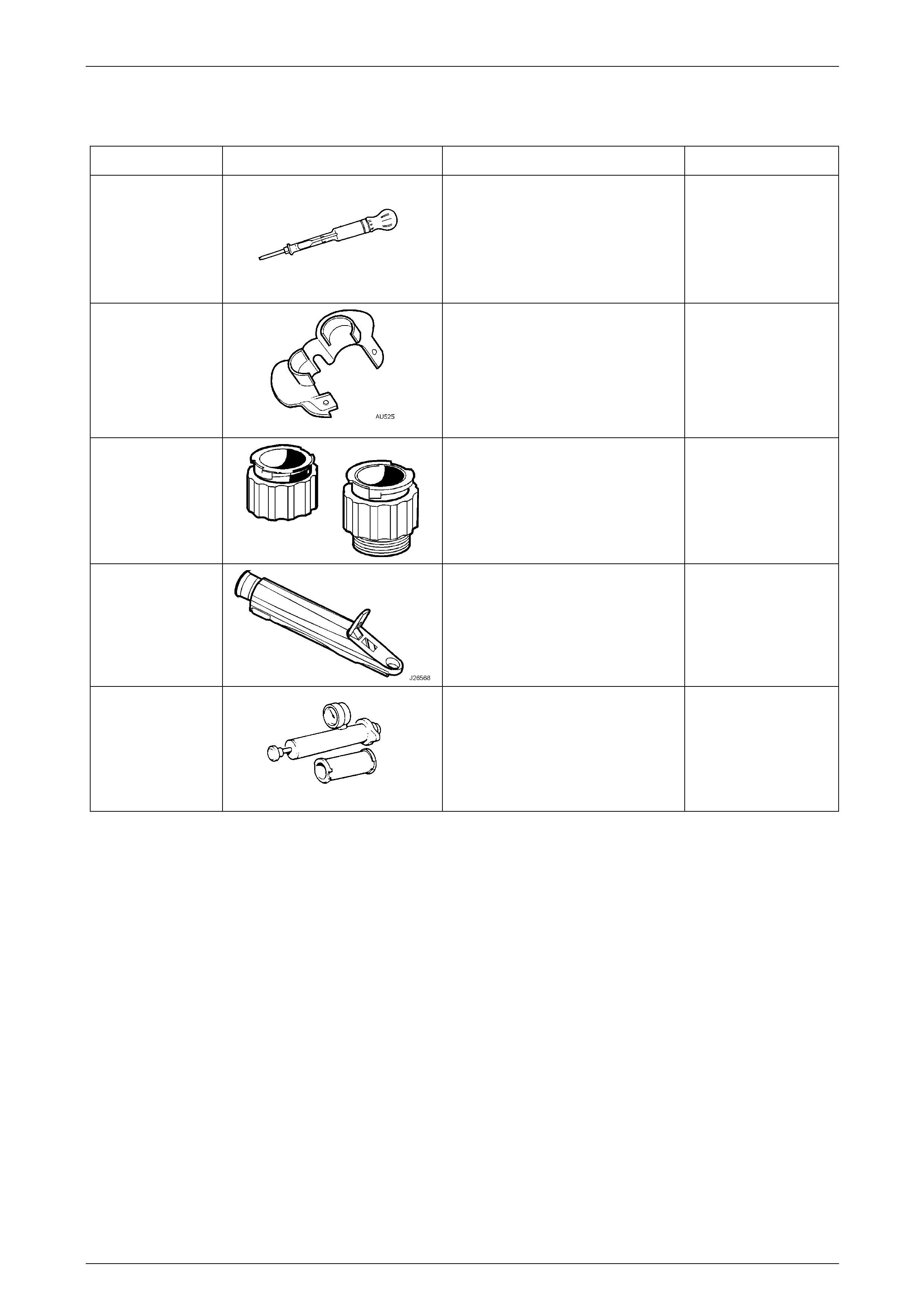
6 Special Tools
Tool Number Illustration Description Tool Classification
AU505
Cooling System Hydrometer
Also released as AU435
Also commercially available
Mandatory
AU525
Quick Connect Release Tool
Use to release the quick connect
fittings on the automatic transmission
fluid cooler lines at the radiator end,
when the vehicle is so equipp ed.
Previously released
Mandatory
J 24460-92
Cooling System Test Adaptors
Used to pressure test the screw-on
cooling system pressure cap and the
cooling system.
Previously released
Mandatory
J 26568
Refractometer
Previously released, also under the
number, AU435
Mandatory
N/A
Cooling System Pressure Tester
Used in conjunction with adaptors J
24460-92
Commercially available
Available