
Engine Management – HSV - Gen IV V8 Page 6C4–1
Page 6C4–1
Section 6C4
Engine Management – HSV - Gen IV V8
1 Component Replacement......................................................................................................................3
1.1 Accelerator Pedal Position (APP) Sensor............................................................................................................ 3
Remove................................................................................................................................................................... 3
Reinstall.................................................................................................................................................................. 4
1.2 Accelerator Pedal Position (APP) Sensor Support Bracket............................................................................... 5
1.3 Air Cleaner Assembly............................................................................................................................................ 6
Air Cleaner Upper Housing................................................................................................................................... 6
Remove.............................................................................................................................................................. 6
Reinstall ............................................................................................................................................................. 6
Air Cleaner Lower Housing................................................................................................................................... 7
Remove.............................................................................................................................................................. 7
Reinstall ............................................................................................................................................................. 7
1.4 Engine Control Module (ECM) .............................................................................................................................. 8
Remove................................................................................................................................................................... 8
Reinstall.................................................................................................................................................................. 9
1.5 Engine Control Module (ECM) Bracket Assembly ............................................................................................ 10
Remove................................................................................................................................................................. 10
Reinstall................................................................................................................................................................ 10
1.6 EVAP Canister Purge Solenoid Valve ................................................................................................................ 11
Remove................................................................................................................................................................. 11
Reinstall................................................................................................................................................................ 11
1.7 Heated Oxygen Sensors (HO2S)......................................................................................................................... 12
Service Precautions............................................................................................................................................. 12
Remove................................................................................................................................................................. 12
Reinstall................................................................................................................................................................ 13
Test ....................................................................................................................................................................... 13
Front Sensors................................................................................................................................................... 13
Rear Sensors ................................................................................................................................................... 14
1.8 Intake Air Temperature (IAT) Sensor.................................................................................................................. 15
Test ....................................................................................................................................................................... 15
Resistance Check ............................................................................................................................................ 15
1.9 Mass Air Flow (MAF) Sensor and Intake Air Duct............................................................................................. 16
Remove................................................................................................................................................................. 16
Reinstall................................................................................................................................................................ 17
1.10 Throttle Body........................................................................................................................................................ 18
Handling Precautions.......................................................................................................................................... 18
Remove................................................................................................................................................................. 18
Inspect .................................................................................................................................................................. 19
Reinstall................................................................................................................................................................ 20
1.11 Camshaft Position (CMP) Sensor Replacement................................................................................................ 21
Removal Procedure............................................................................................................................................. 21
Installation Procedure ......................................................................................................................................... 22
Techline

Engine Management – HSV - Gen IV V8 Page 6C4–2
Page 6C4–2
2 Fastener Tightening Specifications ...................................................................................................23
3 MY2004 HSV VZ LS2 Diagnostic Trouble Codes...............................................................................24
4 Diagnostics...........................................................................................................................................30
4.1 DTC P0513, P0633, P1629, P1632, P1648, P1677, P1678, and P1679 – Immobiliser Signal........................... 30
DTC Description................................................................................................................................................... 30
Circuit Description............................................................................................................................................... 30
Condition for Running the DTCs........................................................................................................................ 31
Condition for Setting the DTCs........................................................................................................................... 31
Conditions for Clearing the DTCs ...................................................................................................................... 31
Additional Information......................................................................................................................................... 31
Test Description................................................................................................................................................... 31
Diagnostic Table for DTC P0513, P0633, P1629, P1632, P1648, P1677, P1678, and P1679 ........................... 32
4.2 DTC P1575 – Extended Travel Brake Switch Failure ........................................................................................ 33
Circuit Description............................................................................................................................................... 33
DTC Descriptor..................................................................................................................................................... 33
Conditions for running the DTC ......................................................................................................................... 33
Conditions for setting the DTC........................................................................................................................... 33
Action taken when the DTC sets ........................................................................................................................ 33
Conditions for clearing the MIL/DTC.................................................................................................................. 33
Diagnostic Aids.................................................................................................................................................... 33
Test Description................................................................................................................................................... 33
Diagnostic Table for DTC P1575......................................................................................................................... 34
4.3 DTC P0719 – Brake Switch Failure..................................................................................................................... 35
Circuit Description............................................................................................................................................... 35
DTC Descriptor..................................................................................................................................................... 35
Conditions for Running the DTC........................................................................................................................ 35
Conditions for Setting the DTC........................................................................................................................... 35
Action Taken When the DTC Sets ...................................................................................................................... 35
Conditions for Clearing the DTC ........................................................................................................................ 35
Diagnostic Aids.................................................................................................................................................... 35
Test Description................................................................................................................................................... 35
Diagnostic Table for DTC P0719......................................................................................................................... 36
4.4 DTC P0724 – Brake Switch Failure..................................................................................................................... 38
Circuit Description............................................................................................................................................... 38
DTC Descriptor..................................................................................................................................................... 38
Conditions for Running the DTC........................................................................................................................ 38
Conditions for Setting the DTC........................................................................................................................... 38
Action Taken When the DTC Sets ...................................................................................................................... 38
Conditions for Clearing the DTC ........................................................................................................................ 38
Diagnostic Aids.................................................................................................................................................... 38
Test Description................................................................................................................................................... 38
Diagnostic Table for DTC P0724......................................................................................................................... 39
Engine Management – HSV - Gen IV V8 Page 6C4–3
Page 6C4–3
1 Component Replacement
1.1 Accelerator Pedal Position (APP) Sensor
Remove
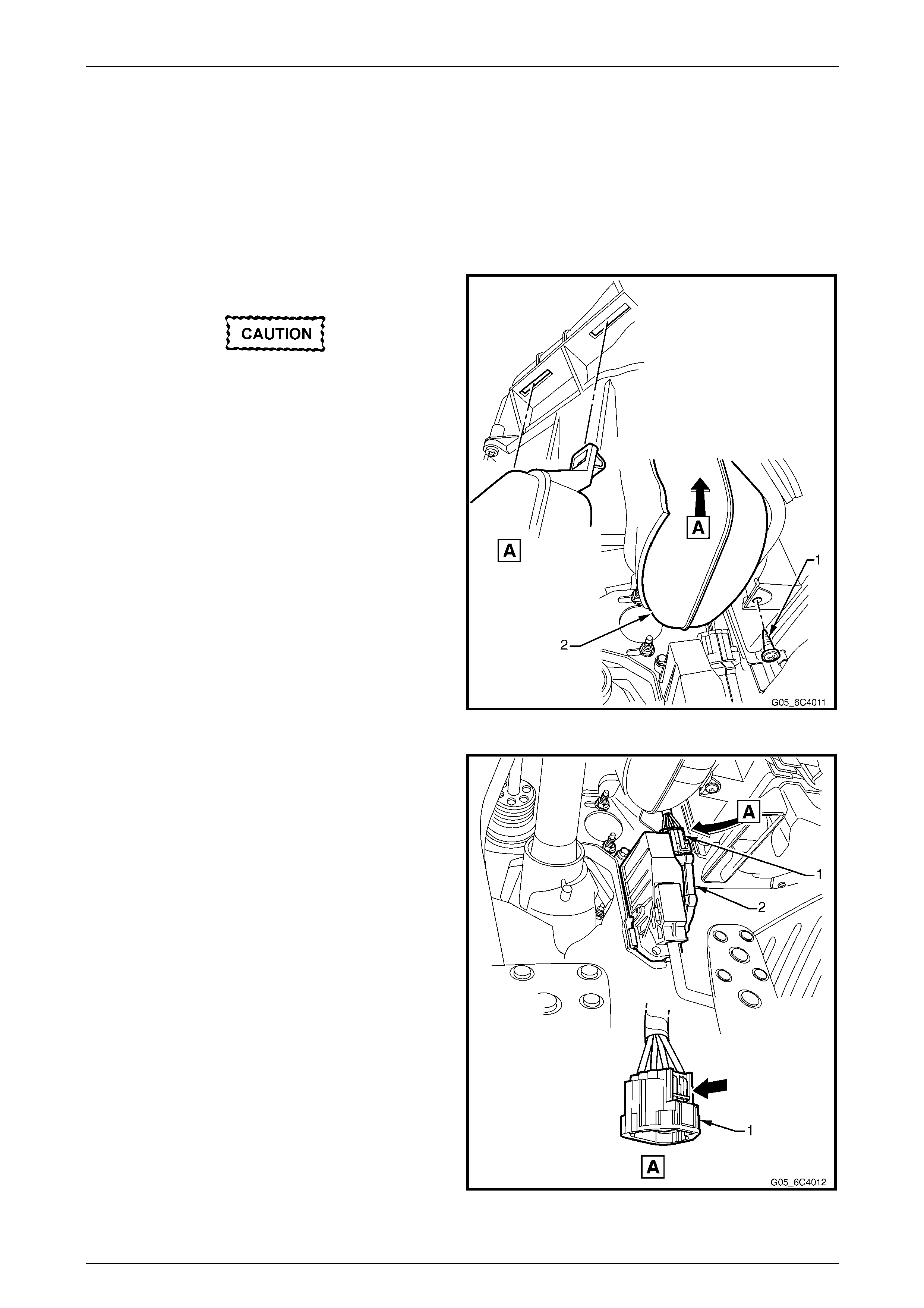
1 Turn the ignition switch off.
2 Remove the screw (1) retaining the vacuum tank (2).
Take care not to damage the hose connected
to the vacuum tank.
3 Manoeuvre the vacuum tank out from under the
instrument panel and place to one side.
Figure 6C4 – 1
NOTE
If difficulty is experienced in disconnecting the
harness connector from the A PP sensor, remove
the sensor from the APP support bracket and
then disconnect the harness c onnector.
4 Disconnect the wiring harness connector (1) from the
Accelerator Pedal Position (APP) sensor (2) by
depressing the latch in the direction of the ar row.
Figure 6C4 – 2
Engine Management – HSV - Gen IV V8 Page 6C4–4
Page 6C4–4
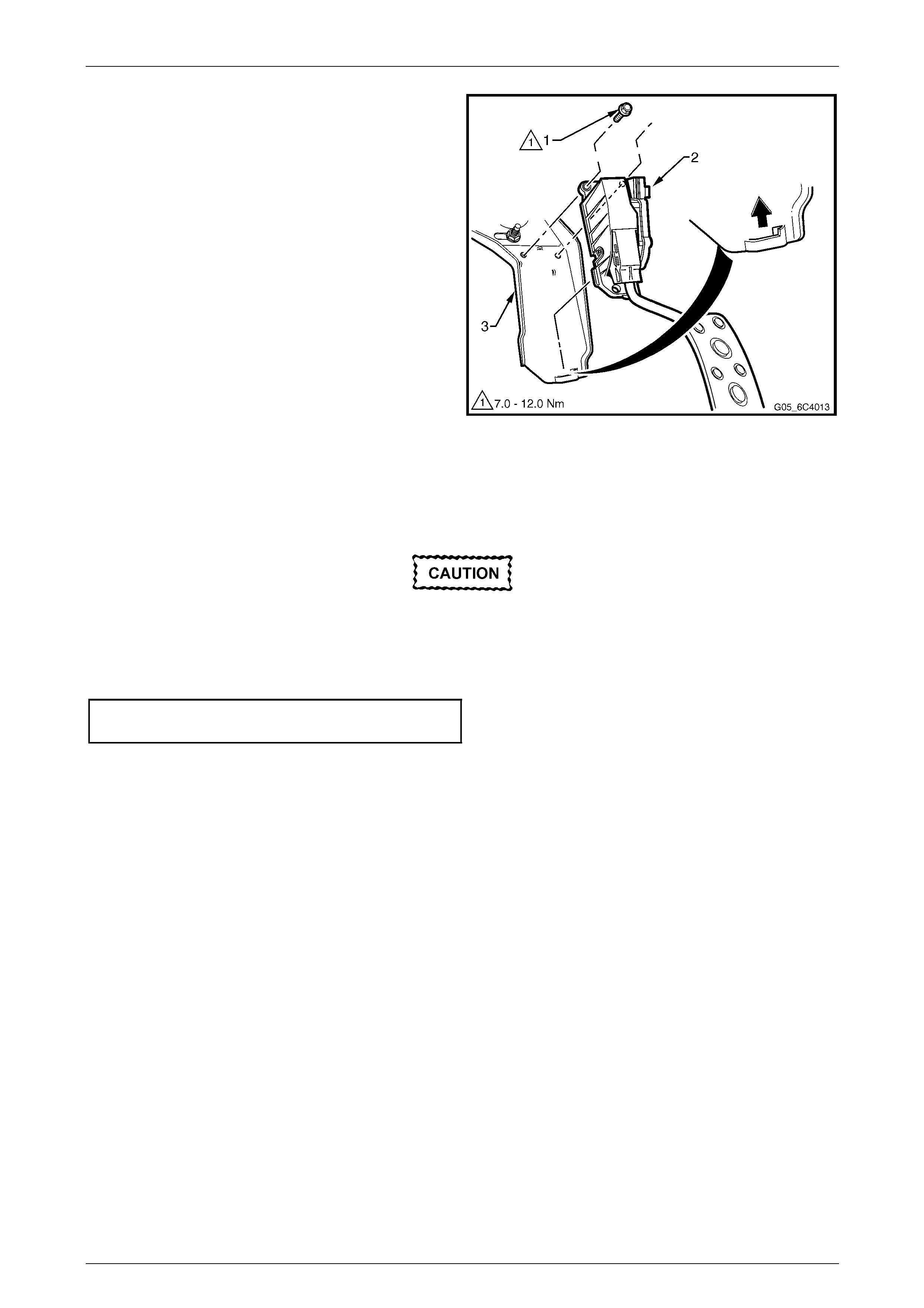
5 Remove the bolt (1) in two places, attaching the APP
sensor (2) to the Accelerator Pedal Position (APP)
sensor support bracket (3).
6 Slide the APP sensor upwards in the direction of the
arrow, to disengage the sensor from the support
bracket.
Figure 6C4 – 3
Reinstall
Reinstallation of the APP sensor is the reverse of the removal procedure, noting the following:
Make sure that the APP sensor engages the
APP support bracket, refer to Figure 6C4 – 3.
1 Reinstall the bolt, two places, attaching th e APP sensor to the supp ort bracket and tighten to the correct torque
specification.
APP sensor attaching bolt
torque specification...................................7.0 – 12.0 Nm
2 Road test the vehicle and check for correct operation.

Engine Management – HSV - Gen IV V8 Page 6C4–6
Page 6C4–6
1.3 Air Cleaner Assembly
Air Cleaner Upper Housing
Remove
1 Turn the ignition switch off.
2 Remove the upper radiator shroud, refer to Section 6B4 Eng ine Cooling – Gen IV V8 Engine.
3 Remove the air duct, refer to 1.9 Mass Air Flow (MAF) Sensor and Intake Air Duct.
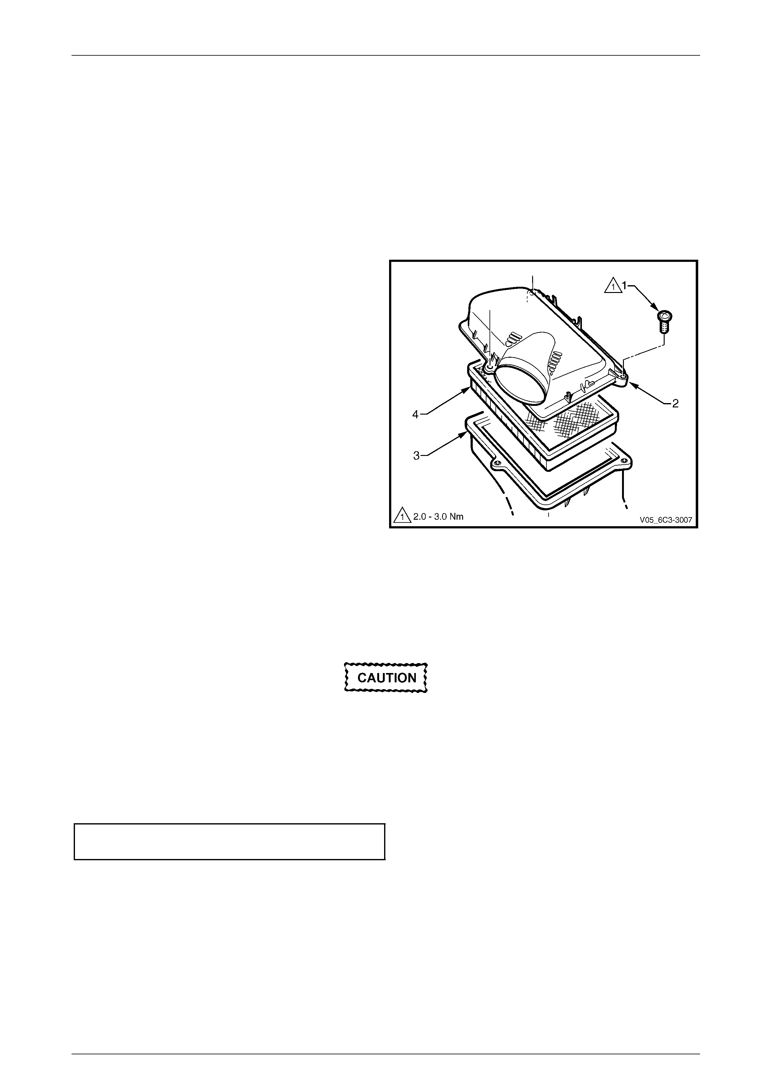
4 Remove the screw (1), three places, attaching the air
cleaner upper housing (2) to the air cleaner lower
housing (3).
5 Remove the upper housing and air cleaner
element (4).
Figure 6C4 – 4
Reinstall
Reinstallation of the air cleaner upper housing is the reverse of the remo val procedure, noting the foll owing:
1 Reinstall the air cleaner element.
Make sure that the air cleaner sealing rubber
is correctly located in the air cleaner lower
housing during installation. Failure to do this
may result in engine damage due to unfiltered
air entering the engin e air intake s ystem.
2 Reinstall the screw, in three places, attaching the air cleaner upper hous ing to the air cleaner lower housing an d
tighten to the correct torque specification.
Air cleaner upper housing attaching
screw torque specification...........................2.0 – 3.0 Nm
3 Road test the vehicle and check for correct operation, taking particular note that no air leaks are evident.
Engine Management – HSV - Gen IV V8 Page 6C4–7
Page 6C4–7
Air Cleaner Lower Housing
Remove
1 Turn the ignition switch off.
2 Remove the air cleaner upper housing as described previously.
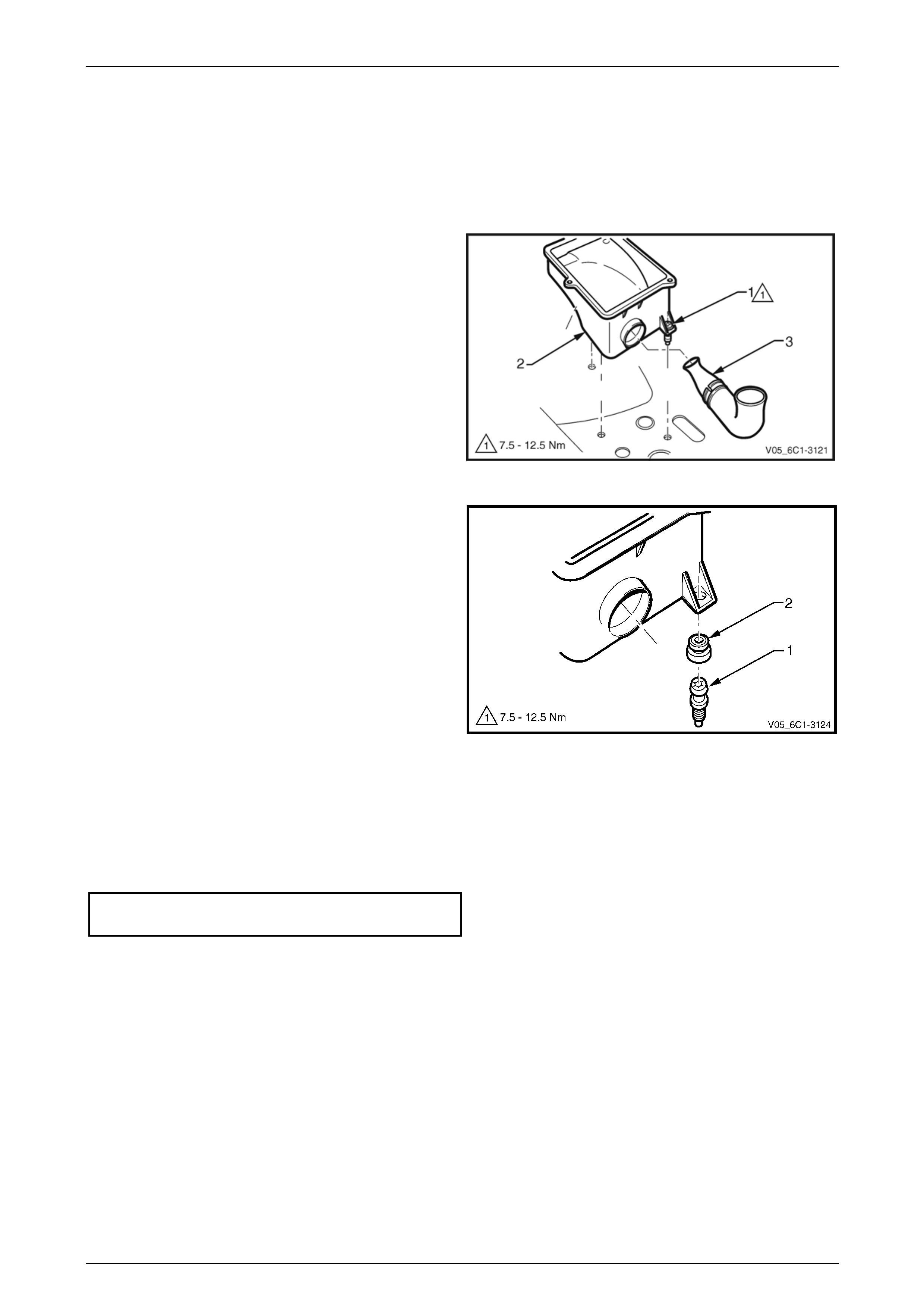
3 Fully loosen the stud (1), three places, attaching the
air cleaner lower housing (2) to the fender inner panel.
NOTE
The stud and air cleaner housing insulator are
removed with the air cleaner housing.
4 Disengage the air cleaner air inlet duct (3) from the
lower housing. Remove the lo wer ho using.
Figure 6C4 – 5
5 If required, remove the stud (1) and air cleaner
housing insulator (2) from the air cleaner lower
housing.
Figure 6C4 – 6
Reinstall
Reinstallation of the air cleaner assembly is the reverse of the removal procedure, noting the following:
1 Reinstall the stud, three places, attaching the air cleaner lo wer housing to the fender inner panel and tighten to the
correct torque specification.
Air cleaner lower housing attaching
stud torque specification ...........................7.5 – 12.5 Nm
2 Road test the vehicle and check for correct operation, taking particular note that no air leaks are evident.
Engine Management – HSV - Gen IV V8 Page 6C4–8
Page 6C4–8
1.4 Engine Control Module (ECM)
Service of the Engine Control Module (ECM) should normally consist of either replacement of the ECM, or ECM
programming. If the diagnostic proced ures call for the ECM to be replaced, the ECM should be first checked to ensure it
is the correct part. If it is, replace the faulty ECM.
• Do not touch the ECM connector pins as
Electrostatic Discharge (ESD) d amage may
result. For further information on ESD,
refer to Section 00 Warnings, Cautions and
Notes.
• When removing or reinstalling the ECM
harness connector/s, ensure that the
ignition switch is in the OFF position and
that the battery has been disconnected.
Failure to do so may result in damage to
the ECM and/or associated components.
• Disconnection of the battery affects
certain vehicle electronic systems. Refer
to Section 00 Warnings, Cautions and
Notes before disconnecting the battery.
Remove
1 Turn the ignition switch off.
2 Disconnect the battery, refer to Section 00 Warnings, Cautions and Notes.
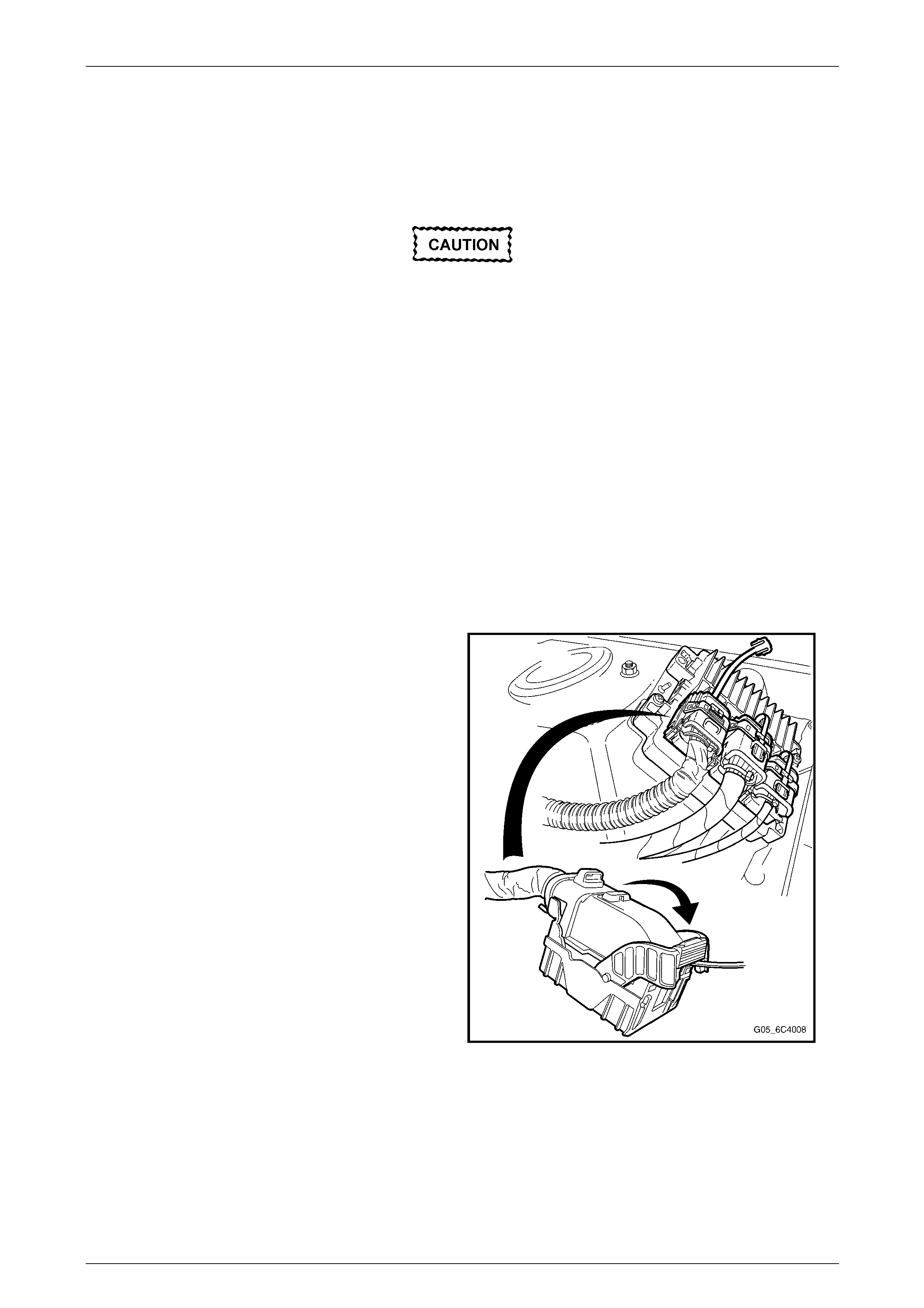
3 Remove the Connector Protection Assura nce (CPA)
locks on each ECM electrical connector, then move
the connector lock levers to the unlock position.
4 Disconnect the wiring harness connectors.
Figure 6C4 – 7
Engine Management – HSV - Gen IV V8 Page 6C4–9
Page 6C4–9
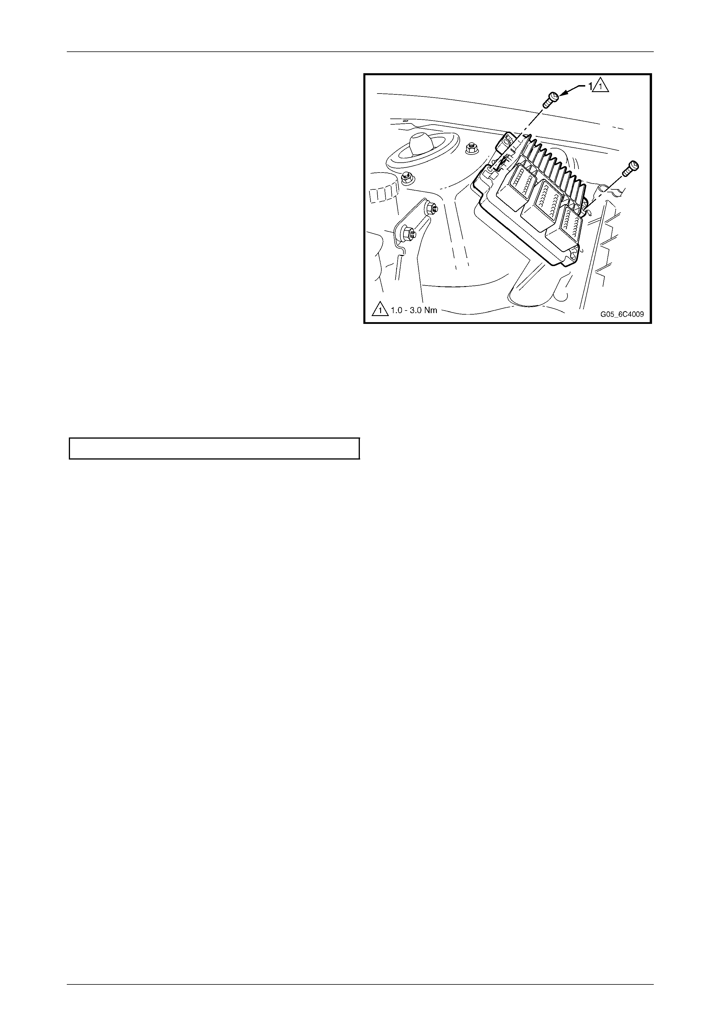
5 Remove the two screws (1) securing the ECM to the
mounting bracket
6 Remove the ECM.
Figure 6C4 – 8
Reinstall
Reinstallation is the reverse of the removal procedure, noting the following:
1 Reinstall the ECM scre ws, and tighten to the correct torque specification.
ECM retaining screw torque specification.........1 – 3 Nm
2 If the ECM has been replaced, perform the following proced ures:
• ECM service programming, refer to Section 0C Tech 2.
• ECM/PIM/BCM security link, refer to Section 0C Tech 2.
• Main diagnostic functional check.
3 If the ECM has been removed, but not replaced, perform the main diagnostic table functional check.
Engine Management – HSV - Gen IV V8 Page 6C4–10
Page 6C4–10
1.5 Engine Control Module (ECM) Bracket
Assembly
Remove
1 Remove the ECM, refer to 1.4 Engine Control Module (ECM).
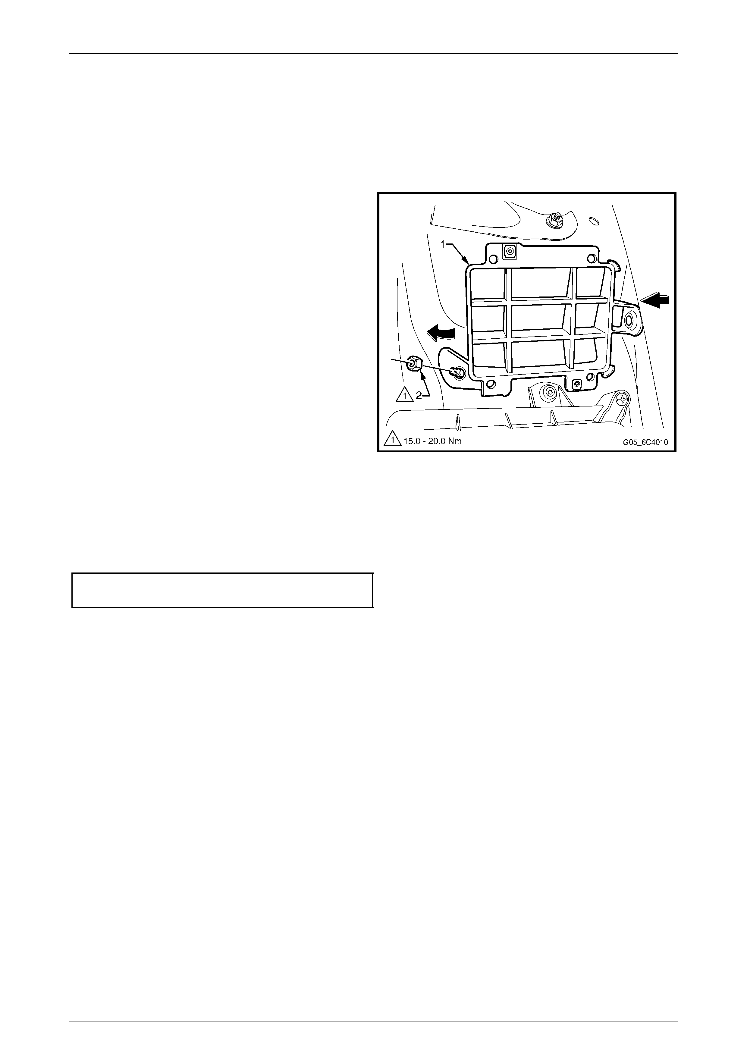
2 Remove nut (2) securing the ECM bracket (1) to the
body.
3 Remove the ECM mounting bracket by lifting up and
away from the body.
Figure 6C4 – 9
Reinstall
Reinstallation of the ECM mounting bracket is the reverse of the removal procedure, notin g the following:
Tighten the nuts attaching the ECM mounti ng bracket to the bod y to the correct torque specification.
ECM mounting bracket attaching
nut torque specification.................................15 – 20 Nm
Engine Management – HSV - Gen IV V8 Page 6C4–11
Page 6C4–11
1.6 EVAP Canister Purge Solenoid Valve
Remove
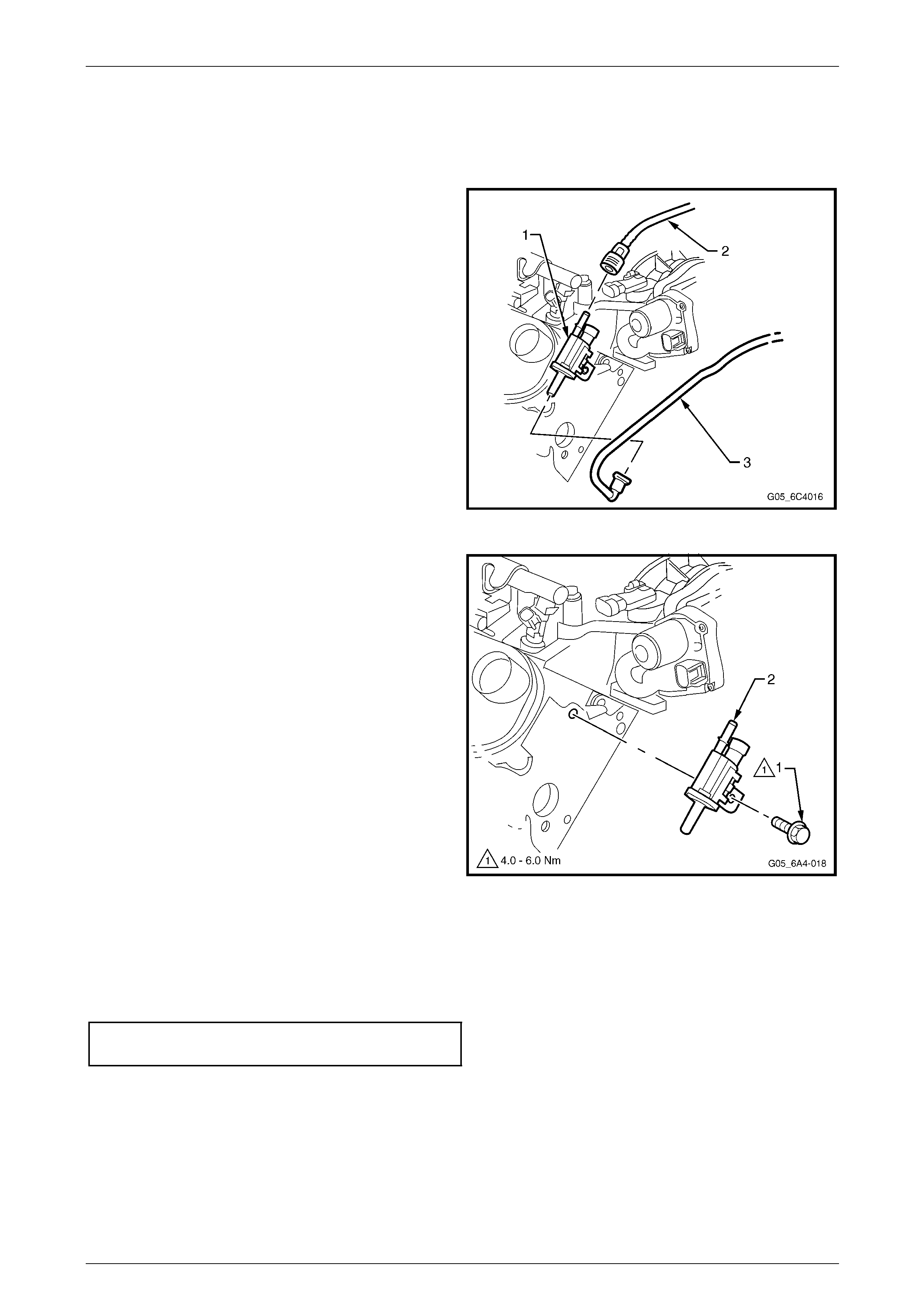
1 Disconnect the electrical connector from the EVAP
purge solenoid (1).
2 Disconnect the inlet hose (2) by squeezing the
retaining clip and pulling the hose from the solenoid.
3 Disconnect the outlet hose (3) from the purge solenoid
using tool AU533, refer to Section 8A Fuel System.
Figure 6C4 – 10
4 Remove the bolt (1) from the EVAP purge solenoid
mounting bracket and remove the EVAP purge
solenoid valve (2) and bracket.
Figure 6C4 – 11
Reinstall
Reinstallation of the EVAP canister pur ge solenoid valve is the reverse of the removal procedure, noting the follo wing:
Tighten the bolt attaching the EVAP canister purge solenoid valve to the engin e to the corr ect torque specification.
EVAP canister purge solenoid valve attaching
bolt torque specification....................................4 – 6 Nm
Engine Management – HSV - Gen IV V8 Page 6C4–12
Page 6C4–12
1.7 Heated Oxygen Sensors (HO2S)
To avoid the possibility of personal injury,
allow the exhaust pipe to cool to ambient
temperature (less than 50° C) before
attempting to remove the oxygen sensor.
Service Precautions
• Handle the oxygen sensor carefull y. Do not drop it, and keep it free of grease, dirt and other contaminants. Do not
use cleaning solvents of any type on the sen s or.
• Do not repair the sensor or any of its parts, including the wiring and connector. Replace the oxygen sens or if any
damage is evident.
• The oxygen sensor may be di fficult to remove when the engine is cold. Excessive force may damage the threads in
the exhaust manifold or exhaust pipe.
• If the oxygen sensor has been removed, but not replaced, then anti-seize compound must be appl ied to the
threads prior to installation. New oxygen sensors will already have the a nti-seize compound appli ed.
Remove
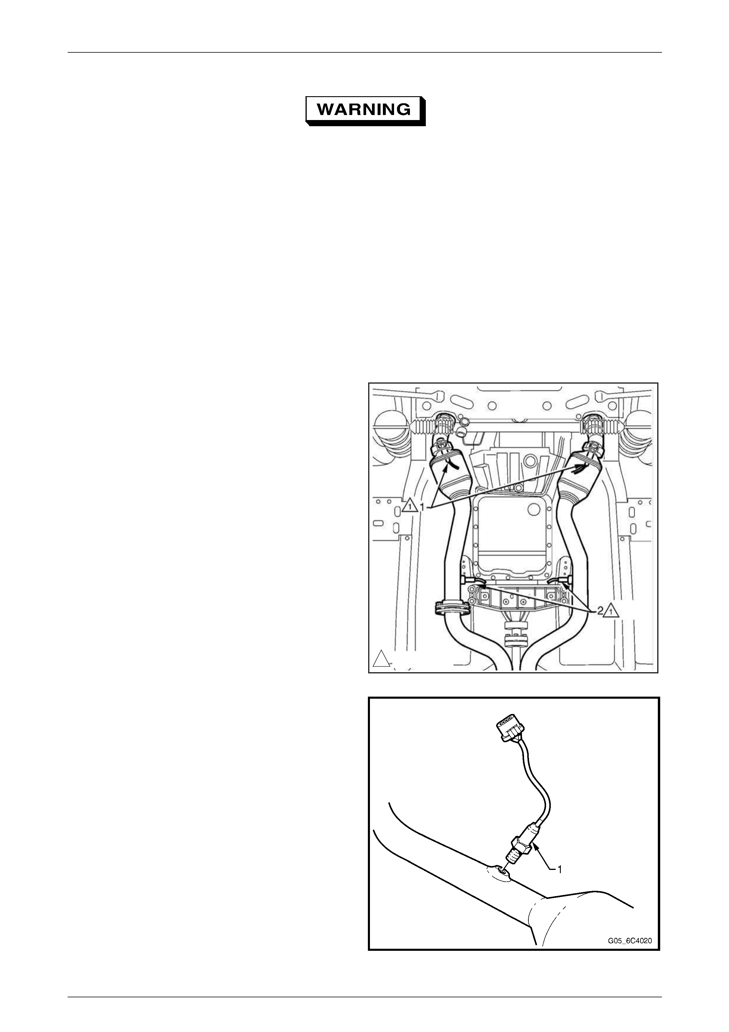
NOTE
It may be necessary to lower the exhaust system
to gain sufficient access to the front HO2S (1)
and/or its connector, refer to
Section 8B Exhaust System.
1 Raise the front of vehicle and support on safety
stands, refer to Section 0A General Information for the
location of jacking and support points.
138-48Nm
Figure 6C4 – 12
2 Disconnect the electrical connector from the HO2S (1)
to be removed.
3 Loosen and carefully remove the HO2S from the
exhaust pipe.
Figure 6C4 – 13
Engine Management – HSV - Gen IV V8 Page 6C4–13
Page 6C4–13
Reinstall
Reinstallation is the reverse of the removal procedure, noting the following:
A special anti-seize compound is used on the
heated oxygen sensor threads. New oxygen
sensors will already have the anti-seize
compound applied to the threads.
If an oxygen sensor has been removed, but
not replaced, then anti-seize compound must
be applied to the threads prior to installation.
1 Coat the cleaned threads of the sensor with anti-seize compound, part number 1237 7953. Specified anti-seize
compound is availabl e from authorised retailer parts outlets as part number 5613695.
2 Tighten the HO2S to the correct torque specificatio n.
HO2S torque specification ......................38.0 – 48.0 Nm
3 Road test the vehicle and check for correct operation, taking particular note that no exhaust leakage is evident.
Test
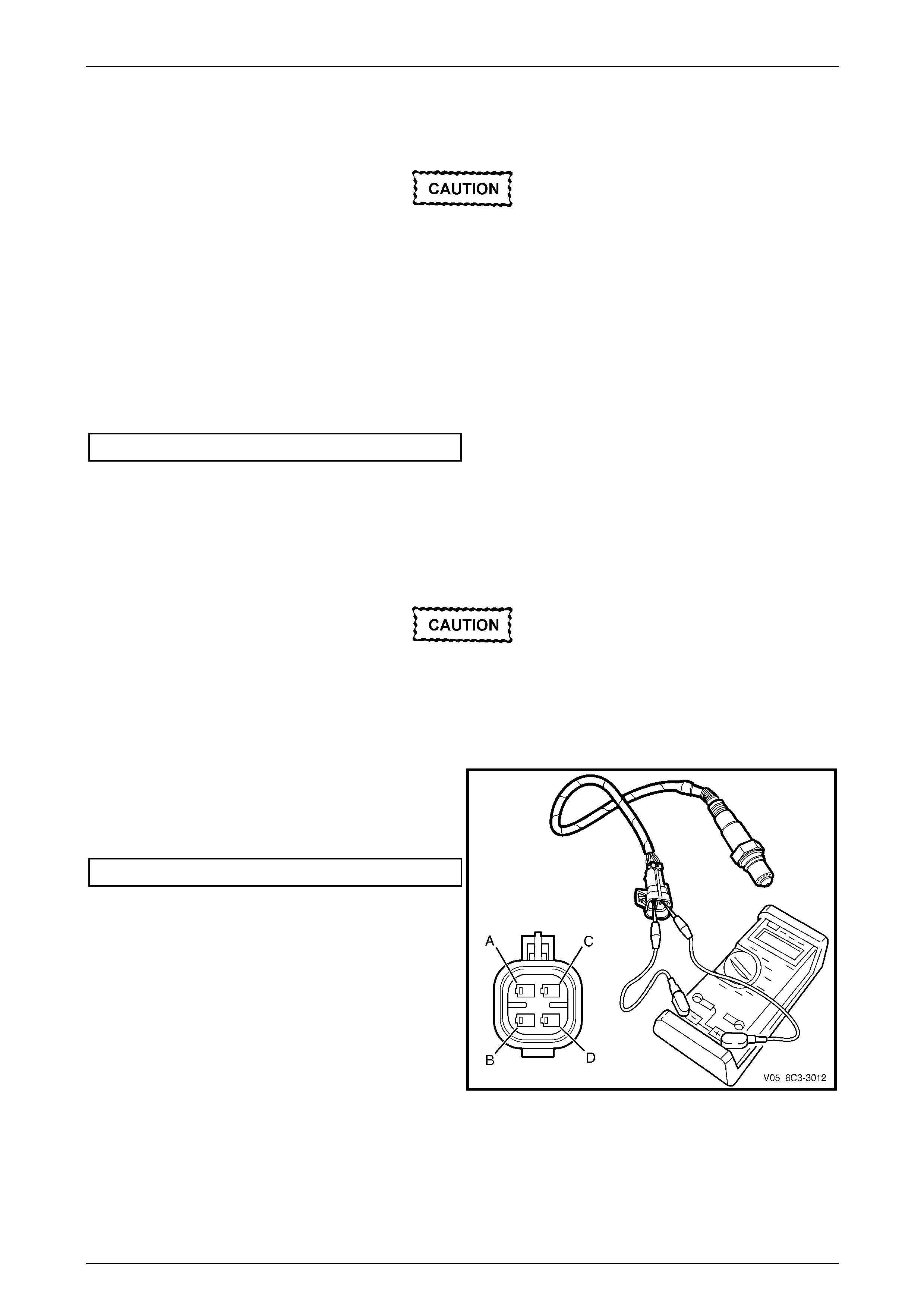
Front Sensors
• Under no circumstances should battery
voltage be applied to the HO2S heater.
• To prevent component damage use
connector test adaptor kit J 35616-A.
Heater Resistance Check
1 Using a digital ohmmeter and connector test adaptor
kit J 35616-A, measure the resistance acr oss
terminals C and D.
2 Compare the reading against the specification.
HO2S heater resistance @ 20° C........................ TBA Ω
3 If the resistance is not within specification, replace the
HO2S.
Figure 6C4 – 14
Engine Management – HSV - Gen IV V8 Page 6C4–14
Page 6C4–14
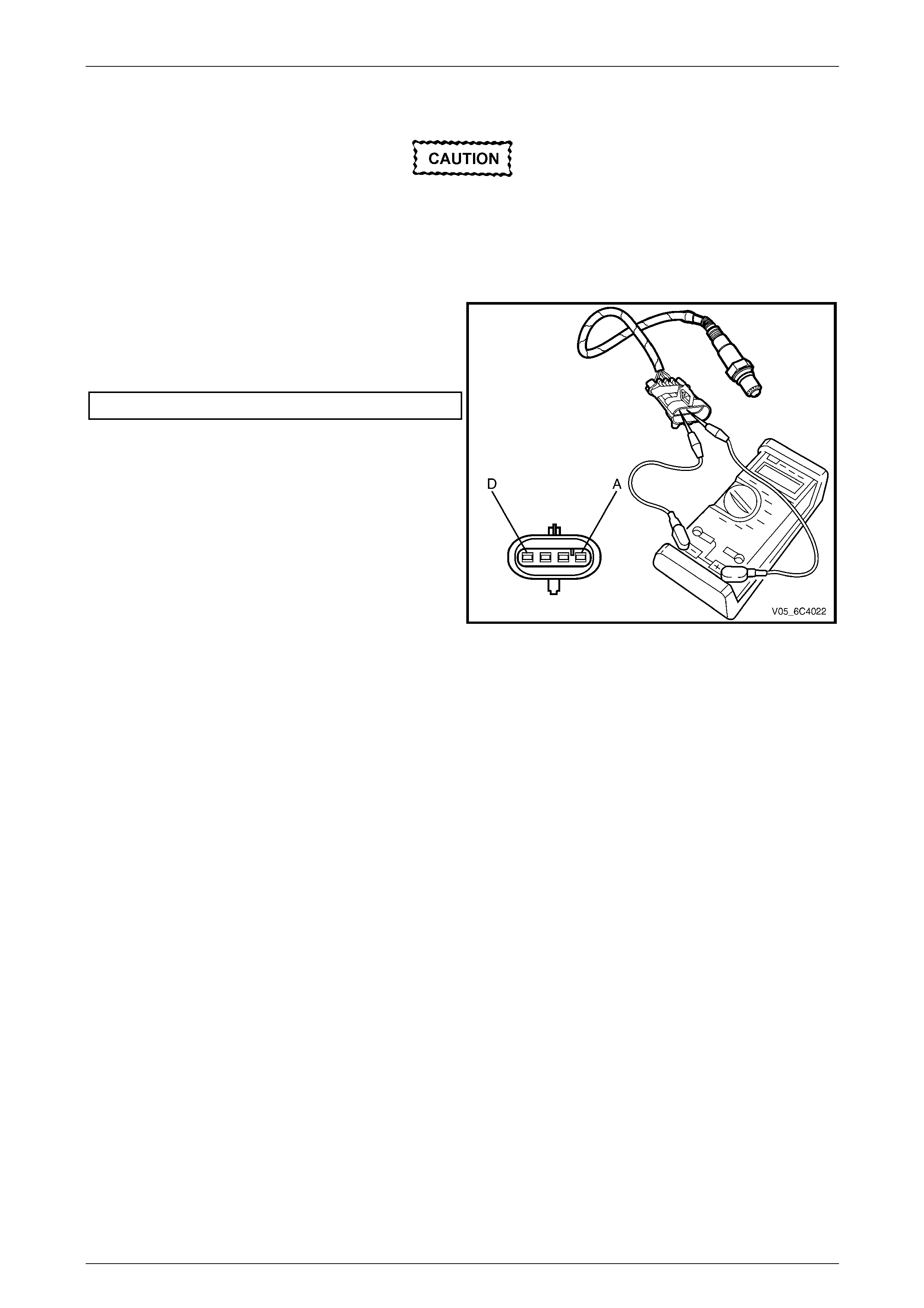
Rear Sensors
• Under no circumstances should battery
voltage be applied to the HO2S heater.
• To prevent component damage use
connector test adaptor kit J 35616-A.
Heater Resistance Check
1 Using a digital ohmmeter and connector test adaptor
kit J 35616-A, measure the resistance acr oss
terminals C and D.
2 Compare the reading against the specification.
HO2S heater resistance @ 20° C........................ TBA Ω
3 If the resistance is not within specification, replace the
HO2S.
Figure 6C4 – 15
Engine Management – HSV - Gen IV V8 Page 6C4–15
Page 6C4–15
1.8 Intake Air Temperature (IAT) Sensor
The Intake Air Temperature (IAT) sensor is part of the MAF sensor assembly, refer to
1.9 Mass Air Flow (MAF) Sensor and Intake Air Duct for the replacement procedure.
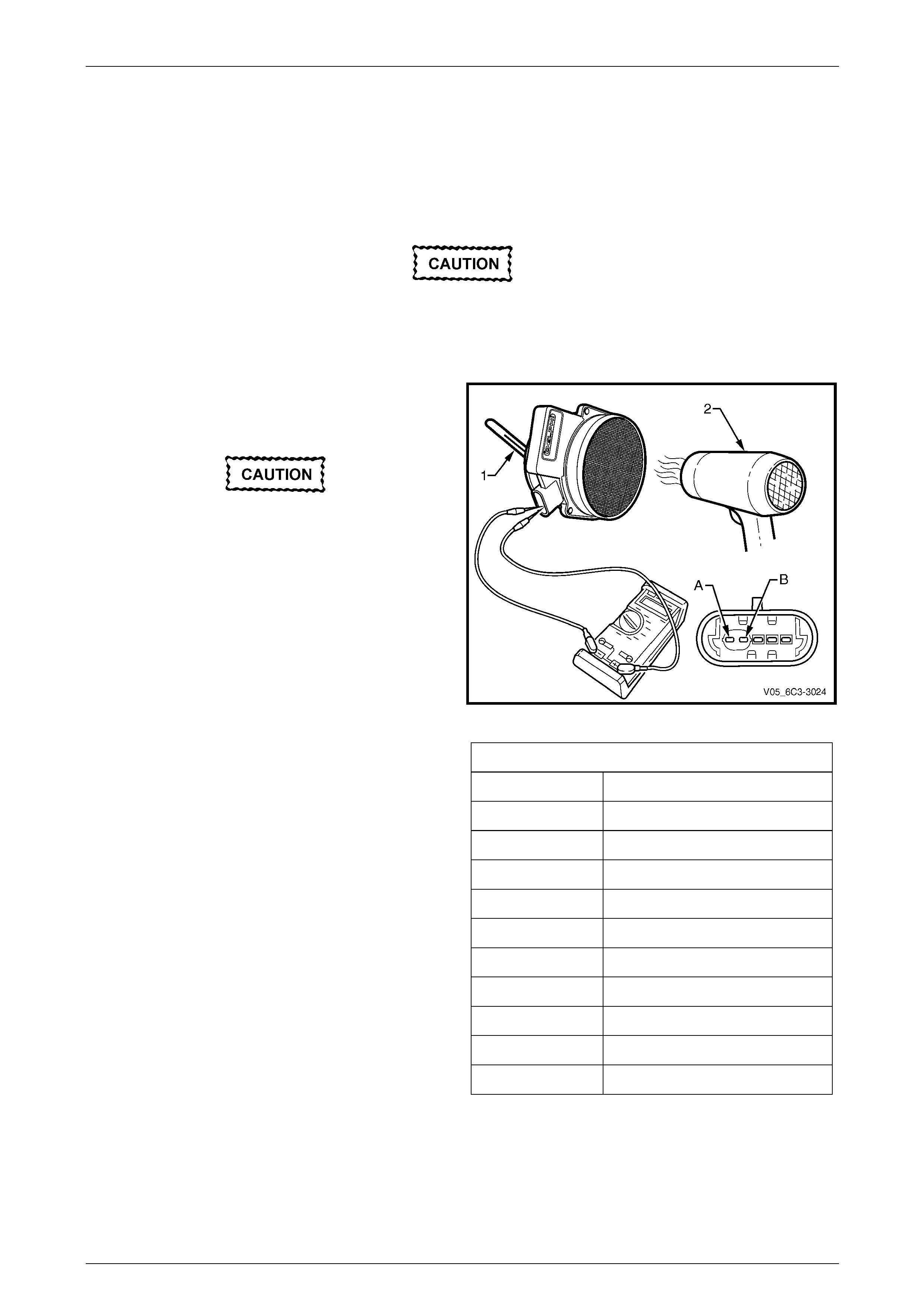
Test
To prevent component damage use connector
test adaptor kit J 35616-A.
Resistance Check
1 Connect a digital ohmmeter using connector test
adaptor kit J 35616-A to the Mass Air Flow (MAF)
sensor across terminals (A) and (B).
Do not use a high temperature heat gun as
damage to the MAF sensor will result.
2 Whilst holding a thermometer (1), use a commercially
available hair dryer (2) to blow warm air through the
MAF sensor.
Figure 6C4 – 16
3 Observe the resistance values as the temperature
increases and compare t he temperature/resistance
change to the specifications.
4 If the resistance is not within specifications, replace
the MAF sensor.
Intake Air Temperature Vs Resistance
Temperature °C Resistance – Ohms (Ω)
-10 16180
0 9420
20 3520
25 2796
40 1459
60 667
80 332
100 177
120 100
140 60
Engine Management – HSV - Gen IV V8 Page 6C4–16
Page 6C4–16
1.9 Mass Air Flow (MAF) Sensor and Intake
Air Duct
Remove
1 Remove the upper radiator shroud, refer to Section 6B4 Eng ine Cooling.
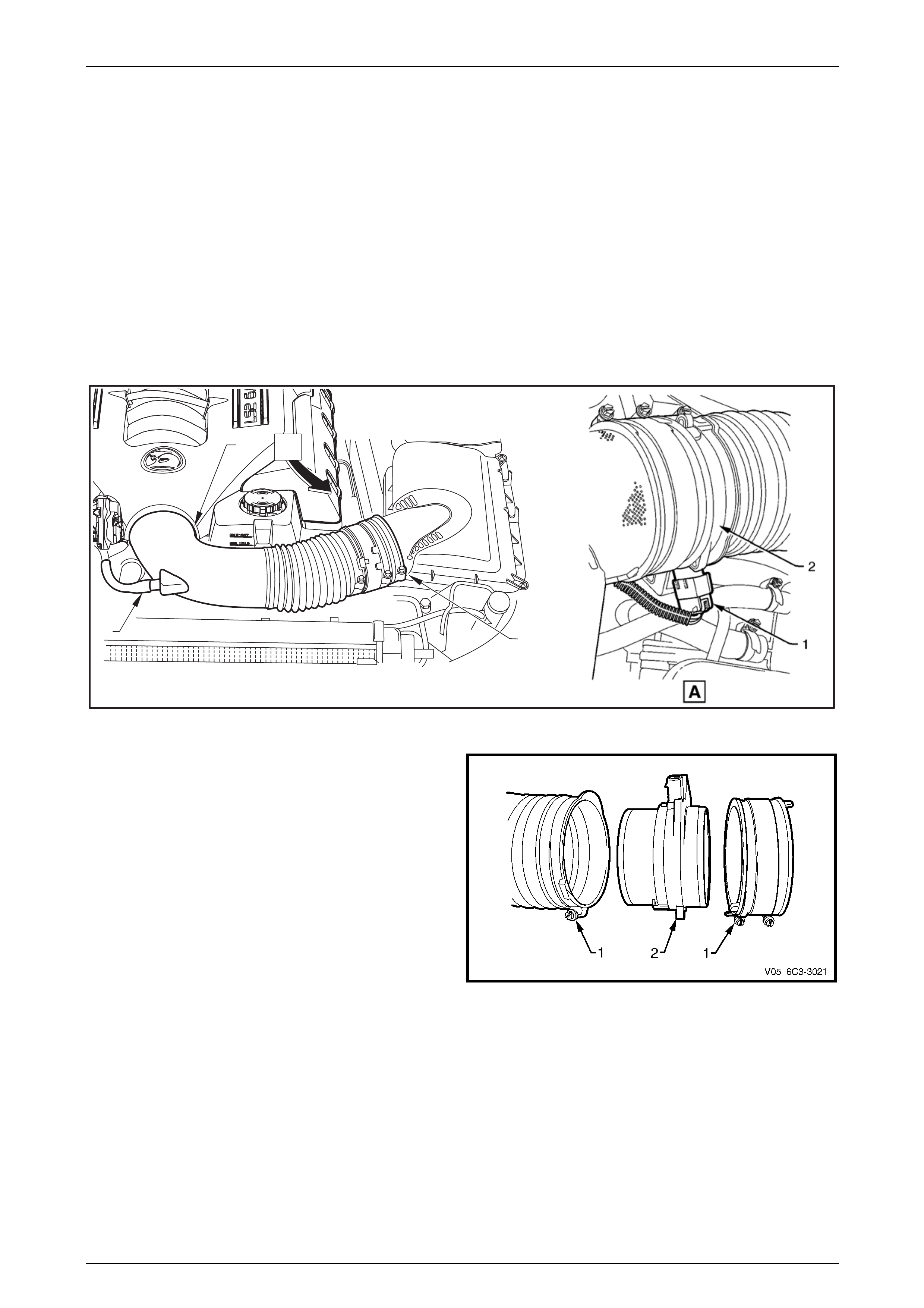
2 Remove the intake air duct:
a Lift up the security tang on the MAF sensor wiring harness conn ector (1) and remove the connector from
sensor (2), refer to Figure 6C4 – 17.
b Disconnect the PCV hose (3) from the intake air duct.
c Loosen the clamps (4) at eac h end securing the intake air duct to the throttle body and the air cleaner upper
housing. Remove the duct.
A
3
4
4
Figure 6C4 – 17
3 Loosen the two clamps (1) securing the air intake duct
and the air duct adaptor to the MAF sensor (2).
Figure 6C4 – 18

Engine Management – HSV - Gen IV V8 Page 6C4–17
Page 6C4–17
Reinstall
Reinstallation of the MAF sensor is the reverse of the removal procedure, noting the following:
NOTE
• The embossed arrows on the MAF sensor
indicate the correct air flow direction. The
arrows must point towards the engine.
• The air duct adaptor (between air cleaner and
MAF sensor), retaining clamps, air duct and
MAF sensor, all have locating notches.
Ensure all notches are aligned.
1 Reinstall the retaining clamps, aligning notches, tighten cla m ps to the specified torque.
Intake Air Duct Clamp
Torque Specification ...................................1.5 – 2.5 Nm
2 Start vehicle and check for air leaks.
Engine Management – HSV - Gen IV V8 Page 6C4–18
Page 6C4–18
1.10 Throttle Body
Handling Precautions
Under no circumstances should the throttle
body be disassembled. If the throttle body is
disassembled, the vacuum seal between the
cover plate and the throttle body will be
broken. This will allow the ingress of foreign
particles and or moisture and render the
throttle body unserviceable.
The throttle body must not be subjected to
any form of shock such as dropping it. If the
throttle body is subjected to shock, damage
may result to the fragile motor magnets within
the throttle body.
Remove
1 Turn the ignition switch off.
2 Remove the intake air duct, refer to 1.9 Mass Air Flow (MAF) Sensor and Intake Air Duct.
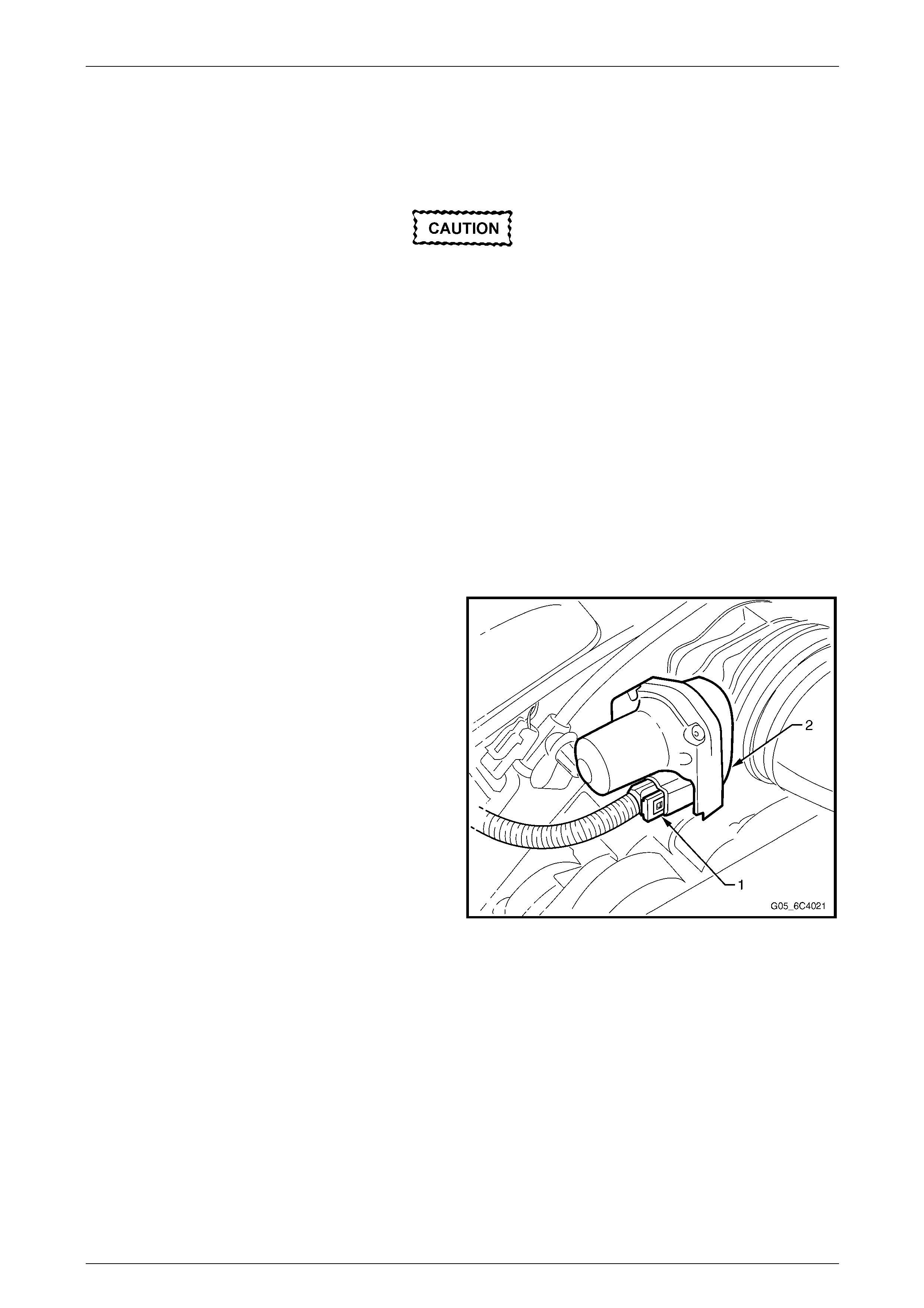
3 Disconnect the throttle body electrical connector (1)
from the throttle body (2).
Figure 6C4 – 19
Engine Management – HSV - Gen IV V8 Page 6C4–19
Page 6C4–19
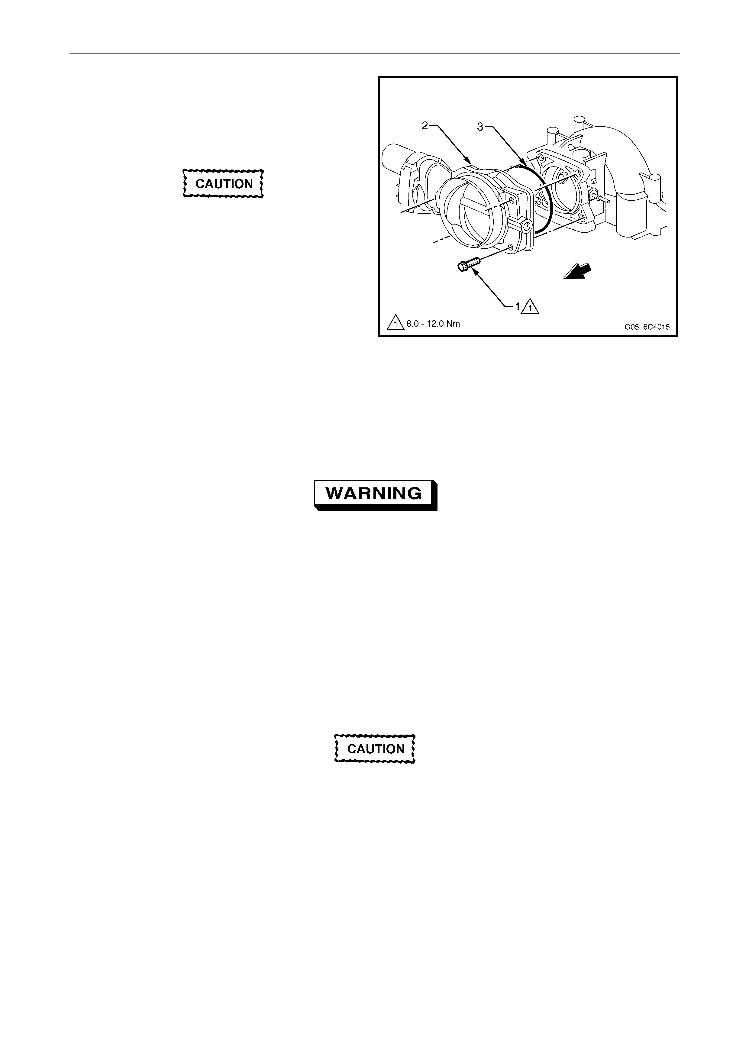
4 Remove the bolts (1), four places, attaching the
throttle body (2) to the inlet manifold.
5 Remove the throttle body and the seal (3).
6 Discard the removed seal.
• To prevent damage to the sealing
surfaces, it is preferred that only plastic
scrapers are used for cleaning deposits
from machined alloy surfaces.
• Do not soak the throttle body in cold
immersion type cleaner. To clean the
throttle body following disassembly, use
a spray type cleaner such as GM 1052626
or equivalent. Use a shop towel to remove
heavy deposits.
• The throttle body contains electrical
components that should not come in
contact with solvent or cleaner, as
damage may result.
7 Clean both of the sealing surfaces.
Figure 6C4 – 20
Inspect
To avoid serious personal injury, never
attempt to rotate the throttle plate manually
whilst the throttle body harness connector is
connected to the throttle bod y.
The following throttle body inspection procedure may be carried o u t with the throttle body installed on the vehicle. Prior to
performing a throttle body on-v ehicle inspection, perform the following:
1 Switch the ignition off.
2 Disconnect the throttle body harness conn ector.
3 Remove the air cleaner intake duct, refer to 1.9 Mass Air Flow (MAF) Sensor and Intake Air Duct.
4 Fully open the throttle plate by hand in order to inspect the throttle body bore and the thr ottle plate for a ny deposits.
When cleaning / inspecting the throttle body:
• Do not subject the throttle body assembly
to an immersion cleaner or a strong
solvent. Damage to the throttle position
sensor and / or sealed throttle shaft
bearings will result.
• Never use a wire brush or scraper to clean
the throttle body. A wire brush or sharp
tool may damage the throttle body
components.
5 Use a clean shop towel and GM cleaner 105 2626 or equivalent product to clean the throttle body bore and throttle
plate. If necessary, use a parts cleaning brush in order to remove heavy deposits.
6 To inspect the throttle body for a binding throttle plate, fully open and close the throttle plate by hand. The throttle
plate should open and close smoothly.

Engine Management – HSV - Gen IV V8 Page 6C4–20
Page 6C4–20
7 Inspect the throttle body for a bent or damaged throttle plate, and cracks, corrosion, or distortion in the throttle body
housing.
NOTE
The throttle body contains no serviceable parts
and should not be disassembled. If the throttle
body is damaged it must be replaced as an
assembly.
8 If the throttle body is affected by any of the above conditions, the throttle body must be re placed.
9 If an on-vehicle throttle body inspection was performed, reinstall the air cleaner intake d uct, refer to
1.9 Mass Air Flow (MAF) Sensor and Intake Air Duct.
10 Road test the vehicle and check for correct operation, taking particular note that no air leaks are evide nt.
Reinstall
Reinstallation of the throttle bod y is the reverse of the removal procedure, noting the foll owing:
1 Install a new throttle body seal .
2 Reinstall the throttle body attaching bolts and tighten to the correct torque specification.
Throttle body attaching bolt
torque specification...................................8.0 – 12.0 Nm
3 Road test the vehicle and check for correct operation, taking particular note that no air leaks are evident.
Engine Management – HSV - Gen IV V8 Page 6C4–21
Page 6C4–21
1.11 Camshaft Position (CMP) Sensor
Replacement
Removal Procedure
1 Remove the generator bracket assembly. Refer to
Generator Bracket Replacement in Engine Electrical.
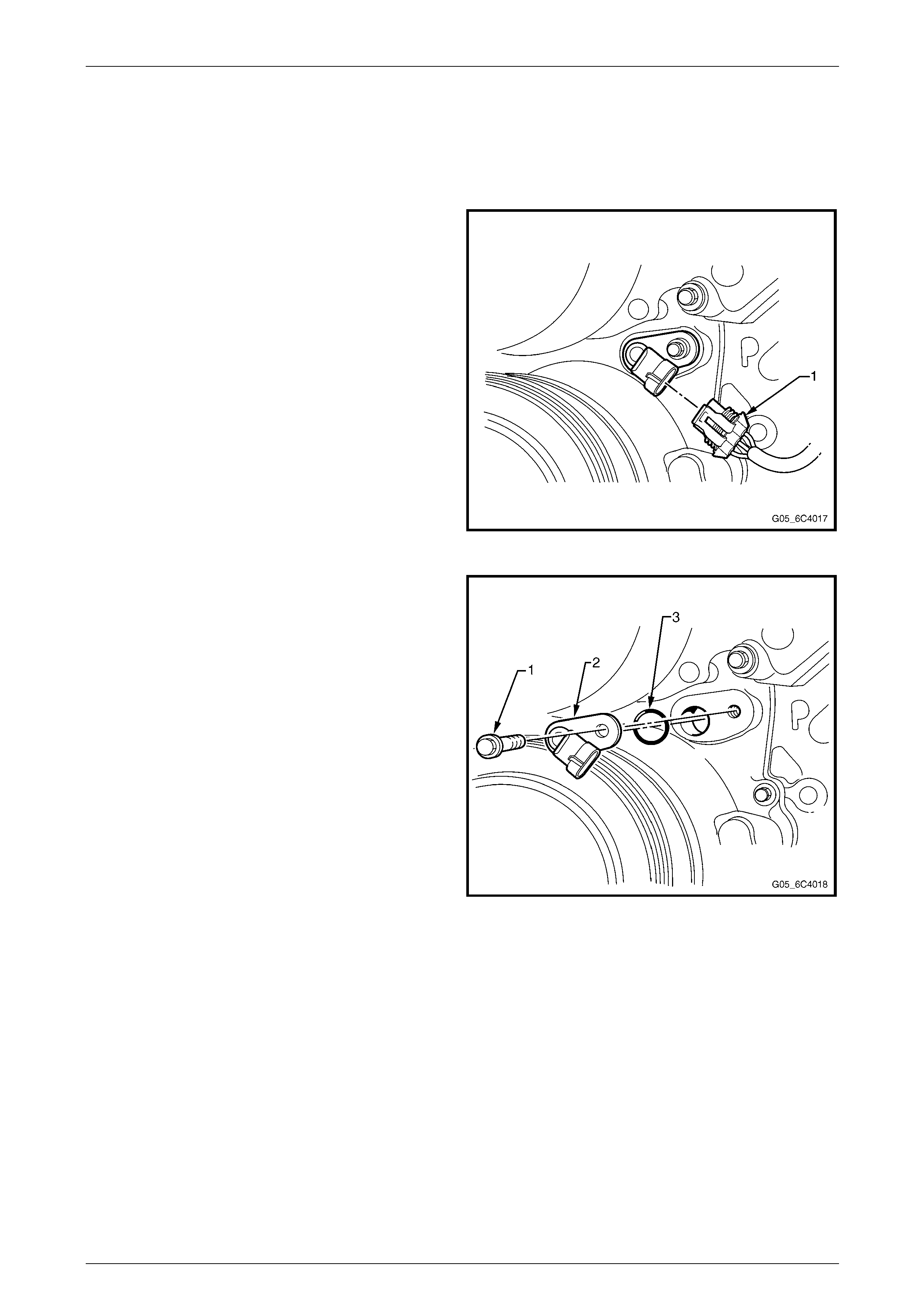
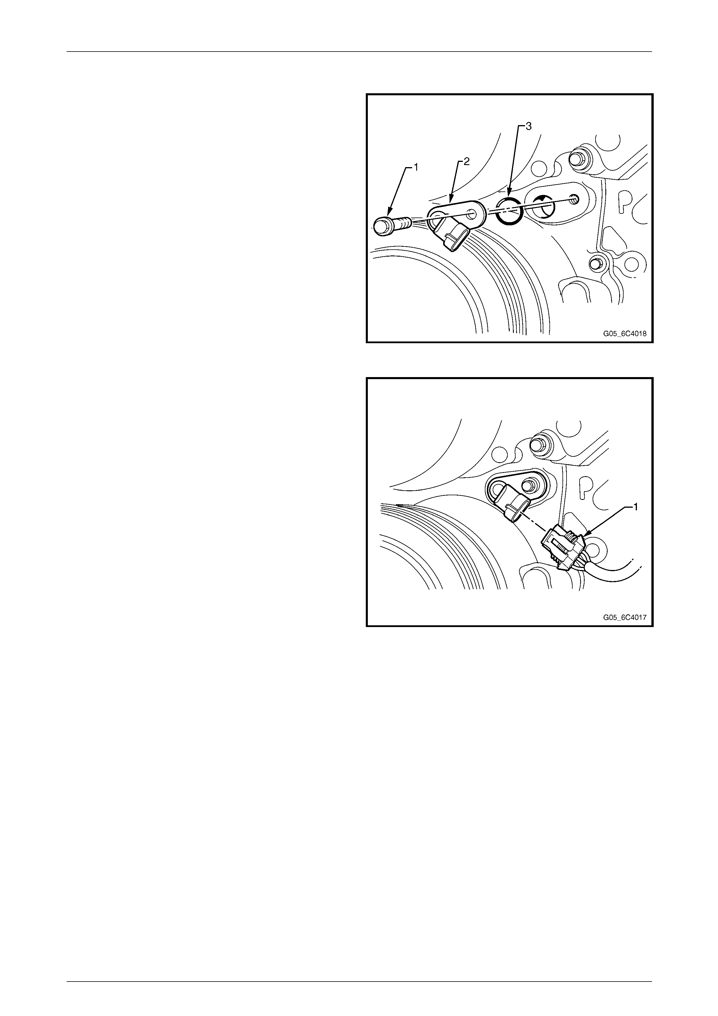
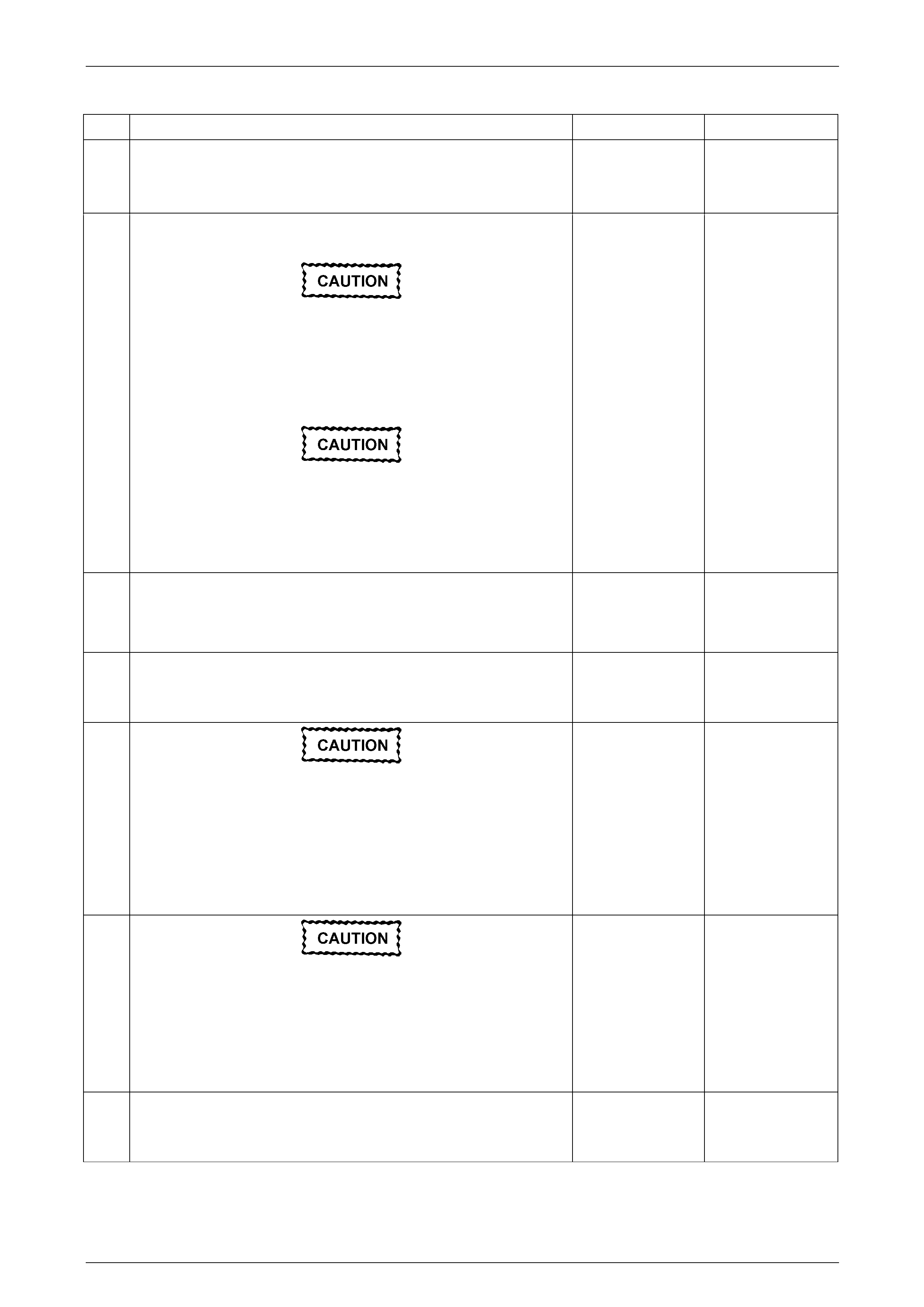
2 Disconnect the camshaft position sensor electrical
connector (1).
Figure 6C4 – 21
3 Remove the camshaft position sensor mounti ng bolt
(1).
4 Remove the camshaft position sensor assembl y (2, 3)
from the engine front cover.
Figure 6C4 – 22
Engine Management – HSV - Gen IV V8 Page 6C4–22
Page 6C4–22
Installation Procedure
Important: Before installing the camshaft sensor assembly,
apply a small amount of clean motor oil to the O-ring (3).
1 If removed, install the O-ring onto the camshaft positio n
sensor.
2 Install the camshaft position sensor assembly into the
engine front cover.
Notice: Refer to Fastener Notice in Section 00 Cautions and
Notices.
3 Install the camshaft position sensor mounting bolts.
Tighten
Tighten the camshaft position mountin g bolts to 25 N·m
(18 lb ft).
Figure 6C4 – 23
4 Reconnect the camshaft sensor electric al connector
(1).
5 Install the generator bracket assembly. Refer to
Generator Bracket Replacement in Engine Electrical.
Figure 6C4 – 24

Engine Management – HSV - Gen IV V8 Page 6C4–23
Page 6C4–23
2 Fastener Tightening
Specifications
Specifications
Application Metric English
Accelerator Pedal Position Sensor Attaching Bolts 7 - 12 Nm 62 - 106 lb in
Air Cleaner Lower Housing Securing Bolts 7.5 - 12.5 Nm 66 - 111 lb in
Air Cleaner Upper Housing Securing Screws 2 - 3 Nm 17 - 22 lb in
A/C Refrigerant Pressure Sensor 6 Nm 53 lb in
Camshaft Position (CMP) Sensor Bolt 25 Nm 18 lb ft
Crankshaft Position (CKP) Sensor Bolt 25 Nm 18 lb ft
Engine Coolant Temperature (ECT) Sensor 20 Nm 15 lb ft
Evaporative Emissions (EVAP) Canister Retaining Nut 6 Nm 53 lb in
Evaporative Emissions (EVAP) Purge Solenoid Retaining Bolt 4 - 6 Nm 35 - 53 lb in
Fuel Pump And Sender Assembly Ground Terminal Nut 7 Nm 62 lb in
Fuel Filler Pocket Fastening Nut 5 Nm 44 lb in
Fuel Fill Hose Clamps 2.5 Nm 20 lb in
Fuel Pipe Shield Nuts and Bolts 5 Nm 44 lb in
Fuel Rail Attaching Bolts 10 Nm 89 lb in
Fuel Tank Strap Upper Fastening Nut 20 Nm 15 lb ft
Fuel Tank Strap Lower Fastening Nut 40 Nm 30 lb ft
Heated Oxygen Sensor (HO2S) 38 - 48 Nm 28 - 35 lb ft
Ignition Coil Mounting Bolt 12 Nm 106 lb in
Knock Sensor (KS) Attaching Bolt 20 Nm 15 lb ft
Intake Air Duct Clamp 1.5 - 2.5 Nm 13 - 20 lb in
Engine Control Module (ECM) Mounting Fastener 1 - 3 Nm 9 - 22 lb in
Engine Control Module (ECM) Mounting Bracket Assembly Fastener 15 - 20 Nm 11 - 15 lb ft
Spark Plug New Cylinder Head 20 Nm 15 lb ft
Spark Plug Old Cylinder Head 15 Nm 11 lb ft
Throttle Body Attaching Bolts 8 - 12 Nm 70 - 106 lb in

Engine Management – HSV - Gen IV V8 Page 6C4–24
Page 6C4–24
3 MY2004 HSV VZ LS2 Diagnostic
Trouble Codes
Automatic Manual
Index P-Code P-Code Description Software Identifier Type Light Type Light
1 P0016
Crankshaft Position (CKP)-Camshaft
Position (CMP) Correlation Bank 1
Sensor A CeDFIR_e_CKP_ToCMP_A_CorrB1 B 1 B 1
5 P0030 Heater Control Bank 1 Sensor 1 CeDFIR_e_O2S_HtrCktB1S1 B 1 B 1
6 P0036 Heater Control Bank 1 Sensor 2 CeDFIR_e_O2S_HtrCktB1S2 B 1 B 1
7 P0050 Heater Control Bank 2 Sensor 1 CeDFIR_e_O2S_HtrCktB2S1 B 1 B 1
8 P0056 Heater Control Bank 2 Sensor 2 CeDFIR_e_O2S_HtrCktB2S2 B 1 B 1
9 P0068
MAP/MAF - Throttle Position
Correlation - Type "a" per Colin
Roberts CeDFIR_e_MAP_MAF_TP_Corr A 1 A 1
10 P0101 Air Flow Circuit Range/Performance
Problem CeDFIR_e_MAF_SnsrPerf B 1 B 1
11 P0102 Air Flow Circuit Low Input CeDFIR_e_MAF_SnsrCktLo B 1 B 1
12 P0103 Air Flow Circuit High Input CeDFIR_e_MAF_SnsrCktHi B 1 B 1
13 P0106 MAP/Barometric Pressure
Range/Perform CeDFIR_e_MAP_SnsrPerf B 1 B 1
14 P0107 MAP/Barometric Pressure Circuit Low
Input CeDFIR_e_MAP_SnsrCktLo B 1 B 1
15 P0108 MAP/Barometric Pressure Circuit
High Input CeDFIR_e_MAP_SnsrCktHi B 1 B 1
16 P0112 Intake Air Temperature Circu it Low
Input CeDFIR_e_IAT_SnsrCktLo B 1 B 1
17 P0113 Intake Air Temperature Circu it High
Input CeDFIR_e_IAT_SnsrCktHi B 1 B 1
18 P0116 CTS Rationalit y Fault CeDFIR_e_ECT_SnsrPerf B 1 B 1
19 P0117 Engine Coolant Temperature Low
Input CeDFIR_e_ECT_SnsrCktLo B 1 B 1
20 P0118 Engine Coolant Temperature High
Input CeDFIR_e_ECT_SnsrCktHi B 1 B 1
21 P0120 Throttle Position (TP) Sensor 1 Circuit CeDFIR_e_TP_Snsr1Ckt A 1 A 1
22 P0121 TPS Sensor Ration ality Fault ID CeDFIR_e_TP_Snsr1Perf B 1 B 1
23 P0122 Throttle Position (TP) Sensor 1 Circuit
Low CeDFIR_e_TP_Snsr1CktLo A 1 A 1
24 P0123 Throttle Position (TP) Sensor 1 Circuit
High CeDFIR_e_TP_Snsr1CktHi A 1 A 1
26 P0128 CTS_Below_Stat_Reg_Temp CeDFIR_e_ECT_BelowThstRegTemp B 1 B 1
27 P0130 O2 Sensor Circuit Bank 1 Sensor 1 CeDFIR_e_O2S_CktB1S1 X 0 X 0
28 P0131 O2 Sensor Circuit Grounded Bank 1
Sensor 1 CeDFIR_e_O2S_CktLoB1S1 B 1 B 1
29 P0132 O2 Sensor Circuit High Volt CeDFIR_e_O2S_CktHiB1S1 B 1 B 1
30 P0133 O2 Sensor Slow Response CeDFIR_e_O2S_SlowRespB1S1 B 1 B 1

Engine Management – HSV - Gen IV V8 Page 6C4–25
Page 6C4–25
Automatic Manual
Index P-Code P-Code Description Software Identifier Type Light Type Light
31 P0134 O2 Sensor Circuit Inactive CeDFIR_e_O2S_CktInsufActyB1S1 B 1 B 1
32 P0135 O2 Sensor Heater Circuit CeDFIR_e_O2S_HtrPerfB1S1 B 1 B 1
33 P0136 O2S POSD Bank 1 Sensor 2 CeDFIR_e_O2S_CktB1S2 B 1 B 1
34 P0137 O2 Sensor Circuit Grounded Bank 1
Sensor 2 CeDFIR_e_O2S_CktLoB1S2 B 1 B 1
35 P0138 O2 Sensor Circuit High Volt CeDFIR_e_O2S_CktHiB1S2 B 1 B 1
36 P0140 O2 Sensor Circuit Inactive CeDFIR_e_O2S_CktInsufActyB1S2 B 1 B 1
37 P0141 O2 Sensor Heater Circuit CeDFIR_e_O2S_HtrPerfB1S2 B 1 B 1
39 P0151 O2 Sensor Circuit Grounded Bank 2
Sensor 1 CeDFIR_e_O2S_CktLoB2S1 B 1 B 1
40 P0152 O2 Sensor Circuit High Volt CeDFIR_e_O2S_CktHiB2S1 B 1 B 1
41 P0153 O2 Sensor Slow Response CeDFIR_e_O2S_SlowRespB2S1 B 1 B 1
42 P0154 O2 Sensor Circuit Inactive CeDFIR_e_O2S_CktInsufActyB2S1 B 1 B 1
43 P0155 O2 Sensor Heater Circuit CeDFIR_e_O2S_HtrPerfB2S1 B 1 B 1
44 P0156 O2S POSD Bank 2 Sensor 2 CeDFIR_e_O2S_CktB2S2 B 1 B 1
45 P0157 O2 Sensor Circuit Grounded Bank 2
Sensor 2 CeDFIR_e_O2S_CktLoB2S2 B 1 B 1
46 P0158 O2 Sensor Circuit High Volt CeDFIR_e_O2S_CktHiB2S2 B 1 B 1
47 P0160 O2 Sensor Circuit Inactive CeDFIR_e_O2S_CktInsufActyB2S2 B 1 B 1
48 P0161 O2 Sensor Heater Circuit CeDFIR_e_O2S_HtrPerfB2S2 B 1 B 1
50 P0171 Fuel System Too Lean CeDFIR_e_FuelTrimSysLeanB1 B 1 B 1
51 P0172 Fuel System Too Ric h CeDFIR_e_FuelTrimSysRichB1 B 1 B 1
52 P0174 Fuel System Too Lean CeDFIR_e_FuelTrimSysLeanB2 B 1 B 1
53 P0175 Fuel System Too Ric h CeDFIR_e_FuelTrimSysRichB2 B 1 B 1
56 P0201 Injector Circuit Fault CeDFIR_e_Cyl1InjCkt B 1 B 1
57 P0202 Injector Circuit Fault CeDFIR_e_Cyl2InjCkt B 1 B 1
58 P0203 Injector Circuit Fault CeDFIR_e_Cyl3InjCkt B 1 B 1
59 P0204 Injector Circuit Fault CeDFIR_e_Cyl4InjCkt B 1 B 1
60 P0205 Injector Circuit Fault CeDFIR_e_Cyl5InjCkt B 1 B 1
61 P0206 Injector Circuit Fault CeDFIR_e_Cyl6InjCkt B 1 B 1
62 P0207 Injector Circuit Fault CeDFIR_e_Cyl7InjCkt B 1 B 1
63 P0208 Injector Circuit Fault CeDFIR_e_Cyl8InjCkt B 1 B 1
64 P0220 Throttle Position (TP) Sensor 2 Circuit CeDFIR_e_TP_Snsr2Ckt A 1 A 1
65 P0222 Throttle Position (TP) Sensor 2 Circuit
Low Voltage CeDFIR_e_TP_Snsr2CktLo A 1 A 1
66 P0223 Throttle Position (TP) Sensor 2 Circuit
High Voltage CeDFIR_e_TP_Snsr2CktHi A 1 A 1
67 P0230 MFD1_Output_FUELPMP CeDFIR_e_FuelPmpPriCkt B 1 B 1
68 P0300 Random Misfire Detected CeDFIR_e_EngMisfDtctd B 1 B 1

Engine Management – HSV - Gen IV V8 Page 6C4–26
Page 6C4–26
Automatic Manual
Index P-Code P-Code Description Software Identifier Type Light Type Light
69 P0315 Crankshaft Position System Variati on
Not Learned CeDFIR_e_CKP_VariationNotLrnd A 1 A 1
70 P0325 Knock Sensor 1 Circuit Malfu nction CeDFIR_e_KS_CktB1 B 1 B 1
71 P0326 Knock Sensor Performance - on per
Shepherd CeDFIR_e_KS_PerfB1 B 1 B 1
72 P0327 Knock Sensor 1 Circuit Low Input CeDFIR_e_KS_CktLoFreqB1 B 1 B 1
73 P0332 Knock Sensor 2 Circuit Low Input CeDFIR_e_KS_CktLoFreqB2 B 1 B 1
74 P0335 Crank Sensor Not Valid CeDFIR_e_CKP_SnsrA_Ckt B 1 B 1
75 P0336 Loss Of Match CeDFIR_e_CKP_SnsrA_Perf B 1 B 1
76 P0340 Intake Cam Sensor Circuit - Bank 1 CeDFIR_e_CMP_SnsrA_CktB1 B 1 B 1
77 P0341 Intake Cam Sensor Performance -
Bank 1 CeDFIR_e_CMP_SnsrA_PerfB1 B 1 B 1
80 P0351 Ignition_Control_A_Fault_ID CeDFIR_e_IgnCoil1Ckt B 1 B 1
81 P0352 Ignition_Control_B_Fault_ID CeDFIR_e_IgnCoil2Ckt B 1 B 1
82 P0353 Ignition_Control_C_Fault_ID CeDFIR_e_IgnCoil3Ckt B 1 B 1
83 P0354 Ignition_Control_D_Fault_ID CeDFIR_e_IgnCoil4Ckt B 1 B 1
84 P0355 Ignition_Control_E_Fault_ID CeDFIR_e_IgnCoil5Ckt B 1 B 1
85 P0356 Ignition_Control_F_Fault_ID CeDFIR_e_IgnCoil6Ckt B 1 B 1
86 P0357 Ignition_Control_G_Fault_ID CeDFIR_e_IgnCoil7Ckt B 1 B 1
87 P0358 Ignition_Control_H_Fault_ID CeDFIR_e_IgnCoil8Ckt B 1 B 1
103 P0420 Catalyst Sys Efficiency Low Bank 1 CeDFIR_e_CatSysEffLoB1 A 1 A 1
104 P0430 Catalyst Sys Efficiency Low Bank 2 CeDFIR_e_CatSysEffLoB2 A 1 A 1
105 P0442 EVAP System Small Leak CeDFIR_e_EVAP_SmallLeak A 1 A 1
106 P0443 SIDM_1_Output_CCP CeDFIR_e_EVAP_Purg1SlndCkt B 1 B 1
107 P0446 EVAP System Excess Vac CeDFIR_e_EVAP_VentSysPerf B 1 B 1
108 P0449 SIDM_3_Output_FUELTANK_VENT CeDFIR_e_EVAP_VentSlndCkt B 1 B 1
110 P0452 Fuel Tank Pressure (FTP) Sensor
Circuit Low Voltage CeDFIR_e_FTP_SnsrCktLo B 1 B 1
111 P0453 Fuel Tank Pressure (FTP) Sensor
Circuit High Voltage CeDFIR_e_FTP_SnsrCktHi B 1 B 1
113 P0455 EVAP System Large Leak (Weak
Vac) CeDFIR_e_EVAP_LargeLeak B 1 B 1
114 P0461 Fuel Level No change Primary CeDFIR_e_FuelLvlSnsr1Perf B 1 B 1
115 P0462 Fuel Level Low Primary CeDFIR_e_FuelLvlSnsr1CktLo B 1 B 1
116 P0463 Fuel Level High Primary CeDFIR_e_FuelLvlSnsr1CktHi B 1 B 1
118 P0480 SIDM_1_Output_FAN1 CeDFIR_e_Fan1CntrlCkt B 1 B 1
119 P0481 SIDM_1_Output_FAN2 CeDFIR_e_Fan2CntrlCkt B 1 B 1

Engine Management – HSV - Gen IV V8 Page 6C4–27
Page 6C4–27
Automatic Manual
Index P-Code P-Code Description Software Identifier Type Light Type Light
126 P0496 (EVAP) System Flow During Non-
Purge CeDFIR_e_EVAP_FlowDurNonPurg B 1 B 1
127 P0502 Vehicle_Speed_Sens_Ckt_Low_Input CeDFIR_e_VSS_A_CktLo X 0 B 1
128 P0503 Output Speed Lost CeDFIR_e_VSS_A_CktInt X 0 B 1
129 P0506 Idle Control Underspeed Problem CeDFIR_e_IAC_SysRPM_TooLo B 1 B 1
130 P0507 Idle Control Overspeed Problem CeDFIR_e_IAC_SysRPM_TooHi B 1 B 1
131 P0513 Incorrect Immobilizer Key CeDFIR_e_ImmobKeyIncrt C 0 C 0
134 P0522 Engine_Oil_Pressure _Sensor_LOW -
Type as B for DOD ? CeDFIR_e_EOP_SnsrCktLo C 0 C 0
135 P0523 Engine_Oil_Pressure_Sensor_HIGH CeDFIR_e_EOP_SnsrCktHi C 0 C 0
137 P0532 A/C Pressure Sensor Low CeDFIR_e_AC_RefrigPresSnsrALo C 0 C 0
138 P0533 A/C Pressure Sensor High CeDFIR_e_AC_RefrigPresSnsrAHi C 0 C 0
142 P0562 System Voltage Low CeDFIR_e_SysVoltLo C 0 C 0
143 P0563 System Voltage High CeDFIR_e_SysVoltHi C 0 C 0
150 P0601 ROM Checksum Error CeDFIR_e_CM_ROM_Err A 1 A 1
151 P0602 Programming Error CeDFIR_e_CM_NotProgd A 1 A 1
152 P0603 P/U NVM Integrity Check CeDFIR_e_CM_LongTermMemReset A 1 A 1
153 P0604 PCM RAM Failure CeDFIR_e_CM_RAM_Err A 1 A 1
154 P0606 PCM_Integrity CeDFIR_e_ECM_PCM_ProcessorPerf A 1 A 1
155 P0607 Main Processor Fault CeDFIR_e_CM_Perf C 0 C 0
156 P0608 Vehicle Speed Output Circuit 1 CeDFIR_e_VehSpdOut1_Ckt C 0 C 0
158 P060D Pedal Position Sensors 1/2 Short CeDFIR_e_CM_APP_SysPerf A 1 A 1
159 P060E Throttle Position State of health CeDFIR_e_CM_TP_SysPerf A 1 A 1
161 P0621 Gen L-Term Diag (Key on) CeDFIR_e_Genr1_L_TermCkt C 0 C 0
162 P0622 Gen F-Term Diag (Key on) CeDFIR_e_Genr1_F_TermCkt C 0 C 0
163 P0633 Immobilizer Key Not Programmed -
ECM/PCM CeDFIR_e_ImmobKeyNotProgd C 0 C 0
164 P0641 5 Volt Reference 1 Circuit CeDFIR_e_SnsrRefVolt1Ckt A 1 A 1
165 P0645 Air Conditioning (A/C) Clutch Relay
Control Circuit CeDFIR_e_AC_ClchRlyCkt C 0 C 0
166 P0650 ODM_Output_MIL CeDFIR_e_MIL_LmpCkt B 0 B 0
167 P0651 5 Volt Reference 2 Circuit CeDFIR_e_SnsrRefVolt2Ckt A 1 A 1
168 P0654 Engine Speed Output Circuit CeDFIR_e_EngSpdOutCkt C 0 C 0
169 P0685 ECM Power Relay Control - Type B
per Grenn's Sheet CeDFIR_e_CM_PwrRlyCkt B 1 B 1
170 P0689 Control Module Power Rela y
Feedback Circuit Low Voltage CeDFIR_e_CM_PwrRlyFdbckCktLo B 1 B 1
171 P0690 Control Module Power Rela y
Feedback Circuit High Voltage CeDFIR_e_CM_PwrRlyFdbckCktHi B 1 B 1
172 P0700 ATD_General_Trans_Failure CeDFIR_e_TCM_MIL_Req A 0 X 0

Engine Management – HSV - Gen IV V8 Page 6C4–28
Page 6C4–28
Automatic Manual
Index P-Code P-Code Description Software Identifier Type Light Type Light
178 P0719 Brake Switch Circuit Lo w - TCC Brake
Switch CeDFIR_e_TransBrkSwCktLo C 0 C 0
181 P0724 Brake Switch Circuit High - TCC
Brake Switch CeDFIR_e_TransBrkSwCktHi C 0 C 0
183 P0801 Reverse Inhibit Solenoid C ontrol
Circuit CeDFIR_e_RvrsInhbSlndCkt X 0 C 0
184 P0803 Skip Shift Solenoid Control Ci rcuit CeDFIR_e_SkipShfSlndCkt X 0 B 1
187 P0833 Clutch Pedal Switch B Circuit CeDFIR_e_ClchPedSwB_Ckt X 0 B 1
189 P0852 Park/Neutral Position (PNP) Switch
Circuit High Voltage CeDFIR_e_ParkNeutPstnSwCktHi C 0 X 0
190 P0856 Traction Control Torque Request
Circuit CeDFIR_e_TCS_TorqReqCkt C 0 C 0
192 P1101 Intake Airflow System Performance CeDFIR_e_IntkFlowSysPerf B 1 B 1
199 P1133 O2 Sensor Switch Bank 1 Sensor 1 CeDFIR_e_O2S_InsufSwitchingB1S1 B 1 B 1
200 P1134 O2 Sensor Ratio invali d Bank 1
Sensor 1 CeDFIR_e_O2S_TrnstnTmRatB1S1 B 1 B 1
201 P1153 O2 Sensor Switch Bank 2 Sensor 1 CeDFIR_e_O2S_InsufSwitchingB2S1 B 1 B 1
202 P1154 O2 Sensor Ratio invali d Bank 2
Sensor 1 CeDFIR_e_O2S_TrnstnTmRatB2S1 B 1 B 1
203 P1258 Engine Protection Mode Active CeDFIR_e_ECT_TooHiPrtctModeActv A 1 A 1
205 P1380 ABS Rough Road Detection Fault CeDFIR_e_MisfDtctdRghRdNotAvail C 0 C 0
206 P1381 ABS Rough Road Serial Data Fault CeDFIR_e_MisfDtctdRghRdNoComm C 0 C 0
209 P1516
Throttle Actuator Control (TAC)
Module Throttle Actuator Position
Performance CeDFIR_e_TACM_ThrotActPstnPerf A 1 A 1
211 P1575 Extended T r avel Brake Switch Failure CeDFIR_e_ExtnddTrvlBrkSwCkt C 0 X 0
213 P1621 Powerdown NVM Integrity CeDFIR_e_CM_LongTermMemPerf A 1 A 1
214 P1629 Theft Deterrent Start Enable Signal
Not Received CeDFIR_e_VTD_EnblSigNotRx C 0 C 0
217 P1632 Theft Deterrent Start Disable Signal
Received CeDFIR_e_VTD_DsblSigRx C 0 C 0
218 P1648 Anti-Theft Device - Wrong Security
Code CeDFIR_e_ImmobSecurityCodeIncrt C 0 C 0
221 P1677 ECM Immobilizer Function
Deactivated CeDFIR_e_ImmobDeactivated C 0 C 0
222 P1678 Immobilizer Powertrain Identification
Failed CeDFIR_e_ImmobPwrTrnID_Failed C 0 C 0
223 P1679 Immobilizer Environment Iden tification
Failed CeDFIR_e_ImmobEnvironID_Failed C 0 C 0
224 P1682 Ignition out of correlation fault (Should
be type "a" per ETC PDT) CeDFIR_e_Ign1SwCkt2 A 1 A 1
237 P2101 Control Module Throttle Actuator
Position Performance CeDFIR_e_CM_ThrotActPstnPerf A 1 A 1
238 P2119 Throttle Closed Position Performance CeDFIR_e_ThrotClsdPstnPerf C 0 C 0

Engine Management – HSV - Gen IV V8 Page 6C4–29
Page 6C4–29
Automatic Manual
Index P-Code P-Code Description Software Identifier Type Light Type Light
239 P2120 Accelerator Pedal Position (APP)
Sensor 1 Circuit CeDFIR_e_APP_Snsr1Ckt A 1 A 1
240 P2122 Accelerator Pedal Position (APP)
Sensor 1 Circuit Low Voltage CeDFIR_e_APP_Snsr1CktLo A 1 A 1
241 P2123 Accelerator Pedal Position (APP)
Sensor 1 Circuit High Voltage CeDFIR_e_APP_Snsr1CktHi A 1 A 1
242 P2125 Accelerator Pedal Position (APP)
Sensor 2 Circuit CeDFIR_e_APP_Snsr2Ckt A 1 A 1
243 P2127 Accelerator Pedal Position (APP)
Sensor 2 Circuit Low Voltage CeDFIR_e_APP_Snsr2CktLo A 1 A 1
244 P2128 Accelerator Pedal Position (APP)
Sensor 2 Circuit High Voltage CeDFIR_e_APP_Snsr2CktHi A 1 A 1
245 P2135 Throttle Position (TP) Sensor 1-2
Correlation CeDFIR_e_TP_Snsr12_Corr A 1 A 1
246 P2138 Accelerator Pedal Position (APP)
Sensor 1-2 Correlation CeDFIR_e_APP_Snsr12_Corr A 1 A 1
248 P2176 Minimum Throttle Position Not
Learned CeDFIR_e_MinThrotPstnNotLrnd A 1 A 1
260 P2610 ECM/PCM Internal Engine Off Timer
Performance CeDFIR_e_ECM_EngOffTmrPerf B 1 B 1
286 U0001 High Speed CA N Communication Bus CeDFIR_e_HiSpdCANCommBus C 0 C 0
288 U0101 Loss of CAN Communication with
TCM CeDFIR_e_LostCommTrans B 1 X 0
289 U0121 Loss of CAN Communication with
ABS/TCS CeDFIR_e_LostCommABSCM C 0 C 0

Engine Management – HSV - Gen IV V8 Page 6C4–30
Page 6C4–30
4 Diagnostics
4.1 DTC P0513, P0633, P1629, P1632, P1648,
P1677, P1678, and P1679 – Immobiliser
Signal
DTC Description
This diagnostic procedure cov ers the following DTCs:
• DTC P0513 – Incorrect Immobiliser Key
• DTC P0633 – Immobiliser Key Not Programmed
• DTC P1629 – Theft Deterrent Start Enable Signal Not Recei v ed
• DTC P1632 – Theft Deterrent Start Disable Signal Received
• DTC P1648 – Anti-theft Device Wrong Security Code
• DTC P1677 – Immobiliser Function Deactivated
• DTC P1678 – Immobiliser Powertrain Identifi cation Failed
• DTC P1679 – Immobiliser Environment Iden tification F ailed
Circuit Description
The Engine Control Module (ECM), the Powertrain Interface Module (PIM), and the Body Control Module (BCM) are
integral part of the vehicle theft deterrent system. The theft deterrent system authenticates the security code
programmed into each of these modules to prevent unauthorised vehicle operation. This authentication process includes
the following steps:
1 When the ignition is turned on or the door is unlocked by remote key the BCM and the key e xc hange security data
to verify the correct key is used.
2 Once the correct key has been confirmed and the ignition is turned on, the PIM and BCM exchange data to confirm
the correct BCM and PIM is being used.
3 Once the correct key, BCM, and PIM is confirmed, the PIM and ECM exchange data to allow the vehicle to start.
4 The data exchange processes conducted use various encrypted data exchanges between each of the devices.
NOTE
If any of these authentication processes fail, the
vehicle will not start and DT Cs will set. For further
information on the theft deterrent system, refer to
Section 12J Body Control Module.
An immobiliser signal DTC sets if the theft deterrent system authentication process fails.

Engine Management – HSV - Gen IV V8 Page 6C4–31
Page 6C4–31
Condition for Running the DTCs
The ignition is on. T he DTC runs in conjunction with the authentication process.
Condition for Setting the DTCs
• If the key is not programmed to the BCM, then the key authentication will fail (and the vehicle will be immobil ised)
• If the BCM is not linked to the PIM, then PIM to BCM Authentication will fail (and the vehicle will be immo bilised)
• If the PIM is not linked to the ECM then the ECM to PIM authentication will fail (and the vehicle will be immobilised)
• If the PIM, BCM, Key or ECM have corrupt memory, then the authentication will fail (and the vehicl e will be
immobilised)
• If there is a fault with the GMLAN or UART bus, no authentication will occur (and the vehicle will be immobilised)
Conditions for Clearing the DTCs
The Immobiliser signal DTCs are Type C DTCs. Refer to # for action taken when a Type C DTC sets and conditions for
clearing Type C DT Cs.
Additional Information
• Since a fault condition in a wiring connector may trigger DTCs, always test the connectors related to this diagnostic
procedure for shorted terminals or poor wiring connection before replacing an y compone nt.
Refer to Section 12P Wiring Diagrams for information on electrical fault diagnosis.
• For an intermittent fault condition, refer to Intermittent Fault Conditions.
• The vehicle will allow engine cranking for up to 5 seconds. If the ignition key, BCM, and PIM do not authenticate
the ECM will cease engine cranki ng, or if the engine has started it will stall. Subsequent engine cranking will not
initiate unless the ignition is switched off for more than 5 seconds.
Test Description
The numbers below refer to the step numbers on the diagnostic table.
2 Tests the integrity of the GM LAN serial dat a communication circuit.
3 Tests for fault conditions on the vehicle th eft deterrent system stored in the PIM.
4 Tests for fault conditions on the vehicle th eft deterrent system stored in the BCM.

Engine Management – HSV - Gen IV V8 Page 6C4–32
Page 6C4–32
Diagnostic Table for DTC P0513, P0633, P1629, P1632, P1648, P1677, P1678, and P1679
Step Action Yes No
1 Did you perform the Diag nostic System Check – Vehicle?
Go to Step 2
Refer to Diagnostic
System Check –
Vehicle in Vehicle
DTC Information
2 Using Tech 2, attempt to communicate with the PIM, the ECM, and
the BCM.
Did the PIM, the ECM, or the BCM fail to communicate?
Refer to Section
6E4 Powertrain
Interface Module –
Main Diagnostic
Table Go to Step 3
3 Does DTC U1304, U2100, U2105, U2106, U2108, B1000, B1009,
B1013, B1014, B3057, B3924, P0633, P1611 or P1678 als o set in the
PIM?
Refer to Section
6E4 Powertrain
Interface Module –
Main Diagnostic
Table Go to Step 4
4 Does DTC 2, DTC 17, DTC 19, DTC 20, DTC 24 DTC 25 also set in
the BCM? Refer to Section 12J
Body Control
Module for the
appropriate BCM
DTC table. Go to Step 5
5 Does Tech 2 display any serial data communication circuit DTC? Refer to the
appropriate serial
data communication
circuit DTC table. Go to Step 6
6 1 Switch Off the ignition for 30 seconds.
2 Operate the vehicle within the conditions for running the DTC.
3 Using Tech 2, select the DTC displa y function.
Does DTC P0423, U0121, U0155, or U0423 fail this ignition cycle? Go to Step 7 Go to Step 10
7 Attempt to program the ECM. Refer to Section 0C Tech 2.
Was the programming successful? Go to Step 9 Go to Step 8
8 Replace the ECM. Refer to Section 6C1-3 Engi ne Management V6 –
Service Information.
Was the repair completed? Go to Step 9 –
9 1 Using Tech 2, clear the DTCs.
2 Switch Off the ignition for 30 seconds.
3 Start the engine.
4 Operate the vehicle within the conditions for running the DTC.
Does any of the immobiliser signal DTCs fail this ignition cycle? Go to Step 2 Go to Step 10
10 Using Tech 2, select the DTC displa y function.
Are there any DTCs displayed?
Go to the
appropriate DTC
Table System OK
When all diagno sis an d repairs are completed, ch eck the engine management system for corre ct operation.

Engine Management – HSV - Gen IV V8 Page 6C4–33
Page 6C4–33
4.2 DTC P1575 – Extended Travel Brake
Switch Failure
Circuit Description
When the brake pedal is pr essed past the extended travel brake switch point, the BTM (Brake Torque Manag ement)
function is enabled. This function limits the torque o utput of the engine whilst traction control is enabled.
The extended tr avel brake switch is a normall y closed switch that supplies igniti on voltage, via the engine control relay
and fuse 33, to the ECM at connector A43 – X1 pin 38. When the brake pedal is pressed past the extended travel switch
point the switch opens, interrupting the voltage suppl y.
If the ECM detects deceleration great enough to indicate that the extended travel brake switch should have operated, but
does not detect an open extended travel brake switch circuit (0 volts / low input), DTC P1575 sets. DTC P01575 is a
type C DTC.
DTC Descriptor
This diagnostic procedure su pports the following DTC :
DTC P1575 Extended Tr avel Brake Switch Failure
Conditions for running the DTC
• Engine RPM is greater than 500rpm.
• Auto transmission is in 4th Gear.
• DTCs P0502, P0503, P0719, P0724 ar e not set.
• Vehicle speed is above 32 km/hr for more than 3 secon ds.
• Vehicle deceleration is greater than 10 km/hr over 0.5 sec.
• Vehicle speed needs to be less than 10 km/hr after the test has run before re-enabling the test.
Conditions for setting the DTC
When the diagnostic is enabled as per the above conditions, the ECM checks the status of the extended travel brake
switch. If the ECM detects that the extended travel brake s witch is closed on five consecut ive tests, the DTC is set.
Action taken when the DTC sets
The control module records the oper ating conditions at the time the diagnostic fails. The control module stores the
information in the Freeze Frame/Failure Records.
Conditions for clearing the MIL/DTC
• A current DTC last test failed clears when the diagnostic ru ns and passes.
• A history DTC clears after 40 consecutive warm-up cycles if no failures ar e reported by this diagnostic.
• Clear the DTC with a SCAN tool.
Diagnostic Aids
• Inspect the brake switch for proper mounting, adjustment, and operation.
Test Description
The numbers below refer to the step numbers on the diagnostic table.
2 This step isolates the brake switch as a source for setting the DTC.

Engine Management – HSV - Gen IV V8 Page 6C4–34
Page 6C4–34
Diagnostic Table for DTC P1575
Step Action Yes No
1
Did you perform the Diagnostic System Check - Vehicle?
Go to Step 2
Go to Diagnostic
System Check -
Vehicle in Vehicle
DTC Information
2
1 Install a scan tool.
2 Turn ON the ignition, with the engine OFF .
Before clearing the DTC, use the scan tool in order to
record the Failure Records. Using the Clear Info
function erases the Failure Records from the ECM.
3 Record the DTC Failure Records.
4 Clear the DTC.
5 Select Extended Travel Brake Switch on the scan tool.
Refer to SIR Caution in Cautions and Notices.
6 Disconnect the extended trav el brake switch connector from the
brake switch.
Did the Extended Travel Brake Switch status on the scan tool
change from Closed to Open?
Go to Step 3 Go to Step 4
3 Replace the extended travel brake switch.
Refer to Stop Lamp Switch Replacement in Lighting S ystems.
Did you complete the replacement? Go to Step 6 --
4
The condition that affects this circuit may exist in other
connecting branches of the circuit. Refer to Power
Distribution Schematics in Wiring Systems for
complete circuit distribution.
Test the signal circuit of the extended travel brake switch for a short to
voltage. Refer to Testing for a Short to Voltage and Wiring Repairs in
Wiring Systems.
Did you find and correct the condition?
Go to Step 6 Go to Step 5
5
Replace the ECM.
Refer to Control Module References in Com puter/Integrating Systems
for replacement, setup, and programming.
Did you complete the replacement?
Go to Step 6 --
6
Perform the following procedure in order to verify the repair:
1 Select DTC.
2 Select Clear Info.
3 Turn ON the ignition, with the engine OFF .
4 Apply the brake ped al to full travel and relea s e.
5 Verify that the scan tool Extended Tra vel Brake Switch status
indicates Open / 0 volts, for 2 seconds.
6 Select Specific DTC.
7 Enter DTC P1575.
Has the test run and passed?
Go to Step 7 Go to Step 2
7
With the scan tool, observe the stored information, capt ure info, and
DTC Info.
Does the scan tool display any DTCs that you have not diagnosed?
Go to Diagnostic
Trouble Code (DT C)
List - Vehicle in
Vehicle DTC
Information
System OK

Engine Management – HSV - Gen IV V8 Page 6C4–35
Page 6C4–35
4.3 DTC P0719 – Brake Switch Failure
Circuit Description
The brake switch indicates the brake p ed al status to the engine control module (ECM). The brake switch is a normally-
closed switch that supplies battery voltage on the brake swit ch supply voltage circuit to the ECM at connector A43 – X1
pin 46. Applying the brake opens the brake s witch, interrup t ing voltage to the ECM. When the brake is releas ed, the
ECM receives a constant voltage signal in put.
If the ECM receives a zero voltage signal input at the brake switch supply voltage circuit, and the cruise control is
engaged, the ECM disengages the cruise control. The ECM disregards the brake switch input if there is a brake switch
circuit fault, and the cruise control will not operate.
When the ECM detects an open brake switch circuit (0-volts / low input) during accelerations, then DTC P071 9 sets.
DTC P0719 is a type C DTC.
DTC Descriptor
This diagnostic procedure su pports the following DTC:
DTC P0719 Brake Switch Circuit Low Voltage
Conditions for Running the DTC
No Brake Switch DTC P0724.
Conditions for Setting the DTC
The ECM detects that vehicle speed has increased from below 8 kph to within 8-30 kph for 2-4 seconds then is greater
than 30kph for 6 seconds (an acceleration) while the brake switch in put to the ECM is low. The ECM must fail the
diagnostic on eight consecutive tests for the DTC to set.
Action Taken When the DTC Sets
• The ECM does not illuminate the malfunction indicator lamp (MIL).
• The ECM records the operating conditions when the Conditions for Setting the DTC are met. The ECM records this
information as a Failure Record.
• The ECM stores DTC P0719 in ECM history.
Conditions for Clearing the DTC
• The ECM clears the DTC from ECM history if the vehicle completes 40 warm-up cycles without a non-emission
related diagnostic fault occurring.
• A scan tool can clear the DTC.
Diagnostic Aids
• Inspect the brake switch for proper mounting and operation.
• Inspect for ABS DTCs. A faulty ABS condition may contribute to setting DTC P0719.
Test Description
The numbers below refer to the step numbers on the diagnostic table.
3 This step isolates the brake switch as a source for setting the DTC.
Engine Management – HSV - Gen IV V8 Page 6C4–36
Page 6C4–36
Diagnostic Table for DTC P0719
Step Action Yes No
1
Did you perform the Diagnostic System Check - Vehicle?
Go to Step 2
Go to Diagnostic
System Check -
Vehicle in Vehicle
DTC Information
2
1 Install a scan tool.
2 Turn ON the ignition, with the engine OFF .
Before clearing the DTC, use the scan tool in order to
record the Failure Records. Using the Clear Info
function erases the Failure Records from the ECM.
3 Record the DTC Failure Records.
4 Clear the DTC.
5 Select Brake Switch on the scan tool.
Refer to SIR Caution in Cautions and Notices.
6 Disconnect the brake switch connector from the brake switch.
7 Connect a test lamp from the ignition voltage supply circuit of the
brake switch connector to ground.
Does the test lamp illuminate?
Go to Step 3 Go to Step 4
3
Connect a fused jumper wire between the ignition voltage supply and
signal circuits of the brake switch connector.
Did the TCC/Cruise Brake P ed al Switch status on the scan tool
change from Applied to Released?
Go to Step 7 Go to Step 9
4 Inspect the ignition voltage supply fuse for an open.
Refer to Circuit Protection - Fuses in Wiring Systems.
Is the fuse open? Go to Step 5 Go to Step 8
5
The condition that affects this circuit may exist in other
connecting branches of the circuit. Refer to Power
Distribution Schematics in Wiring Systems for
complete circuit distribution.
Test the ignition voltage circuit of the brake switch for a short to
ground. Refer to Testing for Short to Ground and W iring Repairs in
Wiring Systems.
Did you find and correct the condition?
Go to Step 11 Go to Step 6
6
The condition that affects this circuit may exist in other
connecting branches of the circuit. Refer to Power
Distribution Schematics in Wiring Systems for
complete circuit distribution.
Test the signal circuit of the brake switch for a short to ground. Refer to
Testing for Short to Ground and Wiring Repairs in Wiring Systems.
Did you find and correct the condition?
Go to Step 11 Go to Step 10
7 Replace the brake switch.
Refer to Stop Lamp Switch Replacement in Lighting S ystems.
Did you complete the replacement? Go to Step 11 --

Engine Management – HSV - Gen IV V8 Page 6C4–37
Page 6C4–37
Step Action Yes No
8
The condition that affects this circuit may exist in other
connecting branches of the circuit. Refer to Power
Distribution Schematics in Wiring Systems for
complete circuit distribution.
Test the ignition voltage circuit of the brake switch for an open.
Refer to Testing for Continuity and W irin g Repairs in Wiring Systems.
Did you find and correct the condition?
Go to Step 11 --
9
The condition that affects this circuit may exist in other
connecting branches of the circuit. Refer to Power
Distribution Schematics in Wiring Systems for
complete circuit distribution.
Test the signal circuit of the brake switch for an open. Refer to Testing
for Continuity and Wiring Repairs in W irin g Systems.
Did you find and correct the condition?
Go to Step 11 Go to Step 10
10
Replace the ECM.
Refer to Control Module References in Com puter/Integrating Systems
for replacement, setup, and programming.
Did you complete the replacement?
Go to Step 11 --
11
Perform the following procedure in order to verify the repair:
1 Select DTC.
2 Select Clear Info.
3 Turn ON the ignition, with the engine OFF .
4 Apply and release the brake pedal.
5 Verify that the scan tool TCC/Cruise Brake Pedal Switch status
indicates Applied / 0 volts, for 2 seconds.
6 Select Specific DTC.
7 Enter DTC P0719.
Has the test run and passed?
Go to Step 12 Go to Step 2
12
With the scan tool, observe the stored information, capt ure info, and
DTC Info.
Does the scan tool display any DTCs that you have not diagnosed?
Go to Diagnostic
Trouble Code (DT C)
List - Vehicle in
Vehicle DTC
Information
System OK

Engine Management – HSV - Gen IV V8 Page 6C4–38
Page 6C4–38
4.4 DTC P0724 – Brake Switch Failure
Circuit Description
The brake switch indicates the brake p ed al status to the engine control module (ECM). The brake switch is a normally-
closed switch that supplies battery voltage on the brake swit ch supply voltage circuit to the ECM at connector A43 – X1
pin 46. Applying the brake opens the brake s witch, interrup t ing voltage to the ECM. When the brake is releas ed, the
ECM receives a constant voltage signal in put.
If the ECM receives a zero voltage signal input at the brake switch supply voltage circuit, and the cruise control is
engaged, the ECM disengages the cruise control. The ECM disregards the brake switch input if there is a brake switch
circuit fault, and the cruise control will not operate.
When the ECM detects a closed brak e switch circuit (battery voltage / high input) during decelerations, then DTC P0724
sets. DTC P0724 is a type C DTC.
DTC Descriptor
This diagnostic procedure su pports the following DTC:
DTC P0724 Brake Switch Circuit High Voltage
Conditions for Running the DTC
No Brake Switch DTC P0719.
Conditions for Setting the DTC
The ECM detects that vehicle speed has decreased from above 30 kph to within 30-8 kph for 2-4 secon ds then is below
8 kph for 6 seconds (a deceleration) while the brake switch input to the ECM is high. The ECM must fail the di agnostic on
eight consecutive tests for the DTC to set.
Action Taken When the DTC Sets
• The ECM does not illuminate the malfunction indicator lamp (MIL).
• The ECM records the operating conditions when the Conditions for Setting the DTC are met. The ECM records this
information as a Failure Record.
• The ECM stores DTC P0724 in ECM history.
Conditions for Clearing the DTC
• The ECM clears the DTC from ECM history if the vehicle completes 40 warm-up cycles without a non-emission
related diagnostic fault occurring.
• A scan tool can clear the DTC.
Diagnostic Aids
• Inspect the brake switch for proper mounting and operation.
• Inspect for ABS DTCs. A faulty ABS condition may contribute to setting DTC P0724.
Test Description
The numbers below refer to the step numbers on the diagnostic table.
2 This step isolates the brake switch as a source for setting the DTC.

Engine Management – HSV - Gen IV V8 Page 6C4–39
Page 6C4–39
Diagnostic Table for DTC P0724
Step Action Yes No
1
Did you perform the Diagnostic System Check - Vehicle?
Go to Step 2
Go to Diagnostic
System Check -
Vehicle in Vehicle
DTC Information
2
1 Install a scan tool.
2 Turn ON the ignition, with the engine OFF .
Before clearing the DTC, use the scan tool in order to
record the Failure Records. Using the Clear Info
function erases the Failure Records from the ECM.
3 Record the DTC Failure Records.
4 Clear the DTC.
5 Select TCC/Cruise Brake Pedal Switch on the scan tool.
Refer to SIR Caution in Cautions and Notices.
6 Disconnect the brake switch connector from the brake switch.
Did the TCC/Cruise Brake P ed al Switch status on the scan tool
change from Released to Applied? Go to Step 3 Go to Step 4
3 Replace the brake switch.
Refer to Stop Lamp Switch Replacement in Lighting S ystems.
Did you complete the replace m ent? Go to Step 6 --
4
The condition that affects this circuit may exist in
other connecting branches of the circuit. Refer to
Power Distribution Schematics in Wiring Systems for
complete circuit distribution.
Test the signal circuit of the brake switch for a short to voltage. Refer
to Testing for a Short to Voltage and Wiring Repairs in Wiri ng
Systems.
Did you find and correct the condition? Go to Step 6 Go to Step 5
5
Replace the ECM.
Refer to Control Module References in Com puter/Integrating
Systems for replacement, setup, and progra mming.
Did you complete the replacement? Go to Step 6 --
6
Perform the following procedure in order to verify the repair:
1 Select DTC.
2 Select Clear Info.
3 Turn ON the ignition, with the engine OFF .
4 Apply and release the brake pedal.
5 Verify that the scan tool TCC/Cruise Brake Pedal Switch
status indicates Applied / 0 volts, for 2 seconds.
6 Select Specific DTC.
7 Enter DTC P0724.
Has the test run and passed? Go to Step 7 Go to Step 2
7
With the scan tool, observe the stored information, capt ure info, and
DTC Info.
Does the scan tool display any DTCs that you have not diagnosed?
Go to Diagnostic
Trouble Code (DT C)
List - Vehicle in
Vehicle DTC
Information System OK
Engine Controls - 6.0L
Specifications
Temperature vs Resistance
°C °F OHMS
Temperature vs Resistance Values (Approximate)
150 302 47
140 284 60
130 266 77
120 248 100
110 230 132
100 212 177
90 194 241
80 176 332
70 158 467
60 140 667
50 122 973
45 113 1188
40 104 1459
35 95 1802
30 86 2238
25 77 2796
20 68 3520
15 59 4450
10 50 5670
5 41 7280
0 32 9420
−5 23 12300
−10 14 16180
−15 5 21450
−20 −4 28680
Temperature vs Resistance (cont’d)
°C °F OHMS
−30 −22 52700
−40 −40 100700
Altitude vs Barometric Pressure
Altitude
Measured in
Meters (m)
Altitude
Measured in
Feet (ft)
Barometric
Pressure
Measured in
Kilopascals
(kPa)
Determine your altitude by contacting a local weather
station or by using another reference source.
4 267 14,000 56–64
3 962 13,000 58–66
3 658 12,000 61–69
3 353 11,000 64–72
3 048 10,000 66–74
2 743 9,000 69–77
2 438 8,000 71–79
2 134 7,000 74–82
1 829 6,000 77–85
1 524 5,000 80–88
1 219 4,000 83–91
914 3,000 87–95
610 2,000 90–98
305 1,000 94–102
0 0 Sea Level 96–104
−305 −1,000 101–105
Ignition System Specifications
Application Specification
Metric English
Firing Order 1-8-7-2-6-5-4-3
Spark Plug Wire Resistance 188–312 ohms
Spark Plug Torque 15 N·m 11 lb ft
Spark Plug Gap 1.02 mm 0.040 in
Spark Plug Type GM P/N 12571164
AC Spark Plug P/N 41-985
EngineEngineControls-6.0L

Fastener Tightening Specifications
Application Specifications
Metric English
Accelerator Control Assembly to Floor Fasteners 20 N·m 15 lb ft
Camshaft Position (CMP) Sensor Bolt 25 N·m 18 lb ft
Crankshaft Position (CKP) Sensor Bolt 25 N·m 18 lb ft
Engine Coolant Temperature (ECT) Sensor 20 N·m 15 lb ft
EVAP Canister Bracket Bolt 7 N·m 62 lb in
Fuel and EVAP Pipe Retainer Nut 6 N·m 53 lb in
Fuel Crossover Hose Clamps 4 N·m 35 lb in
Fuel Filter and Fuel Pressure Regulator Bracket Nut 5 N·m 44 lb in
Fuel Pipe Assembly Clip Nuts 3 N·m 27 lb in
Fuel Rail Attaching Bolts 10 N·m 89 lb in
Fuel Tank Fill and Vent Pipe Bolts 3 N·m 22 lb in
Fuel Tank Fill Hose Clamp 4 N·m 35 lb in
Fuel Tank Fill Pipe Ground Strap Bolt 8 N·m 71 lb in
Fuel Tank Shield Mount Bolt 25 N·m 18 lb in
Fuel Tank Shield Nut 12 N·m 106 lb in
Fuel Tank Strap and Shield Bolts 25 N·m 18 lb ft
Heated Oxygen Sensor (HO2S) 41 N·m 30 lb ft
Ignition Coil Harness Mounting Bolt 12 N·m 106 lb in
Ignition Coil Mounting Bolts 12 N·m 106 lb in
Knock Sensor (KS) 20 N·m 15 lb ft
PCV Hose Assembly Mounting Cable Nut 12 N·m 106 lb in
Powertrain Control Module (PCM) Electrical Connector Fasteners 8 N·m 70 lb in
Powertrain Control Module (PCM) Retaining Fastener 2 N·m 17 lb in
Secondary Air Injection (AIR) Check Valves 23 N·m 17 lb ft
Secondary Air Injection (AIR) Check Valve to the AIR Pipe 23 N·m 17 lb ft
Secondary Air Injection (AIR) Pipe To Exhaust Manifold Bolts 20 N·m 15 lb ft
Secondary Air Injection (AIR) Pump to Bracket 9 N·m 80 lb in
Secondary Air Injection (AIR) Solenoid Valve Retaining Nut 7 N·m 62 lb in
Spark Plug 15 N·m 11 lb ft
Spark Plug in New Cylinder Head 20 N·m 15 lb ft
Tank Crossover Hose Clamp 4 N·m 35 lb in
Throttle Actuator Control (TAC) Module to PCM Bracket 2 N·m 17 lb in
Throttle Actuator Control (TAC) Module to PCM Bracket Fasteners 2 N·m 17 lb in
Throttle Body Attaching Bolts 10 N·m 189 lb in
Diagnostic Trouble Code (DTC) Type
Definitions
Emissions Related DTCs
Action Taken When the DTC Sets – Type A
The control module illuminates the malfunction
indicator lamp (MIL) when the diagnostic runs and fails.
Action Taken When the DTC Sets – Type B
The control module illuminates the MIL on the
second consecutive ignition cycle that the diagnostic
runs and fails.
Conditions for Clearing the MIL/DTC – Type A or
Type B
• The control module turns OFF the MIL after
3 consecutive ignition cycles that the diagnostic
runs and does not fail.
• A current DTC Last Test Failed clears when the
diagnostic runs and passes.
•UseaTech 2 inordertocleartheMILand
the DTC.
Non-Emissions Related DTCs
Action Taken When the DTC Sets – Type C
• The control module stores the DTC information
into memory when the diagnostic runs and fails.
EngineControls-6.0LEngine

• The MIL will not illuminate.
• The driver information center, if equipped, may
display a message.
Conditions for Clearing the DTC – Type C
• A last test failed, or current DTC, clears when the
diagnostic runs and passes.
•UseaTech 2 inordertocleartheDTC.
Conditions for Clearing the DTC – Type X
This DTC is available in the PCM software, but has
been disabled, or turned OFF. In this case, the
diagnostic does not run, the DTCs are stored, and the
MIL does not illuminate. Type X DTCs are used
primarily for export vehicles that do not require MIL
illumination or DTC storing.
Diagnostic Trouble Code (DTC) Type(s)
DTC Description Domestic
DTCP0016B
DTCP0030B
DTCP0036B
DTCP0050B
DTCP0056B
DTCP0068A
DTCP0101B
DTCP0102B
DTCP0103B
DTCP0106B
DTCP0107B
DTCP0108B
DTCP0112B
DTCP0113B
DTCP0116B
DTCP0117B
DTCP0118B
DTCP0120A
DTCP0121B
DTCP0122A
DTCP0123A
DTCP0128B
DTCP0131B
DTCP0132B
DTCP0133B
DTCP0134B
DTCP0135B
DTCP0136B
DTCP0137B
DTCP0138B
DTCP0140B
DTCP0141B
DTCP0151B
DTCP0152B
DTCP0153B
DTCP0154B
DTCP0155B
DTCP0156B
DTCP0157B
EngineEngineControls-6.0L

Diagnostic Trouble Code (DTC) Type(s) (cont’d)
DTC Description Domestic
DTCP0158B
DTCP0160B
DTCP0161B
DTCP0171B
DTCP0172B
DTCP0174B
DTCP0175B
DTCP0201-P0208B
DTCP0220A
DTCP0222A
DTCP0223A
DTCP0230B
DTCP0300B
DTCP0315A
DTCP0325C
DTCP0326C
DTCP0327C
DTCP0332C
DTCP0335B
DTCP0336B
DTCP0340B
DTCP0341B
DTCP0351-P0358B
DTCP0420A
DTCP0430A
DTCP0442A
DTCP0443B
DTCP0446B
DTCP0449B
DTCP0451A
DTCP0452B
DTCP0453B
DTCP0454A
DTCP0455B
DTCP0461B
DTCP0462B
DTCP0463B
DTCP0464A
DTCP0496B
DTCP0506B
DTCP0507B
DTCP0522C
DTCP0523C
DTCP0532C
DTCP0533C
DTCP0562C
EngineControls-6.0LEngine

Diagnostic Trouble Code (DTC) Type(s) (cont’d)
DTC Description Domestic
DTCP0563C
DTCP0572C
DTCP0573C
DTCP0601A
DTCP0602A
DTCP0603A
DTCP0604A
DTCP0606A
DTCP0607C
DTCP0608C
DTCP060DA
DTCP060EA
DTCP0621C
DTCP0622C
DTCP0641A
DTCP0645C
DTCP0650B
DTCP0651A
DTCP0654C
DTCP0685B
DTCP0689B
DTCP0690B
DTCP0703C
DTCP1101B
DTCP1133B
DTCP1134B
DTCP1153B
DTCP1154B
DTCP1258A
DTCP1380C
DTCP1381C
DTCP1482B
DTCP1516A
DTCP1621A
DTCP1630C
DTCP1631C
DTCP1682A
DTCP2066B
DTCP2067B
DTCP2068B
DTCP2101A
DTCP2119C
DTCP2120A
DTCP2122A
DTCP2123A
DTCP2125A
EngineEngineControls-6.0L

Diagnostic Trouble Code (DTC) Type(s) (cont’d)
DTC Description Domestic
DTCP2127A
DTCP2128A
DTCP2135A
DTCP2138A
DTCP2172A
DTCP2176A
DTCP2610B
DTCP2636C
EngineControls-6.0LEngine
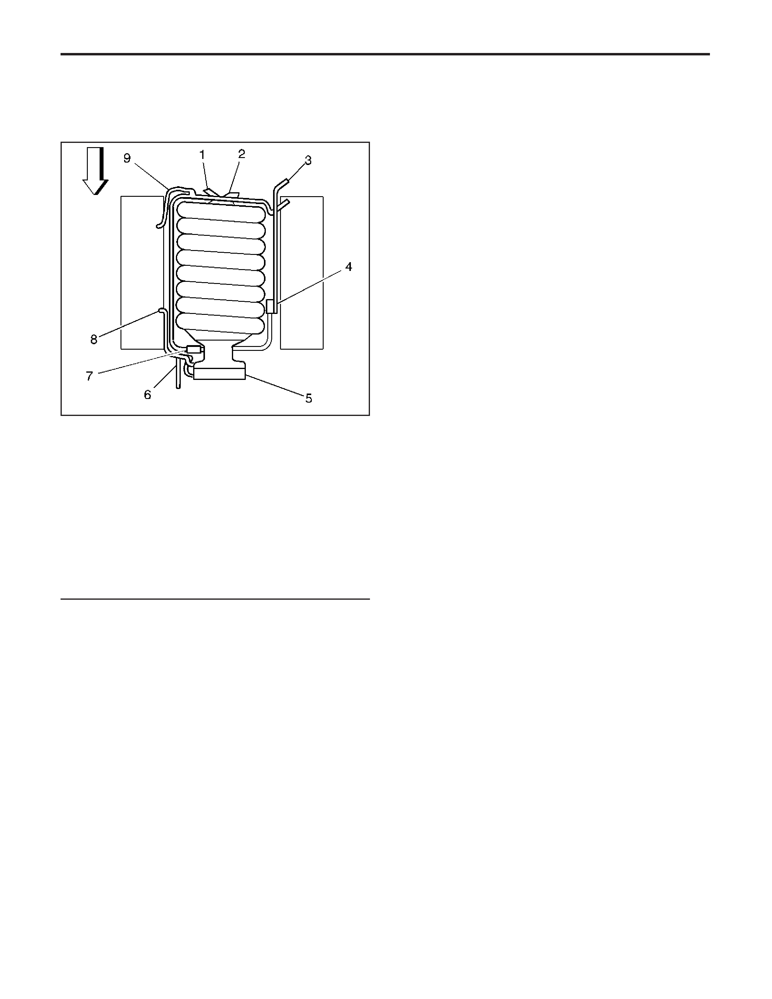
Schematic and Routing Diagrams
Emission Hose Routing Diagram
Legend
(1) To HVAC
(2) To Power Brake Vacuum Assist
(3) To EVAP Canister
(4) EVAP Canister Purge Solenoid Valve
(5) Throttle Body
(6) Engine Coolant Hoses
(7) Positive Crankcase Ventilation (PCV) Valve
(8) Crankcase Ventilation Hose
(9) Crankcase Ventilation Hose
344988
EngineEngineControls-6.0L
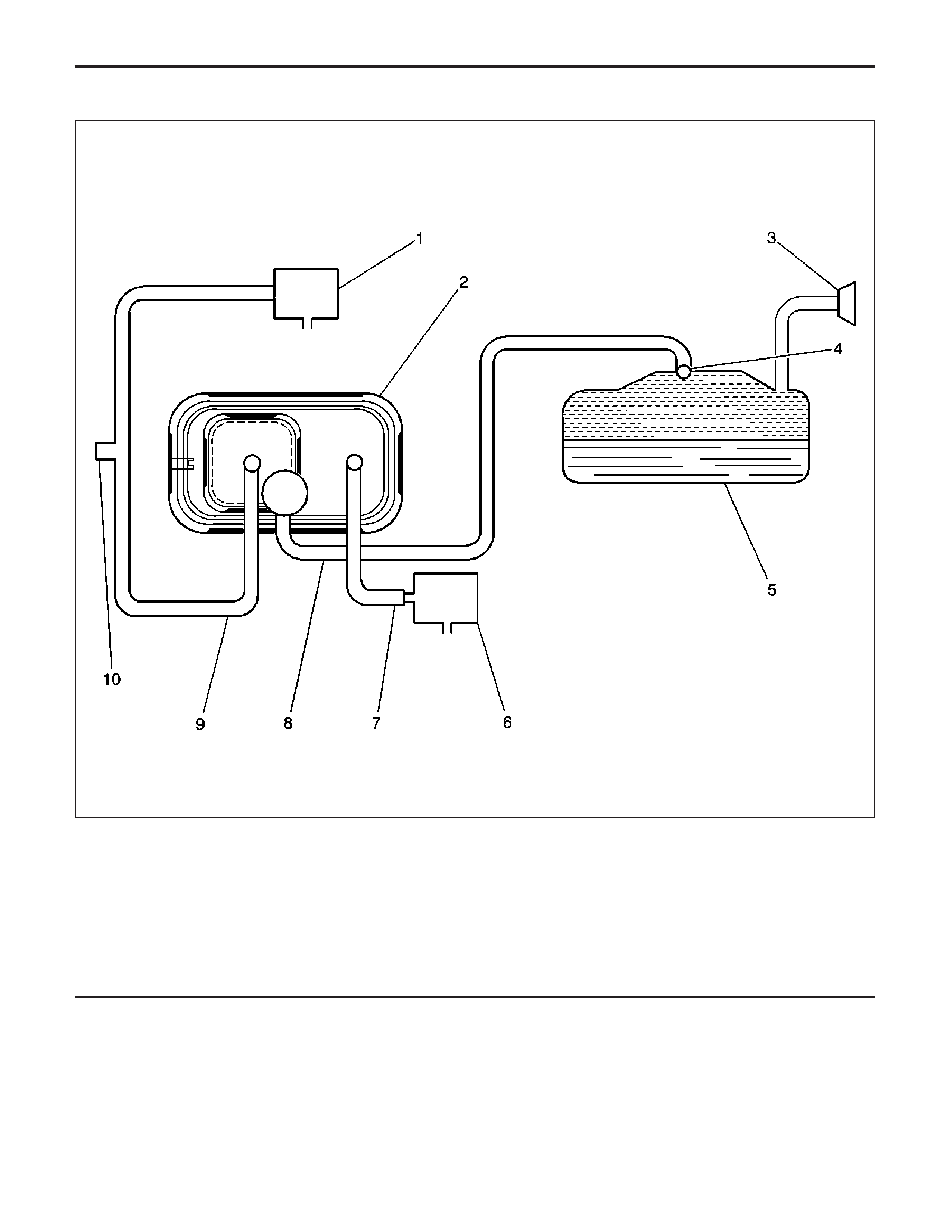
Legend
(1) EVAP Canister Purge Solenoid Valve
(2) EVAP Canister
(3) Fuel Fill Neck/Fill Cap
(4) Rollover Valve/Fuel Tank Pressure (FTP)
Sensor
(5) Fuel Tank
(6) EVAP Canister Vent Solenoid Valve
(7) Vent Hose/Pipe
(8) EVAP Vapor Pipe
(9) EVAP Purge Pipe
(10) EVAP Service Port
EvaporativeEmissions(EVAP)HoseRoutingDiagram(EVAPSystemOverview)
678941
EngineControls-6.0LEngine
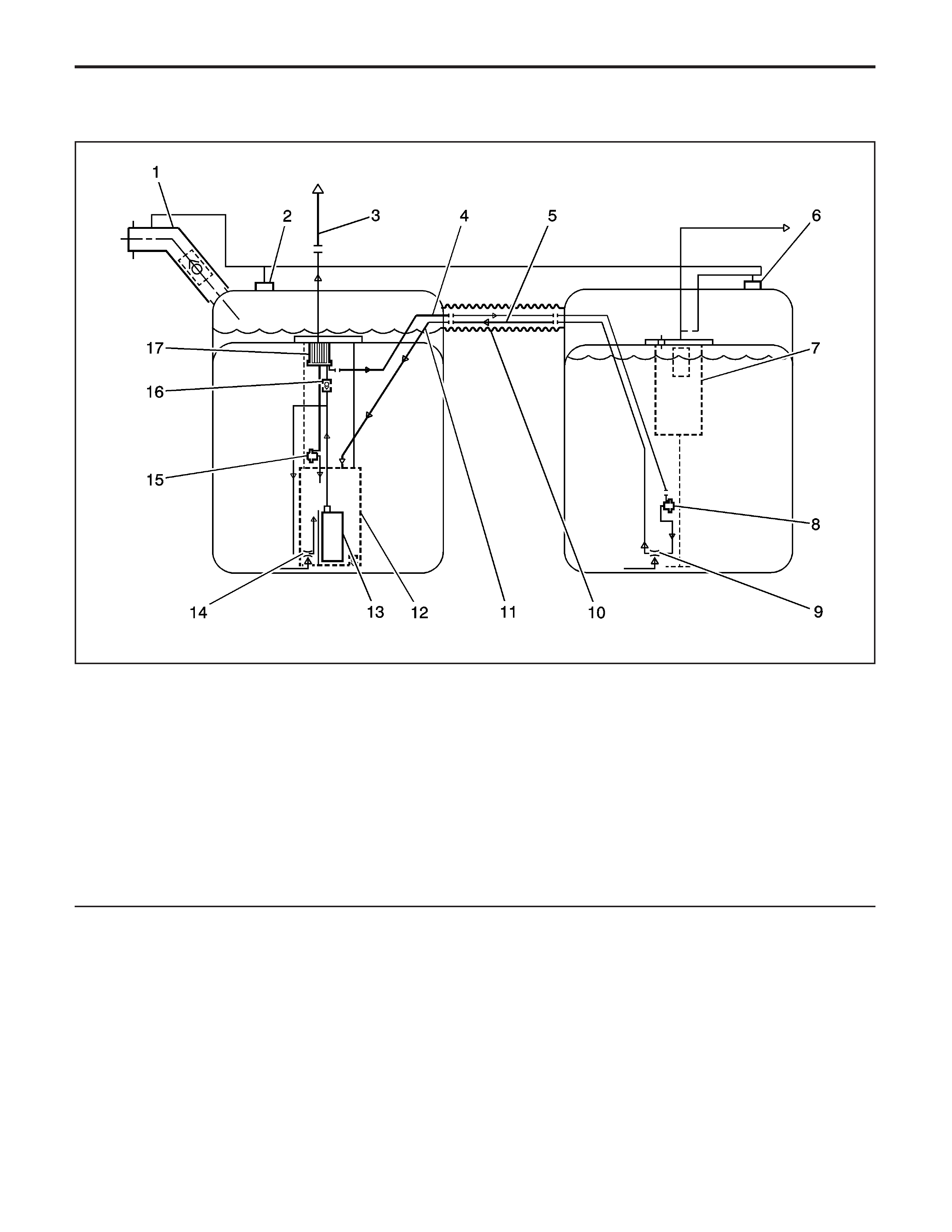
Fuel Hose/Pipes Routing Diagram
Legend
(1) Fuel Fill Hose
(2) Left Fuel Tank Grade Vent Valve
(3) Fuel Feed Pipe to Engine
(4) 5/16 Inch Auxiliary Fuel Feed Pipe
(5) 3/8 Inch Auxiliary Fuel Return Pipe
(6) Right Fuel Tank Grade Vent Valve
(7) Fill Limiter Vent Valve (FLVV)
(8) Secondary Fuel Pressure Regulator
(9) Siphon Jet Pump
(10) Convoluted Crossover Hose
(11) Anti-siphon Hole
(12) Fuel Sender Reservoir
(13) Turbine Fuel Pump
(14) Venturi Pump
(15) Primary Fuel Pressure Regulator
(16) Reverse Flow Check Valve
(17) Fuel Filter
877203
EngineEngineControls-6.0L

Diagnostic Information and Procedures
Diagnostic Starting Point - Engine
Controls
Begin the system diagnosis with
Diagnostic System
Check - Vehicle
in Vehicle DTC Information. The
Diagnostic System Check–Vehicle will provide
the following information:
• The identification of the control modules which
command the system
• The ability of the control modules to communicate
through the serial data circuit
• The identification of any stored diagnostic trouble
codes (DTCs) and the codes’ statuses
The use of the Diagnostic System Check–Vehicle will
identify the correct procedure for diagnosing the
system and where the procedure is located.
Tech 2 DataList
TheTech 2 DataListcontainsallengine
relatedparametersthatareavailableontheTech 2 .
The list is arranged in alphabetical order. A given
parameter may appear in any one of the data lists, and
in some cases may appear more than once, or in
more than one data list in order to group certain related
parameters together.
UsetheTech 2 DataListonlyafterthe
following is determined:
• The Diagnostic System Check – Vehicle is
completed.
• No diagnostic trouble codes (DTCs)
• On-board diagnostics are functioning properly.
Tech 2 valuesfromaproperlyrunningenginemay
be used for comparison with the engine you are
diagnosing.TheTech 2 DataList
represents values that would be seen on a normal
running engine.
Important:ATech 2 thatdisplaysfaultydatashould
notbeused.TheTech 2 problemshouldbe
reportedtothemanufacturer.UseofafaultyTech 2
can result in misdiagnosis and unnecessary parts
replacement.
Only the parameters listed below are referenced in
this service manual for use in diagnosis. If all values
are within the typical range described below, refer
to
Symptoms - Engine Controls
for diagnosis.
The column labeled Data List indicates where a
parametercanbelocatedontheTech 2 .Referto
theTech 2 operatingmanualfortheexactlocations
of the data lists. The following is a description of
each term listed:
All: The Parameter is in all of the data lists
indicated below.
Eng 1: Engine Data 1 List
Eng 2: Engine Data 2 List
EGR: Exhaust Gas Recirculation (EGR) Data
EE: Enhanced Evaporative Emission (EVAP) Data
FF/FR: Freeze Frame/Failure Records
FT: Fuel Trim Data List
MF: Misfire Data List
TAC: Throttle Actuator Control (TAC) Data List
CC: Cruise Control Data List
Tech 2 DataList
Tech 2 ParameterDataListParameterRange/UnitsTypicalDataValues
Engine Idling/Radiator Hose Hot/Closed Throttle/Park or Neutral/Closed Loop/Accessories Off
A/C Clutch Feedback Signal Eng 2 Yes/No No
A/C Relay Command Eng 1, 2, EGR, MF On/Off Off
A/C Compressor Cycling
Switch Eng 2 Normal/High Pressure Normal
A/C Request Signal Eng 2 Yes/No No
A/C High Pressure
Recirculation Switch Eng 2 Normal/Closed Normal
Air Fuel Ratio FF, FR Ratio 14.7:1
AIR Pump Relay Command
(w/NC1) Eng 1, FT On/Off Off
APP Average TAC 0–100% 0%
APP Indicated Angle Eng 1, Eng 2, EE, EGR,
FT, TAC 0–100% 0%
APP Sensor 1 TAC 0–5.0 Volts 0.4–0.9 Volts
EngineEngineControls-6.0L

Tech 2 DataList(cont’d)
Tech 2 ParameterDataListParameterRange/UnitsTypicalDataValues
Engine Idling/Radiator Hose Hot/Closed Throttle/Park or Neutral/Closed Loop/Accessories Off
APP Sensor 2 TAC 5.0–0 Volts 4.5–4.1 Volts
APP Sensor 3 TAC 5.0–0 Volts 4.2–3.7 Volts
APP Sensor 1 Angle TAC 0–100% 0%
APP Sensor 2 Angle TAC 0–100% 0%
APP Sensor 3 Angle TAC 0–100% 0%
APP Sensor 1 and 2
Disagree TAC Yes/No No
APP Sensor 1 and 3
Disagree TAC Yes/No No
APP Sensor 2 and 3
Disagree TAC Yes/No No
APP Sensor 1 Out of Range TAC Yes/No No
APP Sensor 2 Out of Range TAC Yes/No No
APP Sensor 3 Out of Range TAC Yes/No No
BARO Eng 1, EE, EGR, FT, FF/FR kPa/volts 65–104 kPa/3.5–4.9 Volts
Varies w/Altitude
Clutch Pedal Switch
(Manual Transmission only) Eng 1, EGR Depressed/Released Released
CMP Sensor–High to Low Eng 2 Counts Varies
CMP Sensor–Low to High Eng 2 Counts Varies
Coolant Level Switch Eng 2 OK/Low OK
Cruise Control Active Eng 1, TAC Yes/No No
Cruise Disengage 1 History CC Varies Varies
Cruise Disengage 2 History CC Varies Varies
Cruise Disengage 3 History CC Varies Varies
Cruise Disengage 4 History CC Varies Varies
Cruise Disengage 5 History CC Varies Varies
Cruise Disengage 6 History CC Varies Varies
Cruise Disengage 7 History CC Varies Varies
Cruise Disengage 8 History CC Varies Varies
Cruise Inhibit Signal
Command Eng 1 Varies Varies
Cruise On/Off Switch CC, TAC On/Off Off
Cruise Control Release Brake
Pedal Switch CC On/Off Off
Cruise Resume/Accel Switch CC, TAC Resume/Accel Resume
Cruise Set/Coast Switch CC, TAC Set/Coast Coast
Current Gear Eng 1, 2, EGR, FT, FF/FR 0–4 1
Cycles of Misfire Data MF 0–100 Counts Varies
Desired EGR Position Eng 1, EGR, MF, FF/FR 0–100% 0%
Desired EGR Position EGR 0–5 volts Less than 1.3 volts
Desired IAC Airflow Eng 1 0–64 g/s Varies
Desired IAC Position Eng 1 Counts Varies
Desired Idle Speed Eng 1, Eng 2, TAC,
EE, FF/FR RPM PCM Controlled
DTC Set This Ignition Eng 1, 2, CC, EE, FT Yes/No No
ECT Sensor Eng 1, Eng 2, EE, EGR, FT,
MF, FF/FR −39 to +140°C (−38 to
+284°F) 88–105°C (190–221°F)
EGR Learned Minimum POS EGR 0–5.0 volts Less than 1.3 volts
EngineControls-6.0LEngine

Tech 2 DataList(cont’d)
Tech 2 ParameterDataListParameterRange/UnitsTypicalDataValues
Engine Idling/Radiator Hose Hot/Closed Throttle/Park or Neutral/Closed Loop/Accessories Off
EGR Position Sensor Eng 1, EGR, FF/FR, MF 0–5.0 volts Less than 1.3 volts
Engine Load All 0–100% 1–4% Idle
7–9% 2500 RPM
Engine Oil Level Switch Eng 2 OK/Low OK
Engine Oil Life Remaining Eng 2 0–100% Varies
Engine Run Time All Hrs, Min, Sec Varies
Engine Speed All 0–10,000 RPM 500–700 RPM
EVAP Purge Solenoid
Command Eng 1, EE, FT 0–100% 10–25%
EVAP Test Result EE Test Result Varies
EVAP Test State EE Test State Varies
EVAP Vent Solenoid
Command Eng 1, EE, FT Not Venting/Venting Venting
Fail Counter FF, FR Counts Varies
Fuel Alcohol Content Eng 2 % Varies
Fuel Comp. Sensor
Frequency Eng 2 Hz Varies
Fuel Comp. Sensor On Time Eng 2 mS Varies
Fuel Level Sensor Eng 1, EE 0–5 volts 0.7–2.5 volts
Fuel Level Sensor Rear Tank Eng 1, EE 0–5 volts 0.7–2.5 volts
Fuel Tank Level Remaining EE Gallon/Liter Varies
Fuel Tank Level Remaining EE 0–100% Varies
Fuel Tank Pressure Sensor Eng 1, EE −32.7 to +14.0 mm/Hg (−17.5
to +7.5 in/H2O) Varies
Fuel Tank Pressure Sensor EE 0–5.0 volts Varies
Fuel Tank Rated Capacity EE 98 Liters (25.9 Gallons) or
128 Liters (34 Gallons) Varies with fuel tank option
Fuel Temperature Eng 2 °C/°F Varies
Fuel Trim Cell Eng 1, EE, FT 0–23 16, 17
Fuel Trim Learn Eng 1, EE, FT Enabled/Disabled Enabled, May Toggle
Generator F Terminal Signal Eng 2 Percent Varies
Generator L Terminal Signal
Command Eng 2 On/Off On
HO2S Bank 1 Sensor 1 Eng 1, EE, FT Millivolts 10–1,000 mV and Varying
HO2S Bank 1 Sensor 2 Eng 1, FT Millivolts 10–1,000 mV and Varying
HO2S Bank 2 Sensor 1 Eng 1, EE, FT Millivolts 10–1,000 mV and Varying
HO2S Bank 2 Sensor 2 Eng 1, FT Millivolts 10–1,000 mV and Varying
Fuel Level Sensor Eng 1, 2, EE 0–5 volts 0.7–2.5 volts
IAC Position Eng 1, EGR FT Counts Varies
IAT Sensor Eng 1, Eng 2, EE, EGR, FT −39 to +140°C (−38 to
+284°F) 35°C (91°F) Depends on
ambient temperature
Ignition 1 Signal Eng 1, Eng 2, CC, EE, EGR,
FT, TAC 0–25 Volts 11.5–14.5 Volts
Inj. PWM Bank 1 Average Eng 2, FT, FF/FR, MF Milliseconds 2–6
Inj. PWM Bank 2 Average Eng 2, FT, FF/FR, MF Milliseconds 2–6
Knock Retard Eng 1, EGR 0.0–16° 0°
Long Term FT Avg. Bn1 FT Percentage Near 0%
Long Term FT Avg. Bn2 FT Percentage Near 0%
Long Term FT Bank 1 Eng 1, Eng 2, EE, FT, FF/FR Percentage Near 0%
EngineEngineControls-6.0L

Tech 2 DataList(cont’d)
Tech 2 ParameterDataListParameterRange/UnitsTypicalDataValues
Engine Idling/Radiator Hose Hot/Closed Throttle/Park or Neutral/Closed Loop/Accessories Off
Long Term FT Bank 2 Eng 1, Eng 2, EE, FT, FF/FR Percentage Near 0%
Loop Status Eng 1, 2, EE, EGR,
FT, FF/FR Open/Closed Closed
Low Oil Lamp Command Eng 2 On/Off Off
MAF Sensor EGR, Eng 1, 2, FT, MF,
EE, TAC Grams Per Seconds (g/s)
1–9 g/s Idle, depends on
altitude
15–26 g/s 2,500 RPM,
depends on altitude
MAF Sensor Eng 2 0–31,999 Hz 2,000–3,000 Hz
MAP Sensor EGR, Eng 1, 2, FT, MF,
EE, TAC kPa 20–48 kPa
MAP Sensor Eng 1, Eng 2 Volts 1.0–2.0 volts
Varies with altitude
MIL Command Eng 2 Off/On Off
Mileage Since DTC Cleared Eng 2 kilometers/miles Varies
Misfire Counter Status MF Counts NormalKOEO
Misfire Current Cyl. 1–8 MF 0–200 Counts 0
Misfire History Cyl. 1–8 MF 0–65,535 Counts 0
Not Run Counter FF, FR Counts Varies
Pass Counter FF, FR Counts Varies
PCM Reset Eng 1, Eng 2, EGR, EE, FT Yes/No No
PCM/VCM in VTD Fail
Enable Eng 1 Yes/No No
Power Enrichment Eng 1 Active/Inactive Inactive
Reduced Engine Power Eng 1, EGR, TAC Yes/No No
Short Term FT Bn1 Average FT Percentage Near 0%
Short Term FT Bn2 Average FT Percentage Near 0%
Short Term FT Bank 1 Eng 1, Eng 2, EE, FT Percentage Near 0%
Short Term FT Bank 2 Eng 1, Eng 2, EE, FT Percentage Near 0%
Spark Eng 1, Eng 2, FT, MF Degrees 15°–20°
Start Up ECT Eng 2, EE, FT F°/C° Varies
Stop Lamp Pedal Switch Eng 1, 2, TAC, FF/FR Applied/Released Released
TAC/PCM Comm Signal Eng 1, TAC Yes/No Yes
TCC Enable Solenoid
Command Eng 1, Eng 2, MF On/Off Off
TCC PWM Solenoid
Command Eng 2 On/Off Off
TFP Switch Eng 2, EGR, FT Transmission Gear Position Varies
TP Desired Angle Eng 1, Eng 2, EE, EGR,
TAC, CC 0–100% 0%
TP Indicated Angle All 0–100% 0%
TP Sensor Eng 1, 2 volts 0.4–0.9 volts
TP Sensor TA, Eng 1, 2, EGR, FT,
MF, EE % Varies
TP Sensor 1 TAC 0–5.0 volts 0.4–0.9 volts
TP Sensor 2 TAC 5.0–0 volts 4.8–4.3 volts
TP Sensor 1 Angle TAC 0–100% 0%
TP Sensor 2 Angle TAC 100–0% 100%
TP Sensors Disagree TAC Yes/No No
TP Sensor 1 Out of Range TAC Yes/No No
EngineControls-6.0LEngine
2005 - Y Car GMX245 (June 22, 2004)

Tech 2 DataList(cont’d)
Tech 2 ParameterDataListParameterRange/UnitsTypicalDataValues
Engine Idling/Radiator Hose Hot/Closed Throttle/Park or Neutral/Closed Loop/Accessories Off
TP Sensor 2 Out of Range TAC Yes/No No
Torque Delivered Signal Eng 2 ft lbs/N·m 0 ft lbsKOEO
Torque Request Signal Eng 2 ft lbs/N·m 349 ft lbsKOEO
TR Sw Eng 2, EGR, FT Transmission Gear Position Varies
Vehicle Speed Sensor Eng 1, 2, FT km/h
mph 0
VTD Auto Learn Timer Eng 1 Active/Inactive Inactive
VTD Fuel Disable Eng 1 Active/Inactive Inactive
VTD Fuel Disable Until
Ign. Off Eng 1 Yes/No No
Warm-Ups w/o Emission
Faults Eng 2 0–255 Counts Varies
Warm-Ups w/o Non-Emission
Faults Eng 2 0–255 Counts Varies
Tech 2 DataDefinitions
TheEngineTech 2 DataDefinitionscontainsabrief
description of all engine related parameters available
ontheTech 2 .Thelistisinalphabeticalorder.
A given parameter may appear in any one of the data
lists. In some cases, the parameter may appear
more than once or in more than one data list in order
to group certain related parameters together.
A/C Compressor Cycling Switch: This parameter
displays the state of the air conditioning (A/C)
compressor cycling switch as determined by the
controlmodule.TheTech 2 willdisplayNormalor
Low Pressure. Normal indicates the A/C system
has enough refrigerant to close the A/C compressor
cycling switch, allowing the A/C compressor to engage.
Low Pressure indicates the A/C refrigerant system
has low pressure and the A/C compressor cycling
switch is open.
A/C Relay Command: This parameter displays the
commanded state of the air conditioning (A/C)
clutchrelaycontrolcircuit.TheTech 2 willdisplay
ON or OFF. ON indicates the A/C clutch relay
control circuit is being grounded by the control module,
allowing voltage to the A/C compressor clutch. OFF
indicates the A/C clutch relay is not being commanded
on by the control module.
A/C Request Signal: This parameter displays the
state of the air conditioning (A/C) request input to
the control module from the heating, ventilation, and
airconditioning(HVAC)controls.TheTech 2
will display Yes or No. Yes indicates the control
module is receiving a request from the HVAC system
to ground the A/C clutch relay control circuit,
engaging the A/C compressor clutch. No indicates the
control module is not receiving a request from the
HVAC system to ground the A/C clutch relay control
circuit.
Air Fuel Ratio: This parameter displays the ratio of
air to fuel as calculated by the control module
basedonvarioussensorinputs.TheTech 2 will
display a lower air fuel ratio when a richer air to fuel
mixtureiscommanded.TheTech 2 willdisplay
a higher air fuel ratio when a leaner air to fuel mixture
is commanded. In closed loop operation the air fuel
ratio should normally be around 14.2–14.7 to 1.
AIR Pump Relay Command: This parameter
displays the commanded state of the secondary air
injection(AIR)pumprelaycontrolcircuit.TheTech 2
will display ON or OFF. ON indicates the AIR pump
relay control circuit is being grounded by the
control module, allowing voltage to the AIR pump.
OFF indicates the AIR pump relay is not being
commanded on by the control module.
BARO (Gasoline): This parameter displays the
barometric pressure as calculated by the control
module using the signal from the manifold absolute
pressure (MAP) sensor measured when the ignition is
turned on with the engine not running. The control
module will update the barometric pressure during
wide-openthrottle(WOT)conditions.TheTech 2 will
display a low value when the barometric pressure is
low, and a high value when the barometric pressure
is high.
BARO (Gasoline): This parameter displays the
EngineEngineControls-6.0L

voltage signal received by the control module from the
manifold absolute pressure (MAP) sensor measured
when the ignition is turned on with the engine not
running. The control module will update the barometric
pressure during wide-open throttle (WOT) conditions.
TheTech 2 willdisplayalowvaluewhenthe
barometric pressure is low, and a high value when the
barometric pressure is high.
Clutch Pedal Switch: This parameter displays the
current state of the clutch pedal as determined by
the control module.
CMP Sensor - High To Low: This parameter
displays the number of times the signal voltage from
the camshaft position (CMP) sensor changes from high
tolow.TheTech 2 willdisplaythesetransitions
as counts.
CMP Sensor - Low To High: This parameter
displays the number of times the signal voltage from
the camshaft position (CMP) sensor changes from low
tohigh.TheTech 2 willdisplaythesetransitions
as counts.
Coolant Level Switch: This parameter displays the
level of engine coolant as determined by the control
module. The control module determines the level of the
coolant using the signal from a switch used to
monitortheenginecoolantlevel.TheTech 2 will
display low when the engine coolant level is low. The
Tech 2 willdisplayOKwhenthecoolantlevelis
correct.
Cruise Control Active: This parameter displays the
status of the cruise control system as determined
bythecontrolmodule.TheTech 2 willdisplayYes
when the cruise control system is in control of
vehiclespeed.TheTech 2 willdisplayNowhenthe
cruise control system is not operating.
Cruise Inhibit Signal Command: This parameter
displays the commanded state of the cruise inhibit
signalcircuit.TheTech 2 willdisplayOnwhenthe
control module is inhibiting cruise control operation.
TheTech 2 willdisplayOffwhenthecontrolmodule
is allowing cruise control operation.
Current Gear: This parameter displays the
transmission gear commanded by the control module.
TheTech 2 willdisplay1whenthecontrolmodule
has commanded first gear regardless of the gear
selectorposition.TheTech 2 willdisplayupto6
depending upon which gear is commanded and what
transmissionisinthevehicle.TheTech 2 will
display 9 if the transmission gear is not known.
Cycles Of Misfire Data: This parameter displays
the number of cylinder firing events that were recorded
as misfires as determined by the control module.
Desired EGR Position: This parameter displays the
position of the exhaust gas recirculation (EGR)
valvecommandedbythecontrolmodule.TheTech 2
tool will display 0 percent when the control module is
commanding the EGR valve closed.
Desired IAC Airflow: This parameter displays the
desired airflow in the idle air control (IAC) passage as
calculated by the control module.
Desired Idle Speed: This parameter displays the
engine idle speed in RPM commanded by the control
module. The control module compensates for
various engine loads in order to maintain the desired
engine RPM at idle. This parameter is not valid
unless the engine is running.
DTC Set This Ignition: This parameter displays if a
diagnostic trouble code (DTC) set during the current
ignitioncycle.TheTech 2 willdisplayYESifaDTC
is stored this ignition cycle.
ECT Sensor: This parameter displays the
temperature of the engine coolant based on a voltage
input from the engine coolant temperature (ECT)
sensortothecontrolmodule.TheTech 2 willdisplay
a low value when the coolant temperature is low,
and a high value when the coolant temperature is high.
EGR Learned Minimum Position: This parameter
displays the voltage from the EGR valve that the
control module uses to determine that the EGR valve
is closed. The voltage displayed will be the closed
position of the EGR pintle learned by the control
module.
Engine Load: This parameter displays the engine
load in percent based on inputs to the control module
fromvariousenginesensors.TheTech 2 will
display a low percentage when the engine is at idle
withlittleornoload.TheTech 2 willdisplayahigh
percentage when the engine is running at a high
RPM under a heavy load.
Engine Oil Level Switch: This parameter displays
the state of the engine oil level switch as determined
bythecontrolmodule.TheTech 2 willdisplayOKor
Low. OK indicates that the engine oil level is not too
low for safe operation of the engine. Low indicates the
engine oil level is abnormally low and has closed
the engine oil level switch.
Engine Oil Life Remaining: This parameter
displays the amount of engine oil life remaining before
requiring an oil change. This number is calculated
by the control module based on many inputs and is
displayed as a percent. The lower the percentage, the
sooner the next oil change will be required.
Engine Run Time: This parameter displays the time
elapsedsincetheenginewasstarted.TheTech 2
tool will display the time in hours, minutes and
seconds. The engine run time will reset to zero as
soon as the engine stops running.
Engine Speed: This parameter displays the speed
of the crankshaft as calculated by the control
module based on inputs from the Crankshaft
Position(CKP)Sensor.TheTech 2 willdisplaythe
engine speed in revolutions per minute (RPM).
EVAP Purge Solenoid Command: This parameter
displays the commanded state of the EVAP purge
solenoidcontrolcircuit.TheTech 2 willdisplay
0-100%. A high value indicates the purge solenoid
control circuit is being commanded more by the control
module, opening the EVAP purge solenoid. A low
value indicates the purge solenoid is being
commanded on less by the control module.
EVAPTestResult:TheTech 2 displaysNo
Result, Passed, Aborted, Fail-DTC P0440,
EngineControls-6.0LEngine

Fail-DTC P0442, Fail-DTC P0446, or Fail-DTC P1441.
TheTech 2 displaysPASSifthecontrolmodule
determines that the EVAP test has passed.
EVAPTestState:TheTech 2 displaysWaiting
For Purge, Test Running, or Test Completed.
This parameter indicates the state of the EVAP service
bay test.
EVAP Vent Solenoid Command: This parameter
displays the commanded state of the EVAP vent
solenoidcontrolcircuit.TheTech 2 willdisplay
venting or not venting. Not venting indicates the purge
solenoid control circuit is being commanded ON by
the control module, closing the EVAP vent solenoid.
Venting indicates the vent solenoid is not being
commanded by the control module, allowing the
solenoid to remain open.
FailCounter:TheTech 2 displaysthenumberof
times that a diagnostic has failed.
Fuel Alcohol Content: This parameter displays the
percentage of alcohol in the fuel. This value is
calculated by the control module using the frequency
signalfromthefuelcompositionsensor.TheTech 2
tool will display a low percentage when there is very
littlealcoholinthefuel.TheTech 2 willdisplay
a high percentage when the alcohol content of the fuel
is high.
Fuel Composition Sensor Frequency: This
parameter displays the frequency from the sensor
used to monitor the concentration of alcohol in the fuel.
The fuel composition sensor measures the fuel
capacitance, temperature, and fuel conductance to
determine the amount of alcohol contained in the fuel.
TheTech 2 willdisplayalowfrequencyreading
when the alcohol concentration of the fuel is low. The
Tech 2 willdisplayahighfrequencyreading
when the alcohol concentration of the fuel is high.
Fuel Composition Sensor On Time: This
parameter displays the pulse width signal of the fuel
composition sensor as received by the control module.
TheTech 2 willdisplayalowervalueatcolder
fueltemperatures.TheTech 2 willdisplayahigher
value at higher fuel temperatures.
Fuel Level Sensor: This parameter displays the
voltage from the signal produced by the sensor used
to monitor the fuel level inside the fuel tank. The
Tech 2 willdisplayalowvoltagereadingwhenthe
fuel level in the tank is low or near empty. The
Tech 2 willdisplayahighvoltagereadingwhenthe
fuel level in the tank is high or near full.
Fuel Level Sensor Rear Tank: This parameter
displays the voltage from the signal produced by the
sensor used to monitor the fuel level inside the
rearfueltank.TheTech 2 willdisplayalowvoltage
reading when the fuel level in the rear tank is low
ornearempty.TheTech 2 willdisplayahighvoltage
reading when the fuel level in the tank is high or
near full.
Fuel Tank Level Remaining: This parameter
displays the amount of fuel remaining in all fuel tanks
of the vehicle as measured in liters or gallons. The
control module calculates the amount of fuel remaining
in the tank by using information from the fuel level
sensors.
Fuel Tank Level Remaining: This parameter
displays the amount of fuel remaining in tall of the fuel
tanks of the vehicle as a percentage. The control
module calculates this level using the signals from the
sensors used to monitor the fuel level in the fuel
tanks.TheTech 2 willdisplayalowreadingwhen
the total fuel level in the vehicle is low or near
empty.TheTech 2 willdisplayahighreadingwhen
the fuel level in the tank is high or near full.
FuelTankRatedCapacity:TheTech 2 displays
Liters or gallons. This parameter displays the fuel
tank capacity as determined by the calibrations of the
vehicle.
Fuel Temperature: This parameter displays the
current fuel temperature as calculated by the control
module based on input from the fuel composition
sensor.TheTech 2 willdisplayahighervalueat
higherfueltemperatures.TheTech 2 willdisplaya
lower value at lower fuel temperatures.
Fuel Trim Cell: This parameter displays the fuel trim
cell as calculated by the control module based on
many sensor inputs. The fuel trim cell indicates which
cell is currently active.
FuelTrimLearn:TheTech 2 displaysEnabledor
Disabled. When conditions are appropriate for
enablinglongtermfueltrimcorrections,theTech 2
displaysEnabled.IftheTech 2 displaysDisabled,
then long term fuel trim will not respond to changes in
short term fuel trim.
Generator F-Terminal Signal: This parameter
displays the commanded state of the generator by the
control module. A High value indicates a high
charging command, and a low value indicates a low
charging command.
Generator L-Terminal Signal Command: This
parameter displays if the control module is allowing the
generatortooperate.TheTech 2 displaysONif
thegeneratorisallowedtooperate.TheTech 2
tool displays OFF if the control module is disabling the
generator.
HO2S Bank 1 Sensor 1: This parameter displays
the voltage from the signal produced by the heated
oxygen sensor used to monitor fuel trim for cylinder
bank1.TheTech 2 willdisplayalowvoltagereading
whenthatcylinderbankisrunninglean.TheTech 2
willdisplayahighvoltagereadingwhenthat
cylinder bank is running rich.
HO2S Bank 1 Sensor 2: This parameter displays
the voltage from the signal produced by the heated
oxygen sensor used to monitor catalyst efficiency for
cylinderbank1.TheTech 2 willdisplayalow
voltage reading when that cylinder bank is running
lean.TheTech 2 willdisplayahighvoltagereading
when that cylinder bank is running rich.
HO2S Bank 2 Sensor 1: This parameter displays
the voltage from the signal produced by the heated
oxygen sensor used to monitor fuel trim for cylinder
bank2.TheTech 2 willdisplayalowvoltagereading
whenthatcylinderbankisrunninglean.TheTech 2
EngineEngineControls-6.0L

willdisplayahighvoltagereadingwhenthat
cylinder bank is running rich.
HO2S Bank 2 Sensor 2: This parameter displays
the voltage from the signal produced by the heated
oxygen sensor used to catalyst efficiency for cylinder
bank2.TheTech 2 willdisplayalowvoltage
reading when that cylinder bank is running lean. The
Tech 2 willdisplayahighvoltagereadingwhen
that cylinder bank is running rich.
HO2S Heater Bn 1 Sen. 1: This parameter displays
the current through the control module when the
bank 1 sensor 1 HO2S heater is commanded ON by
the control module. HO2S Heater Bn 1 Sen. 1 is
a range of values indicating a low current when the
heater circuit resistance is high to a high current when
the heater circuit resistance is low.
HO2S Heater Bn 1 Sen. 2: This parameter displays
the current through the control module when the
bank 1 sensor 2 HO2S heater is commanded ON by
the control module. HO2S Heater Bn 1 Sen. 2 is
a range of values indicating a low current when the
heater circuit resistance is high to a high current when
the heater circuit resistance is low.
HO2S Heater Bn 2 Sen. 1: This parameter displays
the current through the control module when the
bank 2 sensor 1 HO2S heater is commanded ON by
the control module. HO2S Heater Bn 2 Sen. 1 is
a range of values indicating a low current when the
heater circuit resistance is high to a high current when
the heater circuit resistance is low.
HO2S Heater Bn 2 Sen. 2: This parameter displays
the current through the control module when the
bank 2 sensor 2 HO2S heater is commanded ON by
the control module. HO2S Heater Bn 2 Sen. 2 is
a range of values indicating a low current when the
heater circuit resistance is high to a high current when
the heater circuit resistance is low.
IAC Position: This parameter displays the position
of the Idle Air Control (IAC) motor pintle as
commandedbythecontrolmodule.TheTech 2 will
display a high count for a higher idle speed
command, and a low count for a lower idle speed
command.
IAT Sensor: This parameter displays the
temperature of the intake air calculated by the control
module based on the input from the intake air
temperature(IAT).TheTech 2 willdisplayalow
value for a low intake air temperature, and a high value
for a high intake air temperature.
Ignition 1 Signal: This parameter displays the
voltage measured at the ignition 1 circuit of the control
module. Voltage is applied to the control module
when the ignition switch is in the ignition 1 position.
TheTech 2 willdisplayahighervaluewithahigher
system voltage, and a lower value with a lower
system voltage.
InjectorPWMBank1Average:TheTech 2
displays in milliseconds. This parameter is the average
time the control module turns on each fuel injector
onthatbank.TheTech 2 willdisplayahighervalue
with a longer pulse width, or a lower value with a
shorter pulse width.
InjectorPWMBank2Average:TheTech 2
displays in milliseconds. This parameter is the average
time the control module turns on each fuel injector
onthatbank.TheTech 2 willdisplayahighervalue
with a longer pulse width, or a lower value with a
shorter pulse width.
KnockRetard:TheTech 2 displaysin°.This
parameter indicates the amount of timing retard
commandedbythecontrolmodule.TheTech 2 will
display a lower value if no knock is detected, and
a higher value as more knock is detected and
the control module retards the ignition timing.
LongTermFTAvg.Bn1:TheTech 2 displaysin
%. This parameter is the average long term fuel
trim for this bank as calculated by the control module.
TheTech 2 willdisplayofmorethan0percent
indicating that time is being added to the injector pulse
width, increasing the amount of fuel to this bank of
theengine.TheTech 2 willdisplayavalueofless
than 0 indicating time is being subtracted from the
injector pulse width, reducing the amount fuel to this
bank of the engine. A value of 0 percent indicates
no compensation is required to operate the engine at
the desired air/fuel ratio.
LongTermFTAvg.Bn2:TheTech 2 displaysin
%. This parameter is the average long term fuel
trim for this bank as calculated by the control module.
TheTech 2 willdisplayofmorethan0percent
indicating that time is being added to the injector pulse
width, increasing the amount of fuel to this bank of
theengine.TheTech 2 willdisplayavalueofless
than 0 indicating time is being subtracted from the
injector pulse width, reducing the amount fuel to this
bank of the engine. A value of 0 percent indicates
no compensation is required to operate the engine at
the desired air/fuel ratio.
LongTermFTBank1:TheTech 2 displaysin%.
This parameter is the long term fuel trim for this
bankascalculatedbythecontrolmodule.TheTech 2
willdisplayofmorethan0percentindicatingthat
time is being added to the injector pulse width,
increasing the amount of fuel to this bank of the
engine.TheTech 2 willdisplayavalueoflessthan
0 indicating time is being subtracted from the
injector pulse width, reducing the amount fuel to this
bank of the engine. A value of 0 percent indicates
no compensation is required to operate the engine at
the desired air/fuel ratio.
LongTermFTBank2:TheTech 2 displaysin%.
This parameter is the long term fuel trim for this
bankascalculatedbythecontrolmodule.TheTech 2
willdisplayofmorethan0percentindicatingthat
time is being added to the injector pulse width,
increasing the amount of fuel to this bank of the
engine.TheTech 2 willdisplayavalueoflessthan
0 indicating time is being subtracted from the
injector pulse width, reducing the amount fuel to this
bank of the engine. A value of 0 percent indicates
no compensation is required to operate the engine at
the desired air/fuel ratio.
LoopStatus:TheTech 2 displaysOpenLoopor
EngineControls-6.0LEngine

ClosedLoop.TheTech 2 displaysClosedLoopif
the control module is controlling the fuel delivery
according to the heated oxygen sensor (HO2S)
voltages.TheTech 2 displaysopenloopifthe
control module is not adjusting for HO2S inputs. In
open loop the control module bases fuel deliver
on throttle position, engine coolant temperature, and
mass airflow sensor inputs.
Low Oil Lamp Command: This parameter displays
the commanded state of the low oil lamp control
circuitbythecontrolmodule.TheTech 2 willdisplay
ON if the lamp is commanded ON by the control
module.TheTech 2 willdisplayOFFifthelampis
not being commanded by the control module.
MAFSensor:TheTech 2 displaysg/s.This
parameter indicates the airflow into the engine as
calculated by the control module based on mass
airflow(MAF)sensorinputs.TheTech 2 willdisplay
a high value at higher engine speeds, and a low
value at idle.
MAFSensor:TheTech 2 displaysinHz.This
parameter indicates the frequency signal sent from the
MAFsensortothecontrolmodule.theTech 2 will
display a high value indicates a higher engine
speed.TheTech 2 willdisplayalowvalueatidle.
MAPSensor:TheTech 2 displayskPa.This
parameter displays the pressure inside of the intake
manifold as calculated by the control module based on
theinputfromtheMAPsensor.TheTech 2 will
display a high value at cruising speed or wide open
throttle(WOT).TheTech 2 willdisplayalowvalueat
idle speed.
MAP Sensor: This parameter displays the voltage
signal from the MAP sensor to the control module. The
Tech 2 willdisplayahighvalueatcruisingspeed
orwideopenthrottle(WOT).TheTech 2 willdisplay
a low vale at idle speed.
MIL Command: This parameter displays the
commanded state of the malfunction indicator
lamp (MIL) control circuit. The malfunction indicator
lampshouldbeonwhentheTech 2 indicates
the MIL Command is On. The malfunction indicator
lampshouldbeoffwhentheTech 2 indicates
the MIL Command is Off. The control module will
command the MIL On when the ignition is ON with the
engine OFF in order to perform a bulb check.
MileageSinceDTCCleared:TheTech 2 displays
km or miles. This parameter indicates the mileage
accumulated since an emission diagnostic trouble code
cleared.
MisfireCurrentCyl.#1-8:TheTech 2 willdisplay
in counts. This parameter indicates the number of
cylinder firing events detected as possible misfires on
each cylinder during the last 200 crankshaft
revolutions as calculated by the control module. The
Tech 2 willdisplayalownumberforalownumberof
cylindermisfireevents.TheTech 2 willdisplaya
high number for a high number of cylinder misfire
events.
MisfireHistoryCyl.#1-8:TheTech 2 displaysin
counts. This parameter displays the total level of
cylinder misfires that have been calculated for each
cylinder by the control module. This parameter will not
update or show activity until a misfire DTC has
become active. The misfire history counters will update
every 200 cylinder firing events.
NotRunCounter:TheTech 2 displaysthe
number of times a DTC diagnostic has not reached
the predetermined criteria in order to run since
the first DTC run failure.
PassCounter:TheTech 2 displaysthenumber
of times a DTC has run and passed.
PCMReset:TheTech 2 displaysYesorNo.This
parameter indicates when the internal PCM resets.
TheTech 2 displaysYESwhenaninternal
PCMresetoccurred.TheTech 2 displaysNOunder
the normal operating conditions.
PCM/VCMinVTDFailEnable:TheTech 2
displaysYesorNo.TheTech 2 displaysYesifthe
body control module (BCM) and the control module
lose communications with each other after the
BCMsendsthecorrectpassword.TheTech 2
displays No if the BCM is communicating the correct
password to the PCM.
PowerEnrichment:Tech 2 displaysACTIVEor
INACTIVE. ACTIVE displayed indicates that the
control module has detected conditions appropriate to
operate in Power Enrichment mode. The control
module commands Power Enrichment mode when a
large increase in throttle position and load is detected.
While in Power Enrichment, the control module will
increase the amount of fuel delivered by entering Open
Loop and increasing the injector pulse width.
ReducedEnginePower:TheTech 2 displays
ActiveorInactive.TheTech 2 displaysActivewhen
the control module receives a signal from the
throttle actuator control (TAC) module that a TAC
systemfaultisoccurring.TheTech 2 displays
inactive when the engine is operating normally.
ShortTermFTAvg.Bn1:TheTech 2 displays
%. This parameter indicates the average short
termfueltrimforthisbank.TheTech 2 willdisplay
a value higher than 0 if the time is being added to
the injector pulse width, increasing the amount of fuel
to that bank of the engine to compensate for a
lean condition sensed by the oxygen sensors on that
bank.TheTech 2 willdisplayavaluelowerthan
0 if time is being subtracted from the injector
pulse width, reducing the amount of fuel to the engine
to compensate for a rich condition sensed by the
oxygen sensors on that bank. A value of 0 percent
indicates no compensation is required to operate
the engine at the desired air/fuel ratio.
ShortTermFTAvg.Bn2:TheTech 2 displays
%. This parameter indicates the average short
termfueltrimforthisbank.TheTech 2 willdisplay
a value higher than 0 if the time is being added to
the injector pulse width, increasing the amount of fuel
to that bank of the engine to compensate for a
lean condition sensed by the oxygen sensors on that
bank.TheTech 2 willdisplayavaluelowerthan
0 if time is being subtracted from the injector
pulse width, reducing the amount of fuel to the engine
EngineEngineControls-6.0L

to compensate for a rich condition sensed by the
oxygen sensors on that bank. A value of 0 percent
indicates no compensation is required to operate
the engine at the desired air/fuel ratio.
ShortTermFTBank1:TheTech 2 displays%.
This parameter indicates the current short term
fueltrimforthisbank.TheTech 2 willdisplaya
value higher than 0 if the time is being added to the
injector pulse width, increasing the amount of fuel
to that bank of the engine to compensate for a lean
condition sensed by the oxygen sensors on that bank.
TheTech 2 willdisplayavaluelowerthan0if
time is being subtracted from the injector pulse width,
reducing the amount of fuel to the engine to
compensate for a rich condition sensed by the oxygen
sensors on that bank. A value of 0 percent indicates
no compensation is required to operate the engine
at the desired air/fuel ratio.
ShortTermFTBank2:TheTech 2 displays%.
This parameter indicates the current short term
fueltrimforthisbank.TheTech 2 willdisplaya
value higher than 0 if the time is being added to the
injector pulse width, increasing the amount of fuel
to that bank of the engine to compensate for a lean
condition sensed by the oxygen sensors on that bank.
TheTech 2 willdisplayavaluelowerthan0if
time is being subtracted from the injector pulse width,
reducing the amount of fuel to the engine to
compensate for a rich condition sensed by the oxygen
sensors on that bank. A value of 0 percent indicates
no compensation is required to operate the engine
at the desired air/fuel ratio.
Spark: This parameter is the desired spark advance
calculated by the control module based on many
sensorinputs.TheTech 2 willdisplayalowervalue
at idle speed, and a higher value under heavy
acceleration and load conditions.
Start Up ECT: This parameter indicates the engine
coolant temperature at startup, as calculated by
the control module based on the input from the engine
coolanttemperaturesensor.TheTech 2 will
display a higher value at higher engine startup
temperatures, and a lower value at lower startup
temperatures.
Stop Lamp Pedal Switch: This parameter displays
the state of the brake pedal as determined by the
control module based on an input from the stop lamp
pedal switch. This switch turns on the stop lamps
whenthebrakepedalisdepressed.TheTech 2 will
display Applied when the brake pedal is depressed.
TCC Enable Solenoid Command: This parameter
displays the commanded state of the torque
converter clutch (TCC) solenoid control circuit. The
Tech 2 willdisplayEnabledordisabled.Enabled
indicates the TCC solenoid control circuit is being
grounded by the control module, operating the torque
converter. Disabled indicates the TCC solenoid is
not being commanded on by the control module.
TCC PWM Solenoid Command: This parameter
indicates the commanded state of the TCC PWM
Solenoidbythecontrolmodule.TheTech 2 displays
ONorOFF.TheTech 2 displaysONwhenthe
commandedstateofthesolenoidisON.TheTech 2
displays OFF when the solenoid is OFF.
TFP Switch: This parameter displays the state of
the Transmission Internal Mode Switch based on
the signal from the IMS inside the transmission. The
Tech 2 willdisplayDrive1,Drive2,Drive3,Drive4,
Park, Reverse, or Neutral. Drive 1 indicates the
Transmission Range switches C and P are closed,
connecting these circuits to ground. Drive 2 indicates
the Transmission Range switches A and C are
closed, connecting these circuits to ground. Drive
3 indicates that all of the Transmission Range switches
are closed, connecting all four circuits to ground.
Drive 4 indicates the Transmission Range switches B
and C are closed, connecting these circuits to
ground. Park indicates the Transmission Range A
switch is closed, connecting the circuit to ground.
Reverse indicates the Transmission Range switches
A, B, and P are closed, connecting these circuits
to ground. Neutral indicates the Transmission Range
switches B and P are closed, connecting these
circuits to ground.
TP Sensor: This parameter displays the voltage
signal sent to the control module from the sensor used
to monitor the position of the throttle plates. The
Tech 2 willdisplayalowvoltagewhenthethrottle
platesareatrest.TheTech 2 willdisplayahigh
voltage when the throttle plates are fully open.
TP Sensor: This parameter displays the angle of the
throttle position (TP) sensor in percent. This
information is calculated by the control module using
the signal from the throttle position sensor. The
Tech 2 willdisplayalowpercentagewhenthe
throttleplatesareclosed.TheTech 2 willdisplaya
high percentage when the throttle plates are
fully open.
TR Switch: This parameter indicates the current
state of the gear select switch on the
transmission/transaxle as calculated by the control
modulebasedontheTRswitch.TheTech 2 status
will switch from High to Low as different combinations
aremet.OntheTech 2 inPark,thePRNDL
would read P and A will be Low, and B and C will
be High.
Vehicle Speed Sensor: This parameter indicates
the vehicle speed calculated by the control module
based on an input from the vehicle speed
sensor(VSS).theTech 2 willdisplayahighvalueat
higher vehicle speeds, and a low value at lower
vehicle speeds.
VTDAutoLearnTimer:TheTech 2 displays
Active/Inactive. This parameter indicates if the control
module is ready to learn the theft deterrent password.
TheTech 2 willdisplayactiveifthesystemis
readytolearn.TheTech 2 willdisplayinactiveifthe
system has timed out or is not ready to learn the
password.
VTD Fuel Disable: This parameter Indicates if the
VTD system has received proper information to enable
ordisablefuel.TheTech 2 willdisplayActiveor
Inactive.TheTech 2 willdisplayActiveifthecontrol
module does not receive the correct password from
EngineControls-6.0LEngine

theBCM.TheTech 2 willdisplayInactiveifthe
control module receives the correct password from the
BCM. If the system is Active, the engine will not start.
VTDFuelDisableUntilIgn.Off:TheTech 2
will display Yes or No. This parameter indicates if the
VTD is disabled until the ignition is turned OFF.
TheTech 2 willdisplayYesiftheignitionisONand
atheftdeterrentDTCispresent.TheTech 2 will
display off if the system is OK and the theft deterrent
system is inactive.
Warm-upsw/oEmissionFaults:TheTech 2
displays in counts. This parameter counts the number
of warm up cycles without an emission fault present.
The parameter increments until a fault occurs. If a fault
occurs, the counter reverts to 0 until the fault is
corrected.ClearinginformationwithaTech 2 ora
loss of power to the PCM also resets the counter to 0.
Warm-upsw/oNon-EmissionFaults:TheTech 2
displaysincounts.Thisparametercounts
the number of warm up cycles without a non-emission
fault present. The parameter increments until a fault
occurs. If a fault occurs, the counter reverts to 0
until the fault is corrected. Clearing information with a
Tech 2 oralossofpowertothePCMalsoresets
the counter to 0.
Tech 2 OutputControls-EngineControls
Tech 2
Output Control Additional Menu
Selection(s) Description
Crankshaft Position
Variation Learn —
Enables the powertrain control module (PCM) to learn the variations in
the crankshaft position (CKP) system. The PCM will learn the variations
once the following conditions are met:
• Engine coolant temperature (ECT) is more than a specified value.
•AllinstructionsontheTech 2 havebeencompleted.
• The accelerator pedal is smoothly applied until the fuel cut-OFF, as
specifiedontheTech 2 ,isachieved,andthenimmediately
released.
The PCM learns the variation values on the deceleration from fuel
cut-OFF.
Cylinder Power Balance Fuel System
Enables/Disables a cylinder by turning OFF the fuel injector to the
cylinder. The fuel injector is normally enabled. The PCM disables the
fuel injector when the following conditions are met:
•AllinstructionontheTech 2 arecompleted
• Stabilized engine speed
• The fuel injector is selected
When Disable is selected the PCM turns the injector OFF for
30 seconds. During this period, the engine operates with a misfire.
Engine Speed Control TAC System
Activates the throttle activation control (TAC) system to change engine
RPM. The normal commanded state is None. To enable the RPM
control,allinstructionontheTech 2 mustbecompleted.Thesystem
will increase or decrease the RPM within a range of 350–2000 RPM.
The set step value changes the RPM by increments of 25 RPM, 100
RPM, and 500 RPM. The system remains in the commanded state until
cancelledbytheTech 2 .
EVAP Purge Solenoid Engine Output
Controls/EVAP System
Activates the evaporative emission (EVAP) purge valve. The normal
commanded state is None. The system will increase or decrease the
amount of EVAP purge valve opening by 10 percent increments within
a range of 0–100 percent. The system remains in the commanded
state until cancelled by the tool or the fuel tank pressure (FTP) exceeds
32 mm Hg (17 in H20).
EVAP Purge/Seal Engine Output
Controls/EVAP System
This control enables two functions. One function increases or
decreases the amount of purge by changing the duty cycle of the purge
valve and commanding the vent ON, non-venting. The normal
commanded state of both valves is None. The system will increase or
decrease the amount of EVAP purge valve opening by 10 percent
increments within a range of 0–100 percent. The second function seals
the system after using the purge function to obtain a specific amount of
FTP. When activated the purge valve is commanded to 0 percent and
the vent valve is commanded ON, non-venting. Both functions remain
in the commanded state until one of the following conditions occurs:
• Cancelled by the tool
• The FTP exceeds 32 mm Hg (17 in H20)
EngineEngineControls-6.0L

Tech 2 OutputControls-EngineControls(cont’d)
Tech 2
Output Control Additional Menu
Selection(s) Description
EVAP Vent Solenoid Engine Output
Controls/EVAP System
Activates the EVAP vent solenoid. The normal commanded state is
None. When commanded ON, the vent valve switches to non-venting.
The system remains in the commanded state until one of the following
conditions occurs:
• Cancelled by the tool
• Purge is greater than 0 percent, and the fuel tank pressure
exceeds 32 mm Hg (17 in H20)
Fuel Injector Balance Fuel System
Enables the fuel injector in order to verify proper fuel injector flow. The
PCM will pulse the selected injector when the following conditions
are met:
•AllinstructionontheTech 2 completed
• Fuel injector selected
• Key ON, engine OFF
The selected fuel injector can only be flowed/pulsed once per
ignition cycle.
Fuel Pump Engine Output Controls
Controls the fuel pump relay. The normal commanded state is None.
When commanded ON/OFF, the PCM turns the fuel pump ON/OFF. If
the engine is running, and the fuel pump is commanded OFF, the
engine will stall. The system remains in the commanded state until
cancelledbytheTech 2 .
Fuel Trim Enable Fuel System Disables the PCMs ability to learn new fuel trim parameters. The
system remains in the commanded state until cancelled by the
Tech 2 .
Fuel Trim Reset Fuel System Activates the reset of fuel trim data in all of the fuel trim cells.
Loop Status Engine Output Controls Controls the system loop status. The commanded states include None,
Open, or Closed. The normal commanded state is None. When
commanded Open or Closed, the system remains in the commanded
stateuntilcancelledbytheTech 2 .
Malfunction
Indicator Lamp Engine Output Controls Controls the malfunction indicator lamp (MIL). The commanded states
include None, ON, and OFF. When commanded ON or OFF, the
system remains in the commanded state until cancelled by the
Tech 2 .
MisfireGraphic—Graphstheaccumulatedmisfiresoccurringineachcylinder.TheTech 2
allowsforaresetofthemisfiregraph.
O2S Heater Control Engine Output Controls
Activates the HO2S Heater. The commanded states include None,
ON, and OFF. The normal commanded state is None. On a cold
engine, with the key ON, engine OFF, the HO2S signal will continue to
drop below bias when commanded ON. The system remains in the
commanded state until cancelled by the tool.
EngineControls-6.0LEngine

DTC P0016
Circuit Description
The engine control module (ECM) uses the crankshaft
position (CKP) sensor and the camshaft
position (CMP) sensor signals to monitor the
correlation between the crankshaft and camshaft
positions. If the ECM detects that the timing between
the crankshaft and the camshaft is incorrect,
DTC P0016 sets.
DTC Descriptor
This diagnostic procedure supports the following DTC:
DTC P0016 Crankshaft Position (CKP) Camshaft
Position (CMP) Correlation
Conditions for Running the DTC
• The engine is cranking, or the engine is running.
• DTCs P0335, P0336, P0340, P0341 are
not set.
• DTC P0016 runs continuously when the above
conditions are met.
Conditions for Setting the DTC
The ECM detects that the timing between the
crankshaft and the camshaft is incorrect for one cam
trigger pulse.
Action Taken When the DTC Sets
• The control module illuminates the malfunction
indicator lamp (MIL) when the diagnostic runs
and fails.
• The control module records the operating
conditions at the time the diagnostic fails. The
control module stores the information in the
Freeze Frame/Failure Records.
Conditions for Clearing the MIL/DTC
• The control module turns OFF the MIL after
3 consecutive ignition cycles that the diagnostic
runs and does not fail.
• A current DTC last test failed clears when the
diagnostic runs and passes.
• A history DTC clears after 40 consecutive warm-up
cycles if no failures are reported by this or any
other emission related diagnostic.
Test Description
The number below refers to the step number on the
diagnostic table.
5. An incorrectly installed camshaft gear, crankshaft
sprocket, or timing chain can cause this DTC
to set.
DTC P0016
Step Action Yes No
Schematic Reference:
Engine Controls Schematics
Connector End View Reference:
Engine Control Module (ECM) Connector End Views
or
Engine Controls Connector
End Views
1Did you perform the Diagnostic System Check – Vehicle?
Go to
Step 2
Go to
Diagnostic
System Check -
Vehicle
in Vehicle
DTC Information
2
1. Start the engine.
2. Allow the engine to reach normal operating temperature.
3.ObservetheDTCinformationwithaTech 2 .
DoestheTech 2 displayDTCP0016failedthisignition?Goto
Step4
Goto
Step3
3
1. Observe the Freeze Frame/Failure Records for this DTC.
2. Turn OFF the ignition for 30 seconds.
3. Start the engine.
4. Operate the vehicle within the Conditions for Running the
DTC. You may also operate the vehicle within the conditions
that you observed from the Freeze Frame/Failure Records.
Did the DTC fail this ignition? Go to
Step 4
Go to
Intermittent
Conditions
4
ObservetheDTCinformationwithaTech 2 .
DoestheTech 2 displaythatDTCP0335,P0336,P0340,or
P0341 also failed this ignition?
Go to
Diagnostic
Trouble Code (DTC)
List - Vehicle
in
Vehicle
DTC Information Go to
Step 5
EngineEngineControls-

DTC P0016 (cont’d)
Step Action Yes No
5
Repair one of the following conditions:
• The camshaft gear and the crankshaft sprocket alignment
marks are not aligned properly
• A timing chain tensioner condition
• An incorrectly installed timing chain
• Excessive play in the timing chain
• Incorrect indexing of the timing mark on either the crankshaft
sprocket or the camshaft gear
Refer to
Timing Chain and Sprockets Cleaning and Inspection
,
Camshaft and Bearings Cleaning and Inspection
, and
Timing
Chain and Sprockets Installation
in Engine Mechanical.
Did you complete the repair? Go to
Step 6
—
6
1.CleartheDTCswithaTech 2 .
2. Turn OFF the ignition for 30 seconds.
3. Start the engine.
4. Operate the vehicle within the Conditions for Running the
DTC. You may also operate the vehicle within the conditions
that you observed from the Freeze Frame/Failure Records.
Did the DTC fail this ignition? Go to
Step 2
Go to
Step 7
7
ObservetheCaptureInfowithaTech 2
Are there any DTCs that have not been diagnosed? Go to
Diagnostic
Trouble Code (DTC)
List - Vehicle
in
Vehicle
DTC Information System OK
EngineControls-6.0LEngine

DTC P0030, P0036, P0050, or P0056
Circuit Description
Heated oxygen sensors (HO2S) are used for fuel
control and post catalyst monitoring. Each HO2S
compares the oxygen content of the surrounding air
with the oxygen content in the exhaust stream.
The HO2S must reach operating temperature to
provide an accurate voltage signal. A heating element
inside the HO2S minimizes the time required for
the sensor to reach operating temperature. Voltage is
provided to the heater by the ignition 1 voltage
circuit through a fuse. With the engine running, ground
is provided to the heater by the HO2S heater low
control circuit, through a low side driver within
the engine control module (ECM).
The ECM commands the heater ON or OFF to
maintain a specific HO2S operating temperature range.
The ECM monitors the voltage on the HO2S heater
low control circuit for heater fault diagnosis. If the ECM
detects that the HO2S heater low control circuit
voltage is not within a specified range, DTC P0030
sets for HO2S bank 1 sensor 1, DTC P0036 sets
for HO2S bank 1 sensor 2, DTC P0050 sets for HO2S
bank 2 sensor 1, DTC P0056 sets for HO2S bank 2
sensor 2.
DTC Descriptors
This diagnostic procedure supports the
following DTCs:
• DTC P0030 HO2S Heater Control Circuit Bank 1
Sensor 1
• DTC P0036 HO2S Heater Control Circuit Bank 1
Sensor 2
• DTC P0050 HO2S Heater Control Circuit Bank 2
Sensor 1
• DTC P0056 HO2S Heater Control Circuit Bank 2
Sensor 2
Conditions for Running the DTC
• The Ignition 1 Signal parameter is between 11–
18 volts.
• The engine speed is more than 425 RPM.
• This diagnostic runs continuously once the above
conditions are met.
Conditions for Setting the DTC
The ECM detects that the affected HO2S heater low
control circuit is not within a specified range for
25 seconds.
Action Taken When the DTC Sets
• The control module illuminates the malfunction
indicator lamp (MIL) on the second consecutive
ignition cycle that the diagnostic runs and fails.
• The control module records the operating
conditions at the time the diagnostic fails. The
first time the diagnostic fails, the control module
stores this information in the Failure Records.
If the diagnostic reports a failure on the
second consecutive ignition cycle, the control
module records the operating conditions at
the time of the failure. The control module writes
the operating conditions to the Freeze Frame
and updates the Failure Records.
Conditions for Clearing the MIL/DTC
• The control module turns OFF the malfunction
indicator lamp (MIL) after 3 consecutive ignition
cycles that the diagnostic runs and does not fail.
• A current DTC, Last Test Failed, clears when the
diagnostic runs and passes.
• A history DTC clears after 40 consecutive warm-up
cycles, if no failures are reported by this or any
other emission related diagnostic.
•CleartheMILandtheDTCwithaTech 2 .
DTC P0030, P0036, P0050, or P0056
Step Action Values Yes No
Schematic Reference:
Engine Controls Schematics
Connector End View Reference:
Engine Control Module (ECM) Connector End Views
or
Engine Controls Connector
End Views
1
Did you perform the Diagnostic System Check – Vehicle?
—
Go to
Step 2
Go to
Diagnostic
System Check -
Vehicle
in
Vehicle
DTC Information
2 Is DTC P0030 or P0050 set? — Go to
Step 4
Go to
Step 3
EngineEngineControls-6.0L

DTC P0030, P0036, P0050, or P0056 (cont’d)
Step Action Values Yes No
3
1. Start the engine.
2. Wait 1 minute to allow the heated oxygen sensor
(HO2S) heater current to stabilize.
3. Observe the affected HO2S heater current parameter
withaTech 2
Is the HO2S heater current parameter within the
specified range?
0.25–1.375 A
Go to
Step 5
Go to
Step 6
4
1. Start the engine.
2. Wait 1 minute to allow the HO2S heater current to
stabilize.
3. Observe the affected HO2S heater current parameter
withaTech 2 .
Is the HO2S heater current parameter within the
specified range?
0.25–3.125 A
Go to
Step 5
Go to
Step 6
5
1. Observe the Freeze Frame/Failure Records for
this DTC.
2. Turn OFF the ignition for 30 seconds.
3. Start the engine.
4. Operate the vehicle within the Conditions for Running
the DTC. You may also operate the vehicle within the
conditions that you observed from the Freeze
Frame/Failure Records.
Did the DTC fail this ignition?
—
Go to
Step 6
Go to
Intermittent
Conditions
6
1. Turn OFF the ignition.
2. Inspect the fuse that supplies the applicable HO2S
heater.
Is the fuse open?
—
Go to
Step 7
Go to
Step 8
7
Test the ignition 1 voltage circuit for a short to ground.
Refer to
Circuit Testing
,
Wiring Repairs
, and
Heated
Oxygen Sensor (HO2S) Wiring Repairs
in Wiring Systems.
Did you find and correct the condition?
—
Go to
Step 20
Go to
Step 10
8
1. Disconnect the affected HO2S.
2. Turn ON the ignition, with the engine OFF.
3. Probe the ignition 1 voltage circuit of the HO2S
harness connector on the engine harness side with a
test lamp that is connected to a good ground. Refer to
Probing Electrical Connectors
in Wiring Systems.
Does the test lamp illuminate?
—
Go to
Step 9
Go to
Step 17
9
1. Turn OFF the ignition.
2. Probe the HO2S heater low control circuit of the
HO2S harness connector on the engine harness side
with a test lamp connected to battery voltage.
3. With the ignition still OFF, observe the test lamp.
Does the test lamp illuminate?
—
Go to
Step 12
Go to
Step 11
10
Test the ignition 1 voltage circuit on the sensor side of the
HO2S 1 connector for a short to ground. Refer to
Circuit
Testing
in Wiring Systems.
Is the sensor shorted to ground?
—
Go to
Step 18
Go to
Intermittent
Conditions
11 Start the engine with the test lamp still connected from the
previous step.
Is the test lamp ON steady or blinking? —Go to
Step 15
Go to
Step 13
12
Test the HO2S heater low control circuit for a short to
ground. Refer to
Circuit Testing
,
Wiring Repairs
, and
Heated Oxygen Sensor (HO2S) Wiring Repairs
in Wiring
Systems.
Did you find and correct the condition?
—
Go to
Step 20
Go to
Step 16
EngineControls-6.0LEngine

DTC P0030, P0036, P0050, or P0056 (cont’d)
Step Action Values Yes No
13
Test the HO2S heater low control circuit for a short to
voltage. Refer to
Circuit Testing
,
Wiring Repairs
, and
Heated Oxygen Sensor (HO2S) Wiring Repairs
in Wiring
Systems.
Did you find and correct the condition?
—
Go to
Step 20
Go to
Step 14
14
Test the HO2S heater low control circuit for an open or for
high resistance. Refer to
Circuit Testing
,
Wiring Repairs
,
and
Heated Oxygen Sensor (HO2S) Wiring Repairs
in
Wiring Systems.
Did you find and correct the condition?
—
Go to
Step 20
Go to
Step 16
15
Test for shorted terminals and for poor connections at the
HO2S. Refer to
Testing for Intermittent Conditions and
Poor Connections
,
Connector Repairs
, and
Heated Oxygen
Sensor (HO2S) Wiring Repairs
in Wiring Systems.
Did you find and correct the condition?
—
Go to
Step 20
Go to
Step 18
16
Test for shorted terminals and for poor connections at the
engine control module (ECM). Refer to
Testing for
Intermittent Conditions and Poor Connections
,
Connector
Repairs
,
Heated Oxygen Sensor (HO2S) Wiring Repairs
in
Wiring Systems.
Did you find and correct the condition?
—
Go to
Step 20
Go to
Step 19
17
Repair the open or high resistance in the ignition 1 voltage
circuit. Refer to
Wiring Repairs
and
Heated Oxygen Sensor
(HO2S) Wiring Repairs
in Wiring Systems.
Did you complete the repair?
—
Go to
Step 20
—
18
Replace the affected HO2S. Refer to
Heated Oxygen
Sensor (HO2S) Replacement Bank 1 Sensor 1
,
Heated
Oxygen Sensor (HO2S) Replacement Bank 1 Sensor 2
,
Heated Oxygen Sensor (HO2S) Replacement Bank 2
Sensor 1
,or
Heated Oxygen Sensor (HO2S) Replacement
Bank 2 Sensor 2
.
Did you complete the replacement?
—
Go to
Step 20
—
19
Replace the ECM. Refer to
Control Module References
in
Computer/Integrating Systems for replacement, setup, and
programming.
Did you complete the replacement?
—
Go to
Step 20
—
20
1. Replace the fuse, if necessary.
2.CleartheDTCswithaTech 2 .
3. Turn OFF the ignition for 30 seconds.
4. Start the engine.
5. Operate the vehicle within the Conditions for Running
the DTC. You may also operate the vehicle within the
conditions that you observed from the Freeze
Frame/Failure Records.
Did the DTC fail this ignition?
—
Go to
Step 2
Go to
Step 21
21
ObservetheCaptureInfowithaTech 2 .
Are there any DTCs that have not been diagnosed? —
Go to
Diagnostic
Trouble
Code (DTC) List -
Vehicle
in Vehicle
DTC Information System OK
EngineEngineControls-6.0L

DTC P0068
Circuit Description
The throttle position (TP) is compared to an expected
throttle position based on engine load. The engine
control module (ECM) determines engine load based
on inputs from the mass air flow (MAF) and the
manifold absolute pressure (MAP) sensors. If the ECM
detects that the current load and throttle position
are not consistent with the expected load and throttle
position, DTC P0068 is set.
DTC Descriptor
This diagnostic procedure supports the following DTC:
DTC P0068 Throttle Body Airflow Performance
Conditions for Running the DTC
• DTCs P0101, P0102, P0103, P0106, P0107,
P0108, P0120, P0121, P0122, P0123, P0220,
P0221, P0222, P0223, P0601, P0602, P0603,
P0604, P0606, P0607, P1516, P2101 are not set.
• The engine speed is more than 600 RPM and less
than 6,300 RPM.
• DTC P0068 runs continuously when the above
conditions are met.
Conditions for Setting the DTC
The ECM detects that the throttle position and the
indicated engine load do not correspond with the
expected load and throttle position for less than
1 second.
Action Taken When the DTC Sets
• The control module illuminates the malfunction
indicator lamp (MIL) when the diagnostic runs
and fails.
• The control module records the operating
conditions at the time the diagnostic fails. The
control module stores this information in the
Freeze Frame and/or the Failure Records.
• The control module commands the TAC system to
operate in the Reduced Engine Power mode.
• A message center or an indicator displays
Reduced Engine Power.
• Under certain conditions the control module
commands the engine OFF.
Conditions for Clearing the MIL/DTC
• The control module turns OFF the malfunction
indicator lamp (MIL) after 3 consecutive ignition
cycles that the diagnostic runs and does not fail.
• A current DTC, Last Test Failed, clears when the
diagnostic runs and passes.
• A history DTC clears after 40 consecutive warm-up
cycles, if no failures are reported by this or any
other emission related diagnostic.
•CleartheMILandtheDTCwithaTech 2 .
DTC P0068
Step Action Value(s) Yes No
Schematic Reference:
Engine Controls Schematics
Connector End View Reference:
Engine Control Module (ECM) Connector End Views
or
Engine Controls Connector
End Views
1
Did you perform the Diagnostic System Check – Vehicle?
—
Go to
Step 2
Go to
Diagnostic
System Check -
Vehicle
in
Vehicle
DTC Information
2
Are DTCs P0101, P0102, P0103, P0106, P0107, P0108,
P0120, P0121, P0122, P0123, P0220, P0222, P0223,
P1516, P2101, P2119, P2176 also set? —
Go to
Diagnostic
Trouble
Code (DTC) List -
Vehicle
in Vehicle
DTC Information Go to
Step 3
3
1. Observe the Freeze Frame/Failure Records for
this DTC.
2. Turn OFF the ignition.
3. Start the engine.
4. Operate the vehicle within the Conditions for Running
the DTC. You may also operate the vehicle within the
conditions that you observed from the Freeze
Frame/Failure Records.
Did the DTC fail this ignition?
—
Go to
Step 4
Go to
Intermittent
Conditions
EngineControls-6.0LEngine

DTC P0068 (cont’d)
Step Action Value(s) Yes No
4
Inspect for the following conditions:
• Vacuum hoses for splits, kinks, and proper connections
as shown on Vehicle Emission Control
Information label
• Any type of leak or restriction
• Air leaks at the throttle body mounting area and the
intake manifold sealing surfaces
• Restrictions in the air intake system, including filter
Did you find and correct the condition?
—
Go to
Step 12
Go to
Step 5
5
Important: Observe the throttle position (TP) sensors 1
and2angleparameterwithaTech 2 .
1. Start the engine.
2. Apply accelerator pedal slightly and record TP 1 and 2
angles.
3. Turn OFF the ignition.
Is the difference between TP sensor 1 angle and TP
sensor 2 angle less than the specified value?
3%
Go to
Step 10
Go to
Step 6
6
Test the TP sensor 1 5-volt reference circuit for high
resistance. Refer to
Circuit Testing
and
Wiring Repairs
in
Wiring Systems.
Did you find and correct the condition?
—
Go to
Step 12
Go to
Step 7
7
Test the TP sensor low reference circuit for high
resistance. Refer to
Circuit Testing
and
Wiring Repairs
in
Wiring Systems.
Did you find and correct the condition?
—
Go to
Step 12
Go to
Step 8
8
Test the TP sensor 1 signal circuit for high resistance.
Refer to
Circuit Testing
and
Wiring Repairs
in Wiring
Systems.
Did you find and correct the condition?
—
Go to
Step 12
Go to
Step 9
9
Test the TP sensor 2 signal circuit for high resistance.
Refer to
Circuit Testing
and
Wiring Repairs
in Wiring
Systems.
Did you find and correct the condition?
—
Go to
Step 12
Go to
Step 10
10
Inspect the throttle body for the following conditions:
• A loose or damaged throttle blade
• A broken throttle shaft
Did you find a condition?
—
Go to
Step 11
—
11 Replace the throttle body assembly. Refer to
Throttle Body
Installation
.
Did you complete the replacement? —Go to
Step 12
—
12
1.CleartheDTCswithaTech 2 .
2. Turn OFF the ignition for 30 seconds.
3. Start the engine.
4. Operate the vehicle within the Conditions for Running
the DTC. You may also operate the vehicle within the
conditions that you observed from the Freeze
Frame/Failure Records.
Did the DTC fail this ignition?
—
Go to
Step 3
Go to
Step 13
13
Important: More than one throttle actuator control (TAC)
system-related DTC may set. This is due to the many
redundant tests run continuously on this system. Locating
and repairing one individual condition may correct more
than one DTC. Be aware of this when reviewing
Captured Info.
ObservetheCaptureInfowithaTech 2 .
Are there any DTCs that have not been diagnosed?
—Go to
Diagnostic
Trouble
Code (DTC) List -
Vehicle
in Vehicle
DTC Information System OK
EngineEngineControls-6.0L

DTC P0101
Circuit Description
The mass air flow (MAF) sensor is an air flow meter
that measures the amount of air entering the
engine. The engine control module (ECM) uses the
MAF sensor signal to provide the correct fuel delivery
for all engine speeds and loads. A small quantity
of air entering the engine indicates a deceleration or
idle condition. A large quantity of air entering the
engine indicates an acceleration or high load condition.
The MAF sensor has the following circuits:
• An ignition 1 voltage circuit
• A ground circuit
• A signal circuit
The ECM applies a voltage to the sensor on the signal
circuit. The sensor uses the voltage to produce a
frequency based on the inlet air flow through
the sensor bore. The frequency varies within a range
of near 2,000 Hertz at idle to near 11,500 Hertz at
maximum engine load. The ECM uses the following
sensor inputs to calculate a predicted MAF value:
• The manifold absolute pressure (MAP) estimated
• The intake air temperature (IAT) sensor
• The throttle areas from the engine temperature
control (ETC) and intake air temperature (IAT),
barometric pressure (BARO), and the
estimated MAP
The ECM compares the actual MAF sensor frequency
signal to the predicted MAF value. This comparison
will determine if the signal is stuck too low or too high
for a given operating condition. If the ECM detects
the actual MAF sensor frequency signal is to high of a
delta from the calculated MAF value and a manifold
absolute pressure (MAP) modeled signal is to high of a
delta from measured MAP the DTC P0101 sets.
DTC Descriptor
This diagnostic procedure supports the following DTC:
DTC P0101 Mass Air Flow (MAF) Sensor Performance
Conditions for Running the DTC
• DTCs P0102, P0103, P0106, P0107, P0108,
P0112, P0113, P0116, P0117, P0118, P0120,
P0128, P0220, P0315, P0335, P0442, P0446,
P0449, P0455, P0496 and P2135 are not set.
• The engine coolant temperature (ECT) is
between 70°C (158°F) and −7°C (19.4°F).
• The engine RPM is between 555 and 6400.
• DTC P0101 runs continuously when the above
conditions are met.
Conditions for Setting the DTC
The ECM detects that the actual MAF sensor
frequency signal is not within a predetermined range
of the calculated MAF value for more than 4 seconds.
Action Taken When the DTC Sets
• The control module illuminates the malfunction
indicator lamp (MIL) on the second consecutive
ignition cycle that the diagnostic runs and fails.
• The control module records the operating
conditions at the time the diagnostic fails. The
first time the diagnostic fails, the control module
stores this information in the Failure Records.
If the diagnostic reports a failure on the
second consecutive ignition cycle, the control
module records the operating conditions at
the time of the failure. The control module writes
the operating conditions to the Freeze Frame
and updates the Failure Records.
Conditions for Clearing the MIL/DTC
• The control module turns OFF the malfunction
indicator lamp (MIL) after 3 consecutive ignition
cycles that the diagnostic runs and does not fail.
• A current DTC, Last Test Failed, clears when the
diagnostic runs and passes.
• A history DTC clears after 40 consecutive warm-up
cycles, if no failures are reported by this or any
other emission related diagnostic.
•CleartheMILandtheDTCwithaTech 2 .
Diagnostic Aids
• Inspect the harness of the mass air flow (MAF)
sensor to verify that it is not routed too close
to the following components:
− The secondary ignition wires or coils
− Any solenoids
− Any relays
− Any motors
• A low minimum air rate through the sensor bore at
idle or during deceleration may cause this DTC to
set. Inspect for the following conditions:
− Any deposits on the throttle plate or in the
throttle bore
− Any vacuum leak downstream of the MAF
sensor
• Inspect for any contamination or debris on the
sensing elements of the MAF sensor.
• Inspect the air induction system for any water
intrusion. Any water that reaches the MAF sensor
will skew the sensor and may cause this DTC
to set.
• A wide open throttle acceleration from a stop
should cause the MAF sensor parameter on
theTech 2 toincreaserapidly.Thisincrease
should be from 5–12 g/s at idle to 200 g/s or more
at the time of the 1–2 shift. If the increase is not
observed, inspect for a restriction in the induction
system or the exhaust system.
• Inspect for a skewed or stuck ECT sensor.
EngineControls-6.0LEngine

• A high resistance of 15 ohms or more on the
ignition 1 voltage circuit may cause the DTC to set.
A high resistance may cause a driveability
concern before this DTC sets.
• The barometric pressure that is used to calculate
the predicted mass air flow value is initially
based on the manifold absolute pressure (MAP)
sensor at key ON. When the engine is running the
BARO value is continually updated near wide
open throttle. A skewed MAP sensor will cause the
calculated mass air flow value to be inaccurate
and may result in a no start condition. The value
shown for the MAP sensor parameter varies
with the altitude. With the ignition ON and
the engine OFF, 101 kPa is the approximate value
near sea level. This value will decrease by
approximately 3 kPa for every 305 meters
(1,000 feet) of altitude.
• A high resistance on the low reference circuit of
the MAP sensor may cause this DTC to set.
• A short to voltage on the 5-volt reference circuit of
the MAP sensor may cause this DTC to set.
If the condition is intermittent, refer to
Intermittent
Conditions
.
Test Description
The numbers below refer to the step numbers on the
diagnostic table.
5. This step will determine if the manifold absolute
pressure (MAP) sensor pressure is within the
proper range for a given altitude.
6. This step will determine if the MAP sensor voltage
is within the proper range at idle.
7. This step will determine if the MAP sensor
responds properly to the change in manifold
pressure.
8. This step will determine if the throttle position (TP)
sensors are operating properly.
9. This step will determine if any mechanical faults
have caused this DTC to set.
10. This voltage drop will determine if high resistance
has caused this DTC to set.
DTC P0101
Step Action Values Yes No
Schematic Reference:
Engine Controls Schematics
Connector End View Reference:
Engine Control Module (ECM) Connector End Views
or
Engine Controls Connector
End Views
1
Did you perform the Diagnostic System Check – Vehicle?
—
Go to
Step 2
Go to
Diagnostic
System Check -
Vehicle
in
Vehicle
DTC Information
2Attempt to start the engine.
Does the engine start? —Go to
Step 3
Go to
Step 5
3
Observe the Diagnostic Trouble Code (DTC) Information
withtheTech 2 .
DoestheTech 2 displayanyDTCssetotherthan
DTC P0068 or DTC P0101? —
Go to
Diagnostic
Trouble
Code (DTC) List -
Vehicle
in Vehicle
DTC Information Go to
Step 4
4
1. Observe the Freeze Frame/Failure Records for
this DTC.
2. Turn OFF the ignition for 30 seconds.
3. Start the engine.
4. Operate the vehicle within the Conditions for Running
the DTC. You may also operate the vehicle within the
conditions that you observed from the Freeze
Frame/Failure Records.
Did the DTC fail this ignition?
—
Go to
Step 5
Go to
Diagnostic Aids
EngineEngineControls-6.0L

DTC P0101 (cont’d)
Step Action Values Yes No
5
Important: The Altitude vs. Barometric Pressure table
indicates a pressure range for a given altitude under
normal weather conditions. Weather conditions consisting
of very low or very high pressure and/or temperature may
cause a reading to be slightly out of range.
1. Turn ON the ignition, with the engine OFF.
2. Observe the manifold absolute pressure (MAP) sensor
kPaparameterwithaTech 2 .
3. The MAP sensor pressure should be within the
specified range for your altitude. Refer to
Altitude vs
Barometric Pressure
.
Is the MAP sensor pressure within the specified range, as
indicated on the altitude vs. barometric pressure table?
—
Go to
Step 6
Go to
DTC P0106
6
1. Start the engine.
2. Turn OFF all accessories.
3. Allow the engine to reach operating temperature.
4. Observe the manifold absolute pressure (MAP) sensor
parameterwithaTech 2 .
Is the MAP sensor parameter within the specified range?
0.8–2.0 V
Go to
Step 7
Go to
DTC P0106
7
1. Idle the engine.
2. Observe the manifold absolute pressure (MAP) sensor
parameterwithaTech 2 .
3. Increase the engine speed slowly to 3,000 RPM and
then back to idle.
Does the MAP sensor parameter change smoothly and
gradually through the specified range of the test?
—
Go to
Step 8
Go to
DTC P0106
8
1. Turn OFF the ignition for 30 seconds.
2. Turn ON the ignition with the engine OFF.
3. Observe the throttle position (TP) indicated angle
parameterwithaTech 2 .
4. Depress the accelerator pedal completely.
Is the TP indicated angle parameter within the
specified range?
95–100%
Go to
Step 9
Go to
DTC P0120
9
1. Turn OFF the ignition.
2. Inspect for the following conditions:
• An improperly routed mass air flow (MAF) sensor
harness
• A restricted or collapsed air intake duct
• A misaligned air intake duct
• A dirty or deteriorating air filter element
• Any objects blocking the air inlet screen of the
MAF sensor, if equipped
• Any contamination or debris on the sensing
elements of the MAF sensor
• Any water intrusion in the induction system
• Any vacuum leak downstream of the MAF sensor
• A skewed or stuck engine coolant
temperature (ECT) sensor
• Any type of restriction in the exhaust system—
Refer to
Restricted Exhaust
in Engine Exhaust.
Did you find and correct the condition?
—
Go to
Step 14
Go to
Step 10
EngineControls-6.0LEngine

DTC P0101 (cont’d)
Step Action Values Yes No
10
1. Disconnect the harness connector of the mass air
flow (MAF) sensor.
2. Measure the battery voltage with a DMM.
3. Turn ON the ignition, with the engine OFF.
4. Connect a test lamp between the ignition 1 voltage
circuit of the MAF sensor and a good ground. Refer to
Circuit Testing
in Wiring Systems.
5. Connect a DMM to the probe of the test lamp and a
good ground. Refer to
Measuring Voltage Drop
in
Wiring Systems.
Is the voltage within 0.50 volts of the specified value?
B+
Go to
Step 11
Go to
Step 12
11
Test for an intermittent and for a poor connection at the
mass air flow (MAF) sensor. Refer to
Testing for
Intermittent Conditions and Poor Connections
and
Connector Repairs
in Wiring Systems.
Did you find and correct the condition?
—
Go to
Step 14
Go to
Step 13
12
Repair the high resistance in the ignition 1 voltage circuit of
the mass air flow (MAF) sensor. Refer to
Wiring Repairs
in
Wiring Systems.
Did you complete the repair?
—
Go to
Step 14
—
13
Replace the mass air flow (MAF)/intake air
temperature (IAT) sensor. Refer to
Mass Air
Flow (MAF)/Intake Air Temperature (IAT) Sensor
Replacement
.
Did you complete the replacement?
—
Go to
Step 14
—
14
1.CleartheDTCswithaTech 2 .
2. Turn OFF the ignition for 30 seconds.
3. Start the engine.
4. Operate the vehicle within the Conditions for Running
the DTC. You may also operate the vehicle within the
conditions that you observed from the Freeze
Frame/Failure Records.
Did the DTC fail this ignition?
—
Go to
Step 2
Go to
Step 15
15
ObservetheCaptureInfowithaTech 2 .
Are there any DTCs that have not been diagnosed? —
Go to
Diagnostic
Trouble
Code (DTC) List -
Vehicle
in Vehicle
DTC Information System OK
EngineEngineControls-6.0L

DTC P0102
Circuit Description
The mass air flow (MAF) sensor is an air flow meter
that measures the amount of air entering the
engine. The engine control module (ECM) uses the
MAF sensor signal to provide the correct fuel delivery
for all engine speeds and loads. A small quantity
of air entering the engine indicates a deceleration or
idle condition. A large quantity of air entering the
engine indicates an acceleration or high load condition.
The MAF sensor has the following circuits:
• An ignition 1 voltage circuit
• A ground circuit
• A signal circuit
The ECM applies a voltage to the sensor on the signal
circuit. The sensor uses the voltage to produce a
frequency based on inlet air flow through the sensor
bore. The frequency varies within a range of near
2,000 Hertz at idle to near 11,500 Hertz at maximum
engine load. If the ECM detects a frequency signal
less than the possible range of a correctly operating
MAF sensor DTC P0102 sets.
DTC Descriptor
This diagnostic procedure supports the following DTC:
DTC P0102 Mass Air Flow (MAF) Sensor Circuit
Low Frequency
Conditions for Running the DTC
• The engine speed is more than 300 RPM.
• The ignition 1 signal is more than 7.9 volts.
• The above conditions are present for more than
3 seconds.
• DTC P0102 runs continuously during the above
conditions.
Conditions for Setting the DTC
The ECM detects that the MAF sensor frequency
signal is less than 10 Hz. for more than 3 seconds.
Action Taken When the DTC Sets
• The control module illuminates the malfunction
indicator lamp (MIL) on the second consecutive
ignition cycle that the diagnostic runs and fails.
• The control module records the operating
conditions at the time the diagnostic fails. The
first time the diagnostic fails, the control module
stores this information in the Failure Records.
If the diagnostic reports a failure on the
second consecutive ignition cycle, the control
module records the operating conditions at
the time of the failure. The control module writes
the operating conditions to the Freeze Frame
and updates the Failure Records.
Conditions for Clearing the MIL/DTC
• The control module turns OFF the malfunction
indicator lamp (MIL) after 3 consecutive ignition
cycles that the diagnostic runs and does not fail.
• A current DTC, Last Test Failed, clears when the
diagnostic runs and passes.
• A history DTC clears after 40 consecutive warm-up
cycles, if no failures are reported by this or any
other emission related diagnostic.
•CleartheMILandtheDTCwithaTech 2 .
Diagnostic Aids
• Inspect the harness of the MAF sensor to verify
that it is not routed too close to the following
components:
− The secondary ignition wires or coils
− Any solenoids
− Any relays
− Any motors
• Inspect for any contamination or debris on the
sensing elements of the MAF sensor.
• A wide open throttle acceleration from a stop
should cause the MAF sensor parameter on
theTech 2 toincreaserapidly.Thisincrease
should be from 7–12 g/s at idle to 200 g/s or more
at the time of the 1–2 shift. If the increase is not
observed, inspect for a restriction in the induction
system or the exhaust system.
• A high resistance of 15 ohms or more on the
ignition 1 voltage circuit may cause this DTC
to set. A high resistance may cause a driveability
concern before this DTC sets.
• A high resistance of 15 ohms or more on the
ground circuit of the MAF sensor may cause this
DTC to set. A high resistance may cause a
driveability concern before this DTC sets.
If the condition is intermittent, refer to
Intermittent
Conditions
.
Test Description
The numbers below refer to the step numbers on the
diagnostic table.
5. This step will determine if any mechanical faults
have caused this DTC to set.
7. This voltage drop test will determine if high
resistance has caused this DTC to set.
9. This step verifies the voltage signal from the ECM
to the MAF sensor connector.
10. This step tests the signal circuit of the MAF
sensor for a short to another 5-volt reference
circuit.
11. This step will determine if the ECM is able to
process the frequency signal that it receives from
the MAF sensor.
14. This step will determine which portion of the
circuit or which component is shorted to ground.
17. This step verifies that the signal circuit is not
shorted to any other ECM circuit.
EngineControls-6.0LEngine

DTC P0102
Step Action Values Yes No
Schematic Reference:
Engine Controls Schematics
Connector End View Reference:
Engine Control Module (ECM) Connector End Views
or
Engine Controls Connector
End Views
1
Did you perform the Diagnostic System Check – Vehicle?
—
Go to
Step 2
Go to
Diagnostic
System Check -
Vehicle
in
Vehicle
DTC Information
2
1. Start the engine.
2.ObservetheMAFSensorparameterwithaTech 2 .
Is the MAF Sensor parameter less than the
specified value?
1,200 Hz
Go to
Step 4
Go to
Step 3
3
1. Observe the Freeze Frame/Failure Records for
this DTC.
2. Turn OFF the ignition for 30 seconds.
3. Start the engine.
4. Operate the vehicle within the Conditions for Running
the DTC. You may also operate the vehicle within the
conditions that you observed from the Freeze
Frame/Failure Records.
Did the DTC fail this ignition?
—
Go to
Step 4
Go to
Diagnostic Aids
4
1.ObservetheMAFSensorparameterwithaTech 2 .
2. Move the harness and the connector of the mass air
flow (MAF)/intake air temperature (IAT) sensor.
Does the movement of the harness or the connector affect
the MAF Sensor parameter?
—
Go to
Step 20
Go to
Step 5
5
1. Turn OFF the ignition.
2. Inspect for the following conditions:
• A restricted or collapsed air intake duct
• A misaligned air intake duct
• A dirty or deteriorating air filter element
• Any objects blocking the air inlet screen of the
MAF/IAT sensor
• Any water intrusion in the Induction System
• Any contamination or debris on the sensing
elements of the MAF sensor
Did you find and correct the condition?
—
Go to
Step 28
Go to
Step 6
6Inspect the fuse in the ignition 1 voltage circuit of the MAF
sensor.
Is the fuse open? —Go to
Step 14
Go to
Step 7
7
1. Turn ON the ignition, with the engine OFF.
2. Measure the battery voltage with a DMM.
3. Disconnect the MAF/IAT sensor.
4. Connect a test lamp between the ignition 1 voltage
circuit of the MAF sensor and a good ground. Refer to
Probing Electrical Connectors
in Wiring Systems.
5. Connect the DMM to the probe of the test lamp and a
good ground. Refer to
Measuring Voltage Drop
and
Circuit Testing
in Wiring Systems.
Is the voltage within 0.5 volts of the specified value?
B+
Go to
Step 8
Go to
Step 21
EngineEngineControls-6.0L

DTC P0102 (cont’d)
Step Action Values Yes No
8
Important: All electrical components and accessories must
be turned OFF.
1. Turn OFF the ignition for 60 seconds to allow the
control modules to power down.
2. Measure the resistance from the ground circuit of the
MAF sensor to a good ground with a DMM. Refer to
Circuit Testing
in Wiring Systems.
Is the resistance less than the specified value?
5Ω
Go to
Step 9
Go to
Step 22
9
1. Turn ON the ignition, with the engine OFF.
2. Measure the voltage from the signal circuit of the MAF
sensor to a good ground with a DMM. Refer to
Circuit
Testing
in Wiring Systems.
Is the voltage within the specified range?
4.8–5.2 V
Go to
Step 10
Go to
Step 13
10
1. Connect a 3-amp fused jumper wire between the
signal circuit of the MAF sensor and a good ground.
Refer to
Circuit Testing
in Wiring Systems.
2. Start the engine.
3.ObservetheDTCInformationwithaTech 2 .
Do any additional DTCs set?
—
Go to
Step 24
Go to
Step 11
11
1. Turn OFF the ignition.
2. Connect the voltage supply and the ground lead of the
J 38522
Variable Signal Generator to the vehicle.
3. Connect the red lead of the
J 38522
to the signal
circuit of the MAF sensor. Refer to
Probing Electrical
Connectors
in Wiring Systems.
4. Set the Duty Cycle switch of the
J 38522
to Normal.
5. Set the Frequency switch of the
J 38522
to 5 K.
6. Set the Signal switch of the
J 38522
to 5 V.
7. Start the engine and allow it to idle.
8.ObservetheMAFSensorparameterwithaTech 2 .
Is the MAF Sensor parameter within the specified range?
4,950–5,025 Hz
Go to
Step 12
Go to
Step 15
12
Important: An abnormal resistance on the signal circuit will
disable the MAF sensor frequency before the voltage starts
to drop out of the correct parameter of 4.8–5.2 volts.
1. Turn OFF the ignition.
2. Disconnect the engine control module (ECM).
3. Test the MAF sensor signal circuit for a high
resistance and for a short to the IAT signal circuit.
Refer to
Circuit Testing
and
Wiring Repairs
in Wiring
Systems.
Did you find and correct the condition?
—
Go to
Step 28
Go to
Step 18
13 Is the voltage less than the specified value? 4.8 V Go to
Step 15
Go to
Step 16
14
Important: The ignition 1 voltage circuit of the MAF sensor
is spliced to other components of the vehicle.
Test the ignition 1 voltage circuit for a short to ground.
Refer to
Testing for Short to Ground
and
Wiring Repairs
in
Wiring Systems.
Did you find and correct the condition?
—
Go to
Step 28
—
EngineControls-6.0LEngine

DTC P0102 (cont’d)
Step Action Values Yes No
15
1. Turn OFF the ignition.
2. Disconnect the ECM.
3. Test the signal circuit between the ECM and the MAF
sensor for the following conditions:
• A high resistance
• An open circuit
• A short to ground
Refer to
Circuit Testing
and
Wiring Repairs
in
Wiring Systems.
Did you find and correct the condition?
—
Go to
Step 28
Go to
Step 17
16
Important: Disconnecting the ECM connectors may
eliminate the short to voltage if the signal circuit is shorted
to another ECM circuit.
1. Turn OFF the ignition.
2. Disconnect the ECM.
3. Turn ON the ignition, with the engine OFF.
4. Measure the voltage from the signal circuit of the MAF
sensor to a good ground with a DMM. Refer to
Circuit
Testing
in Wiring Systems.
Is the voltage more than the specified value?
0V
Go to
Step 23
Go to
Step 17
17
Measure the resistance from the signal circuit of the MAF
sensor to all other circuits at both ECM connectors with a
DMM. Refer to
Circuit Testing
in Wiring Systems.
Is the resistance less than the specified value? ∞ΩGo to
Step 25
Go to
Step 19
18
Test for an intermittent and for a poor connection at the
MAF sensor. Refer to
Testing for Intermittent Conditions
and Poor Connections
and
Connector Repairs
in Wiring
Systems.
Did you find and correct the condition?
—
Go to
Step 28
Go to
Step 26
19
Test for an intermittent and for a poor connection at the
ECM. Refer to
Testing for Intermittent Conditions and Poor
Connections
and
Connector Repairs
in Wiring Systems.
Did you find and correct the condition?
—
Go to
Step 28
Go to
Step 27
20 Repair the wiring or the connector as needed. Refer to
Wiring Repairs
and
Connector Repairs
in Wiring Systems.
Did you complete the repair? —Go to
Step 28
—
21
Repair the high resistance or the open in the MAF sensor
ignition 1 voltage circuit. Refer to
Wiring Repairs
in Wiring
Systems.
Did you complete the repair?
—
Go to
Step 28
—
22 Repair the high resistance or the open in the MAF sensor
ground circuit. Refer to
Wiring Repairs
in Wiring Systems.
Did you complete the repair? —Go to
Step 28
—
23 Repair the short to voltage in the MAF sensor signal circuit.
Refer to
Wiring Repairs
in Wiring Systems.
Did you complete the repair? —Go to
Step 28
—
24
Repair the short between the MAF sensor signal circuit and
the 5-volt reference circuit for which the DTC set. Refer to
Wiring Repairs
in Wiring Systems.
Did you complete the repair?
—
Go to
Step 28
—
25 Repair the circuits that are shorted together. Refer to
Wiring Repairs
in Wiring Systems.
Did you complete the repair? —Go to
Step 28
—
EngineEngineControls-6.0L

DTC P0102 (cont’d)
Step Action Values Yes No
26
Replace the MAF/IAT sensor. Refer to
Mass Air
Flow (MAF)/Intake Air Temperature (IAT) Sensor
Replacement
.
Did you complete the replacement?
—
Go to
Step 28
—
27
Replace the ECM. Refer to
Control Module References
in
Computer/Integrating Systems for replacement, setup, and
programming.
Did you complete the replacement?
—
Go to
Step 28
—
28
1.CleartheDTCswithaTech 2 .
2. Turn OFF the ignition for 30 seconds.
3. Start the engine.
4. Operate the vehicle within the Conditions for Running
the DTC. You may also operate the vehicle within the
conditions that you observed from the Freeze
Frame/Failure Records.
Did the DTC fail this ignition?
—
Go to
Step 2
Go to
Step 29
29
ObservetheCaptureInfowithaTech 2 .
Are there any DTCs that have not been diagnosed? —
Go to
Diagnostic
Trouble
Code (DTC) List -
Vehicle
in Vehicle
DTC Information System OK
EngineControls-6.0LEngine

DTC P0103
Circuit Description
The mass air flow (MAF) sensor is an air flow meter
that measures the amount of air entering the
engine. The engine control module (ECM) uses the
MAF sensor signal to provide the correct fuel delivery
for all engine speeds and loads. A small quantity
of air entering the engine indicates a deceleration or
idle condition. A large quantity of air entering the
engine indicates an acceleration or high load condition.
The MAF sensor has the following circuits:
• An ignition 1 voltage circuit
• A ground circuit
• A signal circuit
The ECM applies a voltage to the sensor on the signal
circuit. The sensor uses the voltage to produce a
frequency based on the inlet air flow through
the sensor bore. The frequency varies within a range
of near 2,000 Hertz at idle to near 11,500 Hertz at
maximum engine load. If the ECM detects a frequency
signal more than the possible range of a correctly
operating MAF sensor DTC P0103 sets.
DTC Descriptor
This diagnostic procedure supports the following DTC:
DTC P0103 Mass Air Flow (MAF) Sensor Circuit
High Frequency
Conditions for Running the DTC
• The engine speed is more than 300 RPM.
• The ignition 1 signal is more than 7.9 volts.
• The above conditions are present for more than
one second.
• DTC P0103 runs continuously during the above
conditions.
Conditions for Setting the DTC
The engine control module (ECM) detects that the
mass air flow (MAF) sensor frequency signal is more
than 13,500 Hertz for more than 1.8 seconds.
Action Taken When the DTC Sets
• The control module illuminates the malfunction
indicator lamp (MIL) on the second consecutive
ignition cycle that the diagnostic runs and fails.
• The control module records the operating
conditions at the time the diagnostic fails. The
first time the diagnostic fails, the control module
stores this information in the Failure Records. If
the diagnostic reports a failure on the
second consecutive ignition cycle, the control
module records the operating conditions at
the time of the failure. The control module writes
the operating conditions to the Freeze Frame
and updates the Failure Records.
Conditions for Clearing the MIL/DTC
• The control module turns OFF the malfunction
indicator lamp (MIL) after 3 consecutive ignition
cycles that the diagnostic runs and does not fail.
• A current DTC, Last Test Failed, clears when the
diagnostic runs and passes.
• A history DTC clears after 40 consecutive warm-up
cycles, if no failures are reported by this or any
other emission related diagnostic.
•CleartheMILandtheDTCwithaTech 2 .
Diagnostic Aids
• Inspect the air induction system for any water
intrusion. The water rapidly cools the hot sensing
elements in the sensor causing a false indication
of excessive air flow. Any water that reaches
the mass air flow (MAF) sensor will skew
the sensor and may cause this DTC to set.
• A poor connection in the ignition 1 voltage circuit
of the MAF sensor may cause this DTC to set.
If the condition is intermittent, refer to
Intermittent
Conditions
.
Test Description
The numbers below refer to the step numbers on the
diagnostic table.
3. This step tests for electromagnetic
interference (EMI) on the signal circuit of the MAF
sensor. A frequency reading with the mass air
flow (MAF) sensor disconnected indicates an EMI
related fault or a poor connection at the ECM.
Disconnecting the MAF sensor may set additional
related DTCs.
4. This step will determine if incorrect harness
routing has caused this DTC to set.
5. This step will determine if water intrusion has
caused this DTC to set.
DTC P0103
Step Action Values Yes No
Schematic Reference:
Engine Controls Schematics
Connector End View Reference:
Engine Control Module (ECM) Connector End Views
or
Engine Controls Connector
End Views
EngineEngineControls-6.0L

DTC P0103 (cont’d)
Step Action Values Yes No
1
Did you perform the Diagnostic System Check – Vehicle?
—
Go to
Step 2
Go to
Diagnostic
System Check -
Vehicle
in
Vehicle
DTC Information
2
1. Observe the Freeze Frame/Failure Records for
this DTC.
2. Turn OFF the ignition for 30 seconds.
3. Start the engine.
4. Operate the vehicle within the Conditions for Running
the DTC. You may also operate the vehicle within the
conditions that you observed from the Freeze
Frame/Failure Records.
Did the DTC fail this ignition?
—
Go to
Step 3
Go to
Diagnostic Aids
3
1. Turn OFF the ignition.
2. Disconnect the mass air flow (MAF) sensor.
3. Start the engine.
4.ObservetheMAFsensorparameterwithaTech 2 .
Is the MAF sensor parameter more than the
specified value?
0Hz
Go to
Step 4
Go to
Step 5
4
1. Turn OFF the ignition.
2. Inspect the harness of the mass air flow (MAF) sensor
for incorrect routing that is too close to the following
components:
• Any aftermarket accessories—Refer to
Checking
Aftermarket Accessories
in Wiring Systems.
• The secondary ignition wires or the coils
• Any solenoids
• Any relays
• Any motors
Did you find and correct the condition?
—
Go to
Step 10
Go to
Step 7
5
1. Turn OFF the ignition.
2. Inspect the air induction system for any water
intrusion.
Did you find and correct the condition?
—
Go to
Step 10
Go to
Step 6
6
Test for an intermittent and for a poor connection at the
mas air flow (MAF) sensor. Refer to
Testing for Intermittent
Conditions and Poor Connections
and
Connector Repairs
in Wiring Systems.
Did you find and correct the condition?
—
Go to
Step 10
Go to
Step 8
7
Test for an intermittent and for a poor connection at the
engine control module (ECM). Refer to
Testing for
Intermittent Conditions and Poor Connections
and
Connector Repairs
in Wiring Systems.
Did you find and correct the condition?
—
Go to
Step 10
Go to
Step 9
8
Replace the mass air flow (MAF)/intake air
temperature (IAT) sensor. Refer to
Mass Air
Flow (MAF)/Intake Air Temperature (IAT) Sensor
Replacement
.
Did you complete the replacement?
—
Go to
Step 10
—
9
Replace the engine control module (ECM). Refer to
Control
Module References
in Computer/Integrating Systems for
replacement, setup, and programming.
Did you complete the replacement?
—
Go to
Step 10
—
EngineControls-6.0LEngine

DTC P0103 (cont’d)
Step Action Values Yes No
10
1.CleartheDTCswithaTech 2 .
2. Turn OFF the ignition for 30 seconds.
3. Start the engine.
4. Operate the vehicle within the Conditions for Running
the DTC. You may also operate the vehicle within the
conditions that you observed from the Freeze
Frame/Failure Records.
Did the DTC fail this ignition?
—
Go to
Step 2
Go to
Step 11
11
ObservetheCaptureInfowithaTech 2 .
Are there any DTCs that have not been diagnosed? —
Go to
Diagnostic
Trouble
Code (DTC) List -
Vehicle
in Vehicle
DTC Information System OK
EngineEngineControls-6.0L

DTC P0106
Circuit Description
The manifold absolute pressure (MAP) sensor
responds to pressure changes in the intake manifold.
The pressure changes occur based on the engine
load. The MAP sensor has the following circuits:
• A 5-volt reference circuit
• A low reference circuit
• A MAP sensor signal circuit
The engine control module (ECM) supplies 5 volts to
the MAP sensor on the 5-volt reference circuit.
The ECM, also, provides a ground on the low
reference circuit. The MAP sensor provides a signal to
the ECM on the MAP sensor signal circuit which is
relative to the pressure changes in the manifold. The
ECM should detect a low signal voltage at a low
MAP, such as during an idle or a deceleration. The
ECM should detect a high signal voltage at a
high MAP, such as the ignition is ON, with the engine
OFF, or at a wide-open throttle (WOT). The MAP
sensor is also used in order to determine the
barometric pressure (BARO). This occurs when the
ignition switch is turned ON, with the engine OFF. The
BARO reading may also be updated whenever the
engine is operated at WOT. The ECM monitors
the MAP sensor signal for voltage outside of the
normal range.
The ECM calculates a predicted value for the MAP
sensor based on throttle position (TP) and engine
speed. The ECM then compares the predicted value
to the actual MAP sensor signal. If the ECM detects
that the MAP sensor signal is not within the predicted
range, DTC P0106 sets.
DTC Descriptor
This diagnostic procedure supports the following DTC.
DTC P0106 Manifold Absolute Pressure (MAP)
Sensor Performance
Conditions for Running the DTC
• DTCs P0102, P0103, P0107, P0108, P0112,
P0113, P0117, P0118, P0335, P0336, are not set.
• The engine speed is between 400–
6,800 RPM.
• The change in engine speed is less than
125 RPM.
• The engine coolant temperature (ECT) is between
70°C (158°F) and 125°C (257°F).
• The intake air temperature (IAT) is between −7°C
(19°F) and 125°C (257°F).
• The above conditions are present for more than
one second.
• DTC P0106 runs continuously when the above
conditions are met.
Conditions for Setting the DTC
The manifold absolute pressure (MAP) signal is more
than 15 Kpa from the predicted MAP signal for
more than 4 seconds.
Action Taken When the DTC Sets
• The control module illuminates the malfunction
indicator lamp (MIL) on the second consecutive
ignition cycle that the diagnostic runs and fails.
• The control module records the operating
conditions at the time the diagnostic fails. The
first time the diagnostic fails, the control module
stores this information in the Failure Records.
If the diagnostic reports a failure on the
second consecutive ignition cycle, the control
module records the operating conditions at
the time of the failure. The control module writes
the operating conditions to the Freeze Frame
and updates the Failure Records.
Conditions for Clearing the MIL/DTC
• The control module turns OFF the malfunction
indicator lamp (MIL) after 3 consecutive ignition
cycles that the diagnostic runs and does not fail.
• A current DTC, Last Test Failed, clears when the
diagnostic runs and passes.
• A history DTC clears after 40 consecutive warm-up
cycles, if no failures are reported by this or any
other emission related diagnostic.
•CleartheMILandtheDTCwithaTech 2 .
Test Description
The numbers below refer to the step numbers on the
diagnostic table.
4. This step tests the ability of the manifold absolute
pressure (MAP) sensor to correctly indicate
barometric pressure (BARO).
6. This step tests the ability of the MAP sensor to
respond to an increase in engine vacuum.
8. This step tests for a proper MAP sensor pressure
with an applied vacuum.
DTC P0106
Step Action Values Yes No
Schematic Reference:
Engine Controls Schematics
Connector End View Reference:
Engine Control Module (ECM) Connector End Views
or
Engine Controls Connector
End Views
EngineControls-6.0LEngine

DTC P0106 (cont’d)
Step Action Values Yes No
1
Did you perform the Diagnostic System Check – Vehicle?
—
Go to
Step 2
Go to
Diagnostic
System Check -
Vehicle
in
Vehicle
DTC Information
2
Inspect for the following conditions:
• Vacuum hoses that are disconnected, damaged, or
incorrectly routed
• Manifold absolute pressure (MAP) sensor seal that is
missing or damaged
• Restrictions in the MAP sensor vacuum source
• Intake manifold vacuum leaks
Did you find and correct the condition?
—
Go to
Step 21
Go to
Step 3
3
Important: The vehicle used for the comparison is not
limited to the same type of vehicle as is being serviced. A
vehicle known to provide an accurate reading is
acceptable.
Do you have access to another vehicle in which the MAP
sensorpressurecanbeobservedwithaTech 2 ?
—
Go to
Step 4
Go to
Step 5
4
1. Turn ON the ignition, with the engine OFF.
2. Observe the manifold absolute pressure (MAP) sensor
pressurewithaTech 2 .
3. Observe the MAP sensor pressure in the known good
vehiclewithaTech 2 .
4. Compare the values.
Is the difference between the values less than the
specified value?
3 kPa
Go to
Step 6
Go to
Step 11
5
Important: The Altitude vs. Barometric Pressure table
indicates a pressure range for a given altitude under
normal weather conditions. Weather conditions consisting
of very low or very high pressure and/or very low or very
high temperature may cause a reading to be slightly out
of range.
1. Turn ON the ignition, with the engine OFF.
2. Observe the manifold absolute pressure (MAP) sensor
pressurewithaTech 2 .Referto
Altitudevs
Barometric Pressure
.
3. The MAP sensor pressure should be within the range
specified for your altitude.
Does the MAP sensor indicate the correct barometric
pressure?
—
Go to
Step 6
Go to
Step 11
6
1. Turn OFF the ignition.
2. Remove the manifold absolute pressure (MAP) sensor
from the intake manifold. Refer to
Manifold Absolute
Pressure (MAP) Sensor Replacement
. Leave the MAP
sensor connected to the electrical harness.
3. Connect a
J 23738-A
Mityvac to the MAP sensor.
4. Turn ON the ignition, with the engine OFF.
5.ObservetheMAPsensorpressurewithaTech 2 .
6. Apply vacuum to the MAP sensor with the
J 23738-A
until 5 inch Hg is reached.
Does the MAP sensor pressure change?
—
Go to
Step 7
Go to
Step 11
EngineEngineControls-6.0L

DTC P0106 (cont’d)
Step Action Values Yes No
7
1. Observe the manifold absolute pressure (MAP) sensor
pressurewiththeTech 2 .
2. Apply vacuum to the MAP sensor with the
J 23738-A
in 1 inch Hg increments until 15 inches Hg is reached.
Each 1 inch Hg should decrease MAP sensor
pressure by 3–4 kPa.
Is the decrease in MAP sensor pressure consistent?
—
Go to
Step 8
Go to
Step 11
8
1. Observe the manifold absolute pressure (MAP) sensor
pressurewiththeTech 2 .
2. Apply vacuum with the
J 23738-A
until 20 inches Hg is
reached.
Is the MAP sensor pressure less than the specified value?
34 kPa
Go to
Step 9
Go to
Step 11
9
1. Observe the manifold absolute pressure (MAP) sensor
pressurewiththeTech 2 .
2. Disconnect the
J 23738-A
from the MAP sensor.
Does the MAP sensor pressure return to the original
reading observed in Step 4 or Step 5?
—
Go to
Step 10
Go to
Step 19
10
Inspect for the following conditions:
• Incorrect cam timing—Refer to
Timing Chain and
Sprockets Replacement
in Engine Mechanical for the
correct timing.
• Restricted exhaust flow—Refer to
Restricted Exhaust
in Engine Exhaust.
• Worn piston rings—Refer to
Engine Compression Test
in Engine Mechanical.
Did you find and correct the condition?
—
Go to
Step 21
Go to
Intermittent
Conditions
11
Test for an intermittent and a poor connection at the
manifold absolute pressure (MAP) sensor. Refer to
Testing
for Intermittent Conditions and Poor Connections
and
Connector Repairs
in Wiring Systems.
Did you find and correct the condition?
—
Go to
Step 21
Go to
Step 12
12
1. Disconnect the manifold absolute pressure (MAP)
sensor harness connector.
2. Turn ON the ignition, with the engine OFF.
3. Measure the voltage from the 5-volt reference circuit
of the MAP sensor to a good ground, with a DMM.
Note the measurement as “Supply voltage”.
4. Connect a test lamp and a DMM in series between
the 5-volt reference circuit and the low reference
circuit of the MAP sensor at the harness connector.
5. Measure the amperage with the DMM. Note the
measurement as “Amperage”.
Is the amperage equal to the specified value?
0mA
Go to
Step 16
Go to
Step 13
13
1. Remove the DMM from the circuit.
2. Connect the test lamp between the 5-volt reference
circuit and the low reference circuit of the MAP
sensor, at the harness connector.
3. Measure the voltage from the 5-volt reference circuit
at the test lamp to a good ground, with the DMM.
Note the measurement as “Load voltage drop”.
4. Subtract the “Load voltage drop” from the “Supply
voltage”. Note the result as “Supply voltage drop”.
5. Divide the “Supply voltage drop” by the amperage.
Is the result more than the specified value?
5Ω
Go to
Step 15
Go to
Step 14
EngineControls-6.0LEngine

DTC P0106 (cont’d)
Step Action Values Yes No
14
1. Measure the voltage from the low reference circuit of
the manifold absolute pressure (MAP) sensor at the
test lamp to a good ground, with the DMM. Note the
result as “Low reference voltage drop”.
2. Divide the “Low reference voltage drop” by the
amperage.
Is the result more than the specified value?
5Ω
Go to
Step 17
Go to
Step 19
15
Test the 5-volt reference circuit between the engine control
module (ECM) and the manifold absolute pressure (MAP)
sensor for high resistance. Refer to
Circuit Testing
and
Wiring Repairs
in Wiring Systems.
Did you find and correct the condition?
—
Go to
Step 21
Go to
Step 18
16
Test the low reference circuit between the ECM and the
MAP sensor for an open. Refer to
Circuit Testing
and
Wiring Repairs
in Wiring Systems.
Did you find and correct the condition?
—
Go to
Step 21
Go to
Step 18
17
Test the low reference circuit between the ECM and the
MAP sensor for high resistance. Refer to
Circuit Testing
and
Wiring Repairs
in Wiring Systems.
Did you find and correct the condition?
—
Go to
Step 21
Go to
Step 18
18
Test for an intermittent and for a poor connection at the
ECM. Refer to
Testing for Intermittent Conditions and Poor
Connections
and
Connector Repairs
in Wiring Systems.
Did you find and correct the condition?
—
Go to
Step 21
Go to
Step 20
19 Replace the MAP sensor. Refer to
Manifold Absolute
Pressure (MAP) Sensor Replacement
.
Did you complete the replacement? —Go to
Step 21
—
20
Replace the ECM. Refer to
Control Module References
in
Computer/Integrating Systems for replacement, setup, and
programming.
Did you complete the replacement?
—
Go to
Step 21
—
21
1.CleartheDTCswithaTech 2
2. Turn OFF the ignition for 30 seconds.
3. Start the engine.
4. Operate the vehicle within the conditions for running
the DTC. You may also operate the vehicle within the
conditions that you observed from the Freeze
Frame/Failure Records.
Did the DTC fail this ignition?
—
Go to
Step 2
Go to
Step 22
22
ObservetheCaptureInfowithaTech 2 .
Are there any DTCs that have not been diagnosed? —
Go to
Diagnostic
Trouble
Code (DTC) List -
Vehicle
in Vehicle
DTC Information System OK
EngineEngineControls-6.0L

DTC P0107
Circuit Description
The manifold absolute pressure (MAP) sensor
responds to pressure changes in the intake manifold.
The pressure changes occur based on the engine
load. The MAP sensor has the following circuits:
• 5-volt reference circuit
• Low reference circuit
• MAP sensor signal circuit
The engine control module (ECM) supplies 5 volts to
the MAP sensor on the 5-volt reference circuit.
The ECM also provides a ground on the low reference
circuit. The MAP sensor provides a signal to the
ECM on the MAP sensor signal circuit which is relative
to the pressure changes in the manifold. The ECM
should detect a low signal voltage at a low MAP, such
as during an idle or a deceleration. The ECM should
detect a high signal voltage at a high MAP, such as the
ignition is ON, with the engine OFF, or at a wide
open throttle (WOT). The MAP sensor is also used in
order to determine the barometric pressure (BARO).
This occurs when the ignition switch is turned ON, with
the engine OFF. The BARO reading may also be
updated whenever the engine is operated at WOT. The
ECM monitors the MAP sensor signal for voltage
outside of the normal range.
If the ECM detects a MAP sensor signal voltage that
is excessively low, DTC P0107 sets.
DTC Descriptor
This diagnostic procedure supports the following DTC:
DTC P0107 Manifold Absolute Pressure (MAP)
Sensor Circuit Low Voltage
Conditions for Running the DTC
• DTCs P0120, P0121, P0122, P0123, P0220,
P0222, P0223, P0641, P0651, P1515, P1516,
P2101, P2119, P2135, P2176 are not set.
• The engine is running.
• The throttle angle is 0 percent when the engine
speed is less than 800 RPM.
OR
• The throttle angle is more than 12.5 percent when
the engine speed is more than 800 RPM.
• The above conditions are present for 3 seconds.
• DTC P0107 runs continuously when the above
conditions are met.
Conditions for Setting the DTC
The engine control module (ECM) detects that the
manifold absolute pressure (MAP) sensor voltage is
less than 0.06 volt for more than 3.2 seconds.
Action Taken When the DTC Sets
• The control module illuminates the malfunction
indicator lamp (MIL) on the second consecutive
ignition cycle that the diagnostic runs and fails.
• The control module records the operating
conditions at the time the diagnostic fails. The
first time the diagnostic fails, the control module
stores this information in the Failure Records.
If the diagnostic reports a failure on the
second consecutive ignition cycle, the control
module records the operating conditions at
the time of the failure. The control module writes
the operating conditions to the Freeze Frame
and updates the Failure Records.
Conditions for Clearing the MIL/DTC
• The control module turns OFF the malfunction
indicator lamp (MIL) after 3 consecutive ignition
cycles that the diagnostic runs and does not fail.
• A current DTC, Last Test Failed, clears when the
diagnostic runs and passes.
• A history DTC clears after 40 consecutive warm-up
cycles, if no failures are reported by this or any
other emission related diagnostic.
•CleartheMILandtheDTCwithaTech 2 .
Test Description
The number below refers to the step number on the
diagnostic table.
4. Operate the vehicle within the same conditions as
when the DTC failed. If you cannot duplicate the
DTC, the information included in the Freeze
Frame/Failure Records can help to locate an
intermittent condition.
DTC P0107
Step Action Values Yes No
Schematic Reference:
Engine Controls Schematics
Connector End View Reference:
Engine Control Module (ECM) Connector End Views
or
Engine Controls Connector
End Views
1
Did you perform the Diagnostic System Check – Vehicle?
—
Go to
Step 2
Go to
Diagnostic
System Check -
Vehicle
in
Vehicle
DTC Information
EngineControls-6.0LEngine

DTC P0107 (cont’d)
Step Action Values Yes No
2
1. Turn ON the ignition, with the engine OFF.
2.MonitortheDiagnosticTroubleCode(DTC)
InformationwiththeTech 2 .
Is DTC P0641 also set?
—
Go to
DTC P0641
Go to
Step 3
3Observe the manifold absolute pressure (MAP) sensor
parameterwiththeTech 2 .
Is the voltage less than the specified value? 0.1 V Go to
Step 5
Go to
Step 4
4
1. Observe the Freeze Frame/Failure Records for
this DTC.
2. Turn OFF the ignition for 30 seconds.
3. Start the engine.
4. Operate the vehicle within the Conditions for Running
the DTC. You may also operate the vehicle within the
conditions that you observed from the Freeze
Frame/Failure Records.
Did the DTC fail this ignition?
—
Go to
Step 5
Go to
Intermittent
Conditions
5
1. Turn OFF the ignition.
2. Disconnect the manifold absolute pressure (MAP)
sensor electrical connector.
3. Turn ON the ignition, with the engine OFF.
4. Measure the voltage from the 5-volt reference circuit
of the MAP sensor to a good ground, with a DMM, at
the MAP sensor connector. Refer to
Circuit Testing
in
Wiring Systems.
Is the voltage more than the specified value?
4.8 V
Go to
Step 6
Go to
Step 7
6
1. Connect a 3-amp fused jumper wire between the
5-volt reference circuit of the manifold absolute
pressure (MAP) sensor and the signal circuit of the
MAP sensor.
2. Observe the MAP sensor parameter with the
Tech 2
Is the voltage more than the specified value?
4.9 V
Go to
Step 9
Go to
Step 8
7
Test the 5-volt reference circuit between the engine control
module (ECM) and the manifold absolute pressure (MAP)
sensor for an open. Refer to
Circuit Testing
and
Wiring
Repairs
in Wiring Systems.
Did you find and correct the condition?
—
Go to
Step 13
Go to
Step 10
8
Test the MAP sensor signal circuit between the ECM and
the MAP sensor for a short to ground or an open. Refer to
Circuit Testing
and
Wiring Repairs
in Wiring Systems.
Did you find and correct the condition?
—
Go to
Step 13
Go to
Step 10
9
Test for an intermittent and for a poor connection at the
MAP sensor. Refer to
Testing for Intermittent Conditions
and Poor Connections
and
Connector Repairs
in Wiring
Systems.
Did you find and correct the condition?
—
Go to
Step 13
Go to
Step 11
10
Test for an intermittent and for a poor connection at the
ECM. Refer to
Testing for Intermittent Conditions and Poor
Connections
and
Connector Repairs
in Wiring Systems.
Did you find and correct the condition?
—
Go to
Step 13
Go to
Step 12
11 Replace the MAP sensor. Refer to
Manifold Absolute
Pressure (MAP) Sensor Replacement
.
Did you complete the replacement? —Go to
Step 13
—
12
Replace the ECM. Refer to
Control Module References
in
Computer/Integrating Systems for replacement, setup, and
programming.
Did you complete the replacement?
—
Go to
Step 13
—
EngineEngineControls-6.0L

DTC P0107 (cont’d)
Step Action Values Yes No
13
1.CleartheDTCswithaTech 2 .
2. Turn OFF the ignition for 30 seconds.
3. Start the engine.
4. Operate the vehicle within the Conditions for Running
the DTC. You may also operate the vehicle within the
conditions that you observed from the Freeze
Frame/Failure Records.
Did the DTC fail this ignition?
—
Go to
Step 2
Go to
Step 14
14
ObservetheCaptureInfowithaTech 2 .
Are there any DTCs that have not been diagnosed? —
Go to
Diagnostic
Trouble
Code (DTC) List -
Vehicle
in Vehicle
DTC Information System OK
EngineControls-6.0LEngine

DTC P0108
Circuit Description
The manifold absolute pressure (MAP) sensor
responds to pressure changes in the intake manifold.
The pressure changes occur based on the engine
load. The MAP sensor has the following circuits:
• 5-volt reference circuit
• Low reference circuit
• MAP sensor signal circuit
The engine control module (ECM) supplies 5 volts to
the MAP sensor on the 5-volt reference circuit.
The ECM also provides a ground on the low reference
circuit. The MAP sensor provides a signal to the
ECM on the MAP sensor signal circuit which is relative
to the pressure changes in the manifold. The ECM
should detect a low signal voltage at a low MAP, such
as during an idle or a deceleration. The ECM should
detect a high signal voltage at a high MAP, such as the
ignition is ON, with the engine OFF, or at a wide
open throttle (WOT). The MAP sensor is also used in
order to determine the barometric pressure (BARO).
This occurs when the ignition switch is turned ON, with
the engine OFF. The BARO reading may also be
updated whenever the engine is operated at WOT. The
ECM monitors the MAP sensor signal for voltage
outside of the normal range.
If the ECM detects a MAP sensor signal voltage that
is excessively high, DTC P0108 sets.
DTC Descriptor
This diagnostic procedure supports the following DTC:
DTC P0108 Manifold Absolute Pressure (MAP)
Sensor Circuit High Voltage
Conditions for Running the DTC
• DTCs P0120, P0121, P0123, P0220, P0222,
P0223, P0641, P0651, P1516, P2101, P2119,
P2135, P2176, are not set.
• The engine has been running for a length of time
that is determined by the start-up coolant
temperature. The length of time ranges from
4 minutes at less than −6°C (−21°F) to 30 seconds
at more than 30°C (86°F).
• The throttle angle is less than 1 percent when the
engine speed is less than 1,200 RPM.
or
• The throttle angle is less than 20 percent when
the engine speed is more than 1,200 RPM.
• The above conditions are present for 3 seconds.
• DTC P0108 runs continously when the above
conditions are met.
Conditions for Setting the DTC
The engine control module (ECM) detects that the
manifold absolute pressure (MAP) sensor voltage is
more than 4.9 volts for more than 3.2 seconds.
Action Taken When the DTC Sets
• The control module illuminates the malfunction
indicator lamp (MIL) on the second consecutive
ignition cycle that the diagnostic runs and fails.
• The control module records the operating
conditions at the time the diagnostic fails. The
first time the diagnostic fails, the control module
stores this information in the Failure Records.
If the diagnostic reports a failure on the
second consecutive ignition cycle, the control
module records the operating conditions at
the time of the failure. The control module writes
the operating conditions to the Freeze Frame
and updates the Failure Records.
Conditions for Clearing the MIL/DTC
• The control module turns OFF the malfunction
indicator lamp (MIL) after 3 consecutive ignition
cycles that the diagnostic runs and does not fail.
• A current DTC, Last Test Failed, clears when the
diagnostic runs and passes.
• A history DTC clears after 40 consecutive warm-up
cycles, if no failures are reported by this or any
other emission related diagnostic.
•CleartheMILandtheDTCwithaTech 2 .
Diagnostic Aids
• Inspect for any vacuum leaks.
• This DTC may set as the result of a misfire.
• This DTC may set as the result of improper
tension or alignment of the timing chain.
• If this DTC is determined to be intermittent, refer
to
Intermittent Conditions
.
DTC P0108
Step Action Values Yes No
Schematic Reference:
Engine Controls Schematics
Connector End View Reference:
Engine Control Module (ECM) Connector End Views
or
Engine Controls Connector
End Views
1
Did you perform the Diagnostic System Check – Vehicle?
—
Go to
Step 2
Go to
Diagnostic
System Check -
Vehicle
in
Vehicle
DTC Information
EngineEngineControls-6.0L

DTC P0108 (cont’d)
Step Action Values Yes No
2Attempt to start the engine.
Does the engine start and run? —Go to
Step 3
Go to
Step 4
3Observe the manifold absolute pressure (MAP) sensor
parameterwithaTech 2 .
Is the voltage more than the specified value? 4.9 V Go to
Step 6
Go to
Step 5
4
1. Turn OFF the ignition.
2. Remove the manifold absolute pressure (MAP) sensor
from the intake manifold. Refer to
Manifold Absolute
Pressure (MAP) Sensor Replacement
. Leave the
electrical harness connected.
3. Connect a
J 23738-A
Mityvac to the MAP sensor.
4. Apply vacuum until 5 inch Hg is reached.
5. Observe the MAP Sensor parameter with the
Tech 2 .
Is the voltage more than the specified value?
4.9 V
Go to
Step 6
Go to
Diagnostic Aids
5
1. Observe the Freeze Frame/Failure Records for
this DTC.
2. Turn OFF the ignition for 30 seconds.
3. Start the engine.
4. Operate the vehicle within the Conditions for Running
the DTC. You may also operate the vehicle within the
conditions that you observed from the Freeze
Frame/Failure Records.
Does the DTC fail this ignition?
—
Go to
Step 6
Go to
Diagnostic Aids
6
Inspect for the following conditions:
• Disconnected, damaged, or incorrectly routed
vacuum hoses
• The manifold absolute pressure (MAP) sensor
disconnected from the vacuum source
• Restrictions in the MAP sensor vacuum source
• Intake manifold vacuum leaks
Did you find and correct the condition?
—
Go to
Step 17
Go to
Step 7
7
1. Turn OFF the ignition.
2. Turn ON the ignition, with the engine OFF.
3. Monitor the Diagnostic Trouble Code (DTC)
InformationwiththeTech 2 .
Is DTC P0641 also set?
—
Go to
Step 10
Go to
Step 8
8
1. Disconnect the manifold absolute pressure (MAP)
sensor electrical connector.
2.ObservetheMAPsensorparameterwiththe
Tech 2 .
Is the voltage less than the specified value?
0.1 V
Go to
Step 9
Go to
Step 11
9
1. Unless already done, remove the MAP sensor from
the intake manifold. Refer to
Manifold Absolute
Pressure (MAP) Sensor Replacement
.
2. Connect a jumper wire between each of the
terminals in the MAP sensor harness connector and
the corresponding terminal at the MAP sensor. Refer
to
Using Connector Test Adapters
in Wiring Systems.
3. Measure the voltage from the low reference circuit of
the MAP sensor at the jumper wire terminal to a good
ground with the DMM. Refer to
Measuring Voltage
Drop
in Wiring Systems.
Is the voltage more than the specified value?
0.2 V
Go to
Step 12
Go to
Step 13
EngineControls-6.0LEngine

DTC P0108 (cont’d)
Step Action Values Yes No
10
1. Disconnect the MAP sensor electrical connector.
2. Observe the MAP sensor parameter with the
Tech 2 .
Is the voltage less than the specified value?
0.1 V
Go to
DTC P0641
Go to
Step 11
11
Test the manifold absolute pressure (MAP) sensor signal
circuit between the engine control module (ECM) and the
MAP sensor for a short to voltage. Refer to
Circuit Testing
and
Wiring Repairs
in Wiring Systems.
Did you find and correct the condition?
—
Go to
Step 17
Go to
Step 16
12
Test the low reference circuit between the engine control
module (ECM) and the manifold absolute pressure (MAP)
sensor for high resistance or for an open. Refer to
Circuit
Testing
and
Wiring Repairs
in Wiring Systems.
Did you find and correct the condition?
—
Go to
Step 17
Go to
Step 14
13
Inspect for an intermittent and for a poor connection at the
manifold absolute pressure (MAP) sensor. Refer to
Testing
for Intermittent Conditions and Poor Connections
and
Connector Repairs
in Wiring Systems.
Did you find and correct the condition?
—
Go to
Step 17
Go to
Step 15
14
Inspect for an intermittent and for a poor connection at the
engine control module (ECM). Refer to
Testing for
Intermittent Conditions and Poor Connections
and
Connector Repairs
in Wiring Systems.
Did you find and correct the condition?
—
Go to
Step 17
Go to
Step 16
15 Replace the MAP sensor. Refer to
Manifold Absolute
Pressure (MAP) Sensor Replacement
.
Did you complete the replacement? —Go to
Step 17
—
16
Replace the ECM. Refer to
Control Module References
in
Computer/Integrating Systems for replacement, setup, and
programming.
Did you complete the replacement?
—
Go to
Step 17
—
17
1.CleartheDTCswithaTech 2 .
2. Turn OFF the ignition for 30 seconds.
3. Start the engine.
4. Operate the vehicle within the Conditions for Running
the DTC. You may also operate the vehicle within the
conditions that you observed from the Freeze
Frame/Failure Records.
Did the DTC fail this ignition?
—
Go to
Step 2
Go to
Step 18
18
ObservetheCaptureInfowithaTech 2 .
Are there any DTCs that have not been diagnosed? —
Go to
Diagnostic
Trouble
Code (DTC) List -
Vehicle
in Vehicle
DTC Information System OK
EngineEngineControls-6.0L

DTC P0112
Circuit Description
The intake air temperature (IAT) sensor is a variable
resistor. The IAT sensor has a signal circuit and a low
reference circuit. The IAT sensor measures the
temperature of the air entering the engine. The engine
control module (ECM) supplies 5 volts to the IAT
signal circuit and a ground for the IAT low reference
circuit. When the IAT sensor is cold, the sensor
resistance is high. When the air temperature increases,
the sensor resistance decreases. With high sensor
resistance, the ECM detects a high voltage on the IAT
signal circuit. With lower sensor resistance, the
ECM detects a lower voltage on the IAT signal circuit.
If the ECM detects an excessively low IAT signal
voltage, indicating a high temperature,
DTC P0112 sets.
DTC Descriptor
This diagnostic procedure supports the following DTC:
DTC P0112 Intake Air Temperature (IAT) Sensor
Circuit Low Voltage
Conditions for Running the DTC
• DTCs P0116, P0117, P0118, P0502, P0503 are
not set.
• The engine run time is more than 45 seconds.
• The vehicle speed sensor (VSS) indicates that the
vehicle speed is more than 40 km/h (25 mph).
• The engine coolant temperature (ECT) is less than
125°C (257°F).
• DTC P0112 runs continuously when the above
conditions are met.
Conditions for Setting the DTC
The ECM detects that the IAT sensor parameter is
more than 148°C (298°F) for more than 25 seconds.
Action Taken When the DTC Sets
• The control module illuminates the malfunction
indicator lamp (MIL) on the second consecutive
ignition cycle that the diagnostic runs and fails.
• The control module records the operating
conditions at the time the diagnostic fails. The
first time the diagnostic fails, the control module
stores this information in the Failure Records.
If the diagnostic reports a failure on the
second consecutive ignition cycle, the control
module records the operating conditions at
the time of the failure. The control module writes
the operating conditions to the Freeze Frame
and updates the Failure Records.
Conditions for Clearing the MIL/DTC
• The control module turns OFF the malfunction
indicator lamp (MIL) after 3 consecutive ignition
cycles that the diagnostic runs and does not fail.
• A current DTC, Last Test Failed, clears when the
diagnostic runs and passes.
• A history DTC clears after 40 consecutive warm-up
cycles, if no failures are reported by this or any
other emission related diagnostic.
•CleartheMILandtheDTCwithaTech 2 .
Diagnostic Aids
• When the vehicle is at ambient temperature the
IAT sensor and the ECT sensor should be
relatively close to each other. Refer to
Temperature vs Resistance
.
• If an intermittent condition is suspected, refer to
Intermittent Conditions
.
DTC P0112
Step Action Values Yes No
Schematic Reference:
Engine Controls Schematics
Connector End View Reference:
Engine Control Module (ECM) Connector End Views
or
Engine Controls Connector
End Views
1
Did you perform the Diagnostic System Check – Vehicle?
—
Go to
Step 2
Go to
Diagnostic
System Check -
Vehicle
in
Vehicle
DTC Information
2
1. Turn ON the ignition, with the engine OFF.
2. Observe the intake air temperature (IAT) sensor
parameterwithaTech 2 .
Is the IAT sensor parameter more than the specified value?
148°C (298°F)
Go to
Step 4
Go to
Step 3
EngineControls-6.0LEngine

DTC P0112 (cont’d)
Step Action Values Yes No
3
1. Observe the Freeze Frame/Failure Records for
this DTC.
2. Turn OFF the ignition for 30 seconds.
3. Start the engine.
4. Operate the vehicle within the Conditions for Running
the DTC. You may also operate the vehicle within the
conditions that you observed from the Freeze
Fame/Failure Records.
Does the DTC fail this ignition?
—
Go to
Step 4
Go to
Diagnostic Aids
41. Disconnect the IAT sensor.
2.ObservetheIATsensorparameterwithaTech 2 .
Is the IAT sensor parameter less than the specified value? −38°C (−36°F) Go to
Step 6
Go to
Step 5
5
Test the signal circuit of the IAT sensor for a short to
ground or a short to the IAT low reference circuit. Refer to
Circuit Testing
and
Wiring Repairs
in Wiring Systems.
Did you find and correct the condition?
—
Go to
Step 10
Go to
Step 8
6
Test for an intermittent and for a poor connection at the
IAT sensor. Refer to
Testing for Intermittent Conditions and
Poor Connections
and
Connector Repairs
in Wiring
Systems.
Did you find and correct the condition?
—
Go to
Step 10
Go to
Step 7
7
Replace the IAT sensor. Refer to
Mass Air
Flow (MAF)/Intake Air Temperature (IAT) Sensor
Replacement
.
Did you complete the replacement?
—
Go to
Step 10
—
8
Test for an intermittent and for a poor connection at the
engine control module (ECM). Refer to
Testing for
Intermittent Conditions and Poor Connections
and
Connector Repairs
in Wiring Systems.
Did you find and correct the condition?
—
Go to
Step 10
Go to
Step 9
9
Replace the ECM. Refer to
Control Module References
in
Computer/Integrating Systems for replacement, setup, and
programming.
Did you complete the replacement?
—
Go to
Step 10
—
10
1.CleartheDTCswithaTech 2 .
2. Turn OFF the ignition for 30 seconds.
3. Start the engine.
4. Operate the vehicle within the Conditions for Running
the DTC. You may also operate the vehicle within the
conditions that you observed from the Freeze
Frame/Failure Records.
Did the DTC fail this ignition?
—
Go to
Step 2
Go to
Step 11
11
ObservetheCaptureInfowithaTech 2 .
Are there any DTCs that have not been diagnosed? —
Go to
Diagnostic
Trouble
Code (DTC) List -
Vehicle
in Vehicle
DTC Information System OK
EngineEngineControls-6.0L

DTC P0113
Circuit Description
The intake air temperature (IAT) sensor is a variable
resistor. The IAT sensor has a signal circuit and a low
reference circuit. The IAT sensor measures the
temperature of the air entering the engine. The engine
control module (ECM) supplies 5 volts to the IAT
signal circuit and a ground for the IAT low reference
circuit. When the IAT sensor is cold, the sensor
resistance is high. When the air temperature increases,
the sensor resistance decreases. With high sensor
resistance, the ECM detects a high voltage on the IAT
signal circuit. With lower sensor resistance, the
ECM detects a lower voltage on the IAT signal circuit.
If the ECM detects an excessively high IAT signal
voltage, indicating a low temperature, DTC P0113 sets.
DTC Descriptor
This diagnostic procedure supports the following DTC:
DTC P0113 Intake Air Temperature (IAT) Sensor
Circuit High Voltage
Conditions for Running the DTC
• DTCs P0101, P0102, P0103, P0116, P0117,
P0118, P0125, P0128, P0502, P0503 are not set.
• The engine run time is more than 120 seconds.
• The vehicle speed sensor (VSS) indicates that the
vehicle speed is less than 11 km/h (7 mph).
• The engine coolant temperature (ECT) is more
than 60°C (140°F).
• The mass air flow (MAF) is less than 15 g/s.
• DTC P0113 runs continuously when the above
conditions are met.
Conditions for Setting the DTC
The ECM detects that the IAT Sensor parameter is
less than −38°C (−40°F) for more than 25 seconds.
Action Taken When the DTC Sets
• The control module illuminates the malfunction
indicator lamp (MIL) on the second consecutive
ignition cycle that the diagnostic runs and fails.
• The control module records the operating
conditions at the time the diagnostic fails. The
first time the diagnostic fails, the control module
stores this information in the Failure Records.
If the diagnostic reports a failure on the
second consecutive ignition cycle, the control
module records the operating conditions at
the time of the failure. The control module writes
the operating conditions to the Freeze Frame
and updates the Failure Records.
Conditions for Clearing the MIL/DTC
• The control module turns OFF the malfunction
indicator lamp (MIL) after 3 consecutive ignition
cycles that the diagnostic runs and does not fail.
• A current DTC, Last Test Failed, clears when the
diagnostic runs and passes.
• A history DTC clears after 40 consecutive warm-up
cycles, if no failures are reported by this or any
other emission related diagnostic.
•CleartheMILandtheDTCwithaTech 2 .
Diagnostic Aids
• When the vehicle is at ambient temperature the
IAT sensor and the ECT sensor temperatures
should be relatively close to each other. Refer to
Temperature vs Resistance
.
• If a short to a separate 5-volt source occurs this
DTC may set.
• If an intermittent condition is suspected, refer to
Intermittent Conditions
.
Test Description
The number below refers to the step number on the
diagnostic table.
6. This step tests for the proper operation of the
circuit in the low voltage range.
DTC P0113
Step Action Values Yes No
Schematic Reference:
Engine Controls Schematics
Connector End View Reference:
Engine Control Module (ECM) Connector End Views
or
Engine Controls Connector
End Views
1
Did you perform the Diagnostic System Check – Vehicle?
—
Go to
Step 2
Go to
Diagnostic
System Check -
Vehicle
in
Vehicle
DTC Information
2ObservetheIATsensorparameterwithaTech 2 .
Is the IAT sensor parameter less than the specified value? −38°C
(−36.4°F) Go to
Step 4
Go to
Step 3
EngineControls-6.0LEngine

DTC P0113 (cont’d)
Step Action Values Yes No
3
1. Observe the Freeze Frame/Failure Records data for
this DTC.
2. Turn OFF the ignition for 30 seconds.
3. Start the engine.
4. Operate the vehicle within the Conditions for running
the DTC. You may also operate the vehicle within the
conditions that you observed from the Freeze
Frame/Failure Records.
Did the DTC fail this ignition?
—
Go to
Step 4
Go to
Diagnostic Aids
4
1. Disconnect the mass air flow/intake air temperature
(MAF/IAT) sensor.
2. Connect a DMM between the signal circuit of the IAT
sensor and a good ground. Refer to
Circuit Testing
in
Wiring Systems.
Is the voltage more than the specified value?
5.2 V
Go to
Step 5
Go to
Step 6
5
Important: The sensor may be damaged if the circuit is
shorted to a voltage source.
Test the signal circuit for a short to voltage. Refer to
Circuit
Testing
and
Wiring Repairs
in Wiring Systems.
Did you find and correct the condition?
—
Go to
Step 15
Go to
Step 12
6
1. Connect a 3-amp fused jumper wire between the
signal circuit of the IAT sensor and the low reference
circuit of the IAT sensor. Refer to
Using Fused
Jumper Wires
in Wiring Systems.
2.ObservetheIATsensorparameterwithaTech 2 .
Is the IAT sensor parameter more than the specified value?
128°C (262°F)
Go to
Step 10
Go to
Step 7
7
1. Connect a 3-amp fused jumper wire between the
signal circuit of the IAT sensor and a good ground.
Refer to
Using Fused Jumper Wires
in Wiring
Systems.
2.ObservetheIATsensorparameterwithaTech 2 .
Is the IAT sensor parameter more than the specified value?
128°C (262°F)
Go to
Step 9
Go to
Step 8
8
Test the signal circuit of the IAT sensor for an open circuit
or high resistance. Refer to
Circuit Testing
and
Wiring
Repairs
in Wiring Systems.
Did you find and correct the condition?
—
Go to
Step 15
Go to
Step 12
9
Test the IAT sensor low reference circuit for high
resistance or an open. Refer to
Circuit Testing
and
Wiring
Repairs
in Wiring Systems.
Did you find and correct the condition?
—
Go to
Step 15
Go to
Step 12
10
Test the IAT signal circuit for a short to any 5-volt
reference circuit. Refer to
Circuit Testing
and
Wiring
Repairs
in Wiring Systems.
Did you find and correct the condition?
—
Go to
Step 15
Go to
Step 11
11
Important: The sensor may be damaged if the circuit is
shorted to a voltage source.
Test for an intermittent and for a poor connection at the IAT
sensor. Refer to
Testing for Intermittent Conditions and
Poor Connections
and
Connector Repairs
in Wiring
Systems.
Did you find and correct the condition?
—
Go to
Step 15
Go to
Step 13
12
Test for an intermittent and for a poor connection at the
engine control module (ECM). Refer to
Testing for
Intermittent Conditions and Poor Connections
and
Connector Repairs
in Wiring Systems.
Did you find and correct the condition?
—
Go to
Step 15
Go to
Step 14
EngineEngineControls-6.0L

DTC P0113 (cont’d)
Step Action Values Yes No
13
Replace the IAT sensor. Refer to
Mass Air
Flow (MAF)/Intake Air Temperature (IAT) Sensor
Replacement
.
Did you complete the replacement?
—
Go to
Step 15
—
14
Replace the ECM. Refer to
Control Module References
in
Computer/Integrating Systems for replacement, setup, and
programming.
Did you complete the replacement?
—
Go to
Step 15
—
15
1.CleartheDTCswithaTech 2 .
2. Turn OFF the ignition for 30 seconds.
3. Start the engine.
4. Operate the vehicle within the Conditions for Running
the DTC. You may also operate the vehicle within the
conditions that you observed from the Freeze
Frame/Failure Records.
Did the DTC fail this ignition?
—
Go to
Step 2
Go to
Step 16
16
ObservetheCaptureInfowithaTech 2 .
Are there any DTCs that have not been diagnosed? —
Go to
Diagnostic
Trouble
Code (DTC) List -
Vehicle
in Vehicle
DTC Information System OK
EngineControls-6.0LEngine

DTCP0116
CircuitDescription
Theenginecoolanttemperature(ECT)sensorisa
variableresistorthatmeasuresthetemperatureofthe
enginecoolant.Theenginecontrolmodule(ECM)
supplies5voltstothesignalcircuitandagroundfor
theECTlowreferencecircuit.WhentheECTis
low,thesensorresistanceishigh.WhentheECTis
high,thesensorresistanceislow.TheECMusesthis
inputforenginecontrolsandenablingcriteriafor
diagnostics.TheECMusesthisHighSideCoolant
RationalitytesttodetermineiftheECTinputisskewed
high.TheinternalclockoftheECMwillrecordthe
amountoftimetheignitionisOFF.AtrestarttheECM
willcomparethetemperaturedifferencebetween
theECTandtheintakeairtemperature(IAT).This
DTCwillonlyrunonceduringtheignitioncyclewithin
theenablingconditions.Beforefailingthistest,the
ECMwillperformacalculationtodeterminethe
presenceofablockheater.IftheECMdetectsthat
thetemperaturedifferenceisnotwithinthecalibrated
rangeaftertheignitionOFFtime,DTCP0116sets.
DTCDescriptor
ThisdiagnosticproceduresupportsthefollowingDTC:
DTCP0116EngineCoolantTemperature(ECT)
SensorPerformance
ConditionsforRunningtheDTC
•TheignitionOFFtimeismorethan10hours.
•TheIATsensortemperatureismorethan
7°C(44.6°F)atkeyup.
•ThedifferencebetweentheIATandtheECTis
morethan15°C(59°F)atkeyup.
•Adiagnostictestwillneedtobeperformedto
determineifthetemperaturedifferenceiscaused
byablockheateraftertheaboveconditions
aremet.Thefollowingitemisthecriterion
toenablethistest.
•Thevehiclespeedmustbemorethan24km/h
(15mph)formorethan400seconds.
ConditionsforSettingtheDTC
•IftheIATdecreasesmorethan3°C(5°F)during
thetest,ablockheaterwasdetected,this
diagnosticwillabortandnoDTCwillset.
•IftheIATdoesnotdecreaseduringthetest,
DTCP0116willset.
ActionTakenWhentheDTCSets
•Thecontrolmoduleilluminatesthemalfunction
indicatorlamp(MIL)onthesecondconsecutive
ignitioncyclethatthediagnosticrunsandfails.
•Thecontrolmodulerecordstheoperating
conditionsatthetimethediagnosticfails.The
firsttimethediagnosticfails,thecontrolmodule
storesthisinformationintheFailureRecords.
Ifthediagnosticreportsafailureonthe
secondconsecutiveignitioncycle,thecontrol
modulerecordstheoperatingconditionsat
thetimeofthefailure.Thecontrolmodulewrites
theoperatingconditionstotheFreezeFrame
andupdatestheFailureRecords.
ConditionsforClearingtheMIL/DTC
•ThecontrolmoduleturnsOFFthemalfunction
indicatorlamp(MIL)after3consecutiveignition
cyclesthatthediagnosticrunsanddoesnotfail.
•AcurrentDTC,LastTestFailed,clearswhenthe
diagnosticrunsandpasses.
•AhistoryDTCclearsafter40consecutivewarm-up
cycles,ifnofailuresarereportedbythisorany
otheremissionrelateddiagnostic.
•CleartheMILandtheDTCwithaTech 2 .
Test Description
The numbers below refer to the step numbers on the
diagnostic table.
7. A snapshot is the quickest method to capture the
data before it changes.
8. An IAT sensor that is skewed low can cause this
DTC to set.
10. This step will determine if high resistance has
caused this DTC to set.
12. A high resistance short from the signal circuit to
the low reference circuit can cause this DTC
to set.
DTC P0116
Step Action Values Yes No
Schematic Reference:
Engine Controls Schematics
Connector End View Reference:
Engine Control Module (ECM) Connector End Views
or
Engine Controls Connector
End Views
1
Did you perform the Diagnostic System Check – Vehicle?
—
Go to
Step 2
Go to
Diagnostic
System Check -
Vehicle
in
Vehicle
DTC Information
EngineEngineControls-6.0L

DTC P0116 (cont’d)
Step Action Values Yes No
2
Important: The cooling fans are commanded ON when
certain engine coolant temperature (ECT) DTCs are set.
Inspect the cooling system coolant level.
Is the cooling system coolant low?
—Go to
Draining
and Filling
Cooling System
in Engine Cooling Go to
Step 3
3Observe and record the ambient air temperature of the
vehicle environment using an accurate thermometer.
Did you complete the action? —Go to
Step 4
—
4
Important: The vehicle needs to have been OFF for at
least 10 hours for the ECT and the intake air
temperature (IAT) to be at ambient temperature. The
vehicle should not have changed environments during
this time.
Has the engine been OFF for the specified amount of time?
10 hrs
Go to
Step 7
Go to
Step 5
5
1. Remove the mass air flow/intake air temperature
(MAF/IAT) sensor. Refer to
Mass Air
Flow (MAF)/Intake Air Temperature (IAT) Sensor
Replacement
.
2. Remove the ECT sensor. Refer to
Engine Coolant
Temperature (ECT) Sensor Replacement
.
3. Place the sensors on a work surface away from any
heat source.
4. Allow the sensors to reach the ambient air
temperature for 30–60 minutes.
Are the sensors at the ambient temperature?
—
Go to
Step 6
—
6
1. Connect the MAF/IAT sensor to the electrical
connector, but DO NOT install it.
2. Insulate the sensor from any engine heat source.
3. Connect the ECT sensor to the electrical connector,
but DO NOT install it.
4. Insulate the sensor from any engine heat source.
Are the sensors connected?
—
Go to
Step 7
—
7
Important: The IAT sensor will start to warm-up as soon
as the ignition is turned ON.
1. Turn ON the ignition.
2.TakeasnapshotoftheEngineDataListwithaTech 2
tool.Referto
Tech 2 SnapshotProcedure
inWiring
Systems.
3. Review the snapshot data that was taken with the
Tech 2 .
4.ObservetheECTSensorparameterwithaTech 2 .
5.ObservetheIATSensorparameterwithaTech 2 .
Is the difference between the ECT Sensor parameter and
the IAT Sensor parameter more than the specified value?
15°C (27°F)
Go to
Step 8
Go to
Intermittent
Conditions
8
Observe the recorded IAT Sensor parameter.
Is the difference between the IAT Sensor parameter and
the ambient air temperature less than the specified value? 8°C (14°F) Go to
Step 9
Go to
Step 10
9Observe the recorded ECT Sensor parameter.
Is the difference between the ECT Sensor parameter and
the ambient air temperature less than the specified value? 8°C (14°F) Go to
Intermittent
Conditions
Go to
Step 12
10
1. Disconnect the MAF/IAT sensor.
2. Test for an intermittent and for a poor connection at
the IAT sensor. Refer to
Testing for Intermittent
Conditions and Poor Connections
and
Connector
Repairs
in Wiring Systems.
Did you find and correct the condition?
—
Go to
Step 25
Go to
Step 11
EngineControls-6.0LEngine

DTC P0116 (cont’d)
Step Action Values Yes No
11
1. At the sensor, measure the resistance between the
IAT signal and the IAT low reference terminals with a
DMM and record the value. Refer to
Circuit Testing
in
Wiring Systems.
2. Observe the recorded ambient air temperature.
3. Compare the resistance measurement of the IAT
sensor to the ambient air temperature using the
Temperature vs. Resistance table. Refer to
Temperature vs Resistance
.
Is the resistance measurement of the IAT sensor within the
specified range?
—
Go to
Step 14
Go to
Step 22
12
1. Disconnect the ECT sensor.
2. Inspect for the following conditions:
• An ECT sensor leaking engine coolant internally
through the sensor
• Corrosion on the ECT sensor terminals
• Corrosion on the ECT harness connector terminals
Did you find and correct the condition?
—
Go to
Step 25
Go to
Step 13
13
Important: Do not hold the ECT sensor by the probe.
1. At the sensor, measure the resistance between the
ECT signal and the ECT low reference terminals with
a DMM and record the value. Refer to
Circuit Testing
in Wiring Systems.
2. Observe the recorded ambient air temperature.
3. Compare the resistance measurement of the ECT
sensor to the ambient air temperature using the
Temperature vs. Resistance table. Refer to
Temperature vs Resistance
.
Is the resistance measurement of the ECT sensor within
the specified range?
—
Go to
Step 15
Go to
Step 23
14
Measure the voltage from the IAT signal circuit to a good
ground with a DMM. Refer to
Circuit Testing
in Wiring
Systems.
Is the voltage within the specified range?
4.8–5.2 V
Go to
Step 16
Go to
Step 17
15
Measure the voltage from the ECT signal circuit to a good
ground with a DMM. Refer to
Circuit Testing
in Wiring
Systems.
Is the voltage within the specified range?
4.8–5.2 V Go to
Intermittent
Conditions
Go to
Step 19
16
Important: All electrical components and accessories must
be turned OFF. Performing this step will disable the
diagnostic for 10 hours.
1. Turn OFF the ignition for 90 seconds to allow the
control modules to power down.
2. Measure the resistance from the low reference circuit
of the IAT sensor to a good ground with a DMM.
Refer to
Circuit Testing
in Wiring Systems.
Is the resistance less than the specified value?
5Ω
Go to
Intermittent
Conditions
Go to
Step 18
17 Test the IAT signal circuit for a high resistance. Refer to
Circuit Testing
and
Wiring Repairs
in Wiring Systems.
Did you find and correct the condition? —Go to
Step 25
Go to
Step 20
18
Test the IAT low reference circuit for a high resistance.
Refer to
Circuit Testing
and
Wiring Repairs
in Wiring
Systems.
Did you find and correct the condition?
—
Go to
Step 25
Go to
Step 20
EngineEngineControls-6.0L

DTC P0116 (cont’d)
Step Action Values Yes No
19
Test the ECT signal circuit for a high resistance short to
ground. Refer to
Circuit Testing
and
Wiring Repairs
in
Wiring Systems.
Did you find and correct the condition?
—
Go to
Step 25
Go to
Step 21
20
Test for an intermittent and for a poor connection at the
engine control module (ECM). Refer to
Testing for
Intermittent Conditions and Poor Connections
and
Connector Repairs
in Wiring Systems.
Did you find and correct the condition?
—
Go to
Step 25
Go to
Step 24
21
Test for shorted terminals and poor connections at the
ECM. Refer to
Testing for Intermittent Conditions and Poor
Connections
,
Connector Repairs
in Wiring Systems, and
Intermittent Conditions
.
Did you find and correct the condition?
—
Go to
Step 25
Go to
Step 24
22
Replace the MAF/IAT sensor. Refer to
Mass Air
Flow (MAF)/Intake Air Temperature (IAT) Sensor
Replacement
.
Did you complete the replacement?
—
Go to
Step 25
—
23 Replace the ECT sensor. Refer to
Engine Coolant
Temperature (ECT) Sensor Replacement
.
Did you complete the replacement? —Go to
Step 25
—
24
Replace the ECM/PCM. Refer to
Control Module
References
in Computer/Integrating Systems for
replacement, setup, and programming.
Did you complete the replacement?
—
Go to
Step 25
—
25 Reassemble the vehicle as necessary.
Did you complete the action? —Go to
Step 26
—
26
Important: This DTC will not run without the ignition being
OFF for at least 10 hours.
1.CleartheDTCswithaTech 2 .
2. Turn OFF the ignition for 10 hours.
3. Start the engine.
4. Operate the vehicle within the Conditions for Running
in the DTC. You may also operate the vehicle within
the conditions that you observed from the Freeze
Frame/Failure Records
Did the DTC fail this ignition?
—
Go to
Step 2
Go to
Step 27
27
ObservetheCaptureInfowithaTech 2 .
Are there any DTCs that have not been diagnosed? —
Go to
Diagnostic
Trouble
Code (DTC) List -
Vehicle
in Vehicle
DTC Information System OK
EngineControls-6.0LEngine

DTC P0117
Circuit Description
The engine coolant temperature (ECT) sensor is a
variable resistor, that measures the temperature of the
engine coolant. The engine control module (ECM)
supplies 5 volts to the ECT signal circuit and a ground
for the ECT low reference circuit. When the ECT is
cold, the sensor resistance is high. When the
ECT increases, the sensor resistance decreases. With
high sensor resistance, the ECM detects a high
voltage on the ECT signal circuit. With lower sensor
resistance, the ECM detects a lower voltage on
the ECT signal circuit. If the ECM detects an
excessively low ECT signal voltage, which is a high
temperature indication, DTC P0117 sets.
DTC Descriptor
This diagnostic procedure supports the following DTC:
DTC P0117 Engine Coolant Temperature (ECT)
Sensor Circuit Low Voltage
Conditions for Running the DTC
• The engine run time is more than 60 seconds.
OR
The engine run time is less than 60 seconds
when IAT is less than 0°C (32°F).
• DTC P0117 runs continuously when the above
condition is met.
Conditions for Setting the DTC
The ECT sensor temperature is more than 150°C
(302°F) for more than 45 seconds.
Action Taken When the DTC Sets
• The control module illuminates the malfunction
indicator lamp (MIL) on the second consecutive
ignition cycle that the diagnostic runs and fails.
• The control module records the operating
conditions at the time the diagnostic fails. The
first time the diagnostic fails, the control module
stores this information in the Failure Records.
If the diagnostic reports a failure on the
second consecutive ignition cycle, the control
module records the operating conditions at
the time of the failure. The control module writes
the operating conditions to the Freeze Frame
and updates the Failure Records.
Conditions for Clearing the MIL/DTC
• The control module turns OFF the malfunction
indicator lamp (MIL) after 3 consecutive ignition
cycles that the diagnostic runs and does not fail.
• A current DTC, Last Test Failed, clears when the
diagnostic runs and passes.
• A history DTC clears after 40 consecutive warm-up
cycles, if no failures are reported by this or any
other emission related diagnostic.
•CleartheMILandtheDTCwithaTech 2 .
Diagnostic Aids
• An overheating condition may cause this DTC
to set.
• After starting the engine, the ECT should rise
steadily to about 90°C (194°F) then stabilize when
the thermostat opens.
• Use the Temperature vs. Resistance table to test
the ECT sensor at various temperature levels to
evaluate the possibility of a skewed sensor. A
skewed sensor could result in poor driveability
concerns. Refer to
Temperature vs Resistance
.
• If the condition is suspected of being intermittent,
refer to
Intermittent Conditions
.
DTC P0117
Step Action Values Yes No
Schematic Reference:
Engine Controls Schematics
Connector End View Reference:
Engine Control Module (ECM) Connector End Views
or
Engine Controls Connector
End Views
1
Did you perform the Diagnostic System Check – Vehicle?
—
Go to
Step 2
Go to
Diagnostic
System Check -
Vehicle
in
Vehicle
DTC Information
2
Important: The engine control module (ECM) will enable
the engine cooling fans when certain engine coolant
temperature (ECT) diagnostic trouble codes are set.
ObservetheECTsensorparameterwithaTech 2 .
Is the ECT sensor parameter more than the
specified value?
138°C (280°F)
Go to
Step 4
Go to
Step 3
EngineEngineControls-6.0L

DTC P0117 (cont’d)
Step Action Values Yes No
3
1. Observe the Freeze Frame/Failure Records for
this DTC.
2. Turn OFF the ignition for 30 seconds.
3. Start the engine.
4. Operate the vehicle within the Conditions for Running
the DTC. You may also operate the vehicle within the
conditions that you observed from the Freeze
Frame/Failure Records.
Did the DTC fail this ignition?
—
Go to
Step 4
Go to
Diagnostic Aids
41. Disconnect the ECT sensor.
2.ObservetheECTsensorparameterwithaTech 2 .
Is the ECT sensor parameter less than the specified value? −38°C (−36°F) Go to
Step 6
Go to
Step 5
5
Test the signal circuit of the ECT sensor for a short to
ground or a short to the ECT low reference circuit. Refer to
Circuit Testing
and
Wiring Repairs
in Wiring Systems.
Did you find and correct the condition?
—
Go to
Step 10
Go to
Step 8
6
Test for an intermittent and for a poor connection at the
ECT sensor. Refer to
Testing for Intermittent Conditions
and Poor Connections
and
Connector Repairs
in Wiring
Systems.
Did you find and correct the condition?
—
Go to
Step 10
Go to
Step 7
7Replace the ECT sensor. Refer to
Engine Coolant
Temperature (ECT) Sensor Replacement
.
Did you complete the replacement? —Go to
Step 10
—
8
Test for an intermittent and for a poor connection at the
ECM. Refer to
Testing for Intermittent Conditions and Poor
Connections
and
Connector Repairs
in Wiring Systems.
Did you find and complete the replacement?
—
Go to
Step 10
Go to
Step 9
9
Replace the ECM. Refer to
Control Module References
in
Computer/Integrating Systems for replacement, setup, and
programming.
Did you complete the replacement?
—
Go to
Step 10
—
10
1.CleartheDTCswithaTech 2 .
2. Turn OFF the ignition for 30 seconds.
3. Start the engine.
4. Operate the vehicle within the Conditions for Running
the DTC. You may also operate the vehicle within the
conditions that you observed from the Freeze
Frame/Failure Records.
Did the DTC fail this ignition?
—
Go to
Step 2
Go to
Step 11
11
ObservetheCaptureInfowithaTech 2 .
Are there any DTCs that have not been diagnosed? —
Go to
Diagnostic
Trouble
Code (DTC) List -
Vehicle
in Vehicle
DTC Information System OK
EngineControls-6.0LEngine

DTC P0118
Circuit Description
The engine coolant temperature (ECT) sensor is a
variable resistor, that measures the temperature of the
engine coolant. The ECT sensor has a signal circuit
and a low reference circuit. The engine control
module (ECM) supplies 5 volts to the ECT signal circuit
and a ground for the ECT low reference circuit.
When the ECT is cold, the sensor resistance is high.
When the ECT increases, the sensor resistance
decreases. With high sensor resistance, the ECM
detects a high voltage on the ECT signal circuit. With
lower sensor resistance, the ECM detects a lower
voltage on the ECT signal circuit. If the ECM detects
an excessively high ECT signal voltage, which is
a low temperature indication, DTC P0118 sets.
DTC Descriptor
This diagnostic procedure supports the following DTC:
DTC P0118 Engine Coolant Temperature (ECT)
Sensor Circuit High Voltage
Conditions for Running the DTC
• The engine has been running for more than
60 seconds.
OR
The engine run time is less than 60 seconds
when the intake air temperature (IAT) is more than
0°C (32°F)
• DTC P0118 runs continuously when the above
condition is met.
Conditions for Setting the DTC
The ECM detects that the ECT sensor parameter is
less than −40°C (−40°F) for 45 seconds.
Action Taken When the DTC Sets
• The control module illuminates the malfunction
indicator lamp (MIL) on the second consecutive
ignition cycle that the diagnostic runs and fails.
• The control module records the operating
conditions at the time the diagnostic fails. The
first time the diagnostic fails, the control module
stores this information in the Failure Records.
If the diagnostic reports a failure on the
second consecutive ignition cycle, the control
module records the operating conditions at
the time of the failure. The control module writes
the operating conditions to the Freeze Frame
and updates the Failure Records.
Conditions for Clearing the MIL/DTC
• The control module turns OFF the malfunction
indicator lamp (MIL) after 3 consecutive ignition
cycles that the diagnostic runs and does not fail.
• A current DTC, Last Test Failed, clears when the
diagnostic runs and passes.
• A history DTC clears after 40 consecutive warm-up
cycles, if no failures are reported by this or any
other emission related diagnostic.
•CleartheMILandtheDTCwithaTech 2 .
Diagnostic Aids
• If a short to a separate 5-volt source occurs, this
DTC may set.
• After starting the engine, the ECT should rise
steadily, then stabilize when the thermostat opens.
• Use the Temperature vs. Resistance table to
test the ECT sensor. A skewed sensor could result
in poor driveability conditions. Refer to
Temperature vs Resistance
.
• If the condition is suspected of being intermittent,
refer to
Intermittent Conditions
.
DTC P0118
Step Action Values Yes No
Schematic Reference:
Engine Controls Schematics
Connector End View Reference:
Engine Control Module (ECM) Connector End Views
or
Engine Controls Connector
End Views
1
Did you perform the Diagnostic System Check – Vehicle?
—
Go to
Step 2
Go to
Diagnostic
System Check -
Vehicle
in
Vehicle
DTC Information
2
Important: The engine control module (ECM) will enable
the engine cooling fans when certain engine coolant
temperature (ECT) diagnostic trouble codes are set.
ObservetheECTsensorparameterwithaTech 2 .
Is the ECT sensor parameter less than the specified value?
−38°C (−36°F)
Go to
Step 4
Go to
Step 3
EngineEngineControls-6.0L

DTC P0118 (cont’d)
Step Action Values Yes No
3
1. Observe the Freeze Frame/Failure Records for
this DTC.
2. Turn OFF the ignition for 30 seconds.
3. Start the engine.
4. Operate the vehicle within the Conditions for Running
the DTC. You may also operate the vehicle within the
conditions that you observed from the Freeze
Frame/Failure Records.
Did the DTC fail this ignition?
—
Go to
Step 4
Go to
Diagnostic Aids
4
1. Disconnect the ECT sensor.
2. Measure the voltage from the signal circuit of the ECT
sensor to a good ground with a DMM. Refer to
Circuit
Testing
and
Wiring Repairs
in Wiring Systems.
Is the voltage more than the specified value?
5.2 V
Go to
Step 5
Go to
Step 6
5
Important: If a short to voltage occurs, the ECT sensor
may be damaged.
Test the ECT signal circuit for a short to voltage. Refer to
Circuit Testing
and
Wiring Repairs
in Wiring Systems.
Did you find and correct the condition?
—
Go to
Step 15
Go to
Step 12
6
1. Connect a 3-amp fused jumper between the signal
circuit of the ECT sensor and the low reference circuit.
Refer to
Using Fused Jumper Wires
in Wiring
Systems.
2. Observe the ECT sensor parameter with the
Tech 2 .
Is the ECT sensor parameter more than the
specified value?
138°C (280°F)
Go to
Step 10
Go to
Step 7
7
1. Connect a 3-amp fused jumper between the signal
circuit of the ECT sensor and a good ground.
2.ObservetheECTsensorparameterwithaTech 2 .
Is the ECT sensor parameter more than the
specified value?
138°C (280°F)
Go to
Step 9
Go to
Step 8
8
Test the signal circuit of the ECT sensor for a high
resistance or an open. Refer to
Circuit Testing
and
Wiring
Repairs
in Wiring Systems.
Did you find and correct the condition?
—
Go to
Step 15
Go to
Step 12
9
Test the low reference circuit of the ECT sensor for a high
resistance or an open. Refer to
Circuit Testing
and
Wiring
Repairs
in Wiring Systems.
Did you find and correct the condition?
—
Go to
Step 15
Go to
Step 12
10
Test the ECT signal circuit for a short to any 5-volt
reference circuit. Refer to
Circuit Testing
and
Wiring
Repairs
in Wiring Systems.
Did you find and correct the condition?
—
Go to
Step 15
Go to
Step 11
11
Test for an intermittent and for a poor connection at the
ECT sensor. Refer to
Testing for Intermittent Conditions
and Poor Connections
and
Connector Repairs
in Wiring
Systems.
Did you find and correct the condition?
—
Go to
Step 15
Go to
Step 13
12
Test for an intermittent and for a poor connection at the
ECM. Refer to
Testing for Intermittent Conditions and Poor
Connections
and
Connector Repairs
in Wiring Systems.
Did you find and correct the condition?
—
Go to
Step 15
Go to
Step 14
13 Replace the ECT sensor. Refer to
Engine Coolant
Temperature (ECT) Sensor Replacement
.
Did you complete the replacement? —Go to
Step 15
—
EngineControls-6.0LEngine

DTC P0118 (cont’d)
Step Action Values Yes No
14
Replace the ECM. Refer to
Control Module References
in
Computer/Integrating Systems for replacement, setup, and
programming.
Did you complete the replacement?
—
Go to
Step 15
—
15
1.CleartheDTCswithaTech 2 .
2. Turn OFF the ignition for 30 seconds.
3. Start the engine.
4. Operate the vehicle within the Conditions for Running
the DTC. You may also operate the vehicle within the
conditions that you observed from the Freeze
Frame/Failure Records.
Did the DTC fail this ignition?
—
Go to
Step 2
Go to
Step 16
16
ObservetheCaptureInfowithaTech 2 .
Are there any DTCs that have not been diagnosed? —
Go to
Diagnostic
Trouble
Code (DTC) List -
Vehicle
in Vehicle
DTC Information System OK
EngineEngineControls-6.0L

DTC P0120
Circuit Description
The throttle body assembly contains 2 throttle
position (TP) sensors. The TP sensors are mounted to
the throttle body assembly and are not serviceable.
The TP sensors provide a signal voltage that changes
relative to throttle blade angle. The engine control
module (ECM) supplies the TP sensors with a common
5-volt reference circuit, a common low reference
circuit, and 2 independent signal circuits.
The TP sensors have opposite functionality. TP
sensor 1 signal voltage decreases from above 4 volts
at idle to below 1 volt at wide open throttle (WOT).
TP sensor 2 signal voltage increases from below 1 volt
at idle to above 4 volts at WOT.
If the ECM detects TP sensor 1 signal voltage is too
low or too high, this DTC sets.
DTC Descriptor
This diagnostic procedure supports the following DTC:
DTC P0120 Throttle Position (TP) Sensor 1 Circuit
Conditions for Running the DTC
• DTCs P0341, P0351, P0601, P0602, P0603,
P0604, P0606, P0607 are not set.
• The ignition is ON, with the engine OFF, or the
engine is operating.
• The ignition 1 voltage is more than 5.23 volts.
• DTC P0120 runs continuously once the above
conditions are met.
Conditions for Setting the DTC
The ECM detects the TP sensor 1 signal voltage is
less than 0.275 volts for less than 1 second.
The ECM detects the TP sensor 1 signal voltage is
more than 4.725 volts for less than 1 second.
Action Taken When the DTC Sets
• The control module illuminates the malfunction
indicator lamp (MIL) when the diagnostic runs
and fails.
• The control module records the operating
conditions at the time the diagnostic fails. The
control module stores this information in the
Freeze Frame and/or the Failure Records.
• The control module commands the TAC system to
operate in the Reduced Engine Power mode.
• A message center or an indicator displays
Reduced Engine Power.
• Under certain conditions the control module
commands the engine OFF.
Conditions for Clearing the MIL/DTC
• The control module turns OFF the malfunction
indicator lamp (MIL) after 3 consecutive ignition
cycles that the diagnostic runs and does not fail.
• A current DTC, Last Test Failed, clears when the
diagnostic runs and passes.
• A history DTC clears after 40 consecutive warm-up
cycles, if no failures are reported by this or any
other emission related diagnostic.
•CleartheMILandtheDTCwithaTech 2 .
Diagnostic Aids
• Use the
J 35616-B
Connector Test Adapter Kit for
any test that requires probing the ECM harness
connector or a component harness connector.
• If there is a condition with the TP sensors, the
ECM defaults to reduced power mode for the
entire ignition cycle, even if the condition is
corrected.
• For an intermittent condition, refer to
Intermittent
Conditions
.
Test Description
The number below refers to the step number on the
diagnostic table.
2. This step verifies that other DTCs are set.
DTC P0120
Step Action Yes No
Schematic Reference:
Engine Controls Schematics
Connector End View Reference:
Engine Control Module (ECM) Connector End Views
or
Engine Controls Connector
End Views
1Did you perform the Diagnostic System Check – Vehicle?
Go to
Step 2
Go to
Diagnostic
System Check -
Vehicle
in Vehicle
DTC Information
2
Are any other DTCs set? Go to
Diagnostic
Trouble Code (DTC)
List - Vehicle
in
Vehicle
DTC Information Go to
DTC P0121
EngineControls-6.0LEngine

DTC P0121
Circuit Description
The throttle body assembly contains 2 throttle
position (TP) sensors. The TP sensors are mounted to
the throttle body assembly and are not serviceable.
The TP sensors provide a signal voltage that changes
relative to throttle blade angle. The engine control
module (ECM) supplies the TP sensors with a common
5-volt reference circuit, a common low reference
circuit, and 2 independent signal circuits.
The TP sensors have opposite functionality. TP
sensor 1 signal voltage decreases from above 4 volts
at idle to below 1 volt at wide open throttle (WOT).
TP sensor 2 signal voltage increases from below 1 volt
at idle to above 4 volts at WOT.
The ECM compares the signal of the TP sensor 1 and
TP sensor 2 through the entire range. If the ECM
detects a predetermined difference between sensor 1
and sensor 2, or a predetermined difference from
the predicted range, this DTC sets.
DTC Descriptor
This diagnostic procedure supports the following DTC:
DTC P0121 Throttle Position (TP) Sensor 1
Performance
Conditions for Running the DTC
• DTCs P0102, P0103, P0107, P0108, P0112,
P0113, P0116, P0117, P0118, P0128, P0315,
P0335, P0336 are not set.
• The engine speed is more than 450 RPM.
• The ignition 1 voltage is more than 5.23 volts.
• The TP sensor 1 voltage is between 0.17–
4.6 volts.
• DTC P0121 runs continuously once the above
conditions are met.
Conditions for Setting the DTC
• The TP sensor 1 disagrees more than 9 percent
from TP sensor 2.
• The TP sensor 1 disagrees more than 9 percent
from the predicted value.
• The above conditions are met for less than
1 second.
Action Taken When the DTC Sets
• The control module illuminates the malfunction
indicator lamp (MIL) on the second consecutive
ignition cycle that the diagnostic runs and fails.
• The control module records the operating
conditions at the time the diagnostic fails. The
first time the diagnostic fails, the control module
stores this information in the Failure Records.
If the diagnostic reports a failure on the
second consecutive ignition cycle, the control
module records the operating conditions at
the time of the failure. The control module writes
the operating conditions to the Freeze Frame
and updates the Failure Records.
Conditions for Clearing the MIL/DTC
• The control module turns OFF the malfunction
indicator lamp (MIL) after 3 consecutive ignition
cycles that the diagnostic runs and does not fail.
• A current DTC, Last Test Failed, clears when the
diagnostic runs and passes.
• A history DTC clears after 40 consecutive warm-up
cycles, if no failures are reported by this or any
other emission related diagnostic.
•CleartheMILandtheDTCwithaTech 2 .
Diagnostic Aids
• Use the
J 35616-B
Connector Test Adapter Kit for
any test that requires probing the ECM harness
connector or a component harness connector.
• If there is a condition with the TP sensors, the
ECM defaults to reduced power mode for the
entire ignition cycle, even if the condition is
corrected.
• For an intermittent condition, refer to
Intermittent
Conditions
.
Test Description
The numbers below refer to the step numbers on the
diagnostic table.
2. This step verifies that a condition exists. If there is
aconditionwithaTPsensorcircuit,theTech 2
will display Disagree.
5. This step tests for high resistance in the 5-volt
reference circuit of the TP sensors. If the
DMM does not display more than the specified
voltage, there is high resistance in the circuit.
8. This step tests for high resistance in the low
reference circuit of the TP sensor. The ECM must
be completely powered down to obtain an
accurate resistance reading. It may take up to
30 minutes for the ECM to power down after the
ignition key is removed. Removal of the ECM fuse
allows the ECM to power down completely.
DTC P0121
Step Action Values Yes No
Schematic Reference:
Engine Controls Schematics
Connector End View Reference:
Engine Control Module (ECM) Connector End Views
or
Engine Controls Connector
End Views
EngineEngineControls-6.0L

DTC P0121 (cont’d)
Step Action Values Yes No
1
Did you perform the Diagnostic System Check – Vehicle?
—
Go to
Step 2
Go to
Diagnostic
System Check -
Vehicle
in
Vehicle
DTC Information
2
1. Turn ON the ignition, with the engine OFF.
2. Perform the following tests:
• Rapidly depress the accelerator pedal from the rest
position to the wide open throttle (WOT) position
and release the pedal. Repeat the procedure
several times.
• Slowly depress the accelerator pedal to WOT and
then slowly return the pedal to closed throttle.
Repeat the procedure several times.
3. Observe the TP Sensor 1 and 2 parameter with a
Tech 2
DoestheTech 2 displayAgree?
—
Go to
Step 3
Go to
Step 5
3
1. Turn OFF the engine.
2. Turn ON the ignition, with the engine OFF.
3. Observe the TP sensor 1 voltage parameter with a
Tech 2
Is the voltage within the specified range?
3.4–3.9 V
Go to
Step 4
Go to
Step 5
4
1. Observe the Freeze Frame/Failure Records for
this DTC.
2. Turn OFF the ignition for 30 seconds.
3. Start the engine.
4. Operate the vehicle within the Conditions for Running
the DTC. You may also operate the vehicle within the
conditions that you observed from the Freeze
Frame/Failure Records.
Did the DTC fail this ignition?
—
Go to
Step 5
Go to
Diagnostic Aids
5
1. Turn OFF the ignition.
Notice:
Refer to
Disengaging Connectors Notice
in
Cautions and Notices.
2. Disconnect the throttle body harness connector.
3. Turn ON the ignition, with the engine OFF.
Important: Use the
J 35616-200
Test Lamp Kit for this
test. If the
J 35616-200
is not available, use a test lamp
that measures more than 20 ohms.
4. Connect a test lamp between the 5-volt reference
circuit of the throttle position (TP) sensor and a good
ground.
5. Connect a DMM to the probe of the test lamp and a
good ground. Refer to
Measuring Voltage Drop
in
Wiring Systems.
Is the voltage more than the specified value?
4.8 V
Go to
Step 6
Go to
Step 11
6
1. Connect a 3-amp fused jumper wire between the
5-volt reference circuit of the TP sensor and the
signal 1 circuit of the TP sensor.
2. Observe the TP sensor 1 voltage parameter with a
Tech 2 .
Is the voltage more than the specified value?
4.8 V
Go to
Step 7
Go to
Step 9
EngineControls-6.0LEngine

DTC P0121 (cont’d)
Step Action Values Yes No
7
1. Connect a 3-amp fused jumper wire between the
5-volt reference circuit of the TP sensor and the
signal 2 circuit of the TP sensor.
2. Observe the TP sensor 2 voltage parameter with a
Tech 2 .
Is the voltage more than the specified value?
4.8 V
Go to
Step 8
Go to
Step 10
8
1. Turn OFF the ignition.
2. Remove the ECM fuse from the underhood
fuse block.
Notice:
DoNOTusea
test lamp to test the continuity of the circuit. Damage to the
control module may occur due to excessive current draw.
3. Measure the resistance from the low reference circuit
of the TP sensor to a good ground with a DMM.
Is the resistance less than the specified value?
5Ω
Go to
Step 13
Go to
Step 12
9
Test the signal 1 circuit of TP sensor for a high resistance
or an open. Refer to
Circuit Testing
and
Wiring Repairs
in
Wiring Systems.
Did you find and correct the condition?
—
Go to
Step 17
Go to
Step 14
10
Test the signal 2 circuit of TP sensor for a high resistance
or an open. Refer to
Circuit Testing
and
Wiring Repairs
in
Wiring Systems.
Did you find and correct the condition?
—
Go to
Step 17
Go to
Step 14
11
Important: The 5-volt reference circuits are internally and
externally connected at the controller. Other sensors that
share the 5-volt reference circuit may also have DTCs set.
Disconnecting a sensor on the shared 5-volt reference
circuit may isolate a shorted sensor. Review the electrical
schematic and diagnose the shared circuits and sensors.
Test the 5-volt reference circuit of the TP sensor and all
shared 5-volt reference circuits for a high resistance or an
open. Refer to
Circuit Testing
and
Wiring Repairs
in Wiring
Systems.
Did you find and correct the condition?
—
Go to
Step 17
Go to
Step 14
12
Test the low reference circuit of the TP sensor for a high
resistance or an open. Refer to
Circuit Testing
and
Wiring
Repairs
in Wiring Systems.
Did you find and correct the condition?
—
Go to
Step 17
Go to
Step 14
13
Test for shorted terminals and for poor connections at the
throttle body. Refer to
Testing for Intermittent Conditions
and Poor Connections
and
Connector Repairs
in Wiring
Systems.
Did you find and correct the condition?
—
Go to
Step 17
Go to
Step 15
14
Test for shorted terminals and for poor connections at the
throttle body and at the engine control module (ECM).
Refer to
Testing for Intermittent Conditions and Poor
Connections
and
Connector Repairs
in Wiring Systems.
Did you find and correct the condition?
—
Go to
Step 17
Go to
Step 16
15 Replace the throttle body assembly. Refer to
Throttle Body
Installation
.
Did you complete the replacement? —Go to
Step 17
—
16
Replace the ECM. Refer to
Control Module References
in
Computer/Integrating Systems for replacement, setup, and
programming.
Did you complete the replacement?
—
Go to
Step 17
—
EngineEngineControls-6.0L

DTC P0121 (cont’d)
Step Action Values Yes No
17
1.CleartheDTCswithaTech 2 .
2. Turn OFF the ignition for 30 seconds.
3. Start the engine.
4. Operate the vehicle within the Conditions for Running
the DTC. You may also operate the vehicle within the
conditions that you observed from the Freeze
Frame/Failure Records.
Did the DTC fail this ignition?
—
Go to
Step 2
Go to
Step 18
18
ObservetheCaptureInfowithaTech 2 .
Are there any DTCs that have not been diagnosed? —
Go to
Diagnostic
Trouble
Code (DTC) List -
Vehicle
in Vehicle
DTC Information System OK
EngineControls-6.0LEngine

DTC P0122
Circuit Description
The throttle body assembly contains 2 throttle
position (TP) sensors. The TP sensors are mounted to
the throttle body assembly and are not serviceable.
The TP sensors provide a signal voltage that changes
relative to throttle blade angle. The engine control
module (ECM) supplies the TP sensors with a common
5-volt reference circuit, a common low reference
circuit, and 2 independent signal circuits.
The TP sensors have opposite functionality. TP
sensor 1 signal voltage decreases from above 4 volts
at idle to below 1 volt at wide open throttle (WOT).
TP sensor 2 signal voltage increases from below 1 volt
at idle to above 4 volts at WOT.
If the ECM detects TP sensor 1 signal voltage is too
low, this DTC sets.
DTC Descriptor
This diagnostic procedure supports the following DTC:
DTC P0122 Throttle Position (TP) Sensor 1 Circuit
Low Voltage
Conditions for Running the DTC
• DTCs P0601, P0602, P0603, P0604, P0606,
P0607, P0641, P0651 are not set.
• The ignition is ON, with the engine OFF, or the
engine is operating.
• The ignition 1 voltage is more than 5.23 volts.
• DTC P0122 runs continuously once the above
conditions are met.
Conditions for Setting the DTC
The ECM detects the TP sensor 1 signal voltage is
less than 0.275 volts for less than 1 second.
Action Taken When the DTC Sets
• The control module illuminates the malfunction
indicator lamp (MIL) when the diagnostic runs
and fails.
• The control module records the operating
conditions at the time the diagnostic fails. The
control module stores this information in the
Freeze Frame and/or the Failure Records.
• The control module commands the TAC system to
operate in the Reduced Engine Power mode.
• A message center or an indicator displays
Reduced Engine Power.
• Under certain conditions the control module
commands the engine OFF.
Conditions for Clearing the MIL/DTC
• The control module turns OFF the malfunction
indicator lamp (MIL) after 3 consecutive ignition
cycles that the diagnostic runs and does not fail.
• A current DTC, Last Test Failed, clears when the
diagnostic runs and passes.
• A history DTC clears after 40 consecutive warm-up
cycles, if no failures are reported by this or any
other emission related diagnostic.
•CleartheMILandtheDTCwithaTech 2 .
Diagnostic Aids
• Use the
J 35616-B
Connector Test Adapter Kit for
any test that requires probing the ECM harness
connector or a component harness connector.
• If there is a condition with the TP sensors the ECM
defaults to reduced power mode for the entire
ignition cycle, even if the condition is corrected.
• For an intermittent condition, refer to
Intermittent
Conditions
.
Test Description
The numbers below refer to the step numbers on the
diagnostic table.
2. This step verifies that a condition exists.
4. The TP sensors share a 5-volt reference circuit. If
both DTCs P0122 and P0222 set, test for a
condition in the 5-volt reference circuit.
5. The ECM produces a measurable steady-state
amperage that provides the 5 volt reference to
the TP sensors. If the amperage on the 5-volt
reference circuit is less than 50 mA, test the 5-volt
reference circuit for an open or a high resistance.
6. This step tests the signal 1 circuit of the TP
sensor. If the TP sensor 1 voltage parameter is not
4.8–5.2 volts, test for a condition in the signal 1
circuit.
DTC P0122
Step Action Values Yes No
Schematic Reference:
Engine Controls Schematics
Connector End View Reference:
Engine Control Module (ECM) Connector End Views
or
Engine Controls Connector
End Views
1
Did you perform the Diagnostic System Check – Vehicle?
—
Go to
Step 2
Go to
Diagnostic
System Check -
Vehicle
in
Vehicle
DTC Information
EngineEngineControls-6.0L

DTC P0122 (cont’d)
Step Action Values Yes No
2
1. Turn ON the ignition, with the engine OFF.
2. Observe the TP sensor 1 voltage parameter with a
Tech 2 .
Is the voltage less than the specified value?
0.27 V
Go to
Step 4
Go to
Step 3
3
1. Observe the Freeze Frame/Failure Records for
this DTC.
2. Turn OFF the ignition for 30 seconds.
3. Start the engine.
4. Operate the vehicle within the Conditions for Running
the DTC. You may also operate the vehicle within the
conditions that you observed from the Freeze
Frame/Failure Records.
Did the DTC fail this ignition?
—
Go to
Step 4
Go to
Diagnostic Aids
4
ObservetheDTCinformationwithaTech 2 .
Did DTC P0222 also set? —Go to
Step 5
Go to
Step 6
5
1. Turn OFF the ignition.
Notice:
Refer to
Disengaging Connectors Notice
in
Cautions and Notices.
2. Disconnect the throttle body harness connector.
3. Turn ON the ignition, with the engine OFF.
4. Set-up a DMM to test amperage on the 400 mA scale.
5. Measure the amperage from the 5-volt reference
circuit of the throttle position (TP) sensor to a good
ground.
Is the amperage more than the specified value?
50 mA
Go to
Step 9
Go to
Step 7
6
1. Turn OFF the ignition.
Notice:
Refer to
Disengaging Connectors Notice
in
Cautions and Notices.
2. Disconnect the throttle body harness connector.
3. Turn ON the ignition, with the engine OFF.
4. Connect a 3-amp fused jumper wire between the
5-volt reference circuit of the TP sensor and the
signal 1 circuit of the TP sensor.
5. Observe the TP sensor 1 voltage parameter with a
Tech 2 .
Is the voltage within the specified range?
4.8–5.2 V
Go to
Step 9
Go to
Step 8
7
Important: The 5-volt reference circuits are internally
connected within the controller. Other sensors that share
the 5-volt reference circuit may also have DTCs set.
Disconnecting a sensor on the shared 5-volt reference
circuit may isolate a shorted sensor. Review the electrical
schematic and diagnose the shared circuits and sensors.
Test the 5-volt reference circuit of the TP sensor and all
shared 5-volt reference circuits for an open, a short to
ground, or for high resistance. Refer to
Circuit Testing
and
Wiring Repairs
in Wiring Systems.
Did you find and correct the condition?
—
Go to
Step 13
Go to
Step 10
8
Test the signal 1 circuit of the TP sensor for a short to
ground, an open, or for high resistance. Refer to
Circuit
Testing
and
Wiring Repairs
in Wiring Systems.
Did you find and correct the condition?
—
Go to
Step 13
Go to
Step 10
9
Test for an intermittent and for a poor connection at the
throttle body assembly. Refer to
Testing for Intermittent
Conditions and Poor Connections
and
Connector Repairs
in Wiring Systems.
Did you find and correct the condition?
—
Go to
Step 13
Go to
Step 11
EngineControls-6.0LEngine

DTC P0122 (cont’d)
Step Action Values Yes No
10
Test for an intermittent and for a poor connection at the
engine control module (ECM). Refer to
Testing for
Intermittent Conditions and Poor Connections
and
Connector Repairs
in Wiring Systems.
Did you find and correct the condition?
—
Go to
Step 13
Go to
Step 12
11 Replace the throttle body assembly. Refer to
Throttle Body
Installation
.
Did you complete the replacement? —Go to
Step 13
—
12
Replace the ECM. Refer to
Control Module References
in
Computer/Integrating Systems for replacement, setup, and
programming.
Did you complete the replacement?
—
Go to
Step 13
—
13
1.CleartheDTCswithaTech 2 .
2. Turn OFF the ignition for 30 seconds.
3. Start the engine.
4. Operate the vehicle within the Conditions for Running
the DTC. You may also operate the vehicle within the
conditions that you observed from the Freeze
Frame/Failure Records.
Did the DTC fail this ignition?
—
Go to
Step 2
Go to
Step 14
14
ObservetheCaptureInfowithaTech 2 .
Are there any DTCs that have not been diagnosed? —
Go to
Diagnostic
Trouble
Code (DTC) List -
Vehicle
in Vehicle
DTC Information System OK
EngineEngineControls-6.0L

DTC P0123
Circuit Description
The throttle body assembly contains 2 throttle
position (TP) sensors. The TP sensors are mounted to
the throttle body assembly and are not serviceable.
The TP sensors provide a signal voltage that changes
relative to throttle blade angle. The engine control
module (ECM) supplies the TP sensors with a common
5-volt reference circuit, a common low reference
circuit, and 2 independent signal circuits.
The TP sensors have opposite functionality. The TP
sensor 1 signal voltage decreases from above
4 volts at idle to below 1 volt at wide open
throttle (WOT). The TP sensor 2 signal voltage
increases from below 1 volt at idle to above 4 volts
at WOT.
If the ECM detects TP sensor 1 signal voltage is too
high, this DTC sets.
DTC Descriptor
This diagnostic procedure supports the following DTC:
DTC P0123 Throttle Position (TP) Sensor 1 Circuit
High Voltage
Conditions for Running the DTC
• DTCs P0601, P0602, P0603, P0604, P0606,
P0607, P0641, P0651 are not set.
• The ignition is ON, with the engine OFF, or the
engine is operating.
• The ignition 1 voltage is more than 5.23 volts.
• DTC P0123 runs continuously once the above
conditions are met.
Conditions for Setting the DTC
The ECM detects the TP sensor 1 signal voltage is
more than 4.725 volts for less than 1 second.
Action Taken When the DTC Sets
• The control module illuminates the malfunction
indicator lamp (MIL) when the diagnostic runs
and fails.
• The control module records the operating
conditions at the time the diagnostic fails. The
control module stores this information in the
Freeze Frame and/or the Failure Records.
• The control module commands the TAC system to
operate in the Reduced Engine Power mode.
• A message center or an indicator displays
Reduced Engine Power.
• Under certain conditions the control module
commands the engine OFF.
Conditions for Clearing the MIL/DTC
• The control module turns OFF the malfunction
indicator lamp (MIL) after 3 consecutive ignition
cycles that the diagnostic runs and does not fail.
• A current DTC, Last Test Failed, clears when the
diagnostic runs and passes.
• A history DTC clears after 40 consecutive warm-up
cycles, if no failures are reported by this or any
other emission related diagnostic.
•CleartheMILandtheDTCwithaTech 2 .
Diagnostic Aids
• Use the
J 35616-B
Connector Test Adapter Kit for
any test that requires probing the ECM harness
connector or a component harness connector.
• If there is a condition with the TP sensors, the
ECM defaults to reduced power mode for the
entire ignition cycle, even if the condition is
corrected.
• For an intermittent condition, refer to
Intermittent
Conditions
.
Test Description
The numbers below refer to the step numbers on the
diagnostic table.
2. This step verifies that a condition exists.
5. This step tests the signal circuit for a short to
voltage.IftheTech 2 displaysavoltageafterthe
TP sensor is disconnected, the circuit is shorted
to a voltage.
7. This step tests for high resistance in the low
reference circuit of the TP sensor. The ECM must
be completely powered down to obtain an
accurate resistance reading. It may take up to
30 minutes for the ECM to power down after the
ignition key is removed. Removal of the ECM fuse
allows the ECM to power down completely.
8. This step tests the low reference circuit for a short
to voltage.
DTC P0123
Step Action Values Yes No
Schematic Reference:
Engine Controls Schematics
Connector End View Reference:
Engine Control Module (ECM) Connector End Views
or
Engine Controls Connector
End Views
EngineControls-6.0LEngine

DTC P0123 (cont’d)
Step Action Values Yes No
1
Did you perform the Diagnostic System Check – Vehicle?
—
Go to
Step 2
Go to
Diagnostic
System Check -
Vehicle
in
Vehicle
DTC Information
2
1. Turn ON the ignition, with the engine OFF.
2. Observe the TP sensor 1 voltage parameter with a
Tech 2 .
Is the voltage more than the specified value?
4.6 V
Go to
Step 5
Go to
Step 3
3ObservetheDTCinformationwithaTech 2 .
Did DTC P0223 fail this ignition? —Go to
Step 5
Go to
Step 4
4
1. Observe the Freeze Frame/Failure Records for
this DTC.
2. Turn OFF the ignition for 30 seconds.
3. Start the engine.
4. Operate the vehicle within the Conditions for Running
the DTC. You may also operate the vehicle within the
conditions that you observed from the Freeze
Frame/Failure Records.
Did the DTC fail this ignition?
—
Go to
Step 5
Go to
Diagnostic Aids
5
1. Turn OFF the ignition.
Notice:
Refer to
Disengaging Connectors Notice
in
Cautions and Notices.
2. Disconnect the throttle body harness connector.
3. Turn ON the ignition, with the engine OFF.
4. Observe the TP sensor 1 voltage parameter with a
Tech 2 .
Is the voltage less than the specified value?
0.1 V
Go to
Step 6
Go to
Step 9
6
Measure the voltage between the 5-volt reference circuit of
the throttle position (TP) sensor and a good ground with
a DMM.
Is the voltage more than the specified value?
5.2 V
Go to
Step 10
Go to
Step 7
7
1. Turn OFF the ignition.
2. Remove the ECM fuse from the underhood
fuse block.
Notice:
DoNOTusea
test lamp to test the continuity of the circuit. Damage to the
control module may occur due to excessive current draw.
3. Measure the resistance from the low reference circuit
of the TP sensor to the ECM housing, with a DMM.
Is the resistance less than the specified value?
5Ω
Go to
Step 12
Go to
Step 8
8
1. Install the ECM fuse into the underhood electrical
center.
2. Turn ON the ignition, with the engine OFF.
3. Measure the voltage between the low reference circuit
of the TP sensor and the engine control
module (ECM) housing, with a DMM. Refer to
Circuit
Testing
in Wiring Systems.
Is the voltage less than the specified value?
1V
Go to
Step 11
Go to
Step 14
9
Test the signal circuit of the TP sensor 1 for a short to
voltage. Refer to
Circuit Testing
and
Wiring Repairs
in
Wiring Systems.
Did you find and correct the condition?
—
Go to
Step 17
Go to
Step 13
EngineEngineControls-6.0L

DTC P0123 (cont’d)
Step Action Values Yes No
10
Important: The 5-volt reference circuits are internally
connected within the controller. Other sensors that share
the 5-volt reference circuit may also have DTCs set.
Disconnecting a sensor on the shared 5-volt reference
circuit may isolate a shorted sensor. Review the electrical
schematic and diagnose the shared circuits and sensors.
Test the 5-volt reference circuit of the TP sensor and all
shared 5-volt reference circuits for a short to voltage. Refer
to
Circuit Testing
and
Wiring Repairs
in Wiring Systems.
Did you find and correct the condition?
—
Go to
Step 17
Go to
Step 13
11
1. Turn OFF the ignition.
2. Disconnect the ECM.
3. Test the low reference circuit of the TP sensor for an
open or a high resistance. Refer to
Circuit Testing
and
Wiring Repairs
in Wiring Systems.
Did you find and correct the condition?
—
Go to
Step 17
Go to
Step 13
12
Test for shorted terminals and for poor connections at the
TP sensor. Refer to
Testing for Intermittent Conditions and
Poor Connections
and
Connector Repairs
in Wiring
Systems.
Did you find and correct the condition?
—
Go to
Step 17
Go to
Step 15
13
Test for shorted terminals and for poor connections at the
ECM. Refer to
Circuit Testing
and
Connector Repairs
in
Wiring Systems.
Did you find and correct the condition?
—
Go to
Step 17
Go to
Step 16
14
Important: The control module and/or the TP sensor may
be damaged if the circuit is shorted to battery positive
voltage.
Repair the short to voltage in the low reference circuit of
the TP sensor. Refer to
Wiring Repairs
in Wiring Systems.
Did you complete the repair?
—
Go to
Step 17
—
15 Replace the throttle body assembly. Refer to
Throttle Body
Installation
.
Did you complete the replacement? —Go to
Step 17
—
16
Replace the ECM. Refer to
Control Module References
in
Computer/Integrating Systems for replacement, setup, and
programming.
Did you complete the replacement?
—
Go to
Step 17
—
17
1.CleartheDTCswithaTech 2 .
2. Turn OFF the ignition for 30 seconds.
3. Start the engine.
4. Operate the vehicle within the Conditions for Running
the DTC. You may also operate the vehicle within the
conditions that you observed from the Freeze
Frame/Failure Records.
Did the DTC fail this ignition?
—
Go to
Step 2
Go to
Step 18
18
ObservetheCaptureInfowithaTech 2 .
Are there any DTCs that have not been diagnosed? —
Go to
Diagnostic
Trouble
Code (DTC) List -
Vehicle
in Vehicle
DTC Information System OK
EngineControls-6.0LEngine

DTC P0128
Circuit Description
An engine coolant temperature (ECT) sensor monitors
the temperature of the coolant. This input is used
by the engine control module (ECM) for engine control,
and as an enabling criteria for some diagnostics.
The air flow coming into the engine is accumulated
and used to determine if the vehicle has been driven
within the conditions that would allow the engine
coolant to heat up normally to the thermostat
regulating temperature. If the coolant temperature
does not increase normally or does not reach
the regulating temperature of the thermostat,
diagnostics that use ECT as enabling criteria, may not
run when expected. This DTC will only run once
per ignition cycle within the enabling conditions.
If the ECM detects the calibrated amount of air flow
and engine run time have been met and the ECT has
not met the minimum thermostat regulating
temperature, DTC P0128 sets.
DTC Descriptor
This diagnostic procedure supports the following DTC:
DTC P0128 Engine Coolant Temperature (ECT)
Below Thermostat Regulating Temperature
Conditions for Running the DTC
• DTCs P0101, P0102, P0103, P0106, P0107,
P0108, P0112, P0113, P0116, P0117, P0118,
P0120, P0121, P0122, P0123, P0125, P0220,
P0222, P0223, P0502, P0503 are not present.
• The start up engine coolant temperature is less
than 70°C (158°F).
• The intake air temperature (IAT) sensor parameter
is more than −7°C (+19°F).
• The engine is running between 120–
1,370 seconds.
• The vehicle speed is more than 8 km/h (5 mph)
for more than 2.5 kilometers (1.5 miles).
• The mass air flow (MAF) is between 12–50 g/s
with the average more than 5 g/s.
• The above conditions are met for a time based on
airflow.
• DTC P0128 runs once per trip.
Conditions for Setting the DTC
The minimum engine coolant temperature of 75°C
(167°F) has not been met within a specified amount
of time.
Action Taken When the DTC Sets
• The control module illuminates the malfunction
indicator lamp (MIL) on the second consecutive
ignition cycle that the diagnostic runs and fails.
• The control module records the operating
conditions at the time the diagnostic fails. The
first time the diagnostic fails, the control module
stores this information in the Failure Records.
If the diagnostic reports a failure on the
second consecutive ignition cycle, the control
module records the operating conditions at
the time of the failure. The control module writes
the operating conditions to the Freeze Frame
and updates the Failure Records.
Conditions for Clearing the MIL/DTC
• The control module turns OFF the malfunction
indicator lamp (MIL) after 3 consecutive ignition
cycles that the diagnostic runs and does not fail.
• A current DTC, Last Test Failed, clears when the
diagnostic runs and passes.
• A history DTC clears after 40 consecutive warm-up
cycles, if no failures are reported by this or any
other emission related diagnostic.
•CleartheMILandtheDTCwithaTech 2 .
DTC P0128
Step Action Values Yes No
Schematic Reference:
Engine Controls Schematics
Connector End View Reference:
Engine Control Module (ECM) Connector End Views
or
Engine Controls Connector
End Views
1
Did you perform the Diagnostic System Check – Vehicle?
—
Go to
Step 2
Go to
Diagnostic
System Check -
Vehicle
in
Vehicle
DTC Information
2
Important: The cooling fans are commanded ON when
certain engine coolant temperature (ECT) DTCs are set.
Is the cooling system coolant low? —Go to
Draining
and Filling
Cooling System
in Engine Cooling Go to
Step 3
3Test and verify the proper operation of the thermostat.
Refer to
Thermostat Diagnosis
in Engine Cooling.
Did you find and correct the condition? —Go to
Step 14
Go to
Step 4
EngineEngineControls-6.0L

DTC P0128 (cont’d)
Step Action Values Yes No
4
1. Disconnect the ECT sensor.
2. Inspect for the following conditions:
• Corrosion on the ECT sensor terminals
• Improper or corroded terminals at the ECT harness
connector
• Loose terminals in the ECT harness connector—
Refer to
Testing for Intermittent Conditions and
Poor Connections
and
Connector Repairs
in Wiring
Systems.
Did you find and correct the condition?
—
Go to
Step 14
Go to
Step 5
5
Measure the voltage from the signal circuit of the ECT
sensor to a good ground with a DMM. Refer to
Circuit
Testing
in Wiring Systems.
Is the voltage within the specified range?
4.8–5.2 V
Go to
Step 6
Go to
Step 8
6
Measure the voltage from the signal circuit of the ECT
sensor to the low reference circuit of the ECT sensor with a
DMM. Refer to
Circuit Testing
in Wiring Systems.
Is the voltage within the specified range?
4.8–5.2 V
Go to
Step 9
Go to
Step 7
7
Test the ECT sensor low reference circuit for high
resistance. Refer to
Circuit Testing
and
Wiring Repairs
in
Wiring Systems.
Did you find and correct the condition?
—
Go to
Step 14
Go to
Step 11
8
Test the ECT sensor signal circuit for high resistance.
Refer to
Circuit Testing
and
Wiring Repairs
in Wiring
Systems.
Did you find and correct the condition?
—
Go to
Step 14
Go to
Step 11
9
1. Turn OFF the ignition.
2. Remove the ECT sensor. Refer to
Engine Coolant
Temperature (ECT) Sensor Replacement
.
3. Place the sensor on a work surface away from any
heat source.
4. Allow the sensor to reach the ambient air temperature
for 30–60 minutes.
5. Observe and record the ambient air temperature of
the vehicle environment using an accurate
thermometer.
Important: DO NOT hold the ECT sensor by the probe.
6. Measure the resistance of the ECT sensor and record
the value.
7. Compare the resistance measurement of the ECT
sensor to the ambient air temperature on the
Temperature vs. Resistance table. Refer to
Temperature vs Resistance
.
Is the resistance measurement of the ECT sensor within
the specified range?
—
Go to
Step 10
Go to
Step 12
10 Install the ECT sensor. Refer to
Engine Coolant
Temperature (ECT) Sensor Replacement
.
Is the action complete? —Go to
Intermittent
Conditions
—
11
Test for an intermittent and for a poor connection at the
engine control module (ECM). Refer to
Testing for
Intermittent Conditions and Poor Connections
and
Connector Repairs
in Wiring Systems.
Did you find and correct the condition?
—
Go to
Step 14
Go to
Step 13
12 Replace the ECT sensor. Refer to
Engine Coolant
Temperature (ECT) Sensor Replacement
.
Did you complete the replacement? —Go to
Step 14
—
EngineControls-6.0LEngine

DTC P0128 (cont’d)
Step Action Values Yes No
13
Replace the ECM. Refer to
Control Module References
in
Computer/Integrating Systems for replacement, setup, and
programming.
Did you complete the replacement?
—
Go to
Step 14
—
14
1.CleartheDTCswithaTech 2 .
2. Turn OFF the ignition for 30 seconds.
3. Start the engine.
4. Operate the vehicle within the Conditions for Running
the DTC. You may also operate the vehicle within the
conditions that you observed from the Freeze
Frame/Failure Records.
Did the DTC fail this ignition?
—
Go to
Step 2
Go to
Step 15
15
ObservetheCaptureInfo.withaTech 2 .
Are there any DTCs that have not been diagnosed? —
Go to
Diagnostic
Trouble
Code (DTC) List -
Vehicle
in Vehicle
DTC Information System OK
EngineEngineControls-6.0L

DTC P0131 or P0151
Circuit Description
Heated oxygen sensors (HO2S) are used for fuel
control and post catalyst monitoring. Each HO2S
compares the oxygen content of the surrounding air
with the oxygen content in the exhaust stream.
The HO2S must reach operating temperature to
provide an accurate voltage signal. Heating elements
inside the HO2S minimize the time required for the
sensors to reach operating temperature. The engine
control module (ECM) supplies the HO2S with a
reference, or bias, voltage of about 450 mV. When the
engine is first started the ECM operates in Open
Loop, ignoring the HO2S voltage signal. Once
the HO2S reaches operating temperature and Closed
Loop is achieved, the HO2S generates a voltage
within a range of 0–1,000 mV that fluctuates above
and below bias voltage. High HO2S voltage indicates
a rich exhaust stream. Low HO2S voltage indicates
a lean exhaust stream. If the ECM detects an
HO2S voltage that stays below a specified value,
DTC P0131 sets for HO2S bank 1 sensor 1, or
DTC P0151 sets for HO2S bank 2 sensor 1.
DTC Descriptors
This diagnostic procedure supports the
following DTCs:
• DTC P0131 HO2S Circuit Low Voltage Bank 1
Sensor 1
• DTC P0151 HO2S Circuit Low Voltage Bank 2
Sensor 1
Conditions for Running the DTC
Lean Test Enable:
• DTCs P0101, P0102, P0103, P0106, P0107,
P0108, P0112, P0113, P0117, P0118, P0120,
P0121, P0122, P0123, P0128, P0201, P0202,
P0203, P0204, P0205, P0206, P0207, P0208,
P0220, P0442, P0443, P0446, P0449, P0455,
P0496, P1258, P1516, P2101, P2135, P2176 are
not set.
• The Loop Status parameter is closed.
• The Ignition 1 Signal parameter is between 10–
18 volts.
• The Fuel Tank Level Remaining parameter is
more than 10 percent.
• The TP Indicated Angle parameter is between 3–
70 percent more than the value observed at idle.
• The above conditions are met for 2 seconds.
• This diagnostic runs continuously once the above
conditions are met.
Power Enrichment Test Enable:
• DTCs P0101, P0102, P0103, P0106, P0107,
P0108, P0112, P0113, P0117, P0118, P0120,
P0121, P0122, P0123, P0128, P0201, P0202,
P0203, P0204, P0205, P0206, P0207, P0208,
P0220, P0442, P0443, P0446, P0449, P0455,
P0496, P1258, P1516, P2101, P2135, P2176 are
not set.
• The Loop Status parameter is closed.
• The Ignition 1 Signal parameter is between 10–
18 volts.
• The Fuel Tank Level Remaining parameter is
more than 10 percent.
• The Engine Run Time parameter is more than
30 seconds.
• The Power Enrichment parameter is active for
more than 1 second.
• This diagnostic runs continuously once the above
conditions are met.
Conditions for Setting the DTC
Lean Test:
The ECM detects that the affected HO2S voltage
parameter is less than 200 mV for 165 seconds.
Power Enrichment Test:
The ECM detects that the affected HO2S voltage
parameter is less than 360 mV for 10 seconds.
Action Taken When the DTC Sets
• The control module illuminates the malfunction
indicator lamp (MIL) on the second consecutive
ignition cycle that the diagnostic runs and fails.
• The control module records the operating
conditions at the time the diagnostic fails. The
first time the diagnostic fails, the control module
stores this information in the Failure Records.
If the diagnostic reports a failure on the
second consecutive ignition cycle, the control
module records the operating conditions at
the time of the failure. The control module writes
the operating conditions to the Freeze Frame
and updates the Failure Records.
• The control module commands the Loop
Status open.
Conditions for Clearing the MIL/DTC
• The control module turns OFF the malfunction
indicator lamp (MIL) after 3 consecutive ignition
cycles that the diagnostic runs and does not fail.
• A current DTC, Last Test Failed, clears when the
diagnostic runs and passes.
• A history DTC clears after 40 consecutive warm-up
cycles, if no failures are reported by this or any
other emission related diagnostic.
•CleartheMILandtheDTCwithaTech 2 .
Test Description
The number below refers to the step number on the
diagnostic table.
2. If the voltage is varying above and below the
specified range, the condition is not present.
EngineControls-6.0LEngine

DTC P0131 or P0151
Step Action Value(s) Yes No
Schematic Reference:
Engine Controls Schematics
Connector End View Reference:
Engine Controls Connector End Views
or
Engine Control Module (ECM) Connector
End Views
1
Did you perform the Diagnostic System Check – Vehicle?
—
Go to
Step 2
Go to
Diagnostic
System Check -
Vehicle
in
Vehicle
DTC Information
2
1. Start the engine.
2. Allow the engine to reach operating temperature.
Referto
Tech 2 DataList
.
3. Observe the affected HO2S voltage parameter with a
Tech 2 .
Is the HO2S voltage parameter varying above and below
the specified range?
300–600 mV
Go to
Step 3
Go to
Step 4
3
1. Observe the Freeze Frame/Failure Records for
this DTC.
2. Turn OFF the ignition for 30 seconds.
3. Start the engine.
4. Operate the vehicle within the Conditions for Running
the DTC. You may also operate the vehicle within the
conditions that you observed from the Freeze
Frame/Failure Records.
Did the DTC fail this ignition?
—
Go to
Step 4
Go to
Intermittent
Conditions
4
1. Turn OFF the ignition.
2. Disconnect the affected heated oxygen
sensor (HO2S).
3. Turn ON the ignition, with the engine OFF.
4. Observe the HO2S voltage parameter with a
Tech 2 .
Is the HO2S voltage parameter less than the
specified value?
100 mV
Go to
Step 6
Go to
Step 5
5
1. Connect a 3-amp fused jumper wire between the high
signal circuit of the HO2S harness connector on the
engine harness side and a good ground.
2. Observe the HO2S voltage parameter with a
Tech 2 .
Is the HO2S voltage parameter less than the
specified value?
100 mV
Go to
Step 7
Go to
Step 8
6
Test the HO2S high signal circuit for a short to ground.
Refer to
Circuit Testing
,
Wiring Repairs
, and
Heated
Oxygen Sensor (HO2S) Wiring Repairs
in Wiring Systems.
Did you find and correct the condition?
—
Go to
Step 15
Go to
Step 9
7
Test the HO2S low signal circuit for a short to the HO2S
heater low control circuit. Refer to
Circuit Testing
,
Wiring
Repairs
, and
Heated Oxygen Sensor (HO2S) Wiring
Repairs
in Wiring Systems.
Did you find and correct the condition?
—
Go to
Step 15
Go to
Step 10
8
Test the HO2S high signal circuit for an open or high
resistance. Refer to
Circuit Testing
,
Wiring Repairs
, and
Heated Oxygen Sensor (HO2S) Wiring Repairs
in Wiring
Systems.
Did you find and correct the condition?
—
Go to
Step 15
Go to
Step 12
EngineEngineControls-6.0L

DTC P0131 or P0151 (cont’d)
Step Action Value(s) Yes No
9
Test the HO2S high signal circuit for a short to the
following circuits:
• HO2S low signal circuit
• HO2S heater low control circuit
Refer to
Circuit Testing
,
Wiring Repairs
, and
Heated
Oxygen Sensor (HO2S) Wiring Repairs
in Wiring Systems.
Did you find and correct the condition?
—
Go to
Step 15
Go to
Step 12
10
1. The HO2S may be detecting a lean exhaust condition
or may be contaminated. Inspect for the following
conditions:
Notice:
Refer to
Silicon Contamination of Heated Oxygen
Sensors Notice
in Cautions and Notices.
• A silicon contaminated HO2S
• Any water intrusion into the HO2S connector
• An exhaust leak between the HO2S and the
engine
• Any vacuum leaks
• An incorrect fuel pressure—Refer to
Fuel System
Diagnosis
.
• Any lean fuel injectors—Refer to
Fuel Injector
Balance Test with Tech 2
.
• An inaccurate mass air flow (MAF) sensor—Refer
to
Tech 2 DataList
.
2. Repair any of the above or similar engine conditions
as necessary.
Did you find and correct the condition?
—
Go to
Step 15
Go to
Step 11
11
Test for shorted terminals and for poor connections at the
HO2S. Refer to
Testing for Intermittent Conditions and
Poor Connections
,
Connector Repairs
, and
Heated Oxygen
Sensor (HO2S) Wiring Repairs
in Wiring Systems.
Did you find and correct the condition?
—
Go to
Step 15
Go to
Step 13
12
Test for shorted terminals and for poor connections at the
engine control module (ECM). Refer to
Testing for
Intermittent Conditions and Poor Connections
,
Connector
Repairs
, and
Heated Oxygen Sensor (HO2S) Wiring
Repairs
in Wiring Systems.
Did you find and correct the condition?
—
Go to
Step 15
Go to
Step 14
13
Replace the affected HO2S. Refer to
Heated Oxygen
Sensor (HO2S) Replacement Bank 1 Sensor 1
or
Heated
Oxygen Sensor (HO2S) Replacement Bank 2 Sensor 1
.
Did you complete the replacement?
—
Go to
Step 15
—
14
Replace the ECM. Refer to
Control Module References
in
Computer/Integrating Systems for replacement, setup, and
programming.
Did you complete the replacement?
—
Go to
Step 15
—
15
1.CleartheDTCswithaTech 2
2. Turn OFF the ignition for 30 seconds.
3. Start the engine.
4. Operate the vehicle within the Conditions for Running
the DTC. You may also operate the vehicle within the
conditions that you observed from the Freeze
Frame/Failure Records.
Did the DTC fail this ignition?
—
Go to
Step 2
Go to
Step 16
16
ObservetheCaptureInfowithaTech 2 .
Are there any DTCs that have not been diagnosed? —
Go to
Diagnostic
Trouble
Code (DTC) List -
Vehicle
in Vehicle
DTC Information System OK
EngineControls-6.0LEngine

DTC P0132 or P0152
Circuit Description
Heated oxygen sensors (HO2S) are used for fuel
control and post catalyst monitoring. Each HO2S
compares the oxygen content of the surrounding air
with the oxygen content in the exhaust stream.
The HO2S must reach operating temperature to
provide an accurate voltage signal. Heating elements
inside the HO2S minimize the time required for the
sensors to reach operating temperature. The engine
control module (ECM) supplies the HO2S with a
reference, or bias, voltage of about 450 mV. When the
engine is first started the ECM operates in Open
Loop, ignoring the HO2S voltage signal. Once
the HO2S reaches operating temperature and Closed
Loop is achieved, the HO2S generates a voltage
within a range of 0–1,000 mV that fluctuates above
and below bias voltage. High HO2S voltage indicates
a rich exhaust stream. low HO2S voltage indicates
a lean exhaust stream. If the ECM detects an HO2S
voltage that stays above a specified value,
DTC P0132 sets for HO2S bank 1 sensor 1, or
DTC P0152 sets for HO2S bank 2 sensor 1.
DTC Descriptors
This diagnostic procedure supports the
following DTCs:
• DTC P0132 HO2S Circuit High Voltage Bank 1
Sensor 1
• DTC P0152 HO2S Circuit High Voltage Bank 2
Sensor 1
Conditions for Running the DTC
Rich Test Enable
• DTCs P0101, P0102, P0103, P0106, P0107,
P0108, P0112, P0113, P0117, P0118, P0120,
P0121, P0122, P0123, P0128, P0201, P0202,
P0203, P0204, P0205, P0206, P0207, P0208,
P0220, P0442, P0443, P0446, P0449, P0455,
P0496, P1258, P1516, P2101, P2135, P2176 are
not set.
• The Loop Status parameter is closed.
• The Ignition 1 Signal parameter is between 10–
18 volts.
• The Fuel Tank Level Remaining parameter is
more than 10 percent.
• The TP Indicated Angle parameter is between 3–
70 percent more than the value observed at idle.
• The above conditions are met for 2 seconds.
• This diagnostic runs continuously once the above
conditions are met.
Decel Fuel Cutoff Test Enable
• DTCs P0101, P0102, P0103, P0106, P0107,
P0108, P0112, P0113, P0117, P0118, P0120,
P0121, P0122, P0123, P0128, P0201, P0202,
P0203, P0204, P0205, P0206, P0207, P0208,
P0220, P0442, P0443, P0446, P0449, P0455,
P0496, P1258, P1516, P2101, P2135, P2176 are
not set.
• The Loop Status parameter is closed.
• The Ignition 1 Signal parameter is between 10–
18 volts.
• The Fuel Tank Level Remaining parameter is
more than 10 percent.
• The Engine Run Time parameter is more than
30 seconds.
• The Decel. Fuel Cutoff parameter is active for
more than 2 seconds.
• This diagnostic runs continuously once the above
conditions are met.
Conditions for Setting the DTC
Rich Test
The ECM detects that the affected HO2S voltage
parameter is more than 1,050 mV for 48 seconds.
Decel Fuel Cutoff Test
The ECM detects that the affected HO2S voltage
parameter is more than 540 mV for 5 seconds.
Action Taken When the DTC Sets
• The control module illuminates the malfunction
indicator lamp (MIL) on the second consecutive
ignition cycle that the diagnostic runs and fails.
• The control module records the operating
conditions at the time the diagnostic fails. The
first time the diagnostic fails, the control module
stores this information in the Failure Records.
If the diagnostic reports a failure on the
second consecutive ignition cycle, the control
module records the operating conditions at
the time of the failure. The control module writes
the operating conditions to the Freeze Frame
and updates the Failure Records.
• The control module commands the Loop
Status open.
Conditions for Clearing the MIL/DTC
• The control module turns OFF the malfunction
indicator lamp (MIL) after 3 consecutive ignition
cycles that the diagnostic runs and does not fail.
• A current DTC, Last Test Failed, clears when the
diagnostic runs and passes.
• A history DTC clears after 40 consecutive warm-up
cycles, if no failures are reported by this or any
other emission related diagnostic.
•CleartheMILandtheDTCwithaTech 2 .
Test Description
The number below refers to the step number on the
diagnostic table.
2. If the voltage is varying above and below the
specified range, the condition is not present.
6-112 Engine Controls - 6.0L Engine

DTC P0132 or P0152
Step Action Value(s) Yes No
Schematic Reference:
Engine Controls Schematics
Connector End View Reference:
Engine Controls Connector End Views
or
Engine Control Module (ECM) Connector
End Views
1
Did you perform the Diagnostic System Check – Vehicle?
—
Go to
Step 2
Go to
Diagnostic
System Check -
Vehicle
in
Vehicle
DTC Information
2
1. Start the engine.
2. Allow the engine to reach operating temperature.
Referto
Tech 2 DataList
.
3. Observe the affected HO2S voltage parameter with a
Tech 2 .
Is the HO2S voltage parameter varying above and below
the specified range?
300–600 mV
Go to
Step 3
Go to
Step 4
3
1. Observe the Freeze Frame/Failure Records for
this DTC.
2. Turn OFF the ignition for 30 seconds.
3. Start the engine.
4. Operate the vehicle within the Conditions for Running
the DTC. You may also operate the vehicle within the
conditions that you observed from the Freeze
Frame/Failure Records.
Did the DTC fail this ignition?
—
Go to
Step 4
Go to
Intermittent
Conditions
4
1. Turn OFF the ignition.
2. Disconnect the affected heated oxygen
sensor (HO2S).
3. Turn ON the ignition, with the engine OFF.
4. Observe the HO2S voltage parameter with a
Tech 2 .
Is the HO2S voltage parameter within the specified range?
400–500 mV
Go to
Step 5
Go to
Step 6
5
1. Connect a 3-amp fused jumper wire between the high
signal circuit of the HO2S harness connector on the
engine harness side and a good ground.
2. Observe the HO2S voltage parameter with a
Tech 2 .
Is the HO2S voltage parameter less than the
specified value?
100 mV
Go to
Step 7
Go to
Step 8
6
Test the HO2S high signal circuit for a short to the HO2S
heater low control circuit. Refer to
Circuit Testing
,
Wiring
Repairs
, and
Heated Oxygen Sensor (HO2S) Wiring
Repairs
in Wiring Systems.
Did you find and correct the condition?
—
Go to
Step 17
Go to
Step 10
7
1. Remove the jumper wire from the previous step.
2. Connect a 3-amp fused jumper wire between the high
signal circuit of the HO2S harness connector on the
engine harness side and the low signal circuit of the
HO2S harness connector on the engine harness side.
3. Observe the HO2S voltage parameter with a
Tech 2 .
Is the HO2S voltage parameter less than the
specified value?
100 mV
Go to
Step 9
Go to
Step 11
8
Test the HO2S high signal circuit for an open or high
resistance. Refer to
Circuit Testing
,
Wiring Repairs
, and
Heated Oxygen Sensor (HO2S) Wiring Repairs
in Wiring
Systems.
Did you find and correct the condition?
—
Go to
Step 17
Go to
Step 14
EngineEngineControls-6.0L

DTC P0132 or P0152 (cont’d)
Step Action Value(s) Yes No
9
Test the HO2S low signal circuit for a short to the HO2S
heater low control circuit. Refer to
Circuit Testing
,
Wiring
Repairs
, and
Heated Oxygen Sensor (HO2S) Wiring
Repairs
in Wiring Systems.
Did you find and correct the condition?
—
Go to
Step 17
Go to
Step 12
10
Important: The sensor may be damaged if the circuit is
shorted to a voltage source.
Test the HO2S high signal circuit for a short to voltage.
Refer to
Circuit Testing
,
Wiring Repairs
, and
Heated
Oxygen Sensor (HO2S) Wiring Repairs
in Wiring Systems.
Did you find and correct the condition?
—
Go to
Step 17
Go to
Step 14
11
Test the HO2S low signal circuit for an open or high
resistance. Refer to
Circuit Testing
,
Wiring Repairs
, and
Heated Oxygen Sensor (HO2S) Wiring Repairs
in Wiring
Systems.
Did you find and correct the condition?
—
Go to
Step 17
Go to
Step 14
12
1. The HO2S may be detecting a rich exhaust condition
or may be contaminated. Inspect for the following
conditions:
Notice:
Refer to
Silicon Contamination of Heated Oxygen
Sensors Notice
in Cautions and Notices.
• A silicon contaminated HO2S
• Any water intrusion into the HO2S connector
• Engine oil contaminated with fuel
• An evaporative emission (EVAP) canister purge
condition
• An incorrect fuel pressure—Refer to
Fuel System
Diagnosis
.
• Any rich fuel injectors—Refer to
Fuel Injector
Balance Test with Tech 2
.
• An inaccurate mass air flow (MAF) sensor—Refer
to
Tech 2 DataList
.
• An air intake restriction or collapsed air intake duct
2. Repair any of the above or similar engine conditions
as necessary.
Did you find and correct the condition?
—
Go to
Step 17
Go to
Step 13
13
Test for shorted terminals and for poor connections at the
HO2S. Refer to
Testing for Intermittent Conditions and
Poor Connections
,
Connector Repairs
, and
Heated Oxygen
Sensor (HO2S) Wiring Repairs
in Wiring Systems.
Did you find and correct the condition?
—
Go to
Step 17
Go to
Step 15
14
Test for shorted terminals and for poor connections at the
engine control module (ECM). Refer to
Testing for
Intermittent Conditions and Poor Connections
,
Connector
Repairs
, and
Heated Oxygen Sensor (HO2S) Wiring
Repairs
in Wiring Systems.
Did you find and correct the condition?
—
Go to
Step 17
Go to
Step 16
15
Replace the affected HO2S. Refer to
Heated Oxygen
Sensor (HO2S) Replacement Bank 1 Sensor 1
or
Heated
Oxygen Sensor (HO2S) Replacement Bank 2 Sensor 1
.
Did you complete the replacement?
—
Go to
Step 17
—
16
Replace the ECM. Refer to
Control Module References
in
Computer/Integrating Systems for replacement, setup, and
programming.
Did you complete the replacement?
—
Go to
Step 17
—
EngineControls-6.0LEngine

DTC P0132 or P0152 (cont’d)
Step Action Value(s) Yes No
17
1.CleartheDTCswithaTech 2 .
2. Turn OFF the ignition for 30 seconds.
3. Start the engine.
4. Operate the vehicle within the Conditions for Running
the DTC. You may also operate the vehicle within the
conditions that you observed from the Freeze
Frame/Failure Records.
Did the DTC fail this ignition?
—
Go to
Step 2
Go to
Step 18
18
ObservetheCaptureInfowithaTech 2 .
Are there any DTCs that have not been diagnosed? —
Go to
Diagnostic
Trouble
Code (DTC) List -
Vehicle
in Vehicle
DTC Information System OK
EngineEngineControls-6.0L

DTC P0133 or P0153
Circuit Description
Heated oxygen sensors (HO2S) are used for fuel
control and post catalyst monitoring. Each HO2S
compares the oxygen content of the surrounding air
with the oxygen content in the exhaust stream.
The HO2S must reach operating temperature to
provide an accurate voltage signal. Heating elements
inside the HO2S minimize the time required for the
sensors to reach operating temperature. The engine
control module (ECM) supplies the HO2S with a
reference, or bias, voltage of about 450 mV. When the
engine is first started the ECM operates in Open
Loop, ignoring the HO2S voltage signal. Once
the HO2S reaches operating temperature and Closed
Loop is achieved, the HO2S generates a voltage
within a range of 0–1,000 mV that fluctuates above
and below bias voltage. High HO2S voltage indicates
a rich exhaust stream. Low HO2S voltage indicates
a lean exhaust stream. This diagnostic will only
run once per ignition cycle. The ECM monitors the
rich-to-lean and lean-to-rich transition time. A transition
is defined as, the HO2S voltage changes from
above 625 mV to below 250 mV or from below 250 mV
to above 625 mV. If the ECM detects that the
transition time is too long, DTC P0133 sets for HO2S
bank 1 sensor 1, or DTC P0153 sets for HO2S
bank 2 sensor 1.
DTC Descriptor
This diagnostic procedure supports the
following DTCs:
• DTC P0133 HO2S Slow Response Bank 1
Sensor 1
• DTC P0153 HO2S Slow Response Bank 2
Sensor 1
Conditions for Running the DTC
• DTCs P0101, P0102, P0103, P0106, P0107,
P0108, P0112, P0113, P0117, P0118, P0120,
P0121, P0122, P0123, P0128, P0131, P0132,
P0134, P0135, P0137, P0138, P0140, P0141,
P0151, P0152, P0153, P0154, P0155, P0157,
P0158, P0160, P0161, P0201, P0202, P0203,
P0204, P0205, P0206, P0207, P0208, P0220,
P0442, P0443, P0446, P0449, P0455, P0496,
P1258, P1516, P2101, P2108, P2135, P2176 are
not set.
• The ECT Sensor parameter is more than 55°C
(131°F).
• The EVAP Purge Solenoid Command parameter
is more than 1 percent.
• The MAF Sensor parameter is between 15–
55 g/s.
• The Engine Speed parameter is between 1,000–
3,000 RPM.
• The TP Indicated Angle parameter is 5 percent
more than the value observed at idle.
• The Loop Status parameter is closed.
• The Ignition 1 Signal parameter is between 10–
18 volts.
• The Fuel Tank Level Remaining parameter is
more than 10 percent.
• The Engine Run Time parameter is more than
160 seconds.
• The above conditions are met for 1 second.
• This diagnostic runs one time per drive cycle once
the above conditions are met.
Conditions for Setting the DTC
The ECM detects that the affected HO2S rich-to-lean
or lean-to-rich average response time is more than
a calibrated value. This diagnostic concludes in
60 seconds.
Action Taken When the DTC Sets
• The control module illuminates the malfunction
indicator lamp (MIL) on the second consecutive
ignition cycle that the diagnostic runs and fails.
• The control module records the operating
conditions at the time the diagnostic fails. The
first time the diagnostic fails, the control module
stores this information in the Failure Records.
If the diagnostic reports a failure on the
second consecutive ignition cycle, the control
module records the operating conditions at
the time of the failure. The control module writes
the operating conditions to the Freeze Frame
and updates the Failure Records.
Conditions for Clearing the MIL/DTC
• The control module turns OFF the malfunction
indicator lamp (MIL) after 3 consecutive ignition
cycles that the diagnostic runs and does not fail.
• A current DTC, Last Test Failed, clears when the
diagnostic runs and passes.
• A history DTC clears after 40 consecutive warm-up
cycles, if no failures are reported by this or any
other emission related diagnostic.
•CleartheMILandtheDTCwithaTech 2 .
Test Description
The number below refers to the step number on the
diagnostic table.
2. If the voltage is varying above and below the
specified value, the condition is not present.
EngineControls-6.0LEngine

DTC P0133 or P0153
Step Action Value(s) Yes No
Schematic Reference:
Engine Controls Schematics
Connector End View Reference:
Engine Controls Connector End Views
or
Engine Control Module (ECM) Connector
End Views
1
Did you perform the Diagnostic System Check – Vehicle?
—
Go to
Step 2
Go to
Diagnostic
System Check -
Vehicle
in
Vehicle
DTC Information
2
1. Start the engine.
2. Allow the engine to reach operating temperature.
Referto
Tech 2 DataList
.
3. Operate the engine at 1,500 RPM for 30 seconds.
4. Observe the affected HO2S voltage parameter with a
Tech 2 .
Is the HO2S voltage parameter varying above and below
the specified range?
250–625 mV
Go to
Step 3
Go to
Step 4
3
1. Observe the Freeze Frame/Failure Records for
this DTC.
2. Turn OFF the ignition for 30 seconds.
3. Start the engine.
4. Operate the vehicle within the Conditions for Running
the DTC. You may also operate the vehicle within the
conditions that you observed from the Freeze
Frame/Failure Records.
Did the DTC fail this ignition?
—
Go to
Step 4
Go to
Intermittent
Conditions
4
1. Turn OFF the ignition.
2. Disconnect the affected heated oxygen
sensor (HO2S).
3. Connect a 3-amp fused jumper wire between the high
signal circuit of the HO2S harness connector on the
engine harness side and a good ground.
4. Turn ON the ignition, with the engine OFF.
5. Observe the HO2S voltage parameter with a
Tech 2 .
Is the HO2S voltage parameter less than the
specified value?
100 mV
Go to
Step 6
Go to
Step 5
5
Test the HO2S high signal circuit for an open or high
resistance. Refer to
Circuit Testing
,
Wiring Repairs
, and
Heated Oxygen Sensor (HO2S) Wiring Repairs
in Wiring
Systems.
Did you find and correct the condition?
—
Go to
Step 12
Go to
Step 9
6
1. Remove the jumper wire from the previous step.
2. Connect a 3-amp fused jumper wire between the high
signal circuit of the HO2S harness connector on the
engine harness side and the low signal circuit of the
HO2S harness connector on the engine harness side.
3. Observe the HO2S voltage parameter with a
Tech 2 .
Is the HO2S voltage parameter less than the
specified value?
100 mV
Go to
Step 8
Go to
Step 7
7
Test the HO2S low signal circuit for an open or high
resistance. Refer to
Circuit Testing
,
Wiring Repairs
, and
Heated Oxygen Sensor (HO2S) Wiring Repairs
in Wiring
Systems.
Did you find and correct the condition?
—
Go to
Step 12
Go to
Step 9
EngineEngineControls-6.0L

DTC P0133 or P0153 (cont’d)
Step Action Value(s) Yes No
8
Test for shorted terminals and for poor connections at the
HO2S. Refer to
Testing for Intermittent Conditions and
Poor Connections
,
Connector Repairs
, and
Heated Oxygen
Sensor (HO2S) Wiring Repairs
in Wiring Systems.
Did you find and correct the condition?
—
Go to
Step 12
Go to
Step 10
9
Test for shorted terminals and for poor connections at the
engine control module (ECM). Refer to
Testing for
Intermittent Conditions and Poor Connections
,
Connector
Repairs
, and
Heated Oxygen Sensor (HO2S) Wiring
Repairs
in Wiring Systems.
Did you find and correct the condition?
—
Go to
Step 12
Go to
Step 11
10
Notice:
Refer to
Silicon Contamination of Heated Oxygen
Sensors Notice
in Cautions and Notices.
Important: The HO2S may be damaged due to
contamination. Prior to replacing the HO2S, inspect for the
following sources of contamination:
• A silicon contaminated HO2S
• Fuel contamination—Refer to
Alcohol/Contaminants-in-Fuel Diagnosis (without
Special Tool)
or
Alcohol/Contaminants-in-Fuel
Diagnosis (with Special Tool)
.
• Engine oil consumption—Refer to
Oil Consumption
Diagnosis
in Engine Mechanical.
• Engine coolant consumption—Refer to
Loss of Coolant
(Automatic Transmission)
or
Loss of Coolant (Manual
Transmission)
in Engine Cooling.
Replace the affected HO2S. Refer to
Heated Oxygen
Sensor (HO2S) Replacement Bank 1 Sensor 1
or
Heated
Oxygen Sensor (HO2S) Replacement Bank 2 Sensor 1
.
Did you complete the replacement?
—
Go to
Step 12
—
11
Replace the ECM. Refer to
Control Module References
in
Computer/Integrating Systems for replacement, setup, and
programming.
Did you complete the replacement?
—
Go to
Step 12
—
12
1.CleartheDTCswithaTech 2 .
2. Turn OFF the ignition for 30 seconds.
3. Start the engine.
4. Operate the vehicle within the Conditions for Running
the DTC. You may also operate the vehicle within the
conditions that you observed from the Freeze
Frame/Failure Records.
Did the DTC fail this ignition?
—
Go to
Step 2
Go to
Step 13
13
ObservetheCaptureInfowithaTech 2 .
Are there any DTCs that have not been diagnosed? —
Go to
Diagnostic
Trouble
Code (DTC) List -
Vehicle
in Vehicle
DTC Information System OK
EngineControls-6.0LEngine

DTC P0134 or P0154
Circuit Description
Heated oxygen sensors (HO2S) are used for fuel
control and post catalyst monitoring. Each HO2S
compares the oxygen content of the surrounding air
with the oxygen content in the exhaust stream.
The HO2S must reach operating temperature to
provide an accurate voltage signal. Heating elements
inside the HO2S minimize the time required for the
sensors to reach operating temperature. The engine
control module (ECM) supplies the HO2S with a
reference, or bias, voltage of about 450 mV. When the
engine is first started the ECM operates in Open
Loop, ignoring the HO2S voltage signal. Once
the HO2S reaches operating temperature and Closed
Loop is achieved, the HO2S generates a voltage
within a range of 0–1,000 mV that fluctuates above
and below bias voltage. High HO2S voltage indicates
a rich exhaust stream. Low HO2S voltage indicates
a lean exhaust stream. If the ECM detects that
the HO2S voltage remains within the bias voltage
range, DTC P0134 sets for HO2S bank 1 sensor 1, or
DTC P0154 sets for HO2S bank 2 sensor 1.
DTC Descriptors
This diagnostic procedure supports the
following DTCs:
• DTC P0134 HO2S Circuit Insufficient Activity
Bank 1 Sensor 1
• DTC P0154 HO2S Circuit Insufficient Activity
Bank 2 Sensor 1
Conditions for Running the DTC
• DTCs P0101, P0102, P0103, P0106, P0107,
P0108, P0112, P0113, P0117, P0118, P0120,
P0121, P0122, P0123, P0128, P0201, P0202,
P0203, P0204, P0205, P0206, P0207, P0208,
P0220, P0442, P0443, P0446, P0449, P0455,
P0496, P1258, P1516, P2101, P2135, P2176 are
not set.
• The Engine Run Time parameter is more than
300 seconds.
• The Fuel Tank Level Remaining parameter is
more than 10 percent.
• The Ignition 1 Signal parameter is between 10–
18 volts.
• This diagnostic runs continuously once the above
conditions are met.
Conditions for Setting the DTC
The ECM detects that the affected HO2S voltage
parameter is between 350–550 mV for 60 seconds.
Action Taken When the DTC Sets
• The control module illuminates the malfunction
indicator lamp (MIL) on the second consecutive
ignition cycle that the diagnostic runs and fails.
• The control module records the operating
conditions at the time the diagnostic fails. The
first time the diagnostic fails, the control module
stores this information in the Failure Records.
If the diagnostic reports a failure on the
second consecutive ignition cycle, the control
module records the operating conditions at
the time of the failure. The control module writes
the operating conditions to the Freeze Frame
and updates the Failure Records.
• The control module commands the Loop
Status open.
Conditions for Clearing the MIL/DTC
• The control module turns OFF the malfunction
indicator lamp (MIL) after 3 consecutive ignition
cycles that the diagnostic runs and does not fail.
• A current DTC, Last Test Failed, clears when the
diagnostic runs and passes.
• A history DTC clears after 40 consecutive warm-up
cycles, if no failures are reported by this or any
other emission related diagnostic.
•CleartheMILandtheDTCwithaTech 2 .
Test Description
The number below refers to the step number on the
diagnostic table.
3. If the voltage is varying above and below the
specified value, the condition is not present.
DTC P0134 or P0154
Step Action Value(s) Yes No
Schematic Reference:
Engine Controls Schematics
Connector End View Reference:
Engine Controls Connector End Views
or
Engine Control Module (ECM) Connector End
Views
1
Did you perform the Diagnostic System Check – Vehicle?
—
Go to
Step 2
Go to
Diagnostic
System Check -
Vehicle
in
Vehicle
DTC Information
EngineEngineControls-6.0L

DTC P0134 or P0154 (cont’d)
Step Action Value(s) Yes No
2
Important: Whenever the heated oxygen sensor (HO2S)
heatersarecommandedONwithaTech 2 ,theywill
continue to be pulsed ON once per second until the ignition
is turned OFF for 30 seconds.
1. Turn ON the ignition, with the engine OFF.
2.CommandtheHO2SheatersONwithaTech 2 .
3. Wait 15 seconds to allow the HO2S heater current to
stabilize.
4. Observe the affected HO2S heater current parameter
withaTech 2 .
Is the HO2S heater current parameter within the
specified range?
0.25–3.125 A
Go to
Step 3
Go to
DTC P0135,
P0141, P0155,
or P0161
in
Vehicle
DTC Information
3
1. Start the engine.
2. Allow the engine to reach operating temperature.
Referto
Tech 2 DataList
.
3. Operate the engine at 1,500 RPM for 30 seconds.
4. Observe the affected HO2S voltage parameter with a
Tech 2 .
Is the HO2S voltage parameter varying above and below
the specified range?
300–600 mV
Go to
Step 4
Go to
Step 5
4
1. Observe the Freeze Frame/Failure Records for
this DTC.
2. Turn OFF the ignition for 30 seconds.
3. Start the engine.
4. Operate the vehicle within the Conditions for Running
the DTC. You may also operate the vehicle within the
conditions that you observed from the Freeze
Frame/Failure Records.
Did the DTC fail this ignition?
—
Go to
Step 5
Go to
Intermittent
Conditions
5
1. Turn OFF the ignition.
2. Disconnect the affected HO2S.
3. Turn ON the ignition, with the engine OFF.
4. Observe the HO2S voltage parameter with a
Tech 2 .
Is the HO2S voltage parameter more than the
specified value?
800 mV
Go to
Step 7
Go to
Step 6
6
Measure the voltage from the high signal circuit of the
HO2S harness connector on the engine harness side to a
good ground with a DMM. Refer to
Circuit Testing
in Wiring
Systems.
Is the voltage more than the specified value?
0.2 V
Go to
Step 8
Go to
Step 9
7
Important: The sensor may be damaged if the circuit is
shorted to a voltage source.
Test the HO2S high signal circuit for a short to voltage.
Refer to
Circuit Testing
,
Wiring Repairs
, and
Heated
Oxygen Sensor (HO2S) Wiring Repairs
in Wiring Systems.
Did you find and correct the condition?
—
Go to
Step 17
Go to
Step 14
8
Measure the voltage from the low signal circuit of the
HO2S harness connector on the engine harness side to a
good ground with a DMM. Refer to
Circuit Testing
in Wiring
Systems.
Is the voltage more than the specified value?
2V
Go to
Step 12
Go to
Step 10
9
Test the HO2S high signal circuit for an open or high
resistance. Refer to
Circuit Testing
,
Wiring Repairs
, and
Heated Oxygen Sensor (HO2S) Wiring Repairs
in Wiring
Systems.
Did you find and correct the condition?
—
Go to
Step 17
Go to
Step 14
EngineControls-6.0LEngine

DTC P0134 or P0154 (cont’d)
Step Action Value(s) Yes No
10
1. Connect a 3-amp fused jumper wire between the high
signal circuit of the HO2S harness connector on the
engine harness side and the low signal circuit of the
HO2S harness connector on the engine harness side.
2. Observe the HO2S voltage parameter with a
Tech 2
Is the HO2S voltage parameter less than the
specified value?
100 mV
Go to
Step 13
Go to
Step 11
11
Test the HO2S low signal circuit for an open or high
resistance. Refer to
Circuit Testing
,
Wiring Repairs
, and
Heated Oxygen Sensor (HO2S) Wiring Repairs
in Wiring
Systems.
Did you find and correct the condition?
—
Go to
Step 17
Go to
Step 14
12
Test the HO2S low signal circuit for a short to voltage.
Refer to
Circuit Testing
,
Wiring Repairs
, and
Heated
Oxygen Sensor (HO2S) Wiring Repairs
in Wiring Systems.
Did you find and correct the condition?
—
Go to
Step 17
Go to
Step 14
13
Test for shorted terminals and for poor connections at the
HO2S. Refer to
Testing for Intermittent Conditions and
Poor Connections
,
Connector Repairs
, and
Heated Oxygen
Sensor (HO2S) Wiring Repairs
in Wiring Systems.
Did you find and correct the condition?
—
Go to
Step 17
Go to
Step 15
14
Test for shorted terminals and for poor connections at the
engine control module (ECM). Refer to
Testing for
Intermittent Conditions and Poor Connections
,
Connector
Repairs
, and
Heated Oxygen Sensor (HO2S) Wiring
Repairs
in Wiring Systems.
Did you find and correct the condition?
—
Go to
Step 17
Go to
Step 16
15
Replace the affected HO2S. Refer to
Heated Oxygen
Sensor (HO2S) Replacement Bank 1 Sensor 1
or
Heated
Oxygen Sensor (HO2S) Replacement Bank 2 Sensor 1
.
Did you complete the replacement?
—
Go to
Step 17
—
16
Replace the ECM. Refer to
Control Module References
in
Computer/Integrating Systems for replacement, setup, and
programming.
Did you complete the replacement?
—
Go to
Step 17
—
17
1.CleartheDTCswithaTech 2
2. Turn OFF the ignition for 30 seconds.
3. Start the engine.
4. Operate the vehicle within the Conditions for Running
the DTC. You may also operate the vehicle within the
conditions that you observed from the Freeze
Frame/Failure Records.
Did the DTC fail this ignition?
—
Go to
Step 2
Go to
Step 18
18
ObservetheCaptureInfowithaTech 2 .
Are there any DTCs that have not been diagnosed? —
Go to
Diagnostic
Trouble
Code (DTC) List -
Vehicle
in Vehicle
DTC Information System OK
EngineEngineControls-6.0L

DTC P0135, P0141, P0155, or P0161
Circuit Description
The heated oxygen sensor (HO2S) must reach
operating temperature to provide an accurate voltage
signal. A heating element inside the HO2S minimizes
the time required for the sensor to reach operating
temperature. Voltage is provided to the heater by the
ignition 1 voltage circuit through a fuse. With the
engine running, ground is provided to the heater by
the HO2S heater low control circuit, through a low side
driver within the engine control module (ECM). The
ECM commands the heater ON or OFF to maintain a
specific HO2S operating temperature range. The
ECM determines the temperature by measuring the
current flow through the heater. When the heater is in
the ON state, the ECM will pulse the heater OFF
for a duration of 50 ms, once per second. When the
heater is in the OFF state, the ECM will pulse the
heater ON for a duration of 50 milliseconds, once per
second. The ECM monitors the heater current with
the engine running. The ECM also calculates the
heater resistance on a cold start. Both diagnostics will
only run once per ignition cycle. If the ECM detects
that the heater current or the heater calculated
resistance is not within the expected range, the
following DTCs will set:
• DTC P0135 for HO2S bank 1 sensor 1
• DTC P0141 for HO2S bank 1 sensor 2
• DTC P0155 for HO2S bank 2 sensor 1
• DTC P0161 for HO2S bank 2 sensor 2
DTC Descriptors
This diagnostic procedure supports the
following DTCs:
• DTC P0135 HO2S Heater Performance Bank 1
Sensor 1
• DTC P0141 HO2S Heater Performance Bank 1
Sensor 2
• DTC P0155 HO2S Heater Performance Bank 2
Sensor 1
• DTC P0161 HO2S Heater Performance Bank 2
Sensor 2
Conditions for Running the DTC
Heater Current Test
• DTCs P0101, P0102, P0103, P0106, P0107,
P0108, P0112, P0113, P0117, P0118, P0120,
P0121, P0122, P0123, P0128, P0201, P0202,
P0203, P0204, P0205, P0206, P0207, P0208,
P0220, P0442, P0443, P0446, P0449, P0455,
P0496, P1258, P1516, P2101, P2135, P2176 are
not set.
• The Engine Coolant Temperature (ECT) Sensor
parameter is more than 50°C (122°F).
• The Ignition 1 Signal parameter is between 10–
18 volts.
• The Mass Airflow (MAF) Sensor parameter is
between 3–40 g/s.
• The Engine Speed parameter is between 500–
3,000 RPM.
• The Engine Run Time parameter is more than
120 seconds.
• The above conditions are met for 2 seconds.
• This diagnostic runs one time per ignition drive
cycle once the above conditions are met.
Heater Resistance Test
• DTCs P0101, P0102, P0103, P0106, P0107,
P0108, P0112, P0113, P0117, P0118, P0120,
P0121, P0122, P0123, P0128, P0201, P0202,
P0203, P0204, P0205, P0206, P0207, P0208,
P0220, P0442, P0443, P0446, P0449, P0455,
P0496, P1258, P1516, P2101, P2135, or P2176
are not set.
• The ignition is OFF for more than 10 hours.
• The ECT Sensor parameter is between −30 and
+45°C (−22 and +113°F) at engine start-up.
• The ECT Sensor parameter minus the Intake Air
Temperature (IAT) Sensor parameter is less
than 8°C (14°F) at engine start-up.
• The engine is started.
• The above conditions are met for up to
100 seconds.
• This diagnostic runs one time per valid cold start
once the above conditions are met.
Conditions for Setting the DTC
Heater Current Test
• DTCs P0135 or P0155
− The ECM detects that the affected HO2S
Heater Current parameter is more than
3.125 amps or less than 0.25 amps.
− The above condition is met for 10 seconds.
• DTCs P0141 or P0161
− The ECM detects that the affected HO2S
Heater Current parameter is more than
1.375 amps or less than 0.25 amps.
− The above condition is met for 10 seconds.
Heater Resistance Test
DTCs P0135, P0141, P0155, or P0161—The
powertrain control module (PCM) detects that the
affected HO2S heater calculated resistance is
not within an expected range at engine start-up for
1 second.
Action Taken When the DTC Sets
• The control module illuminates the malfunction
indicator lamp (MIL) on the second consecutive
ignition cycle that the diagnostic runs and fails.
• The control module records the operating
conditions at the time the diagnostic fails. The
first time the diagnostic fails, the control module
stores this information in the Failure Records.
EngineControls-6.0LEngine

If the diagnostic reports a failure on the
second consecutive ignition cycle, the control
module records the operating conditions at
the time of the failure. The control module writes
the operating conditions to the Freeze Frame
and updates the Failure Records.
Conditions for Clearing the MIL/DTC
• The control module turns OFF the MIL after
3 consecutive ignition cycles that the diagnostic
runs and does not fail.
• A current DTC, Last Test Failed, clears when the
diagnostic runs and passes.
• A history DTC clears after 40 consecutive warm-up
cycles, if no failures are reported by this or any
other emission related diagnostic.
•CleartheMILandtheDTCwithaTech 2 .
DTC P0135, P0141, P0155, or P0161
Step Action Values Yes No
Schematic Reference:
Engine Controls Schematics
Connector End View Reference:
Engine Control Module (ECM) Connector End Views
or
Engine Controls Connector
End Views
1
Did you perform the Diagnostic System Check – Vehicle?
—
Go to
Step 2
Go to
Diagnostic
System Check -
Vehicle
in
Vehicle
DTC Information
2 Is DTC P0135 or P0155 set? — Go to
Step 4
Go to
Step 3
3
1. Start the engine.
2. Wait 1 minute to allow the heated oxygen sensor
(HO2S) heater current to stabilize.
3. Observe the affected HO2S Heater Current parameter
withaTech 2 .
Is the HO2S Heater Current parameter within the
specified range?
0.25–1.375 A
Go to
Step 5
Go to
Step 8
4
1. Start the engine.
2. Wait 1 minute to allow the HO2S heater current to
stabilize.
3. Observe the affected HO2S Heater Current parameter
withaTech 2 .
Is the HO2S Heater Current parameter within the
specified range?
0.25–3.125 A
Go to
Step 5
Go to
Step 8
5Observe the Freeze Frame/Failure Records for this DTC.
Did the DTC fail with an engine run time of less than
10 seconds? —Go to
Step 6
Go to
Step 7
6
1. Operate the vehicle within the Conditions for Running
the Heater Resistance Test.
2. Start the engine.
Did the DTC fail this ignition?
—
Go to
Step 8
Go to
Intermittent
Conditions
7
1. Observe the Freeze Frame/Failure Records for
this DTC.
2. Turn OFF the ignition for 30 seconds.
3. Start the engine.
4. Operate the vehicle within the Conditions for Running
the Heater Current Test. You may also operate the
vehicle within the conditions that you observed from
the Freeze Frame/Failure Records.
Did the DTC fail this ignition?
—
Go to
Step 8
Go to
Intermittent
Conditions
8
1. Turn OFF the ignition.
2. Inspect the fuse that supplies the applicable HO2S
heater.
Is the fuse open?
—
Go to
Step 9
Go to
Step 10
EngineEngineControls-6.0L

DTC P0135, P0141, P0155, or P0161 (cont’d)
Step Action Values Yes No
9
Test the ignition 1 voltage circuit for a short to ground.
Refer to the following in Wiring Systems:
•
Circuit Testing
•
Wiring Repairs
•
Heated Oxygen Sensor (HO2S) Wiring Repairs
Did you find and correct the condition?
—
Go to
Step 22
Go to
Step 12
10
1. Disconnect the affected HO2S.
2. Turn ON the ignition, with the engine OFF.
3. Probe the ignition 1 voltage circuit of the HO2S
harness connector on the engine harness side with a
test lamp that is connected to a good ground. Refer to
Probing Electrical Connectors
in Wiring Systems.
Does the test lamp illuminate?
—
Go to
Step 11
Go to
Step 19
11
1. Turn OFF the ignition.
2. Probe the HO2S heater low control circuit of the
HO2S harness connector on the engine harness side
with a test lamp connected to battery voltage.
3. With the ignition still OFF, observe the test lamp.
Does the test lamp illuminate?
—
Go to
Step 14
Go to
Step 13
12
Test the ignition 1 voltage circuit on the sensor side of the
HO2S 1 connector for a short to ground. Refer to
Circuit
Testing
in Wiring Systems.
Is the sensor shorted to ground?
—
Go to
Step 20
Go to
Intermittent
Conditions
13 Start the engine with the test lamp still connected from the
previous step.
Is the test lamp ON steady or blinking? —Go to
Step 17
Go to
Step 15
14
Test the HO2S heater low control circuit for a short to
ground. Refer to the following in Wiring Systems:
•
Circuit Testing
•
Wiring Repairs
•
Heated Oxygen Sensor (HO2S) Wiring Repairs
Did you find and correct the condition?
—
Go to
Step 22
Go to
Step 18
15
Test the HO2S heater low control circuit for a short to
voltage. Refer to the following in Wiring Systems:
•
Circuit Testing
•
Wiring Repairs
•
Heated Oxygen Sensor (HO2S) Wiring Repairs
Did you find and correct the condition?
—
Go to
Step 22
Go to
Step 16
16
Test the HO2S heater low control circuit for an open or for
high resistance. Refer to the following in Wiring Systems:
•
Circuit Testing
•
Wiring Repairs
•
Heated Oxygen Sensor (HO2S) Wiring Repairs
Did you find and correct the condition?
—
Go to
Step 22
Go to
Step 18
17
Test for shorted terminals and for poor connections at the
HO2S. Refer to the following in Wiring Systems:
•
Testing for Intermittent Conditions and Poor
Connections
•
Connector Repairs
•
Heated Oxygen Sensor (HO2S) Wiring Repairs
Did you find and correct the condition?
—
Go to
Step 22
Go to
Step 20
EngineControls-6.0LEngine

DTC P0135, P0141, P0155, or P0161 (cont’d)
Step Action Values Yes No
18
Test for shorted terminals and for poor connections at the
engine control module (ECM). Refer to the following in
Wiring Systems:
•
Testing for Intermittent Conditions and Poor
Connections
•
Connector Repairs
•
Heated Oxygen Sensor (HO2S) Wiring Repairs
Did you find and correct the condition?
—
Go to
Step 22
Go to
Step 21
19
Repair the open or high resistance in the ignition 1 voltage
circuit. Refer to
Wiring Repairs
and
Heated Oxygen Sensor
(HO2S) Wiring Repairs
in Wiring Systems.
Did you complete the repair?
—
Go to
Step 22
—
20
Replace the affected HO2S. Refer to the following:
•
Heated Oxygen Sensor (HO2S) Replacement Bank 1
Sensor 1
•
Heated Oxygen Sensor (HO2S) Replacement Bank 1
Sensor 2
•
Heated Oxygen Sensor (HO2S) Replacement Bank 2
Sensor 1
•
Heated Oxygen Sensor (HO2S) Replacement Bank 2
Sensor 2
Did you complete the replacement?
—
Go to
Step 22
—
21
Replace the ECM. Refer to
Control Module References
in
Computer/Integrating Systems for replacement, setup, and
programming.
Did you complete the replacement?
—
Go to
Step 22
—
22 Were you sent to this diagnostic from DTC P0134
or P0154? —Go to
DTC P0134
or P0154
Go to
Step 23
23 Were you sent to this diagnostic from DTC P0140
or P0160? —Go to
DTC P0140
or P0160
Go to
Step 24
24
1. Replace the fuse, if necessary.
2.CleartheDTCswithaTech 2 .
3. Turn OFF the ignition for 30 seconds.
4. Start the engine.
5. Operate the vehicle within the Conditions for Running
the DTC. You may also operate the vehicle within the
conditions that you observed from the Freeze
Frame/Failure Records.
Did the DTC fail this ignition?
—
Go to
Step 2
Go to
Step 25
25
ObservetheCaptureInfowithaTech 2 .
Are there any DTCs that have not been diagnosed? —
Go to
Diagnostic
Trouble
Code (DTC) List -
Vehicle
in Vehicle
DTC Information System OK
EngineEngineControls-6.0L

DTC P0136 or P0156
Circuit Description
Heated oxygen sensors (HO2S) are used for fuel
control and post catalyst monitoring. Each HO2S
compares the oxygen content of the surrounding air
with the oxygen content in the exhaust stream.
The HO2S must reach operating temperature to
provide an accurate voltage signal. Heating elements
inside the HO2S minimize the time required for the
sensors to reach operating temperature. The engine
control module (ECM) supplies the HO2S with a
reference, or bias, voltage of about 450 mV. When the
engine is first started the ECM operates in open
loop, ignoring the HO2S voltage signal. Once the
HO2S reaches operating temperature and closed loop
is achieved, the HO2S generates a voltage within a
range of 0–1,000 mV that fluctuates above and below
bias voltage. High HO2S voltage indicates a rich
exhaust stream; low HO2S voltage indicates a lean
exhaust stream.
The HO2S bank 1 sensor 2 and HO2S bank 2
sensor 2 are used for catalyst monitoring. This
diagnostic runs once per ignition cycle. This diagnostic
consists of two tests, a passive test and an intrusive
test. During the passive test, if the HO2S bank 1
sensor 2 or HO2S bank 2 sensor 2 voltage transitions
below 349 mV and above 710 mV, the DTC will
pass for this ignition cycle. If the DTC does not pass
during the passive test, the intrusive test will begin.
During the intrusive test, the control module will force
the air-to-fuel ratio rich and/or lean. The control
module then waits for a predicted response from the
HO2S. If the HO2S voltage transitions below
349 mV and/or above 710 mV, the DTC will pass for
this ignition cycle. If the control module does not
receive the expected response from the HO2S,
DTC P0136 will set for HO2S bank 1 sensor 2 or
DTC P0156 will set for HO2S bank 2 sensor 2.
DTC Descriptors
This diagnostic procedure supports the
following DTCs:
• DTC P0136 HO2S Circuit Bank 1 Sensor 2
• DTC P0156 HO2S Circuit Bank 2 Sensor 2
Conditions for Running the DTC
DTCs P0101, P0102, P0103, P0106, P0107, P0108,
P0112, P0113, P0117, P0118, P0121, P0122,
P0123, P0131, P0132, P0133, P0134, P0135, P0137,
P0138, P0140, P0141, P0151, P0152, P0153,
P0154, P0155, P0157, P0158, P0160, P0161, P0201,
P0202, P0203, P0204, P0205, P0206, P0207,
P0208, P0442, P0443, P0446, P0449, P0455, P0496,
P1133, P1134, P1153, P1154 are not set.
Passive Test
• The engine is running.
• The Engine Run Time parameter is less than
13.5 minutes.
Intrusive Test
• The Engine Run Time parameter is more than
13.5 minutes.
• The Ignition 1 Signal parameter is between 10–
18 volts.
• The Engine Speed parameter is between 500–
5,000 RPM.
• The MAF Sensor parameter is between 5–
100 g/s.
• The Vehicle Speed parameter is between 24–
131 km/h (15–82 mph).
• The Short Term FT Bank 1 and Bank 2 parameter
is between −4 and +4 percent.
• The maximum number of intrusive attempts is less
than 25.
• This diagnostic runs one time per drive cycle once
the above conditions are met.
Conditions for Setting the DTC
1. The ECM detects that the HO2S bank 1 sensor 2
or HO2S bank 2 sensor 2 did not transition below
349 mV and above 710 mV during the
passive test.
2. One of the following tests fail:
• Lean Intrusive Test
− The ECM detects that the HO2S bank 1
sensor 2 or HO2S bank 2 sensor 2 is
more than 349 mV for 60 seconds.
− The HO2S bank 1 sensor 1 and HO2S
bank 2 sensor 1 is less than 300 mV.
OR
• Rich Intrusive Test
− The ECM detects that the HO2S bank 1
sensor 2 or HO2S bank 2 sensor 2 is
less than 710 mV for 60 seconds.
− The HO2S bank 1 sensor 1 and HO2S
bank 2 sensor 1 is more than 600 mV.
Action Taken When the DTC Sets
• The control module illuminates the malfunction
indicator lamp (MIL) on the second consecutive
ignition cycle that the diagnostic runs and fails.
• The control module records the operating
conditions at the time the diagnostic fails. The
first time the diagnostic fails, the control module
stores this information in the Failure Records.
If the diagnostic reports a failure on the
second consecutive ignition cycle, the control
module records the operating conditions at
the time of the failure. The control module writes
the operating conditions to the Freeze Frame
and updates the Failure Records.
Conditions for Clearing the MIL/DTC
• The control module turns OFF the malfunction
indicator lamp (MIL) after 3 consecutive ignition
cycles that the diagnostic runs and does not fail.
EngineControls-6.0LEngine

• A current DTC, Last Test Failed, clears when the
diagnostic runs and passes.
• A history DTC clears after 40 consecutive warm-up
cycles, if no failures are reported by this or any
other emission related diagnostic.
•CleartheMILandtheDTCwithaTech 2 .
Test Description
The number below refers to the step number on the
diagnostic table.
2. If the voltage does not change more than the
specified value, the condition is present.
DTC P0136 or P0156
Step Action Value(s) Yes No
Schematic Reference:
Engine Controls Schematics
Connector End View Reference:
Engine Controls Connector End Views
or
Engine Control Module (ECM) Connector
End Views
1
Did you perform the Diagnostic System Check – Vehicle?
—
Go to
Step 2
Go to
Diagnostic
System Check -
Vehicle
in
Vehicle
DTC Information
2
1. Start the engine.
2. Allow the engine to reach operating temperature.
Referto
Tech 2 DataList
.
3. Operate the engine at 1,500 RPM for 30 seconds.
4. While observing the affected HO2S voltage parameter
withaTech 2 ,quicklycyclethethrottlefromclosed
throttle to wide open throttle, 3 times.
Did the HO2S voltage parameter change more than the
specified value?
200 mV
Go to
Step 3
Go to
Step 4
3
1. Observe the Freeze Frame/Failure Records for
this DTC.
2. Turn OFF the ignition for 30 seconds.
3. Start the engine.
4. Operate the vehicle within the Conditions for Running
the DTC. You may also operate the vehicle within the
conditions that you observed from the Freeze
Frame/Failure Records.
Did the DTC fail this ignition?
—
Go to
Step 4
Go to
Intermittent
Conditions
4
1. Turn OFF the ignition.
2. Disconnect the affected heated oxygen
sensor (HO2S).
3. Turn ON the ignition, with the engine OFF.
4. Observe the HO2S voltage parameter with a
Tech 2 .
Is the HO2S voltage parameter less than the
specified value?
100 mV
Go to
Step 6
Go to
Step 5
5ObservetheHO2SvoltageparameterwithaTech 2
Is the HO2S voltage parameter more than the
specified value? 800 mV Go to
Step 7
Go to
Step 8
6
Test the HO2S high signal circuit for a short to ground.
Refer to
Circuit Testing
,
Wiring Repairs
, and
Heated
Oxygen Sensor (HO2S) Wiring Repairs
in Wiring Systems.
Did you find and correct the condition?
—
Go to
Step 20
Go to
Step 9
7
Important: The sensor may be damaged if the circuit is
shorted to a voltage source.
Test the HO2S high signal circuit for a short to voltage.
Refer to
Circuit Testing
,
Wiring Repairs
, and
Heated
Oxygen Sensor (HO2S) Wiring Repairs
in Wiring Systems.
Did you find and correct the condition?
—
Go to
Step 20
Go to
Step 17
EngineEngineControls-6.0L

DTC P0136 or P0156 (cont’d)
Step Action Value(s) Yes No
8
Measure the voltage from the low signal circuit of the
HO2S harness connector on the engine harness side to a
good ground with a DMM. Refer to
Circuit Testing
in Wiring
Systems.
Is the voltage more than the specified value?
2V
Go to
Step 10
Go to
Step 11
9
Test the HO2S high signal circuit for a short to the HO2S
low signal circuit. Refer to
Circuit Testing
,
Wiring Repairs
,
and
Heated Oxygen Sensor (HO2S) Wiring Repairs
in
Wiring Systems.
Did you find and correct the condition?
—
Go to
Step 20
Go to
Step 17
10
Test the HO2S low signal circuit for a short to voltage.
Refer to
Circuit Testing
,
Wiring Repairs
, and
Heated
Oxygen Sensor (HO2S) Wiring Repairs
in Wiring Systems.
Did you find and correct the condition?
—
Go to
Step 20
Go to
Step 17
11
1. Connect a 3-amp fused jumper wire between the high
signal circuit of the HO2S harness connector on the
engine harness side and a good ground.
2. Observe the HO2S voltage parameter with a
Tech 2 .
Is the HO2S voltage parameter less than the
specified value?
100 mV
Go to
Step 12
Go to
Step 14
12
1. Remove the jumper wire from the previous step.
2. Connect a 3-amp fused jumper wire between the high
signal circuit of the HO2S harness connector on the
engine harness side and the low signal circuit of the
HO2S harness connector on the engine harness side.
3. Observe the HO2S voltage parameter with a
Tech 2 .
Is the HO2S voltage parameter less than the
specified value?
100 mV
Go to
Step 15
Go to
Step 13
13
Test the HO2S low signal circuit for an open or high
resistance. Refer to
Circuit Testing
,
Wiring Repairs
, and
Heated Oxygen Sensor (HO2S) Wiring Repairs
in Wiring
Systems.
Did you find and correct the condition?
—
Go to
Step 20
Go to
Step 17
14
Test the HO2S high signal circuit for an open or high
resistance. Refer to
Circuit Testing
,
Wiring Repairs
, and
Heated Oxygen Sensor (HO2S) Wiring Repairs
in Wiring
Systems.
Did you find and correct the condition?
—
Go to
Step 20
Go to
Step 17
EngineControls-6.0LEngine

DTC P0136 or P0156 (cont’d)
Step Action Value(s) Yes No
15
1. The HO2S may be detecting a rich exhaust condition,
a lean exhaust condition, or the HO2S may be
contaminated. Inspect for the following conditions:
Notice:
Refer to
Silicon Contamination of Heated Oxygen
Sensors Notice
in Cautions and Notices.
• A silicon contaminated HO2S
• Any water intrusion into the HO2S connector
• An exhaust leak between the HO2S and the
engine
• Any vacuum leaks
• Engine oil contaminated with fuel
• An incorrect fuel pressure—Refer to
Fuel System
Diagnosis
.
• Any lean or rich fuel injectors—Refer to
Fuel
Injector Balance Test with Tech 2
.
• An inaccurate mass air flow (MAF) sensor—Refer
to
Tech 2 DataList
.
2. Repair any of the above or similar engine conditions
as necessary.
Did you find and correct the condition?
—
Go to
Step 20
Go to
Step 16
16
Test for shorted terminals and for poor connections at the
HO2S. Refer to
Testing for Intermittent Conditions and
Poor Connections
,
Connector Repairs
, and
Heated Oxygen
Sensor (HO2S) Wiring Repairs
in Wiring Systems.
Did you find and correct the condition?
—
Go to
Step 20
Go to
Step 18
17
Test for shorted terminals and for poor connections at the
engine control module (ECM). Refer to
Testing for
Intermittent Conditions and Poor Connections
,
Connector
Repairs
, and
Heated Oxygen Sensor (HO2S) Wiring
Repairs
in Wiring Systems.
Did you find and correct the condition?
—
Go to
Step 20
Go to
Step 19
18
Replace the affected HO2S. Refer to
Heated Oxygen
Sensor (HO2S) Replacement Bank 1 Sensor 2
or
Heated
Oxygen Sensor (HO2S) Replacement Bank 2 Sensor 2
.
Did you complete the replacement?
—
Go to
Step 20
—
19
Replace the ECM. Refer to
Control Module References
in
Computer/Integrating Systems for replacement, setup, and
programming.
Did you complete the replacement?
—
Go to
Step 20
—
20
1.CleartheDTCswithaTech 2 .
2. Turn OFF the ignition for 30 seconds.
3. Start the engine.
4. Operate the vehicle within the Conditions for Running
the DTC. You may also operate the vehicle within the
conditions that you observed from the Freeze
Frame/Failure Records.
Did the DTC fail this ignition?
—
Go to
Step 2
Go to
Step 21
21
ObservetheCaptureInfowithaTech 2 .
Are there any DTCs that have not been diagnosed? —
Go to
Diagnostic
Trouble
Code (DTC) List -
Vehicle
in Vehicle
DTC Information System OK
EngineEngineControls-6.0L

DTC P0137 or P0157
Circuit Description
Heated oxygen sensors (HO2S) are used for fuel
control and post catalyst monitoring. Each HO2S
compares the oxygen content of the surrounding air
with the oxygen content in the exhaust stream.
The HO2S must reach operating temperature to
provide an accurate voltage signal. Heating elements
inside the HO2S minimize the time required for the
sensors to reach operating temperature. The engine
control module (ECM) supplies the HO2S with a
reference, or bias, voltage of about 450 mV. When the
engine is first started the ECM operates in Open
Loop, ignoring the HO2S voltage signal. Once
the HO2S reaches operating temperature and Closed
Loop is achieved, the HO2S generates a voltage
within a range of 0–1,000 mV that fluctuates above
and below bias voltage. High HO2S voltage indicates
a rich exhaust stream. Low HO2S voltage indicates
a lean exhaust stream. If the ECM detects an
HO2S voltage that stays below a specified value,
DTC P0137 sets for HO2S bank 1 sensor 2 or
DTC P0157 sets for HO2S bank 2 sensor 2.
DTC Descriptors
This diagnostic procedure supports the
following DTCs:
• DTC P0137 HO2S Circuit Low Voltage Bank 1
Sensor 2
• DTC P0157 HO2S Circuit Low Voltage Bank 2
Sensor 2
Conditions for Running the DTC
Lean Test Enable:
• DTCs P0101, P0102, P0103, P0106, P0107,
P0108, P0112, P0113, P0117, P0118, P0120,
P0121, P0122, P0123, P0128, P0201, P0202,
P0203, P0204, P0205, P0206, P0207, P0208,
P0220, P0442, P0443, P0446, P0449, P0455,
P0496, P1258, P1516, P2101, P2135, P2176 are
not set.
• The Loop Status parameter is closed.
• The Ignition 1 Signal parameter is between 10–
18 volts.
• The Fuel Tank Level Remaining parameter is
more than 10 percent.
• The TP Indicated Angle parameter is between 3–
70 percent more than the value observed at idle.
• The above conditions are met for 2 seconds.
• This diagnostic runs continuously once the above
conditions are met.
Power Enrichment Test Enable:
• DTCs P0101, P0102, P0103, P0106, P0107,
P0108, P0112, P0113, P0117, P0118, P0120,
P0121, P0122, P0123, P0128, P0201, P0202,
P0203, P0204, P0205, P0206, P0207, P0208,
P0220, P0442, P0443, P0446, P0449, P0455,
P0496, P1258, P1516, P2101, P2135, P2176 are
not set.
• The Loop Status parameter is closed.
• The Ignition 1 Signal parameter is between 10–
18 volts.
• The Fuel Tank Level Remaining parameter is
more than 10 percent.
• The Engine Run Time parameter is more than
30 seconds.
• The Power Enrichment parameter is active for
more than 2 seconds.
• This diagnostic runs continuously once the above
conditions are met.
Conditions for Setting the DTC
Lean Test
The ECM detects that the affected HO2S voltage
parameter is less than 80 mV for 200 seconds.
Power Enrichment Test
The ECM detects that the affected HO2S voltage
parameter is less than 420 mV for 10 seconds.
Action Taken When the DTC Sets
• The control module illuminates the malfunction
indicator lamp (MIL) on the second consecutive
ignition cycle that the diagnostic runs and fails.
• The control module records the operating
conditions at the time the diagnostic fails. The
first time the diagnostic fails, the control module
stores this information in the Failure Records.
If the diagnostic reports a failure on the
second consecutive ignition cycle, the control
module records the operating conditions at
the time of the failure. The control module writes
the operating conditions to the Freeze Frame
and updates the Failure Records.
Conditions for Clearing the MIL/DTC
• The control module turns OFF the malfunction
indicator lamp (MIL) after 3 consecutive ignition
cycles that the diagnostic runs and does not fail.
• A current DTC, Last Test Failed, clears when the
diagnostic runs and passes.
• A history DTC clears after 40 consecutive warm-up
cycles, if no failures are reported by this or any
other emission related diagnostic.
•CleartheMILandtheDTCwithaTech 2 .
Test Description
The number below refers to the step number on the
diagnostic table.
2. If the voltage does not change more than the
specified value, the condition is present.
EngineControls-6.0LEngine

DTC P0137 or P0157
Step Action Value(s) Yes No
Schematic Reference:
Engine Controls Schematics
Connector End View Reference:
Engine Controls Connector End Views
or
Engine Control Module (ECM) Connector
End Views
1
Did you perform the Diagnostic System Check – Vehicle?
—
Go to
Step 2
Go to
Diagnostic
System Check -
Vehicle
in
Vehicle
DTC Information
2
Important: With the engine running, observe the HO2S
Bank 1 Sensor 1 and HO2S Bank 2 Sensor 1 voltage
parameterswithaTech 2 .Thevoltageshouldvaryfrom
below 300 mV to above 600 mV. If the voltage is not
varying, refer to
DTC P0132 or P0152
.
1. Start the engine.
2. Allow the engine to reach operating temperature.
Referto
Tech 2 DataList
.
3. Operate the engine at 1,500 RPM for 30 seconds.
4. While observing the affected HO2S voltage parameter
withaTech 2 ,quicklycyclethethrottlefromclosed
throttle to wide open throttle 3 times.
Did the HO2S voltage parameter change more than the
specified value?
200 mV
Go to
Step 3
Go to
Step 4
3
1. Observe the Freeze Frame/Failure Records for
this DTC.
2. Turn OFF the ignition for 30 seconds.
3. Start the engine.
4. Operate the vehicle within the Conditions for Running
the DTC. You may also operate the vehicle within the
conditions that you observed from the Freeze
Frame/Failure Records.
Did the DTC fail this ignition?
—
Go to
Step 4
Go to
Intermittent
Conditions
4
1. Turn OFF the ignition.
2. Disconnect the affected heated oxygen
sensor (HO2S).
3. Turn ON the ignition, with the engine OFF.
4. Observe the HO2S voltage parameter with a
Tech 2
Is the HO2S voltage parameter less than the
specified value?
100 mV
Go to
Step 6
Go to
Step 5
5ObservetheHO2SvoltageparameterwithaTech 2 .
Is the HO2S voltage parameter more than the
specified value? 800 mV Go to
Step 7
Go to
Step 8
6
Test the HO2S high signal circuit for a short to ground.
Refer to
Circuit Testing
,
Wiring Repairs
, and
Heated
Oxygen Sensor (HO2S) Wiring Repairs
in Wiring Systems.
Did you find and correct the condition?
—
Go to
Step 20
Go to
Step 9
7
Important: The sensor may be damaged if the circuit is
shorted to a voltage source.
Test the HO2S high signal circuit for a short to voltage.
Refer to
Circuit Testing
,
Wiring Repairs
, and
Heated
Oxygen Sensor (HO2S) Wiring Repairs
in Wiring Systems.
Did you find and correct the condition?
—
Go to
Step 20
Go to
Step 17
8
Measure the voltage from the low signal circuit of the
HO2S harness connector on the engine harness side to a
good ground with a DMM. Refer to
Circuit Testing
in Wiring
Systems.
Is the voltage more than the specified value?
2V
Go to
Step 10
Go to
Step 11
EngineEngineControls-6.0L

DTC P0137 or P0157 (cont’d)
Step Action Value(s) Yes No
9
Test the HO2S high signal circuit for a short to the HO2S
low signal circuit. Refer to
Circuit Testing
,
Wiring Repairs
,
and
Heated Oxygen Sensor (HO2S) Wiring Repairs
in
Wiring Systems.
Did you find and correct the condition?
—
Go to
Step 20
Go to
Step 17
10
Test the HO2S low signal circuit for a short to voltage.
Refer to
Circuit Testing
,
Wiring Repairs
, and
Heated
Oxygen Sensor (HO2S) Wiring Repairs
in Wiring Systems.
Did you find and correct the condition?
—
Go to
Step 20
Go to
Step 17
11
1. Connect a 3-amp fused jumper wire between the high
signal circuit of the HO2S harness connector on the
engine harness side and a good ground.
2. Observe the HO2S voltage parameter with a
Tech 2 .
Is the HO2S voltage parameter less than the
specified value?
100 mV
Go to
Step 12
Go to
Step 14
12
1. Remove the jumper wire from the previous step.
2. Connect a 3-amp fused jumper wire between the high
signal circuit of the HO2S harness connector on the
engine harness side and the low signal circuit of the
HO2S harness connector on the engine harness side.
3. Observe the HO2S voltage parameter with a
Tech 2 .
Is the HO2S voltage parameter less than the
specified value?
100 mV
Go to
Step 15
Go to
Step 13
13
Test the HO2S low signal circuit for an open or high
resistance. Refer to
Circuit Testing
,
Wiring Repairs
, and
Heated Oxygen Sensor (HO2S) Wiring Repairs
in Wiring
Systems.
Did you find and correct the condition?
—
Go to
Step 20
Go to
Step 17
14
Test the HO2S high signal circuit for an open or high
resistance. Refer to
Circuit Testing
,
Wiring Repairs
, and
Heated Oxygen Sensor (HO2S) Wiring Repairs
in Wiring
Systems.
Did you find and correct the condition?
—
Go to
Step 20
Go to
Step 17
15
1. The HO2S may be detecting a lean exhaust condition
or may be contaminated. Inspect for the following
conditions:
Notice:
Refer to
Silicon Contamination of Heated Oxygen
Sensors Notice
in Cautions and Notices.
• A silicon contaminated HO2S
• Any water intrusion into the HO2S connector
• An exhaust leak between the HO2S and the
engine
• Any vacuum leaks
• An incorrect fuel pressure—Refer to
Fuel System
Diagnosis
.
• Any lean fuel injectors—Refer to
Fuel Injector
Balance Test with Tech 2
.
• An inaccurate mass air flow (MAF) sensor—Refer
to
Tech 2 DataList
.
2. Repair any of the above or similar engine conditions
as necessary.
Did you find and correct the condition?
—
Go to
Step 20
Go to
Step 16
EngineControls-6.0LEngine

DTC P0137 or P0157 (cont’d)
Step Action Value(s) Yes No
16
Test for shorted terminals and for poor connections at the
HO2S. Refer to
Testing for Intermittent Conditions and
Poor Connections
,
Connector Repairs
, and
Heated Oxygen
Sensor (HO2S) Wiring Repairs
in Wiring Systems.
Did you find and correct the condition?
—
Go to
Step 20
Go to
Step 18
17
Test for shorted terminals and for poor connections at the
engine control module (ECM). Refer to
Testing for
Intermittent Conditions and Poor Connections
,
Connector
Repairs
, and
Heated Oxygen Sensor (HO2S) Wiring
Repairs
in Wiring Systems.
Did you find and correct the condition?
—
Go to
Step 20
Go to
Step 19
18
Replace the affected HO2S. Refer to
Heated Oxygen
Sensor (HO2S) Replacement Bank 1 Sensor 2
or
Heated
Oxygen Sensor (HO2S) Replacement Bank 2 Sensor 2
.
Did you complete the replacement?
—
Go to
Step 20
—
19
Replace the ECM. Refer to
Control Module References
in
Computer/Integrating Systems for replacement, setup, and
programming.
Did you complete the replacement?
—
Go to
Step 20
—
20
1.CleartheDTCswithaTech 2 .
2. Turn OFF the ignition for 30 seconds.
3. Start the engine.
4. Operate the vehicle within the Conditions for Running
the DTC. You may also operate the vehicle within the
conditions that you observed from the Freeze
Frame/Failure Records.
Did the DTC fail this ignition?
—
Go to
Step 2
Go to
Step 21
21
ObservetheCaptureInfowithaTech 2 .
Are there any DTCs that have not been diagnosed? —
Go to
Diagnostic
Trouble
Code (DTC) List -
Vehicle
in Vehicle
DTC Information System OK
EngineEngineControls-6.0L

DTC P0138 or P0158
Circuit Description
Heated oxygen sensors (HO2S) are used for fuel
control and post catalyst monitoring. Each HO2S
compares the oxygen content of the surrounding air
with the oxygen content in the exhaust stream.
The HO2S must reach operating temperature to
provide an accurate voltage signal. Heating elements
inside the HO2S minimize the time required for the
sensors to reach operating temperature. The engine
control module (ECM) supplies the HO2S with a
reference, or bias, voltage of about 450 mV. When the
engine is first started the ECM operates in Open
Loop, ignoring the HO2S voltage signal. Once
the HO2S reaches operating temperature and Closed
Loop is achieved, the HO2S generates a voltage
within a range of 0–1,000 mV that fluctuates above
and below bias voltage. High HO2S voltage indicates
a rich exhaust stream. Low HO2S voltage indicates
a lean exhaust stream. If the ECM detects an
HO2S voltage that stays above a specified value,
DTC P0138 sets for HO2S bank 1 sensor 2, or
DTC P0158 sets for HO2S bank 2 sensor 2.
DTC Descriptors
This diagnostic procedure supports the
following DTCs:
• DTC P0138 HO2S Circuit High Voltage Bank 1
Sensor 2
• DTC P0158 HO2S Circuit High Voltage Bank 2
Sensor 2
Conditions for Running the DTC
Rich Test Enable:
• DTCs P0101, P0102, P0103, P0106, P0107,
P0108, P0112, P0113, P0117, P0118, P0120,
P0121, P0122, P0123, P0128, P0201, P0202,
P0203, P0204, P0205, P0206, P0207, P0208,
P0220, P0442, P0443, P0446, P0449, P0455,
P0496, P1258, P1516, P2101, P2135, P2176 are
not set.
• The Loop Status parameter is closed.
• The Ignition 1 Signal parameter is between 10–
18 volts.
• The Fuel Tank Level Remaining parameter is
more than 10 percent.
• The TP Indicated Angle parameter is between 3–
70 percent more than the value observed at idle.
• The above conditions are met for 2 seconds.
• This diagnostic runs continuously once the above
conditions are met.
Decel. Fuel Cutoff Test Enable:
• DTCs P0101, P0102, P0103, P0106, P0107,
P0108, P0112, P0113, P0117, P0118, P0120,
P0121, P0122, P0123, P0128, P0201, P0202,
P0203, P0204, P0205, P0206, P0207, P0208,
P0220, P0442, P0443, P0446, P0449, P0455,
P0496, P1258, P1516, P2101, P2135, P2176 are
not set.
• The Loop Status parameter is closed.
• The Ignition 1 Signal parameter is between 10–
18 volts.
• The Fuel Tank Level Remaining parameter is
more than 10 percent.
• The Engine Run Time parameter is more than
30 seconds.
• The Decel. Fuel Cutoff parameter is active for
more than 10 seconds.
• This diagnostic runs continuously once the above
conditions are met.
Conditions for Setting the DTC
Rich Test
The ECM detects that the affected HO2S voltage
parameter is more than 950 mV for 200 seconds.
Decel. Fuel Cutoff Test
The ECM detects that the affected HO2S voltage
parameter is more than 480 mV for 5 seconds.
Action Taken When the DTC Sets
• The control module illuminates the malfunction
indicator lamp (MIL) on the second consecutive
ignition cycle that the diagnostic runs and fails.
• The control module records the operating
conditions at the time the diagnostic fails. The
first time the diagnostic fails, the control module
stores this information in the Failure Records.
If the diagnostic reports a failure on the
second consecutive ignition cycle, the control
module records the operating conditions at
the time of the failure. The control module writes
the operating conditions to the Freeze Frame
and updates the Failure Records.
Conditions for Clearing the MIL/DTC
• The control module turns OFF the malfunction
indicator lamp (MIL) after 3 consecutive ignition
cycles that the diagnostic runs and does not fail.
• A current DTC, Last Test Failed, clears when the
diagnostic runs and passes.
• A history DTC clears after 40 consecutive warm-up
cycles, if no failures are reported by this or any
other emission related diagnostic.
•CleartheMILandtheDTCwithaTech 2 .
Test Description
The number below refers to the step number on the
diagnostic table.
2. If the voltage does not change more than the
specified value, the condition is present.
EngineControls-6.0LEngine

DTC P0138 or P0158
Step Action Value(s) Yes No
Schematic Reference:
Engine Controls Schematics
Connector End View Reference:
Engine Controls Connector End Views
or
Engine Control Module (ECM) Connector
End Views
1
Did you perform the Diagnostic System Check – Vehicle?
—
Go to
Step 2
Go to
Diagnostic
System Check -
Vehicle
in
Vehicle
DTC Information
2
Important: With the engine running, observe the HO2S
Bank 1 Sensor 1 and HO2S Bank 2 Sensor 1 voltage
parameterswithaTech 2 .Thevoltageshouldvaryfrom
below 300 mV to above 600 mV. If the voltage is not
varying, refer to
DTC P0131 or P0151
.
1. Start the engine.
2. Allow the engine to reach operating temperature.
Referto
Tech 2 DataList
.
3. Operate the engine at 1,500 RPM for 30 seconds.
4. While observing the affected HO2S voltage parameter
withaTech 2 ,quicklycyclethethrottlefromclosed
throttle to wide open throttle 3 times.
Did the HO2S voltage parameter change more than the
specified value?
200 mV
Go to
Step 3
Go to
Step 4
3
1. Observe the Freeze Frame/Failure Records for
this DTC.
2. Turn OFF the ignition for 30 seconds.
3. Start the engine.
4. Operate the vehicle within the Conditions for Running
the DTC. You may also operate the vehicle within the
conditions that you observed from the Freeze
Frame/Failure Records.
Did the DTC fail this ignition?
—
Go to
Step 4
Go to
Intermittent
Conditions
4
1. Turn OFF the ignition.
2. Disconnect the affected heated oxygen
sensor (HO2S).
3. Turn ON the ignition, with the engine OFF.
4. Observe the HO2S voltage parameter with a
Tech 2 .
Is the HO2S voltage parameter more than the
specified value?
800 mV
Go to
Step 6
Go to
Step 5
5
Measure the voltage from the low signal circuit of the
HO2S harness connector on the engine harness side to a
good ground with a DMM. Refer to
Circuit Testing
in Wiring
Systems.
Is the voltage more than the specified value?
2V
Go to
Step 7
Go to
Step 8
6
Important: The sensor may be damaged if the circuit is
shorted to a voltage source.
Test the HO2S high signal circuit for a short to voltage.
Refer to
Circuit Testing
,
Wiring Repairs
, and
Heated
Oxygen Sensor (HO2S) Wiring Repairs
in Wiring Systems.
Did you find and correct the condition?
—
Go to
Step 17
Go to
Step 14
7
Test the HO2S low signal circuit for a short to voltage.
Refer to
Circuit Testing
,
Wiring Repairs
, and
Heated
Oxygen Sensor (HO2S) Wiring Repairs
in Wiring Systems.
Did you find and correct the condition?
—
Go to
Step 17
Go to
Step 14
EngineEngineControls-6.0L

DTC P0138 or P0158 (cont’d)
Step Action Value(s) Yes No
8
1. Connect a 3-amp fused jumper wire between the high
signal circuit of the HO2S harness connector on the
engine harness side and a good ground.
2. Observe the HO2S voltage parameter with a
Tech 2 .
Is the HO2S voltage parameter less than the
specified value?
100 mV
Go to
Step 9
Go to
Step 11
9
1. Remove the jumper wire from the previous step.
2. Connect a 3-amp fused jumper wire between the high
signal circuit of the HO2S harness connector on the
engine harness side and the low signal circuit of the
HO2S harness connector on the engine harness side.
3. Observe the HO2S voltage parameter with a
Tech 2 .
Is the HO2S voltage parameter less than the
specified value?
100 mV
Go to
Step 12
Go to
Step 10
10
Test the HO2S low signal circuit for an open or high
resistance. Refer to
Circuit Testing
,
Wiring Repairs
, and
Heated Oxygen Sensor (HO2S) Wiring Repairs
in Wiring
Systems.
Did you find and correct the condition?
—
Go to
Step 17
Go to
Step 14
11
Test the HO2S high signal circuit for an open or high
resistance. Refer to
Circuit Testing
,
Wiring Repairs
, and
Heated Oxygen Sensor (HO2S) Wiring Repairs
in Wiring
Systems.
Did you find and correct the condition?
—
Go to
Step 17
Go to
Step 14
12
1. The HO2S may be detecting a rich exhaust condition
or may be contaminated. Inspect for the following
conditions:
Notice:
Refer to
Silicon Contamination of Heated Oxygen
Sensors Notice
in Cautions and Notices.
• A silicon contaminated HO2S
• Any water intrusion into the HO2S connector
• Engine oil contaminated with fuel
• An evaporative emission (EVAP) canister purge
condition
• An incorrect fuel pressure—Refer to
Fuel System
Diagnosis
.
• Any rich fuel injectors—Refer to
Fuel Injector
Balance Test with Tech 2
.
• An inaccurate mass air flow (MAF) sensor—Refer
to
Tech 2 DataList
.
• An air intake restriction or collapsed air intake duct
2. Repair any of the above or similar engine conditions
as necessary.
Did you find and correct the condition?
—
Go to
Step 17
Go to
Step 13
13
Test for shorted terminals and for poor connections at the
HO2S. Refer to
Testing for Intermittent Conditions and
Poor Connections
,
Connector Repairs
, and
Heated Oxygen
Sensor (HO2S) Wiring Repairs
in Wiring Systems.
Did you find and correct the condition?
—
Go to
Step 17
Go to
Step 15
14
Test for shorted terminals and for poor connections at the
engine control module (ECM). Refer to
Testing for
Intermittent Conditions and Poor Connections
,
Connector
Repairs
, and
Heated Oxygen Sensor (HO2S) Wiring
Repairs
in Wiring Systems.
Did you find and correct the condition?
—
Go to
Step 17
Go to
Step 16
EngineControls-6.0LEngine

DTC P0138 or P0158 (cont’d)
Step Action Value(s) Yes No
15
Replace the affected HO2S. Refer to
Heated Oxygen
Sensor (HO2S) Replacement Bank 1 Sensor 2
or
Heated
Oxygen Sensor (HO2S) Replacement Bank 2 Sensor 2
.
Did you complete the replacement?
—
Go to
Step 17
—
16
Replace the ECM. Refer to
Control Module References
in
Computer/Integrating Systems for replacement, setup, and
programming.
Did you complete the replacement?
—
Go to
Step 17
—
17
1.CleartheDTCswithaTech 2 .
2. Turn OFF the ignition for 30 seconds.
3. Start the engine.
4. Operate the vehicle within the Conditions for Running
the DTC. You may also operate the vehicle within the
conditions that you observed from the Freeze
Frame/Failure Records.
Did the DTC fail this ignition?
—
Go to
Step 2
Go to
Step 18
18
ObservetheCaptureInfowithaTech 2 .
Are there any DTCs that have not been diagnosed? —
Go to
Diagnostic
Trouble
Code (DTC) List -
Vehicle
in Vehicle
DTC Information System OK
EngineEngineControls-6.0L

DTC P0140 or P0160
Circuit Description
Heated oxygen sensors (HO2S) are used for fuel
control and post catalyst monitoring. Each HO2S
compares the oxygen content of the surrounding air
with the oxygen content in the exhaust stream.
The HO2S must reach operating temperature to
provide an accurate voltage signal. Heating elements
inside the HO2S minimize the time required for the
sensors to reach operating temperature. The engine
control module (ECM) supplies the HO2S with a
reference, or bias, voltage of about 450 mV. When the
engine is first started the ECM operates in Open
Loop, ignoring the HO2S voltage signal. Once
the HO2S reaches operating temperature and Closed
Loop is achieved, the HO2S generates a voltage
within a range of 0–1,000 mV that fluctuates above
and below bias voltage. High HO2S voltage indicates
a rich exhaust stream. Low HO2S voltage indicates
a lean exhaust stream. This diagnostic will only
run once per ignition cycle. If the ECM detects that the
HO2S voltage remains within the bias voltage range,
DTC P0140 sets for HO2S bank 1 sensor 2, or
DTC P0160 sets for HO2S bank 2 sensor 2.
DTC Descriptors
This diagnostic procedure supports the
following DTCs:
• DTC P0140 HO2S Circuit Insufficient Activity
Bank 1 Sensor 2
• DTC P0160 HO2S Circuit Insufficient Activity
Bank 2 Sensor 2
Conditions for Running the DTC
• DTCs P0101, P0102, P0103, P0106, P0107,
P0108, P0112, P0113, P0117, P0118, P0120,
P0121, P0122, P0123, P0128, P0141, P0161,
P0201, P0202, P0203, P0204, P0205, P0206,
P0207, P0208, P0220, P0442, P0443, P0446,
P0449, P0455, P0496, P1258, P1516, P2101,
P2135, P2176 are not set.
• The Engine Run Time parameter is more than
300 seconds.
• The Fuel Tank Level Remaining parameter is
more than 10 percent.
• The Loop Status is closed.
• The Ignition 1 Signal parameter is between 10–
18 volts.
• This diagnostic runs continuously once the above
conditions are met.
Conditions for Setting the DTC
• The ECM detects that the affected HO2S voltage
parameter is between 410–490 mV for
150 seconds.
• The TP Indicated Angle parameter changes more
than 5 percent within 1 second, 6 times.
Action Taken When the DTC Sets
• The control module illuminates the malfunction
indicator lamp (MIL) on the second consecutive
ignition cycle that the diagnostic runs and fails.
• The control module records the operating
conditions at the time the diagnostic fails. The
first time the diagnostic fails, the control module
stores this information in the Failure Records.
If the diagnostic reports a failure on the
second consecutive ignition cycle, the control
module records the operating conditions at
the time of the failure. The control module writes
the operating conditions to the Freeze Frame
and updates the Failure Records.
Conditions for Clearing the MIL/DTC
• The control module turns OFF the malfunction
indicator lamp (MIL) after 3 consecutive ignition
cycles that the diagnostic runs and does not fail.
• A current DTC, Last Test Failed, clears when the
diagnostic runs and passes.
• A history DTC clears after 40 consecutive warm-up
cycles, if no failures are reported by this or any
other emission related diagnostic.
•CleartheMILandtheDTCwithaTech 2 .
Test Description
The number below refers to the step number on the
diagnostic table.
3. If the voltage is varying above and below the
specified value, the condition is not present.
DTC P0140 or P0160
Step Action Value(s) Yes No
Schematic Reference:
Engine Controls Schematics
Connector End View Reference:
Engine Controls Connector End Views
or
Engine Control Module (ECM) Connector
End Views
1
Did you perform the Diagnostic System Check – Vehicle?
—
Go to
Step 2
Go to
Diagnostic
System Check -
Vehicle
in
Vehicle
DTC Information
EngineControls-6.0LEngine

DTC P0140 or P0160 (cont’d)
Step Action Value(s) Yes No
2
Important: Whenever the heated oxygen sensor (HO2S)
heatersarecommandedONwithaTech 2 ,theywill
continue to be pulsed ON once per second until the ignition
is turned OFF for 30 seconds.
1. Turn ON the ignition, with the engine OFF.
2.CommandtheHO2SheatersONwithaTech 2
3. Wait 15 seconds to allow the HO2S heater current to
stabilize.
4. Observe the affected HO2S heater current parameter
withaTech 2 .
Is the HO2S heater current parameter within the
specified range?
0.25–1.375 A
Go to
Step 3
Go to
DTC P0135,
P0141, P0155,
or P0161
in
Vehicle
DTC Information
3
1. Start the engine.
2. Allow the engine to reach operating temperature.
Referto
Tech 2 DataList
.
3. Operate the engine at 1,500 RPM for 30 seconds.
4. While observing the affected HO2S voltage parameter
withaTech 2 ,quicklycyclethethrottlefromclosed
throttle to wide open throttle 3 times.
Did the HO2S voltage parameter change more than the
specified value?
200 mV
Go to
Step 4
Go to
Step 5
4
1. Observe the Freeze Frame/Failure Records for
this DTC.
2. Turn OFF the ignition for 30 seconds.
3. Start the engine.
4. Operate the vehicle within the Conditions for Running
the DTC. You may also operate the vehicle within the
conditions that you observed from the Freeze
Frame/Failure Records.
Did the DTC fail this ignition?
—
Go to
Step 5
Go to
Intermittent
Conditions
5
1. Turn OFF the ignition.
2. Disconnect the affected HO2S.
3. Turn ON the ignition, with the engine OFF.
4. Observe the HO2S voltage parameter with a
Tech 2 .
Is the HO2S voltage parameter more than the
specified value?
800 mV
Go to
Step 7
Go to
Step 6
6
Measure the voltage from the high signal circuit of the
HO2S harness connector on the engine harness side to a
good ground with a DMM. Refer to
Circuit Testing
in Wiring
Systems.
Is the voltage more than the specified value?
0.2 V
Go to
Step 8
Go to
Step 9
7
Important: The sensor may be damaged if the circuit is
shorted to a voltage source.
Test the HO2S high signal circuit for a short to voltage.
Refer to
Circuit Testing
,
Wiring Repairs
, and
Heated
Oxygen Sensor (HO2S) Wiring Repairs
in Wiring Systems.
Did you find and correct the condition?
—
Go to
Step 17
Go to
Step 14
8
Measure the voltage from the low signal circuit of the
HO2S harness connector on the engine harness side to a
good ground with a DMM. Refer to
Circuit Testing
in Wiring
Systems.
Is the voltage more than the specified value?
2V
Go to
Step 12
Go to
Step 10
9
Test the HO2S high signal circuit for an open or high
resistance. Refer to
Circuit Testing
,
Wiring Repairs
, and
Heated Oxygen Sensor (HO2S) Wiring Repairs
in Wiring
Systems.
Did you find and correct the condition?
—
Go to
Step 17
Go to
Step 14
EngineEngineControls-6.0L

DTC P0140 or P0160 (cont’d)
Step Action Value(s) Yes No
10
1. Connect a 3-amp fused jumper wire between the high
signal circuit of the HO2S harness connector on the
engine harness side and the low signal circuit of the
HO2S harness connector on the engine harness side.
2. Observe the HO2S voltage parameter with a
Tech 2 .
Is the HO2S voltage parameter less than the
specified value?
100 mV
Go to
Step 13
Go to
Step 11
11
Test the HO2S low signal circuit for an open or high
resistance. Refer to
Circuit Testing
,
Wiring Repairs
, and
Heated Oxygen Sensor (HO2S) Wiring Repairs
in Wiring
Systems.
Did you find and correct the condition?
—
Go to
Step 17
Go to
Step 14
12
Test the HO2S low signal circuit for a short to voltage.
Refer to
Circuit Testing
,
Wiring Repairs
, and
Heated
Oxygen Sensor (HO2S) Wiring Repairs
in Wiring Systems.
Did you find and correct the condition?
—
Go to
Step 17
Go to
Step 14
13
Test for shorted terminals and for poor connections at the
HO2S. Refer to
Testing for Intermittent Conditions and
Poor Connections
,
Connector Repairs
, and
Heated Oxygen
Sensor (HO2S) Wiring Repairs
in Wiring Systems.
Did you find and correct the condition?
—
Go to
Step 17
Go to
Step 15
14
Test for shorted terminals and for poor connections at the
engine control module (ECM). Refer to
Testing for
Intermittent Conditions and Poor Connections
,
Connector
Repairs
, and
Heated Oxygen Sensor (HO2S) Wiring
Repairs
in Wiring Systems.
Did you find and correct the condition?
—
Go to
Step 17
Go to
Step 16
15
Replace the affected HO2S. Refer to
Heated Oxygen
Sensor (HO2S) Replacement Bank 1 Sensor 2
or
Heated
Oxygen Sensor (HO2S) Replacement Bank 2 Sensor 2
.
Did you complete the replacement?
—
Go to
Step 17
—
16
Replace the ECM. Refer to
Control Module References
in
Computer/Integrating Systems for replacement, setup, and
programming.
Did you complete the replacement?
—
Go to
Step 17
—
17
1.CleartheDTCswithaTech 2 .
2. Turn OFF the ignition for 30 seconds.
3. Start the engine.
4. Operate the vehicle within the Conditions for Running
the DTC. You may also operate the vehicle within the
conditions that you observed from the Freeze
Frame/Failure Records.
Did the DTC fail this ignition?
—
Go to
Step 2
Go to
Step 18
18
ObservetheCaptureInfowithaTech 2 .
Are there any DTCs that have not been diagnosed? —
Go to
Diagnostic
Trouble
Code (DTC) List -
Vehicle
in Vehicle
DTC Information System OK
EngineControls-6.0LEngine

DTC P0171 or P0174
Circuit Description
The powertrain control module (PCM) controls the
air/fuel metering system in order to provide the best
possible combination of driveability, fuel economy, and
emission control. Fuel delivery is controlled differently
during Open and Closed Loop. During Open Loop,
the PCM determines fuel delivery based on sensor
signals without oxygen sensor input. During Closed
Loop, the PCM adds oxygen sensor inputs and level of
purge to calculate short and long term fuel trim
adjustments. If the oxygen sensors indicate a lean
condition, fuel trim values will be above 0 percent. If
the oxygen sensors indicate a rich condition, fuel
trim values will be below 0 percent. The values for the
short term fuel trim change rapidly in response to
the heated oxygen sensor (HO2S) voltage signals.
Long term fuel trim makes course adjustments in order
to maintain an air/fuel ratio of 14.7:1. A block of
cells contain information arranged in combinations of
engine RPM and engine load for a full range of
vehicle operating conditions. The long term fuel trim
diagnostic is based on an average of cells currently
being used. The PCM selects the cells based on the
engine speed and engine load. If the PCM detects
an excessively lean condition, DTC P0171 or
P0174 sets.
DTC Descriptors
This diagnostic procedure supports the
following DTCs:
• DTC P0171 Fuel Trim System Lean Bank 1
• DTC P0172 Fuel Trim System Lean Bank 2
Conditions for Running the DTC
• DTCs P0068, P0101, P0102, P0103, P0106,
P0107, P0108, P0131, P0132, P0133, P0134,
P0135, P0136, P0137, P0138, P0140, P0141,
P0151, P0152, P0153, P0154, P0155, P0156,
P0157, P0158, P0160, P0161, P0201, P0202,
P0203, P0204, P0205, P0206, P0207, P0208,
P0300, P0442, P0443, P0446, P0449, P0452,
P0453, P0455, P0496, P0506, P0507, P1133,
P1134, P1153, or P1154 are not set.
• The engine coolant temperature (ECT) is between
−40 and +140°C (−40 and +284°F).
• The intake air temperature (IAT) is between −20
and +152°C (−4 and +304°F).
• The manifold absolute pressure (MAP) is between
15–105 kPa (2.2–15.2 psi).
• The vehicle speed is less than 132 km/h (82 mph).
• The engine speed is between 400–6,500 RPM.
• The barometric pressure (BARO) is more
than 70 kPa (10.2 psi).
• The mass air flow (MAF) is between 1–250 g/s.
• The fuel level is more than 10 percent.
• This diagnostic runs continuously when the above
conditions are met.
.
Conditions for Setting the DTC
The long term fuel trim weighted average value is
more than a calibrated value for 6 seconds.
Action Taken When the DTC Sets
• The control module illuminates the malfunction
indicator lamp (MIL) on the second consecutive
ignition cycle that the diagnostic runs and fails.
• The control module records the operating
conditions at the time the diagnostic fails. The
first time the diagnostic fails, the control module
stores this information in the Failure Records.
If the diagnostic reports a failure on the
second consecutive ignition cycle, the control
module records the operating conditions at
the time of the failure. The control module writes
the operating conditions to the Freeze Frame
and updates the Failure Records.
Conditions for Clearing the MIL/DTC
• The control module turns OFF the malfunction
indicator lamp (MIL) after 3 consecutive ignition
cycles that the diagnostic runs and does not fail.
• A current DTC, Last Test Failed, clears when the
diagnostic runs and passes.
• A history DTC clears after 40 consecutive warm-up
cycles, if no failures are reported by this or any
other emission related diagnostic.
•CleartheMILandtheDTCwithaTech 2 .
Diagnostic Aids
• The system may become lean if an injector is not
suppling enough fuel.
• Excessive resistance in the fuel injector control
and/or ignition 1 voltage circuits may cause
the following symptoms:
− A lean condition
− Misfire
− Rough idle
Refer to
DTC P0201-P0208
.
• A lean condition could be present during high fuel
demand.
•UseaTech 2 inordertoreviewtheFailure
Records. If an intermittent condition is suspected,
refer to
Intermittent Conditions
.
EngineEngineControls-6.0L

DTC P0171 or P0174
Step Action Values Yes No
1
Did you perform the Diagnostic System Check – Vehicle?
—
Go to
Step 2
Go to
Diagnostic
System Check -
Vehicle
in
Vehicle
DTC Information
2
Are any DTCs other than DTC P0171 or P0174 also set?
—
Go to
Diagnostic
Trouble
Code (DTC) List -
Vehicle
in Vehicle
DTC Information Go to
Step 3
3
1.InstalltheTech 2 .
2. Start and idle the engine at the normal operating
temperature in Closed Loop.
3. Record the long term fuel trim.
4. Turn OFF the engine.
5. Turn ON the ignition, with the engine OFF.
6. Review the Freeze Frame/Failure Records and record
the displayed data for this DTC.
DoestheTech 2 indicatethatthelongtermfueltrimis
greater than the specified value?
24%
Go to
Step 4
Go to
Diagnostic Aids
4
1. Operate the engine at idle.
2.ObservetheHO2SparameterswithaTech 2 .
DoestheTech 2 indicatethattheparameteriswithinthe
specified range and fluctuating?
200–800 mV
Go to
Step 5
Go to
Step 6
5
1. Turn OFF the engine.
2. Visually and physically inspect the following items:
• The vacuum hoses for splits, kinks, and proper
connections—Refer to
Emission Hose Routing
Diagram
.
• Ensure that the vehicle has sufficient fuel in tank. If
fuel pressure is too low this DTC may set. Refer to
Fuel System Diagnosis
.
• Fuel contamination—Refer to
Alcohol/Contaminants-in-Fuel Diagnosis (without
Special Tool)
or
Alcohol/Contaminants-in-Fuel
Diagnosis (with Special Tool)
.
• Any lean fuel injectors—Refer to
Fuel Injector
Balance Test with Tech 2
.
Did you find and correct the condition?
—
Go to
Step 8
Go to
Step 7
6
1. Turn OFF the engine.
2. Inspect the heated oxygen sensor (HO2S) for proper
installation.
3. Verify that the electrical connectors and the wires are
secure, and not contacting the exhaust system.
4. Test for continuity between the HO2S signal circuit
and the low reference circuit. Refer to
Circuit Testing
,
Wiring Repairs
, and
Heated Oxygen Sensor (HO2S)
Wiring Repairs
in Wiring Systems.
Did you find and correct the condition?
—
Go to
Step 8
Go to
Fuel
System
Diagnosis
EngineControls-6.0LEngine

DTC P0171 or P0174 (cont’d)
Step Action Values Yes No
7
1. Operate the engine at idle.
2. Inspect for any missing, loose, or leaking exhaust
components forward of the HO2S.
3. Inspect for vacuum leaks at the intake manifold,
throttle body, and injector O-rings.
4. Inspect the air induction system and the air intake
ducts for leaks.
5. Inspect the secondary air injection (AIR) system for
leaks, improper air delivery, and for the shut-off valves
not closing.
6. Inspect the crankcase ventilation system for leaks.
Refer to
Crankcase Ventilation System
Inspection/Diagnosis
in Engine Mechanical.
7. Inspect the evaporative emission (EVAP) lines and
components for damage or blockage. Refer to
Evaporative Emissions (EVAP) Hose Routing
Diagram
.
Did you find and correct the condition?
—
Go to
Step 8
Go to
Symptoms
- Engine
Mechanical
in
Engine
Mechanical
8
Important: After repairs, reset the Long Term Fuel Trim
withtheTech 2 FuelTrimResetfunction.
1. Turn ON the ignition, with the engine OFF.
2.CleartheDTCswithaTech 2
3. Turn OFF the ignition for 30 seconds.
4. Start the engine.
5. Operate the vehicle within the Conditions for Running
the DTC. You may also operate the vehicle within the
conditions that you observed from the Freeze
Frame/Failure Records.
Did the DTC fail this ignition?
—
Go to
Step 2
Go to
Step 9
9
ObservetheCaptureInfowithaTech 2 .
Are there any DTCs that have not been diagnosed? —
Go to
Diagnostic
Trouble
Code (DTC) List -
Vehicle
in Vehicle
DTC Information System OK
EngineEngineControls-6.0L

DTC P0172 or P0175
Circuit Description
The powertrain control module (PCM) controls the
air/fuel metering system in order to provide the best
possible combination of driveability, fuel economy, and
emission control. Fuel delivery is controlled differently
during Open and Closed Loop. During Open Loop,
the PCM determines fuel delivery based on sensor
signals without oxygen sensor input. During Closed
Loop, the PCM adds oxygen sensor inputs and level of
purge to calculate short and long term fuel trim
adjustments. If the oxygen sensors indicated a lean
condition, fuel trim values will be above 0 percent.
If the oxygen sensors indicate a rich condition, fuel trim
values will be below 0 percent. The values for the
short term fuel trim change rapidly in response to the
heated oxygen sensor (HO2S) voltage signals.
Long term fuel trim makes coarse adjustments in
order to maintain an air/fuel ratio of 14.7:1. A block of
cells contain information arranged in combinations
of engine RPM and engine load for a fuel range
of vehicle operating conditions. The long term fuel trim
diagnostic is based on an average of cells currently
being used. The PCM selects the cells based on
the engine speed and engine load. The fuel trim
diagnostic will conduct a test to determine if a rich
failure actually exists, or if excessive vapor from the
evaporative emission (EVAP) canister is causing a rich
condition. If the PCM detects an excessively rich
condition, DTC P0172 or P0175 sets.
DTC Descriptors
This diagnostic procedure supports the
following DTCs:
• DTC P0172 Fuel Trim System Rich Bank 1
• DTC P0175 Fuel Trim System Rich Bank 2
Conditions for Running the DTC
• DTCs P0068, P0101, P0102, P0103, P0106,
P0107, P0108, P0131, P0132, P0133, P0134,
P0135, P0136, P0137, P0138, P0140, P0141,
P0151, P0152, P0153, P0154, P0155, P0156,
P0157, P0158, P0160, P0161, P0201, P0202,
P0203, P0204, P0205, P0206, P0207, P0208,
P0300, P0442, P0443, P0446, P0449, P0452,
P0453, P0455, P0496, P0506, P0507, P1133,
P1134, P1153, or P1154 are not set.
• The engine coolant temperature (ECT) is between
−40 and +140°C (−40 and +284° F).
• The intake air temperature (IAT) is between –20
and +152°C (−4 and +304°F).
• The manifold absolute pressure (MAP) is between
15–105 kPa (2.2–15.2 psi).
• The vehicle speed is less than 132 km/h (82 mph).
• The engine speed is between 400–6,500 RPM.
• The barometric pressure (BARO) is more than
70 kPa (10.2 psi).
• The mass air flow (MAF) is between 1–250 g/s.
• The fuel level is more than 10 percent.
• This diagnostic runs continuously once the above
conditions are met.
Conditions for Setting the DTC
The long term fuel trim weighted average value is
more than a calibrated value for 40 seconds.
Action Taken When the DTC Sets
• The control module illuminates the malfunction
indicator lamp (MIL) on the second consecutive
ignition cycle that the diagnostic runs and fails.
• The control module records the operating
conditions at the time the diagnostic fails. The
first time the diagnostic fails, the control module
stores this information in the Failure Records.
If the diagnostic reports a failure on the
second consecutive ignition cycle, the control
module records the operating conditions at
the time of the failure. The control module writes
the operating conditions to the Freeze Frame
and updates the Failure Records.
Conditions for Clearing the MIL/DTC
• The control module turns OFF the malfunction
indicator lamp (MIL) after 3 consecutive ignition
cycles that the diagnostic runs and does not fail.
• A current DTC, Last Test Failed, clears when the
diagnostic runs and passes.
• A history DTC clears after 40 consecutive warm-up
cycles, if no failures are reported by this or any
other emission related diagnostic.
•CleartheMILandtheDTCwithaTech 2 .
Diagnostic Aids
• Fuel contamination, such as water or alcohol, will
effect fuel trim.
• A malfunctioning MAF sensor can cause a rich
condition and set this DTC. Refer to
DTC P0101
.
•ReviewtheFailureRecordswithaTech 2 .Ifan
intermittent condition is suspected, refer to
Intermittent Conditions
.
Test Description
The number below refers to the step number on the
diagnostic table.
7. An EVAP canister that is saturated will cause a
rich condition.
EngineControls-6.0LEngine

DTC P0172 or P0175
Step Action Values Yes No
1
Did you perform the Diagnostic System Check – Vehicle?
—
Go to
Step 2
Go to
Diagnostic
System Check -
Vehicle
in
Vehicle
DTC Information
2
Are any DTCs other than DTC P0172 or P0175 also set?
—
Go to
Diagnostic
Trouble
Code (DTC) List -
Vehicle
in Vehicle
DTC Information Go to
Step 3
3
1.InstallTech 2 .
2. Start and idle the engine at the normal operating
temperature in Closed Loop.
3. Record the long term fuel trim data.
4. Turn OFF the engine.
5. Turn ON ignition, with the engine OFF.
6. Review the Freeze Frame/Failure Records and record
the displayed data for this DTC.
DoestheTech 2 indicatethatthelongtermfueltrimis
less than the specified value?
−17%
Go to
Step 4
Go to
Diagnostic Aids
4
1. Operate the engine at idle.
2.ObservetheHO2SparameterswithaTech 2 .
DoestheTech 2 indicatethatthevaluesarewithinthe
specified range and fluctuating?
200–800 mV
Go to
Step 5
Go to
Step 6
5
1. Turn OFF the engine.
2. Visually and physically inspect the following items:
• The evaporative emission (EVAP) lines and
components for damage or blockage—Refer to
Evaporative Emissions (EVAP) Hose Routing
Diagram
.
• The inlet screen of the mass air flow (MAF) sensor
for blockage
• The vacuum hoses for splits, kinks, and proper
connections—Refer to
Emission Hose Routing
Diagram
.
• The air intake duct for being collapsed or restricted
• The air filter for being dirty or restricted
• Objects blocking the throttle body
Did you find and correct the condition?
—
Go to
Step 8
Go to
Step 7
6
1. Turn OFF the engine.
2. Inspect the heated oxygen sensor (HO2S) for proper
installation.
3. Inspect to ensure that the electrical connectors and
the wires are secure and not contacting the exhaust
system.
4. Test for continuity between the signal circuit and the
low reference circuit. Refer to
Circuit Testing
,
Wiring
Repairs
, and
Heated Oxygen Sensor (HO2S) Wiring
Repairs
in Wiring Systems.
Did you find and correct the condition?
—
Go to
Step 8
Go to
Fuel
System
Diagnosis
7
Inspect for the following:
• Excessive fuel in the crankcase
• Proper operation of the fuel pressure regulator—Refer
to
Fuel System Diagnosis
.
• All injectors are functioning properly—Refer to
Fuel
Injector Coil Test
.
Did you find and correct the condition?
—
Go to
Step 8
Go to
Symptoms
- Engine
Mechanical
in
Engine
Mechanical
EngineEngineControls-6.0L

DTC P0172 or P0175 (cont’d)
Step Action Values Yes No
8
Important: After repairs, reset the Long Term Fuel Trim
withtheTech 2 FuelTrimResetfunction.
1. Turn ON the ignition, with the engine OFF.
2.CleartheDTCswithaTech 2 .
3. Turn OFF the ignition for 30 seconds.
4. Start the engine.
5. Operate the vehicle within the Conditions for Running
the DTC. You may also operate the vehicle within the
conditions that you observed from the Freeze
Frame/Failure Records.
Did the DTC fail this ignition?
—
Go to
Step 2
Go to
Step 9
9
ObservetheCaptureInfowithaTech 2 .
Are there any DTCs that have not been diagnosed? —
Go to
Diagnostic
Trouble
Code (DTC) List -
Vehicle
in Vehicle
DTC Information System OK
EngineControls-6.0LEngine

DTC P0201-P0208
Circuit Description
The control module enables the appropriate fuel
injector on the intake stroke for each cylinder.
Ignition 1 voltage is supplied to the fuel injectors. The
control module controls each fuel injector by
grounding the control circuit via a solid state device
called a driver. The control module monitors the status
of each driver. If the control module detects an
incorrect voltage for the commanded state of the
driver, a fuel injector control DTC sets.
DTC Descriptors
This diagnostic procedure supports the
following DTCs:
• DTC P0201 Injector 1 Control Circuit
• DTC P0202 Injector 2 Control Circuit
• DTC P0203 Injector 3 Control Circuit
• DTC P0204 Injector 4 Control Circuit
• DTC P0205 Injector 5 Control Circuit
• DTC P0206 Injector 6 Control Circuit
• DTC P0207 Injector 7 Control Circuit
• DTC P0208 Injector 8 Control Circuit
Conditions for Running the DTC
• The engine speed is more than 400 RPM.
• The ignition voltage is between 6–18 volts.
Conditions for Setting the DTC
• The engine control module (ECM) detects an
incorrect voltage on a fuel injector control circuit.
• The condition exists for 5 seconds.
SIO-ID = 727820 LMD = 17-jan-2002
Action Taken When the DTC Sets
• The control module illuminates the malfunction
indicator lamp (MIL) on the second consecutive
ignition cycle that the diagnostic runs and fails.
• The control module records the operating
conditions at the time the diagnostic fails. The
first time the diagnostic fails, the control module
stores this information in the Failure Records.
If the diagnostic reports a failure on the
second consecutive ignition cycle, the control
module records the operating conditions at
the time of the failure. The control module writes
the operating conditions to the Freeze Frame
and updates the Failure Records.
Conditions for Clearing the MIL/DTC
• The control module turns OFF the malfunction
indicator lamp (MIL) after 3 consecutive ignition
cycles that the diagnostic runs and does not fail.
• A current DTC, Last Test Failed, clears when the
diagnostic runs and passes.
• A history DTC clears after 40 consecutive warm-up
cycles, if no failures are reported by this or any
other emission related diagnostic.
•CleartheMILandtheDTCwithaTech 2 .
Diagnostic Aids
• Performing the Fuel Injector Coil Test may help to
isolate an intermittent condition. Refer to
Fuel
Injector Coil Test
.
• For an intermittent condition, refer to
Intermittent
Conditions
.
Test Description
The numbers below refer to the step numbers on the
diagnostic table.
5. This step verifies that the ECM is able to control
the fuel injector.
6. This step tests if a ground is constantly being
applied to the fuel injector.
DTC P0201-P0208
Step Action Yes No
Schematic Reference:
Engine Controls Schematics
Connector End View Reference:
Engine Control Module (ECM) Connector End Views
or
Engine Controls Connector
End Views
1Did you perform the Diagnostic System Check – Vehicle?
Go to
Step 2
Go to
Diagnostic
System Check -
Vehicle
in Vehicle
DTC Information
2
1.CleartheDTCswithaTech 2 .
2. Idle the engine at the normal operating temperature.
3.MonitorthemisfirecurrentcounterswithaTech 2 .
Are any of the misfire current counters incrementing? Go to
Step 4
Go to
Step 3
EngineEngineControls-6.0L

DTC P0201-P0208 (cont’d)
Step Action Yes No
3
1. Observe the Freeze Frame/Failure Records for this DTC.
2. Turn OFF the ignition for 30 seconds.
3. Start the engine.
4. Operate the vehicle within the Conditions for Running the DTC.
You may also operate the vehicle within the conditions that you
observed from the Freeze Frame/Failure Records.
Did the DTC fail this ignition? Go to
Step 4
Go to
Diagnostic Aids
4
1. Turn OFF the ignition.
2. Disconnect the injector which displays the highest number of
misfire current counters.
3. Turn ON the ignition, with the engine OFF.
4. Probe the ignition 1 voltage circuit of the fuel injector with a test
lamp that is connected to a good ground.
Does the test lamp illuminate? Go to
Step 5
Go to
Step 11
5
1. Connect the
J 34730-2C
Fuel Injector Test Lamp between the
control circuit of the fuel injector and the ignition 1 voltage circuit
of the fuel injector.
2. Start the engine.
Does the test lamp flash? Go to
Step 9
Go to
Step 6
6
Does the test lamp remain illuminated? Go to
Step 8
Go to
Step 7
7
Test the fuel injector control circuit for the following conditions:
• A short to voltage
• An open
• High resistance
Refer to
Circuit Testing
and
Wiring Repairs
in Wiring Systems.
Did you find and correct the condition? Go to
Step 14
Go to
Step 10
8Test the fuel injector control circuit for a short to ground. Refer to
Circuit Testing
and
Wiring Repairs
in Wiring Systems.
Did you find and correct the condition? Go to
Step 14
Go to
Step 13
9
Test for an intermittent and for a poor connection at the fuel injector.
Refer to
Testing for Intermittent Conditions and Poor Connections
and
Repairing Connector Terminals
in Wiring Systems.
Did you find and correct the condition? Go to
Step 14
Go to
Step 12
10
Test for an intermittent and for a poor connection at the engine
control module (ECM). Refer to
Testing for Intermittent Conditions
and Poor Connections
and
Repairing Connector Terminals
in Wiring
Systems.
Did you find and correct the condition? Go to
Step 14
Go to
Step 13
11
Important: The INJ fuse also supplies voltage to the ignition coil
modules. If the fuse is open, inspect all related circuits and
components for a short to ground. Refer to
Circuit Testing
in Wiring
Systems.
Test the ignition 1 voltage circuit of the fuel injector for:
• An open
• High resistance
• A short to ground
Refer to
Circuit Testing
and
Wiring Repairs
in Wiring Systems.
Did you find and correct the condition? Go to
Step 14
—
12 Replace the fuel injector. Refer to
Fuel Injector Replacement
.
Did you complete the replacement? Go to
Step 14
—
13
Replace the ECM. Refer to
Control Module References
in
Computer/Integrating Systems for replacement, setup, and
programming.
Did you complete the replacement? Go to
Step 14
—
EngineControls-6.0LEngine

DTC P0201-P0208 (cont’d)
Step Action Yes No
14
1.CleartheDTCswithaTech 2 .
2. Turn OFF the ignition for 30 seconds.
3. Start the engine.
4. Operate the vehicle within the Conditions for Running the DTC.
You may also operate the vehicle within the conditions that you
observed from the Freeze Frame/Failure Records.
Did the DTC fail this ignition? Go to
Step 2
Go to
Step 15
15
ObservetheCaptureInfowithaTech 2 .
Are there any DTCs that have not been diagnosed? Go to
Diagnostic
Trouble Code (DTC)
List - Vehicle
in
Vehicle
DTC Information System OK
EngineEngineControls-6.0L

DTC P0220
Circuit Description
The throttle body assembly contains 2 throttle
position (TP) sensors. The TP sensors are mounted to
the throttle body assembly and are not serviceable.
The TP sensors provide a signal voltage that changes
relative to throttle blade angle. The engine control
module (ECM) supplies the TP sensors with a common
5-volt reference circuit, a common low reference
circuit, and 2 independent signal circuits.
The TP sensors have opposite functionality. TP
sensor 1 signal voltage decreases from above 4 volts
at idle to below 1 volt at wide open throttle (WOT).
TP sensor 2 signal voltage increases from below 1 volt
at idle to above 4 volts at WOT.
If the ECM detects TP sensor 2 signal voltage is too
low or too high, this DTC sets.
DTC Descriptor
This diagnostic procedure supports the following DTC:
DTC P0220 Throttle Position (TP) Sensor 2 Circuit
Conditions for Running the DTC
• DTCs P0341, P0351, P0601, P0602, P0603,
P0604, P0606, P0607 are not set.
• The ignition is ON, with the engine OFF, or the
engine is operating.
• The ignition 1 voltage is more than 5.23 volts.
• DTC P0220 runs continuously once the above
conditions are met.
Conditions for Setting the DTC
The ECM detects the TP sensor 2 signal voltage is
less than 0.275 volts for less than 1 second.
The ECM detects the TP sensor 2 signal voltage is
more than 4.725 volts for less than 1 second.
SIO-ID = 746917 LMD = 22-dec-2003
Action Taken When the DTC Sets
• The control module illuminates the malfunction
indicator lamp (MIL) when the diagnostic runs
and fails.
• The control module records the operating
conditions at the time the diagnostic fails. The
control module stores this information in the
Freeze Frame and/or the Failure Records.
• The control module commands the TAC system to
operate in the Reduced Engine Power mode.
• A message center or an indicator displays
Reduced Engine Power.
• Under certain conditions the control module
commands the engine OFF.
Conditions for Clearing the MIL/DTC
• The control module turns OFF the malfunction
indicator lamp (MIL) after 3 consecutive ignition
cycles that the diagnostic runs and does not fail.
• A current DTC, Last Test Failed, clears when the
diagnostic runs and passes.
• A history DTC clears after 40 consecutive warm-up
cycles, if no failures are reported by this or any
other emission related diagnostic.
•CleartheMILandtheDTCwithaTech 2 .
Diagnostic Aids
• Use the
J 35616-B
Connector Test Adapter Kit for
any test that requires probing the ECM harness
connector or a component harness connector.
• If there is a condition with the TP sensors, the
ECM defaults to reduced power mode for the
entire ignition cycle, even if the condition is
corrected.
• For an intermittent condition, refer to
Intermittent
Conditions
.
Test Description
The number below refers to the step number on the
diagnostic table.
2. This step verifies that other DTCs are set.
DTC P0220
Step Action Yes No
Schematic Reference:
Engine Controls Schematics
Connector End View Reference:
Engine Control Module (ECM) Connector End Views
or
Engine Controls Connector
End Views
1Did you perform the Diagnostic System Check – Vehicle?
Go to
Step 2
Go to
Diagnostic
System Check -
Vehicle
in Vehicle
DTC Information
2
Are any other DTCs set? Go to
Diagnostic
Trouble Code (DTC)
List - Vehicle
in
Vehicle
DTC Information Go to
DTC P0121
EngineControls-6.0LEngine

DTC P0222
Circuit Description
The throttle body assembly contains 2 throttle
position (TP) sensors. The TP sensors are mounted to
the throttle body assembly and are not serviceable.
The TP sensors provide a signal voltage that changes
relative to throttle blade angle. The engine control
module (ECM) supplies the TP sensors with a common
5-volt reference circuit, a common low reference
circuit, and 2 independent signal circuits.
The TP sensors have opposite functionality. TP
sensor 1 signal voltage decreases from above 4 volts
at idle to below 1 volt at wide open throttle (WOT).
TP sensor 2 signal voltage increases from below 1 volt
at idle to above 4 volts at WOT.
If the ECM detects TP sensor 2 signal voltage is too
low, this DTC sets.
DTC Descriptor
This diagnostic procedure supports the following DTC:
DTC P0222 Throttle Position (TP) Sensor 2 Circuit
Low Voltage
Conditions for Running the DTC
• The ignition is ON, with the engine OFF, or the
engine is operating.
• The ignition 1 voltage is more than 5.23 volts.
• DTC P0222 runs continuously once the above
conditions are met.
Conditions for Setting the DTC
The ECM detects the TP sensor 2 signal voltage is
less than 0.275 volts for less than 1 second.
Action Taken When the DTC Sets
• The control module illuminates the malfunction
indicator lamp (MIL) when the diagnostic runs
and fails.
• The control module records the operating
conditions at the time the diagnostic fails. The
control module stores this information in the
Freeze Frame and/or the Failure Records.
• The control module commands the TAC system to
operate in the Reduced Engine Power mode.
• A message center or an indicator displays
Reduced Engine Power.
• Under certain conditions the control module
commands the engine OFF.
Conditions for Clearing the MIL/DTC
• The control module turns OFF the malfunction
indicator lamp (MIL) after 3 consecutive ignition
cycles that the diagnostic runs and does not fail.
• A current DTC, Last Test Failed, clears when the
diagnostic runs and passes.
• A history DTC clears after 40 consecutive warm-up
cycles, if no failures are reported by this or any
other emission related diagnostic.
•CleartheMILandtheDTCwithaTech 2 .
Diagnostic Aids
• Use the
J 35616-B
Connector Test Adapter Kit for
any test that requires probing the ECM harness
connector or a component harness connector.
• If there is a condition with the TP sensors, the
ECM defaults to reduced power mode for the
entire ignition cycle, even if the condition is
corrected.
• For an intermittent condition, refer to
Intermittent
Conditions
.
Test Description
The numbers below refer to the step numbers on the
diagnostic table.
2. This step verifies that a condition exists.
4. The TP sensors share a 5-volt reference circuit. If
both DTCs P0122 and P0222 set, test for a
condition in the 5-volt reference circuit.
5. The ECM produces a measurable steady-state
amperage that provides the 5-volt reference
to the TP sensors. If the amperage on the 5-volt
reference circuit is less than 50 mA, test the 5-volt
reference circuit for an open or a high resistance.
6. This step tests the signal 2 circuit of the TP
sensor. If the TP sensor 2 voltage parameter is not
4.8–5.2 volts, test for a condition in the signal 2
circuit.
DTC P0222
Step Action Values Yes No
Schematic Reference:
Engine Controls Schematics
Connector End View Reference:
Engine Controls Connector End Views
or
Engine Control Module (ECM) Connector
End Views
1
Did you perform the Diagnostic System Check – Vehicle?
—
Go to
Step 2
Go to
Diagnostic
System Check -
Vehicle
in
Vehicle
DTC Information
EngineEngineControls-6.0L

DTC P0222 (cont’d)
Step Action Values Yes No
2
1. Turn ON the ignition, with the engine OFF.
2. Observe the TP sensor 2 voltage parameter with a
Tech 2 .
Is the voltage less than the specified value?
0.275 V
Go to
Step 4
Go to
Step 3
3
1. Observe the Freeze Frame/Failure Records for
this DTC.
2. Turn OFF the ignition for 30 seconds.
3. Start the engine.
4. Operate the vehicle within the Conditions for Running
the DTC. You may also operate the vehicle within the
conditions that you observed from the Freeze
Frame/Failure Records.
Did the DTC fail this ignition?
—
Go to
Step 4
Go to
Diagnostic Aids
4
ObservetheDTCinformationwithaTech 2
Did DTC P0122 also set? —Go to
Step 5
Go to
Step 6
5
1. Turn OFF the ignition.
Notice:
Refer to
Disengaging Connectors Notice
in
Cautions and Notices.
2. Disconnect the throttle body harness connector.
3. Turn ON the ignition, with the engine OFF.
4. Set-up a DMM to test amperage on the 400 mA scale.
5. Measure the amperage from the 5-volt reference
circuit of the throttle position (TP) sensor to a good
ground.
Is the amperage more than the specified value?
50 mA
Go to
Step 9
Go to
Step 7
6
1. Turn OFF the ignition.
Notice:
Refer to
Disengaging Connectors Notice
in
Cautions and Notices.
2. Disconnect the throttle body harness connector.
3. Turn ON the ignition, with the engine OFF.
4. Connect a 3-amp fused jumper wire between the
5-volt reference circuit of the TP sensor and the
signal 2 circuit of the TP sensor.
5. Observe the TP sensor 2 voltage parameter with a
Tech 2 .
Is the voltage within the specified range?
4.8–5.2 V
Go to
Step 9
Go to
Step 8
7
Important: The 5-volt reference circuits are internally
connected within the controller. Other sensors that share
the 5-volt reference circuit may also have DTCs set.
Disconnecting a sensor on the shared 5-volt reference
circuit may isolate a shorted sensor. Review the electrical
schematic and diagnose the shared circuits and sensors.
Test the 5-volt reference circuit of the TP sensor and all
shared 5-volt reference circuits for an open, a short to
ground, or for high resistance. Refer to
Circuit Testing
and
Wiring Repairs
in Wiring Systems.
Did you find and correct the condition?
—
Go to
Step 13
Go to
Step 10
8
Test the signal 2 circuit of the TP sensor for a short to
ground, an open, or for high resistance. Refer to
Circuit
Testing
and
Wiring Repairs
in Wiring Systems.
Did you find and correct the condition?
—
Go to
Step 13
Go to
Step 10
9
Test for an intermittent and for a poor connection at the
throttle body assembly. Refer to
Testing for Intermittent
Conditions and Poor Connections
and
Connector Repairs
in Wiring Systems.
Did you find and correct the condition?
—
Go to
Step 13
Go to
Step 11
EngineControls-6.0LEngine

DTC P0222 (cont’d)
Step Action Values Yes No
10
Test for an intermittent and for a poor connection at the
engine control module (ECM). Refer to
Testing for
Intermittent Conditions and Poor Connections
and
Connector Repairs
in Wiring Systems.
Did you find and correct the condition?
—
Go to
Step 13
Go to
Step 12
11 Replace the throttle body assembly. Refer to
Throttle Body
Removal
.
Did you complete the replacement? —Go to
Step 13
—
12
Replace the ECM. Refer to
Control Module References
in
Computer/Integrating Systems for replacement, setup, and
programming.
Did you complete the replacement?
—
Go to
Step 13
—
13
1.CleartheDTCswithaTech 2 .
2. Turn OFF the ignition for 30 seconds.
3. Start the engine.
4. Operate the vehicle within the Conditions for Running
the DTC. You may also operate the vehicle within the
conditions that you observed from the Freeze
Frame/Failure Records.
Did the DTC fail this ignition?
—
Go to
Step 2
Go to
Step 14
14
ObservetheCaptureInfowithaTech 2 .
Are there any DTCs that have not been diagnosed? —
Go to
Diagnostic
Trouble
Code (DTC) List -
Vehicle
in Vehicle
DTC Information System OK
EngineEngineControls-6.0L

DTC P0223
Circuit Description
The throttle body assembly contains 2 throttle
position (TP) sensors. The TP sensors are mounted to
the throttle body assembly and are not serviceable.
The TP sensors provide a signal voltage that changes
relative to throttle blade angle. The engine control
module (ECM) supplies the TP sensors with a common
5-volt reference circuit, a common low reference
circuit, and 2 independent signal circuits.
The TP sensors have opposite functionality. TP
sensor 1 signal voltage decreases from above 4 volts
at idle to below 1 volt at wide open throttle (WOT).
TP sensor 2 signal voltage increases from below 1 volt
at idle to above 4 volts at WOT.
If the ECM detects TP sensor 2 signal voltage is too
high, this DTC will set.
DTC Descriptor
This diagnostic procedure supports the following DTC:
DTC P0223 Throttle Position (TP) Sensor 2 Circuit
High Voltage
Conditions for Running the DTC
• The ignition is ON, with the engine OFF, or the
engine is operating.
• The ignition 1 voltage is more than 5.23 volts.
• DTC P0223 runs continuously once the above
conditions are met.
Conditions for Setting the DTC
The ECM detects the TP sensor 2 signal voltage is
more than 4.725 volts for less than 1 second.
Action Taken When the DTC Sets
• The control module illuminates the malfunction
indicator lamp (MIL) when the diagnostic runs
and fails.
• The control module records the operating
conditions at the time the diagnostic fails. The
control module stores this information in the
Freeze Frame and/or the Failure Records.
• The control module commands the TAC system to
operate in the Reduced Engine Power mode.
• A message center or an indicator displays
Reduced Engine Power.
• Under certain conditions the control module
commands the engine OFF.
Conditions for Clearing the MIL/DTC
• The control module turns OFF the malfunction
indicator lamp (MIL) after 3 consecutive ignition
cycles that the diagnostic runs and does not fail.
• A current DTC, Last Test Failed, clears when the
diagnostic runs and passes.
• A history DTC clears after 40 consecutive warm-up
cycles, if no failures are reported by this or any
other emission related diagnostic.
•CleartheMILandtheDTCwithaTech 2 .
Diagnostic Aids
• Use the
J 35616-B
Connector Test Adapter Kit for
any test that requires probing the ECM harness
connector or a component harness connector.
• If there is a condition with the TP sensors, the
ECM defaults to reduced power mode for the
entire ignition cycle, even if the condition is
corrected.
• For an intermittent condition, refer to
Intermittent
Conditions
.
Test Description
The numbers below refer to the step numbers on the
diagnostic table.
2. This step determines if a condition exists.
4. This step tests the signal circuit for a short to
voltage.IftheTech 2 displaysavoltageafterthe
TP sensor is disconnected, the circuit is shorted
to a voltage.
6. This step tests for high resistance in the low
reference circuit of the TP sensor. The ECM must
be completely powered down to obtain an
accurate resistance reading. It may take up to
30 minutes for the ECM to power down after the
ignition key is removed. Removal of the ECM/TCM
fuse allows the ECM to power down completely.
7. This step tests the low reference circuit for a short
to voltage.
DTC P0223
Step Action Values Yes No
Schematic Reference:
Engine Controls Schematics
Connector End View Reference:
Engine Controls Connector End Views
or
Engine Control Module (ECM) Connector
End Views
1
Did you perform the Diagnostic System Check – Vehicle?
—
Go to
Step 2
Go to
Diagnostic
System Check -
Vehicle
in
Vehicle
DTC Information
EngineControls-6.0LEngine

DTC P0223 (cont’d)
Step Action Values Yes No
2
1. Turn ON the ignition, with the engine OFF.
2. Observe the TP sensor 2 voltage parameter with a
Tech 2 .
Is the voltage more than the specified value?
4.725 V
Go to
Step 4
Go to
Step 3
3
1. Observe the Freeze Frame/Failure Records for
this DTC.
2. Turn OFF the ignition for 30 seconds.
3. Start the engine.
4. Operate the vehicle within the Conditions for Running
the DTC. You may also operate the vehicle within the
conditions that you observed from the Freeze
Frame/Failure Records.
Did the DTC fail this ignition?
—
Go to
Step 4
Go to
Diagnostic Aids
4
1. Turn OFF the ignition.
Notice:
Refer to
Disengaging Connectors Notice
in
Cautions and Notices.
2. Disconnect the throttle body harness connector.
3. Turn ON the ignition, with the engine OFF.
4. Observe the TP sensor 2 voltage parameter with a
Tech 2 .
Is the voltage less than the specified value?
0.1 V
Go to
Step 5
Go to
Step 8
5
Measure the voltage between the 5-volt reference circuit of
the throttle position (TP) sensor and a good ground with
a DMM.
Is the voltage more than the specified value?
5.2 V
Go to
Step 9
Go to
Step 6
6
1. Turn OFF the ignition.
2. Remove the ECM fuse from the underhood
fuse block.
Notice:
SIO-ID = 802647 LMD = 18-jun-2001 Do NOT use a
test lamp to test the continuity of the circuit. Damage to the
control module may occur due to excessive current draw.
3. Measure the resistance from the low reference circuit
of the TP sensor to the engine control module (ECM)
housing with a DMM.
Is the resistance less than the specified value?
5Ω
Go to
Step 11
Go to
Step 7
7
1. Install the ECM fuse into the underhood electrical
center.
2. Turn ON the ignition, with the engine OFF.
3. Measure the voltage between the low reference circuit
of the TP sensor and the ECM housing.
Is the voltage more than the specified value?
1V
Go to
Step 13
Go to
Step 10
8
Test the signal 2 circuit of the TP sensor for a short to
voltage. Refer to
Circuit Testing
and
Wiring Repairs
in
Wiring Systems.
Did you find and correct the condition?
—
Go to
Step 16
Go to
Step 12
9
Important: The 5-volt reference circuits are internally
connected within the controller. Other sensors that share
the 5-volt reference circuit may also have DTCs set.
Disconnecting a sensor on the shared 5-volt reference
circuit may isolate a shorted sensor. Review the electrical
schematic and diagnose the shared circuits and sensors.
Test the 5-volt reference circuit of the TP sensor and all
shared 5-volt reference circuits for a short to voltage. Refer
to
Circuit Testing
and
Wiring Repairs
in Wiring Systems.
Did you find and correct the condition?
—
Go to
Step 16
Go to
Step 12
EngineEngineControls-6.0L

DTC P0223 (cont’d)
Step Action Values Yes No
10
1. Turn OFF the ignition.
2. Disconnect the ECM.
3. Test the low reference circuit of the TP sensor for an
open or a high resistance. Refer to
Circuit Testing
and
Wiring Repairs
in Wiring Systems.
Did you find and correct the condition?
—
Go to
Step 16
Go to
Step 12
11
Test for shorted terminals and for poor connections at the
throttle body assembly. Refer to
Testing for Intermittent
Conditions and Poor Connections
and
Connector Repairs
in Wiring Systems.
Did you find and correct the condition?
—
Go to
Step 16
Go to
Step 14
12
Test for shorted terminals and for poor connections at the
ECM. Refer to
Testing for Intermittent Conditions and Poor
Connections
and
Connector Repairs
in Wiring Systems.
Did you find and correct the condition?
—
Go to
Step 16
Go to
Step 15
13
Important: The control module and/or the TP sensor may
be damaged if the circuit is shorted to battery positive
voltage.
Repair the short to voltage in the low reference circuit of
the TP sensor. Refer to
Wiring Repairs
in Wiring Systems.
Did you complete the repair?
—
Go to
Step 16
—
14 Replace the throttle body assembly. Refer to
Throttle Body
Removal
.
Did you complete the replacement? —Go to
Step 16
—
15
Replace the ECM. Refer to
Control Module References
in
Computer/Integrating Systems for replacement, setup, and
programming.
Did you complete the replacement?
—
Go to
Step 16
—
16
1.CleartheDTCswithaTech 2 .
2. Turn OFF the ignition for 30 seconds.
3. Start the engine.
4. Operate the vehicle within the Conditions for Running
the DTC. You may also operate the vehicle within the
conditions that you observed from the Freeze
Frame/Failure Records.
Did the DTC fail this ignition?
—
Go to
Step 2
Go to
Step 17
17
ObservetheCaptureInfowithaTech 2 .
Are there any DTCs that have not been diagnosed? —
Go to
Diagnostic
Trouble
Code (DTC) List -
Vehicle
in Vehicle
DTC Information System OK
EngineControls-6.0LEngine

DTC P0230
Circuit Description
When the ignition switch is turned ON, the control
module enables the fuel pump relay, which supplies
current to the fuel pump. The fuel pump remains
enabled as long as the engine is cranking or running
and the control module receives ignition reference
pulses. If there are no ignition reference pulses,
the control module shuts the fuel pump OFF
approximately 2 seconds after the ignition was
switched to the ON position or if the engine stops. The
control module monitors the voltage on the fuel
pump relay control circuit. If the control module detects
an incorrect voltage on the fuel pump relay control
circuit, a fuel pump relay control DTC sets.
DTC Descriptor
This diagnostic procedure supports the following DTC:
DTC P0230 Fuel Pump Relay Control Circuit
Conditions for Running the DTC
• The engine speed is more than 400 RPM.
• The ignition voltage is between 6–18 volts.
Conditions for Setting the DTC
• The engine control module (ECM) detects that the
commanded state of the driver and the actual
state of the control circuit do not match.
• The above conditions are present for a minimum
of 2.5 seconds.
Action Taken When the DTC Sets
• The control module illuminates the malfunction
indicator lamp (MIL) on the second consecutive
ignition cycle that the diagnostic runs and fails.
• The control module records the operating
conditions at the time the diagnostic fails. The
first time the diagnostic fails, the control module
stores this information in the Failure Records. If
the diagnostic reports a failure on the
second consecutive ignition cycle, the control
module records the operating conditions at
the time of the failure. The control module writes
the operating conditions to the Freeze Frame
and updates the Failure Records.
Conditions for Clearing the MIL/DTC
• The control module turns OFF the malfunction
indicator lamp (MIL) after 3 consecutive ignition
cycles that the diagnostic runs and does not fail.
• A current DTC, Last Test Failed, clears when the
diagnostic runs and passes.
• A history DTC clears after 40 consecutive warm-up
cycles, if no failures are reported by this or any
other emission related diagnostic.
•CleartheMILandtheDTCwithaTech 2
Diagnostic Aids
Fuel Pump Relay Underhood Electrical Center
Terminal Identification
Front of vehicle
Left side of
vehicle
Ground Ignition Right side of
vehicle
Fuel Pump
Supply Control
Test Description
The numbers below refer to the step numbers on the
diagnostic table.
4. This step verifies that the ECM is providing
voltage to the fuel pump relay.
5. This step tests for an open in the ground circuit to
the fuel pump relay.
6. This step tests if the voltage is constantly being
applied to the control circuit of the fuel
pump relay.
DTC P0230
Step Action Yes No
Schematic Reference:
Engine Controls Schematics
Connector End View Reference:
Engine Control Module (ECM) Connector End Views
or
Engine Controls Connector
End Views
1Did you perform the Diagnostic System Check – Vehicle?
Go to
Step 2
Go to
Diagnostic
System Check -
Vehicle
in Vehicle
DTC Information
2
1. Turn ON the ignition, with the engine OFF.
2.CommandthefuelpumprelayONandOFFwithaTech 2 .
Does the fuel pump relay turn ON and OFF when commanded
withaTech 2 ?Goto
Step3
Goto
Step4
EngineEngineControls-6.0L

DTC P0230 (cont’d)
Step Action Yes No
3
1. Observe the Freeze Frame/Failure Records for this DTC.
2. Turn OFF the ignition for 30 seconds.
3. Start the engine.
4. Operate the vehicle within the Conditions for Running the
DTC. You may also operate the vehicle within the conditions
that you observed from the Freeze Frame/Failure Records.
Did the DTC fail this ignition? Go to
Step 4
Go to
Intermittent
Conditions
4
1. Turn OFF the ignition.
2. Remove the fuel pump relay.
3. Turn ON the ignition, with the engine OFF.
4. Probe the control circuit of the fuel pump relay with a test
lamp that is connected to a good ground. Refer to
Probing
Electrical Connectors
in Wiring Systems.
5.CommandthefuelpumprelayONandOFFwithaTech 2 .
Does the test lamp turn ON and OFF when commanded with a
Tech 2 ?Goto
Step5
Goto
Step6
5
1. Connect a test lamp between the control circuit of the fuel
pump relay and the ground circuit of the fuel pump relay.
2.CommandthefuelpumprelayONandOFFwithaTech 2 .
Does the test lamp turn ON and OFF when commanded with a
Tech 2 ?Goto
Step9
Goto
Step11
6
Does the test lamp remain illuminated? Go to
Step 8
Go to
Step 7
7
Test the control circuit of the fuel pump relay for a short to ground
or an open. Refer to
Circuit Testing
and
Wiring Repairs
in Wiring
Systems.
Did you find and correct the condition? Go to
Step 14
Go to
Step 10
8
Test the control circuit of the fuel pump relay for a short to
voltage. Refer to
Circuit Testing
and
Wiring Repairs
in Wiring
Systems.
Did you find and correct the condition? Go to
Step 14
Go to
Step 10
9
Test for an intermittent and for a poor connection at the fuel pump
relay. Refer to
Testing for Intermittent Conditions and Poor
Connections
and
Connector Repairs
in Wiring Systems.
Did you find and correct the condition? Go to
Step 14
Go to
Step 12
10
Test for an intermittent and for a poor connection at the engine
control module (ECM). Refer to
Testing for Intermittent Conditions
and Poor Connections
and
Connector Repairs
in Wiring Systems.
Did you find and correct the condition? Go to
Step 14
Go to
Step 13
11 Test the ground circuit of the fuel pump relay for an open. Refer to
Circuit Testing
and
Wiring Repairs
in Wiring Systems.
Did you find and correct the condition? Go to
Step 14
—
12 Replace the fuel pump relay.
Did you complete the replacement? Go to
Step 14
—
13
Replace the ECM. Refer to
Control Module References
in
Computer/Integrating Systems for replacement, setup, and
programming.
Did you complete the replacement? Go to
Step 14
—
14
1.CleartheDTCswithaTech 2 .
2. Turn OFF the ignition for 30 seconds.
3. Start the engine.
4. Operate the vehicle within the Conditions for Running the
DTC. You may also operate the vehicle within the conditions
that you observed from the Freeze Frame/Failure Records.
Did the DTC fail this ignition? Go to
Step 2
Go to
Step 15
EngineControls-6.0LEngine

DTC P0230 (cont’d)
Step Action Yes No
15
ObservetheCaptureInfowithaTech 2 .
Are there any DTCs that have not been diagnosed? Go to
Diagnostic
Trouble Code (DTC)
List - Vehicle
in
Vehicle
DTC Information System OK
EngineEngineControls-6.0L

DTC P0300
System Description
The engine control module (ECM) uses information
from the crankshaft position (CKP) sensor and
the camshaft position (CMP) sensor to determine
when an engine misfire is occurring. By monitoring
variations in the crankshaft rotation speed for
each cylinder, the ECM is able to detect individual
misfire events. A misfire rate that is high enough can
cause the 3-way catalytic converter (TWC) to
overheat under certain driving conditions. The
malfunction indicator lamp (MIL) will flash ON and
OFF when the conditions for TWC overheating
are present. If the ECM detects a misfire rate sufficient
to cause emission levels to exceed mandated
standards, DTC P0300 will set.
DTC Descriptor
This diagnostic procedure supports the following DTC:
DTC P0300 Engine Misfire Detected
Conditions for Running the DTC
• DTCs P0101, P0102, P0103, P0106, P0107,
P0108, P0116, P0117, P0118, P0128, P0220,
P0315, P0335, P0336, P0341, P0502, P0503,
P1258 are not set.
• The engine speed is between 425–6,200 RPM.
• The ignition voltage is between 9–18 volts.
• The engine coolant temperature (ECT) is between
−7 and +130°C (+19 and +266°F).
• The fuel level is more than 10 percent.
• The throttle angle is steady within 1 percent.
• The antilock brake system (ABS) and the traction
control system (TCS) are not active.
• The transmission is not changing gears.
• The A/C clutch is not changing states.
• The ECM is not in fuel shut-off or decel fuel
cut-off mode.
• The ECM is not receiving a rough road signal.
• DTC P0300 runs continuously when the above
conditions are met.
Conditions for Setting the DTC
The ECM is detecting a crankshaft rotation speed
variation indicating a misfire sufficient to cause
emission levels to exceed mandated standards.
Action Taken When the DTC Sets
• The control module illuminates the malfunction
indicator lamp (MIL) on the second consecutive
ignition cycle that the diagnostic runs and fails.
• The control module records the operating
conditions at the time the diagnostic fails. The
first time the diagnostic fails, the control module
stores this information in the Failure Records.
If the diagnostic reports a failure on the
second consecutive ignition cycle, the control
module records the operating conditions at
the time of the failure. The control module writes
the operating conditions to the Freeze Frame
and updates the Failure Records.
Conditions for Clearing the MIL/DTC
• The control module turns OFF the malfunction
indicator lamp (MIL) after 3 consecutive ignition
cycles that the diagnostic runs and does not fail.
• A current DTC, Last Test Failed, clears when the
diagnostic runs and passes.
• A history DTC clears after 40 consecutive warm-up
cycles, if no failures are reported by this or any
other emission related diagnostic.
•CleartheMILandtheDTCwithaTech 2 .
Diagnostic Aids
• Excessive vibration from sources other than the
engine could cause DTC P0300 to set. The
following are possible sources of vibration:
− Thickness variation of the brake
rotors—Refer to
Symptoms - Hydraulic
Brakes
in Hydraulic Brakes.
− Excessive driveline vibration—Refer to
Vibration Analysis - Road Testing
in Vibration
Diagnosis and Correction.
− Worn or damaged accessory drive belt—
Refer to
Symptoms - Engine Mechanical
in Engine Mechanical – 4.8L, 5.3L and 6.0L.
• There may be more or less cylinders actually
misfiringthanindicatedbytheTech 2 .
• Spray water on the secondary ignition components
using a spray bottle. Look and listen for arcing or
misfiring.
• If there are multiple misfires on only one bank,
inspect the fuel injector and ignition coil, power
and ground circuits for that bank. Refer to
Engine
Controls Schematics
.
Test Description
The number below refers to the step number on the
diagnostic table.
2. If the actual CKP variation values are not within
the learned values, the misfire counters may
increment.
EngineControls-6.0LEngine

DTC P0300
Step Action Values Yes No
1
Did you perform the Diagnostic System Check – Vehicle?
—
Go to
Step 2
Go to
Diagnostic
System Check -
Vehicle
in
Vehicle
DTC Information
2
Important: You must perform the Crankshaft
Position (CKP) System Variation Learn Procedure before
proceeding with this diagnostic table. Refer to
CKP System
Variation Learn Procedure
.
1. Start the engine.
2. Allow the engine to idle or operate within the
conditions listed in the Freeze Frame/Failure Records.
3.MonitoralloftheMisfirecounterswiththeTech 2
Are any of the Misfire current counters incrementing?
—
Go to
Step 3
Go to
Diagnostic Aids
3
Are any other DTCs set?
—
Go to
Diagnostic
Trouble
Code (DTC) List -
Vehicle
in Vehicle
DTC Information Go to
Step 4
4
Can any abnormal engine noise be heard?
—
Go to
Symptoms
- Engine
Mechanical
in
Engine
Mechanical –
4.8L, 5.3L
and 6.0L Go to
Step 5
5DoestheTech 2 indicatethattheheatedoxygensensor
(HO2S) bank 1 sensor 1 or HO2S bank 2 sensor 1 voltage
parameters are below the specified value? 200 mV Go to
DTC P0131
or P0151
Go to
Step 6
6DoestheTech 2 indicatethattheHO2Sbank1sensor1
or HO2S bank 2 sensor 1 voltage parameters are fixed
above the specified value? 900 mV Go to
DTC P0132
or P0152
Go to
Step 7
7
Inspect the following components:
• The vacuum hoses and seals for splits, restrictions,
and improper connections—Refer to
Emission Hose
Routing Diagram
.
• The throttle body and intake manifold for vacuum leaks
• The crankcase ventilation system for vacuum leaks—
Refer to
Crankcase Ventilation System
Inspection/Diagnosis
in Engine Mechanical – 4.8L,
5.3L, and 6.0L.
• The engine control module (ECM) grounds for
corrosion and loose connections—Refer to
Ground
Distribution Schematics
in Wiring Systems.
• The exhaust system for restrictions—Refer to
Restricted Exhaust
in Engine Exhaust.
• The fuel for contamination—Refer to
Alcohol/Contaminants-in-Fuel Diagnosis (without
Special Tool)
or
Alcohol/Contaminants-in-Fuel
Diagnosis (with Special Tool)
.
Did you find and correct the condition?
—
Go to
Step 19
Go to
Step 8
EngineEngineControls-6.0L

DTC P0300 (cont’d)
Step Action Values Yes No
8
Important: An erratic or inconsistent spark is considered a
no spark.
1. Turn OFF the ignition.
2. Disconnect the spark plug wire from the spark plug
that corresponds to the Misfire Current counters that
were incrementing. Refer to
Spark Plug Wire
Replacement
.
3. Install the
J 26792
Spark Tester.
4. Start the engine.
Does the spark jump the tester gap?
—
Go to
Step 10
Go to
Step 9
9
1. Remove the spark plug wire for the affected cylinders.
Refer to
Spark Plug Wire Replacement
.
2. Inspect the spark plug wire. Refer to
Spark Plug Wire
Inspection
.
3. Measure the resistance of the spark plug wire with
a DMM.
Is the resistance within the specified value?
188–312 ΩGo to
Electronic
Ignition (EI)
System Diagnosis
Go to
Step 19
10
1. Remove the spark plug from the cylinder that
indicated a misfire. Refer to
Spark Plug Replacement
.
2. Inspect the spark plug. Refer to
Spark Plug
Inspection
.
Does the spark plug appear to be OK?
—
Go to
Step 11
Go to
Step 12
11
1. Exchange the suspected spark plug with another
cylinder that is operating properly. Refer to
Spark Plug
Replacement
.
2. Operate the vehicle under the same conditions that
the misfire occurred.
Did the misfire move with the spark plug?
—
Go to
Step 17
Go to
Step 15
12
Is the spark plug oil or coolant fouled?
—
Go to
Symptoms
- Engine
Mechanical
in
Engine
Mechanical –
4.8L, 5.3L,
and 6.0L Go to
Step 13
13 Is the spark plug gas fouled? — Go to
Step 16
Go to
Step 14
14 Did the spark plug show any signs of being cracked, worn,
or improperly gapped? —Go to
Step 17
Go to
Step 15
15
Perform the fuel injector coil test. Refer to
Fuel Injector
Coil Test
.
Did you find and correct the condition? —
Go to
Step 19
Go to
Symptoms
- Engine
Mechanical
in
Engine
Mechanical –
4.8L, 5.3L,
and 6.0L
16
Perform the fuel system diagnosis. Refer to
Fuel System
Diagnosis
.
Did you find and correct the condition? —
Go to
Step 19
Go to
Symptoms
- Engine
Mechanical
in
Engine
Mechanical –
4.8L, 5.3L,
and 6.0L
17 Replace the faulty spark plug. Refer to
Spark Plug
Replacement
.
Did you complete the replacement? —Go to
Step 19
—
18 Replace the faulty spark plug wires. Refer to
Spark Plug
Wire Replacement
.
Did you complete the replacement? —Go to
Step 19
—
EngineControls-6.0LEngine

DTC P0300 (cont’d)
Step Action Values Yes No
19 Was the customer concern the malfunction indicator
lamp (MIL) flashing? —Go to
Step 20
Go to
Step 21
20
1. Operate the vehicle at the specified value for
4 minutes.
2. Operate the vehicle within the Conditions for Running
the DTC P0420 or P0430 as specified in the
supporting text. Refer to
DTC P0420 or P0430
.
Does the DTC run and pass?
2,500 RPM
Go to
Step 21
Go to
DTC P0420
or P0430
21
1.CleartheDTCswithaTech 2 .
2. Turn OFF the ignition for 30 seconds.
3. Start the engine.
4. Operate the vehicle within the Conditions for Running
the DTC. You may also operate the vehicle within the
conditions that you observed from the Freeze
Frame/Failure Records.
Did the DTC fail this ignition?
—
Go to
Step 2
Go to
Step 22
22
ObservetheCaptureInfowithaTech 2 .
Are there any DTCs that have not been diagnosed? —
Go to
Diagnostic
Trouble
Code (DTC) List -
Vehicle
in Vehicle
DTC Information System OK
EngineEngineControls-6.0L

DTC P0315
Circuit Description
The crankshaft position (CKP) system variation learn
feature is used to calculate reference period errors
caused by slight tolerance variations in the crankshaft,
and the CKP sensor. The calculated error allows
the engine control module (ECM) to accurately
compensate for reference period variations. This
enhances the ability of the ECM to detect misfire
events over a wide range of engine speed and load.
The ECM stores the Crankshaft Position System
Variation values after a learn procedure has been
performed. If the actual crankshaft position variation is
not within the Crankshaft Position System Variation
compensating values stored in the ECM, DTC P0300
may set. If the CKP system variation values are
not stored in the ECM memory, DTC P0315 sets.
DTC Descriptor
This diagnostic procedure supports the following DTC:
DTC P0315 Crankshaft Position (CKP) System
Variation Not Learned
Conditions for Running the DTC
• DTCs P0335, P0336, or P0341, are not set.
• DTC P0315 runs every 100 milliseconds.
Conditions for Setting the DTC
• The CKP system variation values are not stored in
the ECM memory.
• The enable counter equals 0.
Action Taken When the DTC Sets
• The control module illuminates the malfunction
indicator lamp (MIL) when the diagnostic runs
and fails.
• The control module records the operating
conditions at the time the diagnostic fails. The
control module stores this information in the
Freeze Frame/Failure Records.
Conditions for Clearing the MIL/DTC
• A current DTC, Last Test Failed, clears when the
diagnostic runs and passes.
• A history DTC clears after 40 consecutive warm-up
cycles, if no failures are reported by this or any
other emission related diagnostic.
•CleartheMILandtheDTCwithaTech 2 tool.
DTC P0315
Step Action Yes No
1Did you perform the Diagnostic System Check – Vehicle?
Go to
Step 2
Go to
Diagnostic
System Check -
Vehicle
in Vehicle
DTC Information
2
Important: The Crankshaft Position Variation Learn Procedure may
have to be repeated up to 5 times before the procedure is learned.
Perform the Crankshaft Position (CKP) System Variation Learn
Procedure. Refer to
CKP System Variation Learn Procedure
.
DoestheTech 2 displayLearnedthisignition?Goto
Step4
Goto
Step3
3
If the CKP system variation learn procedure cannot be performed
successfully, inspect for the following conditions and correct as
necessary:
• Worn crankshaft main bearings
• A damaged reluctor wheel
• Excessive crankshaft runout
• A damaged crankshaft
• Interference in the signal circuit of the CKP sensor
• Any foreign material passing between the CKP sensor and the
reluctor wheel
• A coolant temperature that is not within the Conditions For
Running the DTC
• The ignition switch is in the ON position until the battery is
drained.
• A engine control module (ECM) power disconnect with the ignition
ON may erase the stored value and set the DTC P0315.
Did you complete the inspection? Go to
Step 4
—
EngineControls-6.0LEngine

DTC P0315 (cont’d)
Step Action Yes No
4
1.CleartheDTCswithaTech 2
2. Turn OFF the ignition.
3. Start the engine.
4. Operate the vehicle within the Conditions for Running the DTC
as specified in the supporting text.
Did the DTC fail this ignition? Go to
Step 2
Go to
Step 5
5
ObservetheCaptureInfowithaTech 2 .
Are there any DTCs that have not been diagnosed? Go to
Diagnostic
Trouble Code (DTC)
List - Vehicle
in
Vehicle
DTC Information System OK
EngineEngineControls-6.0L

DTC P0325
Circuit Description
The knock sensor (KS) system enables the engine
control module (ECM) to control the ignition timing for
the best possible performance while protecting the
engine from potentially damaging levels of detonation.
The ECM monitors two separate KS, one on each
side of the engine block. Each KS produces an
AC voltage signal that varies with different engine
speeds and loads. The ECM adjusts the spark timing
based on the amplitude and the frequency of the
KS signal. The ECM receives the KS signal through a
signal circuit. The KS ground is supplied by the
ECM through a low reference circuit. The ECM uses
the KS signal to calculate the average voltage,
then assign a voltage range value. The ECM will then
monitor for a normal KS signal within the assigned
voltage range. If the ECM malfunctions in a condition
that will not allow proper diagnosis of the KS
system, DTC P0325 will set.
DTC Descriptor
This diagnostic procedure supports the following DTC:
DTC P0325 Knock Sensor (KS) Circuit
Conditions for Running the DTC
• The engine run time is more than 10 seconds.
• The engine speed is greater than 500 RPM.
• DTC P0325 runs continuously when the above
conditions are met.
Conditions for Setting the DTC
The ECM detects a malfunction in the KS diagnostic
circuitry that will not allow proper diagnosis of the
KS system for 100 milliseconds.
Action Taken When the DTC Sets
• The control module illuminates the malfunction
indicator lamp (MIL) on the second consecutive
ignition cycle that the diagnostic runs and fails.
• The control module records the operating
conditions at the time the diagnostic fails. The
first time the diagnostic fails, the control module
stores this information in the Failure Records.
If the diagnostic reports a failure on the
second consecutive ignition cycle, the control
module records the operating conditions at
the time of failure. The control module writes the
operating conditions to the Freeze Frame and
updates the Failure Records.
Conditions for Clearing the MIL/DTC
• The control module turns OFF the MIL after
3 consecutive ignition cycles that the diagnostic
runs and does not fail.
• A current DTC last test failed clears when the
diagnostic runs and passes.
• A history DTC clears after 40 consecutive warm-up
cycles if no failures are reported by this or any
other emission related diagnostic.
•CleartheMILandtheDTCwithaTech 2
DTC P0325
Step Action Yes No
Schematic Reference:
Engine Controls Schematics
Connector End View Reference:
Engine Control Module (ECM) Connector End Views
or
Engine Controls Connector
End Views
1Did you perform the Diagnostic System Check – Vehicle?
Go to
Step 2
Go to
Diagnostic
System Check -
Vehicle
in Vehicle
DTC Information
2
1. Observe the Freeze Frame/Failure Records for this DTC.
2. Turn OFF the ignition for 30 seconds.
3. Start the engine.
4. Operate the vehicle within the Conditions for Running the
DTC. You may also operate the vehicle within the conditions
that you observed from the Freeze Frame/Failure Records.
Did the DTC fail this ignition? Go to
Step 3
Go to
Intermittent
Conditions
3
Replace the engine control module (ECM). Refer to
Control
Module References
in Computer/Integrating Systems for
replacement, setup, and programming.
Did you complete the replacement? Go to
Step 4
—
EngineControls-6.0LEngine

DTC P0325 (cont’d)
Step Action Yes No
4
1.CleartheDTCswithaTech 2 .
2. Turn OFF the ignition for 30 seconds.
3. Start the engine.
4. Operate the vehicle within the Conditions for Running the
DTC. You may also operate the vehicle within the conditions
that you observed from the Freeze Frame/Failure Records.
Did the DTC fail this ignition? Go to
Step 2
Go to
Step 5
5
ObservetheCaptureInfowithaTech 2
Are there any DTCs that have not been diagnosed? Go to
Diagnostic
Trouble Code (DTC)
List - Vehicle
in
Vehicle
DTC Information System OK
EngineEngineControls-6.0L

DTC P0326
Circuit Description
The knock sensor (KS) system enables the engine
control module (ECM) to control the ignition timing for
the best possible performance while protecting the
engine from potentially damaging levels of detonation.
The KS produces an A/C signal that varies with
different engine speeds and loads. The ECM makes
adjustments to the spark timing based on the
amplitude and frequency of either KS signal. The ECM
receives the KS signal through a signal circuit. The
ECM supplies the KS ground through a low reference
circuit. The ECM uses the KS to calculate the
amount of normal engine noise for a wide range of
engine speeds and loads. The normal engine
noise that has been calculated and retained in the
ECM memory is called the learned noise channel. The
ECM compares the actual KS signal to the learned
noise channel in memory. When the ECM determines
that the KS signal is outside the limits of the learned
noise channel, the ECM will retard the spark
timing until the knock goes away. If the knock is such
that the engine requires a large amount of spark
retard and the ECM is unable to eliminate the knock,
this DTC will set. DTC P0326 refers to either the
bank 1 KS or the bank 2 KS.
DTC Descriptor
This diagnostic procedure supports the following DTC:
DTC P0326 Knock Sensor (KS) Performance
Conditions for Running the DTC
• The engine speed is more than 500 RPM.
• The engine load is equal to or greater than a
calibrated specification.
• DTC P0326 runs continuously when the above
conditions are met.
Conditions for Setting the DTC
• The KS signal indicates an engine knock is
present.
• The ECM commanded spark retard at a given
engine speed and load is more than the
calibrated value.
Action Taken When the DTC Sets
• The control module illuminates the malfunction
indicator lamp (MIL) on the second consecutive
ignition cycle that the diagnostic runs and fails.
• The control module records the operating
conditions at the time the diagnostic fails. The
first time the diagnostic fails, the control module
stores this information in the Failure Records.
If the diagnostic reports a failure on the
second consecutive ignition cycle, the control
module records the operating conditions at
the time of failure. The control module writes the
operating conditions to the Freeze Frame and
updates the Failure Records.
Conditions for Clearing the MIL/DTC
• The control module turns OFF the MIL after
3 consecutive ignition cycles that the diagnostic
runs and does not fail.
• A current DTC last test failed clears when the
diagnostic runs and passes.
• A history DTC clears after 40 consecutive warm-up
cycles if no failures are reported by this or any
other emission related diagnostic.
•CleartheMILandtheDTCwithaTech 2 .
DTC P0326
Step Action Yes No
Schematic Reference:
Engine Controls Schematics
Connector End View Reference:
Engine Control Module (ECM) Connector End Views
or
Engine Controls Connector
End Views
1Did you perform the Diagnostic System Check – Vehicle?
Go to
Step 2
Go to
Diagnostic
System Check -
Vehicle
in Vehicle
DTC Information
2
1. Observe the Freeze Frame/Failure Records for this DTC.
2. Turn OFF the ignition for 30 seconds.
3. Start the engine.
4. Operate the vehicle within the Conditions for Running the
DTC. You may also operate the vehicle within the conditions
that you observed from the Freeze Frame/Failure Records.
Did the DTC fail this ignition? Go to
Step 3
Go to
Intermittent
Conditions
3
Is DTC P0325 set? Go to
Diagnostic
Trouble Code (DTC)
List - Vehicle
in
Vehicle
DTC Information Go to
Step 4
EngineControls-6.0LEngine

DTC P0326 (cont’d)
Step Action Yes No
4
1. Inspect for a loose or broken vehicle accessory and/or
accessory bracket.
2. If a condition is found, repair as necessary.
Did you find and correct the condition? Go to
Step 6
Go to
Step 5
5
1. Start the engine.
2. Inspect for excessive engine mechanical noise. Refer to
Symptoms - Engine Mechanical
in Engine Mechanical 6.0L.
3. If a condition is found, repair as necessary.
Did you find and correct the condition? Go to
Step 6
Go to
Detonation/Spark Knock
6
1.CleartheDTCswithaTech 2 .
2. Turn OFF the ignition for 30 seconds.
3. Start the engine.
4. Operate the vehicle within the Conditions for Running the
DTC. You may also operate the vehicle within the conditions
that you observed from the Freeze Frame/Failure Records.
Did the DTC fail this ignition? Go to
Step 2
Go to
Step 7
7
ObservetheCaptureInfowithaTech 2 .
Are there any DTCs that have not been diagnosed? Go to
Diagnostic
Trouble Code (DTC)
List - Vehicle
in
Vehicle
DTC Information System OK
EngineEngineControls-6.0L

DTC P0327 or P0332
Circuit Description
The knock sensor (KS) system enables the engine
control module (ECM) to control the ignition timing for
the best possible performance while protecting the
engine from potentially damaging levels of detonation.
The ECM monitors two separate KS, one on each
side of the engine block. Each KS produces an
AC voltage signal that varies with different engine
speeds and loads. The ECM adjusts the spark timing
based on the amplitude and the frequency of the
KS signal. The ECM receives the KS signal through a
signal circuit. The KS ground is supplied by the
ECM through a low reference circuit. The ECM uses
the KS signal to calculate the average voltage,
then assign a voltage range value. The ECM will then
monitor for a normal KS signal within the assigned
voltage range. If the ECM detects a KS signal outside
of the assigned voltage reange, or the KS signal is
not present, this DTC will set. DTC P0327 refers
to KS 2.
DTC Descriptors
This diagnostic procedure supports the
following DTCs:
• DTC P0327 Knock Sensor (KS) 1 Circuit Low
Frequency
• DTC P0332 Knock Sensor (KS) 2 Circuit Low
Frequency
Conditions for Running the DTC
• The engine run time is more than 10 seconds.
• The engine speed is greater than 1,000 RPM.
• DTC P0327 and P0332 runs continuously
when the above conditions are met.
Conditions for Setting the DTC
The KS signal is outside of the assigned voltage
range, or the siganl is not present for 100 milliseconds.
Action Taken When the DTC Sets
• The control module illuminates the malfunction
indicator lamp (MIL) on the second consecutive
ignition cycle that the diagnostic runs and fails.
• The control module records the operating
conditions at the time the diagnostic fails. The
first time the diagnostic fails, the control module
stores this information in the Failure Records.
If the diagnostic reports a failure on the
second consecutive ignition cycle, the control
module records the operating conditions at
the time of failure. The control module writes the
operating conditions to the Freeze Frame and
updates the Failure Records.
Conditions for Clearing the MIL/DTC
• The control module turns OFF the MIL after
3 consecutive ignition cycles that the diagnostic
runs and does not fail.
• A current DTC last test failed clears when the
diagnostic runs and passes.
• A history DTC clears after 40 consecutive warm-up
cycles if no failures are reported by this or any
other emission related diagnostic.
•CleartheMILandtheDTCwithaTech 2 .
Diagnostic Aids
• Inspect the KS for physical damage. A KS that is
dropped or damaged may cause a DTC to set.
• Inspect the KS for proper installation. A KS that is
loose or over torqued may cause a DTC to set.
The KS and the KS fasterner should be free
of thread sealant. The KS mounting surface must
be free of burrs, casting flash, and foreign
material.
• The KS should be clear of hoses, brackets, and
engine electrical wiring.
• For an intermittent condition, refer to
Intermittent
Conditions
.
DTC P0327 or P0332
Step Action Values Yes No
Schematic Reference:
Engine Controls Schematics
Connector End View Reference:
Engine Control Module (ECM) Connector End Views
or
Engine Controls Connector
End Views
1
Did you perform the Diagnostic System Check – Vehicle?
—
Go to
Step 2
Go to
Diagnostic
System Check -
Vehicle
in
Vehicle
DTC Information
EngineControls-6.0LEngine

DTC P0327 or P0332 (cont’d)
Step Action Values Yes No
2
Important: If an engine mechanical noise can be heard,
repair the condition before proceeding with this diagnostic.
Refer to
Symptoms - Engine Mechanical
in Engine
Mechanical 6.0L.
1. Observe the Freeze Frame/Failure Records for
this DTC.
2. Turn OFF the ignition for 30 seconds.
3. Start the engine.
4. Operate the vehicle within the Conditions for Running
the DTC. You may also operate the vehicle within the
conditions that you observed from the Freeze
Frame/Failure Records.
Did the DTC fail this ignition?
—
Go to
Step 3
Go to
Diagnostic Aids
3
1. Turn OFF the ignition.
2. Disconnect the affected knock sensor (KS).
3. Set the DMM to the ohms scale.
4. Meassure the resistance from the siganl terminal on
the KS to a good ground with a DMM. Refer to
Troubleshooting with a Digital Multimeter
in Wiring
Systems.
5. Measure the resistance from the low reference
terminal on the KS to a good ground with the DMM.
Does the DMM display OL for both terminals?
—
Go to
Step 4
Go to
Step 10
4
1. Connect the DMM between the terminals of the
affected KS.
2. Set the DMM to the 400 mV, AC hertz scale, and wait
for the DMM to stabilize at zero hertz. Refer to
Measuring Frequency
in Wiring Systems.
Important: DO NOT tap on any plastic engine
components.
3. Tap on the engine block with a non-metalic object
near the affected KS while observing the signal
indicated on the DMM.
Does the DMM display a fluctuating frequency while
tapping on the engine block?
—
Go to
Step 5
Go to
Step 10
5
1. Turn ON the engine, with the engine OFF.
2. Measure the voltage at the KS signal circuit to a good
ground wiht a DMM.
3. Measure the voltage at the KS low reference circuit to
a good ground with a DMM.
Does the DMM display a voltage above the specified value
on either circuit?
1V
Go to
Step 6
Go to
Step 7
6
1. Turn OFF the ignition.
2. Disconnect the engine control module (ECM).
3. Test the KS signal circuit or the KS low reference
circuit for a short to voltage. Refer to
Testing for a
Short to Voltage
and
Wiring Repairs
in Wiring
Systems.
Did you find and correct the condition?
—
Go to
Step 12
Go to
Step 11
7
1. Turn OFF the ignition.
2. Disconnect the ECM.
3. Test the KS signal circuit and the KS low reference
circuit for an open, a high resistance, and a short to
ground. Refer to
Testing for Continuity
,
Testing for
Short to Ground
, and
Wiring Repairs
in Wiring
Systems.
Did you find and correct the condition?
—
Go to
Step 12
Go to
Step 9
EngineEngineControls-6.0L

DTC P0327 or P0332 (cont’d)
Step Action Values Yes No
8
Test for an intermittent and for a poor connection at the
affected KS. Refer to
Testing for Intermittent Conditions
and Poor Connections
and
Connector Repairs
in Wiring
Systems.
Did you find and correct the condition?
—
Go to
Step 12
Go to
Step 10
9
Test for an intermittent and fora poor connection at the
ECM. Refer to
Testing for Intermittent Conditions and Poor
Connections
and
Connector Repairs
in Wiring Systems.
Did you find and correct the condition?
—
Go to
Step 12
Go to
Step 11
10
Replace the affected KS. Refer to
Knock Sensor (KS)
Replacement (Left)
or
Knock Sensor (KS) Replacement
(Right)
.
Did you complete the replacement?
—
Go to
Step 12
—
11
Replace the ECM. Refer to
Control Module References
in
Computer/Integrating Systems for replacement, setup, and
programming.
Did you complete the replacement?
—
Go to
Step 12
—
12
1.CleartheDTCswithaTech 2
2. Turn OFF the ignition for 30 seconds.
3. Start the engine.
4. Operate the vehicle within the Conditions for Running
the DTC. You may also operate the vehicle within the
conditions that you observed from the Freeze
Frame/Failure Records.
Did the DTC fail this ignition?
—
Go to
Step 2
Go to
Step 13
13
ObservetheCaptureInfowithaTech 2 .
Are there any DTCs that have not been diagnosed? —
Go to
Diagnostic
Trouble
Code (DTC) List -
Vehicle
in Vehicle
DTC Information System OK
EngineControls-6.0LEngine

DTC P0335
Circuit Description
The crankshaft position (CKP) sensor signal indicates
the crankshaft speed and position. The CKP sensor
circuits are connected directly to the engine control
module (ECM) and consists of the following circuits:
• The 12-volt reference circuit
• The low reference circuit
• The CKP sensor signal circuit
If the ECM detects that there is no signal from the
CKP sensor for 3 seconds, DTC P0335 sets.
DTC Descriptor
This diagnostic procedure supports the following DTC:
DTC P0335 Crankshaft Position (CKP) Sensor
Circuit
Conditions for Running the DTC
• DTCs P0101, P0102, P0103, P0341, P0342, or
P0343 are not set.
• The camshaft position (CMP) sensor signal is
incrementing.
• The mass air flow (MAF) is more than 5 g/s.
• The engine is cranking or running.
• DTC P0335 runs continuously when the above
conditions are met.
Conditions for Setting the DTC
The ECM detects that there is no signal from the CKP
sensor for 3 seconds.
Action Taken When the DTC Sets
• The control module illuminates the malfunction
indicator lamp (MIL) on the second consecutive
ignition cycle that the diagnostic runs and fails.
• The control module records the operating
conditions at the time the diagnostic fails. The
first time the diagnostic fails, the control module
stores this information in the Failure Records.
If the diagnostic reports a failure on the
second consecutive ignition cycle, the control
module records the operating conditions at
the time of the failure. The control module writes
the operating conditions to the Freeze Frame
and updates the Failure Records.
Conditions for Clearing the MIL/DTC
• The control module turns OFF the malfunction
indicator lamp (MIL) after 3 consecutive ignition
cycles that the diagnostic runs and does not fail.
• A current DTC, Last Test Failed, clears when the
diagnostic runs and passes.
• A history DTC clears after 40 consecutive warm-up
cycles, if no failures are reported by this or any
other emission related diagnostic.
•CleartheMILandtheDTCwithaTech 2 .
Test Description
The numbers below refer to the step numbers on the
diagnostic table.
3. This step determines if the fault is present.
6. This step simulates a CKP sensor signal to the
ECM. If the ECM receives the signal, the fuel
pump will operate for about 2 seconds.
DTC P0335
Step Action Values Yes No
Schematic Reference:
Engine Controls Schematics
Connector End View Reference:
Engine Control Module (ECM) Connector End Views
or
Engine Controls Connector
End Views
1
Did you perform the Diagnostic System Check – Vehicle?
—
Go to
Step 2
Go to
Diagnostic
System Check -
Vehicle
in
Vehicle
DTC Information
2Attempt to start the engine.
Does the engine start and continue to run? —Go to
Step 3
Go to
Step 4
3
1. Observe the Freeze Frame/Failure Records for
this DTC.
2. Turn OFF the ignition for 30 seconds.
3. Start the engine.
4. Operate the vehicle within the conditions for Running
the DTC. You may also operate the vehicle within the
conditions that you observed from the Freeze
Frame/Failure Records.
Did the DTC fail this ignition?
—
Go to
Step 4
Go to
Intermittent
Conditions
EngineEngineControls-6.0L

DTC P0335 (cont’d)
Step Action Values Yes No
4
1. Raise the vehicle. Refer to
Lifting and Jacking the
Vehicle
in General Information.
2. Remove the starter. Refer to
Starter Motor
Replacement
in Engine Mechanical.
3. Disconnect the crankshaft position (CKP) sensor
connector.
4. Turn ON the ignition, with the engine OFF.
5. Measure the voltage from the 12-volt reference circuit
of the CKP sensor to a good ground with a DMM.
Refer to
Troubleshooting with a Digital Multimeter
in
Wiring Systems.
Is the voltage within the specified value?
B+
Go to
Step 5
Go to
Step 7
5
Measure the voltage between the 12-volt reference circuit
of the CKP sensor and the low reference circuit of the CKP
sensor with a DMM.
Is the voltage within the specified value?
B+
Go to
Step 6
Go to
Step 8
6
Momentarily connect a test lamp between the CKP sensor
signal circuit and the 12-volt reference of the CKP sensor.
Does the fuel pump operate when the test lamp is applied
to the CKP sensor signal circuit?
—
Go to
Step 10
Go to
Step 9
7
Test the 12-volt reference circuit for the following
conditions:
• An open
• A short to ground
• High resistance
Refer to
Circuit Testing
and
Wiring Repairs
in Wiring
Systems.
Did you find and correct condition?
—
Go to
Step 16
Go to
Step 12
8
Test the low reference circuit for the following conditions:
• An open
• A short to voltage
• High Resistance
Refer to
Circuit Testing
and
Wiring Repairs
in Wiring
Systems.
Did you find and correct the condition?
—
Go to
Step 16
Go to
Step 12
9
Test the CKP sensor signal circuit for the following
conditions:
• An open
• A short to ground
• A short to voltage
• High resistance
Refer to
Circuit Testing
and
Wiring Repairs
in Wiring
Systems.
Did you find and correct the condition?
—
Go to
Step 16
Go to
Step 12
EngineControls-6.0LEngine

DTC P0335 (cont’d)
Step Action Values Yes No
10
1. Remove the CKP sensor. Refer to
Crankshaft
Position (CKP) Sensor Replacement
.
2. Visually inspect the CKP sensor for the following
conditions:
• Physical damage
• Loose or improper installation
• Wiring routed too closely to the secondary ignition
components
3. The following conditions may cause this DTC to set:
• Excessive air gap between the CKP sensor and
the reluctor wheel
• The CKP sensor coming in contact with the
reluctor wheel
• Foreign material passing between the CKP sensor
and the reluctor wheel
• Insufficient fuel
Did you find and correct the condition?
—
Go to
Step 16
Go to
Step 11
11
Visually inspect the CKP sensor reluctor wheel for the
following conditions:
• Loose or improper installation
• Physical damage
• Excessive end play or looseness
Refer to
Crankshaft and Bearings Cleaning and Inspection
in Engine Mechanical.
Did you find and correct the condition?
—
Go to
Step 16
Go to
Step 14
12
Test for poor connections at the CKP sensor. Refer to
Testing for Intermittent Conditions and Poor Connections
and
Wiring Repairs
in Wiring Systems.
Did you find and correct the condition?
—
Go to
Step 16
Go to
Step 13
13
Test for poor connections at the engine control
module (ECM). Refer to
Testing for Intermittent Conditions
and Poor Connections
and
Wiring Repairs
in Wiring
Systems.
Did you find and correct the condition?
—
Go to
Step 16
Go to
Step 15
14 Replace the CKP sensor. Refer to
Crankshaft
Position (CKP) Sensor Replacement
.
Did you complete the replacement? —Go to
Step 16
—
15
Replace the ECM. Refer to
Control Module References
in
Computer/Integrating Systems for replacement, setup, and
programming.
Did you complete the replacement?
—
Go to
Step 16
—
16
1.CleartheDTCswithaTech 2 .
2. Turn OFF the ignition for 30 seconds.
3. Start the engine.
4. Operate the vehicle within the Conditions for Running
the DTC. You may also operate the vehicle within the
conditions that you observed from the Freeze
Frame/Failure Records.
Did the DTC fail this ignition?
—
Go to
Step 2
Go to
Step 17
17
ObservetheCaptureInfowithaTech 2
Are there any DTCs that have not been diagnosed? —
Go to
Diagnostic
Trouble
Code (DTC) List -
Vehicle
in Vehicle
DTC Information System OK
EngineEngineControls-6.0L

DTC P0336
Circuit Description
The crankshaft position (CKP) sensor signal indicates
the crankshaft speed and position. The CKP sensor
circuits are connected directly to the engine control
module (ECM) and consists of the following circuits:
• The 12-volt reference circuit
• The low reference circuit
• The CKP sensor signal circuit
If the ECM detects that the CKP sensor signal is
inconsistent, DTC P0336 sets.
DTC Descriptor
This diagnostic procedure supports the following DTC:
DTC P0336 Crankshaft Position (CKP) Sensor
Circuit
Conditions for Running the DTC
• The engine is cranking or running.
• DTC P0336 runs continuously when the above
conditions are met.
Conditions for Setting the DTC
The ECM detects that the CKP sensor signal is
inconsistent for 10 seconds.
Action Taken When the DTC Sets
• The control module illuminates the malfunction
indicator lamp (MIL) on the second consecutive
ignition cycle that the diagnostic runs and fails.
• The control module records the operating
conditions at the time the diagnostic fails. The
first time the diagnostic fails, the control module
stores this information in the Failure Records.
If the diagnostic reports a failure on the
second consecutive ignition cycle, the control
module records the operating conditions at
the time of the failure. The control module writes
the operating conditions to the Freeze Frame
and updates the Failure Records.
Conditions for Clearing the MIL/DTC
• The control module turns OFF the malfunction
indicator lamp (MIL) after 3 consecutive ignition
cycles that the diagnostic runs and does not fail.
• A current DTC, Last Test Failed, clears when the
diagnostic runs and passes.
• A history DTC clears after 40 consecutive warm-up
cycles, if no failures are reported by this or any
other emission related diagnostic.
•CleartheMILandtheDTCwithaTech 2 .
DTC P0336
Step Action Values Yes No
Schematic Reference:
Engine Controls Schematics
Connector End View Reference:
Engine Control Module (ECM) Connector End Views
or
Engine Controls Connector
End Views
1
Did you perform the Diagnostic System Check – Vehicle?
—
Go to
Step 2
Go to
Diagnostic
System Check -
Vehicle
in
Vehicle
DTC Information
2
Important: If DTC P0335 is also set, diagnose DTC P0335
before proceeding with this DTC.
1. Observe the Freeze Frame/Failure Records for
this DTC.
2. Turn OFF the ignition for 30 seconds.
3. Start the engine.
4. Operate the vehicle within the Conditions for Running
the DTC. You may also operate the vehicle within the
conditions that you observed from the Freeze
Frame/Failure Records.
Did the DTC fail this ignition?
—
Go to
Step 3
Go to
Intermittent
Conditions
EngineControls-6.0LEngine

DTC P0336 (cont’d)
Step Action Values Yes No
3
Inspect all of the crankshaft position sensor (CKP) circuits
for the following conditions:
• Wiring routed too closely to secondary ignition wires or
components
• Wiring routed too closely to after-market add-on
electrical equipment
• Wiring routed to closely to solenoids, relays, and
motors
• Electromagnetic interference in the CKP sensor circuits
Did you find and correct the condition?
—
Go to
Step 14
Go to
Step 4
4
1. Raise the vehicle. Refer to
Lifting and Jacking the
Vehicle
in General Information.
2. Remove the starter. Refer to
Starter Motor
Replacement
in Engine Mechanical.
3. Disconnect the CKP sensor connector.
4. Turn ON the ignition, with the engine OFF.
5. Measure the voltage from the 12-volt reference circuit
of the CKP sensor with a DMM. Refer to
Troubleshooting with a Digital Multimeter
in Wiring
Systems.
Is the voltage within the specified value?
B+
Go to
Step 5
Go to
Step 13
5
Test the 12-volt reference circuit for an intermittent
condition or shorted to other circuits. Refer to
Testing for
Electrical Intermittents
and
Inducing Intermittent Fault
Conditions
in Wiring Systems.
Did you find and correct the condition?
—
Go to
Step 14
Go to
Step 6
6
Test the low reference circuit for an intermittent condition.
Refer to
Testing for Electrical Intermittents
and
Inducing
Intermittent Fault Conditions
in Wiring Systems.
Did you find and correct the condition?
—
Go to
Step 14
Go to
Step 7
7
Test the CKP sensor signal circuit for an intermittent
condition. Refer to
Testing for Electrical Intermittents
and
Inducing Intermittent Fault Conditions
in Wiring Systems.
Did you find and correct the condition?
—
Go to
Step 14
Go to
Step 8
8
Test for an intermittent and for a poor connection at the
CKP sensor. Refer to
Testing for Intermittent Conditions
and Poor Connections
and
Wiring Repairs
in Wiring
Systems.
Did you find and correct the condition?
—
Go to
Step 14
Go to
Step 9
9
Test for an intermittent and for a poor connection at the
engine control module (ECM). Refer to
Testing for
Intermittent Conditions and Poor Connections
and
Wiring
Repairs
in Wiring Systems.
Did you find and correct the condition?
—
Go to
Step 14
Go to
Step 10
10
1. Remove the CKP sensor. Refer to
Crankshaft
Position (CKP) Sensor Replacement
.
2. Inspect the CKP sensor for the following conditions:
• Physical damage
• Loose or improper installation
• Excessive play or looseness
• Excessive air gap between the CKP sensor and
the reluctor wheel
• Foreign material passing between the CKP sensor
and the reluctor wheel
• Insufficient fuel
Did you find and correct the condition?
—
Go to
Step 14
Go to
Step 11
EngineEngineControls-6.0L

DTC P0336 (cont’d)
Step Action Values Yes No
11
Inspect the reluctor wheel for the following conditions:
• Physical damage
• Loose or improper installation
• Excessive end play or looseness
Refer to
Crankshaft and Bearings Cleaning and Inspection
in Engine Mechanical.
Did you find and correct the condition?
—
Go to
Step 14
Go to
Step 12
12 Replace the CKP sensor. Refer to
Crankshaft
Position (CKP) Sensor Replacement
.
Did you complete the replacement? —Go to
Step 14
—
13
Replace the ECM. Refer to
Control Module References
in
Computer/Integrating Systems for replacement, setup, and
programming.
Did you complete the replacement?
—
Go to
Step 14
—
14
1.CleartheDTCswithaTech 2 .
2. Turn OFF the ignition for 30 seconds.
3. Start the engine.
4. Operate the vehicle within the Conditions for Running
the DTC. You may also operate the vehicle within the
conditions that you observed from the Freeze
Frame/Failure Records.
Did the DTC fail this ignition?
—
Go to
Step 15
Go to
Step 2
15
ObservetheCaptureInfowithaTech 2 .
Are there any DTCs that have not been diagnosed? —
Go to
Diagnostic
Trouble
Code (DTC) List -
Vehicle
in Vehicle
DTC Information System OK
EngineControls-6.0LEngine

DTC P0340
Circuit Description
The camshaft position (CMP) sensor works in
conjunction with the 1X reluctor trigger wheel on the
front of the camshaft gear. The engine control
module (ECM) provides a 12-volt reference to the
CMP sensor, as well as a low reference and a signal
circuit. As the camshaft gear rotates, the reluctor
trigger wheel interrupts a magnetic field produced by a
magnet within the sensor. The CMP sensor internal
circuitry detects this interruption of the magnetic
field and produces a signal, which the ECM reads.
The 1X signal produced by the CMP sensor is used by
the ECM to determine if the cylinder at the top dead
center (TDC) is on the firing stroke or the exhaust
stroke. The ECM can determine TDC for all cylinders
by using the crankshaft position (CKP) sensor
24X signal. If the 1X signal is not received by the
ECM, a slightly longer cranking time may be
experienced. The ECM will attempt synchronization
and looks for an increase in engine speed, indicating
that the engine is running. If the ECM does not
detect an increase in engine speed, the ECM assumes
that it incorrectly synchronized to the exhaust stroke,
and then will synchronize to the opposite cam
position. If the ECM detects that there is no output
signal from the CMP sensor, DTC P0340 will set.
DTC Descriptor
This diagnostic procedure supports the following DTC:
DTC P0340 Camshaft Position (CMP) Sensor Circuit
Conditions for Running the DTC
• The engine is cranking, or the engine is running.
• DTC P0340 runs continuously when the above
condition is met.
Conditions for Setting the DTC
The ECM detects no CMP sensor output for more
than 3 seconds.
Action Taken When the DTC Sets
• The control module illuminates the malfunction
indicator lamp (MIL) when the diagnostic runs
and fails.
• The control module records the operating
conditions at the time the diagnostic fails. The
control module stores the information in the
Freeze Frame/Failure Records.
Conditions for Clearing the MIL/DTC
• The control module turns OFF the MIL after
3 consecutive ignition cycles that the diagnostic
runs and does not fail.
• A current DTC last test failed clears when the
diagnostic runs and passes.
• A history DTC clears after 40 consecutive warm-up
cycles if no failures are reported by this or any
other emission related diagnostic.
Test Description
The number below refers to the step number on the
diagnostic table.
4. The test lamp in this step is used to apply a load
to the 12-volt reference circuit of the CMP
sensor.
DTC P0340
Step Action Values Yes No
Schematic Reference:
Engine Controls Schematics
Connector End View Reference:
Engine Control Module (ECM) Connector End Views
or
Engine Controls Connector
End Views
1
Did you perform the Diagnostic System Check – Vehicle?
—
Go to
Step 2
Go to
Diagnostic
System Check -
Vehicle
in
Vehicle
DTC Information
2
1. Start and idle the engine.
2. Monitor the camshaft position (CMP) sensor active
counterparameterwithaTech 2 .
Does the CMP sensor active counter number increment?
—Go to
Intermittent
Conditions
Go to
Step 3
3
1. Turn OFF the ignition.
2. Disconnect the CMP sensor electrical connector.
3. Test for shorted terminals and poor connections at the
CMP sensor wire harness electrical connector and the
mating electrical connector on the CMP sensor. Refer
to
Testing for Intermittent Conditions and Poor
Connections
and
Connector Repairs
in Wiring
Systems.
Did you find and correct the condition?
—
Go to
Step 12
Go to
Step 4
EngineEngineControls-6.0L

DTC P0340 (cont’d)
Step Action Values Yes No
4
1. Turn ON the ignition, with the engine OFF.
2. Connect a jumper wire to the 12-volt reference circuit
at the CMP sensor wire harness electrical connector.
3. Connect a test lamp between the jumper wire and a
good ground.
4. Connect the positive lead of the DMM to the junction
of the jumper wire and test lamp.
5. Connect the negative lead of the DMM to a good
engine ground.
6. Measure the voltage from the 12-volt reference circuit
to a good ground with a DMM. Refer to
Circuit Testing
in Wiring Systems.
Is the voltage within the specified range?
10–13 V
Go to
Step 5
Go to
Step 6
5
1. Remove the test lamp from the jumper wire.
2. Connect another jumper wire to the signal circuit of
the CMP sensor wire harness electrical connector.
3. Turn ON the ignition, with the engine OFF.
4. monitor the CMP active counter parameter with a
Tech 2 .
5. Momentarily connect the two ends of the jumper wire
together several times.
Does the CMP sensor active counter number increment?
—
Go to
Step 10
Go to
Step 7
6
Test the CMP 12-volt reference circuit between the CMP
sensor and the engine control module (ECM) for the
following conditions:
• An open
• High resistance
• A short to ground
Refer to
Circuit Testing
and
Wiring Repairs
in Wiring
Systems.
Did you find and correct the condition?
—
Go to
Step 12
Go to
Step 9
7
Test the CMP low reference circuit between the CMP
sensor and the ECM for the following conditions:
• An open
• High resistance
• A short to ground
• A short to ignition 1 battery positive voltage
Refer to
Circuit Testing
and
Wiring Repairs
in Wiring
Systems.
Did you find and correct the condition?
—
Go to
Step 12
Go to
Step 8
8
Test the CMP signal circuit between the CMP sensor and
the ECM for the following conditions:
• An open
• High resistance
• A short to ground
• A short to ignition 1 battery positive voltage
Did you find and correct the condition?
—
Go to
Step 12
Go to
Step 9
9
Test for shorted terminals and poor connections at the
ECM wire harness electrical connector. Refer to
Testing for
Intermittent Conditions and Poor Connections
and
Connector Repairs
in Wiring Systems.
Did you find and correct the condition?
—
Go to
Step 12
Go to
Step 11
10 Replace the CMP sensor. Refer to
Camshaft
Position (CMP) Sensor Replacement
.
Did you complete the replacement? —Go to
Step 12
—
EngineControls-6.0LEngine

DTC P0340 (cont’d)
Step Action Values Yes No
11
Replace the ECM. Refer to
Control Module References
in
Computer/Integrating Systems for replacement, setup, and
programming.
Did you complete the replacement?
—
Go to
Step 12
—
12
1.CleartheDTCswithaTech 2 .
2. Turn OFF the ignition for 30 seconds.
3. Start the engine.
4. Operate the vehicle within the Conditions for Running
the DTC. You may also operate the vehicle within the
conditions that you observed from the Freeze
Frame/Failure Records.
Did the DTC fail this ignition?
—
Go to
Step 2
Go to
Step 13
13
ObservetheCaptureInfowithaTech 2 .
Are there any DTCs that have not been diagnosed? —
Go to
Diagnostic
Trouble
Code (DTC) List -
Vehicle
in Vehicle
DTC Information System OK
EngineEngineControls-6.0L

DTC P0341
Circuit Description
The camshaft position (CMP) sensor works in
conjunction with the 1X reluctor trigger wheel on the
front of the camshaft gear. The engine control
module (ECM) provides a 12-volt reference to the
CMP sensor, as well as a low reference and a signal
circuit. As the camshaft gear rotates, the reluctor
trigger wheel interrupts a magnetic field produced by a
magnet within the sensor. The CMP sensor internal
circuitry detects this interruption of the magnetic
field and produces a signal, which the ECM reads.
The 1X signal produced by the CMP sensor is used by
the ECM to determine if the cylinder at the top dead
center (TDC) is on the firing stroke or the exhaust
stroke. The ECM can determine TDC for all cylinders
by using the crankshaft position (CKP) sensor
24X signal. The engine will start without a CMP sensor
signal as long as the ECM receives the CKP sensor
24X signal. If the 1X signal is not received by the ECM,
a slightly longer cranking time may be experienced.
The ECM will attempt synchronization and looks for an
increase in engine speed, indicating that the engine
is running. If the ECM does not detect an increase in
engine speed, the ECM assumes that it incorrectly
synchronized to the exhaust stroke, and then will
synchronize to the opposite cam position. If the ECM
detects that the ratio of the CMP sensor to CKP
sensor trigger pulses are missing or incorrect,
DTC P0341 will set.
DTC Descriptor
This diagnostic procedure supports the following DTC:
DTC P0341 Camshaft Position (CMP) Sensor
Performance
Conditions for Running the DTC
• The engine is cranking, or the engine is running.
• DTCs P0335, P0336, and P0340 are not set.
• DTC P0341 runs continuously when the above
conditions are met.
Conditions for Setting the DTC
The ECM detects a missing or a noisy CMP sensor
signal for 100 engine cycles.
Action Taken When the DTC Sets
• The control module illuminates the malfunction
indicator lamp (MIL) when the diagnostic runs
and fails.
• The control module records the operating
conditions at the time the diagnostic fails. The
control module stores the information in the
Freeze Frame/Failure Records.
Conditions for Clearing the MIL/DTC
• The control module turns OFF the MIL after
3 consecutive ignition cycles that the diagnostic
runs and does not fail.
• A current DTC last test failed clears when the
diagnostic runs and passes.
• A history DTC clears after 40 consecutive warm-up
cycles if no failures are reported by this or any
other emission related diagnostic.
Test Description
The numbers below refer to the step numbers on the
diagnostic table.
4. This step inspects for electromagnetic
interference (EMI) on the CMP circuits.
7. Damage to the face of the sensor could indicate
material passing between the CMP sensor and
the reluctor wheel. This condition could cause this
DTC to set. Damage to the reluctor wheel
would affect the CMP sensor output signal.
DTC P0341
Step Action Yes No
Schematic Reference:
Engine Controls Schematics
Connector End View Reference:
Engine Control Module (ECM) Connector End Views
or
Engine Controls Connector
End Views
1Did you perform the Diagnostic System Check – Vehicle?
Go to
Step 2
Go to
Diagnostic
System Check -
Vehicle
in Vehicle
DTC Information
2
Is DTC P0340 also set? Go to
Diagnostic
Trouble Code (DTC)
List - Vehicle
in
Vehicle
DTC Information Go to
Step 3
EngineControls-6.0LEngine

DTC P0341 (cont’d)
Step Action Yes No
3
1. Observe the Freeze Frame/Failure Records for this DTC.
2. Turn OFF the ignition for 30 seconds.
3. Start the engine.
4. Operate the vehicle within the Conditions for Running the
DTC. You may also operate the vehicle within the conditions
that you observed from the Freeze Frame/Failure Records.
Did the DTC fail this ignition? Go to
Step 4
Go to
Intermittent
Conditions
4
1. Visually and physically inspect all circuits going to the
camshaft position (CMP) sensor for the following:
• The wire harness routed too close to the secondary
ignition wires or components
• The wire harness routed too close to the aftermarket
add-on electrical equipment
• The wire harness routed too close to the solenoids,
relays, and motors
2. If you find the wiring harness incorrectly routed, then position
the wire harness correctly. Refer to
Harness Routing Views
in
Wiring Systems.
Did you find and correct the condition? Go to
Step 9
Go to
Step 5
5
1. Disconnect the CMP sensor electrical connector.
2. Test for an intermittent and for a poor connection at the CMP
sensor wiring harness electrical connector and the mating
connector on the CMP sensor. Refer to
Testing for
Intermittent Conditions and Poor Connections
and
Connector
Repairs
in Wiring Systems.
Did you find and correct the condition? Go to
Step 10
Go to
Step 6
6
Test for an intermittent and for a poor connection at the engine
control module (ECM). Refer to
Testing for Intermittent Conditions
and Poor Connections
and
Connector Repairs
in Wiring Systems.
Did you find and correct the condition? Go to
Step 10
Go to
Step 7
7
1. Remove the CMP sensor. Refer to
Camshaft Position (CMP)
Sensor Replacement
.
2. Visually inspect the CMP sensor for the following conditions:
• Physical damage
• Excessive wear of the sensor
• Loose or improper installation
• The sensor coming in contact with the reluctor wheel
• Foreign material passing between the sensor and the
reluctor wheel
Did you find and correct the condition? Go to
Step 10
Go to
Step 8
8
Visually inspect the CMP sensor reluctor ring or camshaft gear for
the following conditions:
• Physical damage
• Excessive end play or looseness
• Loose or improper installation
Did you find and correct the condition? Go to
Step 10
Go to
Step 9
9Replace the CMP sensor. Refer to
Camshaft Position (CMP)
Sensor Replacement
.
Did you complete the replacement? Go to
Step 10
—
EngineEngineControls-6.0L

DTC P0341 (cont’d)
Step Action Yes No
10
1.CleartheDTCswithaTech 2 .
2. Turn OFF the ignition for 30 seconds.
3. Start the engine.
4. Operate the vehicle within the Conditions for Running the
DTC. You may also operate the vehicle within the conditions
that you observed from the Freeze Frame/Failure Records.
Did the DTC fail this ignition? Go to
Step 2
Go to
Step 11
11
ObservetheCaptureInfowithaTech 2 .
Are there any DTCs that have not been diagnosed? Go to
Diagnostic
Trouble Code (DTC)
List - Vehicle
in
Vehicle
DTC Information System OK
EngineControls-6.0LEngine

DTC P0351-P0358
Circuit Description
The ignition system on this engine uses an individual
ignition coil for each cylinder. The engine control
module (ECM) controls the spark event for each
cylinder through 8 individual ignition control (IC)
circuits. When the ECM commands the IC circuit ON,
electrical current will flow through the primary
winding of the ignition coil, creating a magnetic field.
When a spark event is requested, the ECM will
command the IC circuit OFF, interrupting current flow
through the primary winding. The magnetic field
created by the primary winding will collapse across the
secondary coil winding, producing a high voltage
across the spark plug electrodes. The ECM uses
information from the crankshaft position (CKP) and the
camshaft position (CMP) sensor for sequencing and
timing of the spark events. Each ignition coil/module
has the following circuits:
• An ignition 1 voltage circuit
• A ground circuit
• An IC circuit
• A low reference circuit
If the ECM detects that the IC circuit has an incorrect
voltage level, DTC P0351–P0358 will set.
DTC Descriptors
This diagnostic procedure supports the
following DTCs:
• DTC P0351 Ignition Coil 1 Control Circuit
• DTC P0352 Ignition Coil 2 Control Circuit
• DTC P0353 Ignition Coil 3 Control Circuit
• DTC P0354 Ignition Coil 4 Control Circuit
• DTC P0355 Ignition Coil 5 Control Circuit
• DTC P0356 Ignition Coil 6 Control Circuit
• DTC P0357 Ignition Coil 7 Control Circuit
• DTC P0358 Ignition Coil 8 Control Circuit
Conditions for Running the DTC
• The engine is running.
• DTC P0351–P0358 runs continuously when the
above condition is met.
Conditions for Setting the DTC
The ECM detects the IC circuit is grounded, open, or
shorted to voltage for less than 1 second.
Action Taken When the DTC Sets
• The control module illuminates the malfunction
indicator lamp (MIL) on the second consecutive
ignition cycle that the diagnostic runs and fails.
• The control module records the operating
conditions at the time the diagnostic fails. The
first time the diagnostic fails, the control module
stores this information in the Failure Records.
If the diagnostic reports a failure on the
second consecutive ignition cycle, the control
module records the operating conditions at
the time of the failure. The control module writes
the operating conditions to the Freeze Frame
and updates the Failure Records.
Conditions for Clearing the MIL/DTC
• The control module turns OFF the malfunction
indicator lamp (MIL) after 3 consecutive ignition
cycles that the diagnostic runs and does not fail.
• A current DTC, Last Test Failed, clears when the
diagnostic runs and passes.
• A history DTC clears after 40 consecutive warm-up
cycles, if no failures are reported by this or any
other emission related diagnostic.
•CleartheMILandtheDTCwithaTech 2
Test Description
The numbers below refer to the step numbers on the
diagnostic table.
3. This step verifies the integrity of the IC circuit and
the ECM output.
4. This step tests for a short to voltage on the IC
circuit.
DTC P0351-P0358
Step Action Values Yes No
Schematic Reference:
Engine Controls Schematics
Connector End View Reference:
Engine Control Module (ECM) Connector End Views
or
Engine Controls Connector
End Views
1
Did you perform the Diagnostic System Check – Vehicle?
—
Go to
Step 2
Go to
Diagnostic
System Check -
Vehicle
in
Vehicle
DTC Information
EngineEngineControls-6.0L

DTC P0351-P0358 (cont’d)
Step Action Values Yes No
2
1. Observe the Freeze Frame/Failure Records for
this DTC.
2. Turn OFF the ignition for 30 seconds.
3. Start the engine.
4. Operate the vehicle within the Conditions for Running
the DTC. You may also operate the vehicle within the
conditions you observed from the Freeze
Frame/Failure Records.
Did the DTC fail this ignition?
—
Go to
Step 3
Go to
Intermittent
Conditions
3
1. Turn OFF the engine.
2. Disconnect the respective ignition coil electrical
connector.
3. Disconnect the respective fuel injector electrical
connector.
4. Start the engine.
5. Measure the frequency at the ignition (IC) circuit with
the DMM set to DC Hertz. Refer to
Measuring
Frequency
in Wiring Systems.
Is the frequency within the specified range?
3–20 Hz
Go to
Step 7
Go to
Step 4
4
1. Turn ON the ignition, with the engine OFF.
2. Measure the voltage from the IC circuit of the ignition
coil to a good ground with a DMM.
Is the voltage more than the specified value?
1V
Go to
Step 13
Go to
Step 5
5
1. Turn OFF the ignition.
2. Disconnect the engine control module (ECM)
connector.
3. Test the IC circuit between the ignition coil connector
and the ECM connector for continuity with the DMM.
Does the DMM indicate continuity?
—
Go to
Step 6
Go to
Step 14
6Test the respective IC circuit for a short to ground. Refer to
Testing for Short to Ground
in Wiring Systems.
Did you find and correct the condition? —Go to
Step 17
Go to
Step 10
7
1. Turn ON the ignition, with the engine OFF.
2. Probe the ignition 1 voltage circuit of the ignition coil
with a test lamp that is connected to battery ground.
Refer to
Troubleshooting with a Test Lamp
in Wiring
Systems.
Does the test lamp illuminate?
—
Go to
Step 8
Go to
Step 11
8
Probe the ground circuit of the ignition coil with a test lamp
connected to battery voltage. Refer to
Troubleshooting with
a Test Lamp
in Wiring Systems.
Does the test lamp illuminate?
—
Go to
Step 9
Go to
Step 12
9
Test for an intermittent and for a poor connection at the
ignition coil. Refer to
Testing for Intermittent Conditions and
Poor Connections
and
Connector Repairs
in Wiring
Systems.
Did you find and correct the condition?
—
Go to
Step 17
Go to
Step 15
10
Test for an intermittent and for a poor connection at the
ECM. Refer to
Testing for Intermittent Conditions and Poor
Connections
and
Connector Repairs
in Wiring Systems.
Did you find and correct the condition?
—
Go to
Step 17
Go to
Step 16
11 Repair the open or high resistance in the ignition 1 voltage
circuit. Refer to
Wiring Repairs
in Wiring Systems.
Did you complete the repair? —Go to
Step 17
—
EngineControls-6.0LEngine

DTC P0351-P0358 (cont’d)
Step Action Values Yes No
12 Repair the open or high resistance in the ground circuit for
the ignition coil. Refer to
Wiring Repairs
in Wiring Systems.
Did you complete the repair? —Go to
Step 17
—
13 Repair the IC circuit for a short to voltage. Refer to
Wiring
Repairs
in Wiring Systems.
Did you complete the repair? —Go to
Step 17
—
14 Repair the open or high resistance in the IC circuit. Refer
to
Wiring Repairs
in Wiring Systems.
Did you complete the repair? —Go to
Step 17
—
15 Replace the ignition coil. Refer to
Ignition Coil(s)
Replacement
.
Did you complete the replacement? —Go to
Step 17
—
16
Replace the ECM. Refer to
Control Module References
in
Computer/Integrating Systems for replacement, setup, and
programming.
Did you complete the replacement?
—
Go to
Step 17
—
17
1.CleartheDTCswithaTech 2 .
2. Turn OFF the ignition for 30 seconds.
3. Start the engine.
4. Operate the vehicle within the Conditions for Running
the DTC. You may also operate the vehicle within the
conditions that you observed from the Freeze
Frame/Failure Records.
Did the DTC fail this ignition?
—
Go to
Step 2
Go to
Step 18
18
ObservetheCaptureInfowithaTech 2 .
Are there any DTCs that have not been diagnosed? —
Go to
Diagnostic
Trouble
Code (DTC) List -
Vehicle
in Vehicle
DTC Information System OK
EngineEngineControls-6.0L

DTC P0420 or P0430
Circuit Description
The three-way catalytic converter (TWC) reduces
emissions of hydrocarbons (HC), carbon
monoxide (CO), and oxides of nitrogen (NOx). The
catalyst within the converter promotes a chemical
reaction, which oxidizes the HC and CO that
are present in the exhaust gas. This process converts
these chemicals into water vapor and carbon dioxide
(CO2), and will reduce the NOx, by converting
them into nitrogen. The catalytic converter also stores
oxygen. The engine control module (ECM) monitors
this process using heated oxygen sensor (HO2S)
bank 1 sensor 2 and HO2S bank 2 sensor 2, located
in the exhaust stream after the TWC. These
sensors are referred to as the catalyst monitor
sensors. The catalyst monitor sensors produce an
output signal the ECM uses to indicate the oxygen
storage capacity of the catalyst. This determines the
catalysts ability to effectively convert the exhaust
emissions.
If the catalyst is functioning correctly, the HO2S
bank 1 sensor 2 and HO2S bank 2 sensor 2 signals
will be far less active than the signals that are
produced by HO2S bank 1 sensor 1 and HO2S
bank 2 sensor 1. This indicates that the TWC oxygen
storage capacity is at an acceptable threshold.
When the response time of the catalyst monitor
sensors are close to that of the fuel control sensors,
the ability of the catalyst to store oxygen may be below
an acceptable threshold.
The ECM performs this diagnostic test at idle. When
the conditions for running this DTC are met, the
following occurs:
• The air-to-fuel ratio transitions from lean to rich.
• The air-to-fuel ratio transitions from rich to
lean, opposite the first air-to-fuel ratio transition.
• The ECM captures the response time of the front
and the rear HO2S when the air-to-fuel ratio
transitions occur. The HO2S response time
changes from less than 350 mV to more than
600 mV, and from more than 600 mV to less than
350 mV.
• The ECM measures the time necessary for the
rear HO2S voltage to cross a reference
lean-to-rich threshold, and the time necessary for
the front HO2S voltage to cross the same
lean-to-rich threshold. The difference between the
front HO2S time and the rear HO2S time
indicates the oxygen storage capacity of the
catalyst. If the ECM detects that this time
difference is less than a predetermined value,
DTC P0420 for bank 1 or DTC P0430 for
bank 2 sets.
DTC Descriptors
This diagnostic procedure supports the
following DTCs:
• DTC P0420 Catalyst System Low Efficiency
Bank 1
• DTC P0430 Catalyst System Low Efficiency
Bank 2
Conditions for Running the DTC
• DTCs P0101, P0102, P0103, P0106, P0107,
P0108, P0112, P0113, P0116, P0117, P0118,
P0121, P0131, P0132, P0133, P0134, P0135,
P0137, P0138, P0140, P0141, P0151, P0152,
P0153, P0154, P0155, P0157, P0158, P0160,
P0161, P0171, P0172, P0174, P0175, P0200,
P0201–P0208, P0220, P0300, P0335, P0336,
P0340, P0341, P0351–P0358, P0442, P0443,
P0446, P0449, P0452, P0453, P0455, P0496,
P0500, P0502, P0503, P0506, P0507, P1133,
P1134, P1153, P1154, P1258, P1516, P2101,
P2119 are not set.
• The engine has been running for more than
10 minutes.
• The intake air temperature (IAT) is between −20
to +85°C (−4 and +185°F).
• The barometric pressure (BARO) is more than
70 kPa.
• The engine coolant temperature (ECT) is between
70–125.5°C (158–258°F).
• Since the end of the last idle period, the engine
speed has been more than 750 RPM for
36 seconds.
• The engine must be at a stable idle speed, within
200 RPM of desired idle.
• The battery voltage is more than 11 volts.
• The Closed Loop fuel control is enabled.
• This diagnostic attempts one test during each
valid idle period once the above conditions
have been met. This diagnostic attempts up to
12 tests during each drive cycle.
Conditions for Setting the DTC
• The ECM determines that the oxygen storage
capability of the TWC has degraded to less than a
calibrated threshold.
• This diagnostic may conclude in as few as
one test attempt. However, this diagnostic may
require as many as 18 test attempts, which would
require at least 3 drive cycles. Each test attempt
concludes within 1 minute.
Action Taken When the DTC Sets
• The control module illuminates the malfunction
indicator lamp (MIL) when the diagnostic runs
and fails.
• The control module records the operating
conditions at the time the diagnostic fails. The
control module stores this information in the
Freeze Frame/Failure Records.
EngineControls-6.0LEngine

Conditions for Clearing the MIL/DTC
• The control module turns OFF the malfunction
indicator lamp (MIL) after 3 consecutive ignition
cycles that the diagnostic runs and does not fail.
• A current DTC, Last Test Failed, clears when the
diagnostic runs and passes.
• A history DTC clears after 40 consecutive warm-up
cycles, if no failures are reported by this or any
other emission related diagnostic.
•CleartheMILandtheDTCwithaTech 2 .
Diagnostic Aids
• The catalyst test may abort due to a change in
the engine load. Do not change the engine
load, ensure the AC is OFF, the coolant fan is not
cycling, while a catalyst test is in progress.
• Driving the vehicle under the conditions outlined in
the Inspection/Maintenance (I/M) section can
verify whether the fault is present.
• These conditions may cause a catalytic converter
to degrade. Inspect for the following conditions:
− An engine misfire
− High engine oil or high coolant consumption
− Retarded spark timing
− A weak or poor spark
− A lean fuel mixture
− A rich fuel mixture
− A damaged oxygen sensor or wiring harness
− If an intermittent condition cannot be
duplicated, the information included in Freeze
Frame data can be useful in determining
the vehicle operating conditions when
the DTC was set.
• The catalyst may have been temporarily
contaminated with a chemical from a fuel additive,
fuel contamination, or any of the above conditions.
If the condition is determined to be intermittent, refer
to
Intermittent Conditions
.
Test Description
The numbers below refer to the step numbers on the
diagnostic table.
5. A catalytic converter which has been discolored
may be due to an engine running rich, lean, or
had a previous misfire. Verifying the fuel trim
percentages may be of assistance in determining
if such a condition exists.
6. This steps inspects for conditions than can cause
the TWC efficiency to appear degraded.
DTC P0420 or P0430
Step Action Values Yes No
1
Did you perform the Diagnostic System Check – Vehicle?
—
Go to
Step 2
Go to
Diagnostic
System Check -
Vehicle
in
Vehicle
DTC Information
2
ReviewtheDTCinformationontheTech 2 .
Are any other DTCs set? —
Go to
Diagnostic
Trouble
Code (DTC) List -
Vehicle
in Vehicle
DTC Information Go to
Step 3
3
1. Start and idle the engine.
2. Allow the engine to reach operating temperature.
3. Increase the engine speed to 2,000 RPM for
2 minutes.
4. Ensure Closed Loop operation is enabled.
5. Return the engine to a stabilized idle.
6.ObservetheHO2S2voltageparameterontheTech 2
tool for the applicable bank.
Is the applicable HO2S 2 voltage parameter transitioning
below the first specified value and above the
second specified value?
350 mV
600 mV
Go to
Step 5
Go to
Step 4
4
1.CleartheDTCswithaTech 2 .
2. Start the engine.
3. Operate the vehicle within the Conditions for Running
the DTC. You may also operate the vehicle within the
conditions that you observed from the Freeze
Frame/Failure Records.
Did DTC P0420 or P0430 set?
—
Go to
Step 5
Go to
Diagnostic Aids
EngineEngineControls-6.0L

DTC P0420 or P0430 (cont’d)
Step Action Values Yes No
5
Important: Verify that the three-way catalytic
converter (TWC) is a high quality part that meets the OEM
specifications.
Visually and physically inspect the TWC for the following
conditions:
• Physical damage
• Severe discoloration caused by excessive
temperatures
• Internal rattles caused by loose catalyst substrate
• Restrictions—Refer to
Restricted Exhaust
in Engine
Exhaust.
Did you find and correct the condition?
—
Go to
Step 10
Go to
Step 6
6
Visually inspect the exhaust system for the following
conditions:
• Leaks—Refer to
Exhaust Leakage
in Engine Exhaust.
• Physical damage
• Loose or missing hardware
• The heated oxygen sensor (HO2S) 2 for the applicable
bank for proper torque
Did you find and correct the condition?
—
Go to
Step 10
Go to
Step 7
7
Visually inspect the HO2S 2 at the applicable bank for the
following conditions:
• The pigtail and wiring harness contacting the exhaust
or any ground
• Road damage
Did you find a condition?
—
Go to
Step 8
Go to
Step 9
8
Replace the applicable HO2S 2 sensor. Refer to
Heated
Oxygen Sensor (HO2S) Replacement Bank 1 Sensor 2
or
Heated Oxygen Sensor (HO2S) Replacement Bank 2
Sensor 2
.
Did you complete the replacement?
—
Go to
Step 10
—
9
Notice:
SIO-ID = 11009 LMD = 24-sep-1996 In order to avoid
damaging the replacement three-way catalytic converter,
correct the engine misfire or mechanical fault before
replacing the three-way catalytic converter.
Replace the TWC. Refer to
Catalytic Converter
Replacement (Left)
or
Catalytic Converter Replacement
(Right)
in Engine Exhaust.
Did you complete the replacement?
—
Go to
Step 10
—
10
1.CleartheDTCswithaTech 2 .
2. Turn OFF the ignition for 30 seconds.
3. Start the engine.
Caution: Refer to Road Test Caution in Cautions and
Notices.
Important: A new catalyst may fail this test due to
out-gassing of the internal matting. If this occurs, operate
the vehicle at highway speeds for approximately 1 hour and
retest the vehicle.
4. Operate the vehicle within the Conditions for Running
the DTC. You may also operate the vehicle within the
conditions that you observed from the Freeze
Frame/Failure Records.
Did the DTC fail this ignition?
—
Go to
Step 2
Go to
Step 11
11
ObservetheCaptureInfowithaTech 2 .
Are there any DTCs that have not been diagnosed? —
Go to
Diagnostic
Trouble
Code (DTC) List -
Vehicle
in Vehicle
DTC Information System OK
EngineControls-6.0LEngine

DTC P0442
System Description
This diagnostic tests the Evaporative Emission (EVAP)
System for a small leak when the key is turned OFF
and the correct conditions are met.
Heat is transferred into a vehicle fuel tank while the
vehicle is operating. When the vehicle is turned OFF, a
change in the fuel tank vapor temperature occurs,
which results in corresponding pressure changes in the
fuel tank vapor space. This change is monitored by
the control module using the fuel tank pressure sensor
input. The control module then makes a judgement
on the integrity of the system. With a 0.51 mm (0.02 in)
leak in the system, the amount of pressure change
observed is significantly less than that of a sealed
system.
If the control module detects a pressure change less
than a calibrated amount, DTC P0442 sets.
DTC Descriptor
This diagnostic procedure supports the following DTC:
DTC P0442 Evaporative Emission (EVAP) System
Small Leak Detected
Conditions for Running the DTC
• DTCs P0101, P0102, P0103, P0106, P0107,
P0108, P0112, P0113, P0116, P0117, P0118,
P0125, P0335, P0336, P0443, P0446, P0449,
P0451, P0452, P0453, P0454, P0455, P0464,
P0496, P0500, P0502, P0503, P1683 are not set.
• The start up intake air temperature (IAT) is
between 4–30°C (39–86°F).
• The start up engine coolant temperature (ECT) is
less than 30°C (86°F).
• The start up IAT and ECT are within 8°C (15°F).
• The barometric pressure (BARO) is more than
74 kPa.
• The ambient air temperature (AAT) is between 2–
32°C (36–90°F).
• The engine run time minimum is 10 minutes.
• The odometer displays more than 10 miles.
• The vehicle has traveled more than 3 miles
this trip.
• The ECT is more than 70°C (158°F).
• The fuel level is between 15–85 percent.
• The ignition is OFF.
• DTC P0442 runs once per cold start with a
10-hour minimum between tests.
Conditions for Setting the DTC
The control module detects a pressure change that is
less than a calibrated amount.
Action Taken When the DTC Sets
• The control module illuminates the malfunction
indicator lamp (MIL) when the diagnostic runs
and fails.
• The control module records the operating
conditions at the time the diagnostic fails. The
control module stores this information in the
Freeze Frame/Failure Records.
Conditions for Clearing the MIL/DTC
• The control module turns OFF the malfunction
indicator lamp (MIL) after 3 consecutive ignition
cycles that the diagnostic runs and does not fail.
• A current DTC, Last Test Failed, clears when the
diagnostic runs and passes.
• A history DTC clears after 40 consecutive warm-up
cycles, if no failures are reported by this or any
other emission related diagnostic.
•CleartheMILandtheDTCwithaTech 2 .
Diagnostic Aids
• To help locate intermittent leaks, use the
J 41413-200
evaporative emissions system
tester (EEST) to introduce smoke into the EVAP
system. Move all EVAP components while
observing smoke with the
J 41413-SPT
High
Intensity White Light.
• A condition may exist where a leak in the EVAP
system only exists under a vacuum condition.
ByusingtheTech 2 PURGE/SEALfunctionto
create a vacuum, seal the system, and observe
the fuel tank pressure (FTP) parameter for vacuum
decay, this type of leak may be detected.
• To improve the visibility of the smoke exiting the
EVAP system, observe the suspected leak area
from different angles with the
J 41413-SPT
.
• For intermittent conditions, refer to
Intermittent
Conditions
.
Test Description
The numbers below refer to the step numbers on the
diagnostic table.
3. Introducing smoke in 15 second intervals may
allow smaller leak areas to be more noticeable.
When the system is less pressurized, the smoke
will sometimes escape in a more condensed
manner.
5. This step verifies that repairs are complete and
that no other condition is present.
DTC P0442
Step Action Yes No
Schematic Reference:
Evaporative Emissions (EVAP) Hose Routing Diagram
EngineEngineControls-6.0L

DTC P0442 (cont’d)
Step Action Yes No
1Did you perform the Diagnostic System Check – Vehicle?
Go to
Step 2
Go to
Diagnostic
System Check -
Vehicle
in Vehicle
DTC Information
2
1. Inspect the Evaporative Emission (EVAP) System for the
following conditions:
• Loose, missing, or damaged service port dust cap and/or
schrader valve
• Loose, incorrect, missing, or damaged fuel fill cap
• A damaged EVAP canister purge solenoid valve
2. Raise the vehicle on a hoist. Refer to
Lifting and Jacking the
Vehicle
in General Information.
3. Inspect the EVAP system for the following conditions:
• Disconnected, improperly routed, kinked, or damaged
EVAP pipes and hose
• A damaged EVAP canister vent solenoid valve or EVAP
canister
Did you find and correct the condition? Go to
Step 5
Go to
Step 3
3
Important: Ensure that the vehicle underbody temperature is
similar to the ambient temperature and allow the surrounding air to
stabilize before starting the diagnostic procedure. System flow will
be less with higher temperatures.
1. Turn OFF the ignition.
2. Connect the
J 41413-200
Evaporative Emissions System
Tester (EEST) power supply clips to a known good 12-volt
source.
3. Install the
J 41415-40
Fuel Tank Cap Adapter or the
GE-41415-50
Interrupted Thread Fuel Tank Cap Adapter to
the fuel fill pipe.
4. Connect the
J 41413-200
Nitrogen/Smoke Supply Hose to
the
J 41415-40
or the
GE-41415-50
.
5. Turn ON the ignition, with the engine OFF.
6. Command the EVAP canister vent solenoid valve closed with
aTech 2 .
7. Turn the nitrogen/smoke valve on the
J 41413-200
control
panel to SMOKE.
8. Use the remote switch to introduce smoke into the EVAP
system.
9. Use the
J 41413-VLV
EVAP Service Port Vent Fitting to open
the EVAP service port.
10. Remove the
J 41413-VLV
once smoke is observed.
11. Continue to introduce smoke into the EVAP system for an
additional 60 seconds.
12. Inspect the entire EVAP system for exiting smoke with the
J 41413-SPT
High Intensity White Light.
13. Continue to introduce smoke at 15 second intervals until the
leak source has been located.
Did you locate and repair a leak source? Go to
Step 5
Go to
Step 4
EngineControls-6.0LEngine

DTC P0442 (cont’d)
Step Action Yes No
4
1. Disconnect the
J 41415-40
or the
GE-41415-50
from the fuel
fill pipe.
2. Install the fuel fill cap to the fuel fill pipe.
3. Connect the
J 41413-200
to the EVAP service port.
4. Use the remote switch to introduce smoke into the EVAP
system.
5. Inspect the entire EVAP system for exiting smoke with the
J 41413-SPT
.
6. Continue to introduce smoke at 15-second intervals until the
leak source has been located.
Did you locate and repair a leak source? Go to
Step 5
Go to Diagnostic Aids
5
Important: Larger volume fuel tanks and/or those with lower fuel
levels may require several minutes for the floating indicator to
stabilize.
1. Turn the nitrogen/smoke valve to nitrogen.
2. Connect the nitrogen/smoke hose to the 0.5 mm (0.20 in) test
orifice on the bottom-front of the
J 41413-200
.
3. Use the remote switch to activate the
J 41413-200
.
4. Align the red flag on the flow meter with the floating indicator.
Use the remote switch to de-activate the
J 41413-200
.
5. Install the
J 41415-40
or the
GE-41415-50
to the fuel fill pipe.
6. Remove the nitrogen/smoke hose from the test orifice and
install the hose onto the
J 41415-40
or the
GE-41415-50
.
7. Turn ON the ignition, with the engine OFF.
8. Command the EVAP canister vent solenoid valve closed with
aTech 2 .
9. Use the remote switch to introduce nitrogen and fill the EVAP
system until the floating stabilizes.
10. Compare the flow meter’s stable floating indicator position to
the red flag.
Is the floating indicator below the red flag? Go to
Step 6
Go to
Step 2
6
ObservetheCaptureInfowithaTech 2 .
Have any DTCs not been diagnosed? Go to
Diagnostic
Trouble Code (DTC)
List - Vehicle
in
Vehicle
DTC Information System OK
EngineEngineControls-6.0L

DTC P0443
Circuit Description
An ignition voltage is supplied directly to the
evaporative emission (EVAP) canister purge solenoid
valve. The EVAP canister purge solenoid valve is
pulsewidthmodulated(PWM).TheTech 2 displays
the amount of ON time as a percentage. The
control module monitors the status of the driver. The
control module controls the EVAP canister purge
solenoid valve ON time by grounding the control circuit
via an internal switch called a driver. If the control
module detects an incorrect voltage for the
commanded state of the driver, this DTC sets.
DTC Descriptor
This diagnostic procedure supports the following DTC:
DTC P0443 Evaporative Emission (EVAP) Purge
Solenoid Control Circuit
Conditions for Running the DTC
• The engine speed is more than 400 RPM.
• The system voltage is between 6–18 volts.
• DTC P0443 runs continuously once the above
conditions are met.
Conditions for Setting the DTC
• The control module detects that the commanded
state of the driver and the actual state of the
control circuit do not match.
• The above conditions are present for a minimum
of 5 seconds.
Action Taken When the DTC Sets
• The control module illuminates the malfunction
indicator lamp (MIL) on the second consecutive
ignition cycle that the diagnostic runs and fails.
• The control module records the operating
conditions at the time the diagnostic fails. The
first time the diagnostic fails, the control module
stores this information in the Failure Records. If
the diagnostic reports a failure on the
second consecutive ignition cycle, the control
module records the operating conditions at
the time of the failure. The control module writes
the operating conditions to the Freeze Frame
and updates the Failure Records.
Conditions for Clearing the MIL/DTC
• The control module turns OFF the malfunction
indicator lamp (MIL) after 3 consecutive ignition
cycles that the diagnostic runs and does not fail.
• A current DTC, Last Test Failed, clears when the
diagnostic runs and passes.
• A history DTC clears after 40 consecutive warm-up
cycles, if no failures are reported by this or any
other emission related diagnostic.
•CleartheMILandtheDTCwithaTech 2 .
Test Description
The numbers below refer to the step numbers on the
diagnostic table.
2. This step tests if the concern is active. The EVAP
canister purge solenoid valve is PWM. A clicking
should be heard or felt when the EVAP canister
purge solenoid valve is commanded to 50 percent
and should stop when the EVAP canister purge
solenoid valve is commanded to 0 percent.
The rate at which the EVAP canister purge
solenoid valve cycles should increase as the
commanded state is increased and decrease as
the commanded state is decreased. Repeat
the commands as necessary.
5. This step tests if a ground is constantly being
applied to the EVAP canister purge solenoid valve.
6. This step verifies that the control module is
providing ground to the EVAP canister purge
solenoid valve.
DTC P0443
Step Action Yes No
Schematic Reference:
Engine Controls Schematics
Connector End View Reference:
Engine Control Module (ECM) Connector End Views
or
Engine Controls Connector
End Views
1Did you perform the Diagnostic System Check – Vehicle?
Go to
Step 2
Go to
Diagnostic
System Check -
Vehicle
in Vehicle
DTC Information
2
1. Turn ON the ignition, with the engine OFF.
2. Command the evaporative emission (EVAP) canister purge
solenoid valve to 50 percent and then to 0 percent with a
Tech 2 .
Do you hear or feel a clicking from the EVAP canister purge solenoid
valve when it is commanded to 50 percent? Go to
Step 3
Go to
Step 4
EngineControls-6.0LEngine

DTC P0443 (cont’d)
Step Action Yes No
3
1. Observe the Freeze Frame/Failure Records for this DTC.
2. Turn OFF the ignition for 30 seconds.
3. Turn ON the ignition, with the engine OFF.
4. Operate the vehicle within the Conditions for Running the DTC.
You may also operate the vehicle within the conditions that you
observed from the Freeze Frame/Failure Records.
Did the DTC fail this ignition? Go to
Step 4
Go to
Intermittent
Conditions
4
1. Turn OFF the ignition.
2. Disconnect the EVAP canister purge solenoid valve harness
connector.
3. Turn ON the ignition, with the engine OFF.
4. Probe the ignition 1 voltage circuit of the EVAP canister purge
solenoid valve with a test lamp that is connected to a good
ground.
Does the test lamp illuminate? Go to
Step 5
Go to
Step 11
5
1. Connect a test lamp between the control circuit of the EVAP
canister purge solenoid valve and the ignition 1 voltage circuit of
the EVAP canister purge solenoid valve.
2. Command the EVAP canister purge solenoid valve to 0 percent
withaTech 2 .
Does the test lamp illuminate? Go to
Step 8
Go to
Step 6
6
Command the EVAP canister purge solenoid valve to 50 percent with
aTech 2 .
Does the test lamp illuminate or pulse when the EVAP canister purge
solenoid valve is commanded to 50 percent? Go to
Step 9
Go to
Step 7
7
Test the control circuit of the EVAP canister purge solenoid valve for
an open or short to voltage. Refer to
Circuit Testing
and to
Wiring
Repairs
in Wiring Systems.
Did you find and correct the condition? Go to
Step 14
Go to
Step 10
8
Test the control circuit of the EVAP canister purge solenoid valve for
a short to ground. Refer to
Circuit Testing
and to
Wiring Repairs
in
Wiring Systems.
Did you find and correct the condition? Go to
Step 14
Go to
Step 13
9
Test for an intermittent and for a poor connection at the EVAP
canister purge solenoid valve. Refer to
Testing for Intermittent
Conditions and Poor Connections
and
Connector Repairs
in Wiring
Systems.
Did you find and correct the condition? Go to
Step 14
Go to
Step 12
10
Test for an intermittent and for a poor connection at the control
module. Refer to
Testing for Intermittent Conditions and Poor
Connections
and to
Connector Repairs
in Wiring Systems.
Did you find and correct the condition? Go to
Step 14
Go to
Step 13
11
Repair the open or short to ground in the ignition 1 voltage circuit.
Refer to
Wiring Repairs
in Wiring Systems. Replace the fuse if
necessary.
Did you complete the repair? Go to
Step 14
—
12
Replace the EVAP canister purge solenoid valve. Refer to
Evaporative Emission (EVAP) Canister Purge Solenoid Valve
Replacement
.
Did you complete the replacement? Go to
Step 14
—
13
Replace the engine control module (ECM). Refer to
Control Module
References
in Computer/Integrating Systems for replacement, setup,
and programming.
Did you complete the replacement? Go to
Step 14
—
EngineEngineControls-6.0L

DTC P0443 (cont’d)
Step Action Yes No
14
1.CleartheDTCswithaTech 2 .
2. Turn OFF the ignition for 30 seconds.
3. Start the engine.
4. Operate the vehicle within the Conditions for Running the DTC.
You may also operate the vehicle within the conditions that you
observed from the Freeze Frame/Failure Records.
Did the DTC fail this ignition? Go to
Step 2
Go to
Step 15
15
ObservetheCaptureInfowithaTech 2 .
Have any DTCs not been diagnosed? Go to
Diagnostic
Trouble Code (DTC)
List - Vehicle
in
Vehicle
DTC Information System OK
EngineControls-6.0LEngine

DTC P0446
System Description
This DTC tests the Evaporative Emission (EVAP)
System for a restricted or blocked EVAP canister vent
path. The control module commands the EVAP
canister purge solenoid valve Open and the EVAP
canister vent solenoid valve Closed. This allows
vacuum to be applied to the EVAP system. Once a
calibrated vacuum level has been reached, the control
module commands the EVAP canister purge solenoid
valve Closed and the EVAP canister vent solenoid
valve Open. The control module monitors the fuel tank
pressure (FTP) sensor for a decrease in vacuum. If
the vacuum does not decrease to near 0 inches H2O
in a calibrated time, this DTC sets.
The following table illustrates the relationship between
the ON and OFF states, and the Open or Closed
states of the EVAP canister purge and vent solenoid
valves.
Control Module
Command
EVAP Canister
Purge Solenoid
Valve
EVAP Canister
Vent Solenoid
Valve
ON Open Closed
OFF Closed Open
DTC Descriptor
This diagnostic procedure supports the following DTC:
DTC P0446 Evaporative Emission (EVAP) Vent
System Performance
Conditions for Running the DTC
• DTCs P0107, P0108, P0112, P0113, P0116,
P0117, P0118, P0125, P0442, P0443, P0449,
P0451, P0452, P0453, P0454, P0455, P0464,
P0502, P0503, P1112, P1114, P1115, P1120,
P1133, P1134, P1153, P1154, P1220, P1221 are
not set.
• The ignition voltage is between 10–18 volts.
• The barometric pressure (BARO) is more than
75 kPa.
• The fuel level is between 15–85 percent.
• The engine coolant temperature (ECT) is between
4–30°C (39–86°F).
• The intake air temperature (IAT) is between 4–
30°C (39–86°F).
• The startup ECT and IAT are within 9°C (16°F) of
each other.
• DTC P0446 runs once per cold start when the
above conditions are met.
Conditions for Setting the DTC
• The FTP sensor is less than −12 inches H2O.
• The condition is present for more than 5 seconds.
Action Taken When the DTC Sets
• The control module illuminates the malfunction
indicator lamp (MIL) on the second consecutive
ignition cycle that the diagnostic runs and fails.
• The control module records the operating
conditions at the time the diagnostic fails. The
first time the diagnostic fails, the control module
stores this information in the Failure Records.
If the diagnostic reports a failure on the
second consecutive ignition cycle, the control
module records the operating conditions at
the time of the failure. The control module writes
the operating conditions to the Freeze Frame
and updates the Failure Records.
Conditions for Clearing the MIL/DTC
• The control module turns OFF the malfunction
indicator lamp (MIL) after 3 consecutive ignition
cycles that the diagnostic runs and does not fail.
• A current DTC, Last Test Failed, clears when the
diagnostic runs and passes.
• A history DTC clears after 40 consecutive warm-up
cycles, if no failures are reported by this or any
other emission related diagnostic.
•CleartheMILandtheDTCwithaTech 2
Diagnostic Aids
• An intermittent condition could be caused by a
damaged EVAP vent housing, a temporary
blockage at the EVAP canister vent solenoid valve
inlet, or a pinched vent hose. A blockage in the
Vent System will also cause a poor fuel fill
problem.
• For intermittent conditions, refer to
Intermittent
Conditions
.
DTC P0446
Step Action Values Yes No
Schematic Reference:
Evaporative Emissions (EVAP) Hose Routing Diagram
1
Did you perform the Diagnostic System Check – Vehicle?
—
Go to
Step 2
Go to
Diagnostic
System Check -
Vehicle
in
Vehicle
DTC Information
EngineEngineControls-6.0L

DTC P0446 (cont’d)
Step Action Values Yes No
2
Inspect the Evaporative Emission (EVAP) System for the
following conditions:
• A damaged EVAP canister vent solenoid valve—Refer
to
Evaporative Emission (EVAP) Canister Vent
Solenoid Valve Replacement
.
• A pinched EVAP canister vent hose
• A damaged EVAP canister—Refer to
Evaporative
Emission (EVAP) Canister Replacement
.
Did you find and correct the condition?
—
Go to
Step 15
Go to
Step 3
3
1. Turn OFF the ignition.
2. Disconnect the purge line from the EVAP canister
vent solenoid valve. Refer to
Evaporative
Emission (EVAP) Canister Purge Solenoid Valve
Replacement
.
3. Turn ON the ignition, with the engine OFF.
Is the fuel tank pressure sensor parameter within the
specified range?
−1to
+1 in H2O
Go to
Step 4
Go to
Step 9
4
Important: DO NOT exceed the specified value in this
step. Exceeding the specified value may produce incorrect
test results.
1. Turn OFF the ignition.
2. Connect the EVAP canister purge pipe.
3. Connect the
J 41413-200
Evaporative Emissions
System Tester (EEST) power supply clips to a known
good 12-volt source.
4. Install the
J 41415-40
Fuel Tank Cap Adapter or
GE-41415-50
Interrupted Thread Fuel Tank Cap
Adapter to the fuel fill pipe.
5. Connect the fuel fill cap to the
J 41415-40
or
GE-41415-50
.
6. Connect the
J 41413-200
Nitrogen/Smoke Supply
Hose to the
J 41415-40
or
GE-41415-50
.
7. Turn ON the ignition, with the engine OFF.
8. Command the EVAP canister vent solenoid valve
closedwithaTech 2 .
9. Turn the nitrogen/smoke valve on the
J 41413-200
control panel to NITROGEN.
10. Use the remote switch to pressurize the EVAP system
to the first specified value.
11. Observe the fuel tank pressure sensor in H2O with a
Tech 2 .
12. Command the EVAP canister vent solenoid valve
openwithaTech 2 .
Is the fuel tank pressure sensor parameter less than the
second specified value?
5inH2O
1inH2O
Go to
Step 5
Go to
Step 7
EngineControls-6.0LEngine

DTC P0446 (cont’d)
Step Action Values Yes No
5
1. Connect the nitrogen/smoke hose to the EVAP
service port.
2. Remove the
J 41415-40
or
GE-41415-50
.
3. Install the fuel fill cap to the fuel fill pipe.
4. Start the engine.
5. Allow the engine to idle.
6. Use the purge/seal function to seal the system with a
Tech 2 .
7. Command the EVAP canister purge solenoid valve to
30 percent.
8. Observe the vacuum/pressure gage of the
J41413-200
andtheFTPparameterontheTech 2 .
9. Allow the vacuum to increase on the gage of the
J 41413-200
, until it reaches approximately
16 inch H2O.
10. Use the purge/seal function to seal the system, with a
Tech 2 .
IstheFTPparameteronaTech 2 withinthespecified
value of the vacuum/pressure gage on the
J 41413-200
,
untilthevacuumreachedtheabortlimitonaTech 2 ?
1inH2O
Go to
Step 6
Go to
Step 9
6DidtheFTPparameteronaTech 2 displaymorethan
the specified value? 3.2 V Go to
Diagnostic Aids Go to
Step 9
7
Disconnect the EVAP vent hose from the EVAP canister
vent solenoid valve.
Is the fuel tank pressure sensor parameter less than the
specified value?
1inH2O
Go to
Step 13
Go to
Step 8
8
Disconnect the EVAP canister vent hose from the EVAP
canister.
Is the fuel tank pressure sensor parameter less than the
specified value?
1inH2O
Go to
Step 11
Go to
Step 14
9
Test the low reference circuit of the fuel tank
pressure (FTP) sensor for an open or high resistance.
Refer to
Circuit Testing
and
Wiring Repairs
in Wiring
Systems.
Did you find and correct the condition?
—
Go to
Step 15
Go to
Step 10
10
Test for poor connections at the harness connector of the
FTP sensor. Refer to
Testing for Intermittent Conditions
and Poor Connections
and
Connector Repairs
in Wiring
Systems.
Did you find and correct the condition?
—
Go to
Step 15
Go to
Step 12
11 Repair the pinched or restricted EVAP canister vent hose.
Did you complete the repair? —Go to
Step 15
—
12 Replace the FTP sensor. Refer to
Fuel Tank Pressure
Sensor Replacement
.
Did you complete the replacement? —Go to
Step 15
—
13
Replace the EVAP canister vent solenoid valve. Refer to
Evaporative Emission (EVAP) Canister Vent Solenoid Valve
Replacement
.
Did you complete the replacement?
—
Go to
Step 15
—
14 Replace the EVAP canister. Refer to
Evaporative
Emission (EVAP) Canister Replacement
.
Did you complete the replacement? —Go to
Step 15
—
EngineEngineControls-6.0L

DTC P0446 (cont’d)
Step Action Values Yes No
15
1. Turn OFF the ignition.
2. Disconnect the purge line from the EVAP canister
purge solenoid valve. Refer to
Evaporative
Emission (EVAP) Canister Purge Solenoid Valve
Replacement
.
3. Turn ON the ignition, with the engine OFF.
Is the fuel tank pressure sensor parameter within the
specified range?
−1to
+1 in H2O
Go to
Step 16
Go to
Step 2
16
Important: DO NOT exceed the specified value in this
step. Exceeding the specified value may produce incorrect
test results.
1. Turn OFF the ignition.
2. Reconnect all disconnected components.
3. Connect the
J 41413-200
to the fuel fill pipe.
4. Turn ON the ignition, with the engine OFF
5. Command the EVAP canister vent solenoid valve
closedwithaTech 2
6. Turn the nitrogen/smoke valve on the
J 41413-200
control panel to NITROGEN.
7. Use the remote switch to pressurize the EVAP system
to the first specified value.
8.ObservetheFTPsensorinH2OwithaTech 2 .
9. Command the EVAP canister vent solenoid valve
openwithaTech 2 .
Is the fuel tank pressure sensor parameter less than the
second specified value?
5inH2O
1inH2O
Go to
Step 17
Go to
Step 2
17
ObservetheCaptureInfowithaTech 2
Have any DTCs not been diagnosed? —
Go to
Diagnostic
Trouble
Code (DTC) List -
Vehicle
in Vehicle
DTC Information System OK
EngineControls-6.0LEngine

DTC P0449
Circuit Description
An ignition voltage is supplied to the evaporative
emission (EVAP) canister vent solenoid valve. The
control module grounds the EVAP canister vent
solenoid valve control circuit to close the valve by
meansofaninternalswitchcalledadriver.TheTech 2
tool displays the commanded state of the EVAP
canister vent solenoid valve as ON or OFF. The control
module monitors the status of the driver. If the
control module detects an incorrect voltage for the
commanded state of the driver, this DTC sets.
The following table illustrates the relationship between
the ON and OFF states, and the OPEN or CLOSED
states of the EVAP canister vent solenoid valve.
Control Module
Command EVAP Canister Vent Valve
Position
ON CLOSED
OFF OPEN
DTC Descriptor
This diagnostic procedure supports the following DTC:
DTC P0449 Evaporative Emission (EVAP) Vent
Solenoid Control Circuit
Conditions for Running the DTC
• The engine speed is more than 400 RPM.
• The system voltage is between 6–18 volts.
• DTC P0449 runs continuously once the above
conditions are met.
Conditions for Setting the DTC
• The control module detects that the commanded
state of the driver and the actual state of the
control circuit do not match.
• The above conditions are present for a minimum
of 5 seconds.
Action Taken When the DTC Sets
• The control module illuminates the malfunction
indicator lamp (MIL) on the second consecutive
ignition cycle that the diagnostic runs and fails.
• The control module records the operating
conditions at the time the diagnostic fails. The
first time the diagnostic fails, the control module
stores this information in the Failure Records.
If the diagnostic reports a failure on the
second consecutive ignition cycle, the control
module records the operating conditions at
the time of the failure. The control module writes
the operating conditions to the Freeze Frame
and updates the Failure Records.
Conditions for Clearing the MIL/DTC
• The control module turns OFF the malfunction
indicator lamp (MIL) after 3 consecutive ignition
cycles that the diagnostic runs and does not fail.
• A current DTC, Last Test Failed, clears when the
diagnostic runs and passes.
• A history DTC clears after 40 consecutive warm-up
cycles, if no failures are reported by this or any
other emission related diagnostic.
•CleartheMILandtheDTCwithaTech 2 .
Test Description
The numbers below refer to the step numbers on the
diagnostic table.
2. A click should be heard or felt when the EVAP
canister vent solenoid valve operates. Be sure
that both the ON and the OFF states are
commanded. Repeat the commands as necessary.
5. This step verifies that the control module is
providing ground to the EVAP canister vent
solenoid valve.
6. This step tests if the EVAP canister vent solenoid
valve control circuit is grounded.
DTC P0449
Step Action Yes No
Schematic Reference:
Engine Controls Schematics
Connector End View Reference:
Engine Control Module (ECM) Connector End Views
or
Engine Controls Connector End
Views
1Did you perform the Diagnostic System Check – Vehicle?
Go to
Step 2
Go to
Diagnostic
System Check -
Vehicle
in Vehicle
DTC Information
2
1. Turn ON the ignition, with the engine OFF.
2. Command the evaporative emission (EVAP) canister vent
solenoidvalveONandOFFwithaTech 2 .
Do you hear or feel a click from the EVAP canister vent solenoid valve
when it is commanded ON and OFF? Go to
Step 3
Go to
Step 4
EngineEngineControls-6.0L

DTC P0449 (cont’d)
Step Action Yes No
3
1. Observe the Freeze Frame/Failure Records for this DTC.
2. Turn OFF the ignition for 30 seconds.
3. Turn ON the ignition, with the engine OFF.
4. Operate the vehicle within the Conditions for Running the DTC.
You may also operate the vehicle within the conditions that you
observed from the Freeze Frame/Failure Records.
Did the DTC fail this ignition? Go to
Step 4
Go to
Intermittent
Conditions
4
1. Turn OFF the ignition.
2. Disconnect the EVAP canister vent solenoid valve.
3. Turn ON the ignition, with the engine OFF.
4. Probe the ignition 1 voltage circuit of the EVAP canister vent
solenoid valve with a test lamp that is connected to a good
ground. Refer to
Troubleshooting with a Test Lamp
in Wiring
Systems.
Does the test lamp illuminate? Go to
Step 5
Go to
Step 11
5
1. Connect a test lamp between the control circuit of the EVAP
canister vent solenoid valve and the ignition 1 voltage circuit of
the EVAP canister vent solenoid valve. Refer to
Troubleshooting
with a Test Lamp
in Wiring Systems.
2. Command the EVAP canister vent solenoid valve ON and OFF
withaTech 2 .
Does the test lamp turn ON or OFF with each command? Go to
Step 9
Go to
Step 6
6
Does the test lamp remain illuminated with each command? Go to
Step 8
Go to
Step 7
7Test the control circuit for a short to voltage or an open. Refer to
Circuit Testing
and to
Wiring Repairs
in Wiring Systems.
Did you find and correct the condition? Go to
Step 14
Go to
Step 10
8Test the control circuit for a short to ground. Refer to
Testing for Short
to Ground
and to
Wiring Repairs
in Wiring Systems.
Did you find and correct the condition? Go to
Step 14
Go to
Step 10
9
Test for an intermittent and for a poor connection at the EVAP
canister vent solenoid valve. Refer to
Testing for Intermittent
Conditions and Poor Connections
and to
Connector Repairs
in Wiring
Systems.
Did you find and correct the condition? Go to
Step 14
Go to
Step 12
10
Test for an intermittent and for a poor connection at the control
module. Refer to
Testing for Intermittent Conditions and Poor
Connections
and
Connector Repairs
in Wiring Systems.
Did you find and correct the condition? Go to
Step 14
Go to
Step 13
11
1. Repair the open or short to ground in the ignition 1 voltage
circuit. Refer to
Circuit Testing
and to
Wiring Repairs
in Wiring
Systems.
2. Replace the fuse if necessary.
Did you complete the repair? Go to
Step 14
—
12 Replace the EVAP canister vent solenoid valve. Refer to
Evaporative
Emission (EVAP) Canister Vent Solenoid Valve Replacement
.
Did you complete the replacement? Go to
Step 14
—
13
Replace the engine control module (ECM). Refer to
Control Module
References
in Computer/Integrating Systems for replacement, setup,
and programming.
Did you complete the replacement? Go to
Step 14
—
EngineControls-6.0LEngine

DTC P0449 (cont’d)
Step Action Yes No
14
1.CleartheDTCswithaTech 2 .
2. Turn OFF the ignition for 30 seconds.
3. Start the engine.
4. Operate the vehicle within the Conditions for Running the DTC.
You may also operate the vehicle within the conditions that you
observed from the Freeze Frame/Failure Records.
Did the DTC fail this ignition? Go to
Step 2
Go to
Step 15
15
ObservetheCaptureInfowithaTech 2 .
Have any DTCs not been diagnosed? Go to
Diagnostic
Trouble Code (DTC)
List - Vehicle
in
Vehicle
DTC Information System OK
EngineEngineControls-6.0L

DTC P0451
System Description
The fuel tank pressure (FTP) sensor measures air
pressure or vacuum in the evaporative
emission (EVAP) system. The control module supplies
a 5-volt reference and a low reference circuit to the
FTP sensor. The FTP sensor signal voltage varies,
depending on EVAP system pressure or vacuum. The
controller uses this FTP signal to determine
atmospheric pressure for use in the engine-off small
leak test, P0442. Before using this signal as an
atmospheric reference, it must first be re-zeroed. If the
FTP signal is out of range during the re-zero
procedure, this DTC will set.
DTC Descriptor
This diagnostic procedure supports the following DTC:
DTC P0451 Fuel Tank Pressure (FTP) Sensor
Performance
Conditions for Running the DTC
• DTC P0451 runs only when the engine-off natural
vacuum small leak test, P0442, executes.
• The number of times this test runs can range from
0–2 per engine-off period. The length of the test
can be up to 40 minutes.
Conditions for Setting the DTC
This DTC will set if the controller is unable to re-zero
the FTP sensor voltage within a calibrated range
during the engine-off small leak test, P0442.
Action Taken When the DTC Sets
• The control module illuminates the malfunction
indicator lamp (MIL) when the diagnostic runs
and fails.
• The control module records the operating
conditions at the time the diagnostic fails. The
control module stores this information in the
Freeze Frame/Failure Records.
Conditions for Clearing the MIL/DTC
• The control module turns OFF the MIL after
3 consecutive ignition cycles that the diagnostic
runs and does not fail.
• A current DTC, Last Test Failed, clears when the
diagnostic runs and passes.
• A history DTC clears after 40 consecutive warm-up
cycles if no failures are reported by this or any
other emission related diagnostic.
•CleartheMILandDTCwithaTech 2 .
Diagnostic Aids
• A restriction in the EVAP canister or vent lines
could prevent fuel vapor pressure from bleeding
off fast enough. If the vent system cannot bleed off
pressure fast enough, this code can set. When
pressure is applied to the system and released, a
properly operating system will return to the
atmosphericpressurerapidly.ByusingaTech 2
tool and the
J 41413-200
Evaporative Emission
System Tester (EEST), pressure can be applied to
the system, then released, while monitoring the
FTP sensor parameter to see that pressure can be
released quickly, within 30 seconds.
• An FTP sensor that is skewed or does not have a
linear transition from low to high may cause this
codetoset.ATech 2 outputcontrols,snapshot,
and plot functions can help detect erratic sensor
response. To test the sensor signal under vacuum
conditions, use the Quick Snapshot and the
Purge/Seal functions to capture data while
commanding purge to 20 percent, then plot the
data to look for erratic sensor operation. A similar
test can be done for the pressure side of the
sensor operation by applying pressure with the
J 41413-200
while taking a snapshot.
• A full fuel tank may cause misdiagnosis.
Test Description
The numbers below refer to the step numbers on the
diagnostic table.
4. This step tests for the signal voltage that
represents atmospheric pressure. Removing the
fuel fill cap ensures a vented EVAP system.
Record the value for possible use later in
the diagnostic table.
7. This step tests the accuracy of the FTP sensor by
comparing the electrical signal value to the EEST
mechanical gage value.
8. A restricted EVAP system will not allow the
nitrogen to flow freely through the system.
A restriction will cause the FTP signal voltage
parameter to decrease as the pressure builds.
DTC P0451
Step Action Values Yes No
Schematic Reference:
Evaporative Emissions (EVAP) Hose Routing Diagram
and
Engine Controls Schematics
Connector End View Reference:
Engine Control Module (ECM) Connector End Views
or
Engine Controls Connector
End Views
EngineControls-6.0LEngine

DTC P0451 (cont’d)
Step Action Values Yes No
1
Did you perform the Diagnostic System Check – Vehicle?
—
Go to
Step 2
Go to
Diagnostic
System Check -
Vehicle
in
Vehicle
DTC Information
2
Is DTC P0446, P0452, P0453, or P0651 also set?
—
Go to
Diagnostic
Trouble
Code (DTC) List -
Vehicle
in Vehicle
DTC Information Go to
Step 3
3
Inspect the evaporative emission (EVAP) system for the
following conditions:
• A damaged EVAP canister vent solenoid valve—Refer
to
Evaporative Emission (EVAP) Canister Vent
Solenoid Valve Replacement
.
• A pinched EVAP hose
• A damaged EVAP canister—Refer to
Evaporative
Emission (EVAP) Canister Replacement
.
Did you find and correct the condition?
—
Go to
Step 17
Go to
Step 4
4
1. Remove the fuel fill cap.
2. Turn ON the ignition, with the engine OFF.
3. Observe and record the fuel tank pressure (FTP)
parameterinvoltswithaTech 2 .
Is the fuel tank pressure sensor parameter within the
specified amount?
1.3–1.7 V
Go to
Step 5
Go to
Step 14
5
Important: Ensure that the vehicle underbody temperature
is similar to the ambient temperature.
1. Turn OFF the ignition.
2. Install the fuel fill cap.
3. Connect the
J 41413-200
Evaporative Emission
System Tester (EEST) power supply clips to a known
good 12-volt source.
4. Install the
J 41415-40
Fuel Tank Cap Adapter or the
GE-41415-50
Fuel Cap Adapter to the fuel fill pipe.
5. Connect the
J 41413-200
NITROGEN/SMOKE supply
hose to the
J 41415-40
or the
GE-41415-50
to the fuel
fill pipe.
6. Turn the ignition ON, with the engine OFF.
7. Turn the NITROGEN/SMOKE valve on the
J 41413-200
to NITROGEN.
8.UsingaTech 2 PURGE/SEALfunction,sealthe
EVAP system.
9. Observe the fuel tank pressure sensor in H2O using a
Tech 2 tool.
10. Use a remote switch to pressurize the EVAP system
to the first specified value.
11. Allow at least 30 seconds for pressure in the EVAP
system to stabilize. Compare the fuel tank
pressure (FTP) parameter in H2O to the
J 41413-200
VACUUM/PRESSURE gage.
IsthedifferencebetweentheFTPparameteronaTech 2
and the VACUUM/PRESSURE gage on the
J 41413-200
within the specified value?
5inH2O
1inH2O
Go to
Step 6
Go to
Step 14
6
Release the pressure on the EVAP system with the
Tech 2 .
IsthedifferencebetweentheFTPparameterontheTech 2
tool and the VACUUM/PRESSURE gage on the
J 41413-200
within the specified value?
1inH2O
Go to
Step 7
Go to
Step 14
EngineEngineControls-6.0L

DTC P0451 (cont’d)
Step Action Values Yes No
7
1. Start the engine.
2. Allow the engine to idle.
Important: Using more than 20 percent purge can cause a
misdiagnosis.
3.UsethePURGE/SEALfunctionofaTech 2 to
command 20 percent purge.
4. Observe the VACUUM/PRESSURE gage on the
J 41413-200
and the fuel tank pressure parameter on
theTech 2 .Allowthevacuumtoincreasetothe
first specified value.
IsthedifferencebetweentheFTPparameterontheTech 2
tool and the VACUUM/PRESSURE gage on the
J 41413-200
within the second specified value?
5inH2O
1inH2O
Go to
Step 8
Go to
Step 14
8
1. Turn ON the ignition, with the engine OFF.
2. Turn the NITROGEN/SMOKE valve on the
J 41413-200
to NITROGEN.
3.ObservetheFTPsensorinvoltsusingaTech 2 .
4. Pressurize the EVAP system with the remote switch.
5. Allow enough time for pressure to stabilize.
Is the difference between the observed FTP sensor voltage
and the voltage recorded in Step 4 more than the
specified value?
0.2 V
Go to
Step 9
System OK
9
1. Disconnect the EVAP vent hose from the EVAP
canister vent solenoid valve with pressure still applied
from the
J 41413-200
. Refer to
Emission Hose
Routing Diagram
.
2.ObservetheFTPsensorinvoltsusingaTech 2 .
Is the difference between the observed FTP sensor voltage
and the voltage recorded in Step 4 more than the
specified value?
0.2 V
Go to
Step 10
Go to
Step 11
10
1. Disconnect the EVAP vapor pipe from the EVAP
canister with pressure still applied from the
J 41413-200
. Refer to
Emission Hose Routing
Diagram
.
2.ObservetheFTPsensorinvoltsusingaTech 2 .
Is the difference between the observed FTP sensor voltage
and the voltage recorded in Step 4 more than the
specified value?
0.2 V
Go to
Step 13
Go to
Step 12
11
Repair or replace the EVAP canister vent solenoid. Refer
to
Evaporative Emission (EVAP) Canister Vent Solenoid
Valve Replacement
.
Did you complete the action?
—
Go to
Step 17
—
12 Replace the EVAP canister. Refer to
Evaporative
Emission (EVAP) Canister Replacement
.
Did you complete the replacement? —Go to
Step 17
—
13
Repair or replace the pinched or restricted EVAP vapor
pipe. Refer to
Evaporative Emissions (EVAP) Hose Routing
Diagram
.
Did you complete the action?
—
Go to
Step 17
—
14
Test for an intermittent and for a poor connection at the
FTP sensor. Refer to
Testing for Intermittent Conditions
and Poor Connections
and
Connector Repairs
in Wiring
Systems.
Did you find and correct the condition?
—
Go to
Step 17
Go to
Step 15
15
Test the low reference circuit of the FTP sensor for an
open or high resistance. Refer to
Circuit Testing
and
Wiring
Repairs
in Wiring Systems.
Did you find and correct the condition?
—
Go to
Step 17
Go to
Step 16
EngineControls-6.0LEngine

DTC P0451 (cont’d)
Step Action Values Yes No
16 Replace the FTP sensor. Refer to
Fuel Tank Pressure
Sensor Replacement
.
Did you complete the replacement? —Go to
Step 17
—
17
1. Reconnect all components and release any pressure
or vacuum applied to the EVAP system.
2. Turn ON the ignition, with the engine OFF.
3. Observe and record the fuel tank pressure (FTP)
parameterinH2OwithaTech 2 .
Is the fuel tank pressure sensor parameter within the
specified amount?
−1to
+1 in H2O
Go to
Step 18
Go to
Step 2
18
1. Turn ON the ignition, with the engine OFF.
2. Command the EVAP canister vent solenoid closed
withaTech 2 .
3. Turn the NITROGEN/SMOKE valve on the
J 41413-200
to NITROGEN.
4. Pressurize the EVAP system to the first specified
value with the remote switch.
5. Observe the fuel pressure sensor in H2O using a
Tech 2
6. Command the EVAP canister vent solenoid valve
openwithaTech 2 .
Is the fuel tank pressure sensor parameter less than the
second specified value?
5inH2O
1inH2O
Go to
Step 19
Go to
Step 4
19
ObservetheCaptureInfowithaTech 2 .
Are there any DTCs that have not been diagnosed? —
Go to
Diagnostic
Trouble
Code (DTC) List -
Vehicle
in Vehicle
DTC Information Go to
Step 20
20
Important: The malfunction indicator lamp (MIL) may
remain ON after the repair unless the DTCs are cleared.
CleartheDTCswithaTech 2 .
Did you complete the action?
—
System OK
—
EngineEngineControls-6.0L

DTC P0452
Circuit Description
The fuel tank pressure (FTP) sensor measures the
difference between the air pressure or vacuum in the
evaporative emission (EVAP) system, and the
outside air pressure. The control module supplies a
5-volt reference and a low reference circuit to the FTP
sensor. The FTP sensor signal circuit voltage varies
depending on EVAP system pressure or vacuum. If the
FTP sensor signal voltage goes below a calibrated
value, this DTC sets.
The following table illustrates the relationship between
the FTP sensor signal voltage and the EVAP system
pressure/vacuum.
FTP Sensor Signal
Voltage Fuel Tank Pressure
High, Approximately 1.5
Volts or More Negative Pressure/Vacuum
Low, Approximately 1.5
Volts or Less Positive Pressure
DTC Descriptor
This diagnostic procedure supports the following DTC:
DTC P0452 Fuel Tank Pressure (FTP) Sensor
Circuit Low Voltage
Conditions for Running the DTC
• The ignition is ON.
• DTC P0452 runs continuously once the above
condition is met.
Conditions for Setting the DTC
• The FTP sensor voltage is less than 0.1 volts.
• All conditions present for more than 5 seconds
Action Taken When the DTC Sets
• The control module illuminates the malfunction
indicator lamp (MIL) on the second consecutive
ignition cycle that the diagnostic runs and fails.
• The control module records the operating
conditions at the time the diagnostic fails. The
first time the diagnostic fails, the control module
stores this information in the Failure Records.
If the diagnostic reports a failure on the
second consecutive ignition cycle, the control
module records the operating conditions at
the time of the failure. The control module writes
the operating conditions to the Freeze Frame
and updates the Failure Records.
Conditions for Clearing the MIL/DTC
• The control module turns OFF the malfunction
indicator lamp (MIL) after 3 consecutive ignition
cycles that the diagnostic runs and does not fail.
• A current DTC, Last Test Failed, clears when the
diagnostic runs and passes.
• A history DTC clears after 40 consecutive warm-up
cycles, if no failures are reported by this or any
other emission related diagnostic.
•CleartheMILandtheDTCwithaTech 2 .
Test Description
The number below refers to the step number on the
diagnostic table.
5. Tests for the proper operation of the circuit in the
high voltage range.
DTC P0452
Step Action Value(s) Yes No
Schematic Reference:
Engine Controls Schematics
Connector End View Reference:
Engine Control Module (ECM) Connector End Views
or
Engine Controls Connector
End Views
1
Did you perform the Diagnostic System Check – Vehicle?
—
Go to
Step 2
Go to
Diagnostic
System Check -
Vehicle
in
Vehicle
DTC Information
2
1. Idle the engine for 1 minute.
2. Monitor the diagnostic trouble codes (DTC)
informationusingtheTech 2 .
Did DTC P1639 fail this ignition?
—
Go to
Diagnostic
Trouble
Code (DTC) List -
Vehicle
in Vehicle
DTC Information Go to
Step 3
3
Observe the Fuel Tank Pressure sensor parameter with a
Tech 2 .
Is the Fuel Tank Pressure sensor parameter less than the
specified value?
0.1 V
Go to
Step 5
Go to
Step 4
EngineControls-6.0LEngine

DTC P0452 (cont’d)
Step Action Value(s) Yes No
4
1. Observe the Freeze Frame/Failure Records for
this DTC.
2. Turn OFF the ignition for 30 seconds.
3. Turn ON the ignition, with the engine OFF.
4. Operate the vehicle within the Conditions for Running
the DTC. You may also operate the vehicle within the
conditions that you observed from the Freeze
Frame/Failure Records.
Did the DTC fail this ignition?
—
Go to
Step 5
Go to
Intermittent
Conditions
5
1. Turn OFF the ignition.
2. Disconnect the fuel tank pressure (FTP) sensor
harness connector.
3. Connect a 3-amp fused jumper wire between the
5-volt reference circuit of the FTP sensor and the
signal circuit of the FTP sensor.
4. Turn ON the ignition, with the engine OFF.
5.ObservetheFTPvoltagewithaTech 2
Is the Fuel Tank Pressure sensor parameter within the
specified value?
4.9–5.1 V
Go to
Step 8
Go to
Step 6
6
Test the 5-volt reference circuit for an open circuit or high
resistance. Refer to
Circuit Testing
and to
Wiring Repairs
in
Wiring Systems.
Did you find and correct the condition?
—
Go to
Step 12
Go to
Step 7
7
Test the signal circuit for the following conditions:
• A short to ground
• An open
• High resistance
Refer to
Circuit Testing
and to
Wiring Repairs
in Wiring
Systems.
Did you find and correct the condition?
—
Go to
Step 12
Go to
Step 9
8
Test for an intermittent and for a poor connection at the
FTP sensor. Refer to
Testing for Intermittent Conditions
and Poor Connections
and to
Connector Repairs
in Wiring
Systems.
Did you find and correct the condition?
—
Go to
Step 12
Go to
Step 10
9
Test for an intermittent and for a poor connection at the
control module. Refer to
Testing for Intermittent Conditions
and Poor Connections
and to
Connector Repairs
in Wiring
Systems.
Did you find and correct the condition?
—
Go to
Step 12
Go to
Step 11
10 Replace the FTP sensor. Refer to
Fuel Tank Pressure
Sensor Replacement
.
Did you complete the replacement? —Go to
Step 12
—
11
Replace the engine control module (ECM). Refer to
Control
Module References
in Computer/Integrating Systems for
replacement, setup, and programming.
Did you complete the replacement?
—
Go to
Step 12
—
12
1.CleartheDTCswithaTech 2 .
2. Turn OFF the ignition for 30 seconds.
3. Start the engine.
4. Operate the vehicle within the Conditions for Running
the DTC. You may also operate the vehicle within the
conditions that you observed from the Freeze
Frame/Failure Records.
Did the DTC fail this ignition?
—
Go to
Step 2
Go to
Step 13
EngineEngineControls-6.0L

DTC P0452 (cont’d)
Step Action Value(s) Yes No
13
ObservetheCaptureInfowithaTech 2 .
Have any DTCs not been diagnosed? —
Go to
Diagnostic
Trouble
Code (DTC) List -
Vehicle
in Vehicle
DTC Information System OK
EngineControls-6.0LEngine

DTC P0453
Circuit Description
The fuel tank pressure (FTP) sensor measures the
difference between the air pressure or vacuum in the
evaporative emission (EVAP) system, and the
outside air pressure. The control module supplies a
5-volt reference and a low reference circuit to the FTP
sensor. The FTP sensor signal circuit voltage varies
depending on EVAP system pressure or vacuum. If the
FTP sensor signal voltage increases above a
calibrated value, this DTC sets.
The following table illustrates the relationship between
FTP sensor signal voltage and the EVAP system
pressure/vacuum.
FTP Sensor Signal
Voltage Fuel Tank Pressure
High, Approximately
1.5 Volts or More Negative Pressure/Vacuum
Low, Approximately
1.5 Volts or Less Positive Pressure
DTC Descriptor
This diagnostic procedure supports the following DTC:
DTC P0453 Fuel Tank Pressure (FTP) Sensor
Circuit High Voltage
Conditions for Running the DTC
• The ignition is ON.
• DTC P0453 runs continuously once the above
condition is met.
Conditions for Setting the DTC
• The FTP sensor voltage is more than 4.9 volts.
• All conditions present for more than 5 seconds.
Action Taken When the DTC Sets
• The control module illuminates the malfunction
indicator lamp (MIL) on the second consecutive
ignition cycle that the diagnostic runs and fails.
• The control module records the operating
conditions at the time the diagnostic fails. The
first time the diagnostic fails, the control module
stores this information in the Failure Records.
If the diagnostic reports a failure on the
second consecutive ignition cycle, the control
module records the operating conditions at
the time of the failure. The control module writes
the operating conditions to the Freeze Frame
and updates the Failure Records.
Conditions for Clearing the MIL/DTC
• The control module turns OFF the malfunction
indicator lamp (MIL) after 3 consecutive ignition
cycles that the diagnostic runs and does not fail.
• A current DTC, Last Test Failed, clears when the
diagnostic runs and passes.
• A history DTC clears after 40 consecutive warm-up
cycles, if no failures are reported by this or any
other emission related diagnostic.
•CleartheMILandtheDTCwithaTech 2 .
Test Description
The number below refers to the step number on the
diagnostic table.
2. If DTC P1639 is set, the 5-volt reference circuit
may be shorted to a voltage.
DTC P0453
Step Action Values Yes No
Schematic Reference:
Engine Controls Schematics
Connector End View Reference:
Engine Control Module (ECM) Connector End Views
or
Engine Controls Connector End
Views
1
Did you perform the Diagnostic System Check – Vehicle?
—
Go to
Step 2
Go to
Diagnostic
System Check -
Vehicle
in
Vehicle
DTC Information
2
1. Idle the engine for 1 minute.
2. Monitor the Diagnostic Trouble Code (DTC)
InformationusingtheTech 2 .
Did DTC P1639 fail this ignition?
—
Go to
Diagnostic
Trouble
Code (DTC) List -
Vehicle
in Vehicle
DTC Information Go to
Step 3
3
1. Turn ON the ignition, with the engine OFF.
2. Observe the Fuel Tank Pressure sensor parameter
withaTech 2 .
Is the Fuel Tank Pressure sensor parameter more than the
specified value?
4.3 V
Go to
Step 5
Go to
Step 4
EngineEngineControls-6.0L

DTC P0453 (cont’d)
Step Action Values Yes No
4
1. Observe the Freeze Frame/Failure Records for
this DTC.
2. Turn OFF the ignition for 30 seconds.
3. Turn ON the ignition, with the engine OFF.
4. Operate the vehicle within the Conditions for Running
the DTC. You may also operate the vehicle within the
conditions that you observed from the Freeze
Frame/Failure Records.
Did the DTC fail this ignition?
—
Go to
Step 5
Go to
Intermittent
Conditions
5
1. Turn OFF the ignition.
2. Disconnect the fuel tank pressure (FTP) sensor
harness connector.
3. Turn ON the ignition, with the engine OFF.
4. Observe the Fuel Tank Pressure sensor parameter
withaTech 2 .
DoestheTech 2 indicatethattheFTPsensorvoltageis
more than the specified value?
4.3 V
Go to
Step 6
Go to
Step 7
6
Test the signal circuit for a short to voltage. Refer to
Testing for Short to Ground
and
Wiring Repairs
in Wiring
Systems.
Did you find and correct the condition?
—
Go to
Step 13
Go to
Step 10
7
Probe the low reference circuit of the FTP sensor with a
test lamp that is connected to battery voltage. Refer to
Troubleshooting with a Test Lamp
in Wiring Systems.
Did the test lamp illuminate?
—
Go to
Step 9
Go to
Step 8
8Test the low reference circuit for an open. Refer to
Testing
for Continuity
and
Wiring Repairs
in Wiring Systems.
Did you find and correct the condition? —Go to
Step 13
Go to
Step 10
9
Test for an intermittent and for a poor connection at the
FTP sensor. Refer to
Testing for Intermittent Conditions
and Poor Connections
and
Connector Repairs
in Wiring
Systems.
Did you find and correct the condition?
—
Go to
Step 13
Go to
Step 11
10
Test for an intermittent and for a poor connection at the
control module. Refer to
Testing for Intermittent Conditions
and Poor Connections
and
Connector Repairs
in Wiring
Systems.
Did you find and correct the condition?
—
Go to
Step 13
Go to
Step 12
11 Replace the FTP sensor. Refer to
Fuel Tank Pressure
Sensor Replacement
.
Did you complete the replacement? —Go to
Step 13
—
12
Replace the engine control module (ECM). Refer to
Control
Module References
in Computer/Integrating Systems for
replacement, setup, and programming.
Did you complete the replacement?
—
Go to
Step 13
—
13
1.CleartheDTCswithaTech 2 .
2. Turn OFF the ignition for 30 seconds.
3. Start the engine.
4. Operate the vehicle within the Conditions for Running
the DTC. You may also operate the vehicle within the
conditions that you observed from the Freeze
Frame/Failure Records.
Did the DTC fail this ignition?
—
Go to
Step 2
Go to
Step 14
EngineControls-6.0LEngine

DTC P0453 (cont’d)
Step Action Values Yes No
14
ObservetheCaptureInfowithaTech 2 .
Have any DTCs not been diagnosed? —
Go to
Diagnostic
Trouble
Code (DTC) List -
Vehicle
in Vehicle
DTC Information System OK
EngineEngineControls-6.0L

DTC P0454
System Description
The fuel tank pressure (FTP) sensor measures air
pressure or vacuum in the evaporative
emission (EVAP) system. The control module supplies
a 5-volt reference and a low reference circuit to the
FTP sensor. The FTP sensor signal voltage varies
depending on EVAP system pressure or vacuum. The
controller uses this FTP signal to determine
atmospheric pressure for use in the engine OFF small
leak test, DTC P0442. This DTC will set if the
control module detects an intermittent signal from the
FTP that would prevent the engine-off small leak
test, DTC P0442, from running.
DTC Descriptor
This diagnostic procedure supports the following DTC:
DTC P0454 Fuel Tank Pressure (FTP) Sensor
Circuit Intermittent
Conditions for Running the DTC
• DTC P0454 runs only when the engine-off natural
vacuum small leak test, DTC P0442, executes.
• This test can run once per engine-off period. The
length of the test can be up to 40 minutes.
Conditions for Setting the DTC
If, during the engine-off natural vacuum small leak
test, DTC P0442, the powertrain control module (PCM)
detects an abrupt FTP signal change, other than a
refueling event, this DTC will set.
Action Taken When the DTC Sets
• The control module illuminates the malfunction
indicator lamp (MIL) when the diagnostic runs
and fails.
• The control module records the operating
conditions at the time the diagnostic fails. The
control module stores this information in the
Freeze Frame/Failure Records.
Conditions for Clearing the MIL/DTC
• The control module turns OFF the MIL after
3 consecutive ignition cycles that the diagnostic
runs and does not fail.
• A current DTC, Last Test Failed, clears when the
diagnostic runs and passes.
• A history DTC clears after 40 consecutive warm-up
cycles if no failures are reported by this or any
other emission related diagnostic.
•CleartheMILandDTCwithaTech 2 .
Diagnostic Aids
Tech 2 outputcontrols,snapshot,andplotfunctions
can help detect erratic sensor response. To look at
the sensor signal under vacuum conditions, use
snapshot and the purge/seal function to capture data
while commanding purge to 20 percent, then plot
the data to look for non-linear sensor operation.
A similar inspection can be done for the pressure side
of the sensor range by applying pressure with the
J 41413-200
Evaporative Emissions System
Tester (EEST) while taking a snapshot. DO NOT
exceed 5 inches H2O when applying pressure.
Test Description
The number below refers to the step number on the
diagnostic table.
3. Sealing the system will allow normal pressure in
the EVAP system to preload the sensor. This
will help put the sensor in a range that is more
sensitive, making the test more accurate.
DTC P0454
Step Action Yes No
Schematic Reference:
Evaporative Emissions (EVAP) Hose Routing Diagram
and
Engine Controls Schematics
Connector End View Reference:
Engine Control Module (ECM) Connector End Views
or
Engine Controls Connector
End Views
1Did you perform the Diagnostic System Check – Vehicle?
Go to
Step 2
Go to
Diagnostic
System Check -
Vehicle
in Vehicle
DTC Information
2
Are DTCs P0442, P0446, P0452, P0453, or P0651 also set? Go to
Diagnostic
Trouble Code (DTC)
List - Vehicle
in
Vehicle
DTC Information Go to
Step 3
3
Inspect for an intermittent and for a poor connection at the fuel
tank pressure (FTP) sensor. Refer to
Testing for Intermittent
Conditions and Poor Connections
in Wiring Systems.
Did you find and correct the condition? Go to
Step 5
Go to
Step 4
EngineControls-6.0LEngine

DTC P0454 (cont’d)
Step Action Yes No
4Replace the FTP sensor. Refer to
Fuel Tank Pressure Sensor
Replacement
.
Did you complete the replacement? Go to
Step 5
—
5
ObservetheCaptureInfowithaTech 2 .
Are there any DTCs that have not been diagnosed? Go to
Diagnostic
Trouble Code (DTC)
List - Vehicle
in
Vehicle
DTC Information System OK
EngineEngineControls-6.0L

DTC P0455
System Description
The control module tests the Evaporative
Emission (EVAP) System for a large leak. The control
module monitors the fuel tank pressure (FTP)
sensor signal to determine the EVAP system vacuum
level. When the conditions for running are met, the
control module commands the EVAP canister
purge solenoid valve OPEN and the EVAP canister
vent solenoid valve CLOSED. This allows engine
vacuum to enter the EVAP system. At a calibrated
time, or vacuum level, the control module commands
the EVAP canister purge solenoid valve closed,
sealing the system, and monitors the FTP sensor input
in order to determine the EVAP system vacuum
level. If the system is unable to achieve the calibrated
vacuum level, or the vacuum level decreases too
rapidly, this DTC sets.
The following table illustrates the relationship between
the ON and OFF states, and the OPEN or CLOSED
states of the EVAP canister purge and vent solenoid
valves.
Control Module
Command
EVAP Canister
Purge Solenoid
Valve
EVAP Canister
Vent Solenoid
Valve
ON Open Closed
OFF Closed Open
DTC Descriptor
This diagnostic procedure supports the following DTC:
DTC P0455 Evaporative Emission (EVAP) System
Large Leak Detected
Conditions for Running the DTC
• Before the PCM can report DTC P0455 failed,
DTC P0496 must run and pass.
• DTCs P0107, P0108, P0112, P0113, P0116,
P0117, P0118, P0125, P0442, P0443, P0449,
P0451, P0452, P0453, P0454, P0464, P1112,
P1114, P1115, P1120, P1133, P1134, P1153,
P1154, P1220, P1221 are not set.
• The engine is running.
• The ignition voltage is between 10–18 volts.
• The barometric pressure (BARO) is more than
75 kPa.
• The fuel level is between 15–85 percent.
• The engine coolant temperature (ECT) is between
4–30°C (39–86°F).
• The intake air temperature (IAT) is between 4–
30°C (39–86°F).
• The start-up ECT and IAT are within 9°C (16°F) of
each other.
• The vehicle speed sensor (VSS) is less than
121 km/h (75 mph).
• DTC P0455 runs once per cold start.
Conditions For Setting the DTC
The EVAP system is not able to achieve or maintain
vacuum during the diagnostic test.
Action Taken When the DTC Sets
• The control module illuminates the malfunction
indicator lamp (MIL) on the second consecutive
ignition cycle that the diagnostic runs and fails.
• The control module records the operating
conditions at the time the diagnostic fails. The
first time the diagnostic fails, the control module
stores this information in the Failure Records.
If the diagnostic reports a failure on the
second consecutive ignition cycle, the control
module records the operating conditions at
the time of the failure. The control module writes
the operating conditions to the Freeze Frame
and updates the Failure Records.
Conditions for Clearing the MIL/DTC
• The control module turns OFF the malfunction
indicator lamp (MIL) after 3 consecutive ignition
cycles that the diagnostic runs and does not fail.
• A current DTC, Last Test Failed, clears when the
diagnostic runs and passes.
• A history DTC clears after 40 consecutive warm-up
cycles, if no failures are reported by this or any
other emission related diagnostic.
•CleartheMILandtheDTCwithaTech 2 .
Diagnostic Aids
• To help locate intermittent leaks, use the
J 41413-200
Evaporative Emissions System
Tester (EEST) to introduce smoke into the EVAP
system. Move all EVAP components while
observing smoke with the
J 41413-SPT
High
Intensity White Light. Introducing smoke in 15
second intervals will allow less pressure into
the EVAP System. When the system is less
pressurized, the smoke will sometimes escape in
a more condensed manner.
• A temporary blockage in the EVAP canister purge
solenoid valve, purge pipe or EVAP canister
could cause an intermittent condition. Inspect and
repair any restriction in the EVAP system.
• To improve the visibility of the smoke exiting the
EVAP System, observe the suspected leak
area from different angles with the
J 41413-SPT
.
• Reviewing the Failure Records vehicle mileage
since the diagnostic test last failed may help
determine how often the condition that caused the
DTC to be set occurs. This may assist in
diagnosing the condition.
• A condition may exist where a leak in the EVAP
System only exists under a vacuum condition.
ByusingtheTech 2 PURGE/SEALfunctionto
EngineControls-6.0LEngine

create a vacuum, seal the system and observe
the FTP parameter for vacuum decay, this type of
leak may be detected.
• For intermittent conditions, refer to
Intermittent
Conditions
.
Test Description
The numbers below refer to the step numbers on the
diagnostic table.
6. This step verifies proper operation of the FTP
sensor.
7. A normal operating FTP sensor should increase
above 5 inches of H2O and stop between
6 inches of H2O and 7 inches of H2O.
DTC P0455
Step Action Values Yes No
Schematic Reference:
Evaporative Emissions (EVAP) Hose Routing Diagram
1
Did you perform the Diagnostic System Check – Vehicle?
—
Go to
Step 2
Go to
Diagnostic
System Check -
Vehicle
in
Vehicle
DTC Information
2
1. Inspect the Evaporative Emission (EVAP) System for
the following conditions:
• A loose, missing, or damaged service port
schrader valve
• A loose, incorrect, missing, or damaged fuel fill cap
• A damaged EVAP canister purge solenoid valve
2. Raise the vehicle on a hoist. Refer to
Lifting and
Jacking the Vehicle
in General Information.
3. Inspect the EVAP System for the following conditions:
• Any disconnected, improperly routed, kinked, or
damaged EVAP pipes and hoses
• A damaged EVAP canister vent solenoid valve or
EVAP canister
Did you find and correct the condition?
—
Go to
Step 21
Go to
Step 3
EngineEngineControls-6.0L

DTC P0455 (cont’d)
Step Action Values Yes No
3
Important: Larger volume fuel tanks and/or those with
lower fuel levels may require several minutes for the
floating indicator to stabilize.
1. Turn OFF the ignition.
2. Connect the
J 41413-200
Evaporative Emissions
System Tester (EEST) power supply clips to a known
good 12-volt source.
3. Turn the nitrogen/smoke valve to nitrogen.
4. Connect the nitrogen/smoke hose to the 0.5 mm
(0.20 in) test orifice on the bottom-front of the
J 41413-200
.
5. Use the remote switch to activate the
J 41413-200
.
6. Align the red flag on the flow meter with the floating
indicator. Use the remote switch to de-activate the
J 41413-200
.
7. Install the
J 41415-40
Fuel Tank Cap Adapter or
GE-41415-50
Interrupted Thread Fuel Tank Cap
Adapter to the fuel fill pipe.
8. Install the fuel fill cap to the
J 41415-40
or
GE-41415-50
.
9. Remove the nitrogen/smoke hose from the test orifice
and install the hose onto the
J 41415-40
or
GE-41415-50
.
10. Turn ON the ignition, with the engine OFF.
11. Command the EVAP canister vent solenoid valve
closedwithaTech 2 .
12. Use the remote switch to induce nitrogen and fill the
EVAP System until the floating indicator stabilizes.
13. Compare the flow meter’s stable floating indicator
position to the red flag.
Is the floating indicator below the red flag?
—
Go to
Step 6
Go to
Step 4
EngineControls-6.0LEngine

DTC P0455 (cont’d)
Step Action Values Yes No
4
Important: Ensure that the vehicle underbody temperature
is similar to the ambient temperature and allow the
surrounding air to stabilize before starting the diagnostic
procedure. System flow will be less with higher
temperatures.
1. Turn OFF the ignition.
2. Connect the
J 41413-200
power supply clips to a
known good 12-volt source.
3. Install the
J 41415-40
or
GE-41415-50
to the fuel
fill pipe.
4. Connect the
J 41413-200
nitrogen/smoke supply hose
and vehicle fuel fill cap to the
J 41415-40
or
GE-41415-50
.
5. Turn ON the ignition, with the engine OFF.
6. Command the EVAP canister vent solenoid valve
closedwithaTech 2 .
7. Turn the nitrogen/smoke valve on the
J 41413-200
control panel to SMOKE.
8. Use the remote switch to introduce smoke into the
EVAP System.
9. Use the
J 41413-VLV
EVAP Service Port Vent Fitting
to open the EVAP service port.
10. Remove the
J 41413-VLV
once smoke is observed.
11. Continue to introduce smoke into the EVAP System
for an additional 60 seconds.
12. Inspect the entire EVAP System for exiting smoke
with the
J 41413-SPT
High Intensity White Light.
13. Continue to introduce smoke at 15 second intervals
until the leak source has been located.
Did you locate and repair a leak source?
—
Go to
Step 21
Go to
Step 5
5
1. Disconnect the
J 41415-40
or
GE-41415-50
from the
fuel fill pipe.
2. Install the fuel fill cap to the fuel fill pipe.
3. Connect the
J 41413-200
nitrogen/smoke supply hose
to the EVAP service port.
4. Use the remote switch to introduce smoke into the
EVAP System.
5. Inspect the entire EVAP System for exiting smoke
with the
J 41413-SPT
.
6. Continue to introduce smoke at 15 second intervals
until the leak source has been located
Did you locate and repair a leak source?
—
Go to
Step 21
Go to
Step 6
6
1. Use the remote switch to stop introducing smoke.
2. Install the
J 41415-40
or
GE-41415-50
to the fuel
fill pipe.
3. Connect the
J 41413-200
nitrogen/smoke supply hose
and vehicle fuel fill cap to the
J 41415-40
or
GE-41415-50
.
4. Command the EVAP canister vent solenoid valve
openwithaTech 2 .
5. Compare the fuel tank pressure sensor parameter
withaTech 2 tothe
J41413-200
pressure/vacuum gage.
IstheTech 2 fueltankpressuresensorparameterwithin
the specified value of the
J 41413-200
pressure/vacuum gage?
1inH2O
Go to
Step 7
Go to
Step 17
EngineEngineControls-6.0L

DTC P0455 (cont’d)
Step Action Values Yes No
7
1. Seal the EVAP System using the EVAP Purge/Seal
functionwithaTech 2 .
2. Turn the nitrogen/smoke valve on the
J 41413-200
control panel to NITROGEN.
3. Use the
J 41413-200
to pressurize the EVAP System
to the first specified value.
Is the fuel tank pressure sensor parameter more than the
second specified value?
10 in H2O
5inH2O
Go to
Step 8
Go to
Step 17
8
1. Use the remote switch to stop introducing nitrogen
into the EVAP System.
2. Increase the EVAP canister purge solenoid valve to
100 percent.
Is the fuel tank pressure sensor parameter less than the
specified value?
1inH2O
Go to
Step 9
Go to
Step 11
9
1. Connect the nitrogen/smoke hose to the EVAP
service port.
2. Remove the
J 41415-40
or
GE-41415-50
.
3. Install the fuel fill cap to the fuel fill pipe.
4. Start the engine.
5. Allow the engine to idle.
6. Use the purge/seal function to seal the system with a
Tech 2 .
7. Command the EVAP canister purge solenoid valve to
30 percent.
8. Observe the vacuum/pressure gage of the
J41413-200
andtheFTPparameterontheTech 2 .
9. Allow the vacuum to increase on the gage of the
J 41413-200
, until it reaches approximately
16 inch H2O.
10. Use the purge/seal function to seal the system, with a
Tech 2 .
IstheFTPparameteronaTech 2 withinthespecified
value of the vacuum/pressure gage on the
J 41413-200
,
untilthevacuumreachedtheabortlimitonaTech 2 ?
1inH2O
Go to
Step 10
Go to
Step 17
10 DidtheFTPparameteronaTech 2 displaymorethan
the specified value? 3.2 V Go to
Diagnostic Aids Go to
Step 17
11
Disconnect the EVAP purge vacuum source from the EVAP
canister purge solenoid valve.
Is the Fuel Tank Pressure sensor parameter less than the
specified value?
1inH2O
Go to
Step 15
Go to
Step 12
12
Disconnect the EVAP canister purge pipe from the EVAP
canister purge solenoid valve.
Is the fuel tank pressure sensor parameter less than the
specified value?
1inH2O
Go to
Step 18
Go to
Step 13
13
Disconnect the EVAP canister purge pipe at the EVAP
canister.
Is the fuel tank pressure sensor parameter less than the
specified value?
1inH2O
Go to
Step 19
Go to
Step 14
14
Disconnect the EVAP canister vapor pipe at the EVAP
canister.
Is the fuel tank pressure sensor parameter less than the
specified value?
1inH2O
Go to
Step 20
Go to
Step 16
15 Repair the pinched or obstructed EVAP canister solenoid
valve vacuum source.
Did you complete the repair? —Go to
Step 21
—
EngineControls-6.0LEngine

DTC P0455 (cont’d)
Step Action Values Yes No
16 Repair the pinched or obstructed EVAP canister
vapor pipe.
Did you complete the repair? —Go to
Step 21
—
17 Replace the fuel tank pressure (FTP) sensor. Refer to
Fuel
Tank Pressure Sensor Replacement
.
Did you complete the replacement? —Go to
Step 21
—
18
Replace the EVAP canister purge solenoid valve. Refer to
Evaporative Emission (EVAP) Canister Purge Solenoid
Valve Replacement
.
Did you complete the replacement?
—
Go to
Step 21
—
19
Repair the restriction in the EVAP canister purge pipe.
Refer to
Evaporative Emission (EVAP) System
Hoses/Pipes Replacement (Vacuum Supply)
or
Evaporative
Emission (EVAP) System Hoses/Pipes Replacement
(Engine Purge Pipe)
.
Did you complete the repair?
—
Go to
Step 21
—
20 Replace the EVAP canister. Refer to
Evaporative
Emission (EVAP) Canister Replacement
.
Did you complete the replacement? —Go to
Step 21
—
21
Important: DO NOT exceed the specified value in this
step. Exceeding the specified value may produce incorrect
test results.
1. Connect the
J 41413-200
to the fuel fill pipe.
2. Turn the nitrogen/smoke valve to NITROGEN.
3. Seal the EVAP System using the EVAP Purge/Seal
functionwithaTech 2 .
4. Pressurize the EVAP System to the specified value.
5. Observe the
J 41413-200
pressure/vacuum gage for
5 minutes.
Does the
J 41413-200
pressure/vacuum gage remain
constant?
5inH2O
Go to
Step 22
Go to
Step 3
22
Observe the fuel tank pressure sensor parameter with a
Tech 2 .
IstheTech 2 fueltankpressureparameterwithinthe
specified value of the
J 41413-200
pressure/vacuum gage?
1inH2O
Go to
Step 23
Go to
Step 6
23
1. Observe the
J 41413-200
pressure/vacuum gage.
2. Increase the EVAP canister purge solenoid valve to
100 percent.
Does the pressure decrease?
—
Go to
Step 24
Go to
Step 12
24
ObservetheCaptureInfowithaTech 2 .
Are there any DTCs that have not been diagnosed? —
Go to
Diagnostic
Trouble
Code (DTC) List -
Vehicle
in Vehicle
DTC Information System OK
EngineEngineControls-6.0L

DTC P0496
System Description
This DTC tests for undesired intake manifold vacuum
flow to the Evaporative Emission (EVAP) System.
The control module seals the EVAP System by
commanding the EVAP canister purge solenoid valve
Closed and the EVAP canister vent solenoid valve
Closed. The control module monitors the fuel
tank pressure (FTP) sensor to determine if a vacuum
is being drawn on the EVAP System. If vacuum in
the EVAP system is more than a predetermined value
within a predetermined time, this DTC sets.
The following table illustrates the relationship between
the ON and OFF states, and the Open or Closed
states of the EVAP canister purge and vent solenoid
valves.
Control Module
Command
EVAP Canister
Purge Solenoid
Valve
EVAP Canister
Vent Solenoid
Valve
ON Open Closed
OFF Closed Open
DTC Descriptor
This diagnostic procedure supports the following DTC:
DTC P0496 Evaporative Emission (EVAP) System
Flow During Non-Purge
Conditions for Running the DTC
• DTCs P0107, P0108, P0112, P0113, P0116,
P0117, P0118, P0125, P0442, P0443, P0449,
P0451, P0452, P0453, P0454, P0455, P0464,
P1112, P1114, P1115, P1120, P1133, P1134,
P1153, P1154, P1220, P1221 are not set.
• The ignition voltage is between 10–18 volts.
• The barometric pressure (BARO) is more than
75 kPa.
• The fuel level is between 15–85 percent.
• The engine coolant temperature (ECT) is between
4–30°C (39–86°F).
• The intake air temperature (IAT) is between 4–
30°C (39–86°F).
• The start up ECT and IAT are within 9°C (16°F) of
each other.
• The vehicle speed sensor (VSS) is less than
121 km/h (75 mph).
• DTC P0496 runs once per cold start when the
above conditions are met.
Conditions for Setting the DTC
The control module detects vacuum during a
non-purge condition.
Action Taken When the DTC Sets
• The control module illuminates the malfunction
indicator lamp (MIL) on the second consecutive
ignition cycle that the diagnostic runs and fails.
• The control module records the operating
conditions at the time the diagnostic fails. The
first time the diagnostic fails, the control module
stores this information in the Failure Records.
If the diagnostic reports a failure on the
second consecutive ignition cycle, the control
module records the operating conditions at
the time of the failure. The control module writes
the operating conditions to the Freeze Frame
and updates the Failure Records.
Conditions for Clearing the MIL/DTC
• The control module turns OFF the malfunction
indicator lamp (MIL) after 3 consecutive ignition
cycles that the diagnostic runs and does not fail.
• A current DTC, Last Test Failed, clears when the
diagnostic runs and passes.
• A history DTC clears after 40 consecutive warm-up
cycles, if no failures are reported by this or any
other emission related diagnostic.
•CleartheMILandtheDTCwithaTech 2 .
DTC P0496
Step Action Values Yes No
Schematic Reference:
Evaporative Emissions (EVAP) Hose Routing Diagram
1
Did you perform the Diagnostic System Check – Vehicle?
—
Go to
Step 2
Go to
Diagnostic
System Check -
Vehicle
in
Vehicle
DTC Information
2
1. Start the engine.
2. Seal the Evaporative Emission (EVAP) System using
thePurge/SealfunctionwithaTech 2 .
3. Increase the engine idle to 1,200–1,500 RPM.
4. Observe the fuel tank pressure (FTP) sensor in H2O
withaTech 2 .
Is the fuel tank pressure sensor parameter within the
specified value?
−1to+1H2O
Go to
Diagnostic Aids Go to
Step 3
EngineControls-6.0LEngine

DTC P0496 (cont’d)
Step Action Values Yes No
3
1. Turn OFF the ignition.
2. Disconnect the EVAP purge pipe from the EVAP
canister purge solenoid valve.
3. Turn ON the ignition, with the engine OFF.
4.ObservetheFTPsensorinH2OwithaTech 2 .
Is the fuel tank pressure sensor parameter within the
specified range?
−1to+1H2O
Go to
Step 4
Go to
Step 5
4
Replace the EVAP canister purge solenoid valve. Refer to
Evaporative Emission (EVAP) Canister Purge Solenoid
Valve Replacement
.
Did you complete the replacement?
—
Go to
Step 6
—
5Replace the FTP sensor. Refer to
Fuel Tank Pressure
Sensor Replacement
.
Did you complete the replacement? —Go to
Step 6
—
6
1. Connect all EVAP hardware that was previously
disconnected.
2. Seal the EVAP System using the Purge/Seal function
withaTech 2 .
3. Start the engine and idle at 1,200–1,500 RPM.
4. Observe the fuel tank pressure sensor parameter with
aTech 2 .
Is the fuel tank pressure sensor parameter within the
specified range?
−1to+1H2O
Go to
Step 7
Go to
Step 2
7
ObservetheCaptureInfowithaTech 2 .
Have any DTCs not been diagnosed? —
Go to
Diagnostic
Trouble
Code (DTC) List -
Vehicle
in Vehicle
DTC Information System OK
EngineEngineControls-6.0L

DTC P0506
Circuit Description
The throttle actuator control (TAC) motor is controlled
by the engine control module (ECM). The DC motor
located in the throttle body drives the throttle plate. In
order to decrease idle speed, the ECM commands
the throttle closed reducing air flow into the engine and
the idle speed decreases. In order to increase idle
speed, the ECM commands the throttle plate
open allowing more air to pass the throttle plate. If the
actual idle RPM does not match the desired idle
RPM within a calibrated time, this DTC sets.
DTC Descriptor
This diagnostic procedure supports the following DTC:
DTC P0506 Idle Speed Low
Conditions for Running the DTC
• DTCs P0068, P0101, P0102, P0103, P0106,
P0107, P0108, P0112, P0113, P0117, P0118,
P0120, P0122, P0123, P0171, P0172, P0201,
P0202, P0203, P0204, P0205, P0206, P0207,
P0208, P0220, P0121, P0222, P0223, P0230,
P0300, P0336, P0442, P0446, P0449, P0452,
P0453, P0455, P0462, P0463, P0496, P1516,
P2101, P2135, P2176 are not set.
• The engine is operating for at least 60 seconds.
• The engine coolant temperature (ECT) is
more than −60°C (−140°F).
• The intake air temperature (IAT) is more than
−10°C (−14°F).
• The barometric pressure (BARO) is more than
65 kPa.
• The system voltage is between 9–18 volts.
• The vehicle speed is less than 1.6 km/h (1 mph).
• DTC P0506 runs continuously when the above
conditions are met.
Conditions for Setting the DTC
• The actual idle speed is approximately 100 RPM
lower than the desired idle speed.
• The above condition is present for 5 seconds.
Action Taken When the DTC Sets
• The control module illuminates the malfunction
indicator lamp (MIL) on the second consecutive
ignition cycle that the diagnostic runs and fails.
• The control module records the operating
conditions at the time the diagnostic fails. The
first time the diagnostic fails, the control module
stores this information in the Failure Records.
If the diagnostic reports a failure on the
second consecutive ignition cycle, the control
module records the operating conditions at
the time of the failure. The control module writes
the operating conditions to the Freeze Frame
and updates the Failure Records.
Conditions for Clearing the MIL/DTC
• The control module turns OFF the malfunction
indicator lamp (MIL) after 3 consecutive ignition
cycles that the diagnostic runs and does not fail.
• A current DTC, Last Test Failed, clears when the
diagnostic runs and passes.
• A history DTC clears after 40 consecutive warm-up
cycles, if no failures are reported by this or any
other emission related diagnostic.
•CleartheMILandtheDTCwithaTech 2 .
Test Description
The number below refers to the step number on the
diagnostic table.
2. This test determines whether the engine can
achieve the commanded RPM. If the engine does
not reach the commanded RPMs, the test
determines whether the RPM is too high or
too low.
DTC P0506
Step Action Yes No
Schematic Reference:
Engine Controls Schematics
Connector End View Reference:
Engine Control Module (ECM) Connector End Views
or
Engine Controls Connector
End Views
1Did you perform the Diagnostic System Check – Vehicle?
Go to
Step 2
Go to
Diagnostic
System Check -
Vehicle
in Vehicle
DTC Information
2
1. Start the engine.
2. Command the engine speed up to 1,500 RPM, down to
500RPM,andupto1,500RPM,withaTech 2 .
3. Exit the RPM control function.
Does the engine speed correspond, within 100 RPM, with each
command? Go to
Intermittent
Conditions
Go to
Step 3
EngineControls-6.0LEngine

DTC P0506 (cont’d)
Step Action Yes No
3
Inspect for any condition that can reduce idle speed by increasing
engine load. Examples include:
• Incorrect torque converter clutch (TCC) operation
• Accessories that require additional torque to operate
• Restricted exhaust
• Mechanical conditions that limit engine speed
Did you complete the action? Go to
Step 4
—
4
1.CleartheDTCswithaTech 2 .
2. Turn OFF the ignition for 30 seconds.
3. Start the engine.
4. Operate the vehicle within the Conditions for Running the
DTC. You may also operate the vehicle within the conditions
that you observed from the Freeze Frame/Failure Records.
Did the DTC fail this ignition? Go to
Step 2
Go to
Step 5
5
ObservetheCaptureInfowithaTech 2 .
Are there any DTCs that have not been diagnosed? Go to
Diagnostic
Trouble Code (DTC)
List - Vehicle
in
Vehicle
DTC Information System OK
EngineEngineControls-6.0L

DTC P0507
Circuit Description
The throttle actuator control (TAC) motor is controlled
by the engine control module (ECM). The DC motor
located in the throttle body drives the throttle plate. In
order to decrease idle speed, the ECM commands
the throttle closed reducing air flow into the engine and
the idle speed decreases. In order to increase idle
speed, the ECM commands the throttle plate
open allowing more air to pass the throttle plate. If the
actual idle RPM does not match the desired idle
RPM within a calibrated time, this DTC sets.
DTC Descriptor
This diagnostic procedure supports the following DTC:
DTC P0507 Idle Speed High
Conditions for Running the DTC
• DTCs P0068, P0101, P0102, P0103, P0107,
P0108, P0112, P0113, P0117, P0118, P0120,
P0121, P0122, P0123, P0171, P0172, P0201,
P0202, P0203, P0204, P0205, P0206, P0207,
P0208, P0220, P0222, P0223, P0230, P0300,
P0336, P0442, P0446, P0449, P0452, P0453,
P0455, P0462, P0463, P1516, P2101, P2135,
P2176 are not set.
• The engine is operating for at least 60 seconds.
• The engine coolant temperature (ECT) is
more than −60°C (−140°F).
• The intake air temperature (IAT) is more than
−10°C (−14°F).
• The barometric pressure (BARO) is more than
65 kPa.
• The system voltage is between 9–18 volts.
• The vehicle speed is less than 1.6 km/h (1 mph).
• DTC P0507 runs continuously when the above
conditions are met.
Conditions for Setting the DTC
• The actual idle speed is approximately 200 RPM
greater than the desired idle speed.
• The above condition is present for 5 seconds.
Action Taken When the DTC Sets
• The control module illuminates the malfunction
indicator lamp (MIL) when the diagnostic runs
and fails.
• The control module records the operating
conditions at the time the diagnostic fails. The
control module stores this information in the
Freeze Frame and/or the Failure Records.
• The control module commands the TAC system to
operate in the Reduced Engine Power mode.
• A message center or an indicator displays
Reduced Engine Power.
• Under certain conditions the control module
commands the engine OFF.
Conditions for Clearing the MIL/DTC
• The control module turns OFF the malfunction
indicator lamp (MIL) after 3 consecutive ignition
cycles that the diagnostic runs and does not fail.
• A current DTC, Last Test Failed, clears when the
diagnostic runs and passes.
• A history DTC clears after 40 consecutive warm-up
cycles, if no failures are reported by this or any
other emission related diagnostic.
•CleartheMILandtheDTCwithaTech 2 .
Test Description
The number below refers to the step number on the
diagnostic table.
2. This test determines whether the engine can
achieve the commanded RPM. If the engine does
not reach the commanded RPMs, the test
determines whether the RPM is too high or
too low.
DTC P0507
Step Action Yes No
Schematic Reference:
Engine Controls Schematics
Connector End View Reference:
Engine Control Module (ECM) Connector End Views
or
Engine Controls Connector
End Views
1Did you perform the Diagnostic System Check – Vehicle?
Go to
Step 2
Go to
Diagnostic
System Check -
Vehicle
in Vehicle
DTC Information
2
1. Start the engine.
2. Command the engine speed up to 1,500 RPM, down to
500RPM,andupto1,500RPMwithaTech 2 .
3. Exit the RPM control function.
Does the engine speed correspond, within 100 RPM, with each
command? Go to
Intermittent
Conditions
Go to
Step 3
EngineControls-6.0LEngine

DTC P0507 (cont’d)
Step Action Yes No
3
Inspect for the following conditions:
• Vacuum leaks
• Excessive deposits in the throttle body
• A faulty positive crankcase ventilation (PCV) valve
Did you find and correct the condition? Go to
Step 4
—
4
1.CleartheDTCswithaTech 2 .
2. Turn OFF the ignition for 30 seconds.
3. Start the engine.
4. Operate the vehicle within the Conditions for Running the
DTC. You may also operate the vehicle within the conditions
that you observed from the Freeze Frame/Failure Records.
Did the DTC fail this ignition? Go to
Step 2
Go to
Step 5
5
ObservetheCaptureInfowithaTech 2 .
Are there any DTCs that have not been diagnosed? Go to
Diagnostic
Trouble Code (DTC)
List - Vehicle
in
Vehicle
DTC Information System OK
EngineEngineControls-6.0L

DTC P0601-P0607, P060E, P1600, P1621, P1627, P1681, P1683, or P2610
Description
This diagnostic applies to internal microprocessor
integrity conditions within the engine control
module (ECM). This diagnostic also addresses
whether or not the ECM is not programmed.
DTC Descriptors
This diagnostic procedure supports the
following DTCs:
• DTC P0601 Control Module Read Only
Memory (ROM)
• DTC P0602 Control Module Not Programmed
• DTC P0603 Control Module Long Term
Memory Reset
• DTC P0604 Control Module Random Access
Memory (RAM)
• DTC P0606 Control Module Internal Performance
• DTC P0607 Control Module Performance
• DTC P060E Control Module Throttle Position (TP)
System Performance
• DTC P1621 Control Module Long Term Memory
Performance
• DTC P2610 Control Module Ignition OFF Timer
Performance
Conditions for Running the DTC
DTC P0601
• The ignition switch is in the Run or the Crank
position.
• DTC P0601 runs continuously when the above
condition is met.
DTC P0602
• The ignition switch is in the ON position.
• DTC P0602 runs continuously when the above
condition is met.
DTC P0603
• The ignition switch is in the ON position.
• DTC P0603 runs continuously when the above
condition is met.
DTC P0604
• The ignition switch is in the Run or the Crank
position.
• DTC P0604 runs continuously when the above
condition is met.
DTC P0606
• The ignition switch is in the Unlock, Accessory,
Run, or Crank position.
• The system voltage is more than 5.23 volts.
• DTC P0606 runs continuously when the above
conditions are met.
DTC P060E
• DTCs P0601, P0602, P0603, P0604, P0606,
P0607, P1621, P2610 are not set.
• The system voltage is more than 5.23 volts.
• The ignition switch is in the Unlock, Accessory, or
Run position.
• The above conditions are met for more than
one second.
• DTC P060E runs continuously when the above
conditions are met.
DTC P1621
• The ignition switch is in the ON position.
• DTC P1621 runs continuously when the above
conditions are met.
DTC P2610
• The ignition switch is in the ON position.
• The intake air temperature (IAT) is between −7
and +75°C (+20–167°F).
• The above conditions are met for more than
14 seconds.
• The ECM is powered down.
• DTC P2610 runs continuously when the above
conditions are met.
Action Taken When DTCs P0601, P0602,
P0604, P0606, P060E, and P1621 Set
• The control module illuminates the malfunction
indicator lamp (MIL) when the diagnostic runs
and fails.
• The control module records the operating
conditions at the time the diagnostic fails. The
control module stores this information in the
Freeze Frame/Failure Records.
Action Taken When DTCs P0603 and P2610
Set
• The control module illuminates the malfunction
indicator lamp (MIL) on the second consecutive
ignition cycle that the diagnostic runs and fails.
• The control module records the operating
conditions at the time the diagnostic fails. The
first time the diagnostic fails, the control module
stores this information in the Failure Records.
If the diagnostic reports a failure on the
second consecutive ignition cycle, the control
module records the operating conditions at
the time of the failure. The control module writes
the operating conditions to the Freeze Frame
and updates the Failure Records.
Conditions for Clearing the MIL/DTCs P0601,
P0602, P0603, P0604, P0606, P0607, P060E,
P1621, and P2610
• The control module turns OFF the malfunction
indicator lamp (MIL) after 3 consecutive ignition
cycles that the diagnostic runs and does not fail.
• A current DTC, Last Test Failed, clears when the
diagnostic runs and passes.
EngineControls-6.0LEngine

• A history DTC clears after 40 consecutive warm-up
cycles, if no failures are reported by this or any
other emission related diagnostic.
•CleartheMILandtheDTCwithaTech 2 .
Conditions for Setting the DTC
The PCM detects an internal failure or incomplete
programming for more than 14 seconds.
Test Description
The number below refers to the step number on the
diagnostic table.
2. A DTC P0602 indicates the ECM is not
programmed.
DTC P0601-P0607, P060E, P1600, P1621, P1627, P1681, P1683, or P2610
Step Action Yes No
1Did you perform the Diagnostic System Check – Vehicle?
Go to
Step 2
Go to
Diagnostic
System Check -
Vehicle
in Vehicle
DTC Information
2
Is DTC P0602 set? Go to
Step 3
Go to
Step 5
3Program the engine control module (ECM). Refer to
Service
Programming System (SPS)
in Programming and Setup.
Does DTC P0602 reset? Go to
Step 4
Go to
Step 6
4
1. Ensure that all tool connections are secure.
2. Ensure that the programming equipment is operating
correctly.
3. Ensure that the correct software/calibration package is used.
4. Attempt to program the ECM. Refer to
Service Programming
System (SPS)
in Programming and Setup.
Does DTC P0602 reset? Go to
Step 5
Go to
Step 6
5
Replace the ECM. Refer to
Control Module References
in
Computer/Integrating Systems for replacement, setup, and
programming.
Did you complete the replacement? Go to
Step 6
—
6
1.CleartheDTCswithaTech 2 .
2. Turn OFF the ignition for 30 seconds.
3. Start the engine.
Did the DTC fail this ignition? Go to
Step 2
Go to
Step 7
7
ObservetheCaptureInfowithaTech 2 .
Are there any DTCs that have not been diagnosed? Go to
Diagnostic
Trouble Code (DTC)
List - Vehicle
in
Vehicle
DTC Information System OK
EngineEngineControls-6.0L

DTC P060D
Circuit Description
The throttle actuator control (TAC) system uses
two accelerator pedal position (APP) sensors to
monitor the pedal position. Two processors are also
used to monitor the TAC system data. The engine
control module (ECM) performs an intrusive test
in order to detect that the APP signals are not shorted
together. The ECM accomplishes this by pulling the
APP sensor 2 low momentarily and looking for
sensor 1 to also be low. The TAC system also
performs this test on the throttle position (TP) sensors.
This diagnostic monitors the transistor used to pull
one pedal and one throttle sensor to ground
simultaneously. Additionally, Both processors monitor
each other’s data to verify that the indicated APP
calculation is correct.
If the transistor does not toggle within a calibrated
period, or the indicated APP calculation is incorrect,
DTC P060D sets.
DTC Descriptor
This diagnostic procedure supports the following DTC:
DTC P060D Control Module Accelerator Pedal
Position (APP) System Performance
Conditions for Running the DTC
• The system voltage is more than 5.23 volts.
• The ignition is in Unlock/Accessory or Run
position.
• DTCs P0601, P0602, P0603, P0604, P0606,
P0607 are not set.
• DTC P060D runs continuously when the above
conditions are met.
Conditions for Setting the DTC
• The APP sensor 2 voltage is more than 2.05 volts
for more than 0.3 second during the intrusive test.
OR
• The APP sensor calculations in the main
processor differ from the motor control processor
by more than 5 percent.
Action Taken When the DTC Sets
• The control module illuminates the malfunction
indicator lamp (MIL) when the diagnostic runs
and fails.
• The control module records the operating
conditions at the time the diagnostic fails. The
control module stores this information in the
Freeze Frame and/or the Failure Records.
• The control module commands the TAC system to
operate in the Reduced Engine Power mode.
• A message center or an indicator displays
Reduced Engine Power.
• Under certain conditions the control module
commands the engine OFF.
Conditions for Clearing the MIL/DTC
• The control module turns OFF the malfunction
indicator lamp (MIL) after 3 consecutive ignition
cycles that the diagnostic runs and does not fail.
• A current DTC, Last Test Failed, clears when the
diagnostic runs and passes.
• A history DTC clears after 40 consecutive warm-up
cycles, if no failures are reported by this or any
other emission related diagnostic.
•CleartheMILandtheDTCwithaTech 2 .
Test Description
The numbers below refer to the step numbers on the
diagnostic table.
2. A DTC P0602 indicates that the ECM is not
programmed.
5. Resistance is measured at the pedal assembly
because a pedal resistance that is lower than
the specified value will set this DTC.
DTC P060D
Step Action Values Yes No
Schematic Reference:
Engine Controls Schematics
Connector End View Reference:
Engine Control Module (ECM) Connector End Views
or
Engine Controls Connector
End Views
1
Did you perform the Diagnostic System Check – Vehicle?
—
Go to
Step 2
Go to
Diagnostic
System Check -
Vehicle
in
Vehicle
DTC Information
2
Is DTC P0602 set? — Go to
Step 3
Go to
Step 5
3
Program the engine control module (ECM). Refer to
Service Programming System (SPS)
in Programming
and Setup.
Does DTC P0602 reset?
—
Go to
Step 4
Go to
Step 8
EngineControls-6.0LEngine

DTC P060D (cont’d)
Step Action Values Yes No
4
1. Ensure that all tool connections are secure.
2. Ensure that the programming equipment is operating
correctly.
3. Ensure that the correct software/calibration package
is used.
4. Attempt to program the ECM. Refer to
Service
Programming System (SPS)
in Programming
and Setup.
Does DTC P0602 reset?
—
Go to
Step 7
Go to
Step 8
5
1. Turn OFF the ignition.
2. Disconnect the accelerator pedal connector.
3. Ensure that the pedal is at the rest position.
4. Measure the resistance from the 5-volt reference of
the accelerator pedal assembly to the accelerator
pedal position (APP) sensor 2 signal of the accelerator
pedal assembly with a DMM. Refer to
Circuit Testing
in Wiring Systems.
Is the resistance less than the specified value?
450 Ω
Go to
Step 6
Go to
Step 7
6Replace the accelerator pedal assembly. Refer to
Accelerator Pedal Position (APP) Sensor Replacement
.
Did you complete the replacement? —Go to
Step 8
—
7
Replace the ECM. Refer to
Control Module References
in
Computer/Integrating Systems for replacement, setup, and
programming.
Did you complete the replacement?
—
Go to
Step 8
—
8
1.CleartheDTCswithaTech 2 .
2. Turn OFF the ignition for 30 seconds.
3. Start the engine.
Did the DTC fail this ignition?
—
Go to
Step 2
Go to
Step 9
9
ObservetheCaptureInfowithaTech 2 .
Are there any DTCs that have not been diagnosed? —
Go to
Diagnostic
Trouble
Code (DTC) List -
Vehicle
in Vehicle
DTC Information System OK
EngineEngineControls-6.0L

DTC P0641
Circuit Description
The engine control module (ECM) provides 5 volts to
the following sensors:
• The manifold absolute pressure (MAP) sensor
• The engine oil pressure (EOP) sensor
• The fuel tank pressure (FTP) sensor
• The air conditioning (A/C) refrigerant pressure
sensor
• The accelerator pedal position (APP) sensor 2
These 5-volt reference circuits are independent of each
other outside the ECM, but are bussed together
inside the ECM. Therefore a circuit condition on one
sensor 5-volt reference circuit may affect the other
sensor 5-volt reference circuits. The ECM monitors the
voltage on the 5-volt reference circuit. If the ECM
detects that the voltage is out of tolerance,
DTC P0641 sets.
DTC Descriptor
The diagnostic procedure supports the following DTC:
DTC P0641 5-Volt Reference 1 Circuit
Conditions for Running the DTC
• DTCs P0601, P0602, P0603, P0604, P0606,
P0607, P1621, P2610 are not set.
• The ignition is ON.
• The ignition voltage is more than 5.23 volts.
• DTC P0641 runs continuously when the above
conditions are met.
Conditions for Setting the DTC
The ECM detects a voltage out of tolerance condition
on the 5-volt reference circuit for more than
0.5 second.
Action Taken When the DTC Sets
• The control module illuminates the malfunction
indicator lamp (MIL) when the diagnostic runs
and fails.
• The control module records the operating
conditions at the time the diagnostic fails. The
control module stores this information in the
Freeze Frame/Failure Records.
Conditions for Clearing the MIL/DTC
• The control module turns OFF the malfunction
indicator lamp (MIL) after 3 consecutive ignition
cycles that the diagnostic runs and does not fail.
• A current DTC, Last Test Failed, clears when the
diagnostic runs and passes.
• A history DTC clears after 40 consecutive warm-up
cycles, if no failures are reported by this or any
other emission related diagnostic.
•CleartheMILandtheDTCwithaTech 2
Test Description
The number below refers to the step number on the
diagnostic table.
9. A short to voltage on the signal circuit of the FTP
sensor will backfeed through the sensor into the
5-volt reference circuit and set this DTC.
DTC P0641
Step Action Values Yes No
Schematic Reference:
Engine Controls Schematics
Connector End View Reference:
Engine Control Module (ECM) Connector End Views
or
Engine Controls Connector
End Views
1
Did you perform the Diagnostic System Check – Vehicle?
—
Go to
Step 2
Go to
Diagnostic
System Check -
Vehicle
in
Vehicle
DTC Information
2
1. Observe the Freeze Frame and/or Failure Records for
the DTC.
2. Turn OFF the ignition for 30 seconds.
3. Start the engine.
4. Operate the vehicle within the Conditions for Running
the DTC. You may also operate the vehicle within the
conditions that you observed from the Freeze
Frame/Failure Records.
Does the DTC fail this ignition?
—
Go to
Step 3
Go to
Intermittent
Conditions
EngineControls-6.0LEngine

DTC P0641 (cont’d)
Step Action Values Yes No
3
1. Turn OFF the ignition.
2. Disconnect the manifold absolute pressure (MAP)
sensor electrical connector.
3. Turn ON the ignition, with the engine OFF.
4. Measure the voltage from the 5-volt reference circuit
of the MAP sensor to a good ground with a DMM.
Refer to
Circuit Testing
in Wiring Systems.
Is the voltage within the specified range?
4.8–5.2 V
Go to
Step 5
Go to
Step 4
4Is the voltage from the previous step more than the
specified value? 5.2 V Go to
Step 8
Go to
Step 6
5
1. Reconnect the MAP sensor.
2. Disconnect the A/C refrigerant pressure sensor
3. Measure the voltage from the 5-volt reference circuit
of the A/C refrigerant pressure sensor to a good
ground with a DMM. Refer to
Circuit Testing
in Wiring
Systems.
Is the voltage within the specified range?
4.8–5.2 V
Go to
Intermittent
Conditions
Go to
Step 10
6
1. Monitor the DMM while disconnecting all other
sensors connected to this 5-volt reference bus, one at
a time.
2. If the voltage changes when one of the above
components is disconnected, replace the component.
Refer to the appropriate replacement procedure.
Was a component replaced?
—
Go to
Step 13
Go to
Step 7
7
Test the 5-volt reference circuits of all of the sensors
connected to this 5-volt reference bus for a short to ground
or any sensor low reference circuit. Refer to
Circuit Testing
and
Wiring Repairs
in Wiring Systems.
Did you find and correct the condition?
—
Go to
Step 13
Go to
Step 12
8
Test the 5-volt reference circuits of all the sensors
connected to this 5-volt reference bus for a short to
voltage. Refer to
Circuit Testing
and
Wiring Repairs
in
Wiring Systems.
Did you find and correct the condition?
—
Go to
Step 13
Go to
Step 9
9
Test the fuel tank pressure (FTP) sensor signal circuit for a
short to voltage. Refer to
Circuit Testing
and
Wiring
Repairs
in Wiring Systems.
Did you find and correct the condition?
—
Go to
Step 13
Go to
Step 12
10
Test the MAP sensor signal circuit for a short to voltage.
Refer to
Circuit Testing
and
Wiring Repairs
in Wiring
Systems.
Did you find and correct the condition?
—
Go to
Step 13
Go to
Step 11
11 Replace the MAP sensor. Refer to
Manifold Absolute
Pressure (MAP) Sensor Replacement
.
Is the action complete? —Go to
Step 13
—
12
Replace the ECM. Refer to
Control Module References
in
Computer/Integrating Systems for replacement, setup, and
programming.
Did you complete the replacement?
—
Go to
Step 13
—
13
1.UsetheTech 2 inordertocleartheDTCs.
2. Turn OFF the ignition for 30 seconds.
3. Start the engine.
4. Operate the vehicle within the Conditions for Running
the DTC as specified in the supporting text.
Does the DTC run and pass?
—
Go to
Step 14
Go to
Step 2
EngineEngineControls-6.0L

DTC P0641 (cont’d)
Step Action Values Yes No
14
WithaTech 2 ,observethestoredinformation,
Capture Info.
DoestheTech 2 displayanyDTCsthatyouhavenot
diagnosed? —
Go to
Diagnostic
Trouble
Code (DTC) List -
Vehicle
in Vehicle
DTC Information System OK
EngineControls-6.0LEngine

DTC P0650
Circuit Description
The malfunction indicator lamp (MIL) is located on the
instrument panel cluster (IPC). The MIL informs the
driver that an emission system fault has occurred and
that the engine control system requires service.
The control module monitors the MIL control circuit for
conditions that are incorrect for the commanded
state of the MIL. For example, a failure condition exists
if the control module detects low voltage when the
MIL is commanded OFF, or high voltage when the MIL
is commanded ON. If the control module detects an
improper voltage on the MIL control circuit, DTC P0650
will set.
DTC Descriptor
This diagnostic procedure supports the following DTC:
DTC P0650 Malfunction Indicator Lamp (MIL)
Control Circuit
Conditions for Running the DTC
• The ignition is ON.
• The ignition voltage is between 10–18 volts.
• DTC P0650 runs continuously once the above
conditions are met.
Conditions for Setting the DTC
The control module detects that the commanded state
of the MIL driver and the actual state of the control
circuit do not match for 0.5 seconds.
Action Taken When the DTC Sets
The control module records the operating conditions at
the time the diagnostic fails. The first time the
diagnostic fails, the control module stores this
information in the Failure Records. If the diagnostic
reports a failure on the second consecutive ignition
cycle, the control module records the operating
conditions at the time of the failure. The control module
writes the operating conditions to the Freeze Frame
and updates the Failure Records.
Conditions for Clearing the MIL/DTC
• A current DTC, Last Test Failed, clears when the
diagnostic runs and passes.
• A history DTC clears after 40 consecutive warm-up
cycles, if no failures are reported by this or any
other emission related diagnostic.
•CleartheMILandtheDTCwithaTech 2 .
Test Description
The numbers below refer to the step numbers on the
diagnostic table.
6. This step tests for a short to ground in the MIL
control circuit. With the engine control
module (ECM) disconnected and the ignition ON,
the MIL should be OFF.
7. This step tests for a short to voltage on the MIL
control circuit. With the fuse removed, there
should be no voltage on the MIL control circuit.
DTC P0650
Step Action Values Yes No
Schematic Reference:
Instrument Cluster Schematics
in Instrument Panel, Gages, and Console or
Engine Controls
Schematics
Connector End View Reference:
Instrument Panel, Gages, and Console Connector End Views
in Instrument Panel, Gages,
and Console or
Engine Control Module (ECM) Connector End Views
1
Did you perform the Diagnostic System Check – Vehicle?
—
Go to
Step 2
Go to
Diagnostic
System Check -
Vehicle
in
Vehicle
DTC Information
2
Command the malfunction indicator lamp (MIL) ON and
OFFwithaTech 2 .
Does the MIL turn ON and OFF when commanded with a
Tech 2 ?
—
Go to
Step 3
Go to
Step 4
3
1. Observe the Freeze Frame/Failure Records for
this DTC.
2. Turn OFF the ignition for 30 seconds.
3. Start the engine.
4. Operate the vehicle within the Conditions for Running
the DTC. You may also operate the vehicle within the
conditions that you observed from the Freeze
Frame/Failure Records.
Does the DTC fail this ignition?
—
Go to
Step 4
Go to
Intermittent
Conditions
4 Is the MIL always ON? — Go to
Step 6
Go to
Step 5
EngineEngineControls-6.0L

DTC P0650 (cont’d)
Step Action Values Yes No
5Inspect the fuse that supplies battery voltage to the MIL.
Is the fuse open? —Go to
Step 13
Go to
Step 7
6
1. Turn OFF the ignition.
2. Disconnect the engine control module (ECM).
3. Turn ON the ignition.
Is the MIL OFF?
—
Go to
Step 12
Go to
Step 14
7
1. Turn OFF the ignition.
2. Remove the fuse that supplies voltage to the MIL.
3. Turn ON the ignition, with the engine OFF.
4. Measure the voltage from the MIL control circuit in the
ECM to a good ground.
Is the voltage less than the specified value?
0.3 V
Go to
Step 8
Go to
Step 15
8
1. Turn OFF the ignition.
2. Install the fuse that supplies voltage to the MIL.
3. Turn ON the ignition, with the engine OFF.
4. Connect a 3-amp fused jumper wire between the MIL
control circuit of the ECM and a good ground.
Is the MIL illuminated?
—
Go to
Step 12
Go to
Step 9
9
1. Turn OFF the ignition.
2. Remove the instrument panel cluster (IPC).
3. Probe the MIL battery positive voltage circuit of the
IPC harness connector with a test lamp that is
connected to a good ground.
Does the test lamp illuminate?
—
Go to
Step 10
Go to
Step 16
10
Test the MIL control circuit for an open or high resistance.
Refer to
Circuit Testing
and
Wiring Repairs
in Wiring
Systems.
Did you find and correct a condition?
—
Go to
Step 19
Go to
Step 11
11
Test for an intermittent and for a poor connection at the
IPC. Refer to
Testing for Intermittent Conditions and Poor
Connections
and
Connector Repairs
in Wiring Systems.
Did you find and correct the condition?
—
Go to
Step 19
Go to
Step 17
12
Test for an intermittent and for a poor connection at the
ECM. Refer to
Testing for Intermittent Conditions and Poor
Connections
and
Connector Repairs
in Wiring Systems.
Did you find and correct the condition?
—
Go to
Step 19
Go to
Step 18
13 Repair the short to ground on the voltage supply circuit.
Refer to
Wiring Repairs
in Wiring Systems.
Did you complete the repair? —Go to
Step 19
—
14 Repair the short to ground in the MIL control circuit. Refer
to
Wiring Repairs
in Wiring Systems.
Did you complete the repair? —Go to
Step 19
—
15 Repair the short to voltage in the MIL control circuit. Refer
to
Wiring Repairs
in Wiring Systems.
Did you complete the repair? —Go to
Step 19
—
16 Repair the open in the MIL battery positive voltage. Refer
Wiring Repairs
in Wiring Systems.
Did you complete the repair? —Go to
Step 19
—
17 Replace the IPC. Refer to
Instrument Panel Cluster (IPC)
Replacement
in Instrument Panel, Gages, and Console.
Did you complete the replacement? —Go to
Step 19
—
EngineControls-6.0LEngine

DTC P0650 (cont’d)
Step Action Values Yes No
18
Replace the ECM. Refer to
Control Module References
in
Computer/Integrating Systems for replacement, setup, and
programming.
Did you complete the replacement?
—
Go to
Step 19
—
19
1.CleartheDTCswithaTech 2 .
2. Turn OFF the ignition for 30 seconds.
3. Start the engine.
4. Operate the vehicle within the Conditions for Running
the DTC. You may also operate the vehicle within the
conditions that you observed from the Freeze
Frame/Failure Records.
Did the DTC fail this ignition?
—
Go to
Step 2
Go to
Step 20
20
ObservetheCaptureInfowithaTech 2 .
Are there any DTCs that have not been diagnosed? —
Go to
Diagnostic
Trouble
Code (DTC) List -
Vehicle
in Vehicle
DTC Information System OK
EngineEngineControls-6.0L

DTC P0651
Circuit Description
The engine control module (ECM) provides 5 volts to
the following sensors:
• The accelerator pedal position (APP) sensor 1
• The throttle position (TP) sensor 1 and 2
These 5-volt reference circuits are independent of
each other outside the ECM, but are bussed together
inside the ECM. Therefore a circuit condition on
one sensor 5-volt reference circuit may affect the other
sensor 5-volt reference circuits. The ECM monitors
the voltage on the 5-volt reference circuit. If the ECM
detects that the voltage is out of tolerance,
DTC P0651 sets.
DTC Descriptor
The diagnostic procedure supports the following DTC:
DTC P0651 5-Volt Reference 2 Circuit
Conditions for Running the DTC
• DTCs P0601, P0602, P0603, P0604, P0606,
P0607, P1621, P2610 are not set.
• The ignition is ON.
• The ignition voltage is more than 5.23 volts.
• DTC P0651 runs continuously once the above
conditions are met.
Conditions for Setting the DTC
The ECM detects a voltage out of tolerance condition
on the 5-volt reference circuit for more than
0.5 seconds.
Action Taken When the DTC Sets
• The control module illuminates the malfunction
indicator lamp (MIL) when the diagnostic runs
and fails.
• The control module records the operating
conditions at the time the diagnostic fails. The
control module stores this information in the
Freeze Frame/Failure Records.
Conditions for Clearing the MIL/DTC
• The control module turns OFF the malfunction
indicator lamp (MIL) after 3 consecutive ignition
cycles that the diagnostic runs and does not fail.
• A current DTC, Last Test Failed, clears when the
diagnostic runs and passes.
• A history DTC clears after 40 consecutive warm-up
cycles, if no failures are reported by this or any
other emission related diagnostic.
•CleartheMILandtheDTCwithaTech 2 .
DTC P0651
Step Action Values Yes No
Schematic Reference:
Engine Controls Schematics
Connector End View Reference:
Engine Control Module (ECM) Connector End Views
or
Engine Controls Connector
End Views
1
Did you perform the Diagnostic System Check – Vehicle?
—
Go to
Step 2
Go to
Diagnostic
System Check -
Vehicle
in
Vehicle
DTC Information
2
1. Observe the Freeze Frame/Failure Records for
this DTC.
2. Turn OFF the ignition for 30 seconds.
3. Start the engine.
4. Operate the vehicle within the Conditions for Running
the DTC. You may also operate the vehicle within the
conditions that you observed from the Freeze
Frame/Failure Records.
Does the DTC fail this ignition?
—
Go to
Step 3
Go to
Intermittent
Conditions
3
1. Turn OFF the ignition.
2. Disconnect the throttle body electrical connector.
3. Turn ON the ignition, with the engine OFF.
4. Measure the voltage from the 5-volt reference circuit
of the throttle position (TP) sensor 1 and 2 of the
throttle body harness connector to a good ground with
a DMM. Refer to
Circuit Testing
in Wiring Systems.
Is the voltage within the specified range?
4.8–5.2 V
Go to
Step 4
Go to
Step 5
EngineControls-6.0LEngine

DTC P0651 (cont’d)
Step Action Values Yes No
4
1. Connect the throttle body electrical connector.
2. Disconnect the electrical connector of the accelerator
pedal sensor module.
3. Measure the voltage from the 5-volt reference circuit
of APP sensor 1 to a good ground with a DMM. Refer
to
Circuit Testing
in Wiring Systems.
Is the voltage within the specified range?
4.8–5.2 V
Go to
Intermittent
Conditions
Go to
Step 11
5Is the voltage measured in step 3 more than the
specified value? 5.2 V Go to
Step 8
Go to
Step 6
6Monitor the DMM while disconnecting the APP sensor 1.
Does the voltage return to within the specified range when
the APP sensor 1 is disconnected? 4.8–5.2 V Go to
Step 10
Go to
Step 7
7
Test the 5-volt reference circuit of APP sensor 1 and the
TP sensors 1 and 2 for a short to ground or any sensor low
reference circuit. Refer to
Circuit Testing
and
Wiring
Repairs
in Wiring Systems.
Did you find and correct the condition?
—
Go to
Step 13
Go to
Step 9
8
Test the 5-volt reference circuits of the APP sensor 1 and
TP sensors 1 and 2 for a short to voltage. Refer to
Circuit
Testing
and
Wiring Repairs
in Wiring Systems.
Did you find and correct the condition?
—
Go to
Step 13
Go to
Step 12
9
Test the 5-volt reference circuits of the APP sensor 1 and
TP sensors 1 and 2 for a short to the throttle actuator
control (TAC) motor control 1 or 2 circuits. Refer to
Circuit
Testing
and
Wiring Repairs
in Wiring Systems.
Did you find and correct the condition?
—
Go to
Step 13
Go to
Step 12
10 Replace the APP sensor 1. Refer to
Accelerator Pedal
Position (APP) Sensor Replacement
.
Did you complete the replacement? —Go to
Step 13
—
11 Replace the throttle body assembly. Refer to
Throttle Body
Assembly Replacement
.
Did you complete the replacement? —Go to
Step 13
—
12
Replace the ECM. Refer to
Control Module References
in
Computer/Integrating Systems for replacement, setup, and
programming.
Did you complete the replacement?
—
Go to
Step 13
—
13
1.CleartheDTCswithaTech 2 .
2. Turn OFF the ignition for 30 seconds.
3. Start the engine.
4. Operate the vehicle within the Conditions for Running
the DTC. You may also operate the vehicle within the
conditions that you observed from the Freeze
Frame/Failure Records.
Did the DTC fail this ignition?
—
Go to
Step 2
Go to
Step 14
14
ObservetheCaptureInfowithaTech 2 .
Are there any DTCs that have not been diagnosed? —
Go to
Diagnostic
Trouble
Code (DTC) List -
Vehicle
in Vehicle
DTC Information System OK
EngineEngineControls-6.0L

DTC P0685
Circuit Description
The powertrain ignition 1 relay is a normally open
relay. The relay armature is held in the open position
by spring tension. Battery positive voltage is
supplied directly to the relay coil and the armature
contact at all times. The engine control module (ECM)
supplies the ground path to the relay coil control
circuit via an internal integrated circuit called an output
driver module (ODM). One ODM output control is
configured to operate as a low side driver for
the powertrain ignition 1 relay. The ODM for the
powertrain ignition 1 relay also incorporates a fault
detection circuit, which is continuously monitored
by the ECM. When the ECM commands the ODM for
the powertrain ignition 1 relay to turn OFF the
expected voltage on the relay coil control circuit should
be a high voltage condition. When the ECM
commands the ODM to turn ON the expected voltage
on the relay coil control circuit should be low
voltage. DTC P0685 indicates that the powertrain
ignition 1 relay control circuit voltage does not match
the commanded state of the ODM. DTC P0685
sets when an open, high resistance, short to ground,
or a short to battery positive voltage is detected
on the powertrain relay coil control circuit.
The underhood fuse block features an alphanumeric
grid system for the terminals of the relays and the mini
fuses. Along the top forward edge of the underhood
fuse block the letters A, B, C, D, E, F, G, H, J, K,
L, and M are used. Along the top right edge of
the underhood fuse block the numbers 1 through 20
are used. The powertrain ignition 1 relay circuits
are assigned to the following cavities of the underhood
fuse block:
• H13 – Battery positive voltage to the relay coil,
hot at all times
• H14 – Battery positive voltage to the relay
armature, hot at all times
• F14 – Relay coil control circuit, ECM controlled
• F13 – Relay load circuit, ignition 1 voltage to
the following fuses and relay
− Fuel Fuse
− O2 Sensor Fuse
− ETC fuse
− Emission Fuse
− Even INJ Fuse
− Odd INJ Fuse
− A/C Comp Relay – Relay coil side
DTC Descriptor
This diagnostic procedure supports the following DTC:
DTC P0685 Engine Controls Ignition Relay Control
Circuit
Conditions for Running the DTC
• The battery voltage is between 9–16 volts.
• The ignition switch is turned ON.
• The powertrain ignition 1 relay has been
commanded ON.
Conditions for Setting the DTC
• The commanded state of the ODM and the actual
state of the control circuit do not match.
• The condition is present for more than 5 seconds.
Action Taken When the DTC Sets
• The control module stores the DTC information
into memory when the diagnostic runs and fails.
• The malfunction indicator lamp (MIL) will
illuminate.
• The control module records the operating
conditions at the time the diagnostic fails. The
control module stores this information in Failure
Records.
• The driver information center, if equipped, may
display a message.
Conditions for Clearing the MIL/DTC
• A current DTC, last test failed clears when the
diagnostic runs and passes.
• A history DTC clears 40 consecutive warm-up
cycles, if this or any other related diagnostic
reports no other failures.
•CleartheDTCwithaTech 2 .
DTC P0685
Step Action Values Yes No
Schematic Reference:
Engine Controls Schematics
Connector End View Reference:
Engine Control Module (ECM) Connector End Views
,
Engine Controls Connector End
Views
, and
Electrical Center Identification Views
in Wiring Systems
1
Did you perform the Diagnostic System Check – Vehicle?
—
Go to
Step 2
Go to
Diagnostic
System Check -
Vehicle
in
Vehicle
DTC Information
EngineControls-6.0LEngine

DTC P0685 (cont’d)
Step Action Values Yes No
2
1. Observe the Freeze Frame/Failure Records for
the DTC.
2. Turn OFF the ignition for 30 seconds.
3. Turn ON the ignition, with the engine OFF.
4. Operate the vehicle within the Conditions for Running
the DTC. You may also operate the vehicle within the
conditions that you observed from the Freeze
Frame/Failure Records.
Did the DTC fail this ignition?
—
Go to
Step 3
Go to
Intermittent
Conditions
3
1. Turn OFF the ignition.
2. Remove the powertrain ignition 1 relay from the
underhood fuse block with the
J 43244
Relay Puller
Pliers. Refer to
Relay Replacement (Within an
Electrical Center)
or
Relay Replacement (Attached to
Wire Harness)
in Wiring Systems.
Notice:
Refer to
Test Probe Notice
in Cautions and
Notices.
3. Probe the powertrain ignition 1 relay coil control
terminal F14 on the underhood fuse block, with a test
lamp that is connected to a good ground. Refer to
Troubleshooting with a Test Lamp
in Wiring Systems.
Does the test lamp illuminate?
—
Go to
Step 12
Go to
Step 4
4
1. Turn OFF the ignition.
2. Probe the battery positive voltage terminal H13 for the
powertrain ignition 1 relay coil, on the underhood fuse
block, with a test lamp that is connected to a good
ground. Refer to
Troubleshooting with a Test Lamp
in
Wiring Systems.
Does the test lamp illuminate?
—
Go to
Step 5
Go to
Step 11
5
1. Turn OFF the ignition.
2. Probe the powertrain ignition 1 relay coil control
terminal F14, on the underhood fuse block, with a test
lamp that is connected to battery positive voltage.
Refer to
Troubleshooting with a Test Lamp
in Wiring
Systems.
Does the test lamp illuminate?
—
Go to
Step 7
Go to
Step 6
6
1. Turn ON the ignition, with the engine OFF.
2. Probe the powertrain ignition 1 relay coil control
terminal F14, on the underhood fuse block, with a test
lamp that is connected to battery positive voltage.
Refer to
Troubleshooting with a Test Lamp
in Wiring
Systems.
Does the test lamp illuminate?
—
Go to
Step 14
Go to
Step 9
7
1. Turn OFF the ignition.
2. Disconnect the engine control module (ECM) wire
harness electrical connector that contains the
powertrain ignition 1 relay coil control circuit. Refer to
Control Module References
in Computer/Integrating
Systems for replacement, setup, and programming.
Notice:
Refer to
Test Probe Notice
in Cautions and
Notices.
3. Probe the powertrain ignition 1 relay coil control
terminal F14, on the underhood fuse block, with a test
lamp that is connected to battery positive voltage.
Does the test lamp illuminate?
—
Go to
Step 8
Go to
Step 17
EngineEngineControls-6.0L

DTC P0685 (cont’d)
Step Action Values Yes No
8
1. Turn OFF the ignition.
2. Disconnect the negative battery cable at the battery.
Refer to
Battery Negative Cable Disconnect/Connect
Procedure
in Engine Electrical.
3. Disconnect the underhood fuse block wire harness
electrical connector that contains the powertrain
ignition 1 relay coil control circuit. Refer to
Underhood
Electrical Center or Junction Block Replacement
in
Wiring Systems.
4. Probe the powertrain ignition 1 relay coil control circuit
terminal, at the underhood fuse block wire harness
electrical connector, with a test lamp that is connected
to battery positive voltage.
Does the test lamp illuminate?
—
Go to
Step 19
Go to
Step 18
9
1. Turn OFF the ignition.
2. Disconnect the negative battery cable at the battery.
Refer to
Battery Negative Cable Disconnect/Connect
Procedure
in Engine Electrical.
3. Disconnect the underhood fuse block wire harness
electrical connector that contains the powertrain
ignition 1 relay coil control circuit. Refer to
Underhood
Electrical Center or Junction Block Replacement
in
Wiring Systems.
4. Disconnect the ECM wire harness electrical connector
that contains the powertrain ignition 1 relay coil control
circuit. Refer to
Control Module References
in
Computer/Integrating Systems for replacement, setup,
and programming.
5. Measure the resistance of the powertrain ignition 1
relay coil control circuit from the underhood fuse block
wire harness electrical connector, to the ECM wire
harness electrical connector with a DMM. Refer to
Troubleshooting with a Test Lamp
in Wiring Systems.
Does the resistance measure more than the
specified value?
3Ω
Go to
Step 20
Go to
Step 10
10
Test the powertrain ignition 1 relay coil control bus bar
circuit of the underhood fuse block for a high resistance or
an open. Refer to
Circuit Testing
in Wiring Systems.
Does the resistance measure more than the
specified value?
3Ω
Go to
Step 18
Go to
Step 17
11
Probe the mounting stud for the battery positive cable at
the underhood fuse block, with a test lamp that is
connected to a good ground.
Does the test lamp illuminate?
—
Go to
Step 18
Go to
Starter
Solenoid Does
Not Click
in
Engine Electrical
12
1. Turn OFF the ignition.
2. Disconnect the ECM wire harness electrical connector
that contains the powertrain relay coil control circuit.
Refer to
Control Module References
in
Computer/Integrating Systems for replacement, setup,
and programming.
3. Probe the powertrain ignition 1 relay coil control
terminal F14, on the underhood fuse block, with a test
lamp that is connected to a good ground.
Does the test lamp illuminate?
—
Go to
Step 13
Go to
Step 17
EngineControls-6.0LEngine

DTC P0685 (cont’d)
Step Action Values Yes No
13
1. Turn OFF the ignition.
2. Disconnect the negative battery cable at the battery.
Refer to
Battery Negative Cable Disconnect/Connect
Procedure
in Engine Electrical.
3. Disconnect the underhood fuse block wire harness
electrical connector that contains the powertrain
ignition 1 relay coil control circuit. Refer to
Underhood
Electrical Center or Junction Block Replacement
in
Wiring Systems.
4. Connect the negative battery cable at the battery.
5. Probe the powertrain ignition 1 relay coil control circuit
terminal at the underhood fuse block wire harness
electrical connector, with a test lamp that is connected
to a good ground.
Does the test lamp illuminate?
—
Go to
Step 21
Go to
Step 23
14
Measure the resistance from terminal #85 of the powertrain
ignition 1 relay to terminal #86 with a DMM. Refer to
Troubleshooting with a Digital Multimeter
in Wiring
Systems.
Does the resistance measure within the specified value?
70–110 Ω
Go to
Step 15
Go to
Step 22
15
Measure the resistance from terminal #30 of the powertrain
ignition 1 relay to terminal #86 with a DMM. Refer to
Troubleshooting with a Digital Multimeter
in Wiring
Systems.
Does the DMM display OL?
—
Go to
Step 16
Go to
Step 22
16
Test for an intermittent and for a poor connection at the
powertrain ignition 1 relay terminals F14 and H13 on the
underhood fuse block. Refer to
Testing for Intermittent
Conditions and Poor Connections
in Wiring Systems.
Did you find a condition?
—
Go to
Step 23
Go to
Intermittent
Conditions
17
Test for shorted terminals and poor connections at the
ECM electrical connector, and at the ECM wire harness
electrical connector. Refer to
Testing for Intermittent
Conditions and Poor Connections
in Wiring Systems.
Did you find and correct the condition?
—
Go to
Step 25
Go to
Step 24
18
Test for shorted terminals and poor connections at the
underhood fuse block electrical connector, and at the
underhood fuse block wire harness electrical connector.
Refer to
Testing for Intermittent Conditions and Poor
Connections
in Wiring Systems.
Did you find and correct the condition?
—
Go to
Step 25
Go to
Step 23
19
Repair the short to ground in the powertrain ignition 1 relay
coil control circuit, between the underhood fuse block wire
harness electrical connector and the ECM wire harness
electrical connector. Refer to
Wiring Repairs
in Wiring
Systems.
Did you complete the repair?
—
Go to
Step 25
—
20
Repair the high resistance or the open in the powertrain
ignition 1 relay coil control circuit, between the underhood
fuse block wire harness electrical connector and the ECM
wire harness electrical connector. Refer to
Wiring Repairs
in Wiring Systems.
Did you complete the repair?
—
Go to
Step 25
—
21
Repair the short to battery positive voltage in the
powertrain ignition 1 relay coil control circuit, between the
underhood fuse block wire harness electrical connector and
the ECM wire harness electrical connector. Refer to
Wiring
Repairs
in Wiring Systems.
Did you complete the repair?
—
Go to
Step 25
—
EngineEngineControls-6.0L

DTC P0685 (cont’d)
Step Action Values Yes No
22
Replace the powertrain ignition 1 relay. Refer to
Relay
Replacement (Within an Electrical Center)
or
Relay
Replacement (Attached to Wire Harness)
in Wiring
Systems.
Did you complete the replacement?
—
Go to
Step 25
—
23
Replace the underhood fuse block. Refer to
Underhood
Electrical Center or Junction Block Replacement
in Wiring
Systems.
Did you complete the replacement?
—
Go to
Step 25
—
24
Replace the ECM. Refer to
Control Module References
in
Computer/Integrating Systems for replacement, setup, and
programming.
Did you complete the replacement?
—
Go to
Step 25
—
25
1.CleartheDTCswithaTech 2 .
2. Turn OFF the ignition for 30 seconds.
3. Turn ON the ignition, with the engine OFF.
4. Operate the vehicle within the Conditions for Running
the DTC. You may also operate the vehicle within the
conditions that you observed from the Freeze
Frame/Failure Records.
Did the DTC fail this ignition?
—
Go to
Step 3
Go to
Step 26
26
ObservetheCaptureInfowithaTech 2 .
Are there any DTCs that have not been diagnosed? —
Go to
Diagnostic
Trouble
Code (DTC) List -
Vehicle
in Vehicle
DTC Information System OK
EngineControls-6.0LEngine

DTC P0689
Circuit Description
The powertrain ignition 1 relay is a normally open
relay. The relay armature is held in the open position
by spring tension. Battery positive voltage is
supplied directly to the relay coil and the armature
contact at all times. The engine control module (ECM)
supplies the ground path to the relay coil control
circuit via an internal integrated circuit called an output
driver module (ODM). When the ECM commands
the powertrain ignition 1 relay ON, ignition 1 voltage is
supplied to the ECM through the ETC fuse in the
underhood fuse block. This ignition 1 voltage input to
the ECM provides the ignition power for the
electronic throttle control (ETC) circuitry, and is also
used to confirm the powertrain ignition 1 relay contacts
have closed. This DTC will set when the ECM
detects less than 10 volts on the ETC ignition 1 voltage
circuit to the ECM, after the ignition switch is turned
ON. DTC P0689 indicates an open, high resistance, or
short to ground on the ETC ignition 1 voltage circuit
to the ECM.
The underhood fuse block features an alphanumeric
grid system for the terminals of the relays and the mini
fuses. Along the top forward edge of the underhood
fuse block, the letters A, B, C, D, E, F, G, H, J,
K, L, and M are used. Along the top right edge of the
underhood fuse block the numbers 1 through 20
are used. The powertrain ignition 1 relay circuits are
assigned to the following cavities of the underhood
fuse block.
• H13 – Battery positive voltage to the relay coil,
hot at all times
• H14 – Battery positive voltage to the relay
armature, hot at all times
• F14 – Relay coil control circuit, ECM controlled
• F13 – Relay load circuit, ignition 1 voltage to
the following fuses and relay
− Fuel Fuse
− O2 Sensor Fuse
− ETC fuse
− Emission Fuse
− Even INJ Fuse
− Odd INJ Fuse
− A/C Comp Relay – Relay coil side
DTC Descriptor
This diagnostic procedure supports the following DTC:
DTC P0689 Engine Controls Ignition Relay Feedback
Circuit Low Voltage
Conditions for Running the DTC
• The battery voltage is between 9–16 volts.
• The ignition switch is turned ON.
• The powertrain ignition 1 relay has been
commanded ON.
Conditions for Setting the DTC
The ECM detects less than 10 volts on the ETC
ignition 1 voltage circuit for more than 5 seconds.
Action Taken When the DTC Sets
• The control module stores the DTC information
into memory when the diagnostic runs and fails.
• The malfunction indicator lamp (MIL) will
illuminate.
• The control module records the operating
conditions at the time the diagnostic fails. The
control module stores this information in Failure
Records.
• The driver information center, if equipped, may
display a message.
Conditions for Clearing the MIL/DTC
• A current DTC, last test failed clears when the
diagnostic runs and passes.
• A history DTC clears 40 consecutive warm-up
cycles, if this or any other related diagnostic
reports no other failures.
•CleartheDTCwithaTech 2 .
DTC P0689
Step Action Values Yes No
Schematic Reference:
Engine Controls Schematics
Connector End View Reference:
Engine Control Module (ECM) Connector End Views
,
Engine Controls Connector End
Views
, and
Electrical Center Identification Views
in Wiring Systems
1
Did you perform the Diagnostic System Check – Vehicle?
—
Go to
Step 2
Go to
Diagnostic
System Check -
Vehicle
in
Vehicle
DTC Information
EngineEngineControls-6.0L

DTC P0689 (cont’d)
Step Action Values Yes No
2
1. Observe the Freeze Frame/Failure Records for
the DTC.
2. Turn OFF the ignition for 30 seconds.
3. Turn ON the ignition, with the engine OFF.
4. Operate the vehicle within the Conditions for Running
the DTC. You may also operate the vehicle within the
conditions that you observed from the Freeze
Frame/Failure Records.
Did the DTC fail this ignition?
—
Go to
Step 3
Go to
Intermittent
Conditions
3
1. Turn ON the ignition, with the engine OFF.
2. Probe both test points of the ETC fuse in the
underhood fuse block, with a test lamp that is
connected to a good ground. Refer to
Troubleshooting
with a Test Lamp
in Wiring Systems.
Does the test lamp illuminate on both test points of the
ETC fuse?
—
Go to
Step 7
Go to
Step 4
4Does the test lamp illuminate on one test point of the
ETC fuse? —Go to
Step 5
Go to
Step 9
5
1. Turn OFF the ignition.
2. Disconnect the negative battery cable at the battery.
Refer to
Battery Negative Cable Disconnect/Connect
Procedure
in Engine Electrical.
3. Disconnect the underhood fuse block wire harness
electrical connector that contains the ignition 1 voltage
circuit, from the ETC fuse to the engine control
module (ECM).
4. Disconnect the ECM wire harness electrical
connector, that contains the ignition 1 voltage circuit,
from the ETC fuse.
5. Probe the ignition 1 voltage circuit, at the ECM wire
harness electrical connector, with a test lamp that is
connected to battery positive voltage. Refer to
Probing
Electrical Connectors
in Wiring System.
Does the test lamp illuminate?
—
Go to
Step 19
Go to
Step 6
6
Test the underhood fuse block bus bar circuit from the ETC
fuse to the underhood fuse block electrical connector for a
short to ground. Refer to
Circuit Testing
in Wiring Systems.
Did you find a condition?
—
Go to
Step 21
Go to
Step 18
7
1. Turn OFF the ignition.
2. Disconnect the negative battery cable at the battery.
Refer to
Battery Negative Cable Disconnect/Connect
Procedure
in Engine Electrical.
3. Disconnect the underhood fuse block wire harness
electrical connector, that contains the
ignition 1 voltage circuit, from the ETC fuse to
the ECM.
4. Disconnect the ECM wire harness electrical
connector, that contains the ignition 1 voltage circuit,
from the ETC fuse.
5. Measure the resistance of the ignition 1 voltage circuit,
from the underhood fuse block wire harness electrical
connector, to the ECM wire harness electrical
connector with a DMM. Refer to
Troubleshooting with
a Test Lamp
in Wiring Systems.
Does the resistance measure greater than the
specified value?
3Ω
Go to
Step 20
Go to
Step 8
EngineControls-6.0LEngine

DTC P0689 (cont’d)
Step Action Values Yes No
8
Test the underhood fuse block ignition 1 voltage bus bar
circuit, from the ETC fuse to the underhood fuse block
electrical connector for a high resistance or an open. Refer
to
Circuit Testing
in Wiring Systems.
Did you find a condition?
—
Go to
Step 21
Go to
Step 18
9
1. Turn OFF the ignition.
2. Remove the powertrain ignition 1 relay from the
underhood fuse block with the
J 43244
Relay Puller
Pliers. Refer to
Relay Replacement (Within an
Electrical Center)
or
Relay Replacement (Attached to
Wire Harness)
in Wiring Systems.
Notice:
Refer to
Test Probe Notice
in Cautions and
Notices.
3. Probe the battery positive voltage terminal H14 for the
powertrain ignition 1 relay armature, at the underhood
fuse block, with a test lamp that is connected to a
good ground. Refer to
Troubleshooting with a Test
Lamp
in Wiring Systems.
Does the test lamp illuminate?
—
Go to
Step 10
Go to
Step 11
10
Test the underhood fuse block ignition 1 voltage bus bar
circuit, between the powertrain ignition 1 relay and the ETC
fuse, for a high resistance or an open. Refer to
Circuit
Testing
in Wiring Systems.
Did you find and condition?
—
Go to
Step 21
Go to
Step 12
11
Probe the mounting stud for the battery positive cable at
the underhood fuse block, with a test lamp that is
connected to a good ground.
Does the test lamp illuminate?
—
Go to
Step 23
Go to
Starter
Solenoid Does
Not Click
in
Engine Electrical
12
Measure the resistance from terminal #85 of the powertrain
ignition 1 relay to terminal #86 with a DMM. Refer to
Troubleshooting with a Digital Multimeter
in Wiring
Systems.
Does the resistance measure within the specified value?
70–110 Ω
Go to
Step 13
Go to
Step 22
13 Measure the resistance from terminal #30 of the powertrain
ignition 1 relay to terminal #387 with a DMM.
Does the DMM display OL? —Go to
Step 14
Go to
Step 22
14
Measure the resistance from terminal #30 of the powertrain
ignition 1 relay to terminal #85 with a DMM. Refer to
Troubleshooting with a Digital Multimeter
in Wiring
Systems.
Does the DMM display OL?
—
Go to
Step 15
Go to
Step 22
15
Measure the resistance from terminal #85 of the powertrain
ignition 1 relay to terminal #87 with a DMM. Refer to
Troubleshooting with a Digital Multimeter
in Wiring
Systems.
Does the DMM display OL?
—
Go to
Step 16
Go to
Step 22
16
1. Connect a 20-amp fused jumper wire from the battery
positive cable at the battery to powertrain ignition 1
relay terminal #85. Refer to
Using Fused Jumper
Wires
in Wiring Systems.
2. Connect a jumper wire from the negative battery cable
at the battery to the powertrain ignition 1 relay
terminal #86.
3. Measure the resistance from terminal 30 of the
powertrain ignition 1 relay to terminal #87 with a DMM.
Does the resistance measure greater than the
specified value?
2Ω
Go to
Step 22
Go to
Step 17
EngineEngineControls-6.0L

DTC P0689 (cont’d)
Step Action Values Yes No
17
Test for an intermittent and for a poor connection at the
powertrain ignition 1 relay terminals, F13 and H14, on the
underhood fuse block. Refer to
Testing for Intermittent
Conditions and Poor Connections
in Wiring Systems.
Did you find a condition?
—
Go to
Step 21
Refer to
Intermittent
Conditions
18
Test for shorted terminals and poor connections at the
ECM electrical connector and the ECM wire harness
electrical connector. Refer to
Testing for Intermittent
Conditions and Poor Connections
in Wiring Systems.
Did you find and correct the condition?
—
Go to
Step 24
Go to
Step 23
19 Repair the short to ground in the ignition 1 voltage circuit,
between the underhood fuse block wire harness electrical
connector and the ECM wire harness electrical connector.
Refer to
Wiring Repairs
in Wiring Systems. —Go to
Step 24
—
20
Repair the high resistance or an open in the
ignition 1 voltage circuit, between the underhood fuse block
wire harness electrical connector and the ECM wire
harness electrical connector. Refer to
Wiring Repairs
in
Wiring Systems.
Did you complete the repair?
—
Go to
Step 24
—
21
Replace the underhood fuse block. Refer to
Underhood
Electrical Center or Junction Block Replacement
in Wiring
Systems.
Did you complete the replacement?
—
Go to
Step 24
—
22
Replace the powertrain ignition 1 relay. Refer to
Relay
Replacement (Within an Electrical Center)
or
Relay
Replacement (Attached to Wire Harness)
in Wiring
Systems.
Did you complete the replacement?
—
Go to
Step 24
—
23
Replace the ECM. Refer to
Control Module References
in
Computer/Integrating Systems for replacement, setup, and
programming.
Did you complete the replacement?
—
Go to
Step 24
—
24
1.CleartheDTCswithaTech 2 .
2. Turn OFF the ignition for 30 seconds.
3. Turn ON the ignition, with the engine OFF.
4. Operate the vehicle within the Conditions for Running
the DTC. You may also operate the vehicle within the
conditions that you observed from the Freeze
Frame/Failure Records.
Did the DTC fail this ignition?
—
Go to
Step 3
Go to
Step 25
25
ObservetheCaptureInfowithaTech 2 .
Are there any DTCs that have not been diagnosed? —
Go to
Diagnostic
Trouble
Code (DTC) List -
Vehicle
in Vehicle
DTC Information System OK
EngineControls-6.0LEngine

DTC P0690
Circuit Description
The powertrain ignition 1 relay is a normally open
relay. The relay armature is held in the open position
by spring tension. Battery positive voltage is
supplied directly to the relay coil and the armature
contact at all times. The engine control module (ECM)
supplies the ground path to the relay coil control
circuit via an internal integrated circuit called an output
driver module (ODM). When the ECM commands
the powertrain ignition 1 relay ON, ignition 1 voltage is
supplied to the ECM through the ETC fuse in the
underhood fuse block. The ignition 1 voltage input to
the ECM provides the ignition power for the electronic
throttle control (ETC) circuitry, and is also used to
confirm that the powertrain ignition 1 relay has closed.
This DTC will set when the ECM detects more than
2 volts on the ETC ignition 1 voltage circuit to the
ECM, after the ignition switch is turned OFF.
DTC P0690 indicates a short to battery positive
voltage, on the ETC ignition 1 voltage circuit to the
body control module (BCM).
The underhood fuse block features an alphanumeric
grid system for the terminals of the relays and the mini
fuses. Along the top forward edge of the underhood
fuse block, the letters A, B, C, D, E, F, G, H, J,
K, L, and M are used. Along the top right edge of the
underhood fuse block the numbers 1 through 20
are used. The powertrain ignition 1 relay circuits are
assigned to the following cavities of the underhood
fuse block.
• H13 – Battery positive voltage to the relay coil,
hot at all times
• H14 – Battery positive voltage to the relay
armature, hot at all times
• F14 – Relay coil control circuit, ECM controlled
• F13 – Relay load circuit, ignition 1 voltage to
the following fuses and relay
− Fuel Fuse
− O2 Sensor Fuse
− ETC fuse
− Emission Fuse
− Even INJ Fuse
− Odd INJ Fuse
− A/C Comp Relay – Relay coil side
DTC Descriptor
This diagnostic procedure supports the following DTC:
DTC P0690 Engine Controls Ignition Relay Feedback
Circuit High Voltage
Conditions for Running the DTC
• The battery voltage is between 9–16 volts.
• The ignition switch is turned OFF.
• The powertrain ignition 1 relay has been
commanded OFF.
Conditions for Setting the DTC
The ECM detects greater than 2 volts on the ETC
ignition 1 voltage circuit for more than 2 seconds.
Action Taken When the DTC Sets
• The control module stores the DTC information
into memory when the diagnostic runs and fails.
• The malfunction indicator lamp (MIL) will
illuminate.
• The control module records the operating
conditions at the time the diagnostic fails. The
control module stores this information in Failure
Records.
• The driver information center, if equipped, may
display a message.
Conditions for Clearing the MIL/DTC
• A current DTC, last test failed clears when the
diagnostic runs and passes.
• A history DTC clears 40 consecutive warm-up
cycles, if no other failures are reported by
this or any other emission related diagnostic.
•CleartheDTCwithaTech 2 .
DTC P0690
Step Action Yes No
Schematic Reference:
Engine Controls Schematics
Connector End View Reference:
Engine Control Module (ECM) Connector End Views
,
Engine Controls Connector End
Views
, and
Electrical Center Identification Views
in Wiring Systems
1Did you perform the Diagnostic System Check – Vehicle?
Go to
Step 2
Go to
Diagnostic
System Check -
Vehicle
in Vehicle
DTC Information
EngineEngineControls-6.0L

DTC P0690 (cont’d)
Step Action Yes No
2
1. Observe the Freeze Frame/Failure Records for the DTC.
2. Turn OFF the ignition for 30 seconds.
3. Turn ON the ignition, with the engine OFF.
4. Operate the vehicle within the Conditions for Running the
DTC. You may also operate the vehicle within the conditions
that you observed from the Freeze Frame/Failure Records.
Did the DTC fail this ignition? Go to
Step 3
Go to
Intermittent
Conditions
3
1. Turn OFF the ignition.
2. Remove the powertrain ignition 1 relay from the underhood
fuse block with the
J 43244
Relay Puller Pliers. Refer to
Relay Replacement (Within an Electrical Center)
or
Relay
Replacement (Attached to Wire Harness)
in Wiring Systems.
3. Probe either test point of the ETC fuse with a test lamp that
is connected to a good ground. Refer to
Troubleshooting with
a Test Lamp
in Wiring Systems.
Does the test lamp illuminate on either test point of the fuse? Go to
Step 4
Go to
Step 6
4
1. Turn OFF the ignition.
2. Disconnect the engine control module (ECM) wire harness
electrical connector that contains the ignition 1 voltage circuit
from the ETC fuse. Refer to
Control Module References
in
Computer/Integrating Systems for replacement, setup, and
programming.
3. Probe either test point of the ETC fuse with a test lamp that
is connected to a good ground. Refer to
Troubleshooting with
a Test Lamp
in Wiring Systems.
Does the test lamp illuminate on either test point of the fuse? Go to
Step 5
Go to
Step 9
5
1. Turn OFF the ignition.
Notice:
Refer to
Test Probe Notice
in Cautions and Notices.
2. Probe the ignition 1 voltage terminal F13 at the powertrain
ignition 1 relay location, on the underhood fuse block, with a
test lamp that is connected to a good ground. This terminal is
the one that leads from the powertrain relay to the fuses.
3. Monitor the test lamp.
4. Remove the following fuses from the underhood fuse block,
one fuse at a time.
• ENG 1 fuse
• O2A fuse
• O2B fuse
• TAC fuse
• INJ A fuse
• INJ B fuse
Does the test lamp go out when a fuse is removed from the
underhood fuse block? Go to
Step 10
Go to
Step 13
6
Measure the resistance from terminal 30, of the powertrain
ignition 1 relay, to terminal 87 with a DMM. Refer to
Troubleshooting with a Digital Multimeter
in Wiring Systems.
Does the DMM display OL? Go to
Step 7
Go to
Step 11
7Measure the resistance from terminal 30, of the powertrain
ignition 1 relay, to terminal 85 with a DMM.
Does the test lamp illuminate? Go to
Step 8
Go to
Step 11
8Measure the resistance from terminal 85, of the powertrain
ignition 1 relay, to terminal 87 with a DMM
Does the DMM display OL? Go to
Intermittent
Conditions
Go to
Step 11
EngineControls-6.0LEngine

DTC P0690 (cont’d)
Step Action Yes No
9
Test for shorted terminals and poor connections at the ECM
electrical connector, and the ECM wire harness electrical
connector.
Does the resistance measure more than the specified value? Refer
to
Testing for Intermittent Conditions and Poor Connections
and
Connector Repairs
in Wiring Systems. Go to
Step 14
Go to
Step 12
10
Test the short to battery positive voltage in the ignition 1 voltage
circuit, which caused the test lamp to go out, when the fuse for
that circuit was removed. Refer to
Wiring Repairs
in Wiring
Systems.
Did you complete the repair? Go to
Step 14
—
11
Replace the powertrain ignition 1 relay. Refer to
Relay
Replacement (Within an Electrical Center)
or
Relay Replacement
(Attached to Wire Harness)
in Wiring Systems.
Did you complete the replacement? Go to
Step 14
—
12
Replace the ECM. Refer to
Control Module References
in
Computer/Integrating Systems for replacement, setup, and
programming.
Did you complete the replacement? Go to
Step 14
—
13 Replace the underhood fuse block. Refer to
Underhood Electrical
Center or Junction Block Replacement
in Wiring Systems.
Did you complete the replacement? Go to
Step 14
—
14
1.CleartheDTCswithaTech 2 .
2. Turn OFF the ignition for 30 seconds.
3. Turn ON the ignition, with the engine OFF.
4. Operate the vehicle within the Conditions for Running the
DTC. You may also operate the vehicle within the conditions
that you observed from the Freeze/Frame Records.
Did the DTC fail the ignition? Go to
Step 3
Go to
Step 15
15
ObservetheCaptureInfowithaTech 2 .
Are there any DTCs that have not been diagnosed? Go to
Diagnostic
Trouble Code (DTC)
List - Vehicle
in
Vehicle
DTC Information System OK
EngineEngineControls-6.0L

DTC P0700
Circuit Description
The malfunction indicator lamp (MIL) request circuit
signals the engine control module (ECM) that the
transmission control module (TCM) is requesting MIL
illumination.
Conditions for Running the DTC
The ignition is ON.
Conditions for Setting the DTC
The TCM is requesting MIL illumination or the MIL
request circuit is shorted to ground.
Action Taken When the DTC Sets
• The control module illuminates the malfunction
indicator lamp (MIL) when the diagnostic runs
and fails.
• The control module records the operating
conditions at the time the diagnostic fails. The
control module stores this information in the
Freeze Frame/Failure Records.
Conditions for Clearing the MIL/DTC
• The control module turns OFF the malfunction
indicator lamp (MIL) after 3 consecutive ignition
cycles that the diagnostic runs and does not fail.
• A current DTC, Last Test Failed, clears when the
diagnostic runs and passes.
• A history DTC clears after 40 consecutive warm-up
cycles, if no failures are reported by this or any
other emission related diagnostic.
•CleartheMILandtheDTCwithaTech 2 .
Test Description
The number below refers to the step number on the
diagnostic table.
2. If the TCM has DTCs set that are requesting MIL
illumination, those DTCs must be diagnosed first.
DTC P0700
Step Action Values Yes No
Schematic Reference:
Engine Controls Schematics
Connector End View Reference:
Engine Control Module (ECM) Connector End Views
or
Engine Controls Connector
End Views
1
Did you perform the Diagnostic System Check – Vehicle?
—
Go to
Step 2
Go to
Diagnostic
System Check -
Vehicle
in
Vehicle
DTC Information
2
ConnectaTech 2 .
Are there any transmission DTCs set? —Go to
Step 3
Go to
Step 5
3
Diagnose and repair any transmission DTCs.
Are there any transmission DTCs? —
Go to
Diagnostic
Trouble
Code (DTC) List -
Vehicle
in Vehicle
DTC Information Go to
Step 4
4
1. Observe the Freeze Frame/Failure Records data for
this DTC.
2. Turn OFF the ignition for 30 seconds.
3. Start the engine.
4. Operate the vehicle within the Conditions for Running
the DTC. You may also operate the vehicle within the
conditions that you observed from the Freeze
Frame/Failure Records.
Does the DTC fail this ignition?
—
Go to
Step 5
Go to
Intermittent
Conditions
5
1. Disconnect the transmission control module (TCM).
Refer to
Transmission Control Module (TCM)
Replacement
in Automatic Transmission – Allison.
2. Connect a DMM from the malfunction indicator
lamp (MIL) request circuit in the TCM harness
connector to a good ground.
3. Turn ON the ignition, with the engine OFF.
Does the voltage measure near the specified value?
B+
Go to
Step 7
Go to
Step 6
EngineControls-6.0LEngine

DTC P0700 (cont’d)
Step Action Values Yes No
6Test the MIL request circuit for a short to ground. Refer to
Circuit Testing
and
Wiring Repairs
in Wiring Systems.
Did you find and correct the condition? —Go to
Step 11
Go to
Step 8
7
Test for shorted terminals and for intermittent and poor
connections at the TCM. Refer to
Testing for Intermittent
Conditions and Poor Connections
,
Repairing Connector
Terminals
, and
Connector Repairs
in Wiring Systems.
Did you find and correct the condition?
—
Go to
Step 11
Go to
Step 9
8
Test for shorted terminals and for intermittent and poor
connections at the engine control module (ECM). Refer to
Testing for Intermittent Conditions and Poor Connections
,
Repairing Connector Terminals
, and
Connector Repairs
in
Wiring Systems.
Did you find and correct the condition?
—
Go to
Step 11
Go to
Step 10
9Replace the TCM. Refer to
Control Module References
.
Did you complete the replacement? —Go to
Step 11
—
10 Replace the ECM. Refer to
Engine Control Module (ECM)
Replacement
.
Did you complete the replacement? —Go to
Step 11
—
11
1.CleartheDTCswithaTech 2 .
2. Turn OFF the ignition for 30 seconds.
3. Start the engine.
4. Operate the vehicle within the Conditions for Running
the DTC. You may also operate the vehicle within the
conditions that you observed from the Freeze
Frame/Failure Records.
Did the DTC fail this ignition?
—
Go to
Step 2
Go to
Step 12
12
ObservetheCaptureInfowithaTech 2
Are there any DTCs that have not been diagnosed? —
Go to
Diagnostic
Trouble
Code (DTC) List -
Vehicle
in Vehicle
DTC Information System OK
EngineEngineControls-6.0L

DTC P1101
Circuit Description
The intake flow rationality diagnostic provides the
within-range rationality check for the mass air
flow (MAF), manifold absolute pressure (MAP), and
the throttle position (TP) sensors. This is an explicit
model-based diagnostic containing 3 separate models
for the intake system.
• One model, the throttle model, describes the flow
through the throttle body and is used to estimate
the MAF through the throttle body as a function
of barometric pressure (BARO), TP, intake
air temperature (IAT), and estimated MAP.
• Another model, the first intake manifold model,
describes the intake manifold and is used to
estimate MAP as a function of the MAF into the
manifold from the throttle body and the MAF out of
the manifold caused by engine pumping. The
flow into the manifold from the throttle uses the
MAF estimate calculated from the above
throttle model.
• Another model is the second intake manifold
model and is identical to the first intake manifold
model except that the MAF sensor measurement
is used instead of the throttle model estimate
for the throttle air input.
• Finally, a fourth model is created from the
combination and additional calculations of the
throttle model and the first intake manifold model.
The estimates of MAF and MAP obtained from
this system of models and calculations are then
compared to the actual measured values from the
MAF, MAP, and the TP sensors and to each other to
determine the appropriate DTC to fail. The following
table illustrates the possible failure combinations
and the resulting DTC or DTCs.
Throttle Model First Intake
Manifold Model Second Intake
Manifold Model Fourth Model DTCs Passed DTCs Failed
X X Pass Pass
P0101
P0106
P0121
P1101
None
Pass Pass Failed Pass
P0101
P0106
P0121
P1101
None
Failed Pass Failed Pass P0106
P0121
P1101 P0101
Pass Failed Failed Pass P0101
P0121
P1101 P0106
Failed Failed Failed Pass P0121
P1101 P0101
P0106
X X Pass Failed P0101
P0106
P1101 P0121
Pass Pass Failed Failed
P0101
P0106
P0121
P1101
None
Failed Pass Failed Failed P0101
P0106
P0121 P1101
X Failed Failed Failed P0101
P0106
P0121 P1101
If the engine control module (ECM) detects that the
actual measured airflow from MAF, MAP, and TP is not
within range of the calculated airflow that is derived
from the system of models, DTC P1101 sets.
DTC Descriptor
This diagnostic procedure supports the following DTC:
DTC P1101 Intake Air Flow System Performance
EngineControls-6.0LEngine

Conditions for Running the DTC
• DTCs P0102, P0103, P0112, P0113, P0107,
P0108, P0117, P0118, P0335, P0336 are not set.
• The engine speed is between 400–6,400 RPM.
• The IAT Sensor parameter is between −7°C
and +125°C (19–257°F).
• The ECT Sensor parameter is between 70–125°C
(158–257°F).
• This DTC runs continuously within the enabling
conditions.
Conditions for Setting the DTC
The ECM detects that the actual measured airflow
from MAF, MAP, and TP is not within range of
the calculated airflow that is derived from the system
of models for more than 0.5 second.
Action Taken When the DTC Sets
• The control module illuminates the malfunction
indicator lamp (MIL) on the second consecutive
ignition cycle that the diagnostic runs and fails.
• The control module records the operating
conditions at the time the diagnostic fails. The
first time the diagnostic fails, the control module
stores this information in the Failure Records.
If the diagnostic reports a failure on the
second consecutive ignition cycle, the control
module records the operating conditions at
the time of the failure. The control module writes
the operating conditions to the Freeze Frame
and updates the Failure Records.
Conditions for Clearing the MIL/DTC
• The control module turns OFF the malfunction
indicator lamp (MIL) after 3 consecutive ignition
cycles that the diagnostic runs and does not fail.
• A current DTC, Last Test Failed, clears when the
diagnostic runs and passes.
• A history DTC clears after 40 consecutive warm-up
cycles, if no failures are reported by this or any
other emission related diagnostic.
•CleartheMILandtheDTCwithaTech 2 .
Diagnostic Aids
• Any condition that can cause the MAF, MAP, and
TP sensors to be shifted in value at the same
time will cause this DTC to set.
• Inspect the harness of the MAF sensor to verify
that it is not routed too close to the following
components:
− Any aftermarket accessories—Refer to
Checking Aftermarket Accessories
in Wiring
Systems.
− The secondary ignition wires or coils
− Any solenoids
− Any relays
− Any motors
• A wide open throttle acceleration from a stop
should cause the MAF sensor parameter on
theTech 2 toincreaserapidly.Thisincrease
should be from 3–6 g/s at idle to 120 g/s or more
at the time of the 1-2 shift. If the increase is
not observed, inspect for a restriction in the
induction system or the exhaust system.
• A skewed or stuck engine coolant
temperature (ECT) or IAT sensor will cause the
calculated models to be inaccurate and may cause
this DTC to run when it should not.
• A steady or intermittent high resistance of
15 ohms or more on the ignition 1 voltage circuit
will cause the MAF sensor values to be skewed
high by up to 60 g/s, and may cause this DTC to
set. A high resistance will cause a driveability
concern before this DTC sets.
• The BARO that is used by the ECM to calculate
the air flow models is initially based on the
MAP sensor at key ON. When the engine is
running, the ECM will continually update
the BARO value near wide open throttle using the
MAP sensor and a calculation. A skewed MAP
sensor will cause the calculated mass air
flow value to be inaccurate and may result in a no
start condition. With the ignition ON and the
engine OFF, the MAP Sensor parameter varies
with the altitude. 101 kPa is the approximate value
near sea level. This value will decrease by
approximately 3 kPa for every 305 meters
(1,000 feet) of altitude.
• A high resistance on the low reference circuit of
the MAP sensor will skew the sensor value and
may cause this DTC to set.
• A short to battery voltage on the 5-volt reference
circuit of the MAP sensor will cause this DTC
to set.
• If the condition is intermittent, refer to
Inducing
Intermittent Fault Conditions
in Wiring Systems
and
Intermittent Conditions
.
Test Description
The numbers below refer to the step numbers on the
diagnostic table.
5. This step will determine if any mechanical faults
have caused this DTC to set.
12. This voltage drop test will determine if high
resistance has caused this DTC to set.
14. This step verifies the voltage signal from the ECM
to the MAF sensor connector.
15. This step will determine if the ECM can accurately
process the frequency signal that it receives from
the MAF sensor.
16. This step will determine if an abnormal resistance
of less than 1,150 ohms has skewed the MAF
sensor frequency signal.
EngineEngineControls-6.0L

DTC P1101
Step Action Values Yes No
Schematic Reference:
Engine Controls Schematics
Connector End View Reference:
Engine Control Module (ECM) Connector End Views
or
Engine Controls Connector
End Views
1
Did you perform the Diagnostic System Check – Vehicle?
—
Go to
Step 2
Go to
Diagnostic
System Check -
Vehicle
in
Vehicle
DTC Information
2
Important: A stalling condition created by any of the
following DTCs may cause this DTC to set.
Are DTCs P0641, P0651, P1516, P2101, P2119, or
P2135 set? —
Go to
Diagnostic
Trouble
Code (DTC) List -
Vehicle
in Vehicle
DTC Information Go to
Step 3
3
Important: This Diagnostic Routine may have to be
followed more than once. This is because multiple failures
cause DTC P1101 to set.
Attempt to start the engine.
Does the engine start?
—
Go to
Step 4
Go to
Step 5
4
1. Observe the Freeze Frame/Failure Records for
this DTC.
2. Turn OFF the ignition for 60 seconds.
3. Start the engine.
4. Operate the vehicle within the Conditions for Running
the DTC. You may also operate the vehicle within the
conditions that you observed from the Freeze
Frame/Failure Records.
Did the DTC fail this ignition?
—
Go to
Step 5
Go to
Diagnostic Aids
5
1. Turn OFF the ignition.
2. Inspect for the following conditions:
• A restricted or collapsed air intake duct
• A misaligned or damaged air intake duct
• A dirty or deteriorating air filter element
• Any objects blocking the air inlet probe of the mass
air flow (MAF)/intake air temperature (IAT) sensor
• Any contamination or debris on the sensing
elements in the probe of the MAF/IAT sensor
• Any water intrusion in the induction system
• Any vacuum leak downstream of the MAF/IAT
sensor
• An intake manifold leak
• An engine misfire—Review the Freeze
Frame/Failure records.
• A manifold absolute pressure (MAP) sensor seal
that is missing or damaged
• A skewed or stuck engine coolant
temperature (ECT) or IAT sensor—Refer to
Temperature vs Resistance
.
• Any type of restriction in the exhaust system—
Refer to
Restricted Exhaust
in Engine Exhaust.
Did you find and correct the condition?
—
Go to
Step 24
Go to
Step 6
EngineControls-6.0LEngine

DTC P1101 (cont’d)
Step Action Values Yes No
6
Important: The Altitude vs. Barometric (BARO) Pressure
table indicates a pressure range for a given altitude under
normal weather conditions. Weather conditions consisting
of very low or very high pressure and/or temperature may
cause a reading to be slightly out of range.
1. Accurately determine the altitude.
2. Turn ON the ignition, with the engine OFF.
3. Observe the MAP Sensor kPa parameter with a
Tech 2 .
4. The MAP sensor pressure should be within the
specified range for your altitude. Refer to
Altitude vs
Barometric Pressure
.
Is the MAP sensor pressure within the specified range as
indicated on the Altitude vs. Barometric pressure table?
—
Go to
Step 7
Go to
DTC P0106
7
1. Start the engine.
2. Turn OFF all lights and accessories.
3. Allow the engine to reach operating temperature.
4.ObservetheMAPSensorparameterwithaTech 2 .
Is the MAP Sensor parameter within the specified range?
19–40 kPa
Go to
Step 8
Go to
DTC P0106
8
1. Idle the engine.
2. Take a snapshot of the Engine Data list while
performingthefollowingaction.Referto
Tech 2
Snapshot Procedure
in Wiring Systems.
3. Increase the engine speed slowly to 3,000 RPM and
then slowly back to idle.
4. Exit from the snapshot and review the data.
5. Observe the MAP Sensor kPa parameter frame by
framewithaTech 2 .
Does the MAP Sensor parameter change smoothly and
gradually through the specified range of the test?
—
Go to
Step 9
Go to
DTC P0106
9
1. Turn OFF the ignition.
2. Turn ON the ignition, with the engine OFF.
3. Observe The TP Indicated Angle parameter with a
Tech 2 .
4. Depress the accelerator pedal completely.
Is the TP Indicated Angle parameter within the
specified range?
99–100%
Go to
Step 10
Go to
DTC P1516
10
1. Take a snapshot of the TAC Data list while performing
thefollowingaction.Referto
Tech 2 Snapshot
Procedure
in Wiring Systems.
2. Slowly depress the accelerator pedal to wide-open
throttle and then slowly release the pedal.
3. Exit from the snapshot and review the data.
4. Compare the TP Sensor 1 and the TP Sensor 2
parameters frame by frame.
Is the difference between the parameters at any time more
than the specified value?
3%
Go to
DTC P2135
Go to
Step 11
11
Inspect the throttle body and the throttle valve for the
following conditions:
• Any damage
• Any restriction that could affect the air flow through the
throttle body or the throttle valve
• Any missing parts
• A throttle valve that is not fully open when the
accelerator pedal is fully depressed
Did you find and correct the condition?
—
Go to
Step 24
Go to
Step 12
EngineEngineControls-6.0L

DTC P1101 (cont’d)
Step Action Values Yes No
12
1. Measure the battery voltage with a DMM.
2. Disconnect the MAF/IAT sensor.
3. Connect a test lamp between the ignition 1 voltage
circuit of the MAF sensor and a good ground. Refer to
Probing Electrical Connectors
in Wiring Systems.
4. Connect the DMM to the probe of the test lamp and a
good ground. Refer to
Measuring Voltage Drop
and
Circuit Testing
in Wiring Systems.
Is the voltage within 0.50 volts of the specified value?
B+
Go to
Step 13
Go to
Step 20
13
Important: All electrical components and accessories must
be turned OFF.
1. Turn OFF the ignition for 60 seconds to allow the
control modules to power down.
2. Measure the resistance from the ground circuit of the
MAF sensor to a good ground with a DMM. Refer to
Circuit Testing
in Wiring Systems.
Is the resistance less than the specified value?
5Ω
Go to
Step 14
Go to
Step 21
14
1. Turn ON the ignition, with the engine OFF.
2. Measure the voltage from the signal circuit of the MAF
sensor to a good ground with a DMM. Refer to
Circuit
Testing
in Wiring Systems.
Is the voltage within the specified range?
4.9–5.2 V
Go to
Step 15
Go to
Step 17
15
1. Turn OFF the ignition.
2. Connect the voltage supply and the ground lead of the
J 38522
Variable Signal Generator to the vehicle.
3. Connect the red lead of the
J 38522
to the signal
circuit of the MAF sensor. Refer to
Probing Electrical
Connectors
in Wiring Systems.
4. Set the Duty Cycle switch of the
J 38522
to Normal.
5. Set the Frequency switch of the
J 38522
to 5 K.
6. Set the Signal switch of the
J 38522
to 5 V.
7. Start the engine and allow it to idle.
8.ObservetheMAFSensorparameterwithaTech 2 .
Is the MAF Sensor parameter within the specified range?
4,950–5,025 Hz
Go to
Step 16
Go to
Step 17
16
Important: The
J 38522
is able to overcome an abnormal
resistance on the signal circuit of up to 1,150 ohms. The
MAF sensor will not be able to overcome a resistance
this high.
1. Turn OFF the ignition.
2. Disconnect the engine control module (ECM).
3. Test the MAF sensor signal circuit for the following
conditions:
• A high resistance
Important: The following short will skew the MAF sensor
reading by 35 g/s or more at a wide-open throttle (WOT)
acceleration.
• A short to the IAT signal circuit
Refer to
Circuit Testing
and
Wiring Repairs
in
Wiring Systems.
Did you find and correct the condition?
—
Go to
Step 24
Go to
Step 18
EngineControls-6.0LEngine

DTC P1101 (cont’d)
Step Action Values Yes No
17
1. Turn OFF the ignition.
2. Disconnect the ECM.
3. Test the MAF sensor signal circuit for the following
conditions:
• A high resistance
• An intermittent open circuit
• A high resistance short to ground
• A short to the IAT signal circuit
Refer to
Circuit Testing
and
Wiring Repairs
in
Wiring Systems.
Did you find and correct the condition?
—
Go to
Step 24
Go to
Step 19
18
Test for an intermittent and for a poor connection at the
MAF/IAT sensor. Refer to
Testing for Intermittent
Conditions and Poor Connections
,
Connector Repairs
and
Repairing Connector Terminals
in Wiring Systems.
Did you find and correct the condition?
—
Go to
Step 24
Go to
Step 22
19
Test for an intermittent and for a poor connection at the
ECM. Refer to
Testing for Intermittent Conditions and Poor
Connections
,
Connector Repairs
, and
Repairing Connector
Terminals
in Wiring Systems.
Did you find and correct the condition?
—
Go to
Step 24
Go to
Step 23
20
Repair the high resistance or the intermittent open in the
MAF sensor ignition 1 voltage circuit. Refer to
Wiring
Repairs
in Wiring Systems.
Did you complete the repair?
—
Go to
Step 24
—
21
Repair the high resistance or the intermittent open in the
MAF sensor ground circuit. Refer to
Wiring Repairs
in
Wiring Systems.
Did you complete the repair?
—
Go to
Step 24
—
22
Replace the MAF/IAT sensor. Refer to
Mass Air
Flow (MAF)/Intake Air Temperature (IAT) Sensor
Replacement
.
Did you complete the replacement?
—
Go to
Step 24
—
23
Replace the ECM. Refer to
Control Module References
in
Computer/Integrating Systems for replacement, setup, and
programming.
Did you complete the replacement?
—
Go to
Step 24
—
24
Important: This diagnostic routine may have to be followed
more than once.
1.CleartheDTCswithaTech 2 .
2. Turn OFF the ignition for 60 seconds.
3. Start the engine.
4. Operate the vehicle within the Conditions for Running
the DTC. You may also operate the vehicle within the
conditions that you observed from the Freeze
Frame/Failure Records.
Did the DTC fail this ignition?
—
Go to
Step 2
Go to
Step 25
25
ObservetheCaptureInfowithaTech 2 .
Are there any DTCs that have not been diagnosed? —
Go to
Diagnostic
Trouble
Code (DTC) List -
Vehicle
in Vehicle
DTC Information System OK
EngineEngineControls-6.0L

DTC P1133 or P1153
Circuit Description
Heated oxygen sensors (HO2S) are used for fuel
control and post catalyst monitoring. Each HO2S
compares the oxygen content of the surrounding air
with the oxygen content in the exhaust stream.
The HO2S must reach operating temperature to
provide an accurate voltage signal. Heating elements
inside the HO2S minimize the time required for the
sensors to reach operating temperature. The engine
control module (ECM) supplies the HO2S with a
reference, or bias, voltage of about 450 mV. When the
engine is first started the ECM operates in Open
Loop, ignoring the HO2S voltage signal. Once
the HO2S reaches operating temperature and Closed
Loop is achieved, the HO2S generates a voltage
within a range of 0–1,000 mV that fluctuates above
and below bias voltage. High HO2S voltage indicates
a rich exhaust stream. Low HO2S voltage indicates
a lean exhaust stream. This diagnostic will only
run once per ignition cycle. The ECM monitors the
number of rich-to-lean and lean-to-rich transitions. If
the ECM detects that the number of transitions
were less than a specified value, DTC P1133 sets for
HO2S bank 1 sensor 1, or DTC P1153 sets for
HO2S bank 2 sensor 1.
DTC Descriptors
This diagnostic procedure supports the
following DTCs:
• DTC P1133 HO2S Insufficient Switching Bank 1
Sensor 1
• DTC P1153 HO2S Insufficient Switching Bank 2
Sensor 1
Conditions for Running the DTC
• DTCs P0101, P0102, P0103, P0106, P0107,
P0108, P0112, P0113, P0117, P0118, P0120,
P0121, P0122, P0123, P0128, P0131, P0132,
P0134, P0135, P0151, P0152, P0154, P0155,
P0201, P0202, P0203, P0204, P0205, P0206,
P0207, P0208, P0220, P0300, P0442, P0443,
P0446, P0449, P0455, P0496, P1258, P1516,
P2101, P2135, P2176 are not set.
• The ECT Sensor parameter is more than 55°C
(131°F).
• The EVAP Purge Solenoid Command parameter
is more than 1 percent.
• The MAF Sensor parameter is between 15–
55 g/s.
• The Engine Speed parameter is between 1,000–
3,000 RPM.
• The TP Indicated Angle parameter is 5 percent
more than the value observed at idle.
• The Loop Status parameter is closed.
• The Ignition 1 Signal parameter is between 10–
18 volts.
• The Fuel Tank Level Remaining parameter is
more than 10 percent.
• The Engine Run Time parameter is more than
160 seconds.
• This diagnostic runs one time per drive cycle once
the above conditions are met.
Conditions for Setting the DTC
The ECM detects that the affected HO2S lean-to-rich
or rich-to-lean transitions are less than a calibrated
value for a 60 second monitoring period.
Action Taken When the DTC Sets
• The control module illuminates the malfunction
indicator lamp (MIL) on the second consecutive
ignition cycle that the diagnostic runs and fails.
• The control module records the operating
conditions at the time the diagnostic fails. The
first time the diagnostic fails, the control module
stores this information in the Failure Records.
If the diagnostic reports a failure on the
second consecutive ignition cycle, the control
module records the operating conditions at
the time of the failure. The control module writes
the operating conditions to the Freeze Frame
and updates the Failure Records.
Conditions for Clearing the MIL/DTC
• The control module turns OFF the malfunction
indicator lamp (MIL) after 3 consecutive ignition
cycles that the diagnostic runs and does not fail.
• A current DTC, Last Test Failed, clears when the
diagnostic runs and passes.
• A history DTC clears after 40 consecutive warm-up
cycles, if no failures are reported by this or any
other emission related diagnostic.
•CleartheMILandtheDTCwithaTech 2 .
Test Description
The number below refers to the step number on the
diagnostic table.
2. If the voltage is varying above and below the
specified value, the condition is not present.
DTC P1133 or P1153
Step Action Value(s) Yes No
Schematic Reference:
Engine Controls Schematics
Connector End View Reference:
Engine Controls Connector End Views
or
Engine Control Module (ECM) Connector
End Views
EngineControls-6.0LEngine

DTC P1133 or P1153 (cont’d)
Step Action Value(s) Yes No
1
Did you perform the Diagnostic System Check – Vehicle?
—
Go to
Step 2
Go to
Diagnostic
System Check -
Vehicle
in
Vehicle
DTC Information
2
1. Start the engine.
2. Allow the engine to reach operating temperature.
Referto
Tech 2 DataList
.
3. Operate the engine at 1,500 RPM for 30 seconds.
4. Observe the affected heated oxygen sensor (HO2S)
voltageparameterwithaTech 2 .
Is the HO2S voltage parameter varying above and below
the specified range?
250–625 mV
Go to
Step 3
Go to
Step 4
3
1. Observe the Freeze Frame/Failure Records for
this DTC.
2. Turn OFF the ignition for 30 seconds.
3. Start the engine.
4. Operate the vehicle within the Conditions for Running
the DTC. You may also operate the vehicle within the
conditions that you observed from the Freeze
Frame/Failure Records.
Did the DTC fail this ignition?
—
Go to
Step 4
Go to
Intermittent
Conditions
4
1. Turn OFF the ignition.
2. Disconnect the affected HO2S.
3. Turn ON the ignition, with the engine OFF.
4. Observe the HO2S voltage parameter with a
Tech 2 .
Is the HO2S voltage parameter less than the
specified value?
100 mV
Go to
Step 6
Go to
Step 5
5
1. Connect a 3-amp fused jumper wire between the high
signal circuit of the HO2S harness connector on the
engine harness side and a good ground.
2. Observe the HO2S voltage parameter with a
Tech 2 .
Is the HO2S voltage parameter less than the
specified value?
100 mV
Go to
Step 8
Go to
Step 7
6
Test the HO2S high signal circuit for a short to the HO2S
low signal circuit. Refer to
Circuit Testing
,
Wiring Repairs
,
and
Heated Oxygen Sensor (HO2S) Wiring Repairs
in
Wiring Systems.
Did you find and correct the condition?
—
Go to
Step 14
Go to
Step 11
7
Test the HO2S high signal circuit for an open or high
resistance. Refer to
Circuit Testing
,
Wiring Repairs
, and
Heated Oxygen Sensor (HO2S) Wiring Repairs
in Wiring
Systems.
Did you find and correct the condition?
—
Go to
Step 14
Go to
Step 11
8
1. Remove the jumper wire from the previous step.
2. Connect a 3-amp fused jumper wire between the high
signal circuit of the HO2S harness connector on the
engine harness side and the low signal circuit of the
HO2S harness connector on the engine harness side.
3. Observe the HO2S voltage parameter with a
Tech 2 .
Is the HO2S voltage parameter less than the
specified value?
100 mV
Go to
Step 10
Go to
Step 9
EngineEngineControls-6.0L

DTC P1133 or P1153 (cont’d)
Step Action Value(s) Yes No
9
Test the HO2S low signal circuit for an open or high
resistance. Refer to
Circuit Testing
,
Wiring Repairs
, and
Heated Oxygen Sensor (HO2S) Wiring Repairs
in Wiring
Systems.
Did you find and correct the condition?
—
Go to
Step 14
Go to
Step 11
10
Test for shorted terminals and for poor connections at the
HO2S. Refer to
Testing for Intermittent Conditions and
Poor Connections
,
Connector Repairs
, and
Heated Oxygen
Sensor (HO2S) Wiring Repairs
in Wiring Systems.
Did you find and correct the condition?
—
Go to
Step 14
Go to
Step 12
11
Test for shorted terminals and for poor connections at the
engine control module (ECM). Refer to
Testing for
Intermittent Conditions and Poor Connections
,
Connector
Repairs
, and
Heated Oxygen Sensor (HO2S) Wiring
Repairs
in Wiring Systems.
Did you find and correct the condition?
—
Go to
Step 14
Go to
Step 13
12
Notice:
Refer to
Silicon Contamination of Heated Oxygen
Sensors Notice
in Cautions and Notices.
Important: The HO2S may be damaged due to
contamination. Prior to replacing the HO2S, inspect for the
following sources of contamination:
• A silicon contaminated HO2S
• Fuel contamination—Refer to
Fuel System Diagnosis
.
• Engine oil consumption—Refer to
Oil Consumption
Diagnosis
in Engine Mechanical.
• Engine coolant consumption—Refer to
Loss of Coolant
(Automatic Transmission)
or
Loss of Coolant (Manual
Transmission)
in Engine Cooling.
Replace the affected HO2S. Refer to
Heated Oxygen
Sensor (HO2S) Replacement Bank 1 Sensor 1
or
Heated
Oxygen Sensor (HO2S) Replacement Bank 2 Sensor 1
.
Did you complete the replacement?
—
Go to
Step 14
—
13
Replace the ECM. Refer to
Control Module References
in
Computer/Integrating Systems for replacement, setup, and
programming.
Did you complete the replacement?
—
Go to
Step 14
—
14
1.CleartheDTCswithaTech 2 .
2. Turn OFF the ignition for 30 seconds.
3. Start the engine.
4. Operate the vehicle within the Conditions for Running
the DTC. You may also operate the vehicle within the
conditions that you observed from the Freeze
Frame/Failure Records.
Did the DTC fail this ignition?
—
Go to
Step 2
Go to
Step 15
15
ObservetheCaptureInfowithaTech 2 .
Are there any DTCs that have not been diagnosed? —
Go to
Diagnostic
Trouble
Code (DTC) List -
Vehicle
in Vehicle
DTC Information System OK
EngineControls-6.0LEngine

DTC P1134 or P1154
Circuit Description
Heated oxygen sensors (HO2S) are used for fuel
control and post catalyst monitoring. Each HO2S
compares the oxygen content of the surrounding air
with the oxygen content in the exhaust stream.
The HO2S must reach operating temperature to
provide an accurate voltage signal. Heating elements
inside the HO2S minimize the time required for the
sensors to reach operating temperature. The engine
control module (ECM) supplies the HO2S with a
reference, or bias, voltage of about 450 mV. When the
engine is first started the ECM operates in Open
Loop, ignoring the HO2S voltage signal. Once
the HO2S reaches operating temperature and Closed
Loop is achieved, the HO2S generates a voltage
within a range of 0–1,000 mV that fluctuates above
and below bias voltage. High HO2S voltage indicates
a rich exhaust stream. Low HO2S voltage indicates
a lean exhaust stream. This diagnostic will only
run once per ignition cycle. The ECM monitors the
rich-to-lean and lean-to-rich transition time. A transition
is defined as, the HO2S voltage changes from
above 625 mV to below 250 mV or from below 250 mV
to above 625 mV. If the ECM detects that the
difference between the rich-to-lean average transition
time and lean-to-rich average transition time is
more than a specified value, DTC P1134 sets for
HO2S bank 1 sensor 1, or DTC P1154 sets for HO2S
bank 2 sensor 1.
DTC Descriptors
This diagnostic procedure supports the
following DTCs:
• DTC P1134 HO2S Transition Time Ratio Bank 1
Sensor 1
• DTC P1154 HO2S Transition Time Ratio Bank 2
Sensor 1
Conditions for Running the DTC
• DTCs P0101, P0102, P0103, P0106, P0107,
P0108, P0112, P0113, P0117, P0118, P0120,
P0121, P0122, P0123, P0128, P0131, P0132,
P0134, P0135, P0151, P0152, P0154, P0155,
P0201, P0202, P0203, P0204, P0205, P0206,
P0207, P0208, P0220, P0300, P0442, P0443,
P0446, P0449, P0455, P0496, P1258, P1516,
P2101, P2135, P2176 are not set.
• The ECT Sensor parameter is more than 55°C
(131°F).
• The EVAP Purge Solenoid Command parameter
is more than 1 percent.
• The MAF Sensor parameter is between 15–
55 g/s.
• The Engine Speed parameter is between 1,000–
3,000 RPM.
• The TP Indicated Angle parameter is 5 percent
more than the value observed at idle.
• The Loop Status parameter is closed.
• The Ignition 1 Signal parameter is between 10–
18 volts.
• The Fuel Tank Level Remaining parameter is
more than 10 percent.
• The Engine Run Time parameter is more than
160 seconds.
• This diagnostic runs one time per drive cycle once
the above conditions are met.
Conditions for Setting the DTC
The ECM detects that the difference between the
HO2S rich-to-lean average transition time and
the lean-to-rich average transition time is more than a
calibrated value for a 60 second monitoring period.
Action Taken When the DTC Sets
• The control module illuminates the malfunction
indicator lamp (MIL) on the second consecutive
ignition cycle that the diagnostic runs and fails.
• The control module records the operating
conditions at the time the diagnostic fails. The
first time the diagnostic fails, the control module
stores this information in the Failure Records.
If the diagnostic reports a failure on the
second consecutive ignition cycle, the control
module records the operating conditions at
the time of the failure. The control module writes
the operating conditions to the Freeze Frame
and updates the Failure Records.
Conditions for Clearing the MIL/DTC
• The control module turns OFF the malfunction
indicator lamp (MIL) after 3 consecutive ignition
cycles that the diagnostic runs and does not fail.
• A current DTC, Last Test Failed, clears when the
diagnostic runs and passes.
• A history DTC clears after 40 consecutive warm-up
cycles, if no failures are reported by this or any
other emission related diagnostic.
•CleartheMILandtheDTCwithaTech 2 .
Test Description
The number below refers to the step number on the
diagnostic table.
2. If the voltage is varying above and below the
specified value, the condition is not present.
EngineEngineControls-6.0L

DTC P1134 or P1154
Step Action Value(s) Yes No
Schematic Reference:
Engine Controls Schematics
Connector End View Reference:
Engine Controls Connector End Views
or
Engine Control Module (ECM) Connector
End Views
1
Did you perform the Diagnostic System Check – Vehicle?
—
Go to
Step 2
Go to
Diagnostic
System Check -
Vehicle
in
Vehicle
DTC Information
2
1. Start the engine.
2. Allow the engine to reach operating temperature.
Referto
Tech 2 DataList
.
3. Operate the engine at 1,500 RPM for 30 seconds.
4. Observe the affected heated oxygen sensor (HO2S)
voltageparameterwithaTech 2
Is the HO2S voltage parameter varying above and below
the specified range?
250–625 mV
Go to
Step 3
Go to
Step 4
3
1. Observe the Freeze Frame/Failure Records for
this DTC.
2. Turn OFF the ignition for 30 seconds.
3. Start the engine.
4. Operate the vehicle within the Conditions for Running
the DTC. You may also operate the vehicle within the
conditions that you observed from the Freeze
Frame/Failure Records.
Did the DTC fail this ignition?
—
Go to
Step 4
Go to
Intermittent
Conditions
4
1. Turn OFF the ignition.
2. Disconnect the affected HO2S.
3. Connect a 3-amp fused jumper wire between the high
signal circuit of the HO2S harness connector on the
engine harness side and a good ground.
4. Turn ON the ignition, with the engine OFF.
5. Observe the HO2S voltage parameter with a
Tech 2 .
Is the HO2S voltage parameter less than the
specified value?
100 mV
Go to
Step 6
Go to
Step 5
5
Test the HO2S high signal circuit for an open or high
resistance. Refer to
Circuit Testing
,
Wiring Repairs
, and
Heated Oxygen Sensor (HO2S) Wiring Repairs
in Wiring
Systems.
Did you find and correct the condition?
—
Go to
Step 12
Go to
Step 9
6
1. Remove the jumper wire from the previous step.
2. Connect a 3-amp fused jumper wire between the high
signal circuit of the HO2S harness connector on the
engine harness side and the low signal circuit of the
HO2S harness connector on the engine harness side.
3. Observe the HO2S voltage parameter with a
Tech 2 .
Is the HO2S voltage parameter less than the
specified value?
100 mV
Go to
Step 8
Go to
Step 7
7
Test the HO2S low signal circuit for an open or high
resistance. Refer to
Circuit Testing
,
Wiring Repairs
, and
Heated Oxygen Sensor (HO2S) Wiring Repairs
in Wiring
Systems.
Did you find and correct the condition?
—
Go to
Step 12
Go to
Step 9
EngineControls-6.0LEngine

DTC P1134 or P1154 (cont’d)
Step Action Value(s) Yes No
8
Test for shorted terminals and for poor connections at the
HO2S. Refer to
Testing for Intermittent Conditions and
Poor Connections
,
Connector Repairs
, and
Heated Oxygen
Sensor (HO2S) Wiring Repairs
in Wiring Systems.
Did you find and correct the condition?
—
Go to
Step 12
Go to
Step 10
9
Test for shorted terminals and for poor connections at the
engine control module (ECM). Refer to
Testing for
Intermittent Conditions and Poor Connections
,
Connector
Repairs
, and
Heated Oxygen Sensor (HO2S) Wiring
Repairs
in Wiring Systems.
Did you find and correct the condition?
—
Go to
Step 12
Go to
Step 11
10
Notice:
Refer to
Silicon Contamination of Heated Oxygen
Sensors Notice
in Cautions and Notices.
Important: The HO2S may be damaged due to
contamination. Prior to replacing the HO2S, inspect for the
following sources of contamination:
• A silicon contaminated HO2S
• Fuel contamination—Refer to
Alcohol/Contaminants-in-Fuel Diagnosis (without
Special Tool)
or
Alcohol/Contaminants-in-Fuel
Diagnosis (with Special Tool)
.
• Engine oil consumption—Refer to
Oil Consumption
Diagnosis
in Engine Mechanical.
• Engine coolant consumption—Refer to
Loss of Coolant
(Automatic Transmission)
or
Loss of Coolant (Manual
Transmission)
in Engine Cooling.
Replace the affected HO2S. Refer to
Heated Oxygen
Sensor (HO2S) Replacement Bank 1 Sensor 1
or
Heated
Oxygen Sensor (HO2S) Replacement Bank 2 Sensor 1
.
Did you complete the replacement?
—
Go to
Step 12
—
11
Replace the ECM. Refer to
Control Module References
in
Computer/Integrating Systems for replacement, setup, and
programming.
Did you complete the replacement?
—
Go to
Step 12
—
12
1.CleartheDTCswithaTech 2 .
2. Turn OFF the ignition for 30 seconds.
3. Start the engine.
4. Operate the vehicle within the Conditions for Running
the DTC. You may also operate the vehicle within the
conditions that you observed from the Freeze
Frame/Failure Records.
Did the DTC fail this ignition?
—
Go to
Step 2
Go to
Step 13
13
ObservetheCaptureInfowithaTech 2 .
Are there any DTCs that have not been diagnosed? —
Go to
Diagnostic
Trouble
Code (DTC) List -
Vehicle
in Vehicle
DTC Information System OK
EngineEngineControls-6.0L

DTC P1380
System Description
The engine control module (ECM) detects engine
misfire events by monitoring variations in the
crankshaft rotation speed. Wheel speed changes
caused by rough road conditions can cause changes
in crankshaft speed. By monitoring the wheel
speed sensors, the antilock brake system (ABS) can
determine if the vehicle is operating on a rough road. If
the ABS is detecting a rough road condition severe
enough to effect misfire detection, a rough road signal
is sent to the ECM on the serial data circuit. If
DTC P0300 is set and the rough road information is
not available due to an ABS malfunction, DTC P1380
will set.
DTC Descriptor
This diagnostic procedure supports the following DTC:
DTC P1380 Misfire Detected – Rough Road Data
Not Available
Conditions for Running the DTC
• The vehicle speed is greater than 8 km/h (5 mph).
• The engine load is less than 60 percent.
• Engine misfire is detected and DTC P0300 sets.
• The engine speed is less than 6,600 RPM.
• DTC P1380 runs continuously once the above
conditions are met.
Conditions for Setting the DTC
An ABS malfunction exists for more than 10 seconds
preventing the ECM from receiving rough road
detection data.
Action Taken When the DTC Sets
• The control module stores the DTC information
into memory when the diagnostic runs and fails.
• The control module records the operating
conditions at the time the diagnostic fails. The
control module stores this information in the
Failure Records.
• The driver information center, if equipped, may
display a message.
Conditions for Clearing the DTC
• A current DTC Last Test Failed clears when the
diagnostic runs and passes.
• A history DTC clears after 40 consecutive warm-up
cycles, if no failures are reported by this or any
other non-emission related diagnostic.
•CleartheDTCwithaTech 2 .
DTC P1380
Step Action Yes No
1Did you perform the Diagnostic System Check – Vehicle?
Go to
Step 2
Go to
Diagnostic
System Check -
Vehicle
in Vehicle
DTC Information
2
DoestheTech 2 displayanyantilockbrake
system (ABS) DTCs? Go to
Diagnostic
Trouble Code (DTC)
List - Vehicle
in
Vehicle
DTC Information
Go to
Symptoms -
Antilock Brake System
in Antilock Brake
System
EngineControls-6.0LEngine

DTC P1381
System Description
The engine control module (ECM) detects engine
misfire events by monitoring variations in the
crankshaft rotation speed. Wheel speed changes
caused by rough road conditions can cause changes
in crankshaft speed. By monitoring the wheel
speed sensors, the antilock brake system (ABS) can
determine if the vehicle is operating on a rough road. If
the ABS is detecting a rough road condition severe
enough to effect misfire detection, a rough road signal
is sent to the ECM on the serial data circuit. If
DTC P0300 is set and there is no communication with
the brake control module, DTC P1381 will set.
DTC Descriptor
This diagnostic procedure supports the following DTC:
DTC P1381 Misfire Detected – No Communication
With Brake Control Module
Conditions for Running the DTC
• The vehicle speed is greater than 8 km/h (5 mph).
• The engine speed is less than 6,600 RPM.
• The engine load is less than 60 percent.
• Engine misfire is detected and DTC P0300 sets.
Conditions for Setting the DTC
The ECM cannot communicate with the brake control
module for more than 10 seconds.
Action Taken When the DTC Sets
• The control module stores the DTC information
into memory when the diagnostic runs and fails.
• The control module records the operating
conditions at the time the diagnostic fails. The
control module stores this information in the
Failure Records.
• The driver information center, if equipped, may
display a message.
Conditions for Clearing the DTC
• A current DTC Last Test Failed clears when the
diagnostic runs and passes.
• A history DTC clears after 40 consecutive warm-up
cycles, if no failures are reported by this or any
other non-emission related diagnostic.
•CleartheDTCwithaTech 2 .
DTC P1381
Step Action Yes No
1Did you perform the Diagnostic System Check – Vehicle?
Go to
Step 2
Go to
Diagnostic
System Check -
Vehicle
in Vehicle
DTC Information
2
DoestheTech 2 displayanyantilockbrake
system (ABS) DTCs? Go to
Diagnostic
Trouble Code (DTC)
List - Vehicle
in
Vehicle
DTC Information
Go to
Symptoms -
Antilock Brake System
in Antilock Brake
System
EngineEngineControls-6.0L

DTC P1516
Circuit Description
The commanded throttle position is compared to the
actual throttle position based on accelerator pedal
position (APP) and possibly other limiting factors. Both
values should be within a calibrated range of each
other. The engine control module (ECM) continuously
monitors the commanded and actual throttle
positions. This DTC sets if the values are greater than
the calibrated range.
DTC Descriptor
This diagnostic procedure supports the following DTC:
DTC P1516 Throttle Actuator Control (TAC) Module
Throttle Actuator Position Performance
Conditions for Running the DTC
• The ignition is ON.
• The ignition voltage is greater than 6.5 volts.
• The system is not in the battery save mode.
• The engine is running.
• DTCs P0068, P2119, P2176 are not set.
Conditions for Setting the DTC
The difference between the predicted and the actual
throttle position is more than a calibrated amount.
Action Taken When the DTC Sets
• The control module illuminates the malfunction
indicator lamp (MIL) when the diagnostic runs
and fails.
• The control module records the operating
conditions at the time the diagnostic fails. The
control module stores this information in the
Freeze Frame and/or the Failure Records.
• The control module commands the TAC system to
operate in the Reduced Engine Power mode.
• A message center or an indicator displays
Reduced Engine Power.
• Under certain conditions the control module
commands the engine OFF.
Conditions for Clearing the MIL/DTC
• The control module turns OFF the malfunction
indicator lamp (MIL) after 3 consecutive ignition
cycles that the diagnostic runs and does not fail.
• A current DTC, Last Test Failed, clears when the
diagnostic runs and passes.
• A history DTC clears after 40 consecutive warm-up
cycles, if no failures are reported by this or any
other emission related diagnostic.
•CleartheMILandtheDTCwithaTech 2 .
Diagnostic Aids
The throttle valve are spring loaded to a slightly open
position. The throttle valve should be open
approximately 20 percent. This is referred to as the
rest position. The throttle valve should not be
completely closed nor should they be open any more
than the specified amount. The throttle valve should
move open and to the closed position without binding
under the normal spring pressure. The throttle
should NOT be free to move open or closed WITHOUT
spring pressure. Replace the throttle body if any of
these conditions are found.
Important: Operating the throttle blade with the
ThrottleBladeControlfunctionoftheTech 2 may
cause additional DTCs to set. Do not attempt to
diagnose DTCs set during this function.
TheTech 2 hastheabilitytooperatethethrottle
control system using special functions. Actuate
the throttle valve using the throttle blade control
function located in the throttle actuator control (TAC)
system menu. This function will operate the throttle
valve through the entire range in order to determine if
the throttle body and system operate correctly.
Check for the following conditions:
• Use the
J 35616-B
Connector Test Adapter Kit for
any test that requires probing the engine control
module (ECM) harness connector or a component
harness connector.
• Poor connections at the ECM or at the
component—Inspect the harness connectors for a
poor terminal to wire connection. Refer to
Testing for Intermittent Conditions and Poor
Connections
in Wiring Systems for the proper
procedure.
• For intermittents, refer to
Intermittent Conditions
.
Test Description
The numbers below refer to the step numbers on the
diagnostic table.
8. The throttle valve is spring loaded in a slightly
open position and should move in either direction
without binding. The throttle valve should
always be under spring pressure.
11. When the ignition is turned ON, the ECM operates
the throttle control motor to verify the integrity of
the system prior to start-up. This can be seen
by the momentary flash of the test lamp as
the ignition is turned ON.
DTC P1516
Step Action Yes No
Schematic Reference:
Engine Controls Schematics
Connector End View Reference:
Engine Controls Connector End Views
or
Engine Control Module (ECM) Connector
End Views
EngineControls-6.0LEngine

DTC P1516 (cont’d)
Step Action Yes No
1Did you perform the Diagnostic System Check – Vehicle?
Go to
Step 2
Go to
Diagnostic
System Check -
Vehicle
in Vehicle
DTC Information
2
Are DTCs P0120, P0220, P2120, P2125, P2135, P2138 also set? Go to
Diagnostic
Trouble Code (DTC)
List - Vehicle
in
Vehicle
DTC Information Go to
Step 3
3
Important: The throttle angle and pedal angle may not correspond
during this procedure.
1. Turn ON the ignition, with the engine OFF.
2. Observe the throttle position (TP) sensor 1 and 2 angle
parameters.
3. Apply and release the accelerator pedal several times.
Does the TP sensor 1 and 2 angle parameters increase as the
pedal is applied and decrease as the pedal is released? Go to
Step 4
Go to
Step 5
4
1. Observe the Freeze Frame/Failure Records for this DTC.
2. Start the engine.
3. Operate the vehicle within the Conditions for Running the
DTC. You may also operate the vehicle within the conditions
that you observed from the Freeze Frame/Failure Records.
Did the DTC fail this ignition? Go to
Step 5
Go to Diagnostic Aids
5
1. Turn ON the ignition, with the engine OFF.
2. Probe both sides of the ETC fuse with a test lamp connected
to ground.
Does the test lamp illuminate on both sides of the fuse? Go to
Step 6
Go to
Step 16
6
1. Turn OFF the ignition.
2. Probe both sides of the ETC fuse with a test lamp connected
to ground.
Does the test lamp illuminate on both sides of the fuse? Go to
Step 22
Go to
Step 7
7
1. Turn OFF the ignition.
2. Disconnect the engine control module (ECM) connector
containing the ETC ignition 1 voltage circuit.
3. Turn ON the ignition.
4. Probe the ETC ignition 1 voltage circuit with a test lamp
connected to ground.
Does the test lamp illuminate? Go to
Step 8
Go to
Step 23
8
1. Turn OFF the ignition.
2. Inspect the throttle body for the following conditions. Refer to
Diagnostic Aids:
• A throttle valve that is NOT in the rest position
• A throttle valve that is binding open or closed
• A throttle valve that is free to move open or closed
WITHOUT spring pressure
Did you find any of these conditions with the throttle body? Go to
Step 24
Go to
Step 9
9
Important: The test lamp may momentarily flash when testing
these circuits. This is considered normal.
1. Disconnect the throttle body harness connector.
2. Turn ON the ignition, with the engine OFF.
3. Probe the throttle actuator control (TAC) motor control 1 and
2 circuits with the test lamp connected to ground.
Did the test lamp illuminate and remain illuminated on either
circuit? Go to
Step 13
Go to
Step 10
EngineEngineControls-6.0L

DTC P1516 (cont’d)
Step Action Yes No
10
Important: The test lamp may momentarily flash when testing
these circuits. This is considered normal.
Probe the TAC motor control 1 and 2 circuits with the test lamp
connected to battery positive.
Did the test lamp illuminate and remain illuminated on either
circuit? Go to
Step 14
Go to
Step 11
11
1. Turn OFF the ignition.
2. Connect the test lamp between the TAC motor control 1 and
battery ground.
3. Observe the test lamp as you turn ON the ignition.
Does the test lamp flash ON and then turn OFF? Go to
Step 12
Go to
Step 15
12
1. Turn OFF the ignition.
2. Connect a test lamp between the TAC motor control 2 circuit
and battery ground.
3. Observe the test lamp as you turn ON the ignition.
Does the test lamp flash ON and then OFF? Go to
Step 18
Go to
Step 15
13
1. Turn OFF the ignition.
2. Disconnect the ECM connector that contains the TAC motor
control circuits.
3. Turn ON the ignition, with the engine OFF.
4. Probe the TAC motor control 1 and 2 circuits with the test
lamp connected to ground.
Does the test lamp illuminate? Go to
Step 20
Go to
Step 19
14
1. Turn OFF the ignition.
2. Disconnect the ECM connector that contains the TAC motor
control circuits.
3. Probe the TAC motor control 1 and 2 circuits with the test
lamp connected to battery positive.
Does the test lamp illuminate? Go to
Step 21
Go to
Step 19
15
1. Turn OFF the ignition.
2. Disconnect the ECM connector that contains the TAC motor
controls circuits.
3. Test the TAC motor control 1 and 2 circuits for an open or
high resistance.
4. Repair the circuit as necessary. Refer to
Wiring Repairs
in
Wiring Systems.
Did you find and correct the condition? Go to
Step 26
Go to
Step 19
16 Test the ETC ignition 1 voltage circuit for a short to ground. Refer
to
Circuit Testing
and
Wiring Repairs
in Wiring Systems.
Did you find and correct the condition? Go to
Step 26
Go to
Step 17
17 Test the motor control 1 circuit for a short to ground. Refer to
Circuit Testing
and
Wiring Repairs
in Wiring Systems.
Did you find and correct the condition? Go to
Step 26
Go to
Step 24
18
Test for a poor connection or terminal tension at the throttle body
connector. Refer to
Testing for Intermittent Conditions and Poor
Connections
and
Connector Repairs
in Wiring Systems.
Did you find and correct the condition? Go to
Step 26
Go to
Step 24
19
Test for a poor connection or terminal tension at the ECM. Refer
to
Testing for Intermittent Conditions and Poor Connections
and
Connector Repairs
in Wiring Systems.
Did you find and correct the condition? Go to
Step 26
Go to
Step 24
20 Repair the short to voltage on the circuit where the test lamp
remained illuminated. Refer to
Wiring Repairs
in Wiring Systems.
Did you complete the repair? Go to
Step 26
—
EngineControls-6.0LEngine

DTC P1516 (cont’d)
Step Action Yes No
21 Repair the short to ground on the circuit where the test lamp
remained illuminated. Refer to
Wiring Repairs
in Wiring Systems.
Did you complete the repair? Go to
Step 26
—
22 Repair the short to voltage on the ETC ignition 1 voltage circuit.
Refer to
Wiring Repairs
in Wiring Systems.
Did you complete the repair? Go to
Step 26
—
23 Repair the open or high resistance in the ETC ignition 1 voltage
circuit. Refer to
Wiring Repairs
in Wiring Systems.
Did you complete the repair? Go to
Step 26
—
24 Replace the throttle body assembly. Refer to
Throttle Body
Assembly Replacement
.
Did you complete the replacement? Go to
Step 26
—
25
Replace the ECM. Refer to
Control Module References
in
Computer/Integrating Systems for replacement, setup, and
programming.
Did you complete the replacement? Go to
Step 26
—
26
1.CleartheDTCswithaTech 2
2. Turn OFF the ignition for 30 seconds.
3. Start the engine.
4. Operate the vehicle within the Conditions for Running the
DTC. You may also operate the vehicle within the conditions
that you observed from the Freeze Frame/Failure Records.
Did the DTC fail this ignition? Go to
Step 2
Go to
Step 27
27
ObservetheCaptureInfowithaTech 2 .
Are there any DTCs that have not been diagnosed? Go to
Diagnostic
Trouble Code (DTC)
List - Vehicle
in
Vehicle
DTC Information System OK
EngineEngineControls-6.0L

DTC P1682
Circuit Description
The ignition 1 voltage circuit supplied by the powertrain
ignition 1 relay is used to power the electronic
throttle control (ETC) circuitry internal to the engine
control module (ECM). The second ignition 1 voltage
circuit is supplied by the run/crank relay, and is used to
power the remaining internal ECM circuits. If the
ECM detects a voltage difference between the
two ignition 1 voltage circuits, DTC P1682 will set.
DTC Descriptor
This diagnostic procedure supports the following DTC:
DTC P1682 Ignition 1 Switch Circuit 2
Conditions for Running the DTC
• The ignition is ON.
• The powertrain relay is commanded ON.
• DTC P1682 runs continuously.
Conditions for Setting the DTC
The ECM detects that the voltage level difference is
greater than 3 volts between the run/crank and
the ETC ignition 1 voltage circuits for more than
3 seconds.
Action Taken When the DTC Sets
• The control module illuminates the malfunction
indicator lamp (MIL) when the diagnostic runs
and fails.
• The control module records the operating
conditions at the time the diagnostic fails. The
control module stores the information in the
Freeze Frame/Failure Records.
Conditions for Clearing the MIL/DTC
• The control module turns OFF the MIL after
3 consecutive ignition cycles that the diagnostic
runs and does not fail.
• A current DTC last test failed clears when the
diagnostic runs and passes.
• A history DTC clears after 40 consecutive warm-up
cycles if no failures are reported by this or any
other emission related diagnostic.
Test Description
The numbers below refer to the step numbers on the
diagnostic table.
4. This step inspects for electromagnetic
interference (EMI) on the CMP circuits.
7. Damage to the face of the sensor could indicate
material passing between the CMP sensor and
the reluctor wheel. This condition could cause this
DTC to set. Damage to the reluctor wheel
would affect the CMP sensor output signal.
DTC P1682
Step Action Values Yes No
Schematic Reference:
Engine Controls Schematics
Connector End View Reference:
Engine Control Module (ECM) Connector End Views
or
Engine Controls Connector
End Views
1
Did you perform the Diagnostic System Check – Vehicle?
—
Go to
Step 2
Go to
Diagnostic
System Check -
Vehicle
in
Vehicle
DTC Information
2
Are DTCs P0615, P0685, P0689, or P0690 also set?
—
Go to
Diagnostic
Trouble
Code (DTC) List -
Vehicle
in Vehicle
DTC Information Go to
Step 3
3
1. Observe the Freeze Frame/Failure Records for
this DTC.
2. Turn OFF the ignition for 30 seconds.
3. Start the engine.
4. Operate the vehicle within the Conditions for Running
the DTC. You may also operate the vehicle within the
conditions that you observed from the Freeze
Frame/Failure Records.
Did the DTC fail this ignition?
—
Go to
Step 4
Go to
Intermittent
Conditions
EngineControls-6.0LEngine

DTC P1682 (cont’d)
Step Action Values Yes No
4
1. Turn ON the ignition, with the engine OFF.
2. Probe both test points of the ECM fuse at the
underhood fuse block with a test lamp that is
connected to a good ground. Refer to
Troubleshooting
with a Test Lamp
in Wiring Systems.
Does the test lamp illuminate on one test point of the
ECM fuse?
—
Go to
Step 6
Go to
Step 5
5Does the test lamp illuminate on one test point of the
ECM fuse? —Go to
Step 7
Go to
Starter
Solenoid Does
Not Click
in
Engine Electrical
6
1. Turn OFF the ignition.
2. Disconnect the negative batter cable at the battery.
Refer to
Battery Negative Cable Disconnect/Connect
Procedure
in Engine Electrical.
3. Disconnect the underhood fuse block electrical
connector that contains the ignition 1 voltage circuit
from the ECM fuse in the underhood fuse block.
4. Disconnect the engine control module (ECM) electrical
connector that contains the ignition 1 voltage circuit
from the ECM fuse in the underhood fuse block.
5. Measure the resistance of the ignition 1 circuit from
the ECM electrical connector to the underhood fuse
block electrical connector with a DMM. Refer to
Troubleshooting with a Digital Multimeter
in Wiring
Systems.
Does the resistance measure greater than the
specified value?
2Ω
Go to
Step 9
Go to
Step 8
7
1. Turn OFF the ignition.
2. Disconnect the negative battery cable at the battery.
Refer to
Battery Negative Cable Disconnect/Connect
Procedure
in Engine Electrical.
3. Disconnect the underhood fuse block electrical
connector that contains the ignition 1 voltage circuit
from the ECM fuse in the underhood fuse block.
4. Disconnect the ECM electrical connector that contains
the ignition 1 voltage circuit from the ECM fuse in the
underhood fuse block.
5. Probe the ignition 1 voltage circuit at the ECM
electrical connector with a test lamp that is connected
to battery positive voltage.
Does the test lamp illuminate?
—
Go to
Step 10
Go to
Step 8
8
Test for shorted terminals and poor connections at the
ECM wire harness electrical connector. Refer to
Testing for
Intermittent Conditions and Poor Connections
and
Wiring
Repairs
in Wiring Systems.
Did you find and correct the condition?
—
Go to
Step 12
Go to
Step 11
9
Repair the high resistance or an open in the
ignition 1 voltage circuit between the underhood fuse block
and the ECM. Refer to
Wiring Repairs
in Wiring Systems.
Did you complete the repair?
—
Go to
Step 12
—
10
Repair the short to ground in the ignition 1 voltage circuit
between the underhood fuse block and the ECM. Refer to
Wiring Repairs
in Wiring Systems.
Did you complete the repair?
—
Go to
Step 12
—
11
Replace the ECM. Refer to
Control Module References
in
Computer/Integrating Systems for replacement, setup, and
programming.
Did you complete the replacement?
—
Go to
Step 12
—
EngineEngineControls-6.0L

DTC P1682 (cont’d)
Step Action Values Yes No
12
1.CleartheDTCswithaTech 2 .
2. Turn OFF the ignition for 30 seconds.
3. Start the engine.
4. Operate the vehicle within the Conditions for Running
the DTC. You may also operate the vehicle within the
conditions that you observed from the Freeze
Frame/Failure Records.
Did the DTC fail this ignition?
—
Go to
Step 2
Go to
Step 13
13
ObservetheCaptureInfowithaTech 2 .
Are there any DTCs that have not been diagnosed? —
Go to
Diagnostic
Trouble
Code (DTC) List -
Vehicle
in Vehicle
DTC Information System OK
EngineControls-6.0LEngine

DTC P2101
Circuit Description
The commanded throttle position is compared to the
actual throttle position based on accelerator pedal
position (APP) and possibly other limiting factors. Both
values should be within a calibrated range of each
other. The engine control module (ECM) continuously
monitors the commanded and actual throttle
positions. This DTC sets if the values are greater than
the calibrated range.
DTC Descriptor
This diagnostic procedure supports the following DTC:
DTC P2101 Control Module Throttle Actuator
Position Performance
Conditions for Running the DTC
• The ignition is ON.
• The ignition voltage is greater than 6.5 volts.
• The system is not in the battery save mode.
• The engine is running.
• DTCs P0068, P2119, P2176 are not set.
Conditions for Setting the DTC
The difference between the predicted and the actual
throttle position is more than a calibrated amount.
Action Taken When the DTC Sets
• The control module illuminates the malfunction
indicator lamp (MIL) when the diagnostic runs
and fails.
• The control module records the operating
conditions at the time the diagnostic fails. The
control module stores this information in the
Freeze Frame and/or the Failure Records.
• The control module commands the TAC system to
operate in the Reduced Engine Power mode.
• A message center or an indicator displays
Reduced Engine Power.
• Under certain conditions the control module
commands the engine OFF.
Conditions for Clearing the MIL/DTC
• The control module turns OFF the malfunction
indicator lamp (MIL) after 3 consecutive ignition
cycles that the diagnostic runs and does not fail.
• A current DTC, Last Test Failed, clears when the
diagnostic runs and passes.
• A history DTC clears after 40 consecutive warm-up
cycles, if no failures are reported by this or any
other emission related diagnostic.
•CleartheMILandtheDTCwithaTech 2 .
Diagnostic Aids
The throttle valve are spring loaded to a slightly open
position. The throttle valve should be open
approximately 20 percent. This is referred to as the
rest position. The throttle valve should not be
completely closed nor should they be open any more
than the specified amount. The throttle valve should
move open and to the closed position without binding
under the normal spring pressure. The throttle
should NOT be free to move open or closed WITHOUT
spring pressure. Replace the throttle body if any of
these conditions are found.
Important: Operating the throttle blade with the
ThrottleBladeControlfunctionoftheTech 2 may
cause additional DTCs to set. Do not attempt to
diagnose DTCs set during this function.
TheTech 2 hastheabilitytooperatethethrottle
control system using special functions. Actuate
the throttle valve using the throttle blade control
function located in the throttle actuator control (TAC)
system menu. This function will operate the throttle
valve through the entire range in order to determine if
the throttle body and system operate correctly.
Check for the following conditions:
• Use the
J 35616-B
Connector Test Adapter Kit for
any test that requires probing the engine control
module (ECM) harness connector or a component
harness connector.
• Poor connections at the ECM or at the
component—Inspect the harness connectors for a
poor terminal to wire connection. Refer to
Testing for Intermittent Conditions and Poor
Connections
in Wiring Systems for the proper
procedure.
• For intermittents, refer to
Intermittent Conditions
.
Test Description
The numbers below refer to the step numbers on the
diagnostic table.
8. The throttle valve is spring loaded in a slightly
open position and should move in either direction
without binding. The throttle valve should
always be under spring pressure.
11. When the ignition is turned ON, the ECM operates
the throttle control motor to verify the integrity of
the system prior to start-up. This can be seen
by the momentary flash of the test lamp as
the ignition is turned ON.
DTC P2101
Step Action Yes No
Schematic Reference:
Engine Controls Schematics
Connector End View Reference:
Engine Control Module (ECM) Connector End Views
or
Engine Controls Connector
End Views
EngineEngineControls-6.0L

DTC P2101 (cont’d)
Step Action Yes No
1Did you perform the Diagnostic System Check – Vehicle?
Go to
Step 2
Go to
Diagnostic
System Check -
Vehicle
in Vehicle
DTC Information
2
Are DTCs P0120, P0220, P2120, P2125, P2135, P2138 also set? Go to
Diagnostic
Trouble Code (DTC)
List - Vehicle
in
Vehicle
DTC Information Go to
Step 3
3
Important: The throttle angle and pedal angle may not correspond
during this procedure.
1. Turn ON the ignition, with the engine OFF.
2. Observe the throttle position (TP) sensor 1 and 2 angle
parameters.
3. Apply and release the accelerator pedal several times.
Does the TP sensor 1 and 2 angle parameters increase as the
pedal is applied and decrease as the pedal is released? Go to
Step 4
Go to
Step 5
4
1. Observe the Freeze Frame/Failure Records for this DTC.
2. Start the engine.
3. Operate the vehicle within the Conditions for Running the
DTC. You may also operate the vehicle within the conditions
that you observed from the Freeze Frame/Failure Records.
Did the DTC fail this ignition? Go to
Step 5
Go to Diagnostic Aids
5
1. Turn ON the ignition, with the engine OFF.
2. Probe both sides of the ETC fuse with a test lamp connected
to ground.
Does the test lamp illuminate on both sides of the fuse? Go to
Step 6
Go to
Step 16
6
1. Turn OFF the ignition.
2. Probe both sides of the ETC fuse with a test lamp connected
to ground.
Does the test lamp illuminate on both sides of the fuse? Go to
Step 22
Go to
Step 7
7
1. Turn OFF the ignition.
2. Disconnect the engine control module (ECM) connector
containing the ETC ignition 1 voltage circuit.
3. Turn ON the ignition.
4. Probe the ETC ignition 1 voltage circuit with a test lamp
connected to ground.
Does the test lamp illuminate? Go to
Step 8
Go to
Step 23
8
1. Turn OFF the ignition.
2. Inspect the throttle body for the following conditions. Refer to
Diagnostic Aids:
• A throttle valve that is NOT in the rest position
• A throttle valve that is binding open or closed
• A throttle valve that is free to move open or closed
WITHOUT spring pressure
Did you find any of these conditions with the throttle body? Go to
Step 24
Go to
Step 9
9
Important: The test lamp may momentarily flash when testing
these circuits. This is considered normal.
1. Disconnect the throttle body harness connector.
2. Turn ON the ignition, with the engine OFF.
3. Probe the throttle actuator control (TAC) motor control 1 and
2 circuits with the test lamp connected to ground.
Did the test lamp illuminate and remain illuminated on either
circuit? Go to
Step 13
Go to
Step 10
EngineControls-6.0LEngine

DTC P2101 (cont’d)
Step Action Yes No
10
Important: The test lamp may momentarily flash when testing
these circuits. This is considered normal.
Probe the TAC motor control 1 and 2 circuits with the test lamp
connected to battery positive.
Did the test lamp illuminate and remain illuminated on either
circuit? Go to
Step 14
Go to
Step 11
11
1. Turn OFF the ignition.
2. Connect the test lamp between the TAC motor control 1 and
battery ground.
3. Observe the test lamp as you turn ON the ignition.
Does the test lamp flash ON and then turn OFF? Go to
Step 12
Go to
Step 15
12
1. Turn OFF the ignition.
2. Connect a test lamp between the TAC motor control 2 circuit
and battery ground.
3. Observe the test lamp as you turn ON the ignition.
Does the test lamp flash ON and then OFF? Go to
Step 18
Go to
Step 15
13
1. Turn OFF the ignition.
2. Disconnect the ECM connector that contains the TAC motor
control circuits.
3. Turn ON the ignition, with the engine OFF.
4. Probe the TAC motor control 1 and 2 circuits with the test
lamp connected to ground.
Does the test lamp illuminate? Go to
Step 20
Go to
Step 19
14
1. Turn OFF the ignition.
2. Disconnect the ECM connector that contains the TAC motor
control circuits.
3. Probe the TAC motor control 1 and 2 circuits with the test
lamp connected to battery positive.
Does the test lamp illuminate? Go to
Step 21
Go to
Step 19
15
1. Turn OFF the ignition.
2. Disconnect the ECM connector that contains the TAC motor
controls circuits.
3. Test the TAC motor control 1 and 2 circuits for an open or
high resistance.
4. Repair the circuit as necessary. Refer to
Wiring Repairs
in
Wiring Systems.
Did you find and correct the condition? Go to
Step 26
Go to
Step 19
16 Test the ETC ignition 1 voltage circuit for a short to ground. Refer
to
Circuit Testing
and
Wiring Repairs
in Wiring Systems.
Did you find and correct the condition? Go to
Step 26
Go to
Step 17
17 Test the motor control 1 circuit for a short to ground. Refer to
Circuit Testing
and
Wiring Repairs
in Wiring Systems.
Did you find and correct the condition? Go to
Step 26
Go to
Step 24
18
Test for a poor connection or terminal tension at the throttle body
connector. Refer to
Testing for Intermittent Conditions and Poor
Connections
and
Connector Repairs
in Wiring Systems.
Did you find and correct the condition? Go to
Step 26
Go to
Step 24
19
Test for a poor connection or terminal tension at the ECM. Refer
to
Testing for Intermittent Conditions and Poor Connections
and
Connector Repairs
in Wiring Systems.
Did you find and correct the condition? Go to
Step 26
Go to
Step 24
20 Repair the short to voltage on the circuit where the test lamp
remained illuminated. Refer to
Wiring Repairs
in Wiring Systems.
Did you complete the repair? Go to
Step 26
—
EngineEngineControls-6.0L

DTC P2101 (cont’d)
Step Action Yes No
21 Repair the short to ground on the circuit where the test lamp
remained illuminated. Refer to
Wiring Repairs
in Wiring Systems.
Did you complete the repair? Go to
Step 26
—
22 Repair the short to voltage on the ETC ignition 1 voltage circuit.
Refer to
Wiring Repairs
in Wiring Systems.
Did you complete the repair? Go to
Step 26
—
23 Repair the open or high resistance in the ETC ignition 1 voltage
circuit. Refer to
Wiring Repairs
in Wiring Systems.
Did you complete the repair? Go to
Step 26
—
24 Replace the throttle body assembly. Refer to
Throttle Body
Assembly Replacement
.
Did you complete the replacement? Go to
Step 26
—
25
Replace the ECM. Refer to
Control Module References
in
Computer/Integrating Systems for replacement, setup, and
programming.
Did you complete the replacement? Go to
Step 26
—
26
1.CleartheDTCswithaTech 2 .
2. Turn OFF the ignition for 30 seconds.
3. Start the engine.
4. Operate the vehicle within the Conditions for Running the
DTC. You may also operate the vehicle within the conditions
that you observed from the Freeze Frame/Failure Records.
Did the DTC fail this ignition? Go to
Step 2
Go to
Step 27
27
ObservetheCaptureInfowithaTech 2 .
Are there any DTCs that have not been diagnosed? Go to
Diagnostic
Trouble Code (DTC)
List - Vehicle
in
Vehicle
DTC Information System OK
EngineControls-6.0LEngine

DTC P2119
Circuit Description
The engine control module (ECM) controls the throttle
valve by applying a varying voltage to the throttle
actuator control motor. The ECM monitors the actual
throttle valve position using throttle position (TP)
sensor 1 and 2. If the ECM detects the throttle valve
did not return to the rest position within a calibrated
time, this DTC sets.
DTC Descriptor
This diagnostic procedure supports the following DTC:
DTC P2119 Throttle Closed Position Performance
Conditions for Running the DTC
• The ignition is ON.
• The vehicle speed is 0 km/h (0 mph).
• The engine speed is less than 40 RPM.
• The engine coolant temperature (ECT) is 5–60°C
(41–140°F).
• The intake air temperature (IAT) is 5–60°C (41–
140°F).
• The ignition 1 voltage is more than 10 volts.
• The accelerator pedal position (APP) is less than
15 percent.
• DTC P2119 runs once per ignition cycle when the
above conditions are met for more than 1 second.
Conditions for Setting the DTC
The ECM determines that the throttle valve did not
return to the rest position within 720 milliseconds.
Action Taken When the DTC Sets
• The control module stores the DTC information
into memory when the diagnostic runs and fails.
• The malfunction indicator lamp (MIL) will not
illuminate.
• The control module records the operating
conditions at the time the diagnostic fails. The
control module stores this information in the
Failure Records.
• The driver information center, if equipped, may
display a message.
Conditions for Clearing the DTC
• A current DTC Last Test Failed clears when the
diagnostic runs and passes.
• A history DTC clears after 40 consecutive warm-up
cycles, if no failures are reported by this or any
other non-emission related diagnostic.
•CleartheDTCwithaTech 2 .
Diagnostic Aids
• Use the
J 35616-B
Connector Test Adapter Kit for
any test that requires probing the ECM harness
connector or a component harness connector.
• Inspect for a condition in which the throttle valve
may have been held open. For example, ice
may have formed in the throttle bore causing the
throttle valve not to close. Observe the Freeze
Frame/Failure Records.
• The throttle valve is spring loaded to a slightly
open position. The throttle valve should be
open approximately 15–20 percent. This is
referred to as the rest position.
• The throttle valve should not be completely closed
or open any more than a specified amount.
• The throttle valve should move open and to the
closed position without binding under the
normal spring pressure.
• The throttle should NOT be free to move open or
closed WITHOUT spring pressure.
•TheTech 2 hastheabilitytooperatethethrottle
control system using the TP function located in
the TAC System menu. This function operates the
throttle valve through the entire range in order
to determine if the throttle actuator control (TAC)
system operates correctly.
• For an intermittent condition, refer to
Intermittent
Conditions
.
Test Description
The numbers below refer to the step numbers on the
diagnostic table.
2. This step determines if the condition exists. A TP
sensor DTC may cause this DTC to set.
3. Depending on the condition, DTC P1516, P2101,
P2119, P2176 may set individually or together.
8. When the ignition is turned ON, the ECM operates
the throttle actuator control motor to verify the
integrity of the system prior to start-up. This can
be seen by the momentary flash of the test
lamp as the ignition is turned ON.
DTC P2119
Step Action Values Yes No
Schematic Reference:
Engine Controls Schematics
Connector End View Reference:
Engine Control Module (ECM) Connector End Views
or
Engine Controls Connector
End Views
EngineEngineControls-6.0L

DTC P2119 (cont’d)
Step Action Values Yes No
1
Did you perform the Diagnostic System Check – Vehicle?
—
Go to
Step 2
Go to
Diagnostic
System Check -
Vehicle
in
Vehicle
DTC Information
2
1. Turn ON the ignition, with the engine OFF.
2.CleartheDTCswithaTech 2 .
3. Start the engine.
4. Perform the following tests:
• Rapidly depress the accelerator pedal from the rest
position to the wide open throttle (WOT) position
and release pedal. Repeat the procedure
several times.
• Slowly depress the accelerator pedal to WOT, then
slowly return the pedal to closed throttle. Repeat
the procedure several times.
5.ObservetheDTCinformationwithaTech 2 .
Did DTC P0120, P0121, P0122, P0123, P0220, P0222, or
P0223 fail this ignition?
—
Go to
Diagnostic
Trouble
Code (DTC) List -
Vehicle
in Vehicle
DTC Information Go to
Step 3
3
Did DTC P1516, P2101, P2119, and/or P2176 fail this
ignition? —Go to
Step 5
Go to
Step 4
4
1. Observe the Freeze Frame/Failure Records for
this DTC.
2. Turn OFF the ignition for 30 seconds.
3. Start the engine.
4. Operate the vehicle within the Conditions for Running
the DTC. You may also operate the vehicle within the
conditions that you observed from the Freeze
Frame/Failure Records.
Did the DTC fail this ignition?
—
Go to
Step 5
Go to
Diagnostic Aids
5
1. Turn OFF the engine.
2. Turn ON the ignition, with the engine OFF.
3. Observe the throttle position (TP) sensor 1 voltage
parameterwithaTech 2 .
Is the voltage within the specified range?
3.5–4 V
Go to
Step 6
Go to
DTC P0121
6Observe the TP sensor 2 voltage parameter with a
Tech 2 .
Is the voltage within the specified range? 1.1–1.5 V Go to
Step 7
Go to
DTC P0121
EngineControls-6.0LEngine

DTC P2119 (cont’d)
Step Action Values Yes No
7
Notice:
SIO-ID = 1294900 LMD = 11-apr-2003 DO NOT use
any mechanical device such as pliers or screwdrivers to
disengage the connector. In order to prevent damage to
the connector or harness wiring, both of the latches on the
connector must be depressed with finger pressure only.
When the latches are depressed the connector must then
be pulled straight back without pulling on the wires in order
to disengage. Failure to follow this procedure can lead to
connector or wiring harness damage and failure.
Important: Disconnecting the throttle body harness
connector causes additional DTCs to set.
1. Disconnect the throttle body harness connector. Refer
to
Throttle Body Assembly Replacement
.
2. Turn ON the ignition, with the engine OFF.
3. Measure the voltage of the throttle actuator
control (TAC) motor control 1 and TAC motor control 2
circuits of the throttle actuator control motor with a
DMM connected to the engine control module (ECM)
housing.
Is the voltage less than the specified value for both
circuits?
1V
Go to
Step 8
Go to
Step 9
8
1. Turn OFF the ignition.
2. Connect the
J 34730-405
Injector Test Lamp between
the TAC motor control 1 and TAC motor control 2
circuit of the throttle body harness connector.
Important: The test lamp intensity should be bright.
Compare to another vehicle.
3. Turn ON the ignition for about 5 seconds and then
turn OFF the ignition while you observe the test lamp.
Repeat this procedure, as necessary.
Does the test lamp turn ON and then OFF each time the
ignition is cycled?
—
Go to
Step 12
Go to
Step 11
9 Is the voltage more than the specified value? 1 V Go to
Step 14
Go to
Step 10
10
Test the TAC motor control circuit that measured below the
specified value for an open or a short to ground. Refer to
Circuit Testing
and
Wiring Repairs
in Wiring Systems.
Did you find and correct the condition?
—
Go to
Step 18
Go to
Step 13
11
1. Turn OFF the ignition.
2. Disconnect the ECM.
3. Test for continuity between the TAC motor control 1
and TAC motor control 2 circuit of the throttle body
harness connector.
Is there continuity?
—
Go to
Step 15
Go to
Step 13
12
Test for shorted terminals and for poor connections at the
throttle body connector. Refer to
Testing for Intermittent
Conditions and Poor Connections
and
Connector Repairs
in Wiring Systems.
Did you find and correct the condition?
—
Go to
Step 18
Go to
Step 16
13
Test for shorted terminals and for poor connections at the
ECM. Refer to
Testing for Intermittent Conditions and Poor
Connections
and
Connector Repairs
in Wiring Systems.
Did you find and correct the condition?
—
Go to
Step 18
Go to
Step 17
14 Repair the appropriate TAC motor control circuit for a short
to voltage. Refer to
Wiring Repairs
in Wiring Systems.
Did you complete the repair? —Go to
Step 18
—
15 Repair the short between the TAC motor control circuits 1
and 2. Refer to
Wiring Repairs
in Wiring Systems.
Did you complete the repair? —Go to
Step 18
—
EngineEngineControls-6.0L

DTC P2119 (cont’d)
Step Action Values Yes No
16 Replace the throttle body assembly. Refer to
Throttle Body
Assembly Replacement
.
Did you complete the replacement? —Go to
Step 18
—
17
Replace the ECM. Refer to
Control Module References
in
Computer/Integrating Systems for replacement, setup, and
programming.
Did you complete the replacement?
—
Go to
Step 18
—
18
1.CleartheDTCswithaTech 2 .
2. Turn OFF the ignition for 30 seconds.
3. Start the engine.
4. Operate the vehicle within the Conditions for Running
the DTC. You may also operate the vehicle within the
conditions that you observed from the Freeze
Frame/Failure Records.
Did the DTC fail this ignition?
—
Go to
Step 2
Go to
Step 19
19
ObservetheCaptureInfowithaTech 2 .
Are there any DTCs that have not been diagnosed? —
Go to
Diagnostic
Trouble
Code (DTC) List -
Vehicle
in Vehicle
DTC Information System OK
EngineControls-6.0LEngine

DTC P2120
Circuit Description
The accelerator pedal position (APP) sensors 1 and 2
are located within the accelerator pedal assembly.
Each sensor has the following circuits:
• A 5-volt reference circuit
• A low reference circuit
• A signal circuit
This provides the engine control module (ECM) with a
signal voltage proportional to accelerator pedal
movement. The APP sensors have opposite
functionality. APP sensor 1 signal voltage increases as
the pedal is depressed, from below 1 volt at rest to
above 2.5 volts when fully depressed. The APP
sensor 2 signal voltage decreases as the pedal is
depressed, from 4 volts at rest to less than 1 volt with
the accelerator pedal fully depressed. If the ECM
detects that the APP sensor 1 signal voltage is
not within the predicted range, this DTC sets.
DTC Descriptor
This diagnostic procedure supports the following DTC:
DTC P2120 Accelerator Pedal Position (APP)
Sensor 1 Circuit
Conditions for Running the DTC
• The ignition is ON.
• The ignition voltage is greater than 5.23 volts.
• DTCs P0601, P0602, P0603, P0604, P0606,
P0607, P0641, P0651 are not set.
• DTC P2120 runs continuously when the above
conditions are met.
Conditions for Setting the DTC
The APP sensor 1 voltage is less than 0.3625 volt or
more than 2.6 volts for more than 0.4 second.
Action Taken When the DTC Sets
• The control module illuminates the malfunction
indicator lamp (MIL) when the diagnostic runs
and fails.
• The control module records the operating
conditions at the time the diagnostic fails. The
control module stores this information in the
Freeze Frame and/or the Failure Records.
• The control module commands the TAC system to
operate in the Reduced Engine Power mode.
• A message center or an indicator displays
Reduced Engine Power.
• Under certain conditions the control module
commands the engine OFF.
Conditions for Clearing the MIL/DTC
• The control module turns OFF the malfunction
indicator lamp (MIL) after 3 consecutive ignition
cycles that the diagnostic runs and does not fail.
• A current DTC, Last Test Failed, clears when the
diagnostic runs and passes.
• A history DTC clears after 40 consecutive warm-up
cycles, if no failures are reported by this or any
other emission related diagnostic.
•CleartheMILandtheDTCwithaTech 2 .
DTC P2120
Step Action Values Yes No
Schematic Reference:
Engine Controls Schematics
Connector End View Reference:
Engine Control Module (ECM) Connector End Views
or
Engine Controls Connector
End Views
1
Did you perform the Diagnostic System Check – Vehicle?
—
Go to
Step 2
Go to
Diagnostic
System Check -
Vehicle
in
Vehicle
DTC Information
2
1. Turn ON the ignition, with the engine OFF.
2. Observe the accelerator pedal position (APP)
sensor 1 voltage, with the accelerator pedal in the rest
position,withaTech 2 .
DoestheTech 2 indicatevoltagelessthanthefirstvalue
or greater than the second value?
0.3625 V
2.6 V
Go to
Step 4
Go to
Step 3
EngineEngineControls-6.0L

DTC P2120 (cont’d)
Step Action Values Yes No
3
1. Observe the Freeze Frame/Failure Records for
this DTC.
2. Turn OFF the ignition for 30 seconds.
3. Start the engine.
4. Operate the vehicle within the Conditions for Running
the DTC. You may also operate the vehicle within the
conditions that you observed from the Freeze/Frame
Failure Records.
Does the DTC fail this ignition?
—
Go to
Step 4
Go to
Intermittent
Conditions
4
1. Turn OFF the ignition.
2. Disconnect the accelerator pedal harness connector.
3. Turn ON the ignition, with the engine OFF.
4. Observe the accelerator pedal position (APP)
sensor1voltageparameter,withaTech 2 .
DoestheTech 2 indicatevoltageatthespecifiedvalue?
0V
Go to
Step 5
Go to
Step 10
5
1. Connect a fused jumper wire between the APP
sensor 1 5-volt reference circuit and the APP sensor 1
signal circuit at the accelerator pedal harness
connector.
2. Observe the APP sensor 1 voltage parameter, with a
Tech 2 .
DoestheTech 2 indicatetheAPPsensor1voltageatthe
specified value?
5V
Go to
Step 6
Go to
Step 7
6Probe the APP sensor low reference circuit with a test
lamp connected to B+.
Does the test lamp illuminate? —Go to
Step 16
Go to
Step 12
7Measure the voltage of the APP sensor 1 5-volt reference
circuit with a DMM.
Does the DMM indicate voltage at the specified value? 5V Go to
Step 9
Go to
Step 8
8Does the DMM indicate voltage less than the specified
value on the APP sensor 1 5-volt reference circuit? 5V Go to
Step 13
Go to
Step 15
9
Test the APP sensor 1 signal circuit for an open or high
resistance. Refer to
Circuit Testing
and
Wiring Repairs
in
Wiring Systems.
Did you find and correct the condition?
—
Go to
Step 20
Go to
Step 11
10
Test the APP sensor 1 signal circuit for a short to voltage.
Refer to
Circuit Testing
and
Wiring Repairs
in Wiring
Systems.
Did you find and correct the condition?
—
Go to
Step 20
Go to
Step 18
11
Test the APP sensor 1 signal circuit for a short to ground.
Refer to
Circuit Testing
and
Wiring Repairs
in Wiring
Systems.
Did you find and correct the condition?
—
Go to
Step 20
Go to
Step 18
12
Test the APP sensor 1 low reference circuit for an open or
high resistance. Refer to
Circuit Testing
and
Wiring Repairs
in Wiring Systems.
Did you find and correct the condition?
—
Go to
Step 20
Go to
Step 18
13
Test the APP sensor 1 5-volt reference circuit for an open
or high resistance. Refer to
Circuit Testing
and
Wiring
Repairs
in Wiring Systems.
Did you find and correct the condition?
—
Go to
Step 20
Go to
Step 14
14
Test the APP sensor 1 5-volt reference circuit for a short to
ground. Refer to
Circuit Testing
and
Wiring Repairs
in
Wiring Systems.
Did you find and correct the condition?
—
Go to
Step 20
Go to
Step 18
EngineControls-6.0LEngine

DTC P2120 (cont’d)
Step Action Values Yes No
15
Test the APP sensor 1 5-volt reference circuit for a short to
voltage. Refer to
Circuit Testing
and
Wiring Repairs
in
Wiring Systems.
Did you find and correct the condition?
—
Go to
Step 20
—
16
Inspect for poor connections at the accelerator pedal
harness connector. Refer to
Testing for Intermittent
Conditions and Poor Connections
and
Connector Repairs
in Wiring Systems.
Did you find and correct the condition?
—
Go to
Step 20
Go to
Step 17
17 Replace the accelerator pedal assembly. Refer to
Accelerator Pedal Position (APP) Sensor Replacement
.
Did you complete the replacement? —Go to
Step 20
—
18
Inspect for poor connections at the engine control
module (ECM) harness connector. Refer to
Testing for
Intermittent Conditions and Poor Connections
and
Connector Repairs
in Wiring Systems.
Did you find and correct the condition?
—
Go to
Step 20
Go to
Step 19
19
Replace the ECM. Refer to
Control Module References
in
Computer/Integrating Systems for replacement, setup, and
programming.
Did you complete the replacement?
—
Go to
Step 20
—
20
1.CleartheDTCswithaTech 2
2. Turn OFF the ignition for 30 seconds.
3. Start the engine.
4. Operate the vehicle within the Conditions for Running
the DTC. You may also operate the vehicle within the
conditions that you observed from the Freeze/Frame
Failure Records.
Did the DTC fail this ignition?
—
Go to
Step 2
Go to
Step 21
21
ObservetheCaptureInfowithaTech 2 .
Are there any DTCs that have not been diagnosed? —
Go to
Diagnostic
Trouble
Code (DTC) List -
Vehicle
in Vehicle
DTC Information System OK
EngineEngineControls-6.0L

DTC P2122
Circuit Description
The accelerator pedal assembly contains 2 accelerator
pedal position (APP) sensors. The APP sensors are
mounted in the pedal assembly and are not
serviceable. The APP sensors provide a signal voltage
that changes relative to the position of the accelerator
pedal. The engine control module (ECM) supplies
a separate 5-volt reference and low reference circuit
for each of the APP sensors.
The APP sensor 1 signal voltage increases as the
pedal is depressed, from approximately 1 volt at rest
to above 2.5 volts when fully depressed. The APP
sensor 2 signal voltage decreases as the pedal
is depressed, from approximately 4 volts at rest to less
than 1 volt with the accelerator pedal fully depressed.
If the ECM detects that the APP sensor 1 signal
voltage is too low, this DTC sets.
DTC Descriptor
This diagnostic procedure supports the following DTC:
DTC P2122 Accelerator Pedal Position (APP)
Sensor 1 Circuit Low Voltage
Conditions for Running the DTC
• DTCs P0601, P0602, P0603, P0604, P0606,
P0607, P0641, P0651 are not set.
• The ignition is ON or the engine is operating.
• The ignition 1 voltage is more than 5.23 volts.
• DTC P2122 runs continuously once the above
conditions are met.
Conditions for Setting the DTC
The APP sensor 1 voltage is less than 0.3625 volts for
more than 1 second.
Action Taken When the DTC Sets
• The control module illuminates the malfunction
indicator lamp (MIL) when the diagnostic runs
and fails.
• The control module records the operating
conditions at the time the diagnostic fails. The
control module stores this information in the
Freeze Frame and/or the Failure Records.
• The control module commands the TAC system to
operate in the Reduced Engine Power mode.
• A message center or an indicator displays
Reduced Engine Power.
• Under certain conditions the control module
commands the engine OFF.
Conditions for Clearing the MIL/DTC
• The control module turns OFF the malfunction
indicator lamp (MIL) after 3 consecutive ignition
cycles that the diagnostic runs and does not fail.
• A current DTC, Last Test Failed, clears when the
diagnostic runs and passes.
• A history DTC clears after 40 consecutive warm-up
cycles, if no failures are reported by this or any
other emission related diagnostic.
•CleartheMILandtheDTCwithaTech 2 .
Diagnostic Aids
• Use the
J 35616-B
Connector Test Adapter Kit for
any test that requires probing the ECM harness
connector or a component harness connector.
• If DTCs P0700, P2122, P2128, and P2138 are set
together in various combinations, inspect the APP
sensor 1 and 2 signal circuits for being shorted
together.
• For an intermittent condition, refer to
Intermittent
Conditions
.
Test Description
The numbers below refer to the step numbers on the
diagnostic table.
3. This step tests the internal circuits of the APP
sensor 1 throughout its range of motion. If
this DTC sets when slowly moving the pedal from
the rest position to wide open throttle (WOT),
replace the APP assembly for an internal fault.
5. The ECM produces a measurable steady-state
amperage that provides the 5-volt reference
to the APP sensor 1. If the amperage on the 5-volt
reference circuit is less than 80 mA, there is a
condition with the 5-volt reference circuit or
the ECM.
7. This step tests for high resistance in the low
reference circuit of the APP sensor 1. The ECM
must be completely powered down to obtain
an accurate resistance reading. It may take up to
30 minutes for the ECM to power down after
the ignition key is removed. Removal of the
ECM/TCM fuse allows the ECM to power down
completely.
DTC P2122
Step Action Values Yes No
Schematic Reference:
Engine Controls Schematics
Connector End View Reference:
Engine Control Module (ECM) Connector End Views
or
Engine Controls Connector
End Views
EngineControls-6.0LEngine

DTC P2122 (cont’d)
Step Action Values Yes No
1
Did you perform the Diagnostic System Check – Vehicle?
—
Go to
Step 2
Go to
Diagnostic
System Check -
Vehicle
in
Vehicle
DTC Information
2
1. Turn ON the ignition, with the engine OFF.
2. Observe the accelerator pedal position (APP)
sensor1voltageparameterwithaTech 2
Is the voltage less than the specified value?
0.36 V
Go to
Step 5
Go to
Step 3
3
1.ObservetheDTCinformationwithaTech 2 .
2. Slowly depress the accelerator pedal to wide open
throttle (WOT), then slowly return the accelerator
pedal to the closed position.
3. Repeat this action several times.
Did the DTC fail this ignition?
—
Go to
Step 13
Go to
Step 4
4
1. Observe the Freeze Frame/Failure Records for
this DTC.
2. Turn OFF the ignition for 30 seconds.
3. Start the engine.
4. Operate the vehicle within the Conditions for Running
the DTC. You may also operate the vehicle within the
conditions that you observed from the Freeze
Frame/Failure Records.
Did the DTC fail this ignition?
—
Go to
Step 5
Go to
Diagnostic Aids
5
1. Turn OFF the ignition.
2. Disconnect the APP sensor harness connector. Refer
to
Accelerator Pedal Position (APP) Sensor
Replacement
.
3. Turn ON the ignition, with the engine OFF.
4. Set up a DMM to test amperage on the 400 mA scale.
5. Measure the amperage from the 5-volt reference
circuit of APP sensor 1 to the low reference circuit of
APP sensor 1, with a DMM.
Is the amperage more than the specified value?
80 mA
Go to
Step 6
Go to
Step 9
6
1. Turn OFF the ignition.
2. Connect a 3-amp fused jumper wire between the
5-volt reference circuit of the APP sensor 1 and the
signal circuit of the APP sensor 1.
3. Turn ON the ignition, with the engine OFF.
4. Observe the APP sensor 1 voltage parameter with a
Tech 2 .
Is the voltage within the specified range?
4.8–5.2 V
Go to
Step 7
Go to
Step 10
7
1. Turn OFF the ignition.
2. Remove the engine control
module (ECM)/transmission control module (TCM)
fuse from the underhood fuse block.
Notice:
SIO-ID = 802647 LMD = 18-jun-2001 Do NOT use a
test lamp to test the continuity of the circuit. Damage to the
control module may occur due to excessive current draw.
3. Measure the resistance from the low reference circuit
of the APP sensor 1 to a good ground, with a DMM.
Is the resistance less than the specified value?
10 Ω
Go to
Step 11
Go to
Step 8
EngineEngineControls-6.0L

DTC P2122 (cont’d)
Step Action Values Yes No
8
1. Disconnect the ECM.
2. Test the low reference circuit of the APP sensor 1 for
an open or high resistance. Refer to
Circuit Testing
and
Wiring Repairs
in Wiring Systems.
Did you find and correct the condition?
—
Go to
Step 15
Go to
Step 12
9
Important: The 5-volt reference circuits are internally and
externally connected at the controller. Other sensors that
share the 5-volt reference circuit may also have DTCs set.
Disconnecting a sensor on the shared 5-volt reference
circuit may isolate a shorted sensor. Review the electrical
schematic and diagnose the shared circuits and sensors.
1. Test the 5-volt reference circuit of the APP sensor 1
for the following conditions:
• A short to ground
• High resistance
• An open circuit
2. Repair as necessary. Refer to
Circuit Testing
and
Wiring Repairs
in Wiring Systems.
Did you find and correct the condition?
—
Go to
Step 15
Go to
Step 12
10
1. Test the signal circuit of the APP sensor 1 for the
following conditions:
• A short to ground
• High resistance
• An open circuit
2. Repair as necessary. Refer to
Circuit Testing
and
Wiring Repairs
in Wiring Systems.
Did you find and correct the condition?
—
Go to
Step 15
Go to
Step 12
11
Test for an intermittent and for a poor connection at the
APP assembly. Refer to
Testing for Intermittent Conditions
and Poor Connections
and
Connector Repairs
in Wiring
Systems.
Did you find and correct the condition?
—
Go to
Step 15
Go to
Step 13
12
Test for an intermittent and for a poor connection at the
ECM. Refer to
Testing for Intermittent Conditions and Poor
Connections
and
Connector Repairs
in Wiring Systems.
Did you find and correct the condition?
—
Go to
Step 15
Go to
Step 14
13 Replace the APP assembly. Refer to
Accelerator Pedal
Position (APP) Sensor Replacement
.
Did you complete the replacement? —Go to
Step 15
—
14
Replace the ECM. Refer to
Control Module References
in
Computer/Integrating Systems for replacement, setup, and
programming.
Did you complete the replacement?
—
Go to
Step 15
—
15
1. Clear the DTCs with a scan tool.
2. Turn OFF the ignition for 30 seconds.
3. Start the engine.
4. Operate the vehicle within the Conditions for Running
the DTC. You may also operate the vehicle within the
conditions that you observed from the Freeze
Frame/Failure Records.
Did the DTC fail this ignition?
—
Go to
Step 2
Go to
Step 16
16
ObservetheCaptureInfowithaTech 2 .
Are there any DTCs that have not been diagnosed? —
Go to
Diagnostic
Trouble
Code (DTC) List -
Vehicle
in Vehicle
DTC Information System OK
EngineControls-6.0LEngine

DTC P2123
Circuit Description
The accelerator pedal assembly contains 2 accelerator
pedal position (APP) sensors. The APP sensors are
mounted in the pedal assembly and are not
serviceable. The APP sensors provide a signal voltage
that changes relative to the position of the accelerator
pedal. The engine control module (ECM) supplies
a separate 5-volt reference and low reference circuit
for each of the APP sensors.
The APP sensor 1 signal voltage increases as the
pedal is depressed, from approximately 1 volt at rest
to above 2.5 volts when fully depressed. The APP
sensor 2 signal voltage decreases as the pedal
is depressed, from approximately 4 volts at rest to less
than 1 volt with the accelerator pedal fully depressed.
If the ECM detects that the APP 1 signal voltage
is too high, this DTC sets.
DTC Descriptor
This diagnostic procedure supports the following DTC:
DTC P2123 Accelerator Pedal Position (APP)
Sensor 1 Circuit High Voltage
Conditions for Running the DTC
• DTCs P0601, P0602, P0603, P0604, P0606,
P0607, P0641, P0651 are not set.
• The ignition is ON or the engine is operating.
• The ignition 1 voltage is more than 5.23 volts.
• DTC P2123 runs continuously once the above
conditions are met.
Conditions for Setting the DTC
The APP sensor 1 voltage is more than 2.6 volts for
more than 1 second.
SIO-ID = 727819 LMD = 12-sep-2000
Action Taken When the DTC Sets
• The control module illuminates the malfunction
indicator lamp (MIL) when the diagnostic runs
and fails.
• The control module records the operating
conditions at the time the diagnostic fails. The
control module stores this information in the
Freeze Frame/Failure Records.
Conditions for Clearing the MIL/DTC
• The control module turns OFF the malfunction
indicator lamp (MIL) after 3 consecutive ignition
cycles that the diagnostic runs and does not fail.
• A current DTC, Last Test Failed, clears when the
diagnostic runs and passes.
• A history DTC clears after 40 consecutive warm-up
cycles, if no failures are reported by this or any
other emission related diagnostic.
•CleartheMILandtheDTCwithaTech 2 .
Diagnostic Aids
• Use the
J 35616-B
Connector Test Adapter Kit for
any test that requires probing the ECM harness
connector or a component harness connector.
• For an intermittent condition, refer to
Intermittent
Conditions
.
Test Description
The numbers below refer to the step numbers on the
diagnostic table.
3. This step tests the internal circuits of the APP
sensor 1 throughout its range of motion. If
this DTC sets when slowly moving the pedal from
the rest position to wide open throttle (WOT),
replace the APP assembly for an internal fault.
7. This step tests for high resistance in the low
reference circuit of the APP sensor 1. The ECM
must be completely powered down to obtain
an accurate resistance reading. It may take up to
30 minutes for the ECM to power down after
the ignition key is removed. Removal of the
ECM/TCM fuse allows the ECM to power down
completely.
DTC P2123
Step Action Values Yes No
Schematic Reference:
Engine Controls Schematics
Connector End View Reference:
Engine Control Module (ECM) Connector End Views
or
Engine Controls Connector
End Views
1
Did you perform the Diagnostic System Check – Vehicle?
—
Go to
Step 2
Go to
Diagnostic
System Check -
Vehicle
in
Vehicle
DTC Information
2
1. Turn ON the ignition, with the engine OFF.
2. Observe the accelerator pedal position (APP)
sensor1voltageparameter,withaTech 2 .
Is the voltage more than the specified value?
2.6 V
Go to
Step 5
Go to
Step 3
EngineEngineControls-6.0L

DTC P2123 (cont’d)
Step Action Values Yes No
3
1.ObservetheDTCinformationwithaTech 2 .
2. Slowly depress the accelerator pedal to wide open
throttle (WOT), then slowly return the accelerator
pedal to the closed position.
3. Repeat this action several times.
Did the DTC fail this ignition?
—
Go to
Step 13
Go to
Step 4
4
1. Observe the Freeze Frame/Failure Records for
this DTC.
2. Turn OFF the ignition for 30 seconds.
3. Start the engine.
4. Operate the vehicle within the Conditions for Running
the DTC. You may also operate the vehicle within the
conditions that you observed from the Freeze
Frame/Failure Records.
Did the DTC fail this ignition?
—
Go to
Step 5
Go to
Diagnostic Aids
5
1. Turn OFF the ignition.
2. Disconnect the APP sensor harness connector. Refer
to
Accelerator Pedal Position (APP) Sensor
Replacement
.
3. Turn ON the ignition, with the engine OFF.
4.ObservetheAPPsensor1voltagewiththeTech 2 .
Is the voltage less than the specified value?
0.1 V
Go to
Step 6
Go to
Step 10
6Measure the voltage from the 5-volt reference circuit of the
APP sensor 1 to a good ground, with a DMM.
Is the voltage more than the specified value? 6V Go to
Step 9
Go to
Step 7
7
1. Turn OFF the ignition.
2. Remove the engine control
module (ECM)/transmission control module (TCM)
fuse from the underhood fuse block.
Notice:
SIO-ID = 802647 LMD = 18-jun-2001 Do NOT use a
test lamp to test the continuity of the circuit. Damage to the
control module may occur due to excessive current draw.
3. Measure the resistance from the low reference circuit
of APP sensor 1 to a good ground, with a DMM.
Is the resistance less than the specified value?
10 Ω
Go to
Step 11
Go to
Step 8
8
1. Turn OFF the ignition.
2. Disconnect the ECM.
Important: A short to voltage on the low reference circuit
may cause internal ECM damage and sensor damage.
3. Test the low reference circuit of the APP sensor 1 for
an open, for a short to voltage, or for a high
resistance. Refer to
Circuit Testing
and
Wiring Repairs
in Wiring Systems.
Did you find and correct the condition?
—
Go to
Step 15
Go to
Step 12
9
Important: The 5-volt reference circuits are internally and
externally connected at the controller. Other sensors that
share the 5-volt reference circuit may also have DTCs set.
Disconnecting a sensor on the shared 5-volt reference
circuit may isolate a shorted sensor. Review the electrical
schematic and diagnose the shared circuits and sensors.
Test the 5-volt reference circuit of the APP sensor 1 for a
short to voltage. Refer to
Circuit Testing
and
Wiring Repairs
in Wiring Systems.
Did you find and correct the condition?
—
Go to
Step 15
Go to
Step 12
EngineControls-6.0LEngine

DTC P2123 (cont’d)
Step Action Values Yes No
10
Test the signal circuit of the APP sensor 1 for a short to
voltage. Refer to
Circuit Testing
and
Wiring Repairs
in
Wiring Systems.
Did you find and correct the condition?
—
Go to
Step 15
Go to
Step 12
11
Test for shorted terminals and poor connections at the APP
sensor. Refer to
Testing for Intermittent Conditions and
Poor Connections
and
Connector Repairs
in Wiring
Systems.
Did you find and correct the condition?
—
Go to
Step 15
Go to
Step 13
12
Test for shorted terminals and poor connections at the
ECM. Refer to
Testing for Intermittent Conditions and Poor
Connections
and
Connector Repairs
in Wiring Systems.
Did you find and correct the condition?
—
Go to
Step 15
Go to
Step 14
13 Replace the accelerator pedal assembly. Refer to
Accelerator Pedal Position (APP) Sensor Replacement
.
Did you complete the replacement? —Go to
Step 15
—
14
Replace the ECM. Refer to
Control Module References
in
Computer/Integrating Systems for replacement, setup, and
programming.
Did you complete the replacement?
—
Go to
Step 15
—
15
1.CleartheDTCswithaTech 2 .
2. Turn OFF the ignition for 30 seconds.
3. Start the engine.
4. Operate the vehicle within the Conditions for Running
the DTC. You may also operate the vehicle within the
conditions that you observed from the Freeze
Frame/Failure Records.
Did the DTC fail this ignition?
—
Go to
Step 2
Go to
Step 16
16
ObservetheCaptureInfowithaTech 2 .
Are there any DTCs that have not been diagnosed? —
Go to
Diagnostic
Trouble
Code (DTC) List -
Vehicle
in Vehicle
DTC Information System OK
EngineEngineControls-6.0L

DTC P2125
Circuit Description
The accelerator pedal position (APP) sensors 1 and 2
are located within the accelerator pedal assembly.
Each sensor has the following circuits:
• A 5-volt reference circuit
• A low reference circuit
• A signal circuit
This provides the engine control module (ECM) with a
signal voltage proportional to accelerator pedal
movement. The APP sensors have opposite
functionality. APP sensor 1 signal voltage increases as
the pedal is depressed, from below 1 volt at rest to
above 2.5 volts when fully depressed. The APP
sensor 2 signal voltage decreases as the pedal is
depressed, from 4 volts at rest to less than 1 volt with
the accelerator pedal fully depressed. If the ECM
detects that the APP sensor 2 signal voltage is
not within the predicted range, this DTC sets.
DTC Descriptor
This diagnostic procedure supports the following DTC:
DTC P2125 Accelerator Pedal Position (APP)
Sensor 2 Circuit
Conditions for Running the DTC
• The ignition is ON.
• The ignition voltage is greater than 5.23 volts.
• DTCs P0601, P0602, P0603, P0604, P0606,
P0607, P0641, P0651 are not set.
• DTC P2125 runs continuously when the above
conditions are met.
Conditions for Setting the DTC
The APP sensor 2 voltage is less than 0.3625 volt or
more than 4.225 volts for more than 0.4 second.
Action Taken When the DTC Sets
• The control module illuminates the malfunction
indicator lamp (MIL) when the diagnostic runs
and fails.
• The control module records the operating
conditions at the time the diagnostic fails. The
control module stores this information in the
Freeze Frame and/or the Failure Records.
• The control module commands the TAC system to
operate in the Reduced Engine Power mode.
• A message center or an indicator displays
Reduced Engine Power.
• Under certain conditions the control module
commands the engine OFF.
Conditions for Clearing the MIL/DTC
• The control module turns OFF the malfunction
indicator lamp (MIL) after 3 consecutive ignition
cycles that the diagnostic runs and does not fail.
• A current DTC, Last Test Failed, clears when the
diagnostic runs and passes.
• A history DTC clears after 40 consecutive warm-up
cycles, if no failures are reported by this or any
other emission related diagnostic.
•CleartheMILandtheDTCwithaTech 2 .
DTC P2125
Step Action Values Yes No
Schematic Reference:
Engine Controls Schematics
Connector End View Reference:
Engine Control Module (ECM) Connector End Views
or
Engine Controls Connector
End Views
1
Did you perform the Diagnostic System Check – Vehicle?
—
Go to
Step 2
Go to
Diagnostic
System Check -
Vehicle
in
Vehicle
DTC Information
2
1. Turn ON the ignition, with the engine OFF.
2.WithaTech 2 ,observetheacceleratorpedal
position (APP) sensor 2 voltage with the accelerator
pedal in the rest position.
DoestheTech 2 indicatevoltagelessthanthefirstvalue
or greater than the second value?
0.3625 V
4.225 V
Go to
Step 5
Go to
Step 3
EngineControls-6.0LEngine

DTC P2125 (cont’d)
Step Action Values Yes No
3
1. Observe the Freeze Frame/Failure Records for
this DTC.
2. Turn OFF the ignition for 30 seconds.
3. Start the engine.
4. Operate the vehicle within the Conditions for Running
the DTC. You may also operate the vehicle within the
conditions that you observed from the Freeze
Frame/Failure Records.
Does the DTC fail this ignition?
—
Go to
Step 4
Go to
Intermittent
Conditions
4
1. Turn OFF the ignition.
2. Disconnect the accelerator pedal harness connector.
3. Turn ON the ignition, with the engine OFF.
4. Observe the APP Sensor 2 Voltage parameter with a
Tech 2 .
DoestheTech 2 indicatevoltageatthespecifiedvalue?
5V
Go to
Step 5
Go to
Step 12
5Probe the APP sensor 2 signal circuit with a test lamp
connected to ground.
Does the test lamp illuminate? —Go to
Step 12
Go to
Step 6
6Observe the APP Sensor 2 parameter with the test lamp
still connected to the APP sensor 2 signal circuit.
DoestheTech 2 indicatevoltageatthespecifiedvalue? 0V Go to
Step 7
Go to
Step 11
7Measure the voltage of the APP sensor 2 5-volt reference
circuit with a DMM.
Does the DMM indicate voltage at the specified value? 5V Go to
Step 8
Go to
Step 10
8Probe the APP sensor 2 low reference circuit with a test
lamp connected to B+.
Does the test lamp illuminate? —Go to
Step 9
Go to
Step 14
9Test the APP sensor low reference circuit for a short to
ground.
Did you find and correct the condition? —Go to
Step 22
Go to
Step 18
10 Does the DMM indicate voltage less than the specified
value on the APP sensor 2 5-volt reference circuit? 5V Go to
Step 15
Go to
Step 17
11
Test the APP sensor 2 signal circuit for an open or high
resistance. Refer to
Circuit Testing
and
Wiring Repairs
in
Wiring Systems.
Did you find and correct the condition?
—
Go to
Step 22
Go to
Step 13
12
Test the APP sensor 2 signal circuit for a short to voltage.
Refer to
Circuit Testing
and
Wiring Repairs
in Wiring
Systems.
Did you find and correct the condition?
—
Go to
Step 22
Go to
Step 20
13
Test the APP sensor 2 signal circuit for a short to ground.
Refer to
Circuit Testing
and
Wiring Repairs
in Wiring
Systems.
Did you find and correct the condition?
—
Go to
Step 22
Go to
Step 20
14
Test the APP sensor 2 low reference circuit for an open or
high resistance. Refer to
Circuit Testing
and
Wiring Repairs
in Wiring Systems.
Did you find and correct the condition?
—
Go to
Step 22
Go to
Step 20
15
Test the APP sensor 2 5-volt reference circuit for an open
or high resistance. Refer to
Circuit Testing
and
Wiring
Repairs
in Wiring Systems.
Did you find and correct the condition?
—
Go to
Step 22
Go to
Step 16
16
Test the APP sensor 2 5-volt reference circuit for a short to
ground. Refer to
Circuit Testing
and
Wiring Repairs
in
Wiring Systems.
Did you find and correct the condition?
—
Go to
Step 22
Go to
Step 20
EngineEngineControls-6.0L

DTC P2125 (cont’d)
Step Action Values Yes No
17
Test the APP sensor 2 5-volt reference circuit for a short to
voltage. Refer to
Circuit Testing
and
Wiring Repairs
in
Wiring Systems.
Did you find and correct the condition?
—
Go to
Step 22
—
18
Inspect for poor connections at the accelerator pedal
harness connector. Refer to
Testing for Intermittent
Conditions and Poor Connections
and
Connector Repairs
in Wiring Systems.
Did you find and correct the condition?
—
Go to
Step 22
Go to
Step 19
19 Replace the accelerator pedal assembly. Refer to
Accelerator Pedal Position (APP) Sensor Replacement
.
Did you complete the replacement? —Go to
Step 22
—
20
Inspect for poor connections at the engine control
module (ECM) harness connector. Refer to
Testing for
Intermittent Conditions and Poor Connections
and
Connector Repairs
in Wiring Systems.
Did you find and correct the condition?
—
Go to
Step 22
Go to
Step 21
21
Replace the ECM. Refer to
Control Module References
in
Computer/Integrating Systems for replacement, setup, and
programming.
Did you complete the replacement?
—
Go to
Step 22
—
22
1.CleartheDTCswithaTech 2 .
2. Turn OFF the ignition for 30 seconds.
3. Start the engine.
4. Operate the vehicle within the Conditions for Running
the DTC. You may also operate the vehicle within the
conditions that you observed from the Freeze/Frame
Failure Records.
Did the DTC fail this ignition?
—
Go to
Step 2
Go to
Step 23
23
ObservetheCaptureInfowithaTech 2 .
Are there any DTCs that have not been diagnosed? —
Go to
Diagnostic
Trouble
Code (DTC) List -
Vehicle
in Vehicle
DTC Information System OK
EngineControls-6.0LEngine

DTC P2127
Circuit Description
The accelerator pedal assembly contains 2 accelerator
pedal position (APP) sensors. The APP sensors are
mounted in the pedal assembly and are not
serviceable. The APP sensors provide a signal voltage
that changes relative to the position of the accelerator
pedal. The engine control module (ECM) supplies
a separate 5-volt reference and low reference circuit
for each of the APP sensors.
The APP sensor 1 signal voltage increases as the
pedal is depressed, from approximately 1 volt at rest
to above 2.5 volts when fully depressed. The APP
sensor 2 signal voltage decreases as the pedal
is depressed, from approximately 4 volts at rest to less
than 1 volt with the accelerator pedal fully depressed.
If the ECM detects that the APP sensor 2 signal
voltage is too low, this DTC sets.
DTC Descriptor
This diagnostic procedure supports the following DTC:
DTC P2127 Accelerator Pedal Position (APP)
Sensor 2 Circuit Low Voltage
Conditions for Running the DTC
• DTCs P0601, P0602, P0603, P0604, P0606,
P0607, P0641, P0651 are not set.
• The ignition is ON or the engine is operating.
• The ignition 1 voltage is more than 5.23 volts.
• DTC P2127 runs continuously once the above
conditions are met.
Conditions for Setting the DTC
The APP sensor 2 voltage is less than 0.3625 volts for
more than 1 second.
Action Taken When the DTC Sets
• The control module illuminates the malfunction
indicator lamp (MIL) when the diagnostic runs
and fails.
• The control module records the operating
conditions at the time the diagnostic fails. The
control module stores this information in the
Freeze Frame/Failure Records.
Conditions for Clearing the MIL/DTC
• The control module turns OFF the malfunction
indicator lamp (MIL) after 4 consecutive ignition
cycles that the diagnostic runs and does not fail.
• A current DTC, Last Test Failed, clears when the
diagnostic runs and passes.
• A history DTC clears after 40 consecutive warm-up
cycles, if no failures are reported by this or any
other emission related diagnostic.
•CleartheMILandtheDTCwithaTech 2 .
Diagnostic Aids
• Use the
J 35616-B
Connector Test Adapter Kit for
any test that requires probing the ECM harness
connector or a component harness connector.
• For an intermittent condition, refer to
Intermittent
Conditions
.
Test Description
The numbers below refer to the step numbers on the
diagnostic table.
3. This step tests the internal circuits of the APP
sensor 2 throughout its range of motion. If
this DTC sets when slowly moving the pedal from
the rest position to wide open throttle (WOT),
replace the APP assembly for an internal fault.
5. The ECM produces a measurable steady-state
amperage that provides the 5-volt reference
to the APP sensor 2. If the amperage on the 5-volt
reference circuit is less than 50 mA, there is a
condition with the 5-volt reference circuit or
the ECM.
7. This step tests for high resistance in the low
reference circuit of the APP sensor 2. The ECM
must be completely powered down to obtain
an accurate resistance reading. It may take up to
30 minutes for the ECM to power down after
the ignition key is removed. Removal of the
ECM/TCM fuse allows the ECM to power down
completely.
DTC P2127
Step Action Values Yes No
Schematic Reference:
Engine Controls Schematics
Connector End View Reference:
Engine Control Module (ECM) Connector End Views
or
Engine Controls Connector
End Views
1
Did you perform the Diagnostic System Check – Vehicle?
—
Go to
Step 2
Go to
Diagnostic
System Check -
Vehicle
in
Vehicle
DTC Information
EngineEngineControls-6.0L

DTC P2127 (cont’d)
Step Action Values Yes No
2
1. Turn ON the ignition, with the engine OFF.
2. Observe the accelerator pedal position (APP)
sensor2voltagewithaTech 2 .
Is the voltage less than the specified value?
0.36 V
Go to
Step 5
Go to
Step 3
3
1.ObservetheDTCinformationwithaTech 2 .
2. Slowly depress the accelerator pedal to wide open
throttle (WOT), then slowly return the accelerator
pedal to the closed position.
3. Repeat this action several times.
Did the DTC fail this ignition?
—
Go to
Step 13
Go to
Step 4
4
1. Observe the Freeze Frame/Failure Records for
this DTC.
2. Turn OFF the ignition for 30 seconds.
3. Start the engine.
4. Operate the vehicle within the Conditions for Running
the DTC. You may also operate the vehicle within the
conditions that you observed from the Freeze
Frame/Failure Records.
Did the DTC fail this ignition?
—
Go to
Step 5
Go to
Diagnostic Aids
5
1. Turn OFF the ignition.
2. Disconnect the APP sensor harness connector. Refer
to
Accelerator Pedal Position (APP) Sensor
Replacement
.
3. Turn ON the ignition, with the engine OFF.
4. Set up a DMM to test amperage on the 400 mA scale.
5. Measure the amperage from the 5-volt reference
circuit of APP sensor 2 to the low reference circuit of
APP sensor 2, with a DMM.
Is the amperage more than the specified value?
50 mA
Go to
Step 6
Go to
Step 9
6
1. Turn OFF the ignition.
2. Connect a 3-amp fused jumper wire between the
5-volt reference circuit of the APP sensor 2 and the
signal circuit of the APP sensor 2.
3. Turn ON the ignition, with the engine OFF.
4.ObservetheAPPsensor2voltage,withaTech 2 .
Is the voltage within the specified value?
4.8–5.2 V
Go to
Step 7
Go to
Step 10
7
1. Turn OFF the ignition.
2. Remove the engine control
module (ECM)/transmission control module (TCM)
fuse from the underhood fuse block.
Notice:
SIO-ID = 802647 LMD = 18-jun-2001 Do NOT use a
test lamp to test the continuity of the circuit. Damage to the
control module may occur due to excessive current draw.
3. Measure the resistance from the low reference circuit
of the APP sensor 2 to a good ground, with a DMM.
Is the resistance less than the specified value?
10 Ω
Go to
Step 11
Go to
Step 8
8
1. Disconnect the ECM.
2. Test the low reference circuit of the APP sensor 2 for
an open or high resistance. Refer to
Circuit Testing
and
Wiring Repairs
in Wiring Systems.
Did you find and correct the condition?
—
Go to
Step 15
Go to
Step 12
EngineControls-6.0LEngine

DTC P2127 (cont’d)
Step Action Values Yes No
9
Important: The 5-volt reference circuits are internally and
externally connected at the controller. Other sensors that
share the 5-volt reference circuit may also have DTCs set.
Disconnecting a sensor on the shared 5-volt reference
circuit may isolate a shorted sensor. Review the electrical
schematic and diagnose the shared circuits and sensors.
1. Test the 5-volt reference circuit of the APP sensor 2
for the following conditions:
• A short to ground
• High resistance
• An open circuit
2. Repair as necessary. Refer to
Circuit Testing
and
Wiring Repairs
in Wiring Systems.
Did you find and correct the condition?
—
Go to
Step 15
Go to
Step 12
10
1. Test the signal circuit of the APP sensor 2 for the
following conditions:
• A short to ground
• High resistance
• An open circuit
2. Repair as necessary. Refer to
Circuit Testing
and
Wiring Repairs
in Wiring Systems.
Did you find and correct the condition?
—
Go to
Step 15
Go to
Step 12
11
Test for an intermittent and for a poor connection at the
APP assembly. Refer to
Testing for Intermittent Conditions
and Poor Connections
and
Connector Repairs
in Wiring
Systems.
Did you find and correct the condition?
—
Go to
Step 15
Go to
Step 13
12
Test for an intermittent and for a poor connection at the
ECM. Refer to
Testing for Intermittent Conditions and Poor
Connections
and
Connector Repairs
in Wiring Systems.
Did you find and correct the condition?
—
Go to
Step 15
Go to
Step 14
13 Replace the APP assembly. Refer to
Accelerator Pedal
Position (APP) Sensor Replacement
.
Did you complete the replacement? —Go to
Step 15
—
14
Replace the ECM. Refer to
Control Module References
in
Computer/Integrating Systems for replacement, setup, and
programming.
Did you complete the replacement?
—
Go to
Step 15
—
15
1.CleartheDTCswithaTech 2 .
2. Turn OFF the ignition for 30 seconds.
3. Start the engine.
4. Operate the vehicle within the Conditions for Running
the DTC. You may also operate the vehicle within the
conditions that you observed from the Freeze
Frame/Failure Records.
Did the DTC fail this ignition?
—
Go to
Step 2
Go to
Step 16
16
ObservetheCaptureInfowithaTech 2 .
Are there any DTCs that have not been diagnosed? —
Go to
Diagnostic
Trouble
Code (DTC) List -
Vehicle
in Vehicle
DTC Information System OK
EngineEngineControls-6.0L

DTC P2128
Circuit Description
The accelerator pedal assembly contains 2 accelerator
pedal position (APP) sensors. The APP sensors are
mounted in the pedal assembly and are not
serviceable. The APP sensors provide a signal voltage
that changes relative to the position of the accelerator
pedal. The engine control module (ECM) supplies
a separate 5-volt reference and low reference circuit
for each of the APP sensors.
The APP sensor 1 signal voltage increases as the
pedal is depressed, from approximately 1 volt at rest
to above 2.5 volts when fully depressed. The APP
sensor 2 signal voltage decreases as the pedal
is depressed, from approximately 4 volts at rest to less
than 1 volt with the accelerator pedal fully depressed.
If the ECM detects that the APP sensor 2 signal
voltage is too high, this DTC sets.
DTC Descriptor
This diagnostic procedure supports the following DTC:
DTC P2128 Accelerator Pedal Position (APP)
Sensor 2 Circuit High Voltage
Conditions for Running the DTC
• DTCs P0601, P0602, P0603, P0604, P0606,
P0607, P0641, P0651 are not set.
• The ignition is ON or the engine is operating.
• The ignition 1 voltage is more than 5.23 volts.
• DTC P2128 runs continuously once the above
conditions are met.
Conditions for Setting the DTC
The APP sensor 2 voltage is more than 4.725 volts for
more than 1 second.
SIO-ID = 727819 LMD = 12-sep-2000
Action Taken When the DTC Sets
• The control module illuminates the malfunction
indicator lamp (MIL) when the diagnostic runs
and fails.
• The control module records the operating
conditions at the time the diagnostic fails. The
control module stores this information in the
Freeze Frame/Failure Records.
Conditions for Clearing the MIL/DTC
• The control module turns OFF the malfunction
indicator lamp (MIL) after 4 consecutive ignition
cycles that the diagnostic runs and does not fail.
• A current DTC, Last Test Failed, clears when the
diagnostic runs and passes.
• A history DTC clears after 40 consecutive warm-up
cycles, if no failures are reported by this or any
other emission related diagnostic.
•CleartheMILandtheDTCwithaTech 2 .
Diagnostic Aids
• Use the
J 35616-B
Connector Test Adapter Kit for
any test that requires probing the ECM harness
connector or a component harness connector.
• If DTCs P0700, P2122, P2128, and P2138 are set
together in various combinations, inspect the APP
sensor 1 and 2 signal circuits for being shorted
together.
• For an intermittent condition, refer to
Intermittent
Conditions
.
Test Description
The numbers below refer to the step numbers on the
diagnostic table.
3. This step tests the internal circuits of the APP
sensor 2 throughout its range of motion. If
this DTC sets when slowly moving the pedal from
the rest position to wide open throttle (WOT),
replace the APP assembly for an internal fault.
7. This step tests for high resistance in the low
reference circuit of the APP sensor 2. The ECM
must be completely powered down to obtain
an accurate resistance reading. It may take up to
30 minutes for the ECM to power down after
the ignition key is removed. Removal of the
ECM/TCM fuse allows the ECM to power down
completely.
DTC P2128
Step Action Values Yes No
Schematic Reference:
Engine Controls Schematics
Connector End View Reference:
Engine Control Module (ECM) Connector End Views
or
Engine Controls Connector
End Views
1
Did you perform the Diagnostic System Check – Vehicle?
—
Go to
Step 2
Go to
Diagnostic
System Check -
Vehicle
in
Vehicle
DTC Information
EngineControls-6.0LEngine

DTC P2128 (cont’d)
Step Action Values Yes No
2
1. Turn ON the ignition, with the engine OFF.
2. Observe the accelerator pedal position (APP)
sensor2voltagewithaTech 2 .
3. Depress the accelerator pedal to wide open
throttle (WOT).
Is the voltage more than the specified value?
2.4 V
Go to
Step 5
Go to
Step 3
3
1.ObservetheDTCinformationwithaTech 2 .
2. Slowly depress the accelerator pedal to WOT, then
slowly return the accelerator pedal to the closed
position.
3. Repeat this action several times.
Did the DTC fail this ignition?
—
Go to
Step 13
Go to
Step 4
4
1. Observe the Freeze Frame/Failure Records for
this DTC.
2. Turn OFF the ignition for 30 seconds.
3. Start the engine.
4. Operate the vehicle within the Conditions for Running
the DTC. You may also operate the vehicle within the
conditions that you observed from the Freeze
Frame/Failure Records.
Did the DTC fail this ignition?
—
Go to
Step 5
Go to
Diagnostic Aids
5
1. Turn OFF the ignition.
2. Disconnect the APP sensor harness connector. Refer
to
Accelerator Pedal Position (APP) Sensor
Replacement
.
3. Turn ON the ignition, with the engine OFF.
4.ObservetheAPPsensor2voltagewiththeTech 2 .
Is the voltage less than the specified value?
0.1 V
Go to
Step 6
Go to
Step 10
6Measure the voltage from the 5-volt reference circuit of the
APP sensor 2 to a good ground, with a DMM.
Is the voltage more than the specified value? 6V Go to
Step 9
Go to
Step 7
7
1. Turn OFF the ignition.
2. Remove the engine control
module (ECM)/transmission control module (TCM)
fuse from the underhood fuse block.
Notice:
SIO-ID = 802647 LMD = 18-jun-2001 Do NOT use a
test lamp to test the continuity of the circuit. Damage to the
control module may occur due to excessive current draw.
3. Measure the resistance from the low reference circuit
of the APP sensor 2 to good ground, with a DMM.
Is the resistance less than the specified value?
10 Ω
Go to
Step 11
Go to
Step 8
8
1. Turn OFF the ignition.
2. Disconnect the ECM.
Important: A short to voltage on the low reference circuit
may cause internal ECM damage and sensor damage.
3. Test the low reference circuit of the APP sensor 2 for
an open, for a short to voltage, or for a high
resistance. Refer to
Circuit Testing
and
Wiring Repairs
in Wiring Systems.
Did you find and correct the condition?
—
Go to
Step 15
Go to
Step 12
EngineEngineControls-6.0L

DTC P2128 (cont’d)
Step Action Values Yes No
9
Important: The 5-volt reference circuits are internally and
externally connected at the controller. Other sensors that
share the 5-volt reference circuit may also have DTCs set.
Disconnecting a sensor on the shared 5-volt reference
circuit may isolate a shorted sensor. Review the electrical
schematic and diagnose the shared circuits and sensors.
Test the 5-volt reference circuit of the APP sensor 2 for a
short to voltage. Refer to
Circuit Testing
and
Wiring Repairs
in Wiring Systems.
Did you find and correct the condition?
—
Go to
Step 15
Go to
Step 12
10
Test the signal circuit of the APP sensor 2 for a short to
voltage. Refer to
Circuit Testing
and
Wiring Repairs
in
Wiring Systems.
Did you find and correct the condition?
—
Go to
Step 15
Go to
Step 12
11
Test for shorted terminals and poor connections at the APP
sensor. Refer to
Testing for Intermittent Conditions and
Poor Connections
and
Connector Repairs
in Wiring
Systems.
Did you find and correct the condition?
—
Go to
Step 15
Go to
Step 13
12
Test for shorted terminals and poor connections at the
ECM. Refer to
Testing for Intermittent Conditions and Poor
Connections
and
Connector Repairs
in Wiring Systems.
Did you find and correct the condition?
—
Go to
Step 15
Go to
Step 14
13 Replace the accelerator pedal assembly. Refer to
Accelerator Pedal Position (APP) Sensor Replacement
.
Did you complete the replacement? —Go to
Step 15
—
14
Replace the ECM. Refer to
Control Module References
in
Computer/Integrating Systems for replacement, setup, and
programming.
Did you complete the replacement?
—
Go to
Step 15
—
15
1.CleartheDTCswithaTech 2 .
2. Turn OFF the ignition for 30 seconds.
3. Start the engine.
4. Operate the vehicle within the Conditions for Running
the DTC. You may also operate the vehicle within the
conditions that you observed from the Freeze
Frame/Failure Records.
Did the DTC fail this ignition?
—
Go to
Step 2
Go to
Step 16
16
ObservetheCaptureInfowithaTech 2 .
Are there any DTCs that have not been diagnosed? —
Go to
Diagnostic
Trouble
Code (DTC) List -
Vehicle
in Vehicle
DTC Information System OK
EngineControls-6.0LEngine

DTC P2135
Circuit Description
The throttle position (TP) sensors 1 and 2 are located
within the throttle body assembly. The TP sensors
share a common 5-volt reference circuit and a
common low reference circuit. The 5-volt reference
circuit is also shared with the accelerator pedal
position (APP) sensor 2. The 5-volt reference voltage
is supplied on 2 separate engine control module (ECM)
terminals, but the terminals are connected internally
to the same voltage supply. Each TP sensor has
an individual signal circuit, which provides the ECM
with a signal voltage proportional to throttle the
plate movement. When the throttle plate is in the
closed position, the TP sensor 1 signal voltage is near
the low reference and increases as the throttle
plate is opened. The TP sensor 2 signal voltage at
closed throttle is near the 5-volt reference and
decreases as the throttle plate is opened. If the ECM
detects that the TP sensors are not within a
predicted value from each other, DTC P2135 sets.
DTC Descriptor
This diagnostic procedure supports the following DTC:
DTC P2135 Throttle Position (TP) Sensor 1–2
Correlation
Conditions for Running the DTC
• DTCs P0122, P0123, P0222, P0223, P0601,
P0602, P0603, P0604, P0606, P0607, P0641,
P0651 are not set.
• The ignition is ON.
• DTC P2135 runs continuously once the above
condition is met.
Conditions for Setting the DTC
The ECM detects that the difference between TP
sensor 1 and TP sensor 2 is more than the predicted
value for less than 1 second.
Action Taken When the DTC Sets
• The control module illuminates the malfunction
indicator lamp (MIL) when the diagnostic runs
and fails.
• The control module records the operating
conditions at the time the diagnostic fails. The
control module stores this information in the
Freeze Frame and/or the Failure Records.
• The control module commands the TAC system to
operate in the Reduced Engine Power mode.
• A message center or an indicator displays
Reduced Engine Power.
• Under certain conditions the control module
commands the engine OFF.
Conditions for Clearing the MIL/DTC
• The control module turns OFF the malfunction
indicator lamp (MIL) after 3 consecutive ignition
cycles that the diagnostic runs and does not fail.
• A current DTC, Last Test Failed, clears when the
diagnostic runs and passes.
• A history DTC clears after 40 consecutive warm-up
cycles, if no failures are reported by this or any
other emission related diagnostic.
•CleartheMILandtheDTCwithaTech 2 .
DTC P2135
Step Action Value(s) Yes No
Schematic Reference:
Engine Controls Schematics
Connector End View Reference:
Engine Control Module (ECM) Connector End Views
or
Engine Controls Connector
End Views
1
Did you perform the Diagnostic System Check – Vehicle?
—
Go to
Step 2
Go to
Diagnostic
System Check -
Vehicle
in
Vehicle
DTC Information
2
ObservetheDTCinformationwithaTech 2 .
Is DTC P0101, P0121, P0122, P0123, P0222, P0223,
P2120, P2122, P2123, P2125, P2127, P2128 also set? —
Go to
Diagnostic
Trouble
Code (DTC) List -
Vehicle
in Vehicle
DTC Information Go to
Step 3
EngineEngineControls-6.0L

DTC P2135 (cont’d)
Step Action Value(s) Yes No
3
1. Turn OFF the ignition.
2. Disconnect the throttle position (TP) sensor electrical
connector.
3. Disconnect the engine control module (ECM). Refer to
Engine Control Module (ECM) Replacement
.
4. Measure the resistance of the following circuits with a
DMM for each of the TP sensors:
• The low reference circuit
• The TP sensor signal circuit
• The 5-volt reference circuit
Is the resistance more than the specified value for any
circuit?
5Ω
Go to
Step 7
Go to
Step 4
4
Test the signal circuit of the TP sensor 1 for a short to the
signal circuit of TP sensor 2. Refer to
Circuit Testing
and
Wiring Repairs
in Wiring Systems.
Did you find and correct the condition?
—
Go to
Step 9
Go to
Step 5
5
Test for an intermittent and for a poor connection at the TP
sensor. Refer to
Testing for Intermittent Conditions and
Poor Connections
and
Connector Repairs
in Wiring
Systems.
Did you find and correct the condition?
—
Go to
Step 9
Go to
Step 6
6
Test for an intermittent and for a poor connection at the
ECM. Refer to
Testing for Intermittent Conditions and Poor
Connections
and
Connector Repairs
in Wiring Systems.
Did you find and correct the condition?
—
Go to
Step 9
Go to
Step 8
7
Repair the high resistance in the circuit that measured
above the specified value. Refer to
Wiring Repairs
in
Wiring Systems.
Did you complete the repair?
—
Go to
Step 9
—
8Replace the throttle body assembly. Refer to
Throttle Body
Removal
.
Did you complete the replacement? —Go to
Step 9
—
9
1.CleartheDTCswithaTech 2 .
2. Turn OFF the ignition for 30 seconds.
3. Start the engine.
4. Operate the vehicle within the Conditions for Running
the DTC. You may also operate the vehicle within the
conditions that you observed from the Freeze
Frame/Failure Records.
Did the DTC fail this ignition?
—
Go to
Step 2
Go to
Step 10
10
ObservetheCaptureInfowithaTech 2 .
Are there any DTCs that have not been diagnosed? —
Go to
Diagnostic
Trouble
Code (DTC) List -
Vehicle
in Vehicle
DTC Information System OK
EngineControls-6.0LEngine

DTC P2138
Circuit Description
The accelerator pedal position (APP) sensor is made
up of 2 sensors that are housed inside one assembly.
The engine control module (ECM) supplies a
separate 5-volt reference circuit and a low reference
circuit for each of the sensors. The 5-volt reference for
APP sensor 1 is supplied from the same source in
the ECM as the 5-volt reference for the mass air
flow (MAF) sensor and the fuel tank pressure (FTP)
sensor. The 5-volt reference voltage for all of the
sensors is supplied on separate ECM terminals, but
the terminals are connected internally to a voltage
supply. The APP sensor 1 sends a signal from
the sensor to the ECM indicating the accelerator pedal
position. The ECM actuates the throttle plates based
on this information. If the ECM detects that the
APP sensors are not within a predicted value from
each other, DTC P2138 sets.
DTC Descriptor
This diagnostic procedure supports the following DTC:
DTC P2138 Accelerator Pedal Position (APP)
Sensor 1–2 Correlation
Conditions for Running the DTC
• DTCs P0601, P0602, P0603, P0604, P0606,
P0607, P0641, P0651, P2120, P2122, P2123,
P2125, P2127, P2128 are not set.
• The ignition is ON.
• DTC P2138 runs continuously once the above
conditions are met.
Conditions for Setting the DTC
The ECM detects that the difference between APP
sensor 1 and APP sensor 2 is more than the predicted
value for less than 1 second.
Action Taken When the DTC Sets
• The control module illuminates the malfunction
indicator lamp (MIL) when the diagnostic runs
and fails.
• The control module records the operating
conditions at the time the diagnostic fails. The
control module stores this information in the
Freeze Frame and/or the Failure Records.
• The control module commands the TAC system to
operate in the Reduced Engine Power mode.
• A message center or an indicator displays
Reduced Engine Power.
• Under certain conditions the control module
commands the engine OFF.
Conditions for Clearing the MIL/DTC
• The control module turns OFF the malfunction
indicator lamp (MIL) after 3 consecutive ignition
cycles that the diagnostic runs and does not fail.
• A current DTC, Last Test Failed, clears when the
diagnostic runs and passes.
• A history DTC clears after 40 consecutive warm-up
cycles, if no failures are reported by this or any
other emission related diagnostic.
•CleartheMILandtheDTCwithaTech 2 .
DTC P2138
Step Action Values Yes No
Schematic Reference:
Engine Controls Schematics
Connector End View Reference:
Engine Control Module (ECM) Connector End Views
or
Engine Controls Connector
End Views
1
Did you perform the Diagnostic System Check – Vehicle?
—
Go to
Step 2
Go to
Diagnostic
System Check -
Vehicle
in
Vehicle
DTC Information
2
ObservetheDTCinformationwithaTech 2 .
Is DTC P0101, P0121, P0122, P0123, P0222, P0223,
P2120, P2122, P2123, P2125, P2127, P2128 also set? —
Go to
Diagnostic
Trouble
Code (DTC) List -
Vehicle
in Vehicle
DTC Information Go to
Step 3
EngineEngineControls-6.0L

DTC P2138 (cont’d)
Step Action Values Yes No
3
1. Turn OFF the ignition.
2. Disconnect the accelerator pedal position (APP)
sensor electrical connector.
3. Disconnect the engine control module (ECM). Refer to
Engine Control Module (ECM) Replacement
.
4. Measure the resistance of the following circuits with a
DMM for each of the APP sensors:
• The low reference circuit
• The signal circuit
• The 5-volt reference circuit
Is the resistance more than the specified value for any
circuit?
5Ω
Go to
Step 7
Go to
Step 4
4
Test the signal circuit of APP sensor 1 for a short to the
signal circuit of the APP sensor 2. Refer to
Circuit Testing
and
Wiring Repairs
in Wiring Systems.
Did you find and correct the condition?
—
Go to
Step 9
Go to
Step 5
5
Test for an intermittent and for a poor connection at the
APP sensor. Refer to
Testing for Intermittent Conditions
and Poor Connections
and
Connector Repairs
in Wiring
Systems.
Did you find and correct the condition?
—
Go to
Step 9
Go to
Step 6
6
Test for an intermittent and for a poor connection at the
ECM. Refer to
Testing for Intermittent Conditions and Poor
Connections
and
Connector Repairs
in Wiring Systems.
Did you find and correct the condition?
—
Go to
Step 9
Go to
Step 8
7
Repair the high resistance in the circuit that measure
above the specified value. Refer to
Wiring Repairs
in
Wiring Systems.
Did you complete the repair?
—
Go to
Step 9
—
8Replace the APP sensor. Refer to
Accelerator Pedal
Position (APP) Sensor Replacement
.
Did you complete the replacement? —Go to
Step 9
—
9
1.CleartheDTCswithaTech 2 .
2. Turn OFF the ignition for 30 seconds.
3. Operate the vehicle with in the Conditions for Running
the DTC. You may also operate the vehicle within the
conditions that you observed from the Freeze
Frame/Failure Records.
Did the DTC fail this ignition?
—
Go to
Step 2
Go to
Step 10
10
ObservetheCaptureInfowithaTech 2 .
Are there any DTCs that have not been diagnosed? —
Go to
Diagnostic
Trouble
Code (DTC) List -
Vehicle
in Vehicle
DTC Information System OK
EngineControls-6.0LEngine

DTC P2176
Circuit Description
The commanded throttle position is compared to the
actual throttle position based on accelerator pedal
position and possibly other limiting factors. Both values
should be within a calibrated range of each other.
The engine control module (ECM) continuously
monitors the commanded and actual throttle positions.
This DTC sets if the values are greater than the
calibrated range.
DTC Descriptor
This diagnostic procedure supports the following DTC:
DTC P2176 Minimum Throttle Position Not Learned
Conditions for Running the DTC
• The ignition is ON.
• DTCs P0120, P0122, P0123, P0220, P0222,
P0223 are not set.
• DTC P2176 runs once per key cycle.
Conditions for Setting the DTC
• The difference between the predicted and the
actual throttle position is more than a calibrated
amount.
• The above condition is met for more than
3 seconds.
Action Taken When the DTC Sets
• The control module illuminates the malfunction
indicator lamp (MIL) when the diagnostic runs
and fails.
• The control module records the operating
conditions at the time the diagnostic fails. The
control module stores this information in the
Freeze Frame and/or the Failure Records.
• The control module commands the TAC system to
operate in the Reduced Engine Power mode.
• A message center or an indicator displays
Reduced Engine Power.
• Under certain conditions the control module
commands the engine OFF.
Conditions for Clearing the MIL/DTC
• The ECM turns OFF the MIL after 3 consecutive
drive trips that the diagnostic runs and passes.
• A History DTC clears after 40 consecutive
warm-up cycles in which there are no failures
reported of this diagnostic or any other emission
related diagnostic.
•TheTech 2 clearstheMIL/DTC.
Diagnostic Aids
The throttle valve is spring loaded to a slightly open
position. The throttle valve should be open
approximately 20–25 percent. This is referred to as
the rest position. The throttle valve should not be
completely closed nor should they be open any more
than the specified amount. The throttle valve should
move open and to the closed position without binding
under the normal spring pressure. The throttle
should NOT be free to move open or closed WITHOUT
spring pressure. Replace the throttle body if any of
these conditions are found.
Important: Operating the throttle blade with the
ThrottleBladeControlfunctionoftheTech 2 may
cause additional DTCs to set. Do not attempt to
diagnose DTCs set during this function.
TheTech 2 hastheabilitytooperatethethrottle
control system using Special Functions. Actuate
the throttle valve using the throttle blade control
function located in the TAC System menu. This
function will operate the throttle valve through the
entire range in order to determine if the throttle body
and system operate correctly.
Check for the following conditions:
• Use the
J 35616-B
Connector Test Adapter Kit for
any test that requires probing the ECM harness
connector or a component harness connector.
• Poor connections at the ECM or at the
component—Inspect the harness connectors for a
poor terminal to wire connection. Refer to
Testing for Intermittent Conditions and Poor
Connections
in Wiring Systems for the proper
procedure.
• For intermittents, refer to
Intermittent Conditions
.
Test Description
The numbers below refer to the step numbers on the
diagnostic table.
8. The throttle valve is spring loaded in a slightly
open position and should move in either direction
without binding. The throttle valve should
always be under spring pressure.
11. When the ignition is turned ON, the ECM operates
the throttle control motor to verify the integrity of
the system prior to start-up. This can be seen
by the momentary flash of the test lamp as
the ignition is turned ON.
DTC P2176
Step Action Yes No
Schematic Reference:
Engine Controls Schematics
Connector End View Reference:
Engine Control Module (ECM) Connector End Views
or
Engine Controls Connector
End Views
EngineEngineControls-6.0L

DTC P2176 (cont’d)
Step Action Yes No
1Did you perform the Diagnostic System Check – Vehicle?
Go to
Step 2
Go to
Diagnostic
System Check -
Vehicle
in Vehicle
DTC Information
2
1. Turn ON the ignition, with the engine OFF.
2.CleartheDTCswithaTech 2
3. Start the engine.
4. Perform the following tests:
• Rapidly depress the accelerator pedal from the rest
position to the wide open throttle (WOT) position and
release the pedal. Repeat the procedure several times.
• Slowly depress the accelerator pedal to WOT, then slowly
return the pedal to closed throttle. Repeat the procedure
several times.
5. Turn OFF the ignition.
6. Turn ON the ignition, with the engine OFF.
7.ObservetheDTCinformationwithaTech 2 .
Does DTC P0121, P0122, P0123, P0222, P0223, P0689, P0690,
P2135, or P2138 fail this ignition?
Go to
Diagnostic
Trouble Code (DTC)
List - Vehicle
in
Vehicle
DTC Information Go to
Step 3
3
Important: The throttle angle and pedal angle may not correspond
during this procedure.
1. Turn ON the ignition, with the engine OFF.
2. Observe the Throttle Position (TP) Sensor 1 and 2 Angle
parameters.
3. Apply and release the accelerator pedal several times.
Does the TP Sensor 1 and 2 Angle parameters increase as the
pedal is applied and decrease as the pedal is released? Go to
Step 4
Go to
Step 5
4
1. Observe the Freeze Frame/Failure Records for this DTC.
2. Start the engine.
3. Operate the vehicle within the Conditions for Running the
DTC. You may also operate the vehicle within the conditions
that you observed from the Freeze Frame/Failure Records.
Did the DTC fail this ignition? Go to
Step 5
Go to Diagnostic Aids
5
1. Turn ON the ignition, with the engine OFF.
2. Probe both sides of the ETC fuse with a test lamp connected
to ground.
Does the test lamp illuminate on both sides of the fuse? Go to
Step 6
Go to
Step 16
6
1. Turn OFF the ignition.
2. Probe both sides of the ETC fuse with a test lamp connected
to ground.
Does the test lamp illuminate on both sides of the fuse? Go to
Step 23
Go to
Step 7
7
1. Turn OFF the ignition.
2. Disconnect the engine control module (ECM) connector
containing the ETC ignition 1 voltage circuit.
3. Turn ON the ignition.
4. Probe the ETC ignition 1 voltage circuit with a test lamp
connected to ground.
Does the test lamp illuminate? Go to
Step 8
Go to
Step 24
EngineControls-6.0LEngine

DTC P2176 (cont’d)
Step Action Yes No
8
1. Turn OFF the ignition.
2. Inspect the throttle body for the following conditions: Refer to
Diagnostic Aids:
• A throttle valve that is NOT in the rest position
• A throttle valve that is binding open or closed
• A throttle valve that is free to move open or closed
WITHOUT spring pressure
Did you find any of these conditions with the throttle body? Go to
Step 25
Go to
Step 9
9
Important: The test lamp may momentarily flash when testing
these circuits. This is considered normal.
1. Connect the engine control module connector.
2. Disconnect the throttle body harness connector.
3. Turn ON the ignition, with the engine OFF.
4. Probe the TAC motor control 1 and 2 circuits with the test
lamp connected to ground.
Did the test lamp illuminate and remain illuminated on either
circuit? Go to
Step 13
Go to
Step 10
10
Important: The test lamp may momentarily flash when testing
these circuits. This is considered normal.
Probe the TAC motor control 1 and 2 circuits with the test lamp
connected to battery positive.
Did the test lamp illuminate and remain illuminated on either
circuit? Go to
Step 14
Go to
Step 11
11
1. Turn OFF the ignition.
2. Connect the test lamp between the TAC motor control 1 and
battery ground.
3. Observe the test lamp as you turn ON the ignition.
Does the test lamp flash ON and then turn OFF? Go to
Step 12
Go to
Step 15
12
1. Turn OFF the ignition.
2. Connect a test lamp between the TAC motor control 2 circuit
and battery ground.
3. Observe the test lamp as you turn ON the ignition.
Does the test lamp flash ON and then OFF? Go to
Step 19
Go to
Step 15
13
1. Turn OFF the ignition.
2. Disconnect the ECM connector that contains the TAC motor
control circuits.
3. Turn ON the ignition, with the engine OFF.
4. Probe the TAC motor control 1 and 2 circuits with the test
lamp connected to ground.
Does the test lamp illuminate? Go to
Step 21
Go to
Step 20
14
1. Turn OFF the ignition.
2. Disconnect the ECM connector that contains the TAC motor
control circuits.
3. Probe the TAC motor control 1 and 2 circuits with the test
lamp connected to battery positive.
Does the test lamp illuminate? Go to
Step 22
Go to
Step 20
15
1. Turn OFF the ignition.
2. Disconnect the ECM connector that contains the TAC motor
controls circuits.
3. Test TAC motor control 1 and 2 circuits for an open or high
resistance.
4. Repair the circuit as necessary. Refer to
Wiring Repairs
in
Wiring Systems.
Did you find and correct the condition? Go to
Step 27
Go to
Step 20
EngineEngineControls-6.0L

DTC P2176 (cont’d)
Step Action Yes No
16 Test the ETC ignition 1 voltage circuit for a short to ground. Refer
to
Circuit Testing
and
Wiring Repairs
in Wiring Systems.
Did you find and correct the condition? Go to
Step 27
Go to
Step 17
17 Test the motor control 1 circuit for a short to ground. Refer to
Circuit Testing
and
Wiring Repairs
in Wiring Systems.
Did you find and correct the condition? Go to
Step 27
Go to
Step 25
18
1. Turn OFF the ignition.
2. Disconnect the ECM connector that contains the TAC motor
control circuits.
3. Test the TAC motor control 1 and 2 circuits for an open or
high resistance.
4. Repair the circuit as necessary. Refer to
Wiring Repairs
in
Wiring Systems.
Did you find and correct the condition? Go to
Step 27
Go to
Step 19
19
Test for a poor connection or terminal tension at the throttle body
connector. Refer to
Testing for Intermittent Conditions and Poor
Connections
and
Connector Repairs
in Wiring Systems.
Did you find and correct the condition? Go to
Step 27
Go to
Step 25
20
Test for a poor connection or terminal tension at the ECM. Refer
to
Testing for Intermittent Conditions and Poor Connections
and
Connector Repairs
in Wiring Systems.
Did you find and correct the condition? Go to
Step 27
Go to
Step 25
21 Repair the short to voltage on the circuit where the test lamp
remained illuminated. Refer to
Wiring Repairs
in Wiring Systems.
Did you complete the repair? Go to
Step 27
—
22 Repair the short to ground on the circuit where the test lamp
remained illuminated. Refer to
Wiring Repairs
in Wiring Systems.
Did you complete the repair? Go to
Step 27
—
23 Repair the short to voltage on the ETC ignition 1 voltage circuit.
Refer to
Wiring Repairs
in Wiring Systems.
Did you complete the repair? Go to
Step 27
—
24 Repair the open or high resistance in the ETC ignition 1 voltage
circuit. Refer to
Wiring Repairs
in Wiring Systems.
Did you complete the repair? Go to
Step 27
—
25 Replace the throttle body assembly. Refer to
Throttle Body
Installation
.
Did you complete the replacement? Go to
Step 27
—
26
Replace the ECM. Refer to
Control Module References
in
Computer/Integrating Systems for replacement, setup, and
programming.
Did you complete the replacement? Go to
Step 27
—
27
1.CleartheDTCswithaTech 2 .
2. Turn OFF the ignition for 30 seconds.
3. Start the engine.
4. Operate the vehicle within the Conditions for Running the
DTC. You may also operate the vehicle within the conditions
that you observed from the Freeze Frame/Failure Records.
Did the DTC fail this ignition? Go to
Step 2
Go to
Step 28
28
ObservetheCaptureInfowithaTech 2 .
Are there any DTCs that have not been diagnosed? Go to
Diagnostic
Trouble Code (DTC)
List - Vehicle
in
Vehicle
DTC Information System OK
Symptoms - Engine Controls
EngineControls-6.0LEngine

Important Preliminary Inspections Before
Beginning
Before using this section, perform the
Diagnostic
System Check - Vehicle
in Vehicle DTC Information
and verify all of the following conditions:
• The engine control module (ECM) and the
malfunction indicator lamp (MIL) are operating
correctly. Refer to
Malfunction Indicator
Lamp (MIL) Inoperative
.
• Diagnostic trouble codes (DTCs) are not stored.
•TheTech 2 dataiswithinthenormaloperating
range.Referto
Tech 2 DataList
.
• Verify the customer concern and locate the
correct symptom table. Inspect the items indicated
in that symptom table.
• Several of the symptom procedures ask for a
careful visual/physical inspection. This step
is extremely important, and can lead to correcting
a condition without further inspections and can
save valuable time.
• If the intermittent condition exists as a start and
then stall, inspect for any DTCs related to the
theft deterrent system. Refer to
Diagnostic Trouble
Code (DTC) List - Vehicle
in Vehicle
DTC Information.
• Verify the proper installation of any of the following
aftermarket accessories:
− Lights
− Cellular phone
− Remote starter system
− Aftermarket installed alarm
• Use the following tables when diagnosing a
symptom concern:
−
Poor Fuel Fill Quality
−
Hard Start
−
Surges/Chuggles
−
Lack of Power, Sluggishness, or Sponginess
−
Detonation/Spark Knock
−
Hesitation, Sag, Stumble
−
Cuts Out, Misses
−
Poor Fuel Economy
−
Rough, Unstable, or Incorrect Idle and
Stalling
−
Dieseling, Run-On
−
Backfire
• If the condition cannot be isolated using the
appropriate table, refer to
Intermittent Conditions
for further diagnosis.
Intermittent Conditions
Inspection/Test Action
DEFINITION: The problem is not currently present but is indicated in DTC History.
OR
There is a customer complaint, but the symptom can not currently be duplicated, if the problem is not DTC related.
Preliminary Refer to
Symptoms - Engine Controls
before starting.
Harness/Connector Many intermittent open or shorted circuits are affected by harness/connector
movement that is caused by vibration, engine torque, bumps/rough pavement, etc.
Test for this type of condition by performing the applicable procedure from the
following list:
•MoverelatedconnectorsandwiringwhilemonitoringtheappropriateTech 2
tool data.
• Move related connectors and wiring with the component commanded ON, and
OFF,withtheTech 2 .Observethecomponentoperation.
• With the engine running, move related connectors and wiring while monitoring
engine operation.
If harness or connector movement affects the data displayed, component/system
operation, or engine operation, inspect and repair the harness/connections as
necessary.
Refer to Electrical Connections or Wiring.
EngineEngineControls-6.0L

Intermittent Conditions (cont’d)
Inspection/Test Action
Electrical Connections or Wiring Poor electrical connections, terminal tension or wiring problems cause most
intermittents. Refer to
Testing for Intermittent Conditions and Poor Connections
,
Circuit Testing
,
Connector Repairs
,or
Wiring Repairs
in Wiring Systems to perform
the following inspections:
• Inspect for poor mating of the connector halves, or terminals improperly seated in
the connector body.
• Inspect for improperly formed or damaged terminals. Test for poor terminal
tension.
• Inspect for poor terminal to wire connections including terminals crimped over
insulation. This requires removing the terminal from the connector body.
• Inspect for corrosion/water intrusion. Pierced or damaged insulation can allow
moisture to enter the wiring. The conductor can corrode inside the insulation,
with little visible evidence. Look for swollen and stiff sections of wire in the
suspect circuits.
• Inspect for wires that are broken inside the insulation.
• Inspect the harness for pinched, cut or rubbed through wiring.
• Ensure that the wiring does not come in contact with hot exhaust components.
Control Module Power and Grounds
Component Power and Grounds Poor power or ground connections can cause widely varying symptoms.
• Test all control module power supply circuits. Many vehicles have multiple
circuits supplying power to the control module. Other components in the system
may have separate power supply circuits that may also need to be tested.
Inspect connections at the module/component connectors, fuses, and any
intermediate connections between the power source and the module/component.
A test lamp or a DMM may indicate that voltage is present, but neither tests the
ability of the circuit to carry sufficient current. Ensure that the circuit can carry the
current necessary to operate the component. Refer to
Circuit Testing
and
Power
Distribution Schematics
in Wiring Systems.
• Test all control module ground and system ground circuits. The control module
may have multiple ground circuits. Other components in the system may have
separate grounds that may also need to be tested. Inspect grounds for clean and
tight connections at the grounding point. Inspect the connections at the
component and in splice packs, where applicable. Ensure that the circuit can
carry the current necessary to operate the component. Refer to
Circuit Testing
and
Ground Distribution Schematics
in Wiring Systems.
Temperature Sensitivity • An intermittent condition may occur when a component/connection reaches
normal operating temperature. The condition may occur only when the
component/connection is cold, or only when the component/connection is hot.
• Freeze Frame, Failure Records, Snapshot, or Vehicle Data Recorder data may
help with this type of intermittent condition, where applicable.
• If the intermittent is related to heat, review the data for a relationship with the
following:
− High ambient temperatures
− Underhood/engine generated heat
− Circuit generated heat due to a poor connection, or high electrical load
− Higher than normal load conditions, towing, etc.
• If the intermittent is related to cold, review the data for the following:
− Low ambient temperatures—In extremely low temperatures, ice may form in a
connection or component. Test for water intrusion.
− The condition only occurs on a cold start.
− The condition goes away when the vehicle warms up.
• Information from the customer may help to determine if the trouble follows a
pattern that is temperature related.
EngineControls-6.0LEngine

Intermittent Conditions (cont’d)
Inspection/Test Action
Electromagnetic Interference (EMI)
and Electrical Noise Some electrical components/circuits are sensitive to EMI or other types of electrical
noise. Inspect for the following conditions:
• A misrouted harness that is too close to high voltage/high current devices such
as secondary ignition components, motors, generator etc. These components
may induce electrical noise on a circuit that could interfere with normal circuit
operation.
• Electrical system interference caused by a malfunctioning relay, or an engine
control module (ECM) driven solenoid or switch. These conditions can cause a
sharp electrical surge. Normally, the problem will occur when the malfunctioning
component is operating.
• Improper installation of non-factory or aftermarket add on accessories such as
lights, 2-way radios, amplifiers, electric motors, remote starters, alarm systems,
cell phones, etc. These accessories may lead to an emission related OBD II
failure while in use, but do not fail when the accessories are not in use. Refer to
Checking Aftermarket Accessories
in Wiring Systems.
• Test for an open diode across the A/C compressor clutch and for other open
diodes. Some relays may contain a clamping diode.
• Test the generator for a bad rectifier bridge that may be allowing AC noise into
the electrical system. Refer to
Symptoms - Engine Electrical
in Engine Electrical.
Incorrect PCM Programming • There are only a few situations where reprogramming an ECM is appropriate:
− A new service ECM is installed.
− An ECM from another vehicle is installed.
− Revised software/calibration files have been released for this vehicle.
Important: DO NOT re-program the ECM with the SAME software/calibration files
that are already present in the ECM. This is not an effective repair for any type of
driveability problem.
• Verify that the ECM contains the correct software/calibration. If incorrect
programming is found, reprogram the ECM with the most current
software/calibration. Refer to
Control Module References
in Computer/Integrating
Systems for replacement, setup, and programming.
Duplicating Failure Conditions • If none of the previous tests are successful, attempt to duplicate and/or capture
the failure conditions.
• Freeze Frame/Failure Records data, where applicable, contains the conditions
that were present when the DTC set.
1. Review and record Freeze Frame/Failure Records data
2.CleartheDTCsusingtheTech 2 .
3. Turn the key to OFF and wait 15 seconds.
4. Operate the vehicle under the same conditions that were noted in Freeze
Frame/Failure Records data, as closely as possible. The vehicle must also
be operating within the Conditions for Running the DTC. Refer to
Conditions for Running the DTC in the supporting text of the DTC being
diagnosed.
5.MonitorDTCStatusfortheDTCbeingtested.TheTech 2 willindicate
Ran, when the enabling conditions have been satisfied long enough for the
DTCtorun.TheTech 2 willalsoindicatewhethertheDTCpassedor
failed.
• An alternate method is to drive the vehicle with the DMM connected to a
suspected circuit. An abnormal reading on the DMM when the problem occurs,
may help you locate the problem.
Tech 2 SnapshotTheTech 2 canbesetuptotakeaSnapshotoftheparametersavailableviaserial
data. The Snapshot function records live data over a period of time. The recorded
datacanbeplayedbackandanalyzed.TheTech 2 canalsographparameters
singly or in combinations of parameters for comparison. The Snapshot can be
triggered manually at the time the symptom is noticed, or set up in advance to trigger
when a DTC sets.
An abnormal value captured in the recorded data may point to a system or
component that needs to be investigated further.
RefertotheTech 2 userinstructionsformoreinformationontheSnapshotfunction.
EngineEngineControls-6.0L

Intermittent Conditions (cont’d)
Inspection/Test Action
Vehicle Data Recorder The
J 42598
Vehicle Data Recorder is connected to the data link connector (DLC)
and sent with the customer. The
J 42598
captures data for later retrieval and analysis
by the technician. Refer to the vehicle data recorder user instructions for more
information.
Hard Start
Inspection/Test Action
DEFINITION: Engine cranks OK, but does not start for a long time. Does eventually run, or may start but immediately dies.
Preliminary • Refer to Important Preliminary Inspections Before Starting in
Symptoms - Engine
Controls
.
• Verify that the engine control module (ECM) grounds are clean, tight, and in the
proper locations. Refer to
Power and Grounding Component Views
in Wiring
Systems, and
Engine Controls Schematics
.
• Search for bulletins.
Sensor/System • Verify that the engine coolant temperature (ECT) sensor is not shifted in value.
ConnectaTech 2 .Comparetheenginecoolanttemperaturetotheintakeair
temperature (IAT) on a cold engine. The ECT and IAT sensor values should be
within ±3°C (5°F) of each other. If the ECT sensor is out of range with the IAT
sensor, measure the resistance of the ECT sensor. Refer to
Temperature vs
Resistance
for resistance specifications.
Important: The embossed arrows on the mass air flow (MAF) sensor indicate the
direction of the intake air flow. The arrows must point toward the engine.
• Inspect the MAF sensor installation. A MAF sensor that is incorrectly installed
may cause a hard start. Install the MAF in the proper direction. Refer to
Mass Air
Flow (MAF)/Intake Air Temperature (IAT) Sensor Replacement
.
• Inspect the camshaft position (CMP) sensor for proper mounting and/or a bad
connection. An extended crank occurs if the ECM does not receive a CMP
signal.
Fuel System • Inspect the fuel pump relay operation. The fuel pump should turn ON for
2 seconds when you turn ON the ignition. Refer to
Fuel Pump Electrical Circuit
Diagnosis
.
• Verify that both fuel injector fuses are not open. An open fuel injector fuse
causes 4 injectors and 4 ignition coils not to operate. Inspect the injector circuits
and the ignition coil circuits for an intermittent short to ground. Replace the fuse.
Refer to
Circuit Testing
in Wiring Systems.
• Inspect for incorrect fuel pressure. Refer to
Fuel System Diagnosis
.
• Inspect for a contaminated fuel condition. Refer to
Alcohol/Contaminants-in-Fuel
Diagnosis (without Special Tool)
or
Alcohol/Contaminants-in-Fuel Diagnosis (with
Special Tool)
.
EngineControls-6.0LEngine

Hard Start (cont’d)
Inspection/Test Action
Ignition System • Verify that both fuel injector fuses are not open. An open fuel injector fuse
causes 4 ignition coils and 4 fuel injectors not to operate. Inspect the ignition coil
circuits and the fuel injector circuits for an intermittent short to ground. Refer to
Circuit Testing
in Wiring Systems. Replace the fuse.
• Inspect for proper ignition voltage output with the
J 26792
Spark Tester. Refer to
Electronic Ignition (EI) System Diagnosis
.
• Remove the spark plugs and inspect for the following:
− Correct heat range
− Wet plugs
− Cracks
− Wear
− Improper gap
− Burned electrodes
− Heavy deposits
Refer to
Spark Plug Inspection
.
• Determine the cause of the conditions before replacing the spark plugs.
• Inspect for bare or shorted ignition wires. Refer to
Spark Plug Wire Inspection
.
• Inspect for loose ignition coil grounds. Refer to
Electronic Ignition (EI) System
Diagnosis
.
Engine Mechanical Inspect for the following conditions:
• Excessive oil in combustion chamber or leaking valve seals—Refer to
Oil
Consumption Diagnosis
in Engine Mechanical.
• Low cylinder compression—Refer to
Engine Compression Test
in Engine
Mechanical.
• Combustion chambers for excessive carbon buildup—Clean the chambers using
top engine cleaner. Follow the instructions on the can.
• Incorrect basic engine parts—Inspect the following:
− Cylinder heads—Refer to
Cylinder Head Cleaning and Inspection
in Engine
Mechanical.
− Camshaft—Refer to
Camshaft and Bearings Cleaning and Inspection
in
Engine Mechanical.
− Pistons, etc.—Refer to
Piston, Connecting Rod, and Bearings Cleaning and
Inspection
in Engine Mechanical.
• Inspect for excessive crankshaft endplay that will cause the crankshaft
position (CKP) sensor reluctor wheel to move out of alignment with the CKP
sensor. Refer to
Crankshaft and Bearings Cleaning and Inspection
in Engine
Mechanical. This could result in any of the following conditions:
− A no start
− A start and stall
− Erratic performance
Surges/Chuggles
Inspection/Tests Action
DEFINITION: Engine power variation under steady throttle or cruise. Feels like the vehicle speeds up and slows down with
no change in the accelerator pedal position.
Preliminary • Refer to Important Preliminary Inspections Before Starting in
Symptoms - Engine
Controls
.
• Search for bulletins.
• Inspect the engine control module (ECM) grounds for being clean, tight, and in
the proper locations. Refer to
Power and Grounding Component Views
in Wiring
Systems and
Engine Controls Schematics
.
• Verify the driver understands the operation of the transmission torque converter
clutch (TCC) and A/C compressor operation as explained in the owners manual.
Inform the customer how the TCC and the A/C clutch operates.
EngineEngineControls-6.0L

Surges/Chuggles (cont’d)
Inspection/Tests Action
Sensor/System • Inspect the heated oxygen sensors (HO2S). The HO2S should respond quickly
to different throttle positions. If they do not, inspect the HO2S for silicon or other
contaminates from fuel or the use of improper RTV sealant. The sensors may
have a white, powdery coating and result in a high but false signal voltage rich
exhaust indication. The ECM will then reduce the amount of fuel delivered to the
engine causing a severe driveability problem.
• Inspect the mass air flow (MAF) sensor connections. Repair or replace damaged
terminals. Refer to
Connector Repairs
in Wiring Systems.
Fuel System • Test for incorrect fuel pressure. Refer to
Fuel System Diagnosis
.
• Inspect for a contaminated fuel condition. Refer to
Alcohol/Contaminants-in-Fuel
Diagnosis (without Special Tool)
or
Alcohol/Contaminants-in-Fuel Diagnosis (with
Special Tool)
.
• Verify that each injector harness is connected to the correct injector or cylinder.
Relocate injector harnesses as necessary.
• Inspect for the following that may cause the engine to run rich:
Notice:
Refer to
Heated Oxygen and Oxygen Sensor Notice
in Cautions and Notices.
− Water intrusion in the HO2S connector
− Engine oil contaminated by fuel
− An evaporative emission (EVAP) canister purge condition
− Incorrect fuel pressure—Refer to
Fuel System Diagnosis
.
− Leaking fuel injectors—Refer to
Fuel System Diagnosis
.
− An inaccurate MAF sensor
− Blockage on the inlet screen of the MAF sensor—Refer to
Mass Air
Flow (MAF)/Intake Air Temperature (IAT) Sensor Replacement
.
− Vacuum hoses that are split, kinked, or improperly connected
− An air intake duct that is collapsed or restricted
− An air filter that is dirty or restricted—Refer to
Air Cleaner Element
Replacement
.
• Inspect for the following conditions that may cause the engine to run lean:
Notice:
Refer to
Heated Oxygen and Oxygen Sensor Notice
in Cautions and Notices.
− Water intrusion in the HO2S connector
− An exhaust leak between the HO2S and the engine—Refer to
Exhaust
Leakage
in Engine Exhaust.
− Vacuum leaks
− Incorrect fuel pressure—Refer to
Fuel System Diagnosis
.
− Restricted fuel injectors—Refer to
Fuel Injector Balance Test with Special Tool
or
Fuel Injector Balance Test with Tech 2
.
− An inaccurate MAF sensor
− Fuel contamination—Refer to
Alcohol/Contaminants-in-Fuel Diagnosis (without
Special Tool)
or
Alcohol/Contaminants-in-Fuel Diagnosis (with Special Tool)
.
− Vacuum hoses that are split, kinked, or improperly connected
EngineControls-6.0LEngine

Surges/Chuggles (cont’d)
Inspection/Tests Action
Ignition System • Soak the secondary ignition system with water from a spray bottle. Soaking the
secondary ignition system may help locate damaged or deteriorated components.
Look and listen for arcing or misfiring as you apply the water.
• Test for proper ignition voltage output with the
J 26792
Spark Tester. Refer to
Electronic Ignition (EI) System Diagnosis
.
• Remove the spark plugs and inspect for the following:
− Correct heat range
− Wet plugs
− Cracks
− Wear
− Improper gap
− Burned electrodes
− Heavy deposits
Refer to
Spark Plug Inspection
.
• An improper spark plug gap will cause a driveability problem. Gap the spark
plugs using a wire gage gap tool. Refer to
Spark Plug Replacement
.
• Determine the cause of the fouling before replacing the spark plugs.
• Monitor the Misfire Current Counters while driving the vehicle within the
conditions that the misfire occurred. If a misfiring cylinder can be located, use the
DTC P0300 table for diagnosis. Refer to
DTC P0300
.
• Inspect for loose ignition coil grounds. Refer to
Electronic Ignition (EI) System
Diagnosis
.
Engine Mechanical • Verify that the engine coolant temperature (ECT) is not above 130°C (266°F).
This condition causes the ECM to operate in Engine Coolant Over
Temperature-Fuel Disabled Mode. While in Engine Coolant Over
Temperature-Fuel Disabled Mode, the ECM turns fuel OFF to 4 cylinders at a
time to keep engine temperatures from reaching damaging levels. The driver
may perceive Engine Coolant Over Temperature–Fuel Disabled Mode as a lack
of power, miss, or rough idle. If the vehicle operates in Engine Coolant Over
Temperature-Fuel Disabled Mode, refer to
Engine Overheating
in Engine Cooling
for diagnosis.
• Inspect for excessive crankshaft endplay that will cause the crankshaft
position (CKP) sensor reluctor wheel to move out of alignment with the CKP
sensor. Refer to
Crankshaft and Bearings Cleaning and Inspection
in Engine
Mechanical. This could result in any of the following conditions:
− A no start
− A start and stall
− Erratic performance
Additional Inspections • Visually and physically inspect vacuum hoses for splits, kinks, and proper
connections and routing as shown on the Vehicle Emission Control
Information label.
• Inspect the transmission torque converter clutch (TCC) operation. A TCC
applying too soon can cause the engine to spark knock.
Lack of Power, Sluggishness, or Sponginess
Inspection/Tests Action
DEFINITION: Engine delivers less than expected power. Little or no increase in speed when the accelerator pedal is pushed
down part way.
Preliminary Inspections • Refer to Important Preliminary Inspections Before Starting in
Symptoms - Engine
Controls
.
• Search for bulletins.
• Verify that the engine control module (ECM) grounds are clean, tight, and in the
proper locations. Refer to
Power and Grounding Component Views
in Wiring
Systems and
Engine Controls Schematics
.
• Remove the air filter element and inspect for dirt or for restrictions. Refer to
Air
Cleaner Element Replacement
and replace as necessary.
EngineEngineControls-6.0L

Lack of Power, Sluggishness, or Sponginess (cont’d)
Inspection/Tests Action
Fuel System • Inspect both injector fuses for being open. An open injector fuse causes
4 ignition coils and 4 injectors not to operate. Replace the fuse. Inspect the
ignition coil circuits and the injector circuits for an intermittent short to ground.
• Inspect for incorrect fuel pressure. Refer to
Fuel System Diagnosis
.
• Inspect for a contaminated fuel condition. Refer to
Alcohol/Contaminants-in-Fuel
Diagnosis (without Special Tool)
or
Alcohol/Contaminants-in-Fuel Diagnosis (with
Special Tool)
.
• Inspect the fuel injectors. Refer to
Fuel Injector Coil Test
.
• Inspect for the following that may cause the engine to run rich:
Notice:
Refer to
Heated Oxygen and Oxygen Sensor Notice
in Cautions and Notices.
− Water intrusion in the heated oxygen sensor (HO2S) connector
− Engine oil contaminated by fuel
− An evaporative emission (EVAP) canister purge condition
− Incorrect fuel pressure—Refer to
Fuel System Diagnosis
.
− Leaking fuel injectors—Refer to
Fuel System Diagnosis
.
− An inaccurate mass air flow (MAF) sensor
− Blockage on the inlet screen of the MAF sensor—Refer to
Mass Air
Flow (MAF)/Intake Air Temperature (IAT) Sensor Replacement
.
− Vacuum hoses that are split, kinked, or improperly connected
− An air intake duct that is collapsed or restricted
− An air filter that is dirty or restricted—Refer to
Air Cleaner Element
Replacement
.
• Inspect for the following conditions that may cause the engine to run lean:
Notice:
Refer to
Heated Oxygen and Oxygen Sensor Notice
in Cautions and Notices.
− Water intrusion in the HO2S connector
− An exhaust leak between the HO2S and the engine—Refer to
Exhaust
Leakage
in Engine Exhaust.
− Vacuum leaks
− Incorrect fuel pressure—Refer to
Fuel System Diagnosis
.
− Restricted fuel injectors—Refer to
Fuel Injector Balance Test with Special Tool
or
Fuel Injector Balance Test with Tech 2
.
− An inaccurate MAF sensor
− Fuel contamination—Refer to
Alcohol/Contaminants-in-Fuel Diagnosis (without
Special Tool)
or
Alcohol/Contaminants-in-Fuel Diagnosis (with Special Tool)
.
− Vacuum hoses that are split, kinked, or improperly connected
Sensor/SystemUseaTech 2 inordertomonitortheknocksensor(KS)systemforexcessivespark
retard activity. Refer to
Knock Sensor (KS) System Description
.
EngineControls-6.0LEngine

Lack of Power, Sluggishness, or Sponginess (cont’d)
Inspection/Tests Action
Ignition System • Verify that both fuel injector fuses are not open. An open fuel injector fuse
causes 4 ignition coils and 4 fuel injectors not to operate. Inspect the ignition coil
circuit and the injector circuits for an intermittent short to ground. Refer to
Circuit
Testing
in Wiring Systems. Replace the fuse.
• Soak the secondary ignition system with water from a spray bottle. Soaking the
secondary ignition system may help locate damaged or deteriorated components.
Look and listen for arcing or misfiring as water is applied.
• Inspect for proper ignition voltage output with the
J 26792
Spark Tester.
• Remove the spark plugs and inspect for the following:
− Correct heat range
− Wet plugs
− Cracks
− Wear
− Improper gap
− Burned electrodes
− Heavy deposits
Refer to
Spark Plug Inspection
.
• An improper spark plug gap will cause a driveability problem. Gap the spark
plugs using a wire gage gap tool. Refer to
Spark Plug Replacement
.
• Determine the cause of the fouling before replacing the spark plugs.
• Monitor the Misfire Current Counters while driving the vehicle within the
conditions that the misfire occurred. If a misfiring cylinder can be located with a
misfire, use the DTC P0300 table for diagnosis. Refer to
DTC P0300
.
• Inspect for loose ignition coil grounds. Refer to
Electronic Ignition (EI) System
Diagnosis
.
Engine Mechanical • Verify that the engine coolant temperature (ECT) is not above 130°C (266°F).
This condition causes the ECM to operate in Engine Coolant Over
Temperature-Fuel Disabled Mode. While in Engine Coolant Over
Temperature-Fuel Disabled Mode, the ECM will disable the fuel injectors to
4 cylinders at a time to keep engine temperatures from reaching damaging
levels. The driver may perceive the Engine Coolant Over Temperature-Fuel
Disabled Mode as a lack of power, miss, or rough idle. If the vehicle operates in
Engine Coolant Over Temperature–Fuel Disabled Mode, refer to
Engine
Overheating
in Engine Cooling for diagnosis.
• Inspect for excessive oil in the combustion chambers and leaking valve seals.
Refer to
Oil Consumption Diagnosis
in Engine Mechanical.
• Test for low cylinder compression. Refer to
Engine Compression Test
in Engine
Mechanical.
• Inspect for incorrect basic engine parts, including the following:
− The camshaft—Refer to
Camshaft and Bearings Cleaning and Inspection
in
Engine Mechanical.
− The cylinder heads—Refer to
Cylinder Head Cleaning and Inspection
in
Engine Mechanical.
− The pistons, etc.—Refer to
Piston, Connecting Rod, and Bearings Cleaning
and Inspection
in Engine Mechanical.
• Inspect for excessive crankshaft endplay that will cause the crankshaft
position (CKP) sensor reluctor wheel to move out of alignment with the CKP
sensor. Refer to
Crankshaft and Bearings Cleaning and Inspection
in Engine
Mechanical. This could result in any of the following conditions:
− A no start
− A start and stall
− Erratic performance
Additional Inspections • Inspect the exhaust system for possible restrictions. Perform the following:
− Inspect the exhaust system for damaged or collapsed pipes.
− Inspect the mufflers for heat distress or internal failure.
− Inspect for plugged catalytic converters. Refer to
Restricted Exhaust
in Engine
Exhaust.
• Inspect the transmission torque converter clutch (TCC) for proper operation.
EngineEngineControls-6.0L

Detonation/Spark Knock
Inspection/Tests Action
DEFINITION: A mild to severe ping, usually worse under acceleration. The engine makes sharp metallic knocks that change
with throttle opening.
Preliminary Inspections • Refer to Important Preliminary Inspections Before Starting in
Symptoms - Engine
Controls
.
• Search for bulletins.
• Verify that the engine control module (ECM) grounds are clean, tight, and in the
proper locations. Refer to
Power and Grounding Component Views
in Wiring
Systems and
Engine Controls Schematics
.
• If there are no engine mechanical faults, fill the fuel tank with a known high
quality fuel that meets the vehicles minimum octane requirements. Road test the
vehicle and re-evaluate the vehicles performance.
Fuel System • Inspect for incorrect fuel pressure. Refer to
Fuel System Diagnosis
.
• Inspect for a restricted fuel filter. Refer to
Fuel System Diagnosis
.
• Inspect for a contaminated fuel condition. Refer to
Alcohol/Contaminants-in-Fuel
Diagnosis (without Special Tool)
or
Alcohol/Contaminants-in-Fuel Diagnosis (with
Special Tool)
.
• Inspect for the following conditions that may cause the engine to run lean:
Notice:
Refer to
Heated Oxygen and Oxygen Sensor Notice
in Cautions and Notices.
− Water intrusion in the heated oxygen sensor (HO2S) connector
− An exhaust leak between the HO2S and the engine—Refer to
Exhaust
Leakage
in Engine Exhaust.
− Vacuum leaks
− Incorrect fuel pressure—Refer to
Fuel System Diagnosis
.
− Restricted fuel injectors—Refer to
Fuel Injector Balance Test with Special Tool
or
Fuel Injector Balance Test with Tech 2
.
− An inaccurate mass air flow (MAF) sensor
− Fuel contamination—Refer to
Alcohol/Contaminants-in-Fuel Diagnosis (without
Special Tool)
or
Alcohol/Contaminants-in-Fuel Diagnosis (with Special Tool)
.
− Vacuum hoses that are split, kinked, or improperly connected
Ignition System Verify that the spark plugs are of the proper heat range. Refer to
Spark Plug
Inspection
.
Engine Cooling System Inspect for obvious overheating problems:
• Low engine coolant—Refer to
Loss of Coolant (Automatic Transmission)
or
Loss
of Coolant (Manual Transmission)
in Engine Cooling for the type and amount of
engine coolant to be used.
• Restricted air flow to the radiator or restricted coolant flow through the radiator.
• Inoperative cooling fan—Refer to
Cooling Fan Inoperative
in Engine Cooling.
Engine Mechanical Inspect for the following engine mechanical problems:
• Excessive oil in combustion chamber—Leaking valve seals. Refer to
Oil
Consumption Diagnosis
in Engine Mechanical.
• Low cylinder compression—Refer to
Engine Compression Test
in Engine
Mechanical.
• Combustion chambers for excessive carbon buildup—Clean the combustion
chamber by using top engine cleaner. Follow the instructions on the can.
• Inspect for incorrect basic engine parts. Inspect the following:
− The camshaft—Refer to
Camshaft and Bearings Cleaning and Inspection
in
Engine Mechanical.
− The cylinder heads—Refer to
Cylinder Head Cleaning and Inspection
in
Engine Mechanical.
− The pistons, etc.—Refer to
Piston, Connecting Rod, and Bearings Cleaning
and Inspection
in Engine Mechanical.
• Refer to
Symptoms - Engine Mechanical
in Engine Mechanical.
EngineControls-6.0LEngine

Detonation/Spark Knock (cont’d)
Inspection/Tests Action
Additional Inspections • Inspect the park/neutral position (PNP) switch operation.
• Inspect the transmission torque converter clutch (TCC) operation. The TCC
applying too soon can cause the engine to spark knock. Refer to
Torque
Converter Diagnosis Procedure
in Automatic Transmission–4L60-E.
Hesitation, Sag, Stumble
Inspection/Tests Action
DEFINITION: Momentary lack of response as the accelerator is pushed down. Can occur at any vehicle speed. Usually more
pronounced when first trying to make the vehicle move, as from a stop. May cause the engine to stall if severe enough.
Preliminary • Refer to Important Preliminary Inspections Before Starting in
Symptoms - Engine
Controls
.
• Search for bulletins.
• Verify that the engine control module (ECM) grounds are clean, tight, and in the
proper locations. Refer to
Engine Controls Schematics
.
Sensor/System Inspect the manifold absolute pressure (MAP) sensor operation.
Fuel System • Inspect for incorrect fuel pressure. Refer to
Fuel System Diagnosis
.
• Inspect for a contaminated fuel condition. Refer to
Alcohol/Contaminants-in-Fuel
Diagnosis (without Special Tool)
or
Alcohol/Contaminants-in-Fuel Diagnosis (with
Special Tool)
.
• Verify that both fuel injector fuses are not open. An open fuel injector fuse
causes 4 ignition coils and 4 fuel injectors not to operate. Inspect the ignition coil
circuits and the fuel injector circuits for an intermittent short to ground. Refer to
Circuit Testing
and
Wiring Repairs
in Wiring Systems. Replace the fuse.
• Inspect for the following that may cause the engine to run rich:
Notice:
Refer to
Heated Oxygen and Oxygen Sensor Notice
in Cautions and Notices.
− Water intrusion in the heated oxygen sensor (HO2S) connector
− Engine oil contaminated by fuel
− An evaporative emission (EVAP) canister purge condition
− Incorrect fuel pressure—Refer to
Fuel System Diagnosis
.
− Leaking fuel injectors—Refer to
Fuel System Diagnosis
.
− An inaccurate mass air flow (MAF) sensor
− Blockage on the inlet screen of the MAF sensor—Refer to
Mass Air
Flow (MAF)/Intake Air Temperature (IAT) Sensor Replacement
.
− Vacuum hoses that are split, kinked, or improperly connected
− An air intake duct that is collapsed or restricted
− An air filter that is dirty or restricted—Refer to
Air Cleaner Element
Replacement
.
• Inspect for the following conditions that may cause the engine to run lean:
Notice:
Refer to
Heated Oxygen and Oxygen Sensor Notice
in Cautions and Notices.
− Water intrusion in the HO2S connector
− An exhaust leak between the HO2S and the engine—Refer to
Exhaust
Leakage
in Engine Exhaust.
− Vacuum leaks
− Incorrect fuel pressure—Refer to
Fuel System Diagnosis
.
− Restricted fuel injectors—Refer to
Fuel Injector Balance Test with Special Tool
or
Fuel Injector Balance Test with Tech 2
.
− An inaccurate MAF sensor
− Fuel contamination—Refer to
Alcohol/Contaminants-in-Fuel Diagnosis (without
Special Tool)
or
Alcohol/Contaminants-in-Fuel Diagnosis (with Special Tool)
.
− Vacuum hoses that are split, kinked, or improperly connected
EngineEngineControls-6.0L

Hesitation, Sag, Stumble (cont’d)
Inspection/Tests Action
Ignition System • Soak the secondary ignition system with water from a spray bottle. Soaking the
secondary ignition system may help locate damaged or deteriorated components.
Look and listen for arcing or misfiring as you apply water.
• Test for proper ignition voltage output with the
J 26792
Spark Tester. Refer to
Electronic Ignition (EI) System Diagnosis
for the procedure.
• Remove the spark plugs and check for the following:
− Correct heat range
− Wet plugs
− Cracks
− Wear
− Improper gap
− Burned electrodes
− Heavy deposits
Refer to
Spark Plug Inspection
.
• An improper spark plug gap will cause a driveability problem. Gap the spark
plugs using a wire gage gap tool. Refer to
Spark Plug Replacement
.
• Determine the cause of the fouling before replacing the spark plugs.
• Monitor the Misfire Current Counters while driving the vehicle in the conditions
that the misfire occurred. If a misfiring cylinder can be located, use the
DTC P0300 table for diagnosis. Refer to
DTC P0300
.
• Inspect for loose ignition coil grounds. Refer to
Electronic Ignition (EI) System
Diagnosis
.
Engine Cooling System Inspect the engine thermostat for proper operation and for proper heat range. Refer
to
Thermostat Diagnosis
in Engine Cooling.
Engine Mechanical Inspect for excessive crankshaft endplay that will cause the crankshaft position (CKP)
sensor reluctor wheel to move out of alignment with the CKP sensor. Refer to
Crankshaft and Bearings Cleaning and Inspection
in Engine Mechanical. This could
result in any of the following conditions:
• A no start
• A start and stall
• Erratic performance
Additional Inspections Inspect the generator output voltage. Refer to
Charging System Test
in Engine
Electrical for the procedure. Repair the charging system if the generator output
voltage is less than 9 volts or more than 16 volts.
Cuts Out, Misses
Inspections Action
DEFINITION: Steady pulsation or jerking that follows engine speed, usually more pronounced as engine load increases. This
condition is not normally felt above 1,500 RPM or 48 km/h (30 mph). The exhaust has a steady spitting sound at idle or
low speed.
Preliminary • Refer to Important Preliminary Inspections Before Starting in
Symptoms - Engine
Controls
.
• Search for bulletins.
• Verify that the engine control module (ECM) grounds are clean, tight, and in the
proper locations. Refer to
Power and Grounding Component Views
in Wiring
Systems and
Engine Controls Schematics
.
• Remove the air filter element and inspect for dirt and for restrictions. Refer to
Air
Cleaner Element Replacement
. Replace as necessary.
EngineControls-6.0LEngine

Cuts Out, Misses (cont’d)
Inspections Action
Fuel System • Inspect the fuel injectors. Refer to
Fuel Injector Coil Test
.
• Inspect for incorrect fuel pressure. Refer to
Fuel System Diagnosis
.
• Inspect for a restricted fuel filter. Refer to
Fuel System Diagnosis
.
• Inspect for a contaminated fuel condition. Refer to
Alcohol/Contaminants-in-Fuel
Diagnosis (without Special Tool)
or
Alcohol/Contaminants-in-Fuel Diagnosis (with
Special Tool)
.
• Inspect for the following that may cause the engine to run rich:
Notice:
Refer to
Heated Oxygen and Oxygen Sensor Notice
in Cautions and Notices.
− Water intrusion in the heated oxygen sensor (HO2S) connector
− Engine oil contaminated by fuel
− An evaporative emission (EVAP) canister purge condition
− Incorrect fuel pressure—Refer to
Fuel System Diagnosis
.
− A leaking fuel pressure regulator—Refer to
Fuel System Diagnosis
.
− Leaking fuel injectors—Refer to
Fuel System Diagnosis
.
− An inaccurate mass air flow (MAF) sensor
− Blockage on the inlet screen of the MAF sensor—Refer to
Mass Air
Flow (MAF)/Intake Air Temperature (IAT) Sensor Replacement
.
− Vacuum hoses that are split, kinked, or improperly connected
− An air intake duct that is collapsed or restricted
− An air filter that is dirty or restricted—Refer to
Air Cleaner Element
Replacement
.
• Inspect for the following conditions that may cause the engine to run lean:
Notice:
Refer to
Heated Oxygen and Oxygen Sensor Notice
in Cautions and Notices.
− Water intrusion in the HO2S connector
− An exhaust leak between the HO2S and the engine—Refer to
Exhaust
Leakage
in Engine Exhaust.
− Vacuum leaks
− Incorrect fuel pressure—Refer to
Fuel System Diagnosis
.
− Restricted fuel injectors—Refer to
Fuel Injector Balance Test with Special Tool
or
Fuel Injector Balance Test with Tech 2
.
− An inaccurate MAF sensor
− Fuel contamination—Refer to
Alcohol/Contaminants-in-Fuel Diagnosis (without
Special Tool)
or
Alcohol/Contaminants-in-Fuel Diagnosis (with Special Tool)
.
− Vacuum hoses that are split, kinked, or improperly connected
Sensor/SystemUseaTech 2 inordertomonitortheknocksensor(KS)systemforexcessivespark
retard activity. Refer to
Knock Sensor (KS) System Description
.
EngineEngineControls-6.0L

Cuts Out, Misses (cont’d)
Inspections Action
Ignition System • Soak the secondary ignition system with water from a spray bottle. Soaking the
secondary ignition system may help locate damaged or deteriorated components.
Look and listen for arcing or misfiring as you apply water.
• Test for proper ignition voltage output with the
J 26792
Spark Tester.
• Remove the spark plugs and inspect for the following:
− Correct heat range
− Wet plugs
− Cracks
− Wear
− Improper gap
− Burned electrodes
− Heavy deposits
Refer to
Spark Plug Inspection
.
• An improper spark plug gap will cause a driveability problem. Refer to
Spark
Plug Inspection
. Gap the spark plugs using a wire gage gap tool. Refer to
Spark
Plug Replacement
.
• Determine the cause of the fouling before replacing the spark plugs.
• Visually and physically inspect the secondary ignition for the following:
− The ignition wires arcing to ground
− The ignition wires for proper engagement to spark plug
− The ignition coils for cracks or carbon tracking
• Monitor the Misfire Current Counters while driving the vehicle in the conditions
that the misfire occurred. If a misfiring cylinder can be located, use the
DTC P0300 table for diagnosis. Refer to
DTC P0300
.
Engine Mechanical • Inspect engine mechanical for the following:
− Inspect compression—Refer to
Engine Compression Test
in Engine
Mechanical.
− Sticking or leaking valves
− Worn camshaft lobes
− Valve timing
− Bent push rods
− Worn rocker arms
− Broken valve springs
− Excessive oil in combustion chamber—Leaking valve seals. Refer to
Oil
Consumption Diagnosis
in Engine Mechanical.
• For incorrect basic engine parts inspect the following:
− The camshaft—Refer to
Camshaft and Bearings Cleaning and Inspection
in
Engine Mechanical.
− The cylinder heads—Refer to
Cylinder Head Cleaning and Inspection
in
Engine Mechanical.
− The pistons, etc.—Refer to
Piston, Connecting Rod, and Bearings Cleaning
and Inspection
in Engine Mechanical.
• Inspect for excessive crankshaft endplay that will cause the crankshaft
position (CKP) sensor reluctor wheel to move out of alignment with the CKP
sensor. Refer to
Crankshaft and Bearings Cleaning and Inspection
in Engine
Mechanical. This could result in any of the following conditions:
− A no start
− A start and stall
− Erratic performance
Refer to
Symptoms - Engine Mechanical
in Engine Mechanical for diagnostic
procedures.
EngineControls-6.0LEngine

Cuts Out, Misses (cont’d)
Inspections Action
Additional Inspections • Inspect the exhaust system for possible restrictions. Inspect for the following:
− Inspect the exhaust system for damaged or collapsed pipes.
− Inspect the mufflers for heat distress or possible internal failure.
− Inspect for possible plugged catalytic converters. Refer to
Restricted Exhaust
in Engine Exhaust.
• Electromagnetic interference (EMI) on the reference circuit can cause an engine
misfire condition. A sudden increase in indicated RPM with little change in actual
engine RPM change indicates EMI is present. Inspect for high voltage
components near ignition control circuits if a condition exists.
• Inspect the intake manifold and the exhaust manifold passages for casting flash.
Poor Fuel Economy
Inspections Action
DEFINITION: Fuel economy, as measured by an actual road test, is noticeably lower than expected. Also, fuel economy is
noticeably lower than the economy was on this vehicle at one time, as previously shown by an actual road test.
Preliminary • Refer to Important Preliminary Inspections Before Starting in
Symptoms - Engine
Controls
.
• Search for bulletins.
• Verify that the engine control module (ECM) grounds are clean, tight, and in the
proper locations. Refer to
Power and Grounding Component Views
in Wiring
Systems and
Engine Controls Schematics
.
• Inspect the owners driving habits.
− Is the A/C ON or the Defroster mode ON full time?
− Are the tires at the correct pressure?
− Are the wheels and tires the correct size?
− Is the acceleration rate too much, too often?
• Remove the air filter element and inspect for dirt or for restrictions. Refer to
Air
Cleaner Element Replacement
. Replace as necessary.
EngineEngineControls-6.0L

Poor Fuel Economy (cont’d)
Inspections Action
Fuel System • Inspect the type, quality, and alcohol content of the fuel. Oxygenated fuels have
lower energy and may deliver reduced fuel economy. Refer to
Alcohol/Contaminants-in-Fuel Diagnosis (without Special Tool)
or
Alcohol/Contaminants-in-Fuel Diagnosis (with Special Tool)
.
• Inspect the fuel injectors. Refer to
Fuel Injector Coil Test
,
Fuel Injector Balance
Test with Special Tool
or
Fuel Injector Balance Test with Tech 2
.
• Inspect for incorrect fuel pressure. Refer to
Fuel System Diagnosis
.
• Inspect for a contaminated fuel condition. Refer to
Alcohol/Contaminants-in-Fuel
Diagnosis (without Special Tool)
or
Alcohol/Contaminants-in-Fuel Diagnosis (with
Special Tool)
.
• Inspect that each fuel injector harness is connected to the correct injector and
cylinder. Relocate the injector harnesses as necessary.
• Inspect for foreign material accumulation in the throttle bore, coking on the
throttle valve, or on the throttle shaft.
• Inspect for the following that may cause the engine to run rich:
Notice:
Refer to
Heated Oxygen and Oxygen Sensor Notice
in Cautions and Notices.
− Water intrusion in the heated oxygen sensor (HO2S) connector
− Engine oil contaminated by fuel
− An evaporative emissions (EVAP) canister purge condition
− Incorrect fuel pressure—Refer to
Fuel System Diagnosis
.
− Leaking fuel injectors—Refer to
Fuel System Diagnosis
.
− An inaccurate mass air flow (MAF) sensor
− Blockage on the inlet screen of the MAF sensor—Refer to
Mass Air
Flow (MAF)/Intake Air Temperature (IAT) Sensor Replacement
.
− Vacuum hoses that are split, kinked, or improperly connected
− An air intake duct that is collapsed or restricted
− An air filter that is dirty or restricted—Refer to
Air Cleaner Element
Replacement
.
Sensor/System • Inspect the air intake system and crankcase for air leaks.
• Inspect the crankcase ventilation valve for proper operation. Refer to
Crankcase
Ventilation System Inspection/Diagnosis
in Engine Mechanical.
• Inspect for an inaccurate speedometer. Refer to
Symptoms - Instrument Panel,
Gages and Console
in Instrument Panel, Gages, and Console.
•UseaTech 2 inordertomonitortheknocksensor(KS)systemforexcessive
spark retard activity. Refer to
Knock Sensor (KS) System Description
.
Ignition System • Inspect for proper ignition voltage output with the
J 26792
Spark Tester.
• Remove the spark plugs and inspect for the following:
− Wet plugs
− Cracks
− Wear
− Improper gap
− Burned electrodes
− Heavy deposits
Refer to
Spark Plug Inspection
.
• An improper spark plug gap will cause a driveability problem. Refer to
Spark
Plug Inspection
. Gap the spark plugs using a wire gage gap tool. Refer to
Spark
Plug Replacement
.
• Determine the cause of the fouling before replacing the spark plugs. Refer to
Spark Plug Inspection
.
• Visually and physically inspect the secondary ignition for the following:
− Ignition wires arcing to ground
− Ignition wires for proper routing
• Soaking the secondary ignition system with water from a spray bottle may help
locate damaged or deteriorated components. Look and listen for arcing or
misfiring as you apply water.
• Inspect for loose ignition coil grounds. Refer to
Electronic Ignition (EI) System
Diagnosis
.
EngineControls-6.0LEngine

Poor Fuel Economy (cont’d)
Inspections Action
Engine Cooling System • Inspect the engine coolant level for being low. Refer to
Loss of Coolant
(Automatic Transmission)
or
Loss of Coolant (Manual Transmission)
in Engine
Cooling.
• Inspect the engine thermostat for proper operation and for the correct heat
range. Refer to
Thermostat Diagnosis
in Engine Cooling.
Engine Mechanical • Inspect engine mechanical for the following:
− Compression—Refer to
Engine Compression Test
in Engine Mechanical.
− Sticking or leaking valves
− Worn camshaft lobes
− Valve timing
− Bent push rods
− Worn rocker arms
− Broken valve springs
− Excessive oil in combustion chamber—Leaking valve seals. Refer to
Oil
Consumption Diagnosis
in Engine Mechanical.
• For incorrect basic engine parts inspect for the following:
− The camshaft—Refer to
Camshaft and Bearings Cleaning and Inspection
in
Engine Mechanical.
− The cylinder heads—Refer to
Cylinder Head Cleaning and Inspection
in
Engine Mechanical.
− The pistons, etc.—Refer to
Piston, Connecting Rod, and Bearings Cleaning
and Inspection
in Engine Mechanical.
Refer to
Symptoms - Engine Mechanical
in Engine Mechanical for diagnostic
procedures.
Additional Inspections • Visually and physically check the vacuum hoses for splits, kinks, and proper
connections and routing as shown on Vehicle Emission Control Information label.
•Inspectthetransmissiontorqueconverterclutch(TCC)operation.TheTech 2
should indicate a RPM drop, when the system commands the TCC ON. Refer to
Torque Converter Diagnosis Procedure
in Automatic Transmission – 4L60-E.
• Inspect the exhaust system for a possible restriction. Inspect for the following:
− Inspect the exhaust system for damaged or collapsed pipes.
− Inspect the mufflers for heat distress or possible internal failure.
− Inspect for possible plugged catalytic converters. Refer to
Restricted Exhaust
in Engine Exhaust.
• Electromagnetic interference (EMI) on the reference circuit can cause an engine
misscondition.ATech 2 canusuallydetectEMIbymonitoringtheengine
RPM. A sudden increase in RPM with little change in actual engine RPM change
indicates EMI is present. Inspect for high voltage components, near ignition
control circuits, if a condition exists.
• Inspect the park neutral position (PNP) switch circuit.
• Inspect the intake and the exhaust manifold passages for casting flash.
• Inspect the brake system for dragging or improper operation. Refer to
Brakes
Drag
in Hydraulic Brakes. Verify that the vehicle operator does not drive with a
foot on the brake pedal.
Poor Fuel Fill Quality
Problem Causes
DEFINITION: Difficulty when refueling the vehicle.
EngineEngineControls-6.0L

Poor Fuel Fill Quality (cont’d)
Problem Causes
Difficult to fill • The check valve is stuck closed.
• The fill limiter vent valve is stuck closed.
• The evaporative emission (EVAP) canister is restricted.
• The EVAP canister vent solenoid is stuck closed.
• Restricted EVAP pipes
• High Reid vapor pressure
• High fuel temperature
• The fuel filler hose/pipe is pinched, kinked or blocked.
• The fuel feed hose, or crossover hose, is pinched, kinked or blocked.
• The ignition switch is ON.
Over fill • The pressure relief valve in the fill limiter vent valve is stuck open.
• The pressure relief valve in the fill limiter vent is valve leaking.
• The fill limiter vent valve is stuck open.
• The fill limiter vent valve is leaking.
Pre-mature shut-off of the fuel
dispensing nozzle • The check valve is stuck closed.
• The fill limiter vent valve is stuck closed.
• The EVAP canister is restricted.
• The EVAP canister vent solenoid is stuck closed.
• Restricted EVAP pipes
• High Reid vapor pressure
• High fuel temperature
• The fuel filler hose/pipe is pinched, kinked or blocked.
• The fuel feed hose, or crossover hose, is pinched, kinked or blocked.
• The ignition switch is ON.
Fuel spit back • The check valve is stuck open.
• The check valve is stuck closed.
• The check valve is leaking.
• High Reid vapor pressure
• High fuel temperature
Liquid fuel in the EVAP canister • The fill limiter vent valve is stuck open.
• The fill limiter vent valve is leaking.
Liquid fuel leak • The pressure relief valve in the fill limiter vent valve is stuck open.
• The pressure relief valve in the fill limiter vent valve is leaking.
• The fuel filler hose is loose or torn.
• The fuel feed hose, or crossover hose, is loose or torn.
• The fill limiter vent valve is stuck open.
Fuel odor • The pressure relief valve in the fill limiter vent valve is stuck open.
• The pressure relief valve in the fill limiter vent valve is leaking.
• The EVAP canister is saturated.
Rough, Unstable, or Incorrect Idle and Stalling
Inspections Action
DEFINITION: Engine runs unevenly at idle. If severe, the engine or vehicle may shake. Engine idle speed may vary in RPM.
Either condition may be severe enough to stall the engine.
EngineControls-6.0LEngine

Rough, Unstable, or Incorrect Idle and Stalling (cont’d)
Inspections Action
Preliminary Inspections • Refer to Important Preliminary Inspections Before Starting in
Symptoms - Engine
Controls
.
• Search for bulletins.
• Verify that the engine control module (ECM) grounds are clean, tight, and in the
proper locations. Refer to
Power and Grounding Component Views
in Wiring
Systems and
Engine Controls Schematics
.
• Remove and inspect the air filter element for dirt or for restrictions. Refer to
Air
Cleaner Element Replacement
. Replace as necessary.
Fuel System • Inspect the fuel injectors. Refer to
Fuel Injector Coil Test
,
Fuel Injector Balance
Test with Special Tool
or
Fuel Injector Balance Test with Tech 2
.
• Inspect for incorrect fuel pressure. Refer to
Fuel System Diagnosis
.
• Inspect for a contaminated fuel condition. Refer to
Alcohol/Contaminants-in-Fuel
Diagnosis (without Special Tool)
or
Alcohol/Contaminants-in-Fuel Diagnosis (with
Special Tool)
.
• Inspect that each fuel injector harness is connected to the correct
injector/cylinder. Relocate fuel injector harnesses as necessary.
• Inspect for the following that may cause the engine to run rich:
Notice:
Refer to
Heated Oxygen and Oxygen Sensor Notice
in Cautions and Notices.
− Water intrusion in the heated oxygen sensor (HO2S) connector
− Engine oil contaminated by fuel
− An evaporative emissions (EVAP) canister purge condition
− Incorrect fuel pressure—Refer to
Fuel System Diagnosis
.
− Leaking fuel injectors—Refer to
Fuel System Diagnosis
.
− An inaccurate mass air flow (MAF) sensor
− Blockage on the inlet screen of the MAF sensor—Refer to
Mass Air
Flow (MAF)/Intake Air Temperature (IAT) Sensor Replacement
.
− Vacuum hoses that are split, kinked, or improperly connected
− An air intake duct that is collapsed or restricted
− An air filter that is dirty or restricted—Refer to
Air Cleaner Element
Replacement
.
• Inspect for the following conditions that may cause the engine to run lean:
Notice:
Refer to
Heated Oxygen and Oxygen Sensor Notice
in Cautions and Notices.
− Water intrusion in the HO2S connector
− An exhaust leak between the HO2S and the engine—Refer to
Exhaust
Leakage
in Engine Exhaust.
− Vacuum leaks
− Incorrect fuel pressure—Refer to
Fuel System Diagnosis
.
− Restricted fuel injectors—Refer to
Fuel Injector Balance Test with Special Tool
or
Fuel Injector Balance Test with Tech 2
.
− An inaccurate MAF sensor
− Fuel contamination—Refer to
Alcohol/Contaminants-in-Fuel Diagnosis (without
Special Tool)
or
Alcohol/Contaminants-in-Fuel Diagnosis (with Special Tool)
.
− Vacuum hoses that are split, kinked, or improperly connected
Sensor/System • Inspect the crankcase ventilation valve for proper operation. Refer to
Crankcase
Ventilation System Inspection/Diagnosis
in Engine Mechanical.
•UseaTech 2 inordertomonitortheknocksensor(KS)systemforexcessive
spark retard activity.
EngineEngineControls-6.0L

Rough, Unstable, or Incorrect Idle and Stalling (cont’d)
Inspections Action
Ignition System • Inspect for proper ignition voltage output with the
J 26792
Spark Tester. Refer to
Electronic Ignition (EI) System Diagnosis
for procedure.
• Remove spark plugs and check for the following:
− Wet plugs
− Cracks
− Wear
− Improper gap
− Burned electrodes
− Heavy deposits
Refer to
Spark Plug Inspection
.
• An improper spark plug gap will cause a driveability problem. Refer to
Spark
Plug Inspection
. Gap the spark plugs using a wire gage gap tool. Refer to
Spark
Plug Replacement
.
• Determine the cause of the fouling before replacing the spark plugs.
• Visually and physically inspect secondary ignition for the following:
− Ignition wires arcing to ground
− Ignition wires for proper routing
• Soak the secondary ignition system with water from a spray bottle. Soaking the
secondary ignition system may help locate damaged or deteriorated components.
Look and listen for arcing or misfiring as you apply water.
• Monitor the Misfire Current Counters while driving the vehicle in the conditions
that the misfire occurred. If a misfiring cylinder can be located, use the
DTC P0300 table for diagnosis. Refer to
DTC P0300
.
• Inspect for loose ignition coil grounds. Refer to
Electronic Ignition (EI) System
Diagnosis
.
Engine Mechanical • Inspect engine mechanical for the following:
− Compression—Refer to
Engine Compression Test
in Engine Mechanical.
− Sticking or leaking valves
− Worn camshaft lobes
− Valve timing
− Bent push rods
− Worn rocker arms
− Broken valve springs
− Excessive oil in combustion chamber or leaking valve seals—Refer to
Oil
Consumption Diagnosis
in Engine Mechanical.
• For incorrect basic engine parts. Inspect the following:
− The camshaft—Refer to
Camshaft and Bearings Cleaning and Inspection
in
Engine Mechanical.
− The cylinder heads—Refer to
Cylinder Head Cleaning and Inspection
in
Engine Mechanical.
− The pistons, etc.—Refer to
Piston, Connecting Rod, and Bearings Cleaning
and Inspection
in Engine Mechanical.
• Inspect for excessive crankshaft endplay that will cause the crankshaft
position (CKP) sensor reluctor wheel to move out of alignment with the CKP
sensor. Refer to
Crankshaft and Bearings Cleaning and Inspection
in Engine
Mechanical. This could result in any of the following conditions:
− A no start
− A start and stall
− Erratic performance
Refer to
Symptoms - Engine Mechanical
in Engine Mechanical for diagnosis
procedures.
EngineControls-6.0LEngine

Rough, Unstable, or Incorrect Idle and Stalling (cont’d)
Inspections Action
Additional Inspections • Inspect the exhaust system for possible restrictions. Inspect for the following:
− Inspect the exhaust system for damaged or collapsed pipes.
− Inspect the mufflers for heat distress or possible internal failure.
− Inspect for possible plugged catalytic converters. Refer to
Restricted Exhaust
in Engine Exhaust.
• Electromagnetic interference (EMI) on the reference circuit can cause an engine
misscondition.ATech 2 canusuallydetectEMIbymonitoringtheengine
RPM. A sudden increase in RPM with little change in actual engine RPM change
indicates that EMI is present. If a problem exists, inspect routing of secondary
ignition wires or high voltage components near the ignition control circuits.
• Inspect the park neutral position (PNP) switch circuit.
• Inspect for faulty motor mounts. Refer to
Engine Mount Inspection
in Engine
Mechanical.
• Inspect the intake manifold and the exhaust manifold passages for casting flash.
Dieseling, Run-On
Inspections Action
DEFINITION: Engine continues to run after key is turned OFF, but runs very rough. If the engine runs smooth, inspect the
ignition switch and the ignition switch adjustment.
Preliminary Inspections • Refer to Important Preliminary Inspections Before Starting in
Symptoms - Engine
Controls
.
• Search for bulletins.
• Verify that the engine control module (ECM) grounds are clean, tight, and in the
proper locations. Refer to
Power and Grounding Component Views
in Wiring
Systems and
Engine Controls Schematics
.
Fuel System Inspect the fuel injectors for a leaking condition. Refer to
Fuel System Diagnosis
for
the proper procedure.
Backfire
Inspections Actions
DEFINITION: Fuel ignites in the intake manifold or in the exhaust system, making a loud popping noise.
Preliminary Inspections • Refer to Important Preliminary Inspections Before Starting in
Symptoms - Engine
Controls
.
• Search for bulletins.
• Verify that the engine control module (ECM) grounds are clean, tight, and in the
proper locations. Refer to
Power and Grounding Component Views
in Wiring
Systems and
Engine Controls Schematics
.
Fuel System • Inspect for incorrect fuel pressure. Refer to
Fuel System Diagnosis
.
• Inspect for a contaminated fuel condition. Refer to
Alcohol/Contaminants-in-Fuel
Diagnosis (without Special Tool)
or
Alcohol/Contaminants-in-Fuel Diagnosis (with
Special Tool)
.
• Inspect the fuel injectors. Refer to
Fuel Injector Coil Test
,
Fuel Injector Balance
Test with Special Tool
or
Fuel Injector Balance Test with Tech 2
.
• Verify that each injector harness is connected to the correct injector or cylinder.
Relocate injector harnesses as necessary.
Sensor/System • Inspect the air intake system and crankcase for air leaks.
• Inspect the crankcase ventilation valve for proper operation. Refer to
Crankcase
Ventilation System Inspection/Diagnosis
in Engine Mechanical.
• Inspect for an inaccurate speedometer. Refer to
Symptoms - Instrument Panel,
Gages and Console
in Instrument Panel, Gages, and Console.
•UseaTech 2 inordertomonitortheknocksensor(KS)systemforexcessive
spark retard activity. Refer to
Knock Sensor (KS) System Description
.
EngineEngineControls-6.0L

Backfire (cont’d)
Inspections Actions
Ignition System • Inspect for proper ignition voltage output with
J 26792
Spark Tester.
• Remove spark plugs and inspect for the following:
− Wet plugs
− Cracks
− Wear
− Improper gap
− Burned electrodes
− Heavy deposits
Refer to
Spark Plug Inspection
.
• An improper spark plug gap will cause a driveability problem. Refer to
Spark
Plug Inspection
. Gap the spark plugs using a wire gage gap tool. Refer to
Spark
Plug Replacement
.
• Determine the cause of the fouling before replacing the spark plugs. Refer to
Spark Plug Inspection
for diagnosis.
• Visually and physically inspect secondary ignition for the following:
− Ignition wires arcing to ground
− Ignition coils arcing to ground
• Soak the secondary ignition system with water from a spray bottle. Soaking the
secondary ignition system may help locate damaged or deteriorated components.
Look and listen for arcing or misfiring as you apply the water.
• Monitor the Misfire Current Counters while driving the vehicle in the conditions
that the misfire occurred. If a misfiring cylinder can be located, use the
DTC P0300 table for diagnosis. Refer to
DTC P0300
.
• Inspect for loose ignition coil grounds. Refer to
Electronic Ignition (EI) System
Diagnosis
.
Engine Cooling System • Inspect the engine coolant level for being low. Refer to
Loss of Coolant
(Automatic Transmission)
or
Loss of Coolant (Manual Transmission)
in Engine
Cooling.
• Inspect the engine thermostat for proper operation and for the correct heat
range. Refer to
Thermostat Diagnosis
in Engine Cooling.
Engine Mechanical • Inspect engine mechanical for the following:
− Compression—Refer to
Engine Compression Test
in Engine Mechanical.
− Sticking or leaking valves
− Worn camshaft lobes
− Valve timing
− Bent push rods
− Worn rocker arms
− Broken valve springs
− Excessive oil in combustion chamber or leaking valve seals—Refer to
Oil
Consumption Diagnosis
in Engine Mechanical.
• For incorrect basic engine parts. Inspect the following:
− The camshaft—Refer to
Camshaft and Bearings Cleaning and Inspection
in
Engine Mechanical.
− The cylinder heads—Refer to
Cylinder Head Cleaning and Inspection
in
Engine Mechanical.
− The pistons, etc.—Refer to
Piston, Connecting Rod, and Bearings Cleaning
and Inspection
in Engine Mechanical.
• Refer to
Symptoms - Engine Mechanical
in Engine Mechanical for diagnosis
procedures.
EngineControls-6.0LEngine

Backfire (cont’d)
Inspections Actions
Additional Inspections • Visually and physically inspect the vacuum hoses for splits, kinks, and proper
connections and routing as shown on the Vehicle Emission Control
Information label.
• Inspect the intake manifold and the exhaust manifold passages for casting flash.
•Inspectthetransmissiontorqueconverterclutch(TCC)operation.TheTech 2
should indicate an RPM drop when the TCC is commanded ON. Refer to
Torque
Converter Diagnosis Procedure
in Automatic Transmission.
• Inspect the exhaust system for possible restrictions. Inspect the following:
− Inspect the exhaust system for damaged or collapsed pipes.
− Inspect the mufflers for heat distress or possible internal failure.
− Inspect for possible plugged catalytic converters. Refer to
Restricted Exhaust
in Engine Exhaust.
• Electromagnetic interference (EMI) on the reference circuit can cause an engine
misscondition.ATech 2 canusuallydetectEMIbymonitoringtheengine
RPM. A sudden increase in RPM with little change in actual engine RPM change
may indicate that EMI is present. If a problem exists, inspect for high voltage
components near the ignition control circuits.
• Inspect the park/neutral position (PNP) switch operation.
• Inspect for faulty motor mounts. Refer to
Engine Mount Inspection
in Engine
Mechanical.
• Inspect the intake manifold and the exhaust manifold passages for casting flash
Malfunction Indicator Lamp (MIL)
Inoperative
Circuit Description
Ignition voltage is supplied to the malfunction indicator
lamp (MIL). The engine control module (ECM) turns
the MIL ON by grounding the MIL control circuit. There
should be a steady MIL with the ignition ON and the
engine OFF.
MIL Operation
The MIL is located on the instrument panel
cluster (IPC).
MIL Function
• The MIL informs the driver that a malfunction has
occurred and the vehicle should be taken in for
service as soon as possible.
• The MIL illuminates during a bulb test and a
system test.
• A DTC will be stored if a MIL is requested by
the ECM.
MIL Illumination
• The MIL will illuminate with ignition switch ON and
the engine not running.
• The MIL will turn OFF when the engine is started.
• The MIL will remain ON if the self-diagnostic
system has detected a malfunction.
• The MIL may turn OFF if the malfunction is not
present.
• If the MIL is illuminated and then the engine stalls,
the MIL will remain illuminated so long as the
ignition switch is ON.
• If the MIL is not illuminated and the engine stalls,
the MIL will not illuminate until the ignition switch
is cycled OFF, then ON.
Test Description
The number below refers to the step number on the
diagnostic table.
4. This step tests for a short to voltage on the MIL
control circuit. With the fuse removed there
should be no voltage on the MIL control circuit.
Malfunction Indicator Lamp (MIL) Inoperative
Step Action Values Yes No
Schematic Reference:
Instrument Cluster Schematics
in Instrument Panel, Gages, and Console or
Engine Controls
Schematics
Connector End View Reference:
Instrument Panel, Gages, and Console Connector End Views
in Instrument Panel, Gages,
and Console or
Engine Control Module (ECM) Connector End Views
1
Did you perform the Diagnostic System Check – Vehicle?
—
Go to
Step 2
Go to
Diagnostic
System Check -
Vehicle
in
Vehicle
DTC Information
EngineEngineControls-6.0L

Malfunction Indicator Lamp (MIL) Inoperative (cont’d)
Step Action Values Yes No
2
Command the malfunction indicator lamp (MIL) ON and
OFFwithaTech 2 .
Does the MIL turn ON and OFF when commanded with a
Tech 2 ?
—Go to
Intermittent
Conditions
Go to
Step 3
3Inspect the fuse that supplies ignition voltage to the cluster.
Is the fuse open? —Go to
Step 11
Go to
Step 4
4
1. Turn OFF the ignition.
2. Remove the fuse that supplies voltage to the cluster.
3. Disconnect the engine control module (ECM). Refer to
Control Module References
in Computer/Integrating
Systems.
4. Turn ON the ignition with the engine OFF.
5. Measure the voltage from the MIL control circuit in the
ECM harness connector to a good ground.
Is the voltage less than the specified value?
0.3 V
Go to
Step 5
Go to
Step 10
5
1. Turn OFF the ignition.
2. Install the fuse that supplies voltage to the cluster.
3. Turn ON the ignition with the engine OFF.
4. Connect a 3-amp fused jumper wire between the MIL
control circuit in the ECM harness connector and a
good ground.
Is the MIL illuminated?
—
Go to
Step 9
Go to
Step 6
6
1. Turn OFF the ignition.
2. Remove the instrument panel cluster (IPC). Refer to
Instrument Panel Cluster (IPC) Replacement
in
Instrument Panel, Gages, and Console.
3. Turn ON the ignition.
4. Probe the ignition voltage circuit of the IPC harness
connector with a test lamp that is connected to a good
ground.
Does the test lamp illuminate?
—
Go to
Step 7
Go to
Step 12
7
Test the MIL control circuit for an open or high resistance.
Refer to
Circuit Testing
and
Wiring Repairs
in Wiring
Systems.
Did you find and correct a condition?
—
Go to
Step 15
Go to
Step 8
8
Test for an intermittent and for a poor connection at the
IPC. Refer to
Testing for Intermittent Conditions and Poor
Connections
and
Connector Repairs
in Wiring Systems.
Did you find and correct the condition?
—
Go to
Step 15
Go to
Step 13
9
Test for an intermittent and for a poor connection at the
ECM. Refer to Refer to
Testing for Intermittent Conditions
and Poor Connections
and
Connector Repairs
in Wiring
Systems.
Did you find and correct the condition?
—
Go to
Step 15
Go to
Step 14
10 Repair the short to voltage in the MIL control circuit. Refer
to
Wiring Repairs
in Wiring Systems
Did you complete the repair? —Go to
Step 15
—
11 Repair the short to ground in the ignition voltage circuit.
Refer to
Wiring Repairs
in Wiring Systems.
Did you complete the repair? —Go to
Step 15
—
12 Repair the open in the ignition voltage circuit. Refer to
Wiring Repairs
in Wiring Systems.
Did you complete the repair? —Go to
Step 15
—
13 Replace the IPC. Refer to
Instrument Panel Cluster (IPC)
Replacement
in Instrument Panel, Gages, and Console.
Did you complete the replacement? —Go to
Step 15
—
EngineControls-6.0LEngine

Malfunction Indicator Lamp (MIL) Inoperative (cont’d)
Step Action Values Yes No
14
Replace the ECM. Refer to
Control Module References
in
Computer/Integrating Systems for replacement, setup, and
programming.
Did you complete the replacement?
—
Go to
Step 15
—
15 CommandtheMILONandOFFwiththeTech 2 .
Does the MIL turn ON and OFF when commanded with a
Tech 2 ?—Go to
Step 16
Go to
Step 2
16
ObservetheCaptureInfowithaTech 2 .
Are there any DTCs that have not been diagnosed? —
Go to
Diagnostic
Trouble
Code (DTC) List -
Vehicle
in Vehicle
DTC Information System OK
Malfunction Indicator Lamp (MIL) Always
On
Circuit Description
Battery positive voltage is supplied directly to the
malfunction indicator lamp (MIL). The engine control
module (ECM) turns the MIL ON by grounding the MIL
control circuit.
MIL Operation
The MIL is located on the instrument panel (IPC).
MIL Function
• The MIL informs the driver that a malfunction has
occurred and the vehicle should be taken in for
service as soon as possible.
• The MIL illuminates during a bulb test and a
system test.
• A DTC will be stored if a MIL is requested by the
diagnostic.
MIL Illumination
• The MIL will illuminate with ignition switch ON and
the engine not running.
• The MIL will turn OFF when the engine is started.
• The MIL will remain ON if the self-diagnostic
system has detected a malfunction.
• The MIL may turn OFF if the malfunction is not
present.
• If the MIL is illuminated and then the engine stalls,
the MIL will remain illuminated so long as the
ignition switch is ON.
• If the MIL is not illuminated and the engine stalls,
the MIL will not illuminate until the ignition switch
is cycled OFF, then ON.
Diagnostic Aids
If the problem is intermittent, refer to
Intermittent
Conditions
.
Test Description
The number below refers to the step number on the
diagnostic table.
2. This step determines if the condition is with the
MIL control circuit or the ECM.
Malfunction Indicator Lamp (MIL) Always On
Step Action Yes No
Schematic Reference:
Instrument Cluster Schematics
in Instrument Panel, Gages, and Console or
Engine Controls
Schematics
Connector End View Reference:
Instrument Panel, Gages, and Console Connector End Views
in Instrument Panel, Gages,
and Console or
Engine Control Module (ECM) Connector End Views
1Did you perform the Diagnostic System Check – Vehicle?
Go to
Step 2
Go to
Diagnostic
System Check -
Vehicle
in Vehicle
DTC Information
2
1. Turn OFF the ignition.
2. Disconnect the engine control module (ECM). Refer to
Control Module References
in Computer/Integrating Systems.
3. Turn ON the ignition, with the engine OFF.
4. Observe the malfunction indicator lamp (MIL).
Is the MIL illuminated? Go to
Step 3
Go to
Step 5
EngineEngineControls-6.0L

Malfunction Indicator Lamp (MIL) Always On (cont’d)
Step Action Yes No
3
1. Remove the instrument panel cluster (IPC). Refer to
Instrument Panel Cluster (IPC) Replacement
in Instrument
Panel, Gages, and Console.
2. Test the MIL control circuit for a short to ground. Refer to
Circuit Testing
and
Wiring Repairs
in Wiring Systems.
Did you find and correct the condition? Go to
Step 6
Go to
Step 4
4Replace the IPC. Refer to
Instrument Panel Cluster (IPC)
Replacement
in Instrument Panel, Gages, and Console.
Did you complete the replacement? Go to
Step 6
—
5
Replace the ECM. Refer to
Control Module References
in
Computer/Integrating Systems for replacement, setup, and
programming.
Did you complete the replacement? Go to
Step 6
—
6
1. Turn the ignition OFF for 30 seconds.
2. Start the engine.
Does the vehicle operate correctly without any MIL illumination,
and without any stored DTCs? System OK
Go to
Diagnostic
System Check -
Vehicle
in Vehicle
DTC Information
Engine Cranks but Does Not Run
Description
The Engine Cranks but Does Not Run diagnostic table
is an organized approach to identifying a condition
that causes an engine to not start. The diagnostic table
directs the service technician to the appropriate
system diagnosis. The diagnostic table assumes the
following conditions are met:
• The battery is completely charged. Refer to
Battery Inspection/Test
in Engine Electrical.
• The engine cranking speed is acceptable. Refer to
Engine Cranks Slowly
in Engine Electrical.
• There is adequate fuel in the fuel tank.
Engine Cranks but Does Not Run
Step Action Values Yes No
Schematic Reference:
Engine Controls Schematics
Connector End View Reference:
Engine Control Module (ECM) Connector End Views
or
Engine Controls Connector
End Views
1
Did you perform the Diagnostic System Check – Vehicle?
—
Go to
Step 2
Go to
Diagnostic
System Check -
Vehicle
in
Vehicle
DTC Information
2
1. Turn ON the ignition, with the engine OFF.
2.ObservetheDTCinformationwithaTech 2 .
DoestheTech 2 displayDTCsP0101,P0108,P0230,
P0335, P0336, P0601, P0602, P0604, P0606, P0641,
P0651, P0685, P0689, P0690, P1630, P1631, or P1682?
—
Go to
Diagnostic
Trouble
Code (DTC) List -
Vehicle
in Vehicle
DTC Information Go to
Step 3
3
DoestheTech 2 displayanybodycontrolmodule(BCM)
or vehicle theft deterrent (VTD) DTCs? —
Go to
Diagnostic
Trouble
Code (DTC) List -
Vehicle
in Vehicle
DTC Information Go to
Step 4
EngineControls-6.0LEngine

Engine Cranks but Does Not Run (cont’d)
Step Action Values Yes No
4
1. Turn ON the ignition, with the engine OFF.
2. Probe both sides of the fuses located in the
underhood electrical center listed below using a test
lamp connected to ground.
• Fuel fuse
• O2 Sensor fuse
• ETC fuse
• Emission fuse
• Even INJ fuse
• Odd INJ fuse
Does the test lamp illuminate on at least one side of
each fuse?
—
Go to
Step 5
Go to
Powertrain
Relay Diagnosis
5CommandthefuelpumpONwithaTech 2 .
Does the fuel pump operate? —Go to
Step 6
Go to
Fuel Pump
Electrical Circuit
Diagnosis
6
1. Turn OFF the ignition.
2. Disconnect a spark plug wire.
3. Install
J 26792
Spark Tester.
4. Attempt to start the engine.
Does the spark tester spark?
—
Go to
Step 7
Go to
Electronic
Ignition (EI)
System
Diagnosis
7
1. Turn OFF the ignition.
2. Install a fuel pressure gage. Refer to
Fuel Pressure
Gage Installation and Removal
.
Important: You may need to command the fuel pump ON
a few times to obtain the highest possible fuel pressure.
3. Turn ON the ignition, with the engine OFF.
4.CommandthefuelpumpONwithaTech 2 .
5. Observe the fuel pressure while the fuel pump is
operating.
Is the fuel pressure within the specified range?
379–427 kPa
(55–62 psi)
Go to
Step 8
Go to
Fuel
System
Diagnosis
8
Inspect for the following conditions:
• Collapsed air intake duct
• Restricted air filter element—Refer to
Air Cleaner
Element Replacement
.
• Spark plugs for being fouled—Refer to
Spark Plug
Inspection
. If the spark plugs are fouled, determine
what caused the condition.
• Engine mechanical condition, for example, broken
timing chain, low compression—Refer to
Engine
Compression Test
in Engine Mechanical.
• Restricted exhaust system—Refer to
Restricted
Exhaust
in Engine Exhaust
• An engine coolant temperature (ECT) sensor that has
shifted in value—Refer to
Temperature vs Resistance
.
• Compare the MAP parameter to another vehicle. The
parameters should be close in value. Refer to
DTC P0106
.
Did you complete the action?
—
Go to
Step 9
Go to
Hard Start
91.CleartheDTCswithaTech 2 .
2. Attempt to start the engine.
Does the engine start and continue to operate? —Go to
Step 10
Go to
Step 2
EngineEngineControls-6.0L

Engine Cranks but Does Not Run (cont’d)
Step Action Values Yes No
10
1. Idle the engine.
2. Allow the engine to reach operating temperature.
3.ObservetheDTCinformationwithaTech 2 .
Are any DTCs displayed?
—
Go to
Diagnostic
Trouble
Code (DTC) List -
Vehicle
in Vehicle
DTC Information System OK
Powertrain Relay Diagnosis
Circuit Description
The powertrain relay is a normally open relay. The
relay armature is held in the open position by spring
tension. Battery positive voltage is supplied directly
to the powertrain relay coil and the armature contact at
all times. The engine control module (ECM) supplies
the ground path to the relay coil control circuit via
an internal integrated circuit called an output driver
module (ODM). When the ECM commands the
relay ON, the relay coil creates an electromagnetic
field. This electromagnetic field overcomes the spring
tension and pulls the armature contact into the
stationary contact of the relay load circuit. The closing
of the relay contacts allows current to flow from the
battery to the following fuses and relay.
• Fuel Fuse
• O2 Sensor Fuse
• ETC fuse
• Emission Fuse
• Even INJ Fuse
• Odd INJ Fuse
• A/C Comp Relay – Relay coil side
When the ignition switch is turned to the OFF position,
power is interrupted to the ODM in the ECM and
the powertrain relay electromagnetic field collapses.
This action allows the spring tension pulling on
the armature to separate from the relay load circuit
contact, which interrupts current flow to the fuses and
relay. The underhood fuse block features an
alphanumeric grid system for the terminals of the
relays and the mini fuses. Along the top forward edge
of the underhood fuse block the letters A, B, C, D,
E, F, G, H, J, K, L, and M are used. Along the top right
edge of the underhood fuse block the numbers 1
through 20 are used. If the powertrain relay fails to
close, the engine will crank but will not run. The
GMLAN and class II data communications will be
availablewiththeuseofaCANdimoduleandaTech 2
tool. The powertrain relay will remain powered up
for 5 seconds after the ignition switch is turned OFF.
The powertrain relay system diagnosis table assumes
that the vehicle battery is fully charged. Refer to
Battery Inspection/Test
in Engine Electrical.
Powertrain Relay Diagnosis
Step Action Values Yes No
Schematic Reference:
Engine Controls Schematics
Connector End View Reference:
Engine Control Module (ECM) Connector End Views
,
Engine Controls Connector End
Views
, and
Electrical Center Identification Views
in Wiring Systems
1
Did you perform the Diagnostic System Check – Vehicle?
—
Go to
Step 2
Go to
Diagnostic
System Check -
Vehicle
in
Vehicle
DTC Information
2
Are DTCs P0685, P0689, or P0690 also set?
—
Go to
Diagnostic
Trouble
Code (DTC) List -
Vehicle
in Vehicle
DTC Information Go to
Step 3
EngineControls-6.0LEngine

Powertrain Relay Diagnosis (cont’d)
Step Action Values Yes No
3
1. Turn ON the ignition, with the engine OFF.
2. Remove the underhood fuse block cover.
3. Probe the following fuses with a test lamp that is
connected to a good ground:
• Fuel Fuse
• O2 Sensor Fuse
• ECT Fuse
• Emission Fuse
• Even INJ Fuse
• Odd INJ Fuse
Refer to
Troubleshooting with a Test Lamp
in
Wiring Systems.
Does the test lamp illuminate on at least one test point of
each fuse?
—
Go to
Step 6
Go to
Step 4
4
1. Turn OFF the ignition.
2. Remove the powertrain ignition 1 relay from the
underhood fuse block with the
J 43244
Relay Puller
Pliers. Refer to
Relay Replacement (Within an
Electrical Center)
or
Relay Replacement (Attached to
Wire Harness)
in Wiring Systems.
3. Connect a 20-amp fused jumper wire from the battery
positive voltage terminal H14 for the powertrain
ignition 1 relay armature at the underhood fuse block,
to the relay load circuit terminal F13 at the underhood
fuse block. Refer to
Using Fused Jumper Wires
in
Wiring Systems.
4. Probe the following fuses with a test lamp that is
connected to a good ground:
• Fuel Fuse
• O2 Sensor Fuse
• ECT Fuse
• Emission Fuse
• Even INJ Fuse
• Odd INJ Fuse
Does the test lamp illuminate on at least one test point of
each fuse?
—
Go to
Intermittent
Conditions
Go to
Step 5
5
Replace the underhood fuse block. Refer to
Underhood
Electrical Center or Junction Block Replacement
in Wiring
Systems.
Did you complete the replacement?
—
Go to
Step 6
—
6
1. Replace any open fuses.
2. Turn OFF the ignition for 30 seconds.
3. Attempt to start the engine.
Does the engine start and run?
—
Go to
Step 7
Go to
Engine
Cranks but Does
Not Run
7
1.CleartheDTCswithaTech 2 .
2. Operate the vehicle for 5 minutes.
Does a DTC set during this ignition cycle? —
Go to
Diagnostic
Trouble
Code (DTC) List -
Vehicle
in Vehicle
DTC Information System OK
Fuel Pump Electrical Circuit Diagnosis
For all information on Fuel Pump Diagnosis refer to Holden VZ Service Information
EngineEngineControls-6.0L

Fuel Injector Balance Test with Tech 2
Description
TheTech 2 isfirstusedtoenergizethefuelpump.
TheTech 2 isthenusedtopulseeachinjector
for a precise amount of time, allowing a measured
amount of fuel into the manifold. This causes a drop in
system fuel pressure that can be recorded and used
to compare the flow through each injector.
Fuel Injector Balance Test Example (Typical)
Cylinder 1 2 3 4
1st Reading 380 kPa (55 psi) 380 kPa (55 psi) 380 kPa (55 psi) 380 kPa (55 psi)
2nd Reading 215 kPa (31 psi) 201 kPa (29 psi) 208 kPa (30 psi) 229 kPa (33 psi)
Amount of Drop 165 kPa (24 psi) 179 kPa (26 psi) 172 kPa (25 psi) 151 kPa (22 psi)
Average Range:
156–176 kPa (22.5–
25.5 psi) Injector OK Replace fuel injector -
too much fuel
pressure drop Injector OK Replace fuel injector -
too little fuel
pressure drop
Fuel Injector Balance Test with Tech 2
Step Action Values Yes No
1
Did you perform the Diagnostic System Check – Vehicle?
—
Go to
Step 2
Go to
Diagnostic
System Check -
Vehicle
in
Vehicle
DTC Information
2Did you perform the Fuel Injector Coil Test? —Go to
Step 3
Go to
Fuel
Injector Coil Test
3
Important: DO NOT perform this test if the ECT is above
94°C (201°F).
Important: Verify that adequate fuel is in the fuel tank
before proceeding with this diagnostic.
1. Install the fuel pressure gage. Refer to
Fuel Pressure
Gage Installation and Removal
.
2. Turn ON the ignition, with the engine OFF.
Important: The fuel pump relay may need to be
commanded ON a few times in order to obtain the highest
possible fuel pressure.
3.CommandthefuelpumprelayONwithaTech 2 .
4. Observe the fuel pressure gage, with the fuel pump
operating.
Is the fuel pressure within the specified value?
380–
427 kPa (55–
62 psi)
Go to
Step 4
Go to
Fuel
System
Diagnosis
4
Important: The fuel pressure will decrease when the fuel
pump stops operating. After the fuel pump stops operating,
the fuel pressure should stabilize and remain constant.
Monitor the fuel pressure gage for 5 minutes.
Does the fuel pressure decrease to less than the
specified value?
350 kPa (51 psi)
Go to
Fuel
System Diagnosis
Go to
Step 5
EngineControls-6.0LEngine

Alcohol/Contaminants-in-Fuel Diagnosis
(without Special Tool)
Description
Water contamination in the fuel system may cause
driveability conditions such as hesitation, stalling, no
start, or misfires in one or more cylinders. Water
may collect near a single fuel injector at the lowest
point in the fuel injection system, and cause a misfire
in that cylinder. If the fuel system is contaminated
with water, inspect the fuel system components
for rust, or deterioration.
Alcohol concentrations of 10 percent or greater in fuel
can be detrimental to fuel system components.
Alcohol contamination may cause fuel system
corrosion, deterioration of rubber components, and
subsequent fuel filter restriction. Some types of alcohol
are more detrimental to fuel system components
than others. Ethanol is commonly used in gasoline,
but in concentrations of no more than 10 percent.
Some fuels, such as E85, contain a very high
percentage of ethanol. Fuel with more than 10 percent
ethanol may cause driveability conditions such as
hesitation, lack of power, stalling, or no start.
EngineEngineControls-6.0L

Alcohol in Fuel Testing Procedure
The fuel sample should be drawn from the bottom of
the tank so that any water present in the tank will
be detected. The sample should be bright and clear. If
alcohol contamination is suspected then use the
following procedure to test the fuel quality.
1. Using a 100 ml (3.4 oz) specified cylinder with
1 ml (0.03 oz) graduation marks, fill the cylinder
with fuel to the 90 ml (3.04 oz) mark.
2. Add 10 ml (0.34 oz) of water in order to bring the
total fluid volume to 100 ml (3.4 oz) and install a
stopper.
3. Shake the cylinder vigorously for 10–15 seconds.
4. Carefully loosen the stopper in order to release
the pressure.
5. Re-install the stopper and shake the cylinder
vigorously again for 10–15 seconds.
6. Put the cylinder on a level surface for
approximately 5 minutes in order to allow
adequate liquid separation.
If alcohol is present in the fuel, the volume of the
lower layer, which would now contain both alcohol and
water, will be more than 10 ml (0.34 oz). For
example, if the volume of the lower layer is increased
to 15 ml (0.51 oz), this indicates at least 5 percent
alcohol in the fuel. The actual amount of alcohol may
be somewhat more because this procedure does
not extract all of the alcohol from the fuel.
Particulate Contaminants in Fuel Testing
Procedure
The fuel sample should be drawn from the bottom of
the tank so that any water present in the tank will
be detected. The sample should be bright and clear. If
the sample appears cloudy, or contaminated with
water, as indicated by a water layer at the bottom of
the sample, use the following procedure to diagnose
the fuel.
1. Using an approved fuel container, draw
approximately 0.5 liter (0.13 gal) of fuel.
2. Place the cylinder on a level surface for
approximately 5 minutes in order to allow settling
of the particulate contamination.
Particulate contamination will show up in various
shapes and colors. Sand will typically be identified by
a white or light brown crystals. Rubber will appear
as black and irregular particles. If particles are found
clean the entire fuel system thoroughly.
Alcohol/Contaminants-in-Fuel Diagnosis
(with Special Tool)
Description
Water contamination in the fuel system may cause
driveability conditions such as hesitation, stalling, no
start, or misfires in one or more cylinders. Water
may collect near a single fuel injector at the lowest
point in the fuel injection system, and cause a misfire
in that cylinder. If the fuel system is contaminated
with water, inspect the fuel system components for rust
or deterioration.
Ethanol concentrations of greater than 10 percent can
cause driveability conditions and fuel system
deterioration. Fuel with more than 10 percent ethanol
could result in driveability conditions such as
hesitation, lack of power, stalling, or no start.
Excessive concentrations of ethanol used in vehicles
not designed for it may cause fuel system corrosion,
deterioration of rubber components, and fuel filter
restriction.
Test Procedure
1. Test the fuel composition using
J 44175
Fuel
Composition Tester and J44175-3 Instruction
Manual.
2. Subtract 50 from the reading on the DMM in order
to obtain the percentage of alcohol in the fuel
sample. Refer to the examples in the Fuel
Composition Test Examples table.
3. If the fuel sample contains more than 15 percent
ethanol, add fresh, regular gasoline to the
vehicle’s fuel tank.
4. Test the fuel composition.
5. If testing shows the ethanol percentage is still
more than 15 percent, replace the fuel in the
vehicle.
Fuel Composition Test Examples
— Frequency (Hz) Subtract 50 Ethanol Percent
Example A 50 Hz -50 0
Example B 65 Hz -50 15
Example C 129 Hz -50 79
Electronic Ignition (EI) System Diagnosis
Circuit Description
The electronic ignition system uses an individual
ignition coil for each cylinder. The engine control
module (ECM) controls the ignition operation through
eight individual ignition control (IC) circuits. Each bank
of four ignition coils is connected to the ECM,
power, or ground by the following circuits:
• A low reference circuit
• A chassis ground circuit
• An ignition 1 voltage circuit
• The appropriate IC circuit
EngineControls-6.0LEngine

The ECM triggers an ignition coil by grounding the
appropriate IC circuit using information from the
crankshaft position (CKP) and camshaft position (CMP)
sensors.
Diagnostic Aids
Important: A missing CMP sensor signal may cause
a long crank condition.
The CKP signal must be available for the engine to
start. The CMP signal is not needed to start and
operate the engine. The ECM can determine when a
cylinder is on either the firing or the exhaust stroke
by the 24X signal.
Remove any debris from the ECM connector surfaces
before servicing the ECM. Inspect the ECM connector
gaskets when diagnosing or replacing the ECM.
Ensure that the gaskets are installed correctly. The
gaskets prevent water intrusion into the ECM.
For an intermittent condition, refer to
Intermittent
Conditions
.
Test Description
The numbers below refer to the step numbers on the
diagnostic table.
5. Monitoring the misfire current counters determines
if a fault is present.
12. A good indication that the fuse is open is all off
the misfire current counters are incrementing
on one side of the engine. Inspect the ignition
positive voltage circuit for a grounded circuit. If the
fuse is open and the ignition coil circuits are
OK, inspect the injector circuits for being
grounded.
Electronic Ignition (EI) System Diagnosis
Step Action Value(s) Yes No
Schematic Reference:
Engine Controls Schematics
Connector End View Reference:
Engine Control Module (ECM) Connector End Views
or
Engine Controls Connector
End Views
1
Did you perform the Diagnostic System Check – Vehicle?
—
Go to
Step 2
Go to
Diagnostic
System Check -
Vehicle
in
Vehicle
DTC Information
2Attempt to start the engine.
Does the engine start and run? —Go to
Step 5
Go to
Step 3
3
1. Observe the Engine Speed parameter with a
Tech 2 .
2. Crank the engine.
DoestheTech 2 toolindicateRPMispresent?
—
Go to
Step 7
Go to
Step 4
4
Is DTC P0335, P0336, or P0351–P0358 also set?
—
Go to
Diagnostic
Trouble
Code (DTC) List -
Vehicle
in Vehicle
DTC Information Go to
Step 16
5
1. Idle the engine.
2.ObservethemisfirecurrentcountersontheTech 2 .
DoestheTech 2 displayanymisfirecurrentcounters
incrementing?
—
Go to
Step 6
Go to
Diagnostic Aids
6Do the misfire current counters increment for most
cylinders on one bank of the engine? —Go to
Step 12
Go to
Step 7
7
1. Inspect the spark plug wire for open circuits, cracks,
or improper seating of terminals at the spark plug or
coil before proceeding with test. Refer to
Spark Plug
Wire Inspection
.
2. Inspect for spark at the plug with the
J 26792
Spark
Tester or equivalent while cranking. A few sparks,
then nothing is considered no spark.
Is adequate spark present?
—
Go to
Step 33
Go to
Step 8
8Measure the spark plug wire resistance. Refer to
Spark
Plug Wire Inspection
.
Does the resistance measure within the specified range? 188–312 ΩGo to
Step 32
Go to
Step 9
EngineEngineControls-6.0L

Electronic Ignition (EI) System Diagnosis (cont’d)
Step Action Value(s) Yes No
9
1. Turn OFF the ignition.
2. Disconnect the inoperative ignition coil.
3. Turn ON the ignition, with the engine OFF.
4. Probe the ignition 1 voltage circuit of the ignition coil
with a test lamp connected to a good ground. Refer to
Probing Electrical Connectors
in Wiring Systems.
Does the test lamp illuminate?
—
Go to
Step 10
Go to
Step 13
10
Probe the ignition 1 voltage circuit at the ignition coil with a
test lamp connected to the ground circuit of the ignition
coil. Refer to
Probing Electrical Connectors
in Wiring
Systems.
Does the test lamp illuminate?
—
Go to
Step 11
Go to
Step 14
11
Probe the ignition 1 voltage circuit at the ignition coil with a
test lamp connected to the low reference circuit of the
ignition coil. Refer to
Probing Electrical Connectors
in
Wiring Systems.
Does the test lamp illuminate?
—
Go to
Step 20
Go to
Step 15
12
Inspect for an open even INJ fuse or odd INJ fuse.
Is the fuse open? —Go to
Step 29
Go to
Step 23
13
1. Disconnect the main ignition coil 8-way connector.
2. Probe the ignition 1 voltage circuit at the ignition coil
main 8-way connector using the test lamp connected
to battery ground. Refer to
Probing Electrical
Connectors
in Wiring Systems.
Does the test lamp illuminate?
—
Go to
Step 24
Go to
Step 23
14
1. Disconnect the main ignition coil 8-way connector.
2. Probe the ignition 1 voltage circuit on the harness side
with a test lamp connected to the ground circuit of the
ignition coil. Refer to
Probing Electrical Connectors
in
Wiring Systems.
Does the test lamp illuminate?
—
Go to
Step 18
Go to
Step 26
15
1. Disconnect the main ignition coil 8-way connector.
2. Probe the ignition 1 voltage circuit on the harness side
with a test lamp connected to the low reference circuit
of the ignition coil. Refer to
Probing Electrical
Connectors
in Wiring Systems.
Does the test lamp illuminate?
—
Go to
Step 19
Go to
Step 28
16
1. Turn ON the ignition, with the engine OFF.
2. Disconnect the crankshaft position (CKP) sensor.
3. Measure the voltage from the CKP sensor 12-volt
reference circuit and a good ground with the DMM.
4. Compare the measured voltage with the system
voltage.
Is the difference in the voltage more than the
specified value?
0.5 V
Go to
Step 17
Go to
Step 30
17
Test for a short to ground in the CKP 12-volt reference
circuit or the camshaft position (CMP) sensor 12-volt
reference circuit. Refer to
Circuit Testing
and
Wiring
Repairs
in Wiring Systems.
Did you find and correct the condition?
—
Go to
Step 35
Go to
Step 22
18
Test for an intermittent and for a poor connection at the
ignition coil 8-way connector. Refer to
Testing for
Intermittent Conditions and Poor Connections
and
Connector Repairs
in Wiring Systems.
Did you find and correct the condition?
—
Go to
Step 35
Go to
Step 25
EngineControls-6.0LEngine

Electronic Ignition (EI) System Diagnosis (cont’d)
Step Action Value(s) Yes No
19
Test for an intermittent and for a poor connection at the
ignition coil 8-way connector. Refer to
Testing for
Intermittent Conditions and Poor Connections
and
Connector Repairs
in Wiring Systems.
Did you find and correct the condition?
—
Go to
Step 35
Go to
Step 27
20
Test for an intermittent and for a poor connection at the
ignition coil. Refer to
Testing for Intermittent Conditions and
Poor Connections
and
Connector Repairs
in Wiring
Systems.
Did you find and correct the condition?
—
Go to
Step 35
Go to
Step 31
21
Test for an intermittent and for a poor connection at the
CKP sensor. Refer to
Testing for Intermittent Conditions
and Poor Connections
and
Connector Repairs
in Wiring
Systems.
Did you find and correct the condition?
—
Go to
Step 35
Go to
Step 30
22
Test for an intermittent and for a poor connection at the
engine control module (ECM). Refer to
Testing for
Intermittent Conditions and Poor Connections
and
Connector Repairs
in Wiring Systems.
Did you find and correct the condition?
—
Go to
Step 35
Go to
Step 34
23
Repair the open or high resistance in the ignition 1 voltage
circuit between the fuse block and the splice. Refer to
Wiring Repairs
in Wiring Systems.
Did you complete the repair?
—
Go to
Step 35
—
24
Repair the open or high resistance in the ignition 1 voltage
circuit between the splice and the ignition coil connector.
Refer to
Wiring Repairs
in Wiring Systems.
Did you complete the repair?
—
Go to
Step 35
—
25
Repair the open in the ground circuit between the main
8-way connector and the ignition coil. Refer to
Wiring
Repairs
in Wiring Systems.
Did you complete the repair?
—
Go to
Step 35
—
26 Repair the open in the ground circuit. Refer to
Wiring
Repairs
in Wiring Systems.
Did you complete the repair? —Go to
Step 35
—
27
Repair the open in the low reference circuit between the
main 8-way connector and the ignition coil. Refer to
Wiring
Repairs
in Wiring Systems.
Did you complete the repair?
—
Go to
Step 35
—
28
Repair the open in the low reference circuit between the
ECM and the splice. Refer to
Wiring Repairs
in Wiring
Systems.
Did you complete the repair?
—
Go to
Step 35
—
29
1. Repair the ignition 1 voltage for a short to ground.
Refer to
Wiring Repairs
in Wiring Systems.
2. Replace the fuse.
Did you complete the repair?
—
Go to
Step 35
—
30 Replace the CKP sensor. Refer to
Crankshaft
Position (CKP) Sensor Replacement
.
Did you complete the replacement? —Go to
Step 35
—
31 Replace the ignition coil. Refer to
Ignition Coil(s)
Replacement
.
Did you complete the replacement? —Go to
Step 35
—
32 Replace the spark plug wire. Refer to
Spark Plug Wire
Replacement
.
Did you complete the replacement? —Go to
Step 35
—
EngineEngineControls-6.0L

Electronic Ignition (EI) System Diagnosis (cont’d)
Step Action Value(s) Yes No
33 Replace the spark plug. Refer to
Spark Plug Replacement
.
Did you complete the replacement? —Go to
Step 35
—
34
Replace the ECM. Refer to
Control Module References
in
Computer/Integrating Systems for replacement, setup, and
programming.
Did you complete the replacement?
—
Go to
Step 35
—
35 Attempt to start the engine.
Does the engine start and continue to run? —Go to
Step 36
Go to
Step 3
36
1.CleartheDTCswithaTech 2 .
2. Turn OFF the engine for 30 seconds.
3. Start the engine.
4. Allow the engine to reach operating temperature.
Are there any DTCs that have not been diagnosed?
—
System OK
Go to
Diagnostic
Trouble
Code (DTC) List
- Vehicle
in
Vehicle
DTC Information
Inspection/Maintenance (I/M) System
Check
Description
Several states require that a vehicle pass on-board
diagnostic (OBD) system tests and the
inspection/maintenance (I/M) emission inspection in
order to renew license plates. This is accomplished by
viewingtheI/MSystemStatusdisplayonaTech 2
tool.UsingaTech 2 ,thetechniciancanobservethe
I/M System Status in order to verify that the vehicle
meets the criteria that comply with the local area
requirements.
Conditions for Updating the I/M System
Status
Each system monitor requires at least one, and
sometimes several diagnostic tests. The result of each
test is reported by a diagnostic trouble code (DTC).
A system monitor is complete when either all of
the DTCs comprising the monitor have Run and
Passed, or when any one of the DTCs comprising the
monitor has illuminated the malfunction indicator
lamp (MIL). Once the system monitor is complete, the
I/M System Status display will indicate YES in the
Completed column.
For example, when the HO2S Heater Status indicates
YES, either all of the oxygen sensor heater tests
have passed or one of the tests has illuminated the
MIL. If the vehicle has four heated oxygen sensors,
either all four heater circuit tests have passed or one of
the heater circuit tests has illuminated the MIL. The
I/M System Status will indicate NO under the
Completed column when any of the required tests for
that system have not run. The following is a list of
conditions that would set the I/M System Status
indicator to NO:
• The vehicle is new from the factory and has not
yet been driven through the necessary drive
conditions to complete the tests.
• The battery has been disconnected or discharged
below operating voltage.
• The control module power or ground has been
interrupted.
• The control module has been reprogrammed.
• The control module DTCs have been cleared.
Monitored Emission Control Systems
The OBD II System monitors all emission control
systems that are on-board. Not all vehicles have a full
complement of emission control systems. For
example, a vehicle may not be equipped with
secondary air injection (AIR) or exhaust gas
recirculation (EGR). The OBD II regulations require
monitoring of the following:
• The air conditioning system
• The catalytic converter efficiency
• Comprehensive component monitoring—Emission
related inputs and outputs
• The evaporative emissions (EVAP) system
• The EGR System
• The fuel delivery system
• Heated catalyst monitoring
• Misfire monitoring
• The oxygen sensor system (O2S or HO2S)
• The oxygen sensor heater system (HO2S heater)
• The AIR system
For the specific DTCs required for each system, refer
to
Inspection/Maintenance (I/M) System DTC Table
.
Systems such as fuel delivery, misfire, and
comprehensive components may not be listed in a
system status list. These tests run continuously and do
not require an I/M System Status indicator.
EngineControls-6.0LEngine

Inspection/Maintenance (I/M) System Check
Step Action Value(s) Yes No
1
1. Perform the
Diagnostic System Check - Vehicle
in
Vehicle DTC Information.
Important: Many DTC related repairs will instruct the
technician to clear the DTC information. This procedure will
reset ALL of the I/M System Status indicators to NO, and
require performing the I/M Complete System Set
Procedure.
2. Repair any DTCs or driveability concerns that would
prevent the I/M System Status tests from completing.
Did you find and repair a DTC or driveability concern?
—
Go to
Step 3
Go to
Step 2
2
1. Review any service bulletins for software updates that
may prevent inspection/maintenance (I/M) readiness.
2. Perform any reprogramming or repairs indicated by
the service bulletins.
Was a reprogramming or repair service required?
—
Go to
Inspection/Maintenance
(I/M) Complete
System Set
Procedure
Go to
Step 3
3
ObservetheI/MSystemStatusdisplaywithaTech 2 .
Is more than one test indicating a NO status? —Go to
Inspection/Maintenance
(I/M) Complete
System Set
Procedure
Go to the I/M
System Set
Procedure for the
indicated
systems that
have not updated
Inspection/Maintenance (I/M) Complete
System Set Procedure
Description
The purpose of the Inspection/Maintenance (I/M)
Complete System Set Procedure is to satisfy
the enable criteria necessary to execute all of the I/M
readiness diagnostics, and to complete the trips
for those particular diagnostics. When all diagnostic
tests are completed, the I/M System Status indicators
are set to YES. Perform this test when more than
one or all of the I/M System Status indicators are set
to NO.
Conditions for Running
Cold Start
• The barometric pressure (BARO) is more than
75 kPa.
• The engine coolant temperature (ECT) is between
4–30°C (39–86°F).
• The intake air temperature (IAT) is between 4–
30°C (39–86°F).
• The difference between the IAT and the ECT is
8°C (14°F) or less.
• The battery voltage is between 10–18 volts.
• The fuel level is between 15–85 percent.
Diagnostic Aids
Rough road conditions may prevent some of the tests
from running. Extreme high or low ambient
temperatures may prevent tests such as for the
heated oxygen sensor (HO2S) heater and the
evaporative emission (EVAP) system from initiating. If
a step is interrupted before completion, perform the
remaining portion of the set procedures. Any portion of
the set procedure that requires the engine at operating
temperature may be repeated. This allows most of
the diagnostics to run and the remaining tests can be
performed using the individual System Set
Procedures.
TheTech 2 canbeusedinordertomonitoreachof
the I/M System Status indicators during the I/M
Complete System Set Procedure. When all of the
indicators for a test step have updated to YES, testing
can move on to the next step even if the remaining
portion of the test is not complete. For example, step 3
is designed to run the EVAP, AIR, and HO2S tests.
The procedure instructs the technician to operate
the vehicle in the enable conditions for 6 minutes. If all
3 tests have updated to YES within 4 minutes, you
do not need to continue with the enable conditions and
testing can advance to the next step.
Test Description
The numbers below refer to the step numbers on the
diagnostic table.
2. This step is to run the HO2S heater tests and
initiate the EVAP System Test.
PreprogrammingtheTech 2 willreducethe
amount of time the oxygen sensor heaters operate
while verifying the enable criteria.
3. This step is to run the EVAP, the AIR, and the
oxygen sensor tests. The EVAP test begins
once the engine coolant reaches a calibrated
temperature. The AIR test, if equipped, begins
shortly after Closed Loop and the indicated speed
is achieved. The oxygen sensor tests begin
once the engine is at operating temperature, in
Closed Loop fuel control, and a calibrated amount
of time has elapsed.
EngineEngineControls-6.0L

4. This step is to run the Catalyst Tests. This test
runs during the idle period immediately following
a cruise period that meets a minimum calibrated
RPM and time period.
Inspection/Maintenance (I/M) Complete System Set Procedure
Step Action Value(s) Yes No
Caution: Refer to Road Test Caution in Cautions and Notices.
1Did you perform the Inspection/Maintenance (I/M)
System Check? —Go to
Step 2
Go to
Inspection/Maintenance
(I/M)
System Check
2
Important: Whenever the ignition is turned ON, ignition
positive voltage is supplied to the heated oxygen sensor
(HO2S) heaters. After verifying the enable criteria, turn
OFF the ignition for approximately 5 minutes in order to
allow the sensors to cool before continuing with the test.
Once the engine is started, DO NOT turn the engine OFF
for the remaining portion of the set procedure.
1.PreprogramtheTech 2 withthevehicleinformation
before the ignition is turned ON.
2. Ensure that the vehicle is within the Conditions for
Running specified in the supporting text.
3. Turn OFF all of the accessories, including the A/C,
and blower fan.
4. Set the vehicle parking brake.
5. Verify the transmission is in Park for automatic
transmissions and Neutral for manual transmissions.
6. Start the engine and allow it to idle for the
specified time.
Is the action complete?
2 minutes
Go to
Step 3
—
3
In order for the next group of tests to run, the vehicle must
operate in the following conditions:
1. Acceleration at part throttle to 90 km/h (55 mph), with
this speed maintained until the engine reaches
operating temperature. This may be up to 10 minutes
depending on the start up coolant temperature.
2. Continue operation under these conditions for an
additional 6 minutes.
Is the action complete?
—
Go to
Step 4
—
4
In order for the next group of tests to run, the vehicle must
operate in the following conditions:
1. Acceleration at part throttle to 75–89 km/h (45–
55 mph) with this speed maintained for 2 minutes.
2. Brake safely to a stop.
3. Engine idling for 2 minutes while the following criteria
are maintained:
• Service brake depressed
• Automatic transmission in drive
• Manual transmission in neutral with the clutch
pedal depressed
Is the action complete?
—
Go to
Step 5
—
5
ObservetheI/MSystemStatusdisplaywithaTech 2 .
Did all of the I/M System Status indicators update to YES? —
Go to
Step 6
Go to the I/M
System Set
Procedure for the
systems that
have not updated
EngineControls-6.0LEngine

Inspection/Maintenance (I/M) Complete System Set Procedure (cont’d)
Step Action Value(s) Yes No
6
Observe the emission related DTC portion of the I/M
SystemStatusdisplaywithaTech 2 .
DoestheTech 2 ndicateanyemissionrelated
DTCs set? —
Go to
Diagnostic
Trouble
Code (DTC) List -
Vehicle
in Vehicle
DTC Information System OK
Inspection/Maintenance (I/M) System DTC Table
System DTCs Required to Set System Status to YES
Catalyst
DTC P0420 or P0430
EVAP
DTC P0442
DTC P0446
DTC P0451
DTC P0454
DTC P0455
DTC P0496
Oxygen Sensor
DTC P0133 or P0153
DTC P0140 or P0160
DTC P0136 or P0156
DTC P1133 or P1153
DTC P1134 or P1154
Oxygen Sensor Heater
DTC P0135, P0141, P0155, or P0161
Inspection/Maintenance (I/M) Catalyst System Set Procedure
Description
The purpose of this test is to satisfy the enable criteria
necessary to execute inspection/maintenance (I/M)
readiness diagnostics for the catalyst system. The test
may be used to set the I/M System Status indicators
to YES. The I/M System Status display on the
Tech 2 providesanindicationofwhetherthecontrol
module has completed the required tests. The I/M
System Status does not indicate that the tests have
passed or failed. When all of the diagnostics for a
specific system have run and passed, the I/M System
Status will update to YES. If a test for a specific
system has failed, the I/M System Status will update
to YES, indicating a determination was made even if all
of the other tests for that system have not run.
Conditions for Running
• The barometric pressure is more than 70 kPa.
• The engine coolant temperature (ECT) is between
70–125.5°C (158–258°F).
• The battery voltage is more than 11 volts.
• The fuel alcohol content is less than 87 percent.
Diagnostic Aids
The control module runs a maximum of 6 catalyst
tests per trip until the Catalyst System Status updates
to YES. If the status does not update, the test
outlined in this procedure can be repeated until the
I/M System Status updates to YES.
If there is an impending failure, the system may
require more time to run the diagnostic than was
allotted in the set procedure. If the test does not run
after numerous attempts and no DTC is set, review the
appropriateTech 2 datalistandtheservice
information for an indication of why the test does not
complete. Some tests may abort due to changes
in the conditions while the test is running. For example,
changes in engine load such as a cooling fan or
A/C compressor clutch turning ON may cause the test
to abort.
Inspection/Maintenance (I/M) Catalyst System Set Procedure
Step Action Yes No
1Did you perform the Inspection/Maintenance (I/M) System Check?
Go to
Step 2
Go to
Inspection/Maintenance
(I/M) System Check
EngineEngineControls-6.0L

Inspection/Maintenance (I/M) Catalyst System Set Procedure (cont’d)
Step Action Yes No
2
1. Ensure the vehicle is within the Conditions for Running
specified in the supporting text.
2. Turn OFF all of the accessories, e.g., A/C, blower fan, etc.
3. Start the engine and allow it to idle for 2 minutes.
Caution: Refer to Road Test Caution in Cautions and Notices.
4. Accelerate at part throttle to 90 km/h (55 mph) with this
speed maintained for 8 minutes
5. Brake safely to a stop.
6. Engine idling for 2 minutes while the following criteria is
maintained:
• Service brake depressed
• Automatic transmission in Drive
7.ObservetheI/MSystemStatusdisplaywithaTech 2 .
Did the catalyst System Status update to YES? Go to
Step 5
Go to
Step 3
3
ObservetheDTCInformationwithaTech 2
DoestheTech 2 indicateanyfailedDTCs? Go to
Diagnostic
Trouble Code (DTC)
List - Vehicle
in
Vehicle
DTC Information Go to
Step 4
4
1. Refer to the
Inspection/Maintenance (I/M) System DTC Table
to determine which DTCs are required to run in order to
complete this test.
2. Observe the Not Ran Since Code Cleared display with a
Tech 2 .
3. Determine which of the DTCs required for a YES status has
not run.
4. Enter the DTC number in the specific DTC menu of the
Tech 2 .
5. Operate the vehicle within the Conditions for Running the
DTC, located in the supporting text for the diagnostic table of
the DTC.
6. Repeat steps 4 and 5 for any additional required DTCs that
have not run.
7.ObservetheI/MSystemStatusdisplaywithaTech 2 .
Did the catalyst System Status update to YES? Go to
Step 5
Go to Diagnostic Aids
5
Observe the emission related DTC portion of the I/M System
StatusdisplaywithaTech 2 .
DoestheTech 2 indicateanyemissionrelatedDTCsset?
Go to
Diagnostic
Trouble Code (DTC)
List - Vehicle
in
Vehicle
DTC Information System OK
Inspection/Maintenance (I/M) Evaporative Emission (EVAP) System Set Procedure
Description
The purpose of this procedure is to satisfy the enable
criteria necessary to execute inspection/maintenance
(I/M) readiness diagnostics for the Evaporative
Emission (EVAP) System. The procedure may be
used to set the EVAP I/M System Status display on
theTech 2 toYES.TheEVAPI/MSystem
Status display indicates whether or not the control
module has completed the readiness diagnostics. The
readiness diagnostics complete when all DTCs
comprising the diagnostics run and pass, or any DTC
comprising the diagnostics illuminates the malfunction
indicator lamp (MIL). If the diagnostics pass during
one drive cycle, seventeen hours must elapse,
regardless of whether the vehicle is driven or not.
Then, the diagnostics will run again during the
next drive cycle in which the conditions for running are
met. Once the diagnostics have passed during the
third drive cycle, the EVAP I/M System Status display
will be updated to YES. A failed or aborted diagnostic
will require the vehicle to cool down in order to
meet the enable criteria for another drive cycle.
Therefore, performing a visual inspection prior to
running the EVAP test may prevent having to repeat
the drive cycle.
Conditions for Running
• At least 17 hours have elapsed since the last
drive cycle met the Conditions for Running.
EngineControls-6.0LEngine

• The difference between the startup engine coolant
temperature (ECT) and the startup intake air
temperature (IAT) is less than 8°C (14.4°F).
• The barometric pressure (BARO) is more than
74 kPa.
• The startup ECT is between 4–30°C (39–86°F).
• The startup IAT is between 4–30°C (39–86°F).
• The fuel level is between 15–85 percent.
• The battery voltage is between 10–18 volts.
• The fuel level does not increase more than
9 percent during this drive cycle.
• The engine run time is at least 10 minutes.
• The vehicle has been driven at least 5 km
(3.15 miles) this drive cycle.
• The estimated ambient temperature at the end of
this drive cycle is between 2–32°C (36–89°F).
• The shutdown ECT is at least 70°C (158°F).
• The ignition is turned OFF for at least 1 hour after
this drive cycle.
Diagnostic Aids
Extreme high or low ambient temperatures may
prevent the EVAP System Tests from initiating. A loose
fuel cap may cause a test to abort or fail and prevent
the I/M System Status from updating. A failed or
aborted diagnostic will require the vehicle to cool down
in order to meet the enable criteria for another
drive cycle.
If there is an impending failure, the system may
require more time to run the diagnostic than was
allotted in the set procedure. If the diagnostic does not
run after numerous attempts and no DTC is set,
reviewtheappropriateTech 2 datalistandthe
service information. This will give an indication of why
the test does not complete. Some diagnostics may
abort due to changes in the conditions while the test is
running. For example, changes in engine load, such
as a cooling fan or an A/C compressor clutch
turning ON, may cause the diagnostic to abort.
Inspection/Maintenance (I/M) Evaporative Emission (EVAP) System Set Procedure
Step Action Yes No
1Did you perform the Inspection/Maintenance (I/M) System Check?
Go to
Step 2
Go to
Inspection/Maintenance
(I/M) System Check
2
Important: At least 3 drive cycles, with a minimum of 17 hours
between drive cycles, are required for the EVAP System Status to
update to YES. Repeat steps 1–9 until the minimum requirement
of drive cycles is met.
1. Ensure the vehicle is within the Conditions for Running
specified in the supporting text.
2. Turn OFF all of the accessories, e.g., A/C, blower fan, etc.
Important: Once the engine is started, DO NOT turn the engine
OFF for the remainder of the procedure.
3. Start the engine and idle for 2 minutes.
Caution: Refer to Road Test Caution in Cautions and Notices.
4. Accelerate at part throttle to 72 km/h (45 mph) with this
speed maintained until the engine reaches operating
temperature. This may be up to 10 minutes depending on the
start up coolant temperature.
5. Continue the operating conditions for an additional 6 minutes
after the engine reaches operating temperature.
6. Decelerate to 0 km/h (0 mph).
7. Allow the engine to idle for 2 minutes.
Important: Ensure that the ignition remains OFF for 1 hour in
order for the control module to perform vacuum testing.
8. Turn OFF the ignition for 1 hour.
9. Turn ON the ignition after 1 hour.
Did the EVAP System Status update to YES? Go to
Step 5
Go to
Step 3
3
ObservetheDTCInformationwithaTech 2 .
DoestheTech 2 indicateanyfailedDTCs? Go to
Diagnostic
Trouble Code (DTC)
List - Vehicle
in
Vehicle
DTC Information Go to
Step 4
EngineEngineControls-6.0L

Inspection/Maintenance (I/M) Evaporative Emission (EVAP) System Set Procedure (cont’d)
Step Action Yes No
4
1. Refer to the
Inspection/Maintenance (I/M) System DTC Table
to determine which DTCs are required to run in order to
complete this diagnostic.
2. Observe the Not Ran Since Code Cleared display with a
Tech 2 .
3. Determine which of the DTCs required for a YES status has
not run.
4. Enter the DTC number in the Specific DTC menu of the
Tech 2 .
5. Ensure that the vehicle is within the Conditions for Running
the DTC, located in the supporting text for the diagnostic
table of the DTC.
6. Repeat the procedure in step 2 of the inspection/maintenance
(I/M) evaporative emission (EVAP) system set procedure until
theTech 2 indicatestheDTChasrun.
7. Repeat steps 4–6 for any additional required DTCs that have
not run.
8.ObservetheI/MSystemStatusdisplaywithaTech 2 .
Did the EVAP System Status update to YES? Go to
Step 5
Go to Diagnostic Aids
5
Observe the Emission Related DTC portion of the I/M System
StatusdisplaywithaTech 2
DoestheTech 2 indicateanyEmissionRelatedDTCsset?
Go to
Diagnostic
Trouble Code (DTC)
List - Vehicle
in
Vehicle
DTC Information System OK
Inspection/Maintenance (I/M) Heated Oxygen Sensor/Oxygen Sensor (HO2S/O2S) System
Set Procedure
Description
The purpose of this test is to satisfy the enable criteria
necessary to execute inspection/maintenance (I/M)
readiness diagnostics for the oxygen sensor
(O2S, HO2S) system. The test may be used to set the
I/M System Status to YES. The I/M System Status
displayontheTech 2 providesanindication
of whether the control module has completed the
required tests. The I/M System Status does not
indicate that the tests have passed or failed. When all
of the diagnostics for a specific system have run
and passed, the I/M System Status will update to YES.
If a test for a specific system has failed, the I/M
System Status will update to YES, indicating a
determination was made, even if all of the other tests
for that system have not run.
Conditions for Running
• The fuel level is more than 10 percent.
• The engine coolant temperature (ECT) is more
than 55°C (131°F).
• The battery voltage is between 10–18 volts.
• The fuel alcohol content is less than 90 percent.
Diagnostic Aids
If there is an impending failure, the system may
require more time to run the diagnostic than was
allotted in the set procedure. If the test does not run
after numerous attempts and no DTC is set, review the
appropriateTech 2 datalistandtheservice
information for an indication of why the test does not
complete. Some tests may abort due to changes
in the conditions while the test is running. For example,
changes in engine load such as a cooling fan or
A/C compressor clutch turning ON may cause the test
to abort.
Inspection/Maintenance (I/M) Heated Oxygen Sensor/Oxygen Sensor (HO2S/O2S) System Set
Procedure
Step Action Yes No
1Did you perform the Inspection/Maintenance (I/M) System Check?
Go to
Step 2
Go to
Inspection/Maintenance
(I/M) System Check
EngineControls-6.0LEngine

Inspection/Maintenance (I/M) Heated Oxygen Sensor/Oxygen Sensor (HO2S/O2S) System Set
Procedure (cont’d)
Step Action Yes No
2
1. Ensure the vehicle is within the Conditions for Running
specified in the supporting text.
2. Turn OFF all of the accessories, e.g., A/C, blower fan, etc.
3. Start the engine and allow it to idle for 1 minute.
Caution: Refer to Road Test Caution in Cautions and Notices.
4. Accelerate at part throttle to 75–90 km/h (45–55 mph) with
this speed maintained for 6 minutes or until the I/M System
Status updates to YES.
Manual transmissions, either 5 or 6 speed, may require
operation in 4th or 5th gear respectively, in order for this test
to run.
5.ReviewtheI/MSystemStatusdisplaywithaTech 2 .
Did the HO2S/O2S System Status update to YES? Go to
Step 5
Go to
Step 3
3
ObservetheDTCInformationwithaTech 2 .
DoestheTech 2 indicateanyfailedDTCs? Go to
Diagnostic
Trouble Code (DTC)
List - Vehicle
in
Vehicle
DTC Information Go to
Step 4
4
1. Refer to the
Inspection/Maintenance (I/M) System DTC Table
to determine which DTCs are required to run in order to
complete this test.
2. Observe the Not Ran Since Code Cleared display with a
Tech 2 .
3. Determine which of the DTCs required for a YES status has
not run.
4. Enter the DTC number in the Specific DTC menu of the
Tech 2 .
5. Operate the vehicle within the Conditions for Running the
DTC, located in the supporting text for the diagnostic table of
the DTC.
6. Repeat steps 4 and 5 for any additional required DTCs that
have not run.
7.ObservetheI/MSystemStatusdisplaywithaTech 2 .
Did the HO2S/O2S System Status update to YES? Go to
Step 5
Go to Diagnostic Aids
5
Observe the Emission Related DTC portion of the I/M System
StatusdisplaywithaTech 2 .
DoestheTech 2 indicateanyEmissionRelatedDTCsset?
Go to
Diagnostic
Trouble Code (DTC)
List - Vehicle
in
Vehicle
DTC Information System OK
Inspection/Maintenance (I/M) Heated Oxygen Sensor (HO2S) Heater System Set
Procedure
Description
The purpose of this test is to satisfy the enable criteria
necessary to execute inspection/maintenance (I/M)
readiness diagnostics for the heated oxygen sensor
(HO2S) system. The test may be used to set the
I/M System Status to YES. The I/M System Status
displayontheTech 2 providesanindication
of whether the control module has completed the
required tests. The I/M System Status does not
indicate that the tests have passed or failed. When all
of the diagnostics for a specific system have run
and passed, the I/M System Status will update to YES.
If a test for a specific system has failed, the I/M
System Status will update to YES, indicating a
determination was made, even if all of the other tests
for that system have not run.
Conditions for Running
• The intake air temperature (IAT) is between 30–
45°C (22–113°F).
• The difference between the IAT and the ECT is
less than 8°C (14°F).
• The battery voltage is between 11–18 volts.
EngineEngineControls-6.0L

Diagnostic Aids
The HO2S Heater Tests will normally run within the
2 minutes allotted in the procedure. If there is an
indeterminate condition, the test may take up
to 8 minutes on some vehicles before a decision of
pass or fail is made. If the test does not update
to YES, it may have failed or aborted due to the loss
of enabling conditions. Extremely high ambient
temperatures may prevent the HO2S Heater Test from
initiating.
If there is an impending failure, the system may
require more time to run the diagnostic than was
allotted in the set procedure. If the test does not run
after numerous attempts and no DTC is set, review
theappropriateTech 2 datalistandtheservice
information for an indication of why the test does not
complete. Some tests may abort due to changes
in the conditions while the test is running. For example,
changes in engine load such as a cooling fan or
A/C compressor clutch turning ON may cause the test
to abort.
Inspection/Maintenance (I/M) Heated Oxygen Sensor (HO2S) Heater System Set Procedure
Step Action Value(s) Yes No
1Did you perform the Inspection/Maintenance (I/M)
System Check? —Go to
Step 2
Go to
Inspection/Maintenance
(I/M)
System Check
2
Important: Whenever the ignition is turned ON, ignition
positive voltage is supplied to the heated oxygen sensor
(HO2S) heaters. After verifying the enable criteria, turn
OFF the ignition for approximately 5 minutes to allow the
sensors to cool before continuing with the test.
1.PreprogramtheTech 2 withthevehicleinformation
before the ignition is turned ON.
2. Ensure the vehicle is within the Conditions for
Running as specified in the supporting text.
3. Set the vehicle parking brake.
4. Verify the transmission is in Park for automatic
transmissions and Neutral for manual transmissions.
5. Turn OFF all of the accessories, e.g., A/C, blower
fan, etc.
6. Start the engine and allow it to idle for the specified
time or until the I/M System Status indicator updates
to YES.
Did the HO2S Heater System Status update to YES?
2 minutes
Go to
Step 5
Go to
Step 3
3
ObservetheDTCinformationwithaTech 2 .
DoestheTech 2 indicateanyfailedDTCs? —
Go to
Diagnostic
Trouble
Code (DTC) List -
Vehicle
in Vehicle
DTC Information Go to
Step 4
4
1. Refer to the
Inspection/Maintenance (I/M) System
DTC Table
to determine which DTCs are required to
run in order to complete this test.
2. Observe the Not Ran Since Code Cleared display with
aTech 2 .
3. Determine which of the DTCs required for a YES
status has not run.
4. Enter the DTC number in the Specific DTC menu of
theTech 2 .
5. Operate the vehicle within the Conditions for Running
the DTC, located in the supporting text for the
diagnostic table of the DTC.
6. Repeat steps 4–5 for any additional required DTCs
that have not run.
7. Observe the I/M System Status display with a
Tech 2 .
Did the HO2S Heater System Status update to YES?
—
Go to
Step 5
Go to
Diagnostic Aids
EngineControls-6.0LEngine

Inspection/Maintenance (I/M) Heated Oxygen Sensor (HO2S) Heater System Set Procedure
(cont’d)
Step Action Value(s) Yes No
5
Observe the Emission Related DTC portion of the I/M
SystemStatusdisplaywithaTech 2 .
DoestheTech 2 indicateanyEmissionRelated
DTCs set? —
Go to
Diagnostic
Trouble
Code (DTC) List -
Vehicle
in Vehicle
DTC Information System OK
EngineEngineControls-6.0L
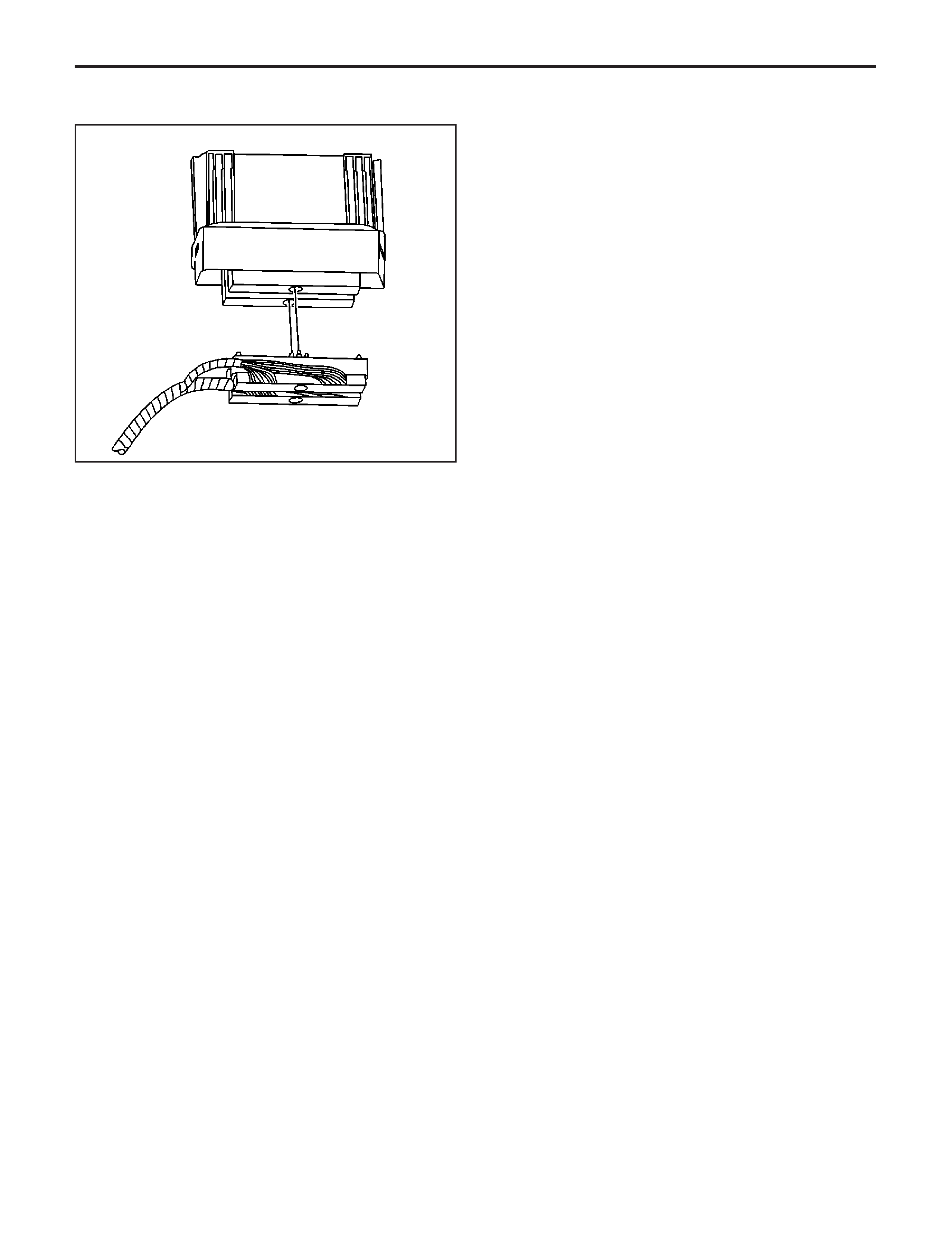
Repair Instructions
Engine Control Module (ECM)
Replacement
Engine control module (ECM) service should normally
consist of either ECM replacement or electrically
erasable programmable read only memory (EEPROM)
programming. If the diagnostic procedures require
ECM replacement, check the ECM first to see if
the correct part is being used.
Important: In order to prevent internal ECM damage,
the ignition must be OFF when you disconnect or
reconnect the power to the ECM. For example,
disconnect the power when you work with the following
components:
• A battery cable
• The ECM pigtail
• The ECM fuse
• The jumper cables
Important: When you diagnose or replace the ECM,
remove any debris from the ECM connector
surfaces before servicing the ECM module connector
gaskets. Ensure that the gaskets are installed
correctly. The gaskets prevent intrusion into the ECM.
Important: The replacement ECM MUST be
programmed.
Removal Procedure
Important: It is necessary to record the remaining
engine oil life. If the replacement module is not
programed with the remaining engine oil life, the
engine oil life will default to 100%. If the replacement
module is not programmed with the remaining
engine oil life, the engine oil will need to be changed
at 5000 km (3,000 mi) from the last engine oil
change.
1.UsingaTech 2 ,retrievethepercentageof
remaining engine oil. Record the remaining
engine oil life.
2. Remove the wheelhouse filler panel. Refer to
Fender, Insulator, Liner, Brake Caliper Cooling
Duct Replacement - Front
in Body Front End.
3. Remove the throttle actuator control (TAC)
module. Refer to
Transmission Control
Module (TCM) Replacement
in Automatic
Transmission – 4L60-E/4L65-E.
4. Disconnect the ECM electrical harness
connectors.
5. Loosen but do not remove the ECM rear retaining
fastener. Use the rear retaining fastener as an
anchor for the outer bracket.
6. Remove the front retaining fastener from the ECM.
7. Reposition the ECM outer bracket.
519848
EngineControls-6.0LEngine
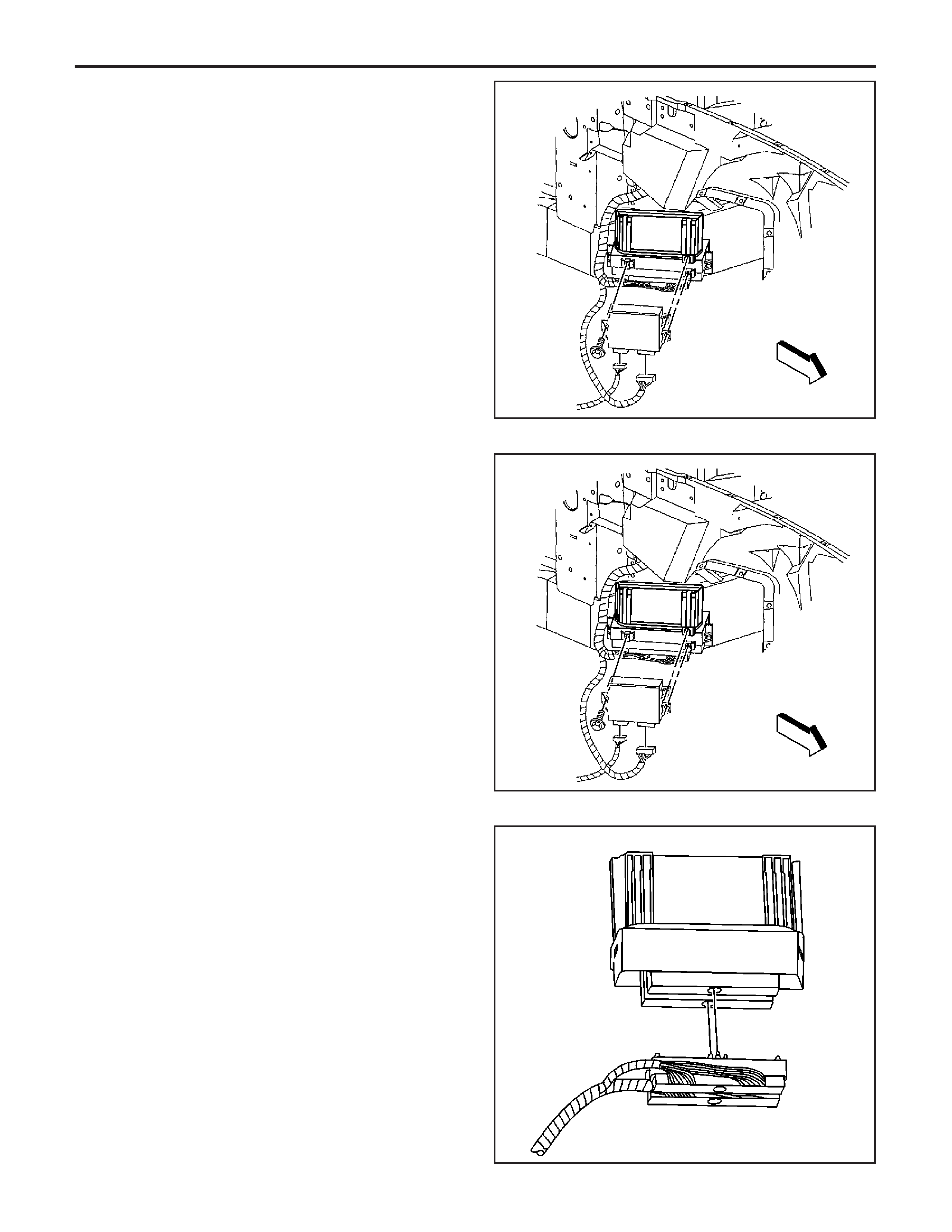
8. Remove the ECM from the bracket and the
vehicle.
Installation Procedure
1. Install the ECM to the ECM rear bracket.
2. Position the ECM front bracket.
Notice:
Refer to
Fastener Notice
in Cautions and
Notices.
3. Install the ECM front retaining fasteners.
Tighten
Tighten the ECM retaining fasteners to
2.0 N·m (17 lb in).
4. Connect the electrical connectors to the ECM.
Tighten
Tighten the ECM electrical connectors to
8 N·m (70 lb in).
5. Install the TAC module. Refer to
Transmission
Control Module (TCM) Replacement
in Automatic
Transmission – 4L60-E/4L65-E.
6. Install the wheelhouse filler panel. Refer to
Fender, Insulator, Liner, Brake Caliper Cooling
Duct Replacement - Front
in Body Front End.
7. If a new ECM is being installed, program the
ECM. Refer to
Control Module References
in
Computer/Integrating Systems.
519845
519845
519848
EngineEngineControls-6.0L

CKP System Variation Learn Procedure
1.InstallaTech 2 .
2. Monitor the engine control module (ECM) for
DTCswithaTech 2 .IfotherDTCsareset,
except DTC P0315, refer to
Diagnostic Trouble
Code (DTC) List - Vehicle
in Vehicle
DTC Information for the applicable DTC that set.
3. Select the crankshaft position (CKP) variation
learnprocedurewithaTech 2 .
4.TheTech 2 instructsyoutoperformthe
following:
4.1. Accelerate to wide open throttle (WOT).
4.2. Release throttle when fuel cut-off occurs.
4.3. Observe fuel cut-off for applicable engine.
4.4. Engine should not accelerate beyond
calibrated RPM value.
4.5. Release throttle immediately if value is
exceeded.
4.6. Block drive wheels.
4.7. Set parking brake.
4.8. DO NOT apply brake pedal.
4.9. Cycle ignition from OFF to ON.
4.10. Apply and hold brake pedal.
4.11. Start and idle engine.
4.12. Turn A/C OFF.
4.13. Vehicle must remain in Park or Neutral.
4.14.TheTech 2 monitorscertaincomponent
signals to determine if all the conditions are
met to continue with the procedure. The
Tech 2 onlydisplaysthecondition
thatinhibitstheprocedure.TheTech 2
monitors the following components:
• CKP sensors activity—If there is a CKP
sensor condition, refer to the applicable
DTC that set.
• Camshaft position (CMP) sensor
activity—If there is a CMP sensor
condition, refer to the applicable DTC
that set.
• Engine coolant temperature (ECT)—If
the ECT is not warm enough, idle
the engine until the engine coolant
temperature reaches the correct
temperature.
5. Enable the CKP system variation learn procedure
withaTech 2 .
Important: While the learn procedure is in progress,
release the throttle immediately when the engine starts
to decelerate. The engine control is returned to the
operator and the engine responds to throttle position
after the learn procedure is complete.
6. Accelerate to WOT.
7. Release when the fuel cut-off occurs.
8. Test in progress
9.TheTech 2 displaysLearnStatus:Learnedthis
ignition.IftheTech 2 indicatesthatDTCP0315
ran and passed, the CKP variation learn
procedureiscomplete.IftheTech 2 indicates
DTC P0315 failed or did not run, refer to
DTC P0315
. If any other DTCs set, refer to
Diagnostic Trouble Code (DTC) List - Vehicle
in
Vehicle DTC Information for the applicable
DTC that set.
10. Turn OFF the ignition for 30 seconds after the
learn procedure is completed successfully.
11. The CKP system variation learn procedure is also
required when the following service procedures
have been performed, regardless of whether
DTC P0315 is set:
• A CKP sensor replacement
• An engine replacement
• An ECM replacement
• A harmonic balancer replacement
• A crankshaft replacement
• Any engine repairs which disturb the CKP
sensor relationship
EngineControls-6.0LEngine
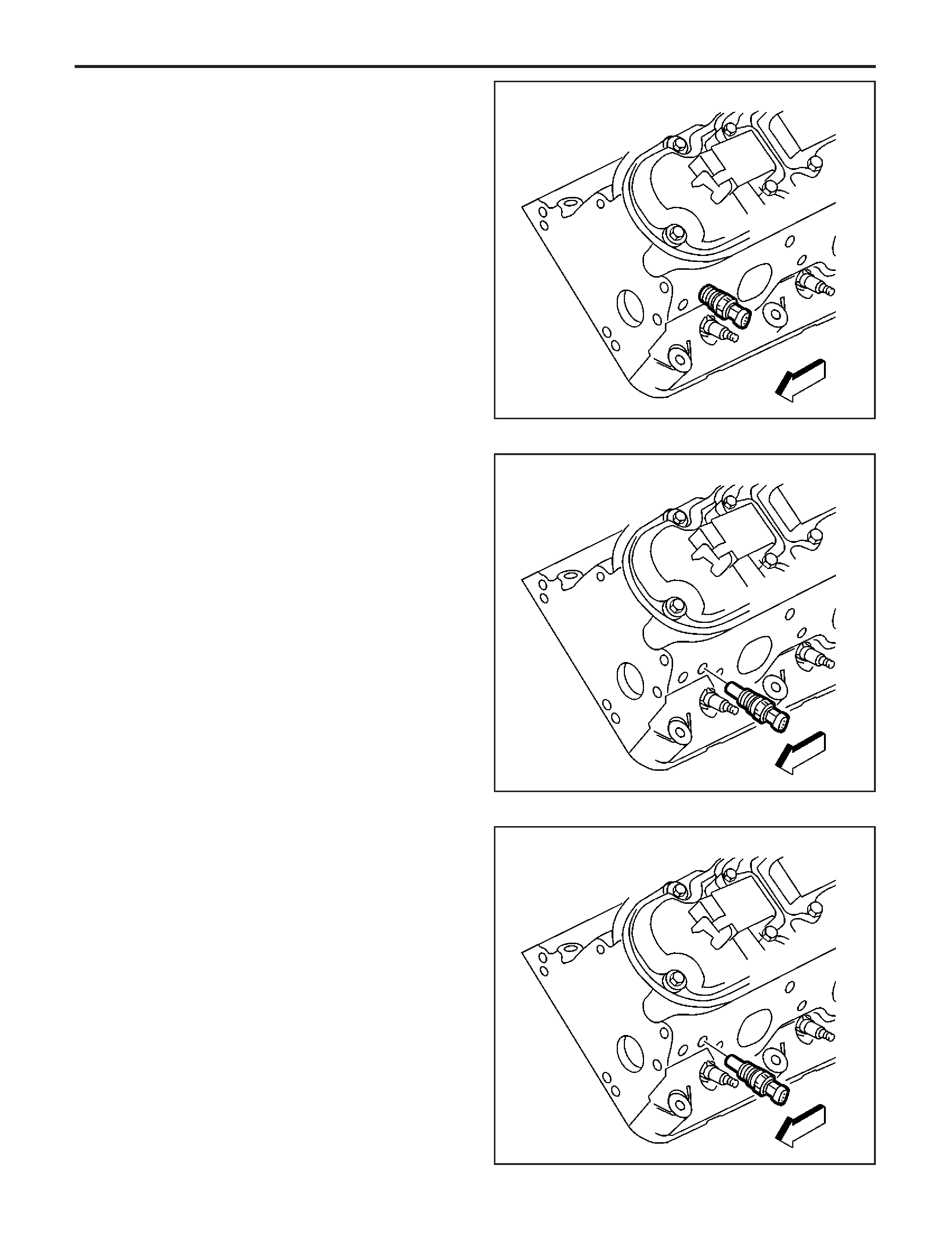
Engine Coolant Temperature (ECT) Sensor
Replacement
Removal Procedure
1. Turn OFF the ignition.
Caution: Refer to Vehicle Lifting Caution in
Cautions and Notices.
2. Raise the vehicle. Refer to
Lifting and Jacking the
Vehicle
in General Information.
3. Drain the engine coolant below the level of the
engine coolant temperature (ECT) sensor. Refer
to
Draining and Filling Cooling System
in
Engine Cooling.
4. Lower the vehicle.
5. Disconnect the harness connector from the ECT
sensor.
Notice:
SIO-ID = 5367 LMD = 18-aug-1995 Use care when
handling the coolant sensor. Damage to the coolant
sensor will affect the operation of the fuel control
system.
6. Remove the ECT sensor.
Installation Procedure
Notice:
Replacement
components must be the correct part number for
the application. Components requiring the use of the
thread locking compound, lubricants, corrosion
inhibitors, or sealants are identified in the service
procedure. Some replacement components may come
with these coatings already applied. Do not use
these coatings on components unless specified. These
coatings can affect the final torque, which may
affect the operation of the component. Use the correct
torque specification when installing components in
order to avoid damage.
Notice:
Usecarewhen
handling the coolant sensor. Damage to the coolant
sensor will affect the operation of the fuel control
system.
50967
50974
50974
EngineEngineControls-6.0L
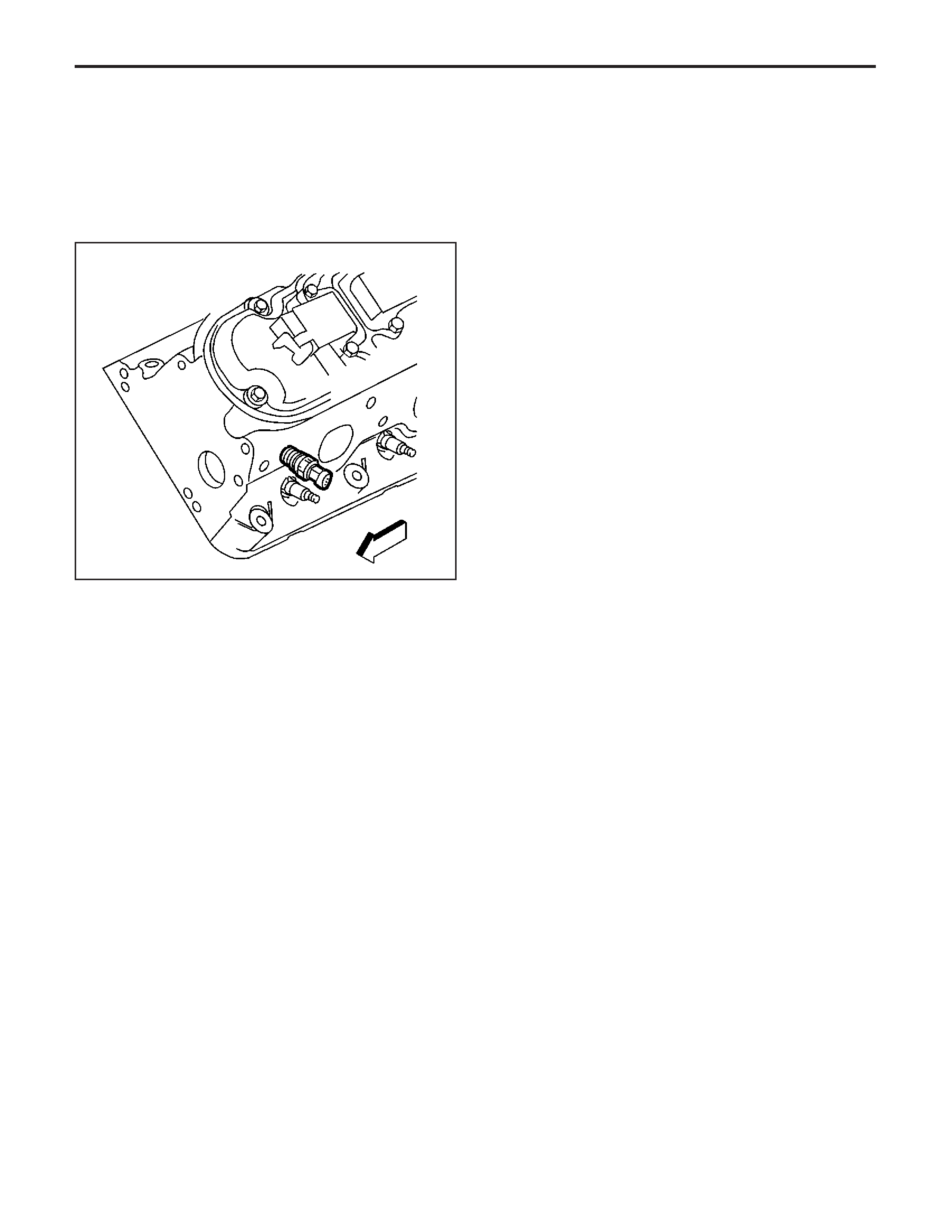
1. Coat the ECT sensor threads with sealer
P/N 12346004 (Canadian P/N 10953480) or the
equivalent.
Notice:
Refer to
Fastener Notice
in Cautions and
Notices.
2. Install the ECT sensor.
Tighten
Tighten the ECT sensor to 20 N·m (15 lb ft).
3. Connect the ECT sensor electrical connector.
4. Refill the engine coolant. Refer to
Draining and
Filling Cooling System
in Engine Cooling.
Mass Air Flow (MAF)/Intake Air
Temperature (IAT) Sensor Replacement
Removal Procedure
1. Disconnect the electrical connector 1 for the mass
airflow/airintaketemperature(MAF/IAT)sensor
2.Removethelines2fromtheairduct.
3.Loosentheairintakeductclamps.
4.Removetheairintakeductfromthe
throttle body.
5.RemovetheMAF/IATsensorfromtheair
cleanerhousing.
50967
EngineControls-6.0LEngine

Installation Procedure
Important: Ensure that the arrow on the MAF/IAT
sensor is pointing to the front, radiator, indicate
the proper air flow direction. The arrow must point
toward the engine.
1.InstalltheMAF/IATsensor5intheaircleaner
housing.
2.Installtheairintakeduct.
3.Positiontheclampsontheairintakeduct.
Notice:
Refer to
Fastener Notice
in Cautions
and Notices.
4.Tightentheclamps.
Tighten
TightenairintakeductandMAF/IATsensorto
4 N·m (35 lb in).
5.ReconnecttheMAF/IATelectricalconnector.
6.Reconnecttheelectricalconnector.
Manifold Absolute Pressure (MAP) Sensor
Replacement
Removal Procedure
1.Removetheoilfillercap.
2.Removetheenginecover.
3.Removethemanifoldabsolutepressure(MAP)
sensor.
4.Disconnecttheelectricalconnectorforthe
MAP sensor.
EngineEngineControls-6.0L
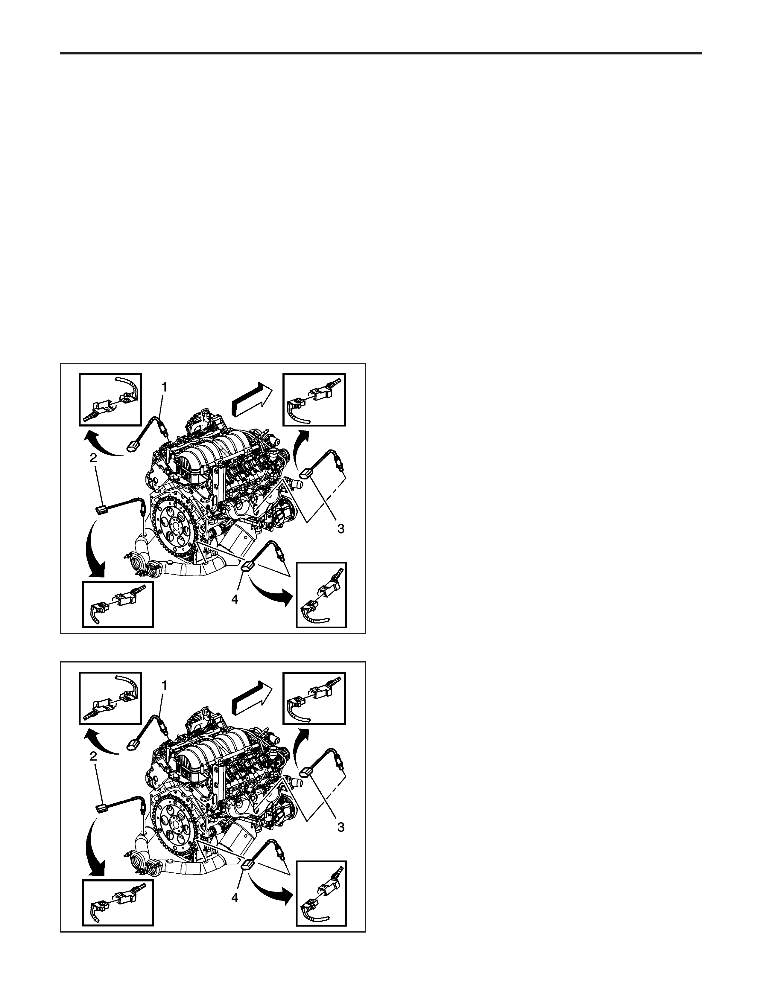
Installation Procedure
1. Reconnect the MAP sensor electrical
connectortotheenginewiringharness.
2.InstalltheMAPsensor.
3.Installenginecover.
4.Installtheoilfillercap.
Heated Oxygen Sensor (HO2S)
Replacement Bank 1 Sensor 1
Removal Procedure
1. Raise the vehicle. Refer to
Lifting and Jacking the
Vehicle
in General Information.
Notice:
Refer to
Heated Oxygen and Oxygen Sensor
Notice
in Cautions and Notices.
Notice:
Refer to
Excessive Force and Oxygen Sensor
Notice
in Cautions and Notices.
2. Disconnect the bank 1, oxygen sensor 1 (1)
electrical connector, from the engine wiring
harness electrical connector.
3. Remove the bank 1, oxygen sensor 1 (1) from the
exhaust manifold.
Installation Procedure
Important: Use special anti-seize compound on the
heated oxygen sensor threads. The compound
consists of graphite suspended in fluid and glass
beads. The graphite burns away, but the glass beads
remain, making the sensor easier to remove. New
or service sensors already have the compound applied
to the threads. If you remove an oxygen sensor and
if for any reason you must reinstall the same
oxygen sensor, apply the anti-seize compound to the
threads before reinstallation.
1. Coat the threads of the heated oxygen sensor
with the anti-seize compound P/N 5613695, or
the equivalent if necessary.
Notice:
Refer to
Fastener Notice
in Cautions and
Notices.
2. Install the heated oxygen sensor (1).
Tighten
1462140
1462140
EngineControls-6.0LEngine
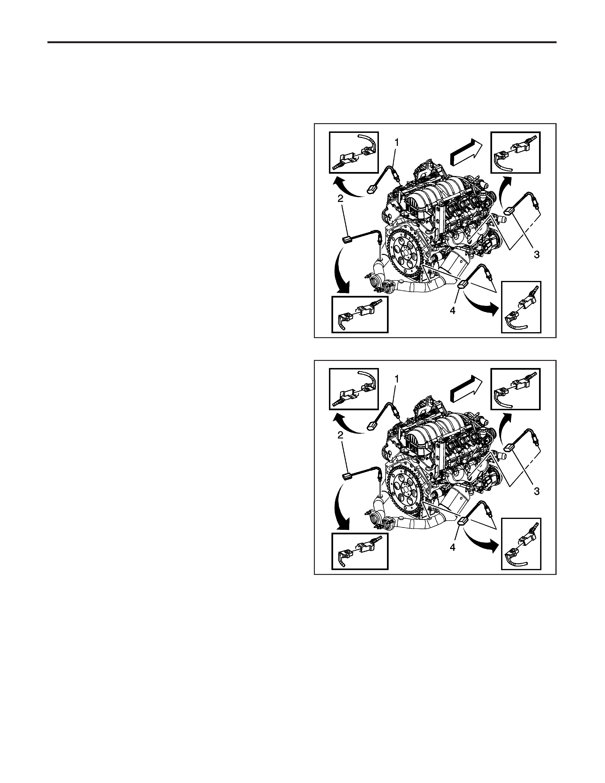
Tighten the HO2S to 41 N·m (30 lb ft).
3. Reconnect the bank 1, oxygen sensor (4),
electrical connector to the engine wiring harness
electrical connector.
4. Lower the vehicle.
Heated Oxygen Sensor (HO2S)
Replacement Bank 1 Sensor 2
Removal Procedure
1. Raise the vehicle. Refer to
Lifting and Jacking the
Vehicle
in General Information.
Notice:
Refer to
Heated Oxygen and Oxygen Sensor
Notice
in Cautions and Notices.
Notice:
Refer to
Excessive Force and Oxygen Sensor
Notice
in Cautions and Notices.
2. Disconnect the bank 1, oxygen sensor 2 (2),
electrical connector from the engine harness.
3. Remove the bank 1, oxygen sensor 2 (2), in the
catalytic convertor.
Installation Procedure
Important: Use special anti-seize compound on the
heated oxygen sensor threads. The compound
consists of graphite suspended in fluid and glass
beads. The graphite burns away, but the glass beads
remain, making the sensor easier to remove. New
or service sensors already have the compound applied
to the threads. If you remove an oxygen sensor and
if for any reason you must reinstall the same
oxygen sensor, apply the anti-seize compound to the
threads before reinstallation.
1. Coat the threads of the heated oxygen sensor
with the anti-seize compound P/N 5613695, or
the equivalent if necessary.
Notice:
Refer to
Fastener Notice
in Cautions and
Notices.
2. Install the bank 1, oxygen sensor 2 (2), in the
catalytic convertor.
Tighten
Tighten the oxygen sensor to 41 N·m (30 lb ft).
3. Reconnect the bank 1, oxygen sensor 2 (2),
electrical connector to the engine wiring
harness electrical connector.
4. Lower the vehicle.
1462140
1462140
EngineEngineControls-6.0L
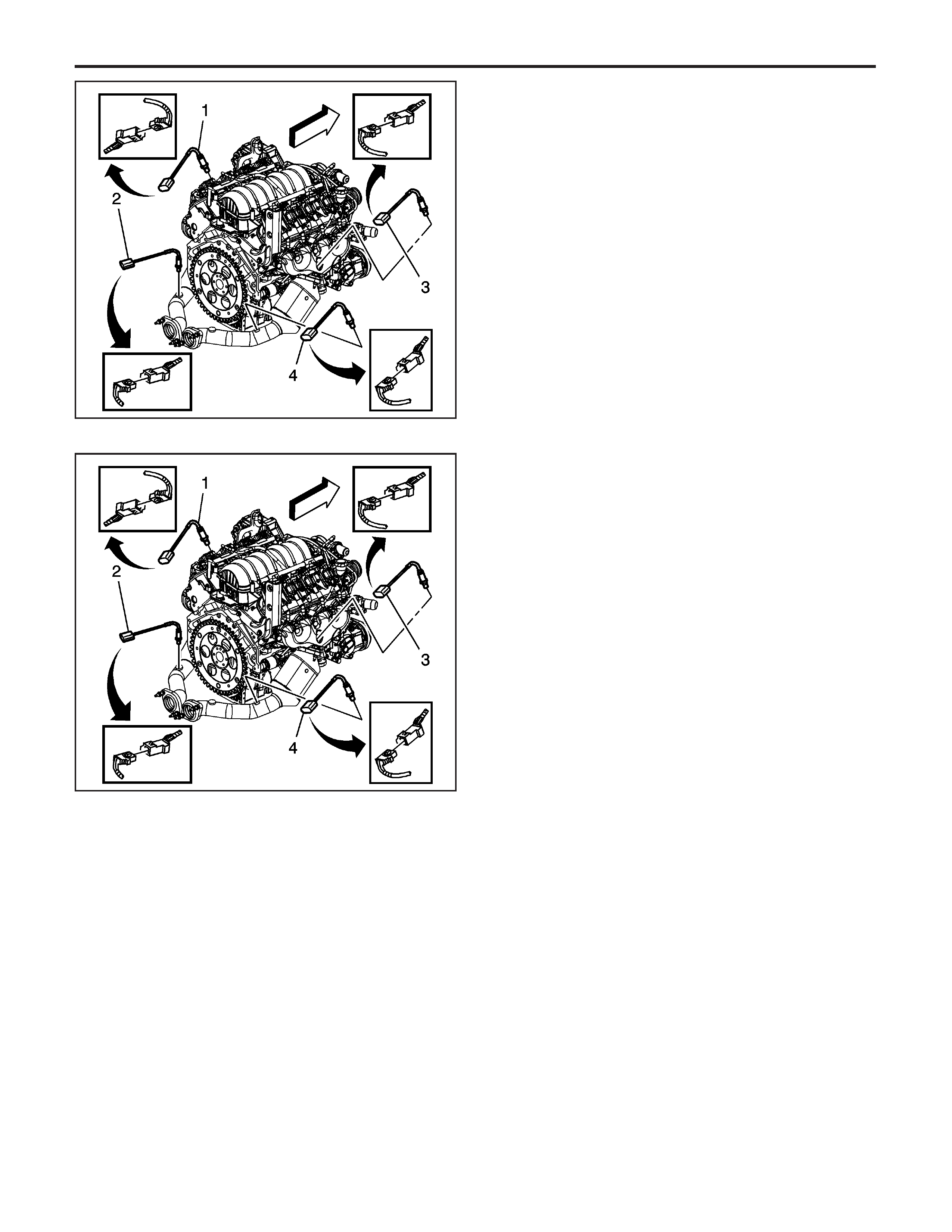
Heated Oxygen Sensor (HO2S)
Replacement Bank 2 Sensor 1
Removal Procedure
1. Raise the vehicle. Refer to
Lifting and Jacking the
Vehicle
in General Information.
2. Disconnect bank 2, oxygen sensor 1 (3), electrical
connector from the engine harness electrical
connector.
Notice:
Refer to
Heated Oxygen and Oxygen Sensor
Notice
in Cautions and Notices.
Notice:
Refer to
Excessive Force and Oxygen Sensor
Notice
in Cautions and Notices.
3. Remove the bank 2, oxygen sensor 1 (3), from the
catalytic convertor.
Installation Procedure
Important: Use special anti-seize compound on the
heated oxygen sensor threads. The compound
consists of graphite suspended in fluid and glass
beads. The graphite burns away, but the glass beads
remain, making the sensor easier to remove. New
or service sensors already have the compound applied
to the threads. If you remove an oxygen sensor and
if for any reason you must reinstall the same
oxygen sensor, apply the anti-seize compound to the
threads before reinstallation.
1. Coat the threads of the bank 2, oxygen sensor
1 (3) with the anti-seize compound P/N 5613695,
or the equivalent if necessary.
Notice:
Refer to
Fastener Notice
in Cautions and
Notices.
2. Install the bank 2, oxygen sensor 1 (3), in the
exhaust manifold.
Tighten
Tighten the oxygen sensor to 41 N·m (30 lb ft).
3. Reconnect the bank 2, oxygen sensor 1 (3),
electrical connector to the engine wiring
harness electrical connector.
4. Lower the vehicle.
1462140
1462140
EngineControls-6.0LEngine
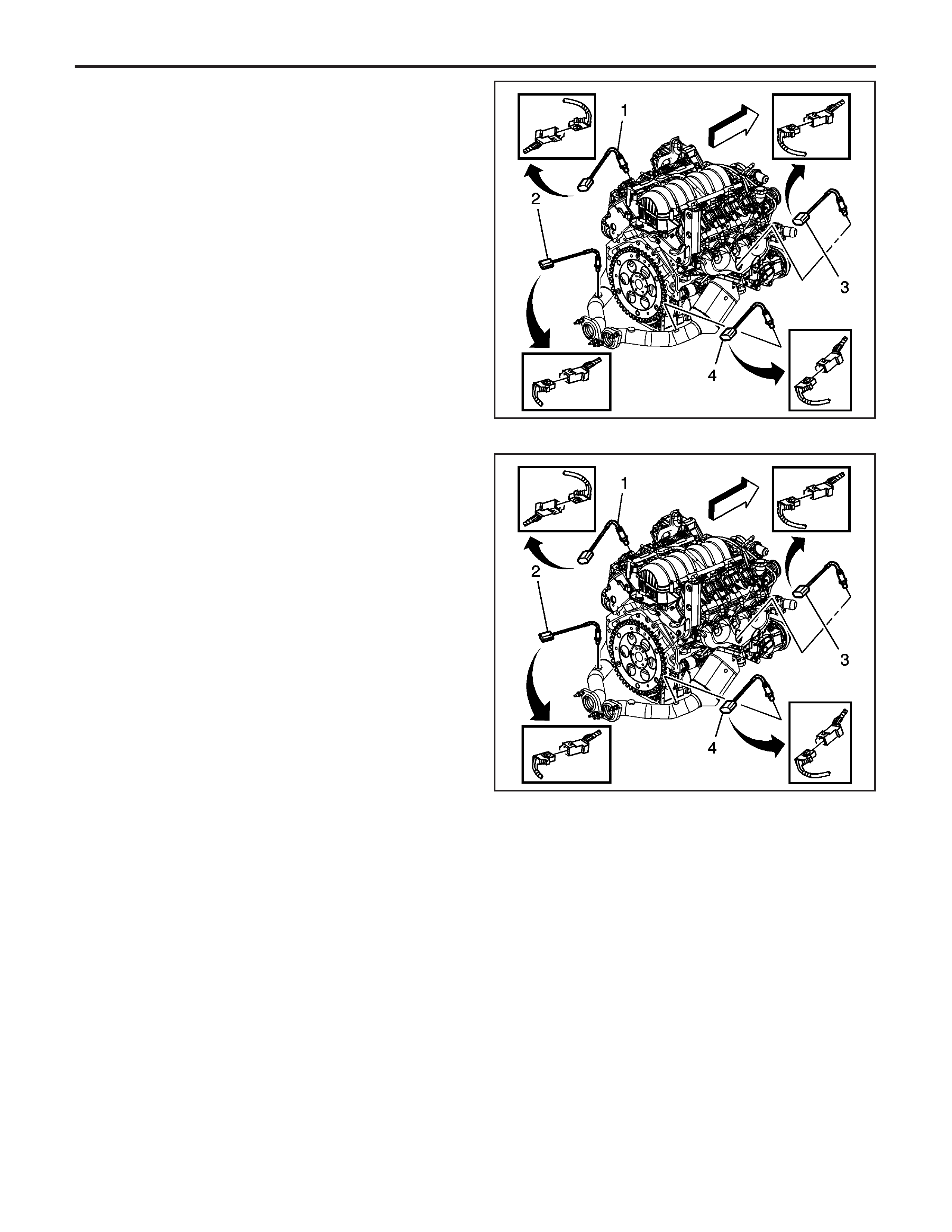
Heated Oxygen Sensor (HO2S)
Replacement Bank 2 Sensor 2
Removal Procedure
1. Raise the vehicle. Refer to
Lifting and Jacking the
Vehicle
in General Information.
2. Disconnect the bank 2, oxygen sensor 2 (4),
electrical connector from the engine wiring
harness connector.
Notice:
Refer to
Heated Oxygen and Oxygen Sensor
Notice
in Cautions and Notices.
Notice:
Refer to
Excessive Force and Oxygen Sensor
Notice
in Cautions and Notices.
3. Remove the bank 2, oxygen sensor 2 (4), from
the catalytic converter.
Installation Procedure
Important: Use special anti-seize compound on the
heated oxygen sensor threads. The compound
consists of graphite suspended in fluid and glass
beads. The graphite burns away, but the glass beads
remain, making the sensor easier to remove. New
or service sensors already have the compound applied
to the threads. If you remove an oxygen sensor and
if for any reason you must reinstall the same
oxygen sensor, apply the anti-seize compound to the
threads before reinstallation.
1. Coat the threads of the oxygen sensor 2 with the
anti-seize compound P/N 5613695, or the
equivalent if necessary.
Notice:
Refer to
Fastener Notice
in Cautions and
Notices.
2. Install the bank 2, oxygen sensor 2 (4), in the
catalytic converter.
Tighten
Tighten the bank 2, oxygen senor 2 to 41
N·m (30 lb ft).
3. Reconnect the bank 2, oxygen sensor 2 (4),
electrical connector to the engine wiring
harness electrical connector.
4. Lower the vehicle.
1462140
1462140
EngineEngineControls-6.0L
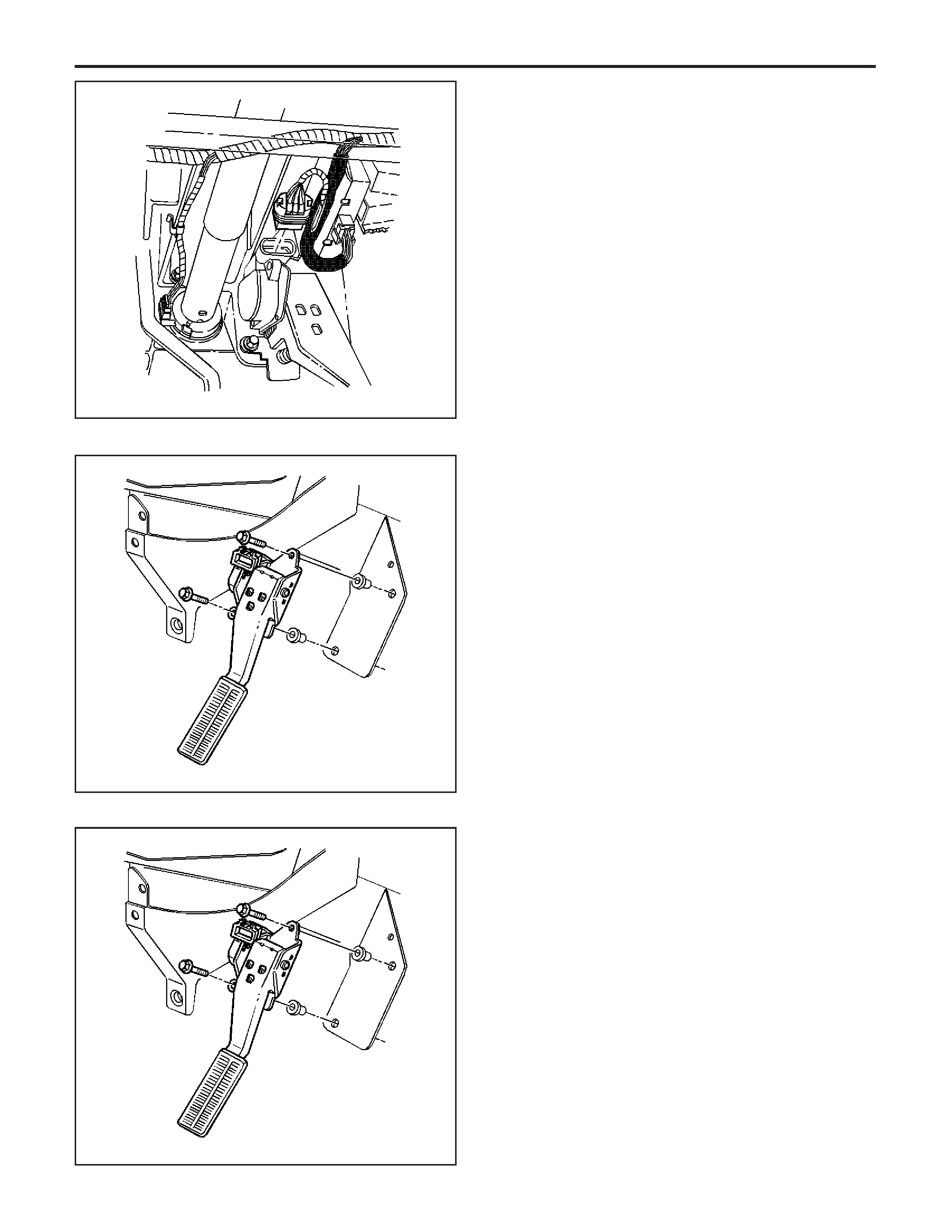
Accelerator Pedal Position (APP) Sensor
Replacement
Removal Procedure
Notice:
Handlethe
electronic throttle control components carefully.
Use cleanliness in order to prevent damage. Do not
drop the electronic throttle control components. Do not
roughly handle the electronic throttle control
components. Do not immerse the electronic throttle
control components in cleaning solvents of any type.
1. Remove the left instrument panel (I/P) on the
lower closeout insulator panel. Refer to
Closeout/Insulator Panel Replacement -
Instrument Panel (I/P) Lower
in Instrument Panel,
Gages and Console.
2. Disconnect the electrical connector of the
accelerator pedal sensor module.
3. Remove the accelerator pedal mounting bolts.
4. Remove the accelerator pedal.
Installation Procedure
1. Install the accelerator pedal to the steering
column support bracket.
Notice:
Refer to
Fastener Notice
in Cautions and
Notices.
Important: Always use a torque wrench in order to
obtain the proper torque.
2. Install the accelerator pedal mounting bolts.
Tighten
Tighten the accelerator pedal mounting bolts to
20 N·m (15 lb ft).
43534
43535
43535
EngineControls-6.0LEngine
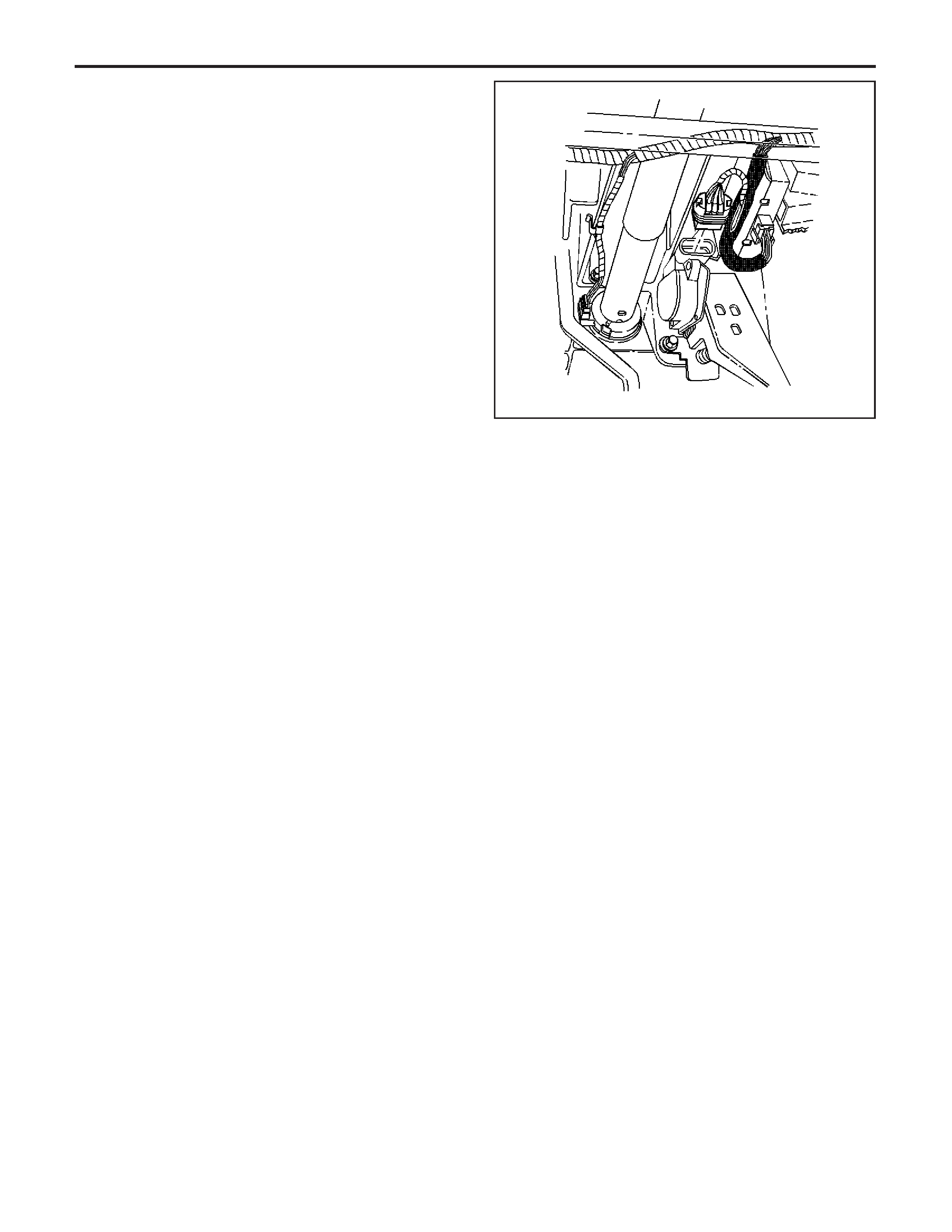
3. Connect the accelerator pedal sensor module
electrical connector.
4. Inspect for complete throttle opening, and throttle
closing positions by operating the accelerator
pedal. Monitor the throttle angles using a
Tech 2 .Theacceleratorpedalshouldoperate
freely without binding between full closed
throttle, and wide open throttle.
5. Inspect for an incorrect carpet fit under the
accelerator pedal.
6. Install the left I/P on the lower closeout insulator
panel. Refer to
Closeout/Insulator Panel
Replacement - Instrument Panel (I/P) Lower
in
Instrument Panel, Gages and Console.
Throttle Body Assembly Replacement
Removal Procedure
Notice:
Handlethe
electronic throttle control components carefully.
Use cleanliness in order to prevent damage. Do not
drop the electronic throttle control components. Do not
roughly handle the electronic throttle control
components. Do not immerse the electronic throttle
control components in cleaning solvents of any type.
1. An 8-digit part identification number is stamped on
the throttle body casting. Refer to this number if
servicing, or if a part replacement is required.
Important: Cover or plug any openings when servicing
the throttle body in order to prevent possible
contamination.
2. Disconnect the intake air temperature sensor
electrical connector.
3. Remove the air intake duct.
43534
EngineEngineControls-6.0L
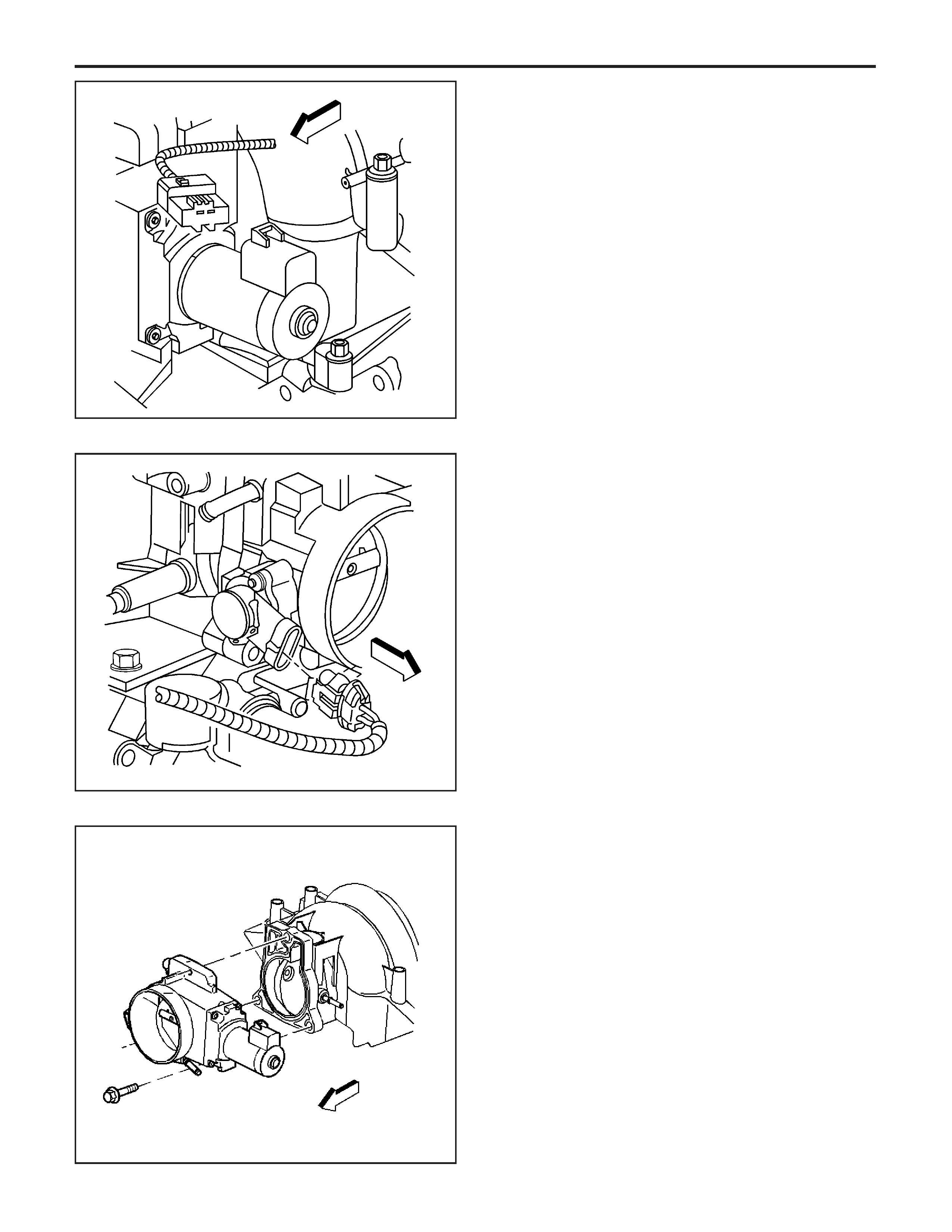
4. Disconnect the air control valve electrical
connector.
5. Disconnect the throttle position (TP) sensor
electrical connector.
6. Disconnect the crankcase ventilation hose from
the throttle body.
7. Remove the throttle body attaching bolts.
8. Remove the throttle body and the gasket.
Important: Do not reuse the throttle body gasket.
Install a new gasket during assembly.
9. Discard the throttle body gasket.
10. Inspect the crankcase ventilation hose and the
tube. Replace any damaged components.
1461904
1461901
43567
EngineControls-6.0LEngine
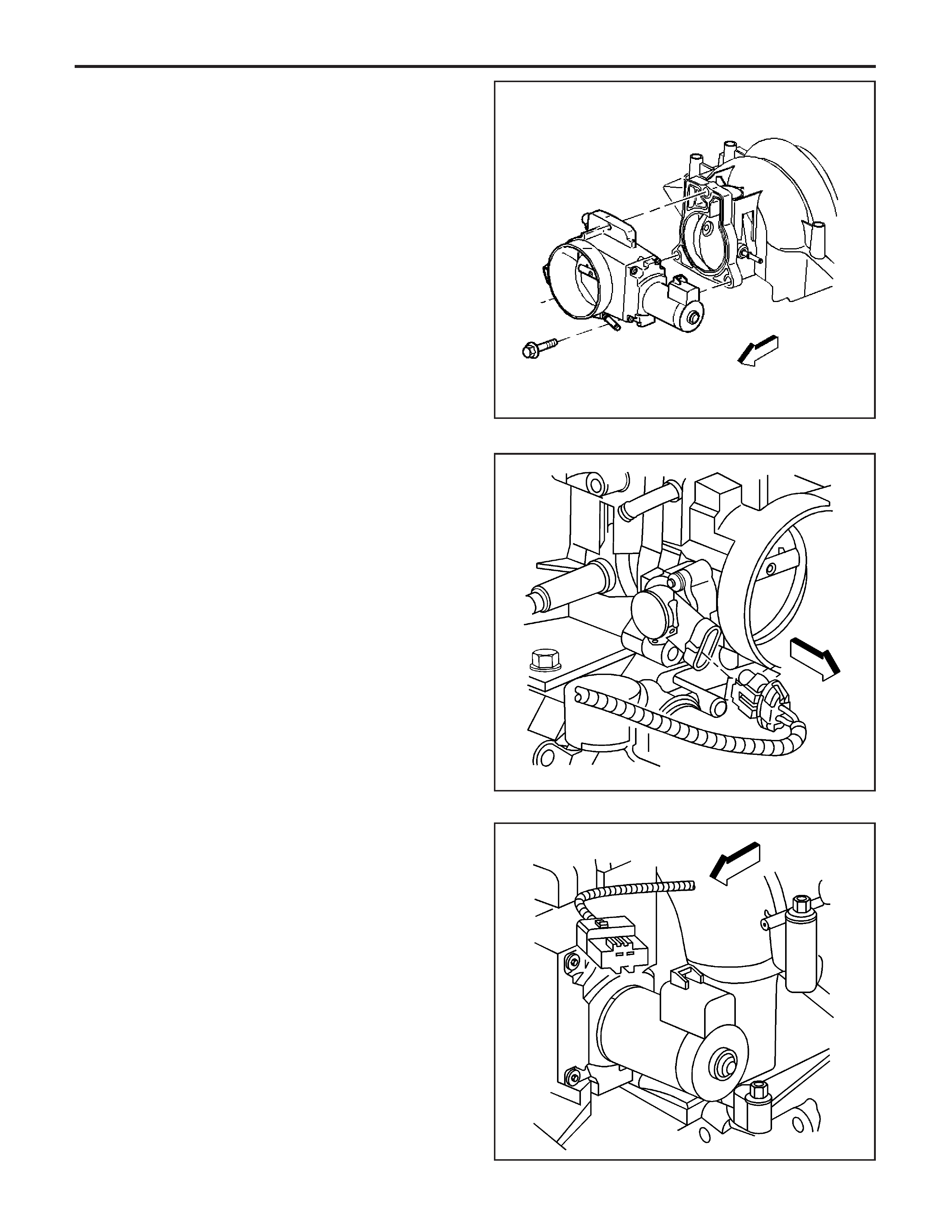
Installation Procedure
1. Install a new throttle body gasket.
2. Install the throttle body assembly.
Notice:
Refer to the
Fastener Notice
in Cautions and
Notices.
Important: Always use a torque wrench in order to
obtain the proper torque.
3. Install the throttle body attaching bolts.
Tighten
Tighten the throttle body bolts to 10 N·m (89 lb in).
4. Connect the TP sensor electrical connector.
5. Connect the crankcase ventilation hose to the
throttle body.
Important: Ensure that the air control valve electrical
connector and the connector seal are properly
installed and not damaged.
6. Connect the air control valve electrical connector.
43567
1461901
1461904
EngineEngineControls-6.0L

7. Install the air intake duct.
8. Connect the intake air temperature sensor
electrical connector.
9. Check for complete throttle opening and closing
positions by operating the accelerator pedal.
Monitorthethrottleangles,usingaTech 2 .The
accelerator pedal should operate freely without
binding between full closed throttle and wide open
throttle.
10. Start the engine.
Throttle Body Cleaning Procedure
Caution:TurnOFF
the ignition before inserting fingers into the throttle
bore. Unexpected movement of the throttle
blade could cause personal injury.
1. Remove the air intake duct.
Notice:
Donotinsert
any tools into the throttle body bore in order to
avoid damage to the throttle valve plate.
2. Inspect the throttle body bore and the throttle
valve plate for deposits. If necessary, open the
throttle valve to inspect all surfaces.
Notice:
Donotuseany
solvent that contains Methyl Ethyl Ketone (MEK).
This solvent may damage fuel system components.
3. Clean the throttle body bore and the throttle valve
plate using a clean shop towel with an appropriate
cleaning substance, such one of the following:
• GM Top Engine Cleaner
• P/N 1052626
• AC-Delco Carburetor Tune-Up Conditioner
• P/N X66–P
4. Install the air intake duct.
EngineControls-6.0LEngine
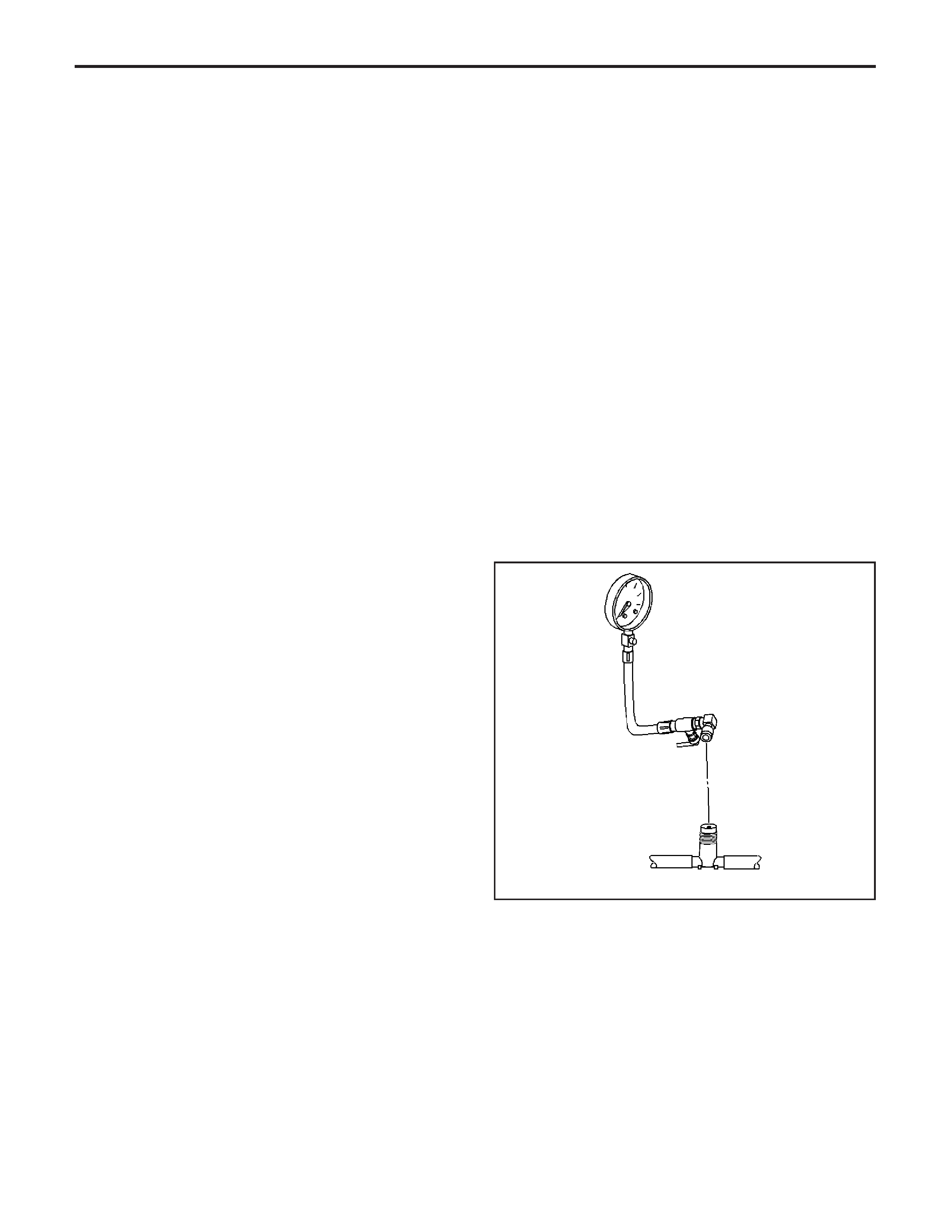
Fuel Pressure Relief Procedure
Tool Required
J 34730-1A
Fuel Pressure Gage
Caution:Removethe
fuel tank cap and relieve the fuel system pressure
before servicing the fuel system in order to
reduce the risk of personal injury. After you relieve
the fuel system pressure, a small amount of fuel
may be released when servicing the fuel lines, the
fuel injection pump, or the connections. In order
to reduce the risk of personal injury, cover the fuel
system components with a shop towel before
disconnection. This will catch any fuel that may
leak out. Place the towel in an approved container
when the disconnection is complete.
1. Turn the ignition OFF.
Caution: Refer to the Battery Disconnect Caution
in Cautions and Notices.
2. Disconnect the negative battery cable in order to
avoid possible fuel discharge if an accidental
attempt is made to start the engine.
3. Loosen the fuel filler cap in order to relieve the
fuel tank vapor pressure.
4. Remove the left fuel rail cover.
5. Connect the
J 34730-1A
to the fuel pressure
connection. Wrap a shop towel around the fitting
while connecting the gauge in order to avoid
spillage.
6. Install the bleed hose of the gauge into an
approved container.
7. Open the valve on the gauge to bleed the system
pressure. The fuel connections are now safe for
servicing.
8. Drain any fuel remaining in the gauge into an
approved container.
180378
EngineEngineControls-6.0L
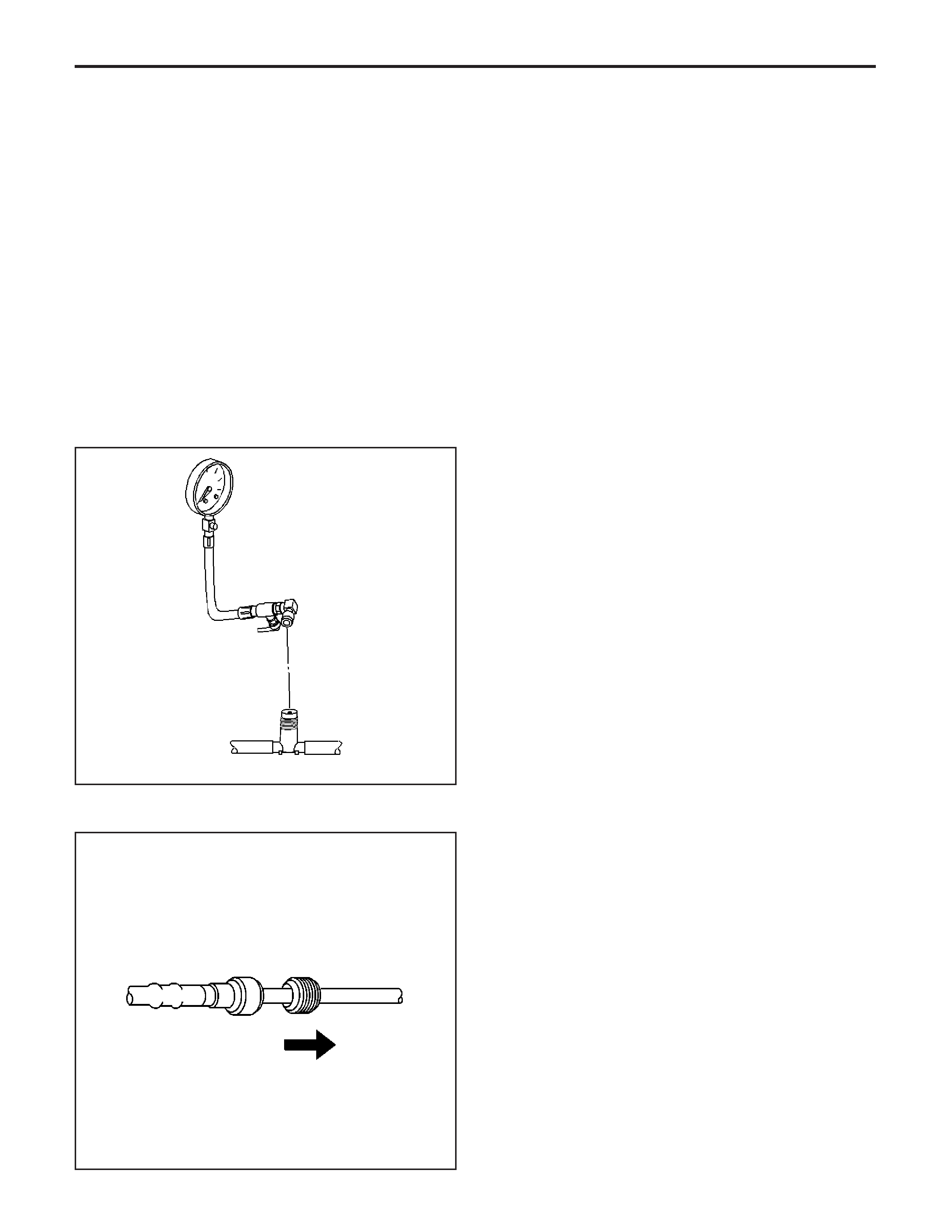
Fuel Pressure Gage Installation and
Removal
Installation Procedure
Caution: Refer to Gasoline/Gasoline Vapors
Caution in Cautions and Notices.
1. Remove the left fuel rail cover.
Caution: Refer to Fuel Gage Leak Caution in
Cautions and Notices.
Notice:
Refer to
Fuel and Evaporative
Emission (EVAP) Hose/Pipe Connection Cleaning
Notice
in Cautions and Notices.
2. Install the fuel pressure gage to the fuel pressure
service connection, located on the fuel rail.
3. Turn ON the ignition.
Caution: Refer to Fuel Storage Caution in Cautions
and Notices.
4. Place the bleed hose of the fuel pressure gage
into an approved gasoline container.
5. Open the bleed valve on the fuel pressure gage in
order to bleed the air from the fuel pressure gage.
6.CommandthefuelpumpONwithaTech 2 .
7. Close the bleed valve on the fuel pressure gage.
8. Inspect for fuel leaks.
Quick Connect Fitting(s) Service (Metal
Collar)
Tools Required
•
J 34730-1A
Fuel Pressure Gage
•
J 37088-A
Tool Set, Fuel Line Quick-Connect
Separator
Removal Procedure
1. Relieve the fuel system pressure before servicing
any fuel system connection. Refer to the
Fuel
Pressure Relief Procedure
.
2. Slide the dust cover from the quick-connect fitting.
180378
12773
EngineControls-6.0LEngine
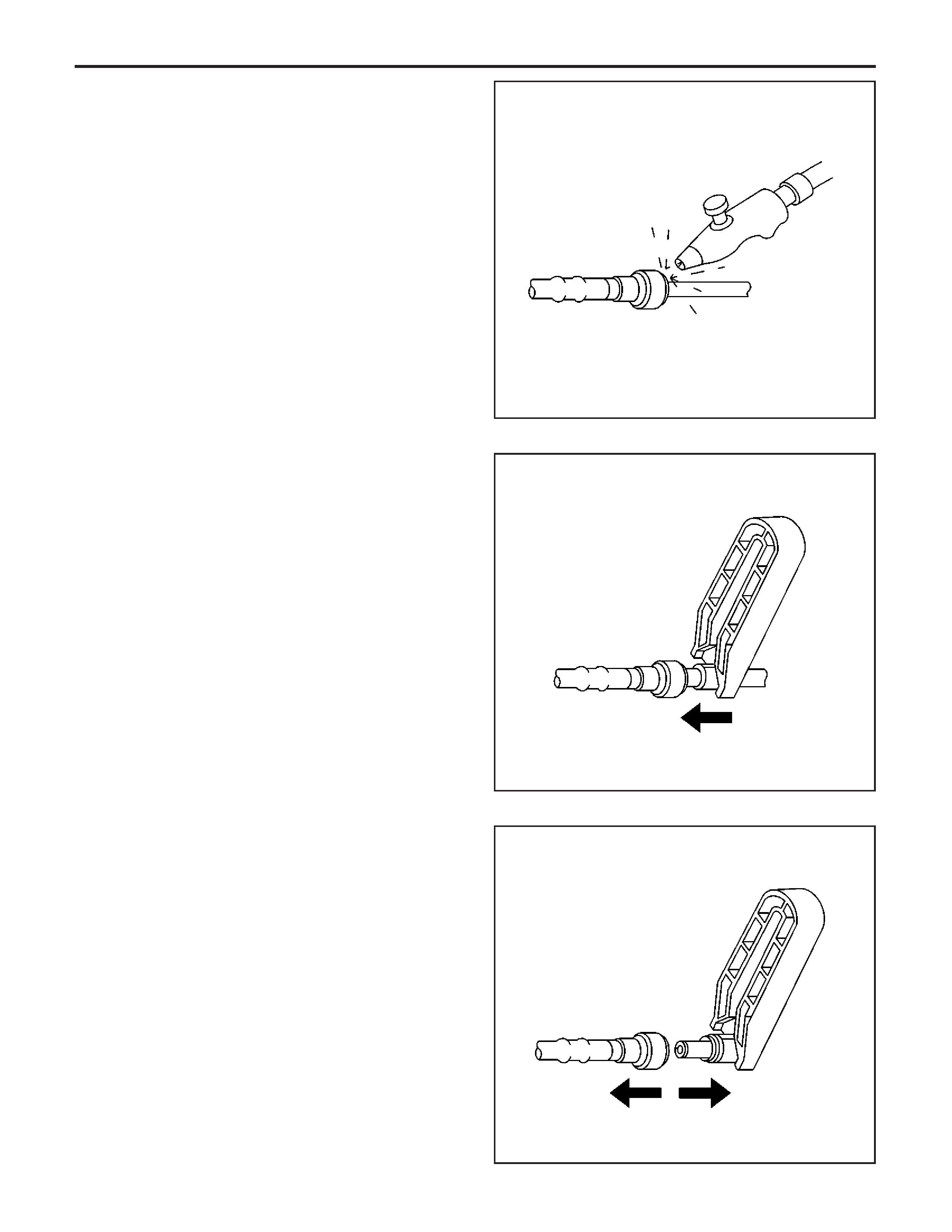
Caution:Wearsafety
glasses when using compressed air in order to
prevent eye injury.
3. Blow any dirt out of the fitting, using
compressed air.
4. Choose the correct tool from the
J 37088-A
Tool
Set for the size of the fitting. Insert the tool into
the female connector, then push inward in order to
release the locking tabs.
5. Pull the connection apart.
Notice:
Ifnecessary,
remove rust or burrs from the fuel pipes with an emery
cloth. Use a radial motion with the fuel pipe end in
order to prevent damage to the O-ring sealing surface.
Use a clean shop towel in order to wipe off the
male tube ends. Inspect all the connections for dirt
and burrs. Clean or replace the components and
assemblies as required.
6. Using a clean shop towel, wipe off the male
pipe end.
7. Inspect both ends of the fitting for dirt and burrs.
Clean or replace the components as required.
12776
12780
12782
EngineEngineControls-6.0L
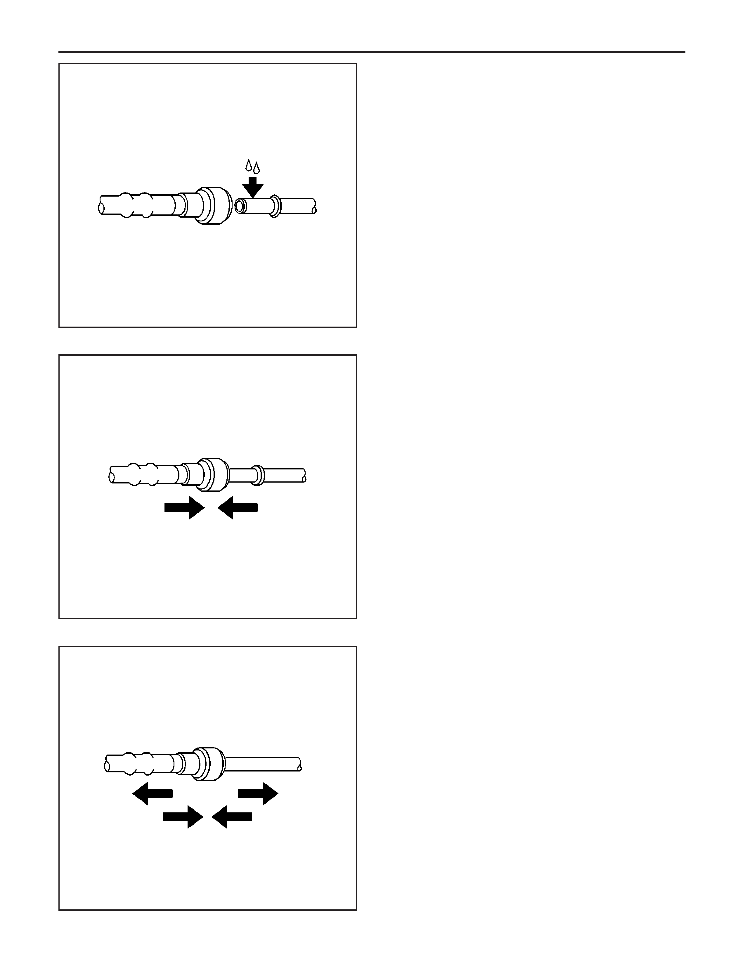
Installation Procedure
Caution:Always
apply a few drops of clean engine oil to the male
pipe ends before connecting the fuel pipe
fittings in order to reduce the risk of fire and
personal injury. This will ensure proper
reconnection and prevent a possible fuel leak.
During normal operation, the O-rings located in the
female connector will swell and may prevent
proper reconnection if not lubricated.
1. Apply a few drops of clean engine oil to the male
pipe end.
2. Push both sides of the fitting together in order to
cause the retaining tabs to snap into place.
3. Once installed, pull on both sides of the fitting in
order to make sure the connection is secure.
12784
12786
12787
EngineControls-6.0LEngine
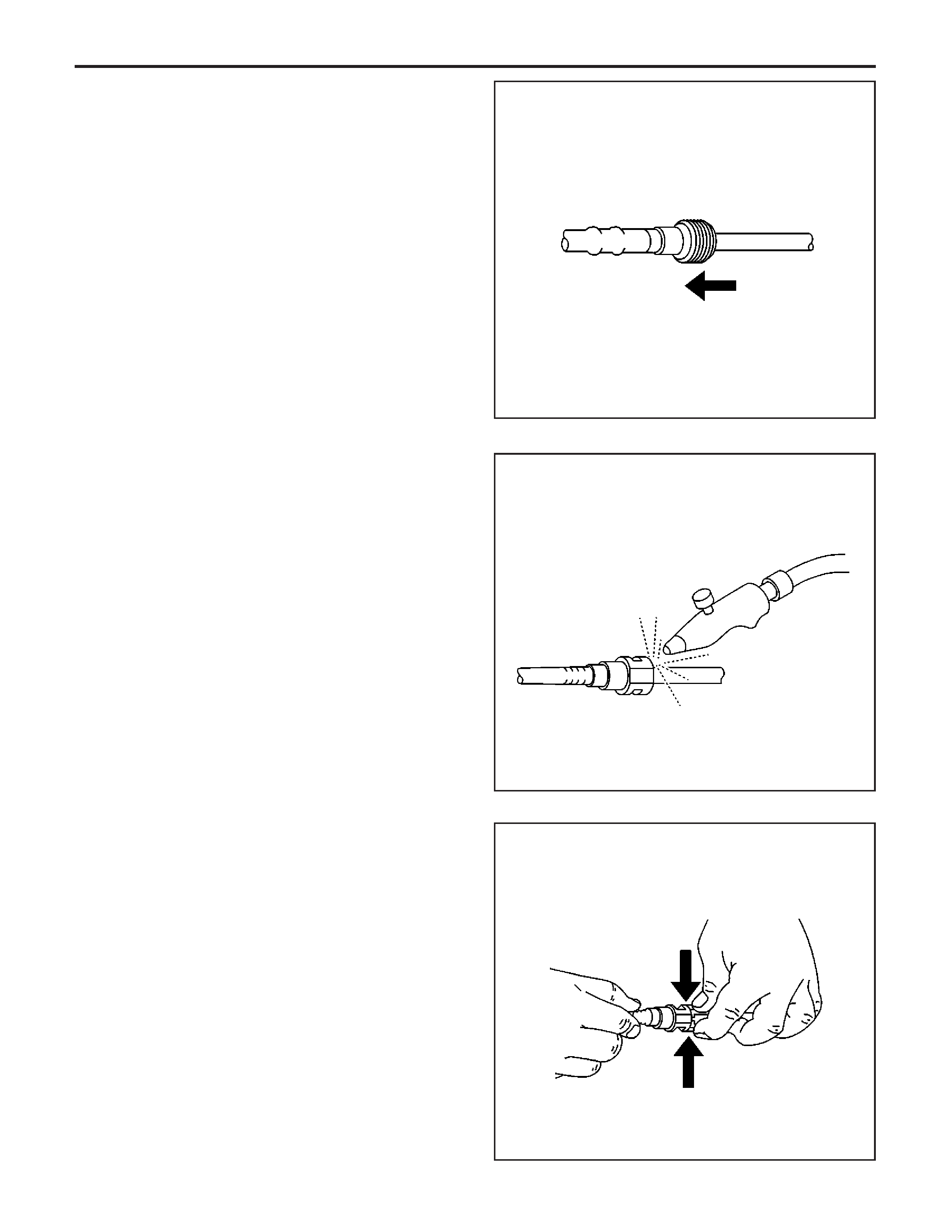
4. Reposition the dust cover over the quick-connect
fitting.
Quick Connect Fitting(s) Service (Plastic
Collar)
Tool Required
J 34730-1A
Fuel Pressure Gage
Removal Procedure
1. Relieve the fuel system pressure before servicing
any fuel system connection. Refer to the
Fuel
Pressure Relief Procedure
.
Caution:Wearsafety
glasses when using compressed air in order to
prevent eye injury.
2. Using compressed air, blow any dirt out of the
quick-connect fitting.
Important: Plastic quick connect fittings can be
released either by squeezing the plastic retainer
release tabs (step 3) or by using the appropriate
J 37088-A
Fuel Line Quick Connect Separator Tool
(step 4).
3. Squeeze the plastic retainer release tabs.
12789
155410
12777
EngineEngineControls-6.0L
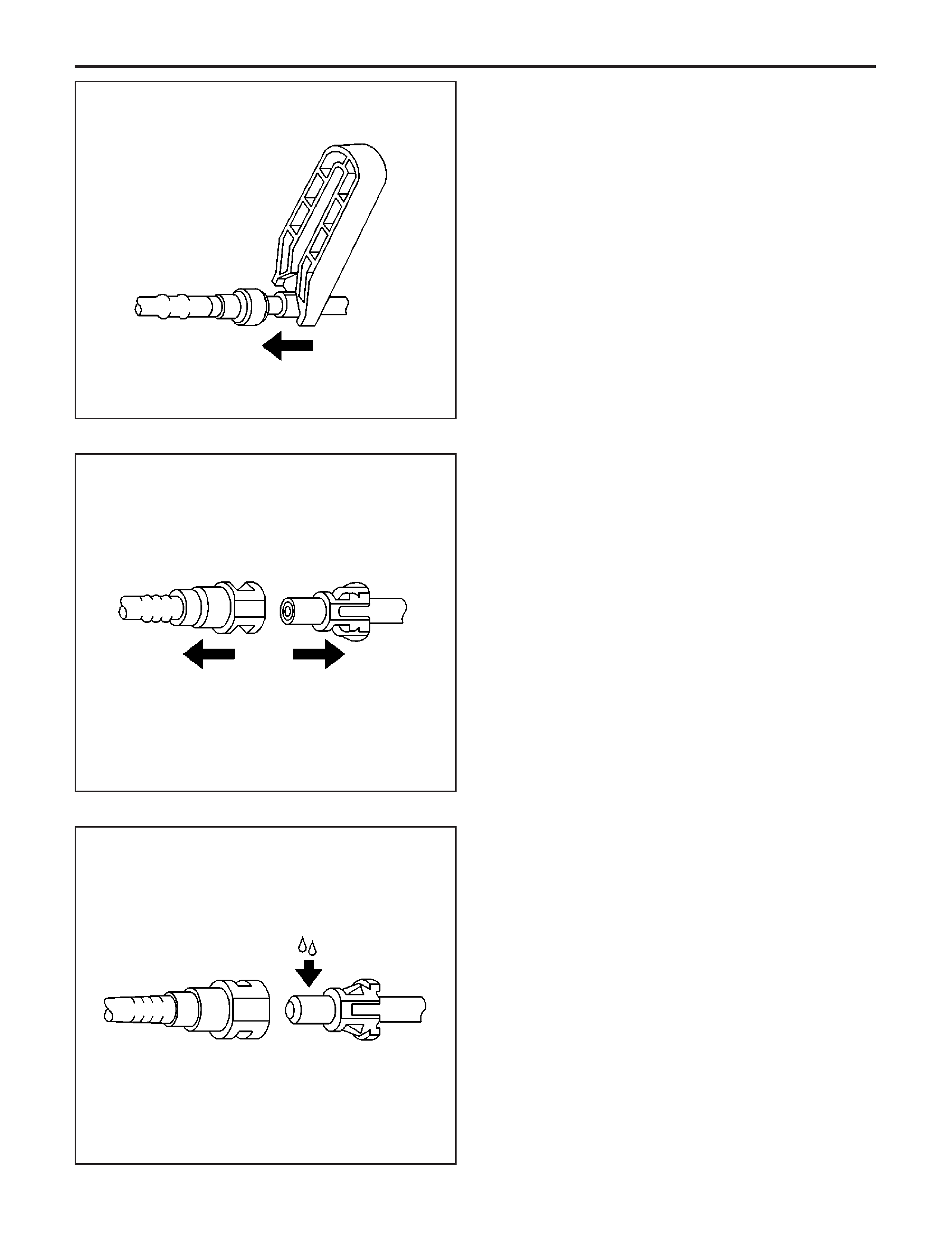
4. Choose the correct tool from the
J 37088-A
Tool
Set for the size of the fitting. Insert the tool into
the female connector, then push inward in order to
release the locking tabs. The plastic retainer will
remain on the female connector.
5. Pull the connection apart.
Installation Procedure
Caution:Always
apply a few drops of clean engine oil to the male
pipe ends before connecting the fuel pipe
fittings in order to reduce the risk of fire and
personal injury. This will ensure proper
reconnection and prevent a possible fuel leak.
During normal operation, the O-rings located in the
female connector will swell and may prevent
proper reconnection if not lubricated.
1. Apply a few drops of clean engine oil to the male
fuel pipe end.
12780
12778
155425
EngineControls-6.0LEngine
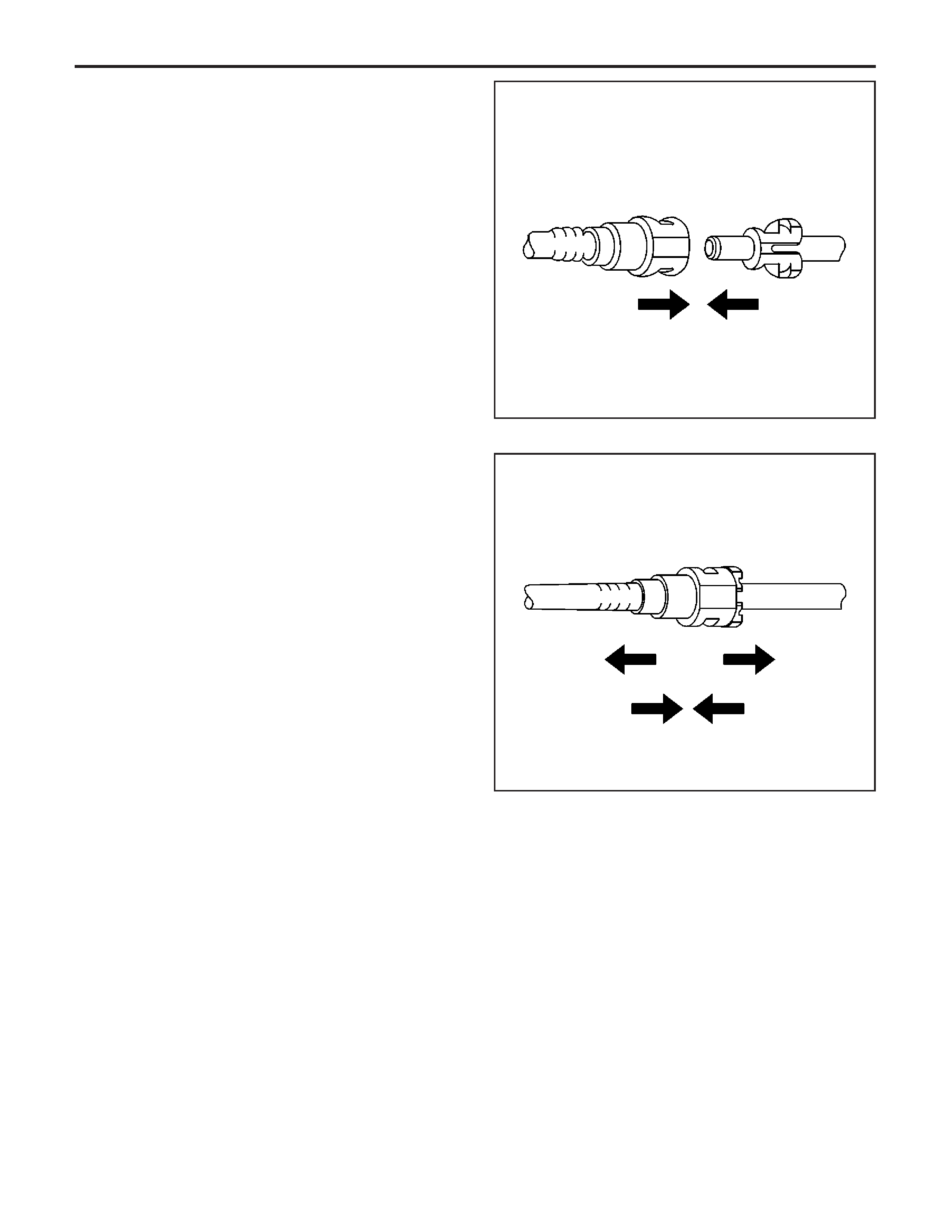
2. Push both sides of the quick-connect fitting
together in order to cause the retaining
tabs/fingers to snap into place.
3. Once installed, pull on both sides of the
quick-connect fitting in order to make sure the
connection is secure.
21855
155399
EngineEngineControls-6.0L

Fuel Tank Draining Procedure
For all information on HSV VZ Fuel Tank refer to Holden VZ Service Information
EngineControls-6.0LEngine
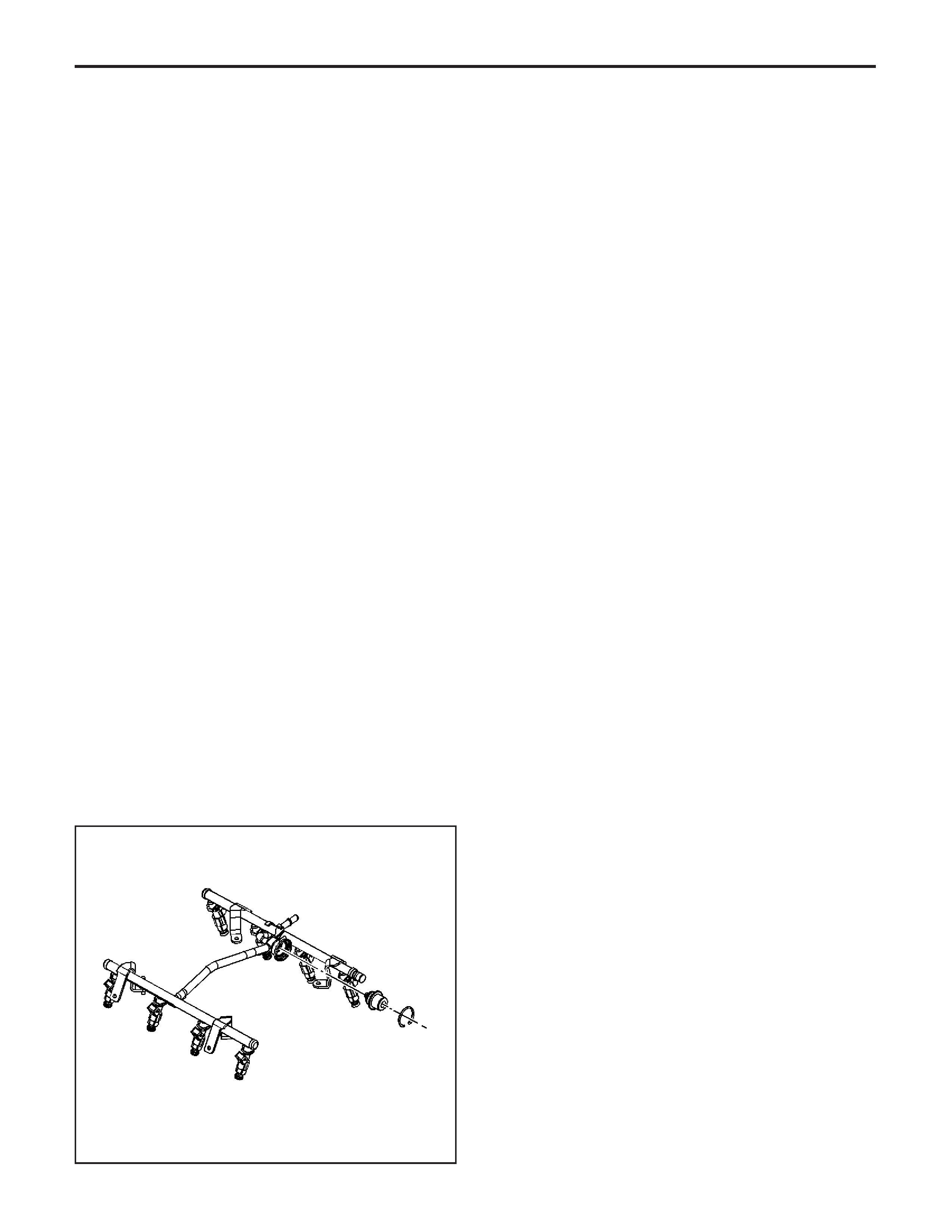
Fuel Pulse Dampener Replacement
Tool Required
J 34730-1A
Fuel Pressure Gage
Removal Procedure
Caution: Refer to Battery Disconnect Caution in
Cautions and Notices.
1. Disconnect the negative battery cable.
2. Remove the left fuel rail cover.
3. Relieve the fuel system pressure. Refer to
Fuel
Pressure Relief Procedure
.
4. Clean any dirt from the fuel pulse dampener
retaining ring.
5. Remove the fuel pulse dampener retaining ring.
6. Remove the fuel pulse dampener from the fuel rail.
217098
EngineControls-6.0LEngine
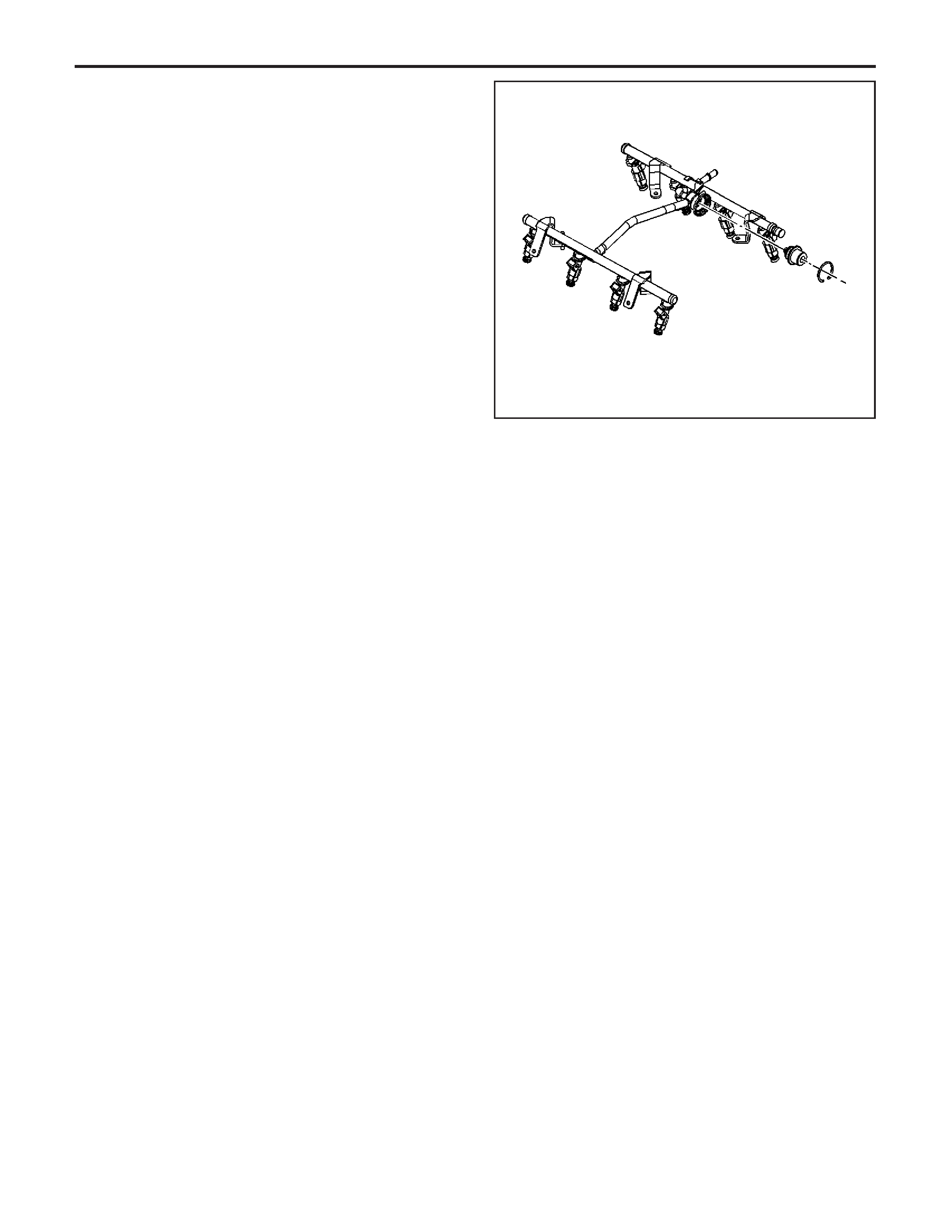
Installation Procedure
1. Install the new O-ring on the fuel pulse dampener.
2. Lubricate the fuel pulse dampener O-ring with
clean engine oil.
3. Push the fuel pulse dampener into the fuel rail.
4. Install the new fuel pulse dampener retaining ring.
5. Tighten the fuel filler cap.
6. Connect the negative battery cable.
7. Inspect for leaks.
7.1. Turn the ignition switch ON for 2 seconds.
7.2. Turn the ignition switch OFF for
10 seconds.
7.3. Turn the ignition switch ON.
7.4. Inspect for fuel leaks.
8. Install the left fuel rail cover.
9. Program the transmitters. Refer to
Transmitter
Programming (Domestic)
or
Transmitter
Programming (Export - Including Canada)
in
Keyless Entry.
217098
EngineEngineControls-6.0L

Fuel Hose/Pipes Replacement - Engine
Compartment
Tools Required
•
J 34730-1A
Fuel Pressure Gage
•
J 37088-A
Tool Set, Fuel Line Quick-Connect
Separator
Removal Procedure
Caution: Refer to Battery Disconnect Caution in
Cautions and Notices.
Notice:
• Do not repair the fuel feed or return pipes.
• Replace the fuel feed and return pipes with original
equipment or with parts that meet the GM
specifications for those parts. The replacement
pipe must have the same type of fittings as
the original pipe in order to ensure the integrity of
the connection.
1. Disconnect the negative battery cable. Refer to
Battery Negative Cable Disconnect/Connect
Procedure
in Engine Electrical.
2. Remove the left fuel rail cover.
3. Relieve the fuel system pressure. Refer to the
Fuel Pressure Relief Procedure
.
EngineEngineControls-6.0L
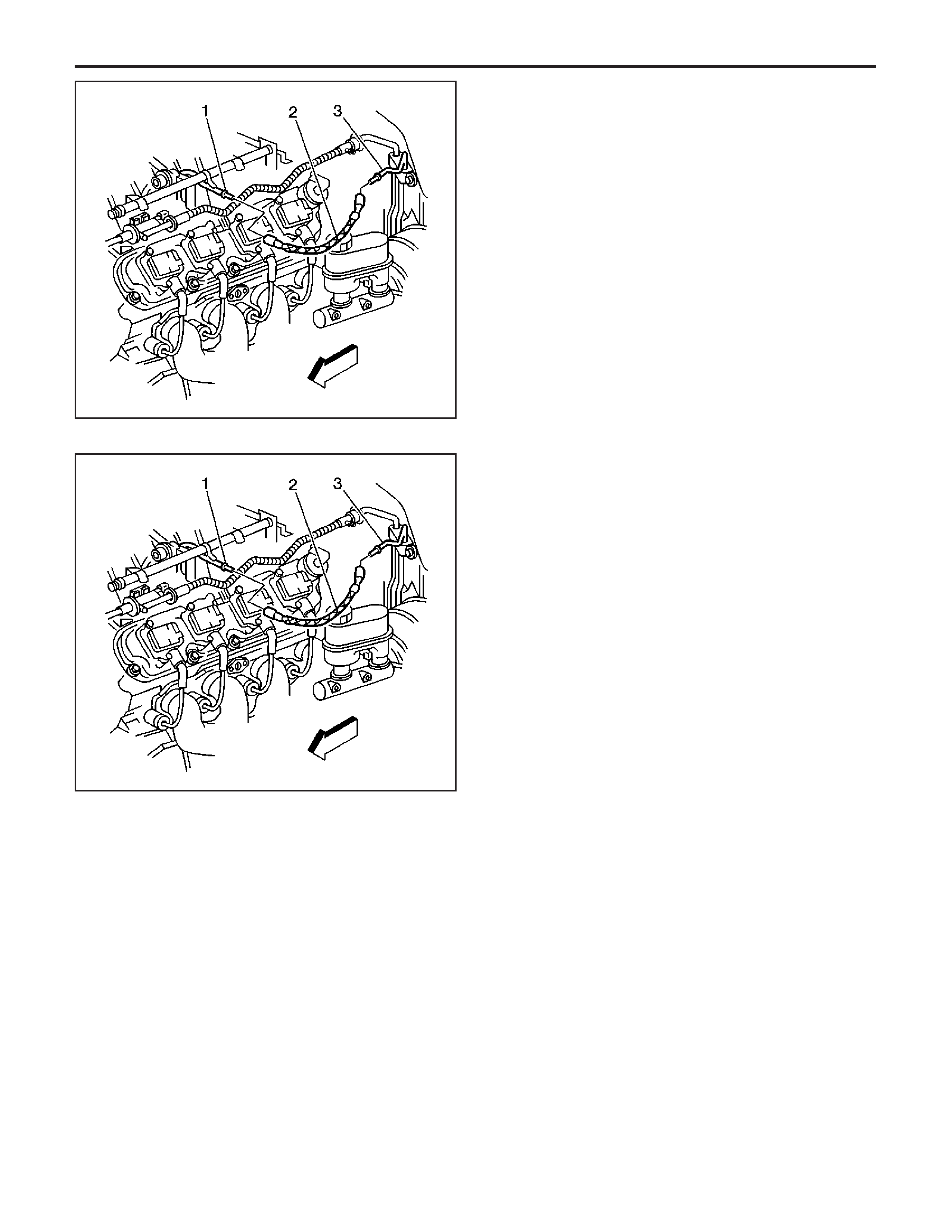
4. Disconnect the quick-connect fitting at the fuel
rail (1). Refer to
Quick Connect Fitting(s) Service
(Metal Collar)
.
5. Disconnect the quick-connect fitting at the chassis
fuel pipe (3). Refer to
Quick Connect Fitting(s)
Service (Metal Collar)
.
6. Remove the fuel feed hose (2).
7. Cap the chassis fuel pipe and the fuel rail pipe in
order to prevent possible fuel system
contamination.
8. Inspect the hose for bends, for kinks, for chafing,
and for cracks. Replace the hose as required.
Installation Procedure
1. Remove the caps from the chassis fuel pipe and
the fuel rail pipe.
2. Connect the fuel feed hose (2) to the chassis fuel
pipe (3). Refer to
Quick Connect Fitting(s) Service
(Metal Collar)
.
3. Connect the fuel feed hose (2) to the fuel rail (1).
Refer to
Quick Connect Fitting(s) Service (Metal
Collar)
.
4. Tighten the fuel filler cap.
5. Connect the negative battery cable. Refer to
Battery Negative Cable Disconnect/Connect
Procedure
in Engine Electrical.
6. Perform the following procedure in order to
inspect for leaks:
6.1. Turn the ignition switch ON for 2 seconds.
6.2. Turn the ignition switch OFF for
10 seconds.
6.3. Turn the ignition switch ON.
6.4. Inspect for fuel leaks.
7. Install the left fuel rail cover.
8. Program the transmitters. Refer to
Transmitter
Programming (Domestic)
or
Transmitter
Programming (Export - Including Canada)
in
Keyless Entry.
329571
329571
EngineControls-6.0LEngine

Fuel System Cleaning
Tools Required
•
J 34730-1A
Fuel Pressure Gage
•
J 37088-A
Tool Set, Fuel Line Quick Connect
Separator
Caution: Refer to Battery Disconnect Caution in
Cautions and Notices.
1. Disconnect the negative battery cable. Refer to
Battery Negative Cable Disconnect/Connect
Procedure
in Engine Electrical.
2. Relieve the fuel system pressure. Refer to the
Fuel Pressure Relief Procedure
.
3. Drain the fuel tanks. Refer to
Fuel Tank Draining
Procedure
.
4.Removethefueltank.
5.Removethefuelsenderassemblie.
6. Inspect the left fuel sender strainer. Replace a
contaminated strainer for the left fuel sender
only, and inspect the fuel pump.
7. Inspect the left fuel sender fuel pump inlet for
debris. Replace the left fuel sender assembly if
you find debris in the fuel pump inlet.
8. Inspect the right fuel sender strainers. Replace
the right fuel sender assembly if you find a
contaminated strainer. The right fuel sender
strainers are not serviced separately.
Important: When flushing the fuel tanks, handle the
fuel and water mixture as a hazardous material.
Handle the fuel and water mixture in accordance with
all applicable local, state, and federal laws and
regulations.
9. Flush the fuel tanks with hot water.
10. Pour the water out of the fuel sender assembly
openings. Rock the tanks to be sure that removal
of the water from the tanks is complete.
11. Install the fuel sender assemblies. Refer to
Fuel
Sender Assembly Replacement (Right )
or
Fuel
Sender Assembly Replacement (Left)
.
12.Installthefueltank.
13. Refill the fuel system.
14. Install the fuel filler cap.
15. Connect the negative battery cable. Refer to
Battery Negative Cable Disconnect/Connect
Procedure
in Engine Electrical.
16. Perform the following procedure in order to
inspect for leaks:
16.1. Turn the ignition switch ON for 2 seconds.
16.2. Turn the ignition switch OFF for
10 seconds.
16.3. Turn the ignition switch ON.
16.4. Inspect for fuel leaks.
17. Program the transmitters. Refer to
Transmitter
Programming (Domestic)
or
Transmitter
Programming (Export - Including Canada)
in
Keyless Entry.
EngineEngineControls-6.0L
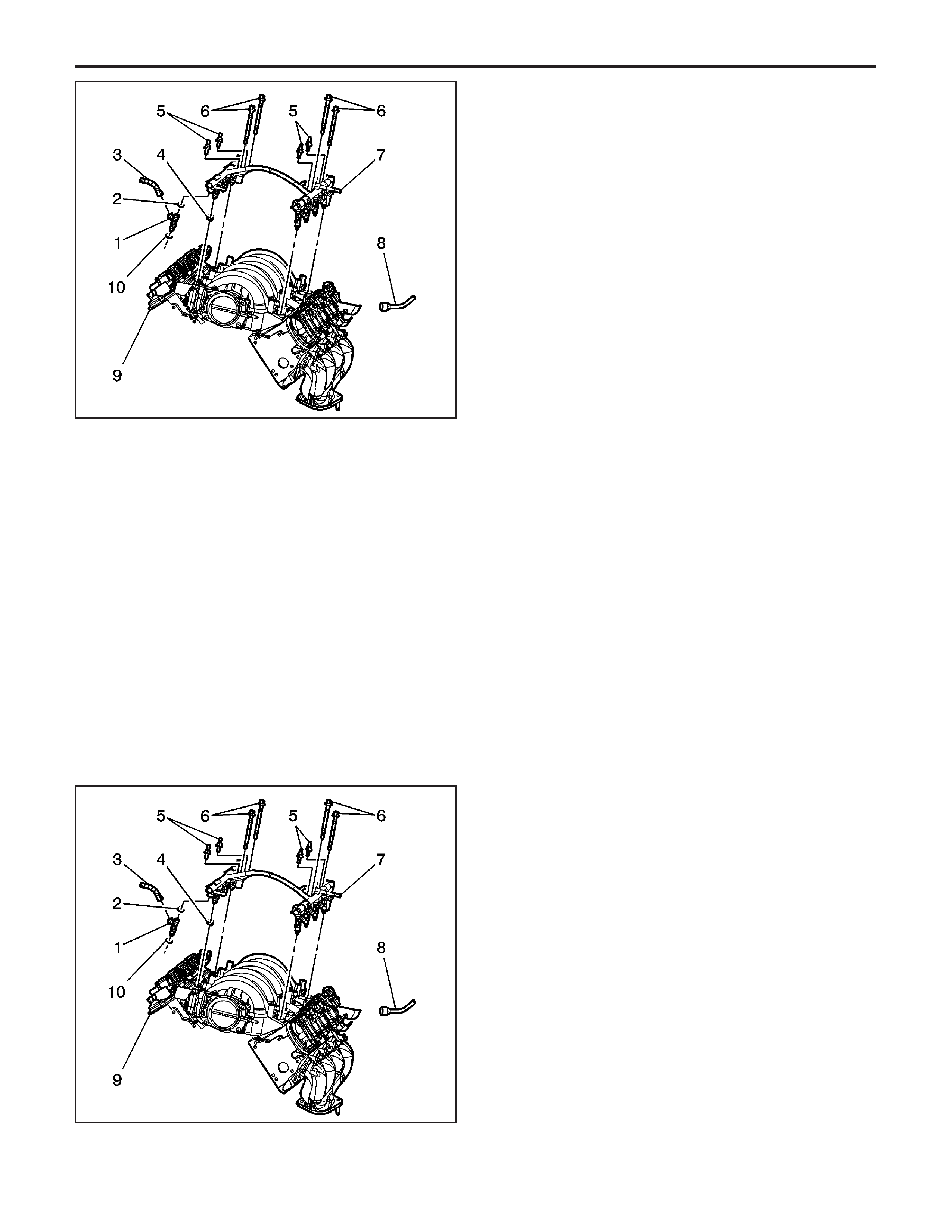
Fuel Rail Assembly Replacement
Tools Required
•
J 34730-1A
Fuel Pressure Gage
•
J 37088-A
Tool Set, Fuel Line Quick Connect
Separator
Removal Procedure
Caution: Refer to Battery Disconnect Caution in
Cautions and Notices.
1. Disconnect the negative battery cable. Refer to
Battery Negative Cable Disconnect/Connect
Procedure
in Engine Electrical.
2. Remove the engine sight covers. Refer to
Engine
Sight Shield Replacement
in Engine Mechanical –
6.0L.
3. Relieve the fuel system pressure. Refer to
Fuel
Pressure Relief Procedure
.
4. Using compressed air, clean the fuel injector and
intake manifold.
5. Disconnect the fuel feed line (1) from the fuel
rail (2).
Important: Before disconnecting the electrical
connectors, mark the relationship of the electrical
connector to the fuel rail injector fitting. This will ensure
the proper electrical connector sequence for
reassembly.
6. Mark the fuel injector to the electrical connector.
Disconnect the electrical connectors.
7. Remove the intake manifold bolts (3).
8. Remove the mounting bolts for the fuel rail (4).
9. Remove the fuel rail assembly (2) from the intake
manifold (10).
10. Remove the fuel injectors (7) from the fuel rail.
Refer to
Fuel Injector Replacement
.
Installation Procedure
Important: When installing the fuel injectors, apply a
small amount of clean motor oil to the O-rings.
1. Install the fuel injectors (7) in the fuel rail (2).
Refer to
Fuel Injector Replacement
.
2. Install the fuel rail (2) to the intake manifold (10).
3. Apply a 5 mm (0.020 in) band of
GM P/N 12345382 (Canadian P/N 10953489)
threadlock or equivalent to the threads of the fuel
rail and intake manifold bolts.
Caution:Thefuelrail
stop bracket must be installed onto the engine
assembly. The stop bracket serves as a protective
shield for the fuel rail in the event of a vehicle
frontal crash. If the fuel rail stop bracket is
not installed and the vehicle is involved in a frontal
crash, fuel could be sprayed possibly causing a
fire and personal injury from burns.
Notice:
Refer to
Fastener Notice
in Cautions and
Notices.
1467502
1467502
EngineControls-6.0LEngine
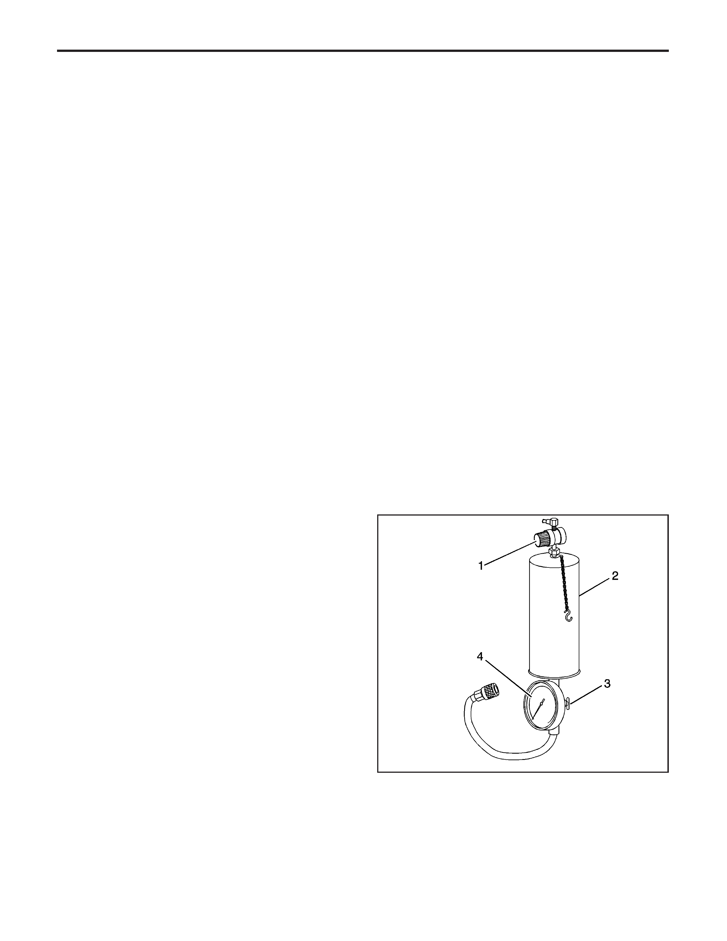
4. Install the intake mounting bolts (3).
Tighten
Tighten the intake manifold bolts to
10 N·m (89 lb in).
5. Install the fuel rail (4) mounting bolts.
Tighten
Tighten the intake manifold bolts to
10 N·m (89 lb in).
Important: Ensure that the electrical connectors are
attached to the proper fuel injector.
6. Reconnect the electrical connectors (5) for the
fuel injectors (7).
7. Reconnect the fuel feed hose (1) to the fuel
rail (2).
8. Reconnect the negative battery cable.
9. Perform the following procedure in order to
inspect for leaks:
9.1. Turn the ignition switch ON for 2 seconds.
9.2. Turn the ignition switch OFF for
10 seconds.
9.3. Turn the ignition switch ON.
9.4. Inspect for fuel leaks.
10. Install the engine sight covers. Refer to
Engine
Sight Shield Replacement
in Engine Mechanical
– 6.0L.
11. Program the transmitters. Refer to
Transmitter
Programming (Domestic)
or
Transmitter
Programming (Export - Including Canada)
in
Keyless Entry.
Fuel Injector Cleaning Procedure
Tools Required
•
J 37287
Fuel Line Shut-Off Adapters
•
J 35800-A
Fuel Injector Cleaner
•
J 42873-1
3/8 Fuel Line Shut-Off Valve
•
J 42873-2
5/16 Return Pipe Shut-Off Valve
•
J 42964-1
3/8 Fuel Pipe Shut-Off Valve
•
J 42964-2
5/16 Fuel Pipe Shut-Off Valve
Notice:
• GM Top-Engine Cleaner is the only injector
cleaning agent recommended. Do not use other
cleaning agents, as they may contain methanol
which can damage fuel system components.
• Under NO circumstances should the top engine
cleaner be added to the vehicles fuel tank, as
it may damage the fuel pump and other system
components.
• Do not exceed a 10 percent cleaning solution
concentration. Higher concentrations may damage
fuel system components. Testing has
demonstrated that exceeding the 10 percent
cleaning solution concentration does not improve
the effectiveness of this procedure.
651337
EngineEngineControls-6.0L

Important: Vehicles with less than 160 km (100 mi)
on the odometer should not have the injectors cleaned.
These vehicles should have the injectors replaced.
Important: During this procedure you will need a total
of 960 ml (32.4 oz) of cleaning solution. That is
2 tanks of solution for the
J 35800-A
. Other brands of
tools may have a different capacity and would
therefore require more or less tanks to complete the
procedure. You must use all 960 ml (32.4 oz) of
solution to ensure complete injector cleaning.
1. Obtain
J 35800-A
(2).
Important: Make sure the valve at the bottom of the
canister (3) is closed.
2. For US dealers, empty 2 pre-measured GM
Top-Engine Cleaner containers, 24 ml (0.812 oz)
each, GM P/N 12346535, into the
J 35800-A
.
3. For Canadian dealers, measure and dispense
48 ml (1.62 oz) of Top-Engine Cleaner,
Canadian P/N 992872, into the
J 35800-A
.
4. If you are using any other brand of tank you will
need a total of 96 ml (3.24 oz) of Top-Engine
Cleaner mixed with 864 ml (29.16 oz) of regular
unleaded gasoline.
5. Fill the injector cleaning tank with regular unleaded
gasoline. Be sure to follow all additional
instructions provided with the tool.
6. Electrically disable the vehicle fuel pump by
removing the fuel pump relay and disconnecting
the oil pressure switch connector, if equipped.
7. Disconnect the fuel feed and return line, if
equipped, at the fuel rail. Plug the fuel feed
and return line, if equipped, coming off the fuel rail
with
J 37287
,or
J 42964-1
, and
J 42964-2
or
J 42873-1
, and
J 42873-2
as appropriate for the
fuel system.
8. Connect the
J 35800-A
to the vehicle fuel rail.
9. Pressurize the
J 35800-A
to 510 kPa (75 psi).
10. Start and idle the engine until it stalls due to lack
of fuel. This should take approximately 15–
20 minutes.
11. Disconnect
J 35800-A
from the fuel rail.
12. Reconnect the vehicle fuel pump relay and oil
pressure switch connector, if equipped.
13. Remove
J 37287
or
J 42964-1
, and
J 42964-2
or
J 42873-1
, and
J 42873-2
and reconnect the
vehicle fuel feed and return lines.
14. Start and idle the vehicle for an additional
2 minutes to ensure residual injector cleaner
is flushed from the fuel rail and fuel lines.
15. Repeat steps 1–5 of the Injector Balance Test,
and record the fuel pressure drop from each
injector.
16. Subtract the lowest fuel pressure drop from the
highest fuel pressure drop. If the value is
15 kPa (2 psi) or less, no additional action is
required. If the value is greater than 15 kPa (2 psi),
replace the injector with the lowest fuel
pressure drop.
EngineControls-6.0LEngine
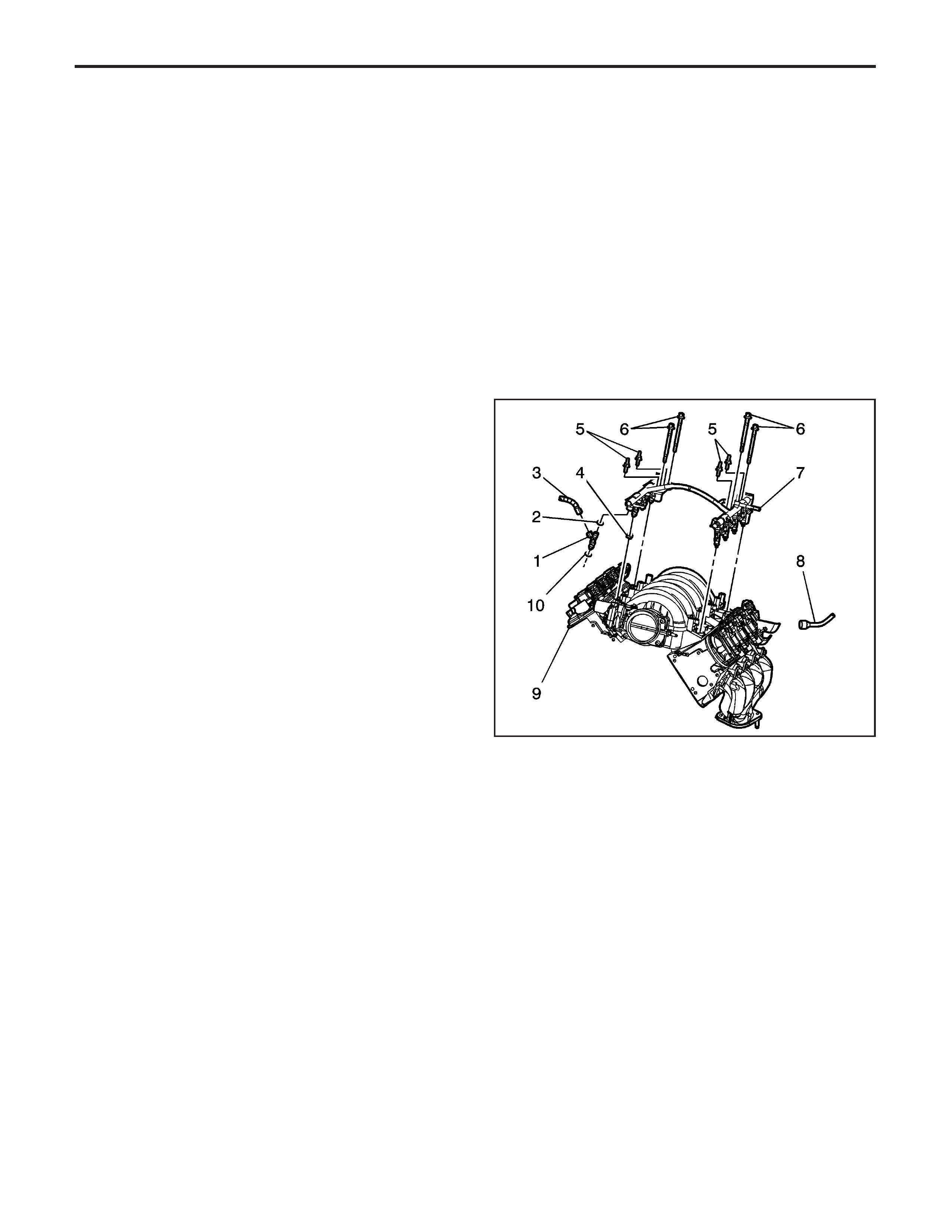
17. Add one ounce of Port Fuel Injector Cleaner,
GM P/N 12345104 (Canadian P/N 10953467),
to the vehicle fuel tank for each gallon of gasoline
estimated to be in the fuel tank. Instruct the
customer to add the reminder of the bottle of Port
Fuel Injector Cleaner to the vehicle fuel tank at
the next fill-up.
18. Advise the customer to change brands of fuel and
to add GM Port Fuel Injector Cleaner every
5 000 km (3,000 mi). GM Port Fuel Injector
Cleaner contains the same additives that the fuel
companies are removing from the fuel to
reduce costs. Regular use of GM Port Fuel
Injector Cleaner should keep the customer from
having to repeat the injector cleaning procedure.
19. Road test the vehicle to verify that the customer
concern has been corrected.
Fuel Injector Replacement
Tools Required
•
J 34730-1A
Fuel Pressure Gage
•
J 37088-A
Tool Set, Fuel Line Quick Connect
Separator
Removal Procedure
1. Remove the fuel rail assembly. Refer to
Fuel Rail
Assembly Replacement
.
2. Disconnect the electrical connector (5) for the fuel
injector (7).
3. Remove the retaining clip (6) for the fuel
injector (7).
Notice:
Usecarein
removing the fuel injectors in order to prevent damage
to the fuel injector electrical connector pins or the
fuel injector nozzles. Do not immerse the fuel injector
in any type of cleaner. The fuel injector is an
electrical component and may be damaged by this
cleaning method.
4. Remove the fuel injector (7) from the fuel rail (2).
1467502
EngineEngineControls-6.0L
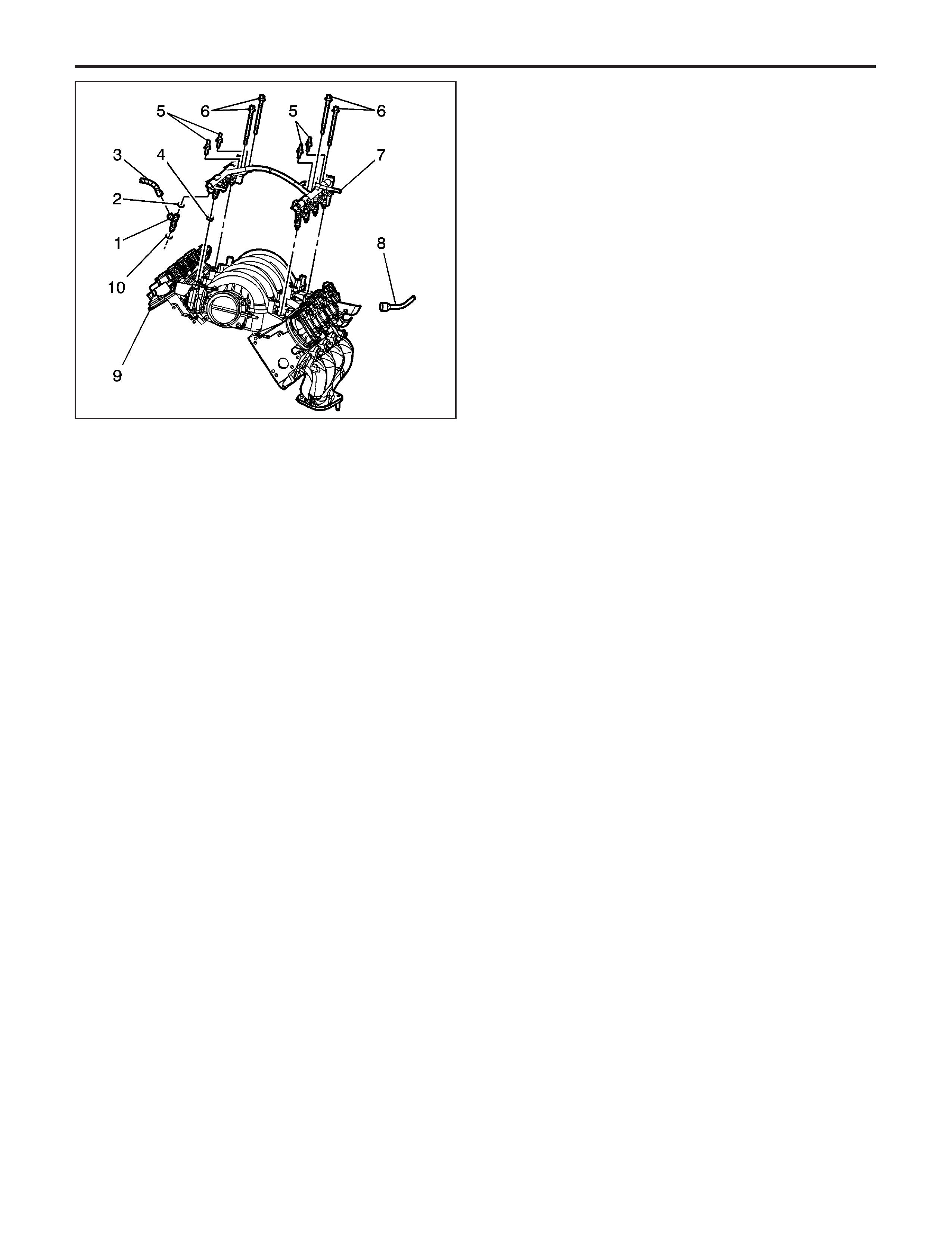
Installation Procedure
Important: If the fuel injectors are being removed for
the replacement of the fuel rail, it is not necessary
to replace the O-rings on the fuel injector. Replace the
O-rings only if they are damage.
1. Apply a small amount of clean motor oil to the
O-rings (8) and (9), before installing the new
fuel injector.
2. Install the fuel injector (7) in the fuel rail (2).
3. Install the retaining clips for the fuel injector (6).
4. Reconnect the electrical connector (50 for the fuel
injector (7).
5. Install the fuel rail assembly (2). Refer to
Fuel Rail
Assembly Replacement
.
6. Inspect for leaks:
6.1. Turn the ignition switch ON for 2 seconds.
6.2. Turn the ignition switch OFF for
10 seconds.
6.3. Turn the ignition switch ON.
6.4. Inspect for fuel leaks.
Evaporative Emission (EVAP) Canister
Purge Solenoid Valve Replacement
Removal Procedure
1. Remove the left fuel rail cover.
1467502
EngineControls-6.0LEngine
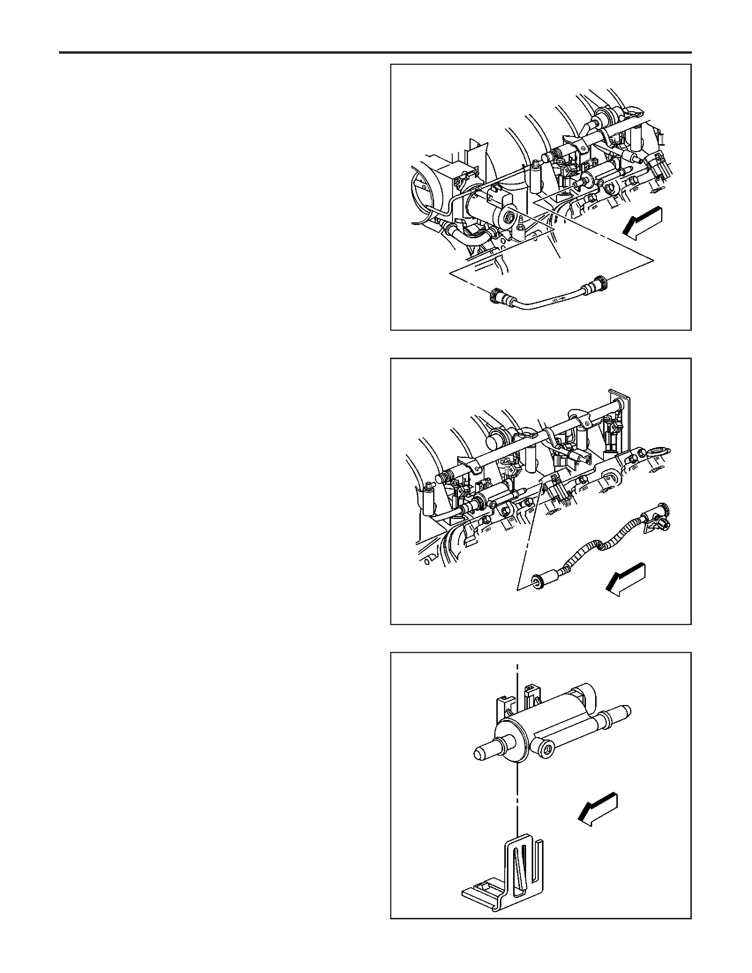
2. Disconnect the engine vacuum pipe from the
EVAP canister purge solenoid valve to intake
manifold EVAP pipe.
3. Disconnect the engine purge pipe from the EVAP
canister purge valve.
4. Disconnect the EVAP canister purge valve
harness connector.
5. Remove the EVAP canister purge valve from the
purge bracket.
419425
406071
419407
EngineEngineControls-6.0L
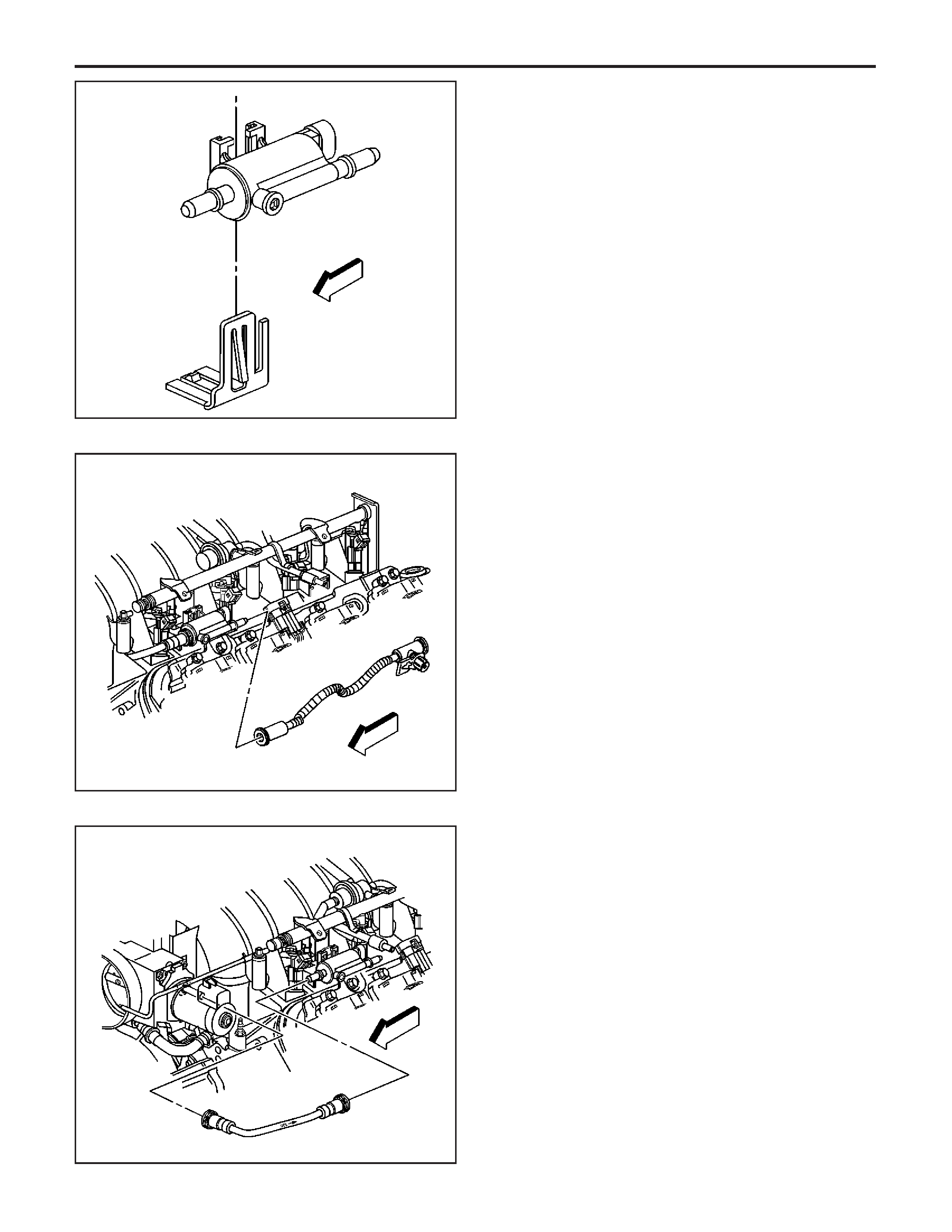
Installation Procedure
1. Install the EVAP canister purge valve to the purge
bracket.
2. Connect the harness connector to the EVAP
canister purge valve.
3. Connect the engine purge pipe to the chassis
purge pipe.
4. Connect the engine vacuum pipe to the EVAP
canister purge valve.
419407
406071
419425
EngineControls-6.0LEngine
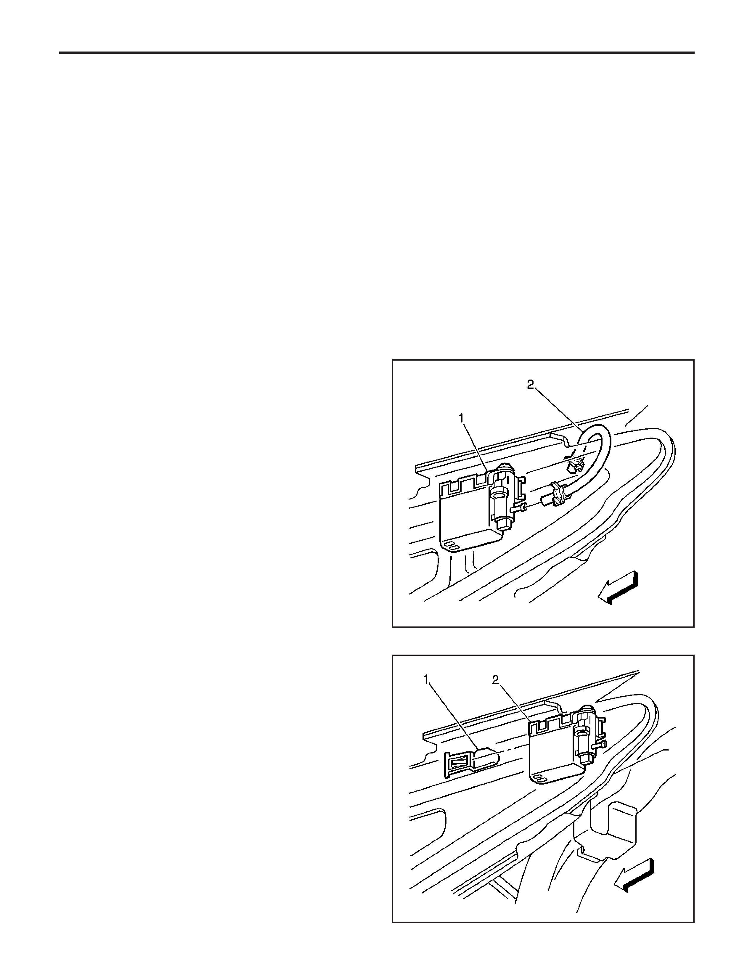
5. Install the left fuel rail cover.
Evaporative Emission (EVAP) Canister
Vent Solenoid Valve Replacement
Removal Procedure
1. Raise the vehicle. Refer to
Lifting and Jacking the
Vehicle
in General Information.
2. Lower the right muffler for automatic transmission
equipped vehicles only. Refer to
Muffler
Replacement - Right
in Engine Exhaust.
3. Disconnect the EVAP canister valve harness
connector.
4. Disconnect the vent hose (2) from the EVAP
canister vent valve (1).
5. Remove the EVAP canister vent valve (2) from
the vent bracket (1).
561130
329567
EngineEngineControls-6.0L
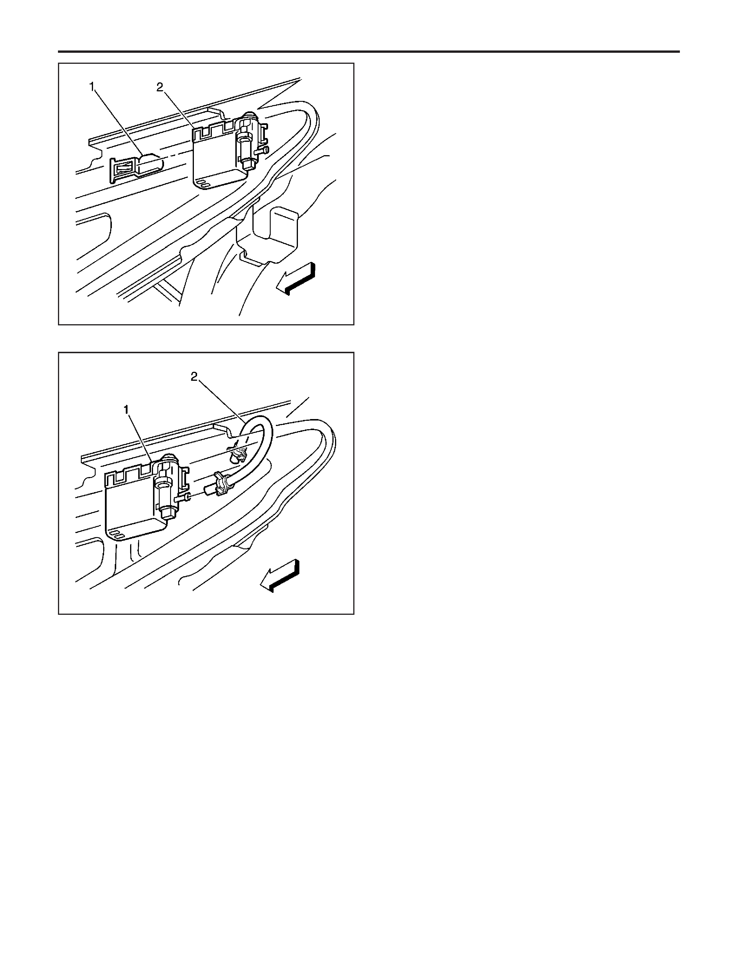
Installation Procedure
1. Install the EVAP canister vent valve (2) to the
vent bracket (1).
2. Connect the vent hose (2) to the EVAP canister
vent valve (1).
3. Connect the EVAP vent valve electrical connector.
4. For automatic transmission– equipped vehicles
only, raise the right muffler. Refer to
Muffler
Replacement - Right
in Engine Exhaust.
5. Lower the vehicle.
Evaporative Emission (EVAP) System
Hoses/Pipes Replacement (Vacuum
Supply)
Removal Procedure
Caution: Refer to Fuel and EVAP Pipe Caution in
Cautions and Notices.
1.Removetheenginecover.
329567
561130
EngineControls-6.0LEngine
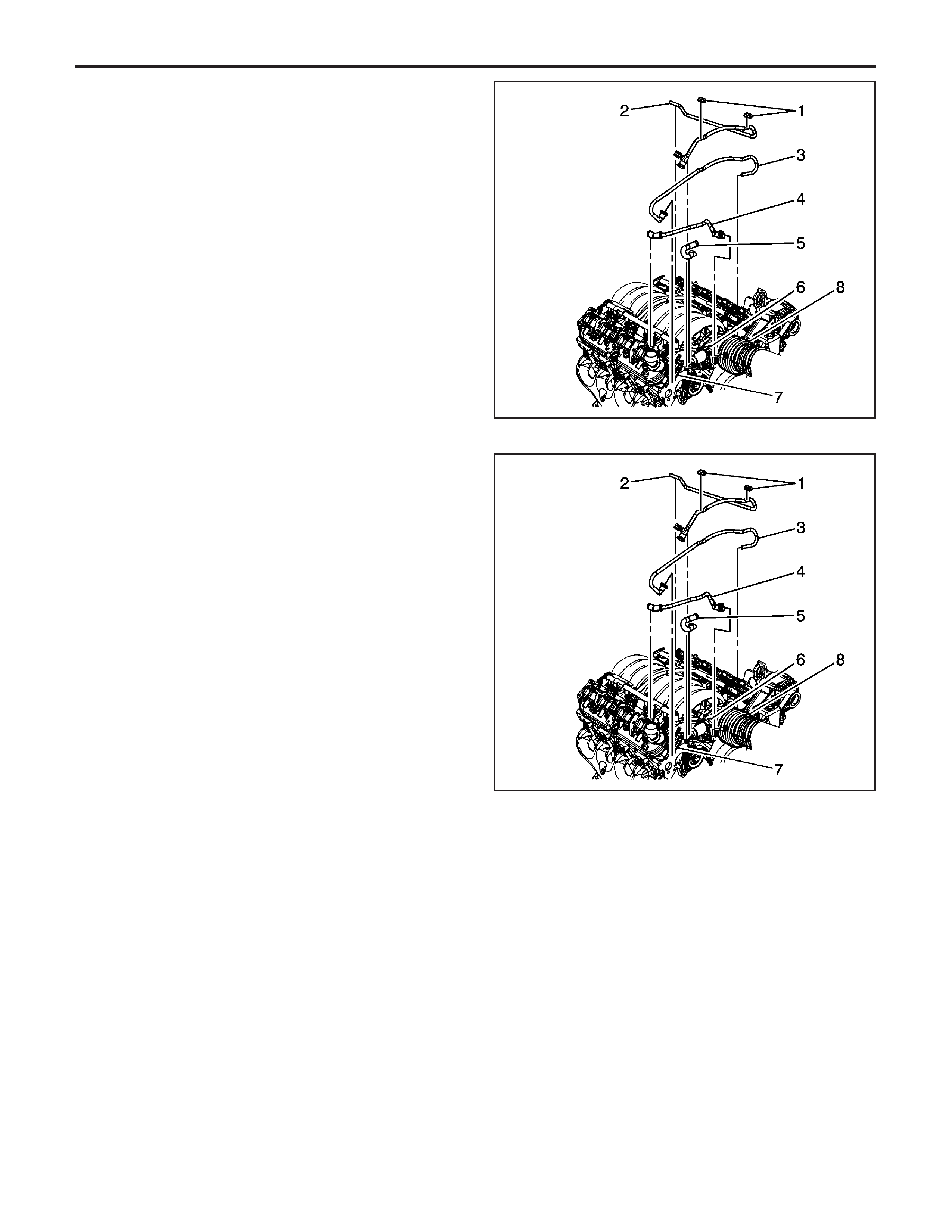
2. Disconnect the quick-connect fittings at the
throttle body (6) and the evaporative
emission (EVAP) canister purge valve (7). Refer
to
Quick Connect Fitting(s) Service (Plastic
Collar)
.
3. Remove the EVAP pipe (3).
Installation Procedure
1. Reconnect the EVAP pipe (3) to the throttle
body (6).
2. Reconnect the EVAP pipe (3) to EVAP canister
purge valve (7).
3.Installtheenginecover.
1481776
1481776
EngineEngineControls-6.0L
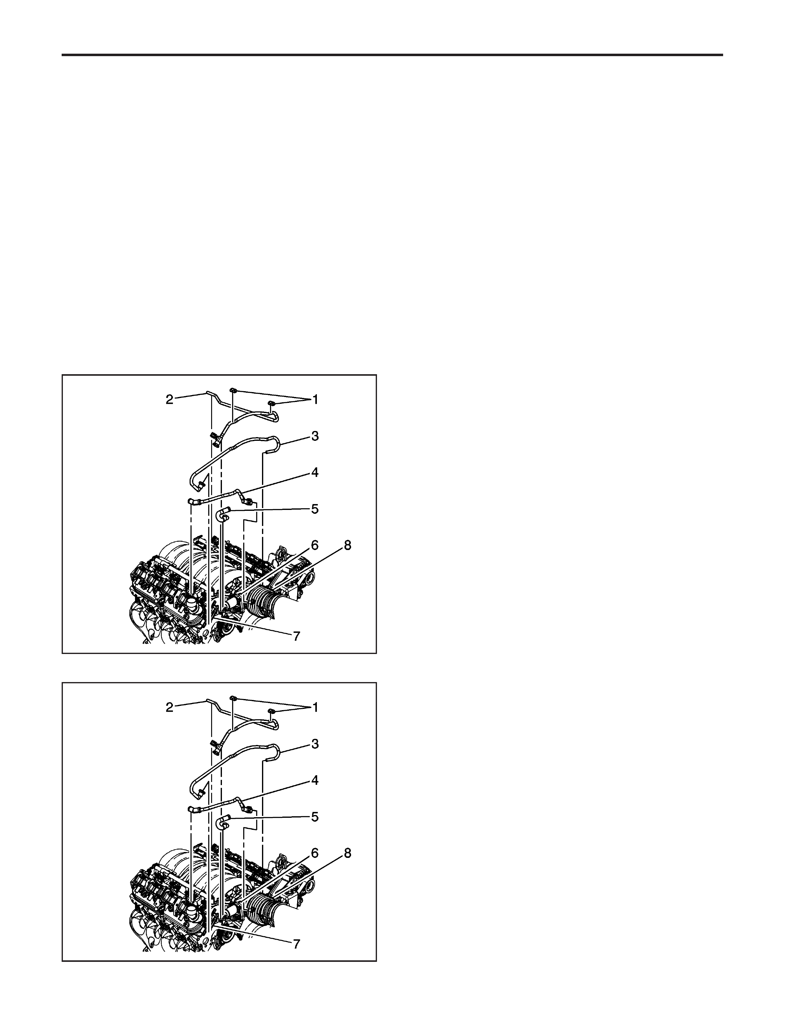
Evaporative Emission (EVAP) System
Hoses/Pipes Replacement (Engine
Purge Pipe)
Removal Procedure
Caution: Refer to Fuel and EVAP Pipe Caution in
Cautions and Notices.
1. Remove the left engine sight cover.
2. Disconnect the quick-connect fittings at the
evaporative emission (EVAP) canister purge
valve (7). Refer to
Quick Connect Fitting(s)
Service (Plastic Collar)
.
3. Remove the EVAP pipe (2).
Installation Procedure
1. Install the EVAP pipe (2) to the EVAP canister
purge valve (7).
2. Connect the EVAP pipe (2) to the connection for
the canister at the left rear of the engine.
1481776
1481776
EngineControls-6.0LEngine

3.Installtheenginecover.
Evaporative Emission (EVAP) Hoses/Pipes
Replacement - Engine (Chassis)
For information on replacement of EVAP hoses
refer to Holden VZ Service Information
EngineEngineControls-6.0L

Spark Plug Wire Inspection
Spark plug wire integrity is vital for proper engine
operation. A thorough inspection will be necessary to
accurately identify conditions that may affect engine
operation. Inspect for the following conditions:
1. Correct routing of the spark plug wires. Incorrect
routing may cause cross-firing.
2. Any signs of cracks or splits in the wires.
3. Inspect each boot for the following conditions:
• Tearing
• Piercing
• Arcing
• Carbon tracking
• Corroded terminal
If corrosion, carbon tracking, or arcing are indicated
on a spark plug wire boot or on a terminal, replace the
wire and the component connected to the wire.
EngineEngineControls-6.0L
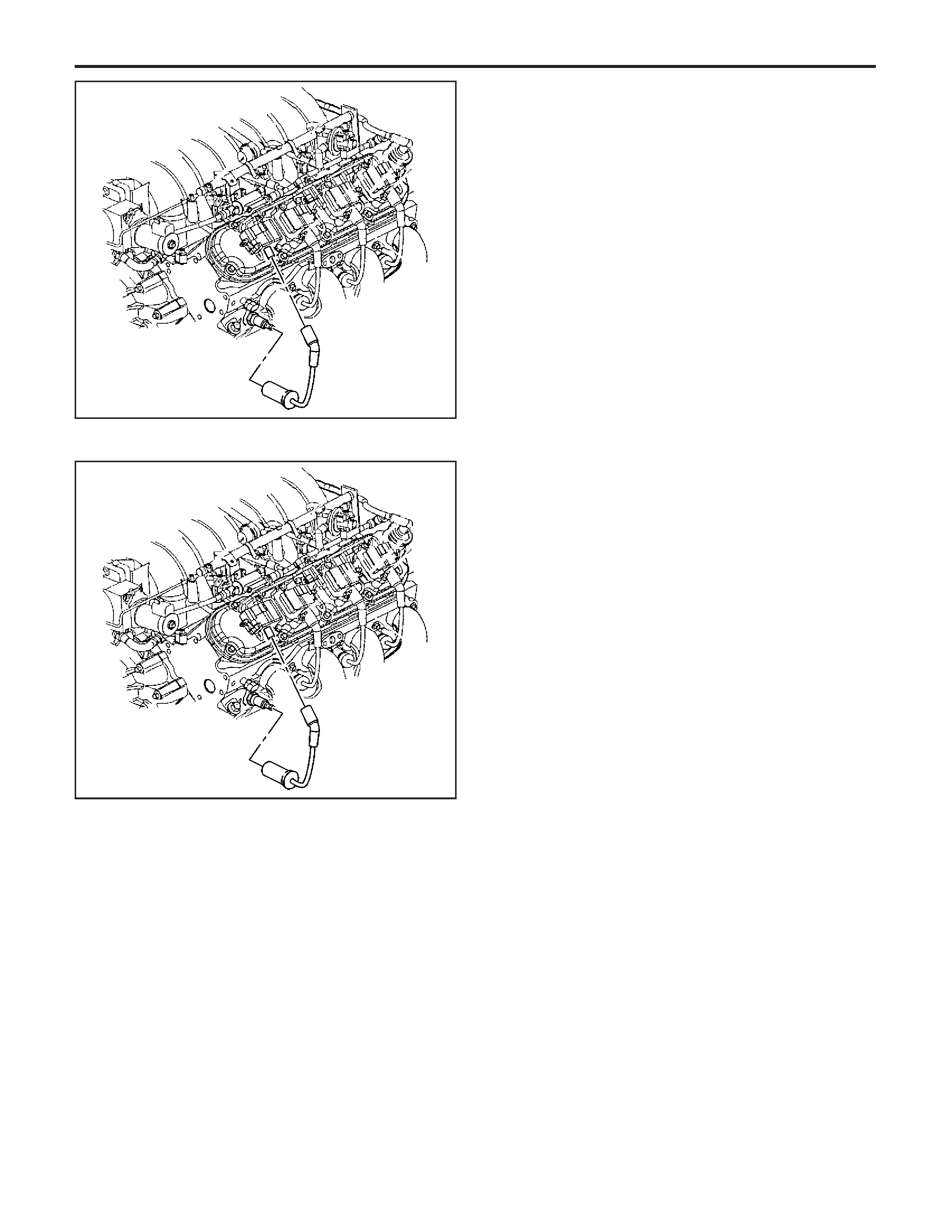
Spark Plug Wire Replacement
Removal Procedure
1. Disconnect the spark plug wires at each
spark plug:
• Twist each spark plug boot 1/2 turn.
• Pull only on the boot in order to remove the
wire from each spark plug.
2. Disconnect the spark plug wires from the
ignition coil:
• Twist each spark plug boot 1/2 turn.
• Pull only on the boot in order to remove the
wires from the ignition coil.
Installation Procedure
1. Install the spark plug wires at the ignition coil.
2. Install the spark plug wire to each spark plug.
3. Inspect the wires for proper installation:
• Push sideways on each boot in order to inspect
the seating.
• Reinstall any loose boot.
74069
74069
EngineControls-6.0LEngine
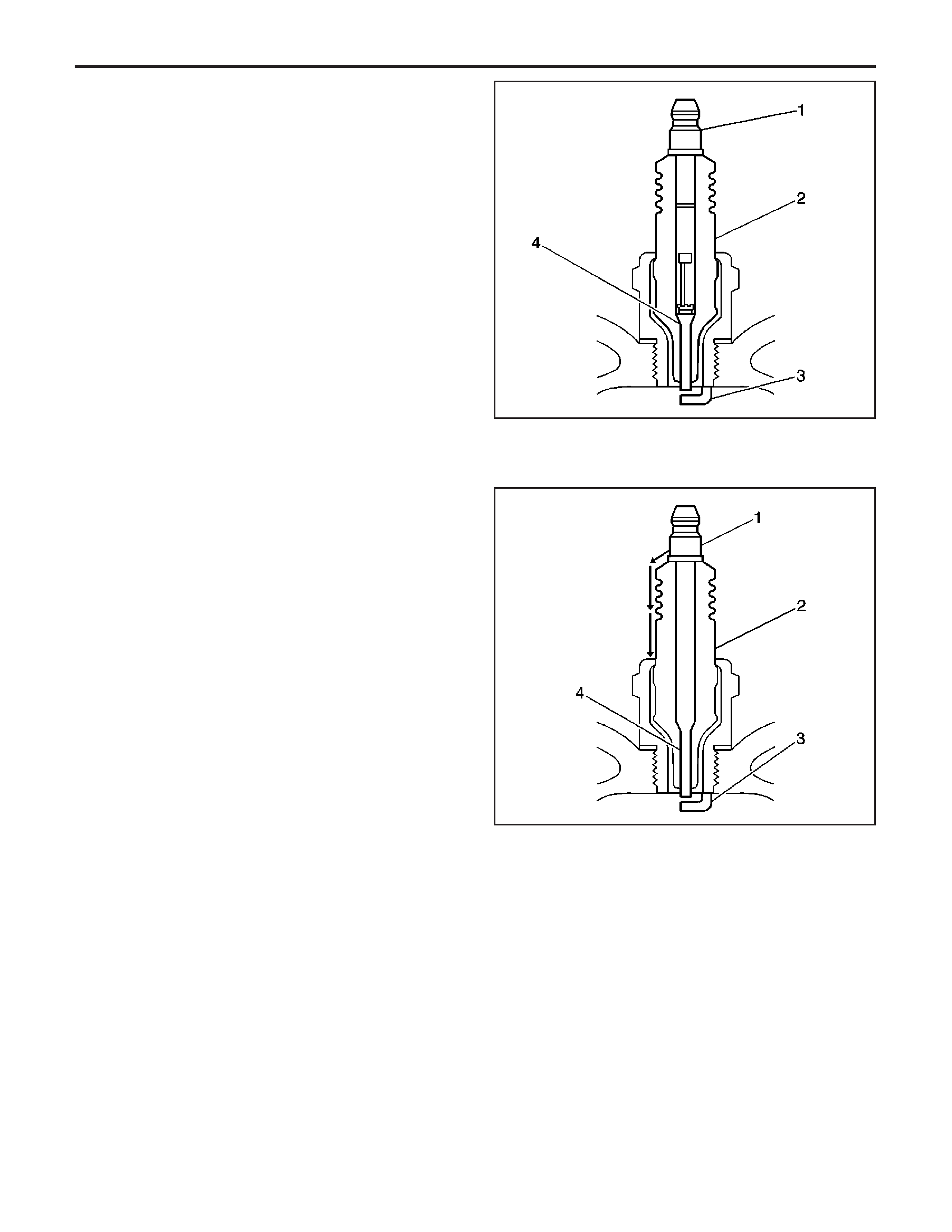
Spark Plug Inspection
Spark Plug Usage
• Verify that the correct spark plug is installed. An
incorrect spark plug causes driveability conditions.
Refer to
Ignition System Specifications
for the
correct spark plug.
• Ensure that the spark plug has the correct heat
range. An incorrect heat range causes the
following conditions:
− Spark plug fouling — colder plug
− Pre-ignition causing spark plug and/or engine
damage — hotter plug
Spark Plug Inspection
• Inspect the terminal post (1) for damage.
− Inspect for a bent or broken terminal post (1).
− Test for a loose terminal post (1) by
twisting and pulling the post. The
terminal post (1) should NOT move.
• Inspect the insulator (2) for flashover or carbon
tracking, soot. This is caused by the electrical
charge traveling across the insulator (2) between
the terminal post (1) and ground. Inspect for
the following conditions:
− Inspect the spark plug boot for damage.
− Inspect the spark plug recess area of
the cylinder head for moisture, such as oil,
coolant, or water. A spark plug boot that
is saturated causes arcing to ground.
622530
622529
EngineEngineControls-6.0L
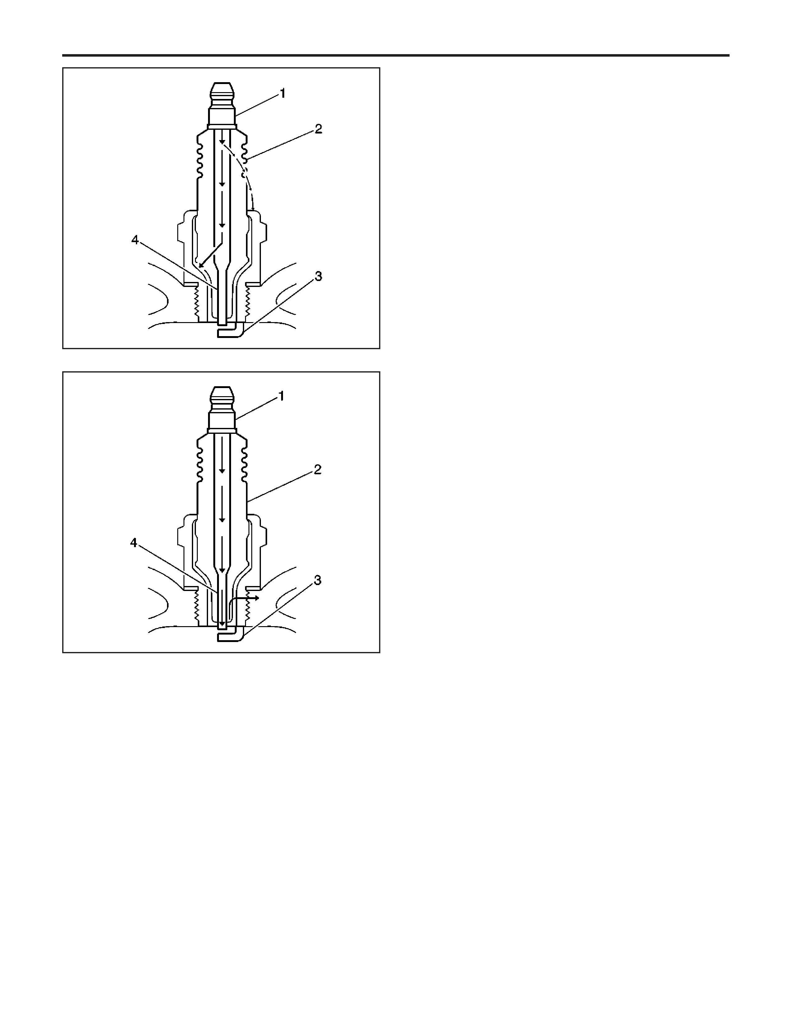
• Inspect the insulator (2) for cracks. All or part of
the electrical charge may arc through the crack
instead of the electrodes (3, 4).
• Inspect for evidence of improper arcing.
− Measure the gap between the center
electrode (4) and the side electrode (3)
terminals. Refer to
Ignition System
Specifications
. An excessively-wide electrode
gap can prevent correct spark plug
operation.
− Inspect for the correct spark plug torque.
Refer to
Ignition System Specifications
.
Insufficient torque can prevent correct spark
plug operation. An over-torqued spark
plug, causes the insulator (2) to crack.
− Inspect for signs of tracking that occurred
near the insulator tip instead of the center
electrode (4).
− Inspect for a broken or worn side
electrode (3).
− Inspect for a broken, worn, or loose center
electrode (4) by shaking the spark plug.
• A rattling sound indicates internal
damage.
• A loose center electrode (4) reduces the
spark intensity.
− Inspect for bridged electrodes (3, 4). Deposits
on the electrodes reduce or eliminates
the gap.
− Inspect for worn or missing platinum pads on
the electrodes (3, 4), if equipped.
− Inspect for excessive fouling.
• Inspect the spark plug recess area of the cylinder
head for debris. Dirty or damaged threads can
cause the spark plug not to seat correctly during
installation.
Spark Plug Visual Inspection
• Normal operation — Brown to grayish-tan with
small amounts of white powdery deposits are
normal combustion by-products from fuels
with additives.
622528
622527
EngineControls-6.0LEngine
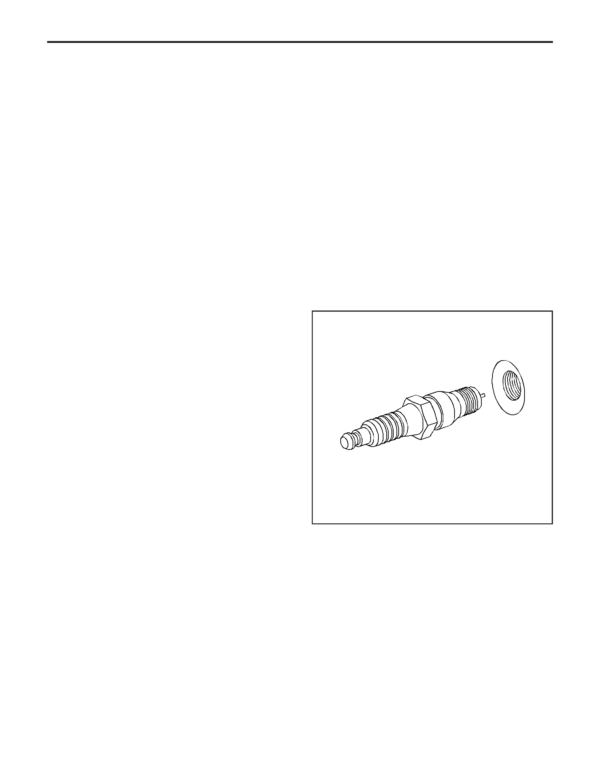
• Carbon Fouled — Dry, fluffy black carbon, or soot
caused by the following conditions:
− Rich fuel mixtures
• Leaking fuel injectors
• Excessive fuel pressure
• Restricted air filter element
• Incorrect combustion
− Reduced ignition system voltage output
• Weak coils
• Worn ignition wires
• Incorrect spark plug gap
− Excessive idling or slow speeds under light
loads can keep spark plug temperatures so
low that normal combustion deposits
may not burn off.
• Deposit Fouling — Oil, coolant, or additives that
include substances such as silicone, very white
coating, reduces the spark intensity. Most powdery
deposits will not effect spark intensity unless
they form into a glazing over the electrode.
Spark Plug Replacement
Removal Procedure
1. Remove the fuel rail covers.
Notice:
Allowthe
engine to cool before removing the spark plugs.
Attempting to remove the spark plugs from a hot
engine may cause the plug threads to seize, causing
damage to cylinder head threads.
Notice:
Cleanthe
spark plug recess area before removing the spark
plug. Failure to do so could result in engine damage
because of dirt or foreign material entering the cylinder
head, or by the contamination of the cylinder head
threads. The contaminated threads may prevent
the proper seating of the new plug. Use a thread
chaser to clean the threads of any contamination.
2. Remove the spark plug wires. Refer to
Spark Plug
Wire Replacement
.
3. Loosen each spark plug 1 or 2 turns.
4. Brush or use compressed air to remove any dirt
around the spark plugs.
5. Remove the spark plugs one at a time and place
each plug in a tray marked with the corresponding
cylinder numbers.
14824
EngineEngineControls-6.0L
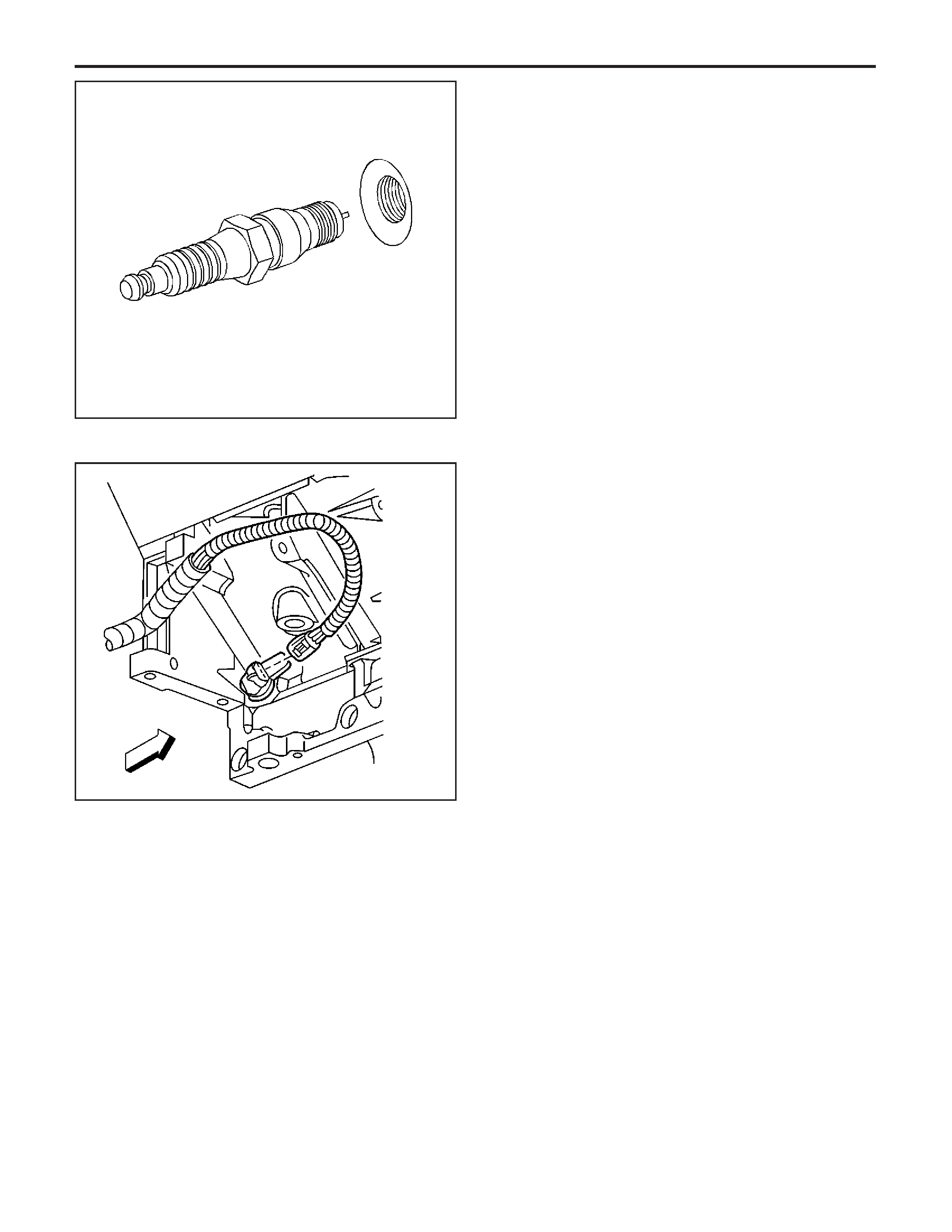
Installation Procedure
1. Inspect each spark plug gap. Adjust each plug as
needed.
Specification
Spark plug gap: 1.016 mm (0.040 in)
2. Hand start the spark plugs in the corresponding
cylinders.
Notice:
Refer to
Fastener Notice
in Cautions and
Notices.
3. Tighten the spark plugs.
Tighten
• For cylinder head-new: Tighten the spark plugs
to 20 N·m (15 lb ft).
• For cylinder head-all subsequent installations:
Tighten the spark plugs to 15 N·m (11 lb ft).
4. Install the spark plug wires. Refer to
Spark Plug
Wire Replacement
.
5. Install the fuel rail covers.
Crankshaft Position (CKP) Sensor
Replacement
Removal Procedure
Caution: Refer to Battery Disconnect Caution in
Cautions and Notices.
1. Disconnect the negative battery cable. Refer to
Battery Negative Cable Disconnect/Connect
Procedure
in Engine Electrical.
Caution: Refer to Vehicle Lifting Caution in
Cautions and Notices.
2. Raise the vehicle. Refer to
Lifting and Jacking the
Vehicle
in General Information.
3. Remove the starter. Refer to
Starter Motor
Replacement
in Engine Electrical.
4. Disconnect the crankshaft position (CKP) sensor
electrical connector.
14824
56592
EngineControls-6.0LEngine
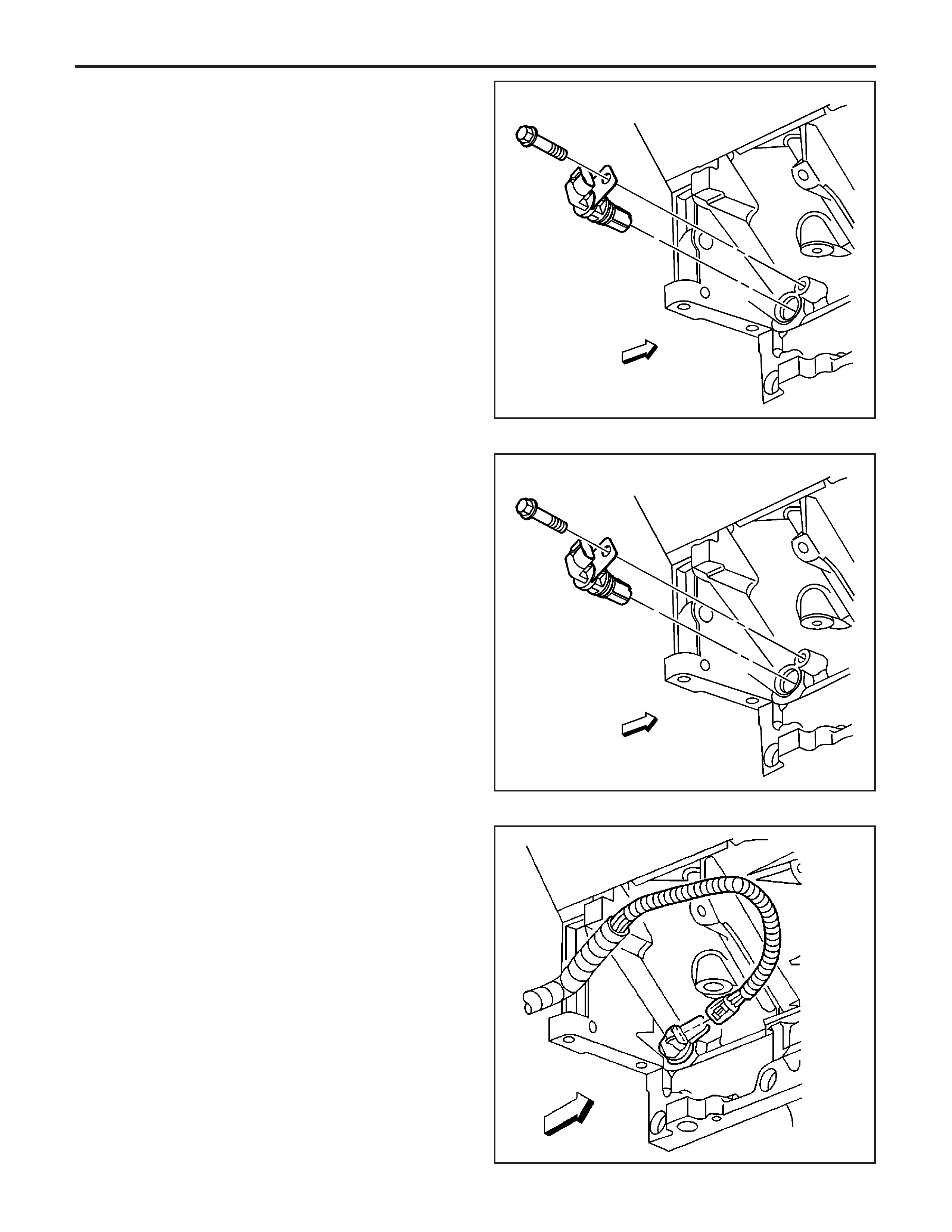
Important: Clean the area around the CKP before
removal in order to avoid debris from entering the
engine.
5. Remove the CKP sensor retaining bolt.
6. Remove the CKP sensor.
Installation Procedure
1. Install the CKP sensor.
Notice:
Refer to
Fastener Notice
in Cautions and
Notices.
2. Install the CKP sensor retaining bolt.
Tighten
Tighten the CKP sensor to 25 N·m (18 lb ft).
3. Connect the CKP sensor electrical connector.
4. Install the starter. Refer to
Starter Motor
Replacement
in Engine Electrical.
5. Lower the vehicle.
6. Connect the negative battery cable.
7. Program the transmitters. Refer to
Transmitter
Programming (Domestic)
or
Transmitter
Programming (Export - Including Canada)
in
Keyless Entry.
8. Perform the CKP System Variation Learn
Procedure. Refer to
CKP System Variation Learn
Procedure
.
55322
55322
56592
EngineEngineControls-6.0L
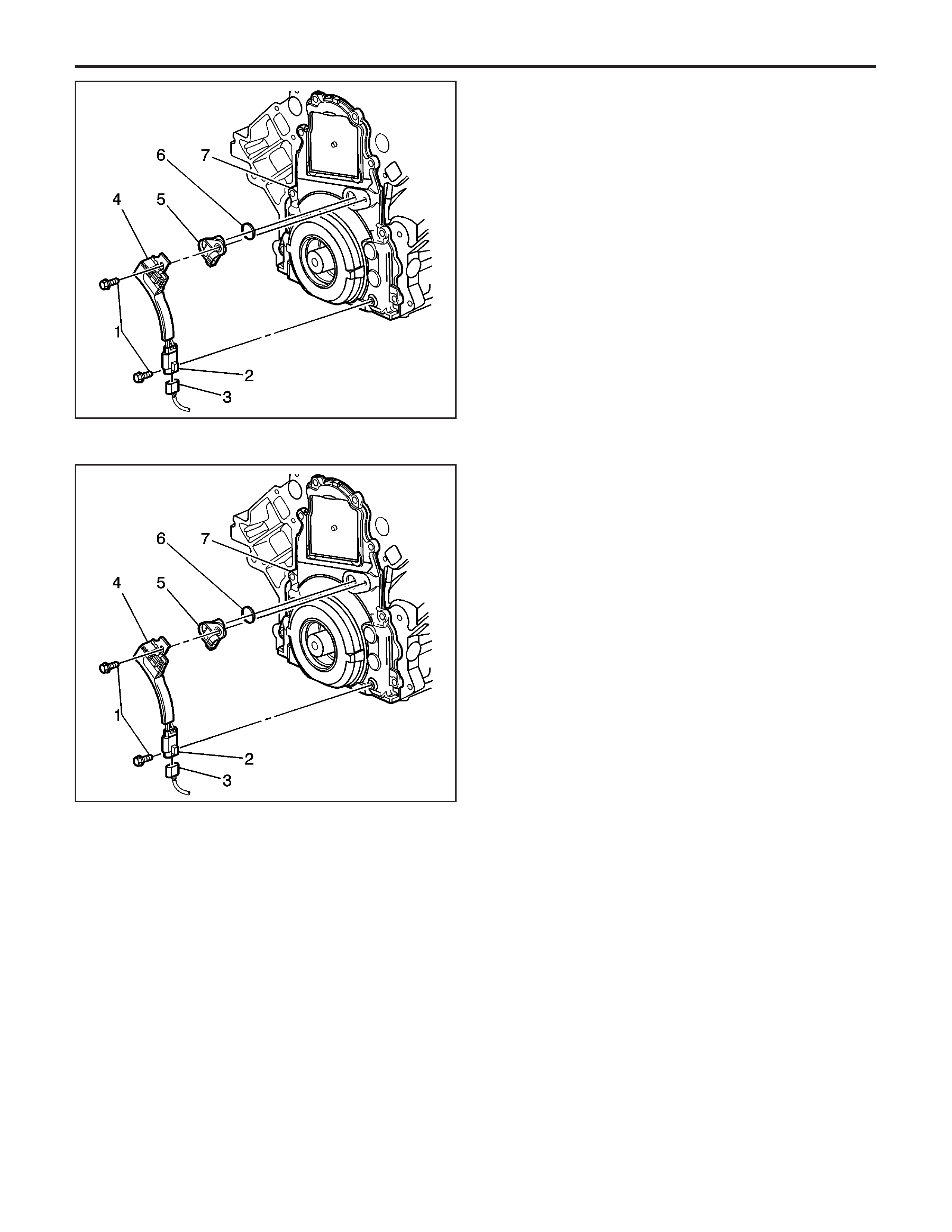
Camshaft Position (CMP) Sensor
Replacement
Removal Procedure
1. Remove the generator bracket assembly. Refer to
Generator Bracket Replacement
in Engine
Electrical.
2. Remove the camshaft position sensor mounting
bolts (1).
3. Remove the camshaft position sensor
assembly (4, 5, 6) from the front cover (7).
4. Disconnect the camshaft position sensor jumper
harness (2) and the engine harness (3) electrical
connectors.
5. Remove the camshaft sensor assembly (4, 5, 6).
6. Disconnect camshaft position sensor (5) from
the jumper harness (4).
Installation Procedure
1. Reconnect the camshaft sensor (5) and the
jumper harness (4).
2. Install the O-ring (6) on the camshaft sensor
assembly (4 and 5).
3. Reconnect the camshaft position sensor
assembly (4, 5 and 6) and the engine harness
connector (3).
Important: Before installing the camshaft sensor
assembly, apply a small amount of clean motor oil to
the O-ring (6).
4. Install the camshaft position sensor assembly (4,
5 and 6) in the front cover (7).
Notice:
Refer to
Fastener Notice
in Cautions and
Notices.
5. Install the camshaft position sensor
mounting bolts.
Tighten
Tighten the camshaft position mounting bolts
25 N·m (18 lb ft).
6. Install the generator assembly. Refer to
Generator
Bracket Replacement
in Engine Electrical.
1484001
1484001
EngineControls-6.0LEngine
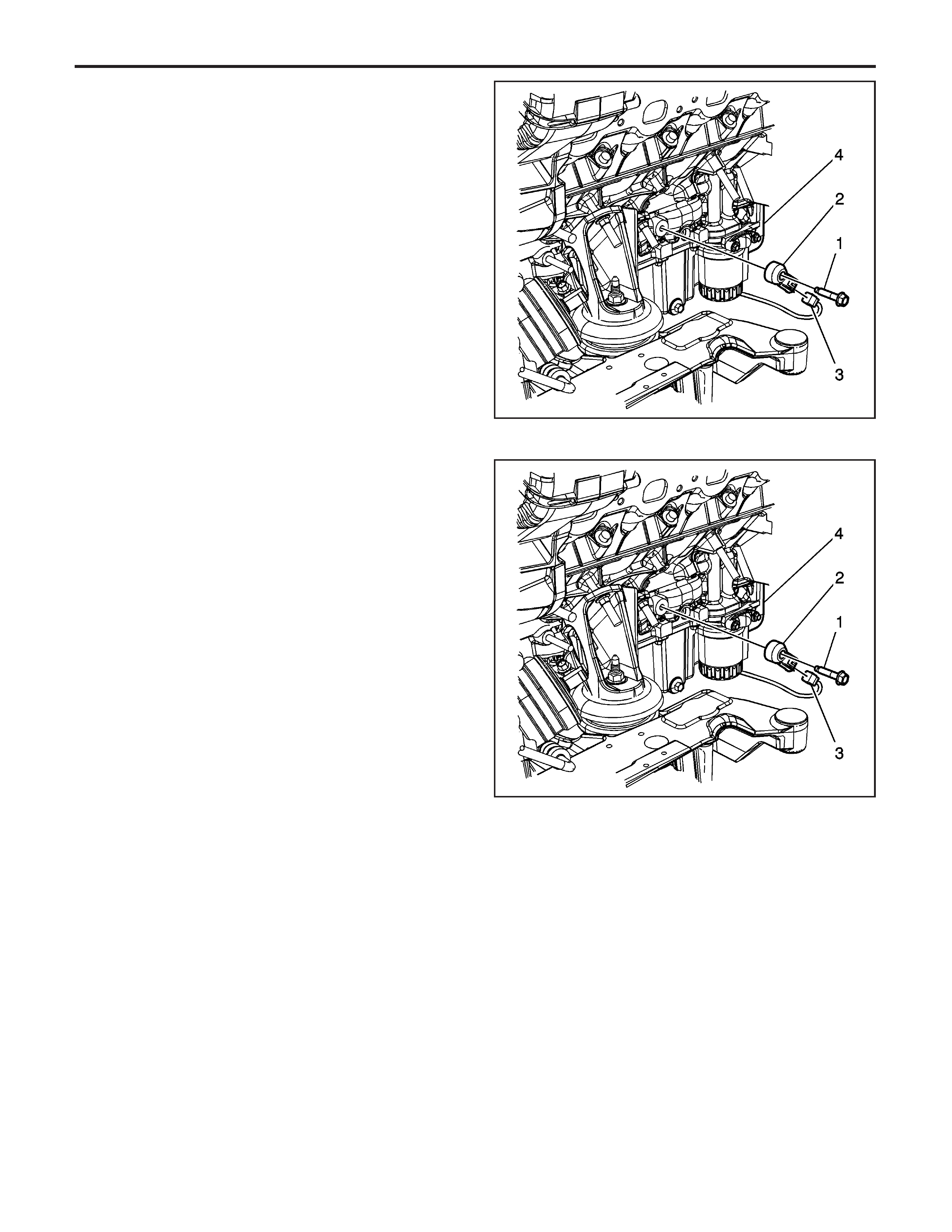
Knock Sensor (KS) Replacement (Left)
Removal Procedure
1. Disconnect the negative battery cable. Refer to
Battery Negative Cable Disconnect/Connect
Procedure
in Engine Electrical.
2. Remove the left exhaust manifold. Refer to
Muffler
Replacement - Left
in Engine Exhaust.
3. Remove the left catalytic convertor. Refer to
Catalytic Converter Replacement (Left)
or
Catalytic Converter Replacement (Right)
in Engine
Exhaust.
4. Remove the mounting bolt for the knock sensor 1.
5. Disconnect the electrical connector of the knock
sensor from the engine harness (3).
6. Remove the knock sensor (2) from the engine
block (4).
Installation Procedure
1. Reconnect the engine harness (3) and the knock
sensor (2) electrical connectors.
2. Position the knock sensor 2 on the engine
block (4).
3. Install the mounting bolt (1) for the knock sensor 2.
Notice:
Refer to
Fastener Notice
in Cautions and
Notices.
4. Tighten the knock sensor mounting bolt (1).
Tighten
Tighten the knock sensor mounting bolt to
20 N·m (15 lb ft).
5. Install the left catalytic convertor. Refer to
Catalytic
Converter Replacement (Left)
or
Catalytic
Converter Replacement (Right)
in Engine Exhaust.
6. Install the left exhaust manifold. Refer to
Muffler
Replacement - Left
in Engine Exhaust.
7. Connect the negative battery cable. Refer to
Battery Negative Cable Disconnect/Connect
Procedure
in Engine Electrical.
8. Program the transmitters. Refer to
Transmitter
Programming (Domestic)
or
Transmitter
Programming (Export - Including Canada)
in
Keyless Entry.
1480894
1480894
EngineEngineControls-6.0L
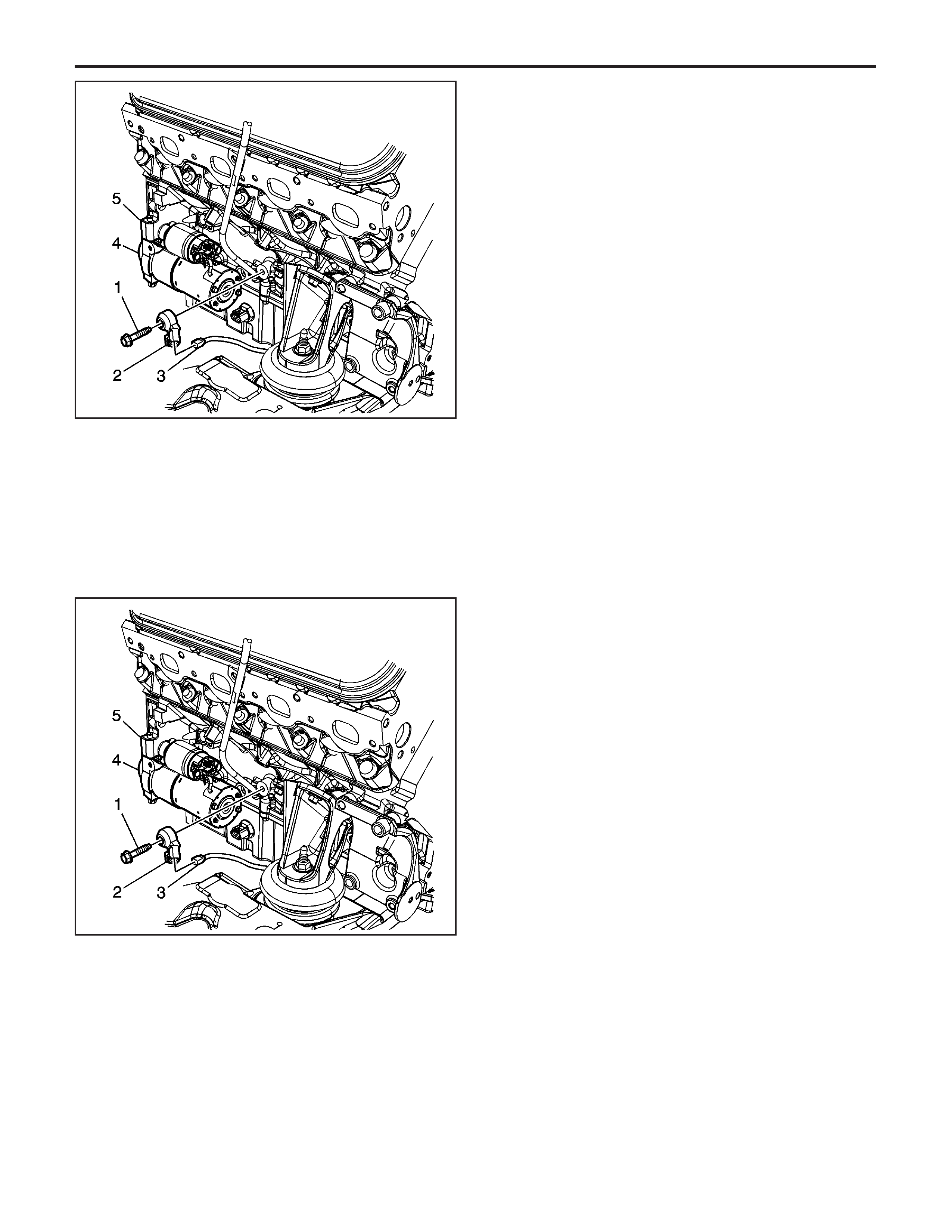
Knock Sensor (KS) Replacement (Right)
Removal Procedure
1. Remove the negative battery cable. Refer to
Battery Negative Cable Replacement
in Engine
Electrical.
2. Remove the right exhaust manifold. Refer to
Exhaust Manifold Replacement - Right
in
Engine Exhaust.
3. Remove the right catalytic convertor. Refer to
Catalytic Converter Replacement (Left)
or
Catalytic Converter Replacement (Right)
in Engine
Exhaust.
Important: In the following service procedure, it
maybe necessary to remove the starter assembly to
gain enough clearance to remove the knock sensor.
4. Remove the starter assembly (4), ONLY IF
NEEDED. Refer to
Starter Motor Replacement
in
Engine Electrical.
5. Remove the knock sensor mounting (1).
6. Remove the knock sensor 2 from the engine
block (5).
7. Disconnect the engine electrical connector (3)
from the knock sensor 2.
8. Remove the knock sensor 2.
Installation Procedure
1. Reconnect electrical connector (3) for the engine
harness to the knock sensor 2.
2. Position the knock sensor 2 on the engine
block (5).
3. Install the mounting bolt (1) for the knock sensor 2.
Notice:
Refer to
Fastener Notice
in Cautions and
Notices.
4. Tighten the knock sensor mounting bolt (1).
Tighten
Tighten the knock sensor mounting
bolt 1 to 20 N·m (15 lb ft).
5. Install the starter assembly (4), ONLY IF
REMOVED. Refer to
Starter Motor Replacement
in Engine Electrical.
6. Install the catalytic convertor. Refer to
Catalytic
Converter Replacement (Left)
or
Catalytic
Converter Replacement (Right)
in Engine Exhaust.
7. Install the right exhaust manifold. Refer to
Exhaust
Manifold Replacement - Right
in Engine Exhaust.
Important: Perform the following procedure only if the
battery has been disconnected.
8. Program the transmitters. Refer to
Transmitter
Programming (Domestic)
or
Transmitter
Programming (Export - Including Canada)
in
Keyless Entry.
9. Install the negative battery cable. Refer to
Battery
Negative Cable Replacement
in Engine Electrical.
1480896
1480896
EngineControls-6.0LEngine
Description and Operation
Engine Control Module (ECM) Description
The powertrain has electronic controls to reduce
exhaust emissions while maintaining excellent
driveability and fuel economy. The engine control
module (ECM) is the control center of this system. The
ECM monitors numerous engine and vehicle
functions. The ECM constantly monitors at the
information from various sensors and other inputs, and
controls the systems that affect vehicle performance
and emissions. The ECM also performs the diagnostic
tests on various parts of the system. The ECM can
recognize operational problems and alert the driver via
the malfunction indicator lamp (MIL). When the
ECM detects a malfunction, the ECM stores a
diagnostic trouble code (DTC). The problem area is
identified by the particular DTC that is set. The control
module supplies a buffered voltage to various
sensors and switches. Review the components and
wiring diagrams in order to determine which systems
are controlled by the ECM.
Malfunction Indicator Lamp (MIL) Operation
The malfunction indicator lamp (MIL) is located in the
instrument panel cluster. The MIL will display as
either SERVICE ENGINE SOON or one of the
following symbols when commanded ON:
SIO-ID = 801183 LMD = 02-aug-2001
The MIL indicates that an emissions related fault has
occurred and vehicle service is required.
The following is a list of the modes of operation for
the MIL:
• The MIL illuminates when the ignition is turned
ON, with the engine OFF. This is a bulb test
to ensure the MIL is able to illuminate.
• The MIL turns OFF after the engine is started if a
diagnostic fault is not present.
• The MIL remains illuminated after the engine is
started if the control module detects a fault. A
diagnostic trouble code (DTC) is stored any time
the control module illuminates the MIL due to
an emissions related fault. The MIL turns
OFF after three consecutive ignition cycles in
which a Test Passed has been reported for the
diagnostic test that originally caused the MIL
to illuminate.
800893
802451
EngineEngineControls-6.0L

• The MIL flashes if the control module detects a
misfire condition which could damage the
catalytic converter.
• When the MIL is illuminated and the engine stalls,
the MIL will remain illuminated as long as the
ignition is ON.
• When the MIL is not illuminated and the engine
stalls, the MIL will not illuminate until the ignition
is cycled OFF and then ON.
Throttle Actuator Control (TAC) System
Description
Purpose
The throttle actuator control (TAC) system delivers
improved throttle response and greater reliability and
eliminates the need for mechanical cable. The
TAC system performs the following functions:
• Accelerator pedal position sensing
• Throttle positioning to meet driver and engine
demands
• Throttle position sensing
• Internal diagnostics
• Cruise control functions
• Manage TAC electrical power consumption
The TAC system includes the following components:
• The accelerator pedal position (APP) sensors
• The throttle body assembly
• The engine control module (ECM)
Accelerator Pedal Position (APP) Sensor
The accelerator pedal contains 2 individual APP
sensors within the assembly. The APP sensors 1 and
2 are potentiometer type sensors each with 3 circuits:
• A 5-volt reference circuit
• A low reference circuit
• A signal circuit
The APP sensors are used to determine the pedal
angle. The ECM provides each APP sensor a
5-volt reference circuit and a low reference circuit. The
APP sensors provide the ECM with signal voltage
proportional to the pedal movement. The APP sensor 1
signal voltage at rest position is less than 1 volt and
increases to above 2.5 volts as the pedal is actuated.
The APP sensor 2 signal voltage at rest position is
near the 4 volts and decreases to less than 1 volt as
the pedal is actuated.
Throttle Body Assembly
The throttle assembly contains the following
components:
• The throttle blade
• The throttle actuator motor
• The throttle position (TP) sensor 1 and 2
The throttle body functions similar to a conventional
throttle body with the following exceptions:
• An electric motor opens and closes the
throttle valve.
• The throttle blade is spring loaded in both
directions and the default position is slightly open.
• There are 2 individual TP sensors within the
throttle body assembly.
The TP sensors are used to determine the throttle
plate angle. The TP sensors provide the ECM with a
signal voltage proportional to throttle plate movement.
The TP sensor 1 signal voltage at closed throttle is
above 4 volts and decreases as the throttle plate
is opened. The TP sensor 2 signal voltage at closed
throttle is below 1 volt and increases as the throttle
plate is opened.
Engine Control Module
The ECM is the control center for the TAC system.
The ECM determines the drivers intent and then
calculates the appropriate throttle response. The ECM
achieves throttle positioning by providing a pulse
width modulated voltage to the TAC motor.
Modes of Operation
Normal Mode
During the operation of the TAC system, several
modes or functions are considered normal. The
following modes may be entered during normal
operation:
• Minimum pedal value—At key-up the ECM
updates the learned minimum pedal value.
• Minimum TP values—At key-up the ECM updates
the learned minimum TP value. In order to learn
the minimum TP value, the throttle blade is moved
to the closed position.
• Ice break mode—If the throttle is not able to reach
a predetermined minimum throttle position, the ice
break mode is entered. During the ice break
mode, the ECM commands the maximum pulse
width several times to the throttle actuator motor in
the closing direction.
• Battery saver mode—After a predetermined time
without engine RPM, the ECM commands the
battery saver mode. During the battery saver
mode, the TAC module removes the voltage from
the motor control circuits, which removes the
current draw used to maintain the idle position and
allows the throttle to return to the spring loaded
default position.
Reduced Engine Power Mode
When the ECM detects a condition with the TAC
system, the ECM may enter a reduced engine power
mode. Reduced engine power may cause one or
more of the following conditions:
• Acceleration limiting—The ECM will continue to
use the accelerator pedal for throttle control;
however, the vehicle acceleration is limited.
• Limited throttle mode—The ECM will continue to
use the accelerator pedal for throttle control;
however, the maximum throttle opening is limited.
EngineControls-6.0LEngine
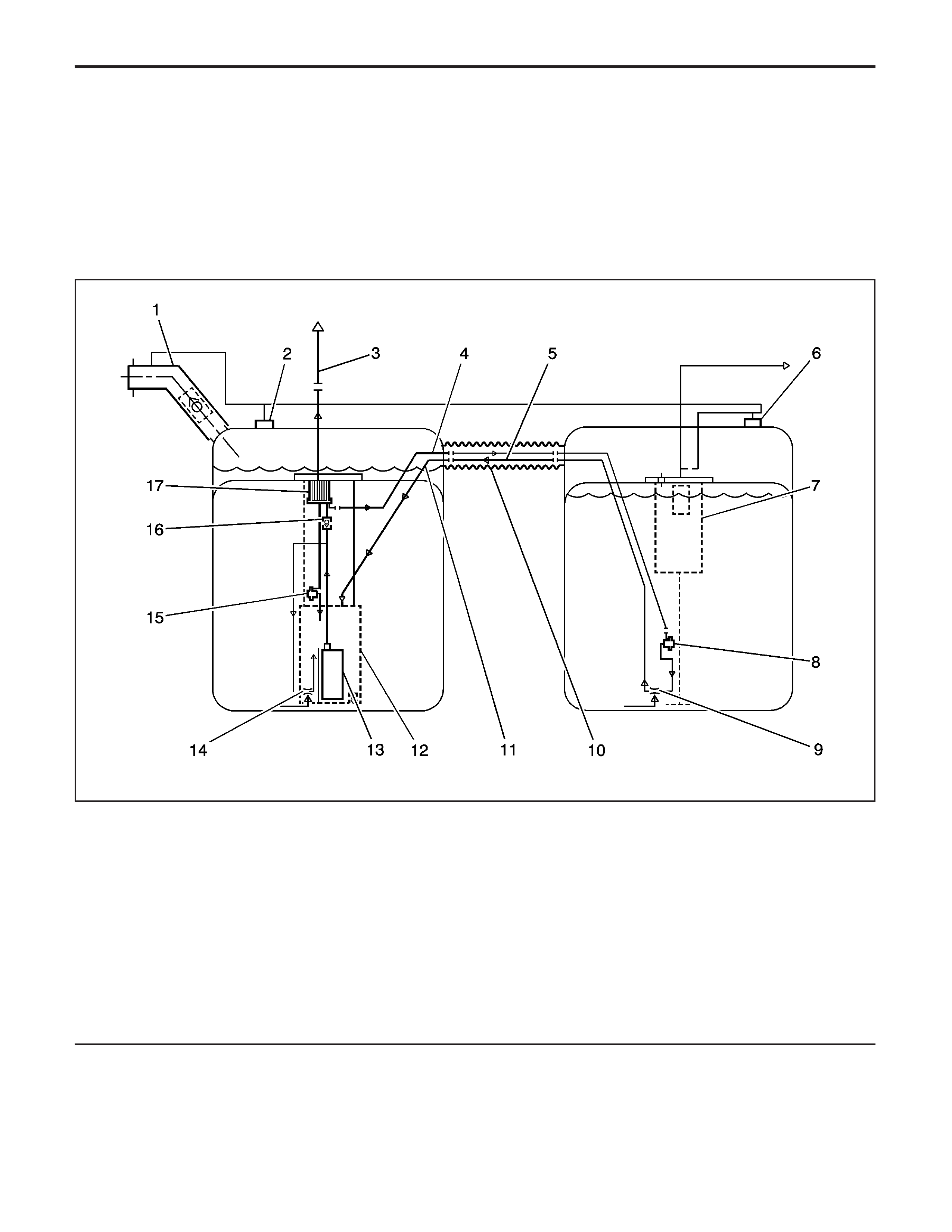
• Throttle default mode—The ECM will turn off the
throttle actuator motor and the throttle will
return to the spring loaded default position.
• Forced idle mode—The ECM will perform the
following actions:
− Limit engine speed to idle by positioning the
throttle position, or by controlling the fuel
and spark if the throttle is turned off.
− Ignore the accelerator pedal input.
• Engine shutdown mode—The ECM will disable
fuel and de-energize the throttle actuator.
Fuel System Description
System Overview
Legend
(1) Fuel Fill Hose
(2) Left Fuel Tank Grade Vent Valve
(3) Fuel Feed Pipe to Engine
(4) 5/16 Inch Auxiliary Fuel Feed Pipe
(5) 3/8 Inch Auxiliary Fuel Return Pipe
(6) Right Fuel Tank Grade Vent Valve
(7) Fill Limiter Vent Valve (FLVV)
(8) Secondary Fuel Pressure Regulator
(9) Siphon Jet Pump
(10) Convoluted Crossover Hose
(11) Anti-siphon Hole
(12) Fuel Sender Reservoir
(13) Turbine Fuel Pump
(14) Venturi Pump
(15) Primary Fuel Pressure Regulator
(16) Reverse Flow Check Valve
(17) Fuel Filter
877203
EngineEngineControls-6.0L

The fuel system is a returnless on-demand design.
The fuel pressure regulator is a part of the fuel sender
assembly, eliminating the need for a return pipe
from the engine. A returnless fuel system reduces the
internal temperature of the fuel tank by not returning
hot fuel from the engine to the fuel tank. Reducing the
internal temperature of the fuel tank results in lower
evaporative emissions.
Two fuel tanks store the fuel supply. An electric
turbine style fuel pump (13) attaches to the fuel sender
assembly inside the left fuel tank. The fuel pump
supplies high pressure fuel through the fuel filter (17)
and the fuel feed pipe (3) to the fuel injection
system. The fuel pump provides fuel at a higher rate
of flow than is needed by the fuel injection system. The
fuel pump also supplies fuel to the venturi pump
(14) located on the bottom of the left fuel sender
assembly. The function of the venturi pump is to fill the
fuel sender assembly reservoir (12). The primary
fuel pressure regulator (15), a part of the left
fuel sender assembly, maintains the correct fuel
pressure to the fuel injection system. The fuel pump
and sender assembly contains a reverse flow
check valve (16). The check valve, the primary fuel
pressure regulator, and the secondary fuel pressure
regulator maintain fuel pressure in the fuel feed
pipe and the fuel rail in order to prevent long
cranking times.
The fuel pump also supplies a small amount of
pressurized fuel through the auxiliary fuel feed pipe (4)
to the siphon jet pump (9) inside the right fuel tank.
The pressurized fuel creates a venturi action inside the
siphon jet pump. The venturi action causes the fuel
to be drawn out of the right fuel tank. The fuel transfers
from the right fuel tank to the left fuel tank through
the auxiliary fuel return pipe (5). The auxiliary
fuel return pipe inside the left fuel tank contains an
anti-siphon hole (11) in order to prevent fuel from
siphoning from the left fuel tank into the right fuel tank.
Both the auxiliary fuel feed pipe and the auxiliary
fuel return pipe are located inside the convoluted
stainless steel crossover hose (10).
The right fuel sender assembly contains a secondary
fuel pressure regulator (8). The secondary fuel
pressure regulator has a lower set point than the
primary regulator in order to allow fuel to flow to the
siphon jet pump on the right fuel sender. When
the engine is shut off, the pressure in the feed pipes
immediately drops to the secondary regulator set point.
This prevents the siphon jet pump from operating
and in turn prevents the equalization of the left and
right fuel tanks. The secondary fuel pressure regulator
maintains fuel pressure in the auxiliary fuel feed
pipe which reduces the time to prime the siphon jet
pump. The pressurization also reduces fuel
vaporization and boiling in the auxiliary fuel feed pipe.
Fuel Tanks
The fuel tanks (6, 8) store the fuel for the vehicle. The
fuel tanks are located on the left and right side of
the vehicle in front of the rear wheels. The fuel tanks
are molded from high density polyethylene.
Fuel Tank Fill Pipe and Hose
The fuel tank fill pipe is positioned at the rear of the
vehicle on the left side. A built in restrictor in the
fuel tank fill pipe prevents refueling with leaded fuel.
The fuel tank fill pipe connects to the left fuel tank with
a rubber hose. Fuel transfers to the right fuel tank
during fueling by a stainless steel convoluted crossover
tube/hose which connects the left fuel tank to the
right fuel tank.
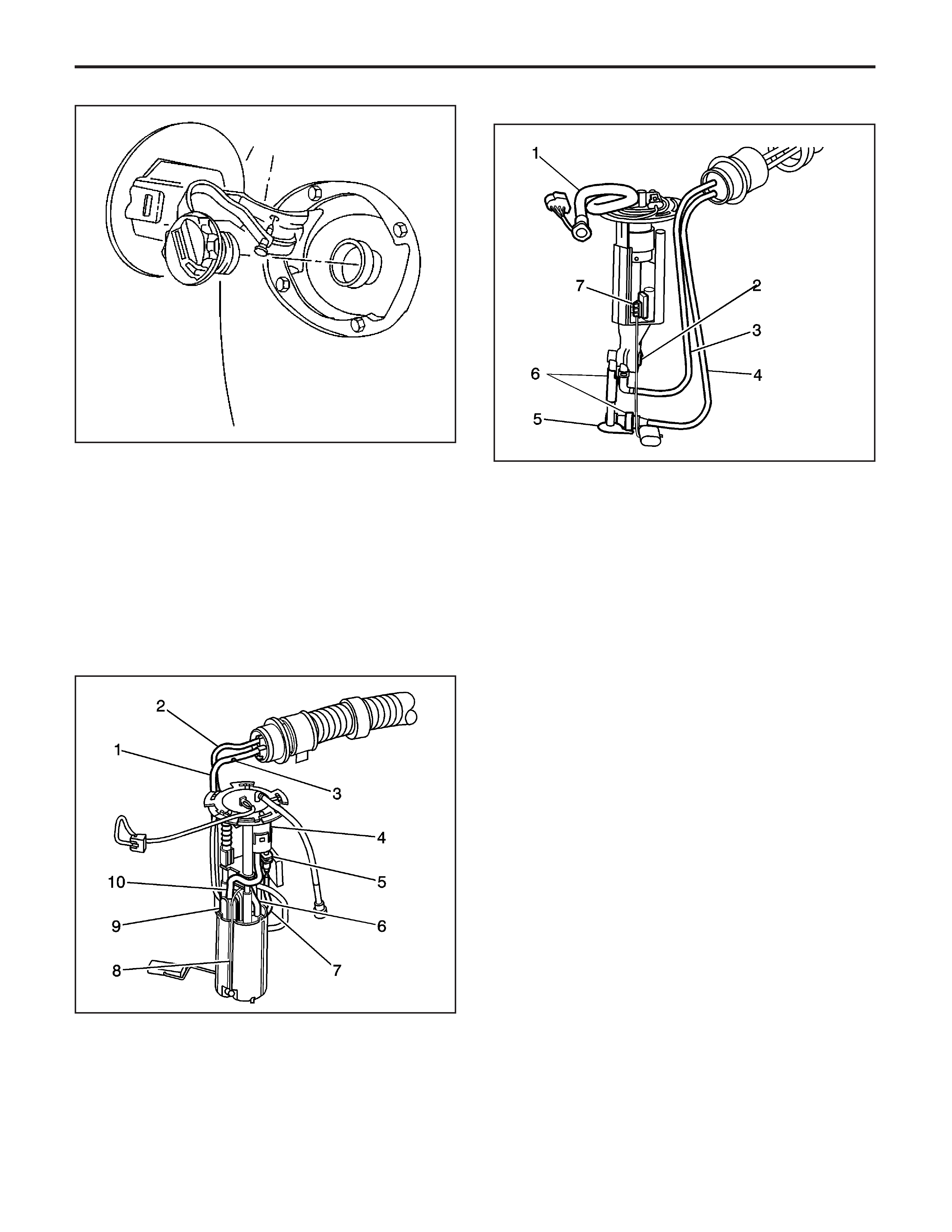
Fuel Filler Cap
Notice:
Ifafueltank
filler cap requires replacement, use only a fuel
tank filler cap with the same features. Failure to use
the correct fuel tank filler cap can result in a
serious malfunction of the fuel and EVAP system.
The fuel tank filler pipe has a tethered fuel tank filler
cap. The fuel tank filler cap requires a quarter of a turn
in order to be removed. A torque limiting device
prevents the cap from being over tightened.
Fuel Sender Assembly
A fuel sender assembly is located inside each fuel
tank. The fuel sender assembly attaches to the top of
each fuel tank. The left fuel sender assembly
consists of the following major components:
• The fuel level sensor
• The fuel pump and reservoir assembly
• The fuel pump strainer
• The fuel filter (4)
• The primary fuel pressure regulator (9)
The right fuel sender assembly consists of the
following major components:
• The fuel level sensor (7)
• The siphon jet pump (5)
• The secondary fuel pressure regulator (2)
• The fill limiter vent valve (FLVV)
Fuel Level Sensor
The fuel level sensor consists of a float, a wire float
arm, and a variable resistor. The position of the
float arm indicates the fuel level. The fuel level sensor
contains a variable resistor, which changes the
resistance corresponding to the amount of fuel in the
fuel tanks. The PCM uses inputs from both fuel
level sensors in order to calculate the total fuel
remaining in both fuel tanks. This information is sent
via a Class 2 message to the instrument panel
cluster (IPC) to be displayed on the fuel gage.
Fuel Pump
An electric turbine style fuel pump attaches to the fuel
sender assembly inside the left fuel tank. The fuel
pump supplies fuel to the fuel rail assembly at
a specified flow and pressure. The fuel pump delivers
a constant flow of fuel to the engine even during
low fuel conditions and aggressive vehicle maneuvers.
The PCM controls the electric fuel pump operation
through a fuel pump relay.
The fuel pump also supplies a small amount of
pressurized fuel to the right fuel tank siphon jet pump
through the auxiliary fuel feed pipe. The pressurized
fuel creates a venturi action inside the siphon jet pump.
The venturi action causes the fuel to be drawn out
of the right fuel tank. Fuel is then transferred from the
right fuel tank to the left fuel tank through the
auxiliary fuel return pipe. The fuel pump also supplies
fuel to a venturi pump located on the bottom of the
left fuel sender assembly. The function of the venturi
pump is to fill the fuel sender assembly reservoir.
43529
877216
877232
EngineEngineControls-6.0L

Fuel Strainer
The fuel strainer is made of woven plastic. The
functions of the fuel strainer are to filter the
contaminants and to wick the fuel. The fuel strainer
attaches to the bottom of the fuel pump inside of
the fuel sender reservoir. The fuel strainer normally
requires no maintenance. Fuel stoppage at this
point indicates that the fuel tanks contain an abnormal
amount of sediment. If the fuel strainer is plugged,
refer to
Fuel System Cleaning
.
Fuel Filter
The fuel filter is contained in the fuel sender assembly
inside the left fuel tank. The paper filter element of
the fuel filter traps particles in the fuel that may
damage the fuel injection system. The fuel filter
housing is made to withstand maximum fuel system
pressure, exposure to fuel additives, and changes
in temperature. There is no service interval for
fuel filter replacement.
Primary Fuel Pressure Regulator
The primary fuel pressure regulator is contained in the
left fuel sender assembly. The fuel pressure regulator
is a diaphragm relief valve. The diaphragm has
fuel pressure on one side and regulator spring
pressure on the other side. A software bias
compensates the injector on-time because the fuel
pressure regulator is not referenced to the manifold
vacuum. The primary fuel pressure regulator
keeps fuel available to the injectors at a regulated
pressure.
Secondary Fuel Pressure Regulator
The right fuel sender assembly contains a secondary
fuel pressure regulator. The secondary fuel pressure
regulator has a lower set point than the primary
regulator in order to allow fuel to flow to the siphon jet
pump on the right fuel sender. When the engine is
shut off, the pressure in the feed pipes immediately
drops to the secondary regulator set point. This
prevents the siphon jet pump from operating and in
turn prevents the equalization of the left and right fuel
tanks. The secondary fuel pressure regulator
maintains fuel pressure in the auxiliary fuel feed pipe
which reduces the time to prime the siphon jet
pump. The pressurization also reduces fuel
vaporization and boiling in the auxiliary fuel feed pipe.
Fuel Feed and Return Pipes
The engine compartment connecting fuel pipe
connects the chassis fuel pipe to the fuel rail assembly.
The engine compartment fuel pipe is constructed of
Teflon
®
with a braided stainless steel covering.
The chassis fuel pipe is located under the vehicle on
the left side of the tunnel. The chassis fuel pipe
connects the rear fuel feed pipe from the left fuel
sender assembly to the engine compartment
connecting fuel pipe. The chassis fuel pipe is
constructed of aluminum with a plastic coating.
The rear fuel feed pipe connects the left fuel sender
fuel pipe to the chassis fuel pipe. The rear fuel
feed pipe is constructed of nylon with a covering of
heat resistant rubber hose.
The auxiliary fuel feed pipes and the auxiliary fuel
return pipes are located inside of the fuel crossover
hose and inside of each fuel tank. The fuel pump
supplies fuel through the auxiliary fuel feed pipe to the
siphon jet pump inside the right fuel tank. The
siphon jet pump transfers fuel from the right fuel tank
to the left fuel tank through the auxiliary fuel return
pipe. The return pipe feeds returning fuel from the right
fuel tank directly into the left fuel sender reservoir.
The auxiliary fuel feed and return pipes are
constructed of nylon.
The fuel tank crossover tube/hose is comprised of a
convoluted stainless steel outer tubing. The crossover
tube/hose internally houses the auxiliary fuel feed
pipe and the auxiliary fuel return pipe. The crossover
tube/hose has the following functions:
• Fuel liquid and vapor transfer during refueling
• High pressure siphon jet pump feed
• Low pressure siphon jet pump return
• Electrostatic discharge ground to body
Nylon Fuel Pipes
Caution:Inorderto
reduce the risk of fire and personal injury observe
the following items:
•
Replace all nylon fuel pipes that are nicked,
scratched or damaged during installation,
do not attempt to repair the sections of
the nylon fuel pipes
•
Do not hammer directly on the fuel harness
body clips when installing new fuel pipes.
Damage to the nylon pipes may result in
a fuel leak.
•
Always cover nylon vapor pipes with a wet
towel before using a torch near them. Also,
never expose the vehicle to temperatures
higher than 115°C (239°F) for more than
one hour, or more than 90°C (194°F) for any
extended period.
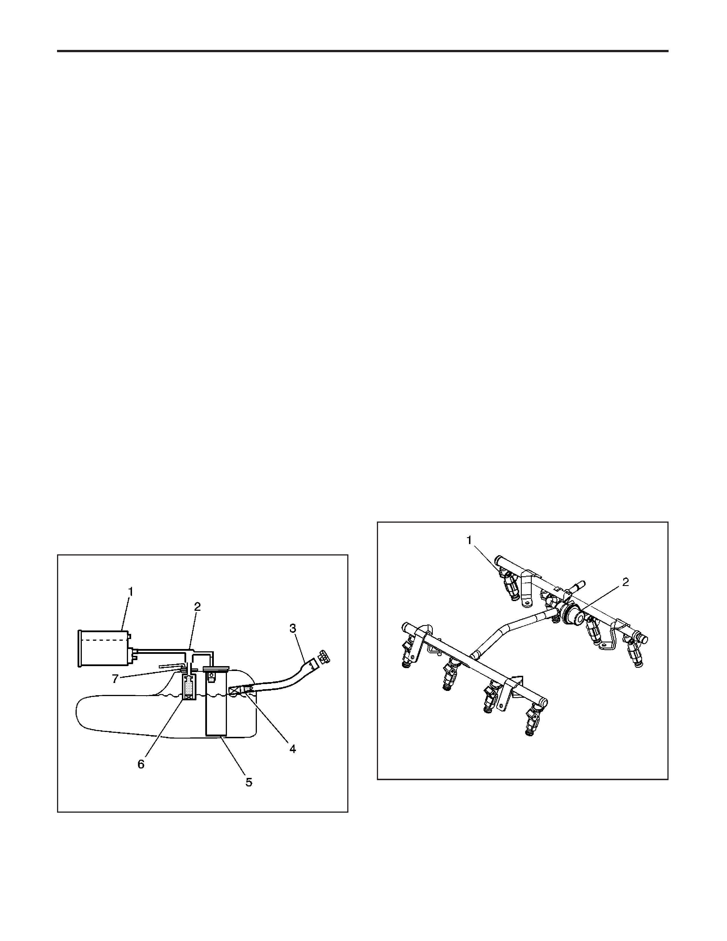
•
Apply a few drops of clean engine oil to the
male pipe ends before connecting fuel pipe
fittings. This will ensure proper reconnection
and prevent a possible fuel leak. (During
normal operation, the O-rings located in the
female connector will swell and may prevent
proper reconnection if not lubricated.)
Nylon pipes are constructed to withstand maximum
fuel system pressure, exposure to fuel additives, and
changes in temperature. There are 2 sizes of nylon
fuel pipes used. A 9.53 mm (3/8 in) ID pipe is used for
the fuel feed pipe and the auxiliary fuel return pipe.
A 7.94 mm (5/16 in) ID pipe is used for the auxiliary
fuel feed pipe. Heat resistant rubber hose protects the
section of the rear fuel feed pipe that is exposed to
chafing, high temperature or vibration.
Nylon fuel pipes are somewhat flexible and can be
formed around gradual turns under the vehicle.
However, if nylon fuel pipes are forced into sharp
bends, the pipes will kink and restrict the fuel
flow. Also, once exposed to the fuel, nylon pipes may
become stiffer and are more likely to kink if bent
too far. Take special care when working on a vehicle
with nylon fuel pipes.
Quick-Connect Fittings
Quick-connect fittings provide a simplified means of
installing and connecting fuel system components. The
fittings consist of a unique female connector and a
compatible male pipe end. O-rings located inside the
female connector provide the fuel seal. Integral
locking tabs located inside the female connector hold
the fittings together.
On-Board Refueling Vapor Recovery
System (ORVR)
The on-board refueling vapor recovery system (ORVR)
is an on board vehicle system designed to recover
fuel vapors during the vehicle refueling operation. The
flow of liquid fuel down the fuel filler pipe provides
a liquid seal which prevents vapor from leaving the fuel
filler pipe. An EVAP pipe transports the fuel vapor to
the EVAP canister for use by the engine. Listed below
are the ORVR system components with a brief
description of their operation:
• The EVAP canister (1)—the EVAP canister
receives refueling vapor from the fuel system,
stores the vapor and releases the vapor to
the engine upon demand.
• The EVAP pipes (2)—transports fuel vapor from
the fuel tank to the EVAP canister.
• The fuel filler pipe (3)—the pipe which carries fuel
from the fuel nozzle to the fuel tank.
• The check valve (4)—the check valve limits fuel
“spit back” from the fuel tank during the refueling
operation by allowing fuel flow only into the
fuel tank. This check valve is located at the bottom
of the fuel filler pipe.
• The modular fuel sender assembly (5)—this
assembly pumps fuel to the engine from the
fuel tank.
• The fill limiter vent valve (FLVV) (6)—this valve
acts as a shut off valve. The FLVV is located
on the right fuel sender. This valve is not serviced
separately. The FLVV has the following functions:
− Controls the fuel tank fill level by closing the
primary vent from the fuel tank.
− Prevents the fuel from exiting the fuel tank
via the EVAP pipe to the canister.
− Provides fuel-spillage protection in the event
of a vehicle rollover by closing the vapor
path from the fuel tank to the EVAP canister.
Fuel Rail Assembly
The fuel rail assembly attaches to the engine intake
manifold. The fuel rail assembly performs the following
functions:
• Positions the injectors (1) in the intake manifold
• Distributes the fuel evenly to the injectors
• Integrates the fuel pulse dampener (2) into the
fuel metering system
178033
217109
EngineEngineControls-6.0L

Fuel Injectors
The fuel injector assembly is a solenoid device,
controlled by the PCM, that meters pressurized fuel to
a single engine cylinder. The PCM energizes the
injector solenoid to open a normally closed ball valve.
This allows the fuel to flow into the top of the
injector, past the ball valve, and through a director
plate at the injector outlet. The director plate has
machined holes that control the fuel flow, generating a
spray of finely-atomized fuel at the injector tip. Fuel
from the injector tip is directed at the intake valve,
causing the fuel to become further atomized and
vaporized before entering the combustion chamber.
This fine atomization improves fuel economy and
emissions.
Fuel Metering Modes of Operation
The PCM monitors voltages from several sensors in
order to determine how much fuel to give the
engine. The PCM controls the amount of fuel delivered
to the engine by changing the fuel injector pulse
width. The fuel is delivered under one of
several modes.
Starting Mode
When the ignition is first turned ON, the PCM
energizes the fuel pump relay for 2 seconds. This
allows the fuel pump to build pressure in the fuel
system. The PCM calculates the air/fuel ratio based
on inputs from the engine coolant temperature (ECT),
mass air flow (MAF), manifold absolute
pressure (MAP), and throttle position (TP) sensors.
The system stays in starting mode until the engine
speed reaches a predetermined RPM.
Clear Flood Mode
If the engine floods, clear the engine by pressing the
accelerator pedal down to the floor and then crank
the engine. When the TP sensor is at wide open
throttle (WOT), the PCM reduces the fuel injector pulse
width in order to increase the air to fuel ratio. The
PCM holds this injector rate as long as the throttle
stays wide open and the engine speed is below
a predetermined RPM. If the throttle is not held wide
open, the PCM returns to the starting mode.
Run Mode
The run mode has 2 conditions called Open Loop and
Closed Loop. When the engine is first started and
the engine speed is above a predetermined RPM, the
system begins Open Loop operation. The PCM
ignores the signal from the heated oxygen sensors
(HO2S). The PCM calculates the air/fuel ratio
based on inputs from the ECT, MAF, MAP, and TP
sensors. The system stays in Open Loop until meeting
the following conditions:
• Both front HO2S have varying voltage output,
showing that both HO2S are hot enough to
operate properly.
• The ECT sensor is above a specified temperature.
• A specific amount of time has elapsed after
starting the engine.
Specific values for the above conditions exist for each
different engine, and are stored in the electrically
erasable programmable read-only memory (EEPROM).
The system begins Closed Loop operation after
reaching these values. In Closed Loop, the PCM
calculates the air/fuel ratio, injector ON time, based
upon the signal from various sensors, but mainly from
the HO2S. This allows the air/fuel ratio to stay very
close to 14.7:1.
Acceleration Mode
When the driver pushes on the accelerator pedal, air
flow into the cylinders increases rapidly. To prevent
possible hesitation, the PCM increases the pulse width
to the injectors to provide extra fuel during
acceleration. This is also known as power enrichment.
The PCM determines the amount of fuel required
based upon the TP, the ECT, the MAP, the MAF, and
the engine speed.
Deceleration Mode
When the driver releases the accelerator pedal, air
flow into the engine is reduced. The PCM monitors the
corresponding changes in the TP, the MAP, and the
MAF. The PCM shuts OFF fuel completely if the
deceleration is very rapid, or for long periods, such as
long, closed-throttle coast-down. The fuel shuts
OFF in order to prevent damage to the catalytic
converters.
Battery Voltage Correction Mode
When the battery voltage is low, the PCM
compensates for the weak spark delivered by the
ignition system in the following ways:
• Increasing the amount of fuel delivered
• Increasing the idle RPM
• Increasing the ignition dwell time
Fuel Cutoff Mode
The PCM cuts OFF fuel from the fuel injectors when
the following conditions are met in order to protect the
powertrain from damage and improve driveability:
• The ignition is OFF. This prevents engine run-on.
• The ignition is ON but there is no ignition
reference signal. This prevents flooding or
backfiring.
• The engine speed is too high, above red line.
• The vehicle speed is too high, above rated
tire speed.
• During an extended, high speed, closed throttle
coast down—This reduces emissions and
increases engine braking.
• During extended deceleration, in order to prevent
damage to the catalytic converters
Fuel Trim
The PCM controls the air/fuel metering system in
order to provide the best possible combination
of driveability, fuel economy, and emission control.
The PCM monitors the HO2S signal voltage while in
Closed Loop and regulates the fuel delivery by
adjusting the pulse width of the injectors based on this
signal. The ideal fuel trim values are around 0 percent
for both short and long term fuel trim. A positive
fuel trim value indicates the PCM is adding fuel in
EngineControls-6.0LEngine

order to compensate for a lean condition by increasing
the pulse width. A negative fuel trim value indicates
that the PCM is reducing the amount of fuel in order to
compensate for a rich condition by decreasing the
pulse width. A change made to the fuel delivery
changes the long and short term fuel trim values. The
short term fuel trim values change rapidly in
response to the HO2S signal voltage. These changes
fine tune the engine fueling. The long term fuel trim
makes coarse adjustments to fueling in order to
re-center and restore control to short term fuel trim. A
Tech 2 canbeusedtomonitortheshortand
long term fuel trim values. The long term fuel trim
diagnostic is based on an average of several of the
long term speed load learn cells. The PCM selects the
cells based on the engine speed and engine load. If
the PCM detects an excessively lean or rich condition,
the PCM will set a fuel trim diagnostic trouble
code (DTC).
Evaporative Emission (EVAP) Control
System Description
EVAP System Operation
The evaporative emission (EVAP) control system limits
fuel vapors from escaping into the atmosphere. Fuel
tank vapors are allowed to move from the fuel
tank, due to pressure in the tank, through the vapor
pipe, into the EVAP canister. Carbon in the canister
absorbs and stores the fuel vapors. Excess pressure is
vented through the vent line and EVAP vent solenoid
valve to the atmosphere. The EVAP canister stores
the fuel vapors until the engine is able to use them. At
an appropriate time, the control module will command
the EVAP purge solenoid valve ON, allowing engine
vacuum to be applied to the EVAP canister. With
the EVAP vent solenoid valve OFF, fresh air is drawn
through the vent solenoid valve and the vent line to
the EVAP canister. Fresh air is drawn through
the canister, pulling fuel vapors from the carbon. The
air/fuel vapor mixture continues through the EVAP
purge pipe and EVAP purge solenoid valve into
the intake manifold to be consumed during normal
combustion. The control module uses several tests to
determine if the EVAP system is leaking.
Large Leak Test
This tests for large leaks and blockages in the
evaporative emission (EVAP) system. The control
module commands the EVAP vent solenoid valve ON
and commands the EVAP purge solenoid valve
ON, with the engine running, allowing engine vacuum
into the EVAP system. The control module monitors
the fuel tank pressure (FTP) sensor voltage to
verify that the system is able to reach a predetermined
level of vacuum within a set amount of time. The
control module then commands the EVAP purge
solenoid valve OFF, sealing the system, and monitors
the vacuum level for decay. If the control module
does not detect that the predetermined vacuum level
was achieved, or the vacuum decay rate is more
than a calibrated level on 2 consecutive tests,
DTC P0455 will set.
Small Leak Test
The engine off natural vacuum (EONV) diagnostic is
the small-leak detection diagnostic for the evaporative
emission (EVAP) system. While previous leak
detection methods were performed with the engine
running, the EONV diagnostic monitors the EVAP
system pressure or vacuum with the ignition OFF.
Because of this, it may be normal for the control
module to remain active for up to 40 minutes after the
ignition is turned OFF. This is important to remember
when performing a parasitic draw test on vehicles
equipped with EONV.
The EONV utilizes the temperature changes in the
fuel tank immediately following a drive cycle to use the
naturally occurring vacuum or pressure in the fuel
tank. When the vehicle is driven, the temperature rises
in the tank. After the vehicle is parked, the temperature
in the tank continues to rise for a period of time,
then starts to drop. The EONV diagnostic relies on
this temperature change and the corresponding
pressure change in a sealed system, to determine if
an EVAP system leak is present.
The EONV diagnostic is designed to detect leaks as
small as 0.51 mm (0.020 in). The diagnostic can
determine if a small leak is present based on vacuum
or pressure readings in the EVAP system. When
the system is sealed, a finite amount of pressure or
vacuum will be observed. When a 0.51 mm (0.020 in)
leak is present, often little or no pressure or vacuum
is observed. If the test reports a failing value,
DTC P0442 will set.
Canister Vent Restriction Test
If the evaporative emission (EVAP) vent system is
restricted, fuel vapors will not be properly purged from
the EVAP canister. The control module tests this by
commanding the EVAP purge solenoid valve ON,
commanding the EVAP vent solenoid valve OFF, and
monitoring the fuel tank pressure (FTP) sensor for
an increase in vacuum. If the vacuum increases more
than a calibrated value, DTC P0446 will set.
Purge Solenoid Valve Leak Test
If the evaporative emission (EVAP) purge solenoid
valve does not seal properly fuel vapors could
enter the engine at an undesired time, causing
driveability concerns. The control module tests for this
by commanding the EVAP purge solenoid valve
OFF and the vent solenoid valve ON, sealing the
system, and monitors the fuel tank pressure (FTP) for
an increase in vacuum. If the control module detects
that the EVAP system vacuum increases above a
calibrated value, DTC P0496 will set.
Check Gas Cap Message
The powertrain control module (PCM) sends a class 2
message to the driver information center (DIC)
illuminating the Check Gas Cap message when any of
the following occur:
• A malfunction in the evaporative emission (EVAP)
system and a large leak test fails
• A malfunction in the EVAP system and a small
leak test fails
EngineEngineControls-6.0L

EVAP System Components
The evaporative emission (EVAP) system consists of
the following components:
EVAP Canister
The canister is filled with carbon pellets used to
absorb and store fuel vapors. Fuel vapor is stored in
the canister until the control module determines
that the vapor can be consumed in the normal
combustion process.
EVAP Purge Solenoid Valve
The EVAP purge solenoid valve controls the flow of
vapors from the EVAP system to the intake manifold.
The purge solenoid valve opens when commanded
ON by the control module. This normally closed valve
is pulse width modulated (PWM) by the control
module to precisely control the flow of fuel vapor to
the engine. The valve will also be opened during some
portions of the EVAP testing, allowing engine
vacuum to enter the EVAP system.
EVAP Vent Solenoid Valve
The EVAP vent solenoid valve controls fresh airflow
into the EVAP canister. The valve is normally
open. The control module commands the valve ON,
closing the valve during some EVAP tests, allowing the
system to be tested for leaks.
Fuel Tank Pressure Sensor
The fuel tank pressure (FTP) sensor measures the
difference between the pressure or vacuum in the fuel
tank and outside air pressure. The control module
provides a 5-volt reference and a ground to the FTP
sensor. The FTP sensor provides a signal voltage back
to the control module that can vary between 0.1–
4.9 volts. A high FTP sensor voltage indicates a low
fuel tank pressure or vacuum. A low FTP sensor
voltage indicates a high fuel tank pressure.
EVAP Service Port
The EVAP service port is located in the EVAP purge
pipe between the EVAP purge solenoid valve and
the EVAP canister. The service port is identified by a
green colored cap.
Electronic Ignition (EI) System Description
The electronic ignition (EI) system is responsible for
producing and controlling a high energy secondary
spark. This spark is used to ignite the compressed
air/fuel mixture at precisely the correct time. This
provides optimal performance, fuel economy,
and control of exhaust emissions. This ignition system
consists of a separate ignition coil connected to
each spark plug by a short secondary wire. The driver
modules within each coil assembly are commanded
ON/OFF by the engine control module (ECM).
The ECM primarily uses engine speed and position
information from the crankshaft and camshaft
position (CMP) sensors to control the sequence, dwell,
and timing of the spark event. The EI system
consists of the following components:
Crankshaft Position (CKP) Sensor
The crankshaft position (CKP) sensor is a three wire
sensor based on the magneto resistive principle.
A magneto resistive sensor uses two magnetic pickups
between a permanent magnet. As an element such
as a reluctor wheel passes the magnets the resulting
change in the magnetic field is used by the sensor
electronics to produce a digital output pulse. The ECM
supplies a 12-volt, low reference, and signal circuit
to the CKP sensor. The sensor returns a digital
ON/OFF pulse 24 times per crankshaft revolution.
Crankshaft Reluctor Wheel
The crankshaft reluctor wheel is mounted on the rear
of the crankshaft. The wheel is comprised of
four 90 degree segments. Each segment represents a
pair of cylinders at TDC, and is further divided into
six 15 degree segments. Within each 15 degree
segment is a notch of 1 of 2 different sizes. Each
90 degree segment has a unique pattern of notches.
This is known as pulse width encoding. This pulse
width encoded pattern allows the ECM to quickly
recognize which pair of cylinders are at top dead
center (TDC). The reluctor wheel is also a dual track-or
mirror image-design. This means there is an
additional wheel pressed against the first, with a gap
of equal size to each notch of the mating wheel.
When one sensing element of the CKP sensor is
reading a notch, the other is reading a set of teeth. The
resulting signals are then converted into a digital
square wave output by the circuitry within the CKP
sensor.
Camshaft Position (CMP) Sensor
The CMP sensor is also a magneto resistive sensor,
with the same type of circuits as the CKP sensor. The
CMP sensor signal is a digital ON/OFF pulse, output
once per revolution of the camshaft. The CMP
sensor information is used by the ECM to determine
the position of the valve train relative to the CKP.
Camshaft Reluctor Wheel
The camshaft reluctor wheel is either pressed onto the
camshaft or part of the camshaft gear depending on
the application. The feature-or target- is read in a radial
or axial fashion respectively. The wheel is a smooth
track, half of which is of a lower profile than the other
half. This feature allows the CMP sensor to supply
a signal as soon as the key is turned ON, since
the CMP sensor reads the track profile, instead of
a notch.
Ignition Coils
Each ignition coil has an ignition 1 voltage feed and a
ground. The ECM supplies a low reference and an
ignition control (IC) circuit. Each ignition coil contains a
solid state driver module. The ECM will command
the IC circuit ON, this allows the current to flow
through the primary coil windings for the appropriate
time or dwell. When the ECM commands the IC circuit
OFF, this will interrupt current flow through the
primary coil windings. The magnetic field created by
EngineControls-6.0LEngine

the primary coil windings will collapse across the
secondary coil windings, which induces a high voltage
across the spark plug electrodes. The coils are
current limited to prevent overloading if the IC current
is held high too long. The spark plugs are connected
to their respective coils by a short secondary wire. The
spark plugs are tipped with iridium for long life and
efficiency.
Engine Control Module (ECM)
The ECM controls all ignition system functions, and
constantly corrects the basic spark timing. The
ECM monitors information from various sensor inputs
that include the following:
• The throttle position (TP) sensor
• The engine coolant temperature (ECT) sensor
• The mass air flow (MAF) sensor
• The intake air temperature (IAT) sensor
• The vehicle speed sensor (VSS)
• The transmission gear position or range
information sensors
• The engine knock sensors (KS)
Modes of Operation
There is one normal mode of operation, with the spark
under ECM control. If the CKP pulses are lost the
engine will not run. The loss of a CMP signal
may result in a longer crank time since the ECM
cannot determine which stroke the pistons are
on. Diagnostic trouble codes are available to
accurately diagnose the ignition system with a
Tech 2 .
Knock Sensor (KS) System Description
Purpose
The knock sensor (KS) system enables the control
module to control the ignition timing for the best
possible performance while protecting the engine from
potentially damaging levels of detonation. The
control module uses the KS system to test for
abnormal engine noise that may indicate detonation,
also known as spark knock.
Sensor Description
This knock sensor (KS) system uses one or two flat
response 2-wire sensors. The sensor uses
piezo-electric crystal technology that produces an AC
voltage signal of varying amplitude and frequency
based on the engine vibration or noise level. The
control module receives the KS signal through a signal
circuit. The KS ground is supplied by the control
module through a low reference circuit.
The control module learns a minimum noise level, or
background noise, at idle from the KS and uses
calibrated values for the rest of the RPM range. The
control module uses the minimum noise level to
calculate a noise channel. A normal KS signal will ride
within the noise channel. As engine speed and load
change, the noise channel upper and lower parameters
will change to accommodate the normal KS signal,
keeping the signal within the channel. In order
to determine which cylinders are knocking, the control
module only uses KS signal information when each
cylinder is near top dead center (TDC) of the
firing stroke. If knock is present, the signal will range
outside of the noise channel.
If the control module has determined that knock is
present, it will retard the ignition timing to attempt to
eliminate the knock. The control module will always try
to work back to a zero compensation level, or no
spark retard. An abnormal KS signal will stay outside
of the noise channel or will not be present. KS
diagnostics are calibrated to detect faults with the KS
circuitry inside the control module, the KS wiring,
or the KS voltage output. Some diagnostics are also
calibrated to detect constant noise from an outside
influence such as a loose/damaged component
or excessive engine mechanical noise.
Air Intake System Description
The primary function of the air intake system is to
provide filtered air to the engine. The system uses a
cleaner element mounted in a housing. The cleaner
housing is remotely mounted and uses intake ducts to
route the incoming air into the throttle body. The
secondary function of the air intake system is to muffle
air induction noise. This is achieved through the use
of resonators attached to the air intake ducts. The
resonators are tuned to the specific powertrain. The
mas air flow (MAF) sensor is used to measure
the air entering the engine.
EngineEngineControls-6.0L
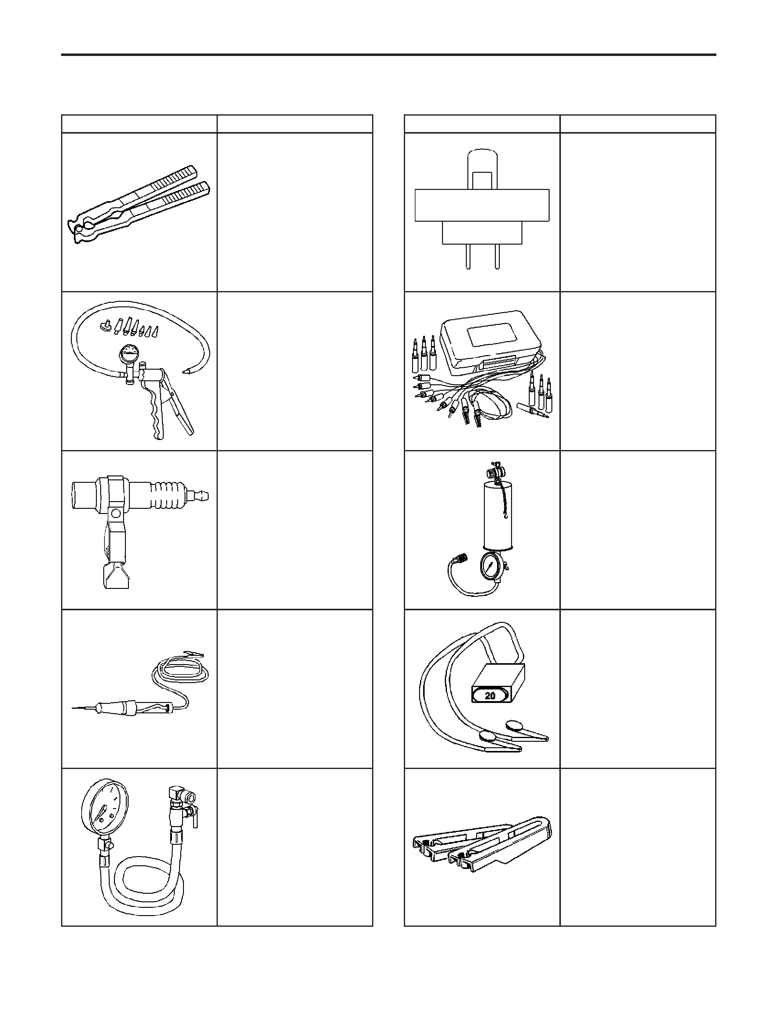
Special Tools and Equipment
Illustration Tool Number/Description
82243
J 22610
Service Boot Clamp
5386
J 23738-A
Vacuum Pump
5381
J 26792
Spark Tester
5382
J 34142-B
Test Light
5389
J 34730-1A
Fuel Pressure Gauge
Illustration Tool Number/Description
5390
J 34730-2C
Injector Test Light (EFI Lite)
8917
J 35616-A
Connector Test Adapter Kit
821470
J 35800-A
Fuel Injector Cleaner
1025
J 36169–A
Fused Jumper Wire
12366
J 37088-A
Fuel Line Quick Connect
Separator
EngineControls-6.0LEngine
Illustration Tool Number/Description
13541
J 37287
Inlet and Return Fuel Line
Shut off Adapters
5380
J 39021
Fuel Injector Coil/Balance
Tester
3430
J 39200
Digital Multimeter
16891
J 39765
Fuel Sender Lock Nut
Wrench
825000
J 41413–200
Evaporative Emissions
System Tester (EEST)
Illustration Tool Number/Description
829182
J 41413–SPT
High Intensity White Light
1161160
J 41413–306
EVAP Plug
1161161
J 41413–307
EVAP Plug
1174862
J 41413–311
EVAP Plug
829198
J 41413–VLV
EVAP Service Port Vent
Fitting
EngineEngineControls-6.0L
Illustration Tool Number/Description
254302
J 41415–40
Fuel Tank Cap Adapter
69758
J 41416
Ultrasonic Leak Detector
208072
J 42236-A
Serial Data Link Test
624560
J 42598
Vehicle Data Recorder
Illustration Tool Number/Description
696431
J 43244
Relay Puller Pliers
677554
J 44175
Fuel Composition Tester
793709
J 45004
Fuel Tank Drain Hose
50062
Tech 2 Kit
7000081
EngineControls-6.0LEngine