
Charging System – HSV - Gen IV V8 Page 6D4-1–1
Page 6D4-1–1
Section 6D4-1
Charging System – HSV - Gen IV V8
ATTENTION
Before performing any Service Operation or other procedure described in this Section, refer to Section 00
Warnings, Cautions and Notes for correct workshop practices with regard to safety and/or property damage.
1 General Information ...............................................................................................................................2
1.1 Operation................................................................................................................................................................ 5
Circuit Overview..................................................................................................................................................... 5
Warning Lamp Conditions .................................................................................................................................... 5
Circuit Diagram...................................................................................................................................................... 6
2 Service Operations.................................................................................................................................7
2.1 Safety Precautions................................................................................................................................................. 7
2.2 Maintenance and On-vehicle Testing................................................................................................................... 8
Regulating Voltage Test........................................................................................................................................ 8
3 Major Service Operations......................................................................................................................9
3.1 Generator................................................................................................................................................................ 9
Remove................................................................................................................................................................... 9
Disassemble......................................................................................................................................................... 11
Reassemble.......................................................................................................................................................... 14
Reinstall................................................................................................................................................................ 16
4 Diagnosis ..............................................................................................................................................17
5 Specifications.......................................................................................................................................18
6 Torque Wrench Specifications............................................................................................................19

Charging System – HSV - Gen IV V8 Page 6D4-1–2
Page 6D4-1–2
1 General Information
This section provides details on the Charg in g system fitted to the MY 2004 HSV VZ Series vehicles
The GEN IV V8 engine is fitted with a Mitsubishi 1 40 amp generator. This generator is mounted on the lower, left-hand
side of the engine. It has an internall y mounted regulator; a single lower mounting lug and no external cooling fans. For
information about the generator mounting bracket removal and installation,
refer to Section 6A4 Engine Mechanical – GEN IV V8.
The generator is three phase, incorporating a rotor with six pole pairs and two (internal) cooling fans; one on the drive
end and one on the slip-ring end. The rotor is supported by ball bearing races in both the drive a nd slip-ring end
housings. The stator surround s the rotor and has a three-phase delta connected out put winding on a ring shaped
lamination pack.
The output of the stator winding is rectified by six diodes within the slip-ring end housing. Excitation current is supplied to
the rotor field coil via the voltage regulat or, the brush es and slip-rings. The electronic voltage regulator requires no
adjustment in service.
This generator has two external connections (refer to Figures 6D4-1-1 and 6D4-1-2):
• B+ lead to the battery positive terminal
• L lead to the 3kΩ resistor (50mA max)
• ground connection (via the installation bolts)
Charging System – HSV - Gen IV V8 Page 6D4-1–3
Page 6D4-1–3
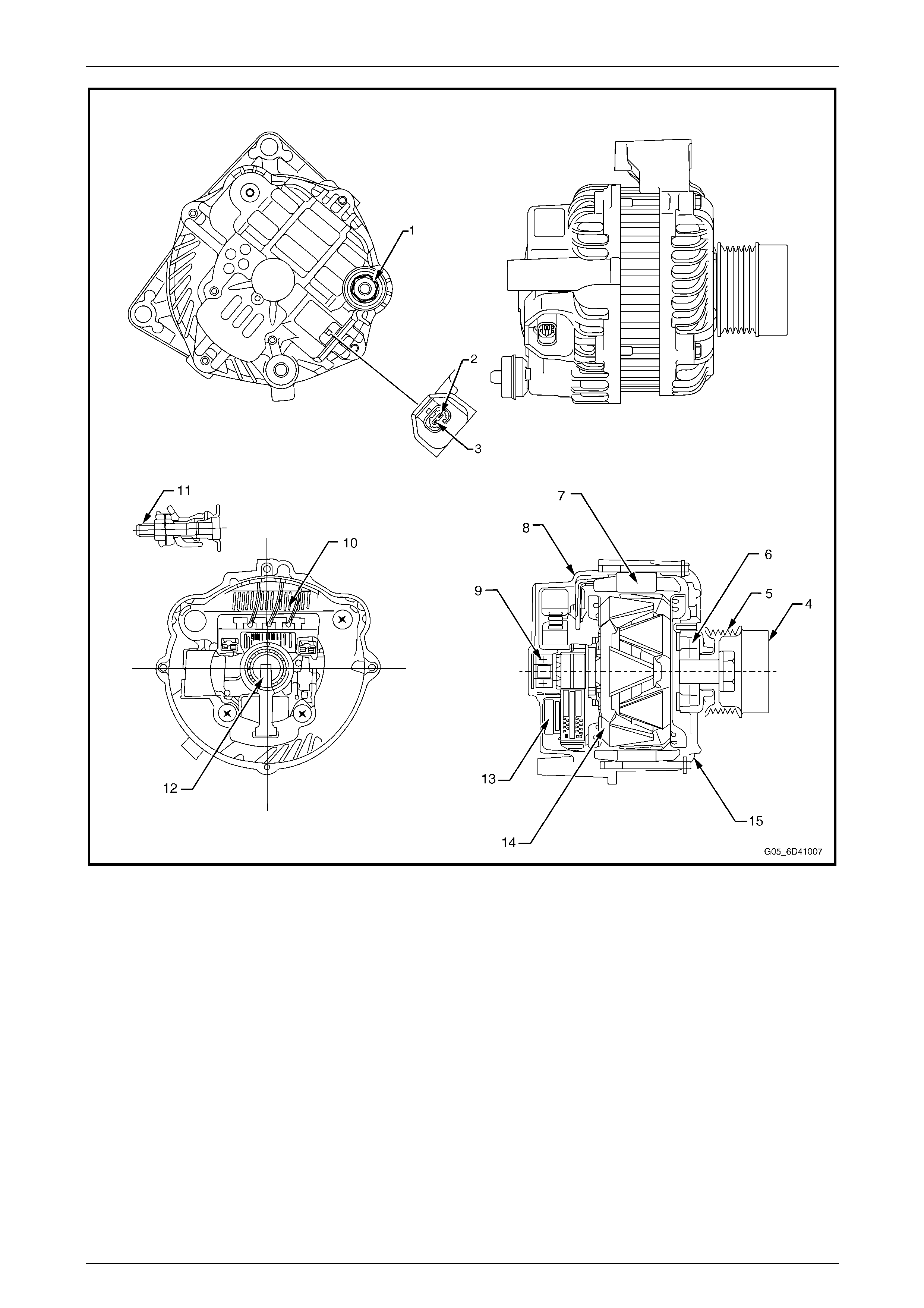
Figure 6D4-1 – 1
Legend
1 Battery B+ Terminal
2 L Terminal
3 S Terminal
4 De-coupler Pulley
5 Pulley
6 Bearing
7 Stator
8 Rear Bracket
9 Bearing
10 Rectifier
11 B+ Terminal Bolt
12 Brushes
13 IC Regulator
14 Rotor
15 Front Bracket
Charging System – HSV - Gen IV V8 Page 6D4-1–4
Page 6D4-1–4
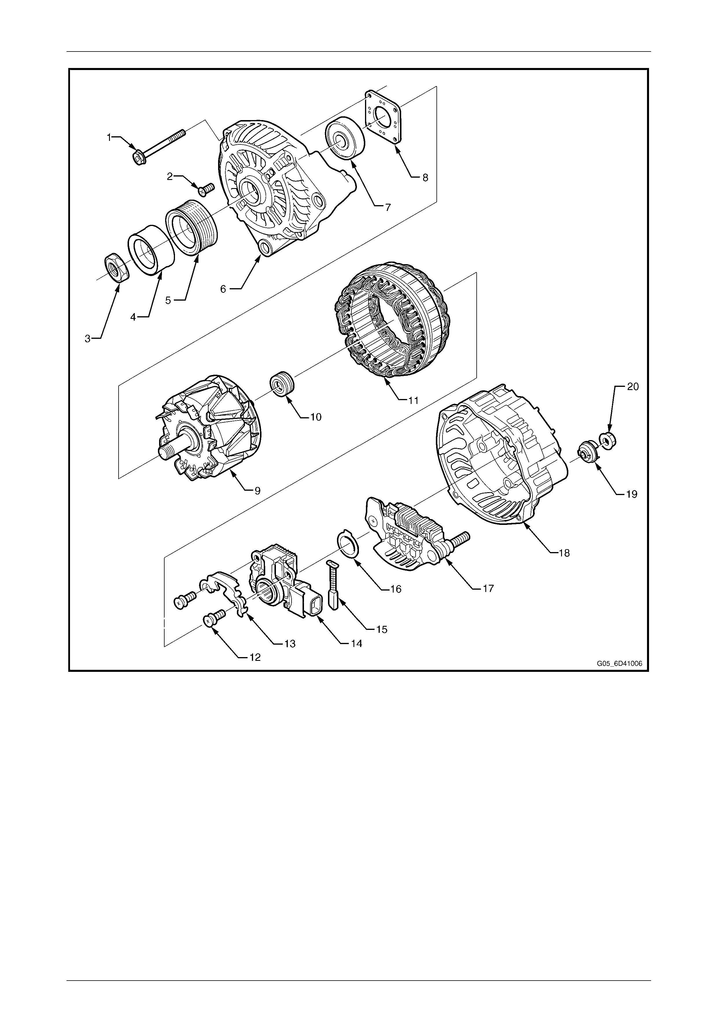
Figure 6D4-1 – 2
Legend
1 Through-bolt
2 Bearing Retaining Plate Screw
3 Nut
4 De-coupler Pulley
5 Drive Pulley
6 Front Bracket Assembly
7 Front Bearing
8 Bearing Retaining Plate
9 Rotor
10 Slip-ring End Bearing
11 Stator
12 Regulator and Brush Screws
13 Brush Retaining Plate
14 Regulator
15 Brush
16 Thrust Washer
17 Rectifier Assembly
18 Rear Bracket Assembly
19 Terminal Cover Bush
20 Nut

Charging System – HSV - Gen IV V8 Page 6D4-1–5
Page 6D4-1–5
1.1 Operation
Circuit Overview
With the ignition switched on, current is supplied via resistance to the L terminal of the regulator with a maximum sinking
current of 50mA. This allows current to flow (within the regulator) from the generator B+ terminal to the brushes and rotor
winding.
The current in the rotor winding creates magnetic fields between adjacent rotor poles. As the rotor spins, the stator
windings cut through this field at right angles and induce voltage. As the speed increases, this induced voltage increases.
Current then flows through the three-phase diode bridge in the rectifier to convert the AC voltage to DC. This is supplied
to the B+ output and then to the battery.
The regulator B terminal monitors the system voltage. When this voltage reconnects approximately 14.5 volts, the
regulator opens the circuit through the rotor winding, causing the generator output voltage to drop. When the regulator
senses a voltage below a preset value, of th e B T erminal, the regulator closes the circuit through the rotor winding and
voltage to the battery again increases. This cycle repeats very rapidly.
Current does not flow through the rotor winding when the engine is cranking.
Warning Lamp Conditions
The regulator L terminal remains low when it detects a fault condition in the generator or the external circuits. The
terminal remains low until all faults are repaired.
Fault conditions include the fo llowing:
• Open circuit or excessive voltage drop in the B+ cable.
• Open circuit in the generator phase conn ection.
• Overcharging of the battery.
• Short circuit in the regulator output stage.
• Open circuit in the rotor winding.
• Poor contact between the rectifier and the regulator.
• Poor contact between the batter y terminals and ca bles.
Charging System – HSV - Gen IV V8 Page 6D4-1–6
Page 6D4-1–6
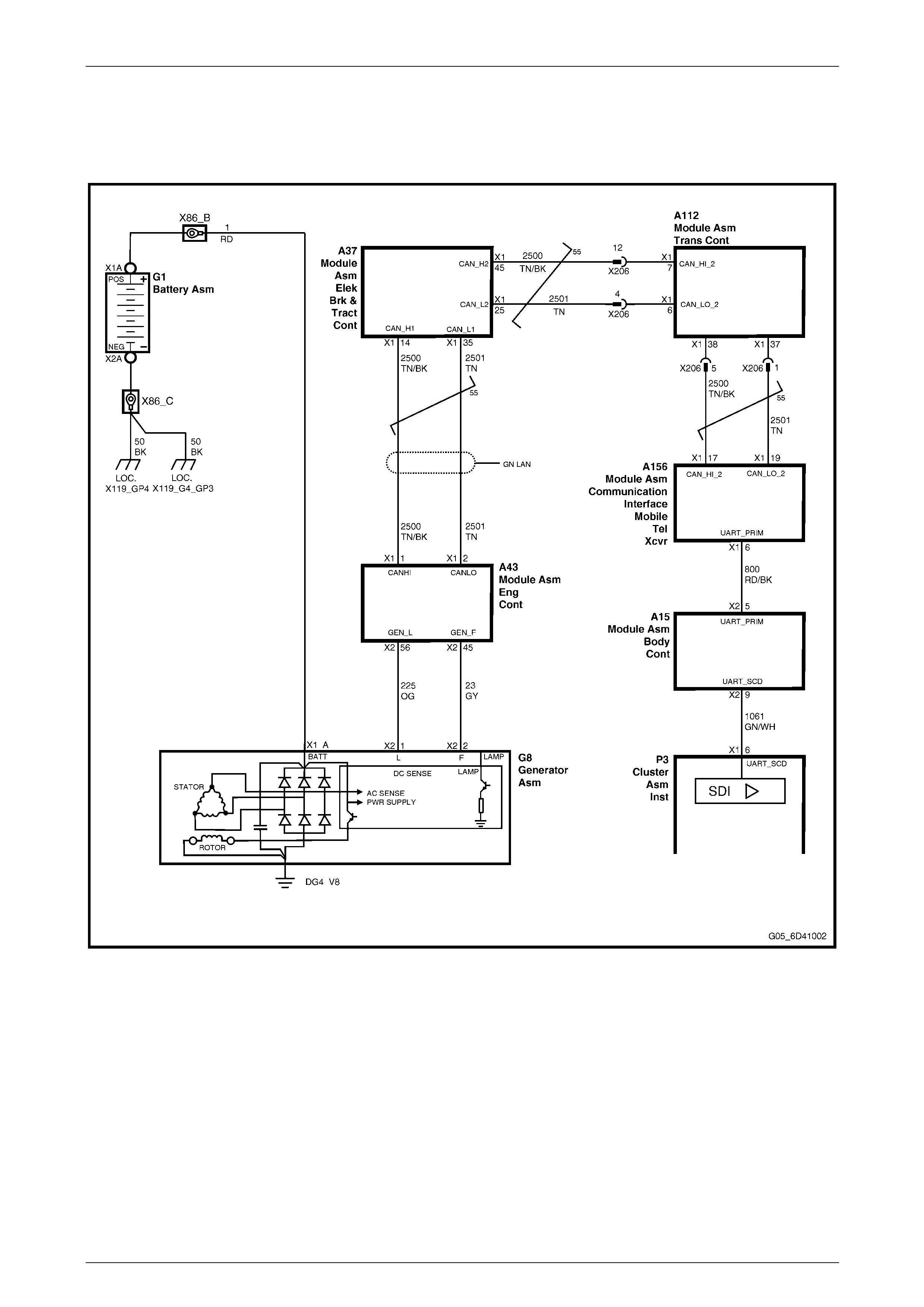
Circuit Diagram
Figure 6D4-1 – 3 shows the charging circuit as applicable to MY 2004 HSV VZ vehicles. Use this diagram to assist with
charging circuit fault diagnosis
Figure 6D4-1 – 3
Charging System – HSV - Gen IV V8 Page 6D4-1–7
Page 6D4-1–7
2 Service Operations
2.1 Safety Precautions
Observe the following precautions. Failure to observe these precautions will result in serious damage to the generator:
• Apply the generator and voltage regulator only on a negativ e ground system.
• When installing a batter y, fit the positive (+) cable to the battery before fitting the negative cable.
• When a slave battery is used for starting purposes, ensure that both batteries are connected in parallel. That is,
positive terminals connected and neg ative terminals connected.
• Only use jumper leads that have surge protection.
• Disconnect both battery cables when charging the battery. This isolates the generator from the batter y and from the
external chargi ng equipment.
• Do not operate the generator within an o pen circuit or without a battery in the circuit.
• Do not disconnect the battery while the generator is runn ing.
• Do not attempt to polarise the generator.
• Always ensure that the L terminal turns on when the ignition is switched to the On position.
• Do not connect the L terminal of the generator to 12 volts (the battery or ignition circuits). This damages the L
terminal circuit.
• Some battery powered timing lights can produce high transient voltages when connected or disconnected. Only
disconnect or connect timing lights when the engine is switched off.
Ensure the L terminal h as a maximum sinking
current of 50m A.
Charging System – HSV - Gen IV V8 Page 6D4-1–8
Page 6D4-1–8
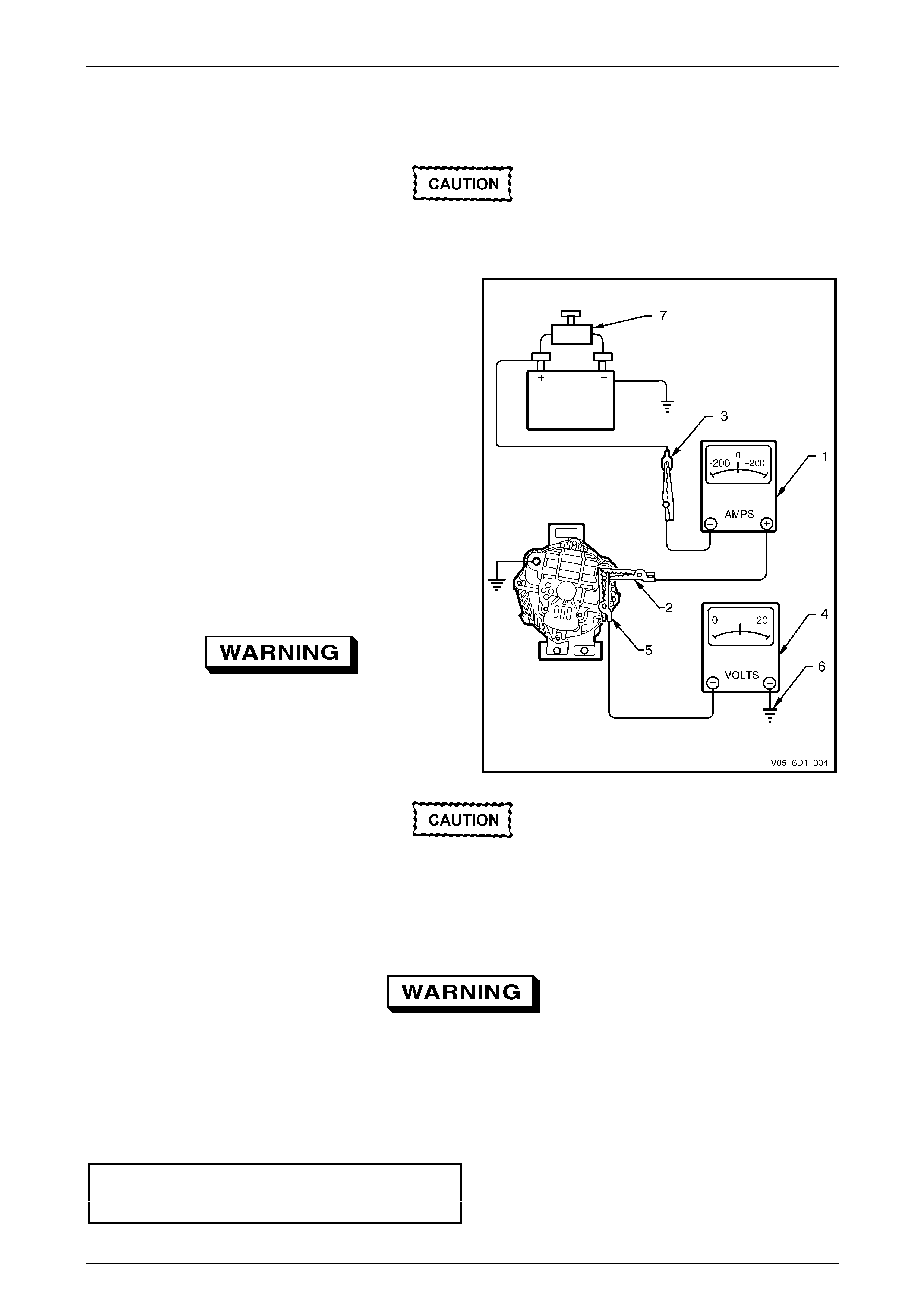
2.2 Maintenance and On-vehicle Testing
The generator L Terminal connection is
necessary for initial field excitatio n in additio n
to indicating that the gen erato r is charging.
Regulating Voltage Test
1 Turn the ignition off and turn off all electrical
equipment.
2 Refer to Section 00 Warnings, Cautio ns And Notes
before disconnecting the batter y.
3 Disconnect the battery ground cable from the battery.
4 Disconnect the generator positive lead (red wire) from
the generator B+ terminal.
5 Connect the positive lead of an ammeter (1) to the
generator B+ terminal (2).
NOTE:
Ensure that the ammeter is set to measure at
least 140 amps.
6 Connect the negative ammeter lead to the
disconnected gener ator positive lead (3).
7 Connect the positive lead of a voltmeter (4) to the
generator B+ terminal (5).
Set the voltmeter scale to 0 – 20 volts.
8 Connect the negative voltmeter lead to a goo d
ground connection on the gen erator housing (6).
Figure 6D4-1 – 4
Insulate the terminal of the generator positive
lead (red wire) to prevent contact with any
metal part of the vehicle. If this occurs,
damage to the charging circuit results when
the battery is reconnected.
9 Reconnect the battery ground cable.
10 Fit a loading device across the battery terminals, e.g. an adjustable carbon pile.
The loading device must have a power
consumption rating of at least 1000 watts.
11 Record the voltmeter reading before starting the engine. (This reading should increase when the engine is running,
indicating generator output.)
12 Start the engine.
13 Increase the engine speed a nd adjust the load (using the ammeter reading) as outli ned in the chart below.
14 Check the generator output voltage (voltmeter reading) against the specification.
Engine RPM............................................................ 1300
Load.............................................................5 – 10 amps
Voltmeter reading..................................13.8 – 14.5 volts
Charging System – HSV - Gen IV V8 Page 6D4-1–9
Page 6D4-1–9
3 Major Service Operations
3.1 Generator
Remove
The generator is in close proximity to an
exhaust manifold. Allow the engine to cool
before removing the generator
1 Refer to Section 00 Warnings, Cautio ns And Notes before disconnecting the batter y.
2 Disconnect the battery ground lead.
3 Remove the radiator shroud as follows. Using a
fine, flat-blade screwdriver, prise the centre pin
of the retainer (1) upward and remove the
retainer, five places.
4 Lift up the upper radiator shroud (2) to
disengage the retaining cl ip (3) and remove the
shroud.
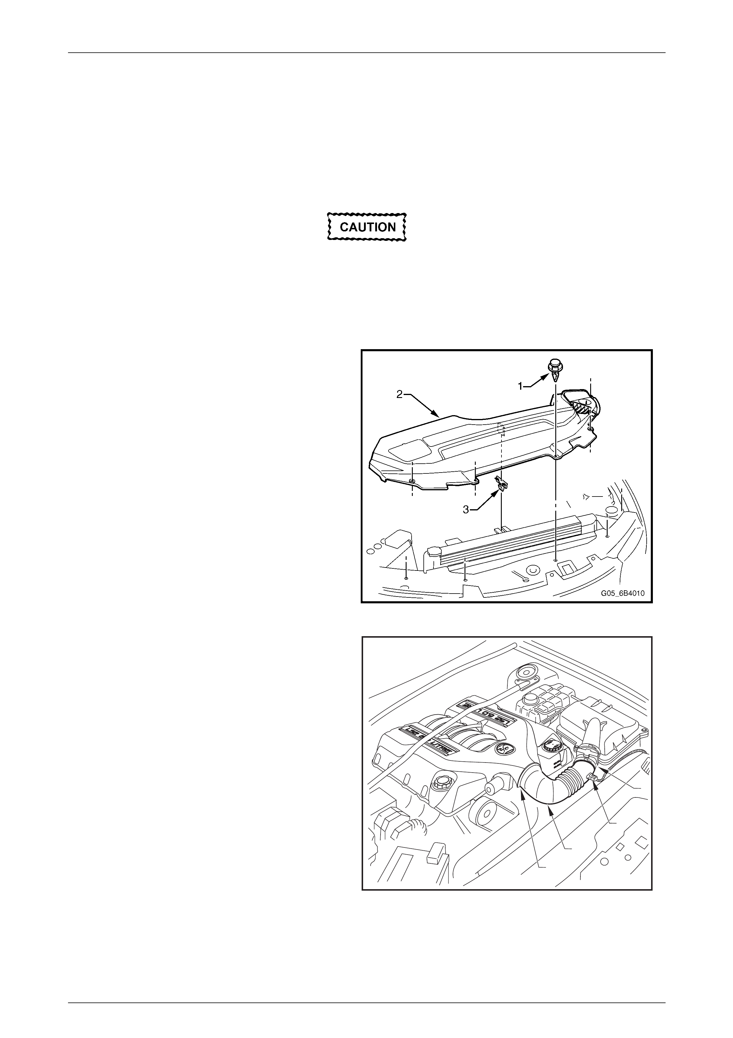
Figure 6D4-1 – 5
5 Remove the crankcase ventilation tube (1) from
the air intake duct (2).
6 Disconnect the Mass Air Flow (MAF) sensor
wiring connector (3).
7 Loosen the two intake duct clam ps, one at the
throttle body and the other at the air clean er
connection and remove the intake duct and MAF
as an assembly.
1
2
3
4
Figure 6D4-1 – 6
Charging System – HSV - Gen IV V8 Page 6D4-1–10
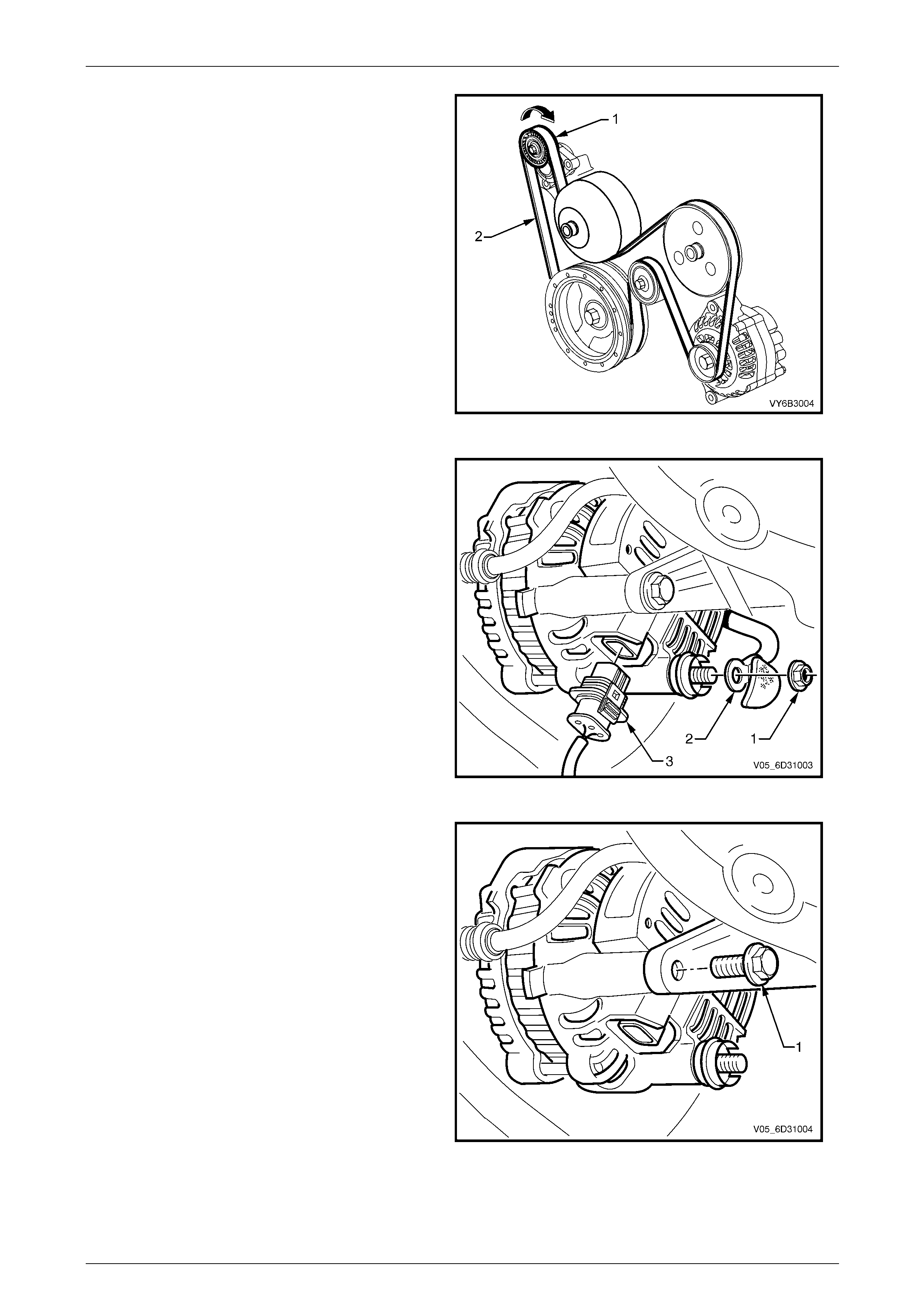
Page 6D4-1–10
8 Using a 15 mm ring spanner, rotate the en gine
accessory drive belt tensioner (1) in the direction
indicated, to reduce belt tension.
9 While holding the tensi on er in the reduced
tension position, remove the accessory drive
belt from the generator drive pulley, taking note
of the belt routing Turn the assembly and
remove the drive belt from the generator dr ive
pulley.
10 Release the drive belt tensioner.
11 Remove the power steering pump and reservoir.
Refer to Section 9 Steering.
Figure 6D4-1 – 7
12 Pull the battery harness cap back from the
B+ terminal and remove the nut (1) and positive
lead (2).
13 Press the connector retainer tab to release t he
connector (3) from the generator assembly.
14 Disconnect the generator connector.
Figure 6D4-1 – 8
15 Remove the bolt (1) from the rear-mounting
bracket of the generator.
Figure 6D4-1 – 9
Charging System – HSV - Gen IV V8 Page 6D4-1–11
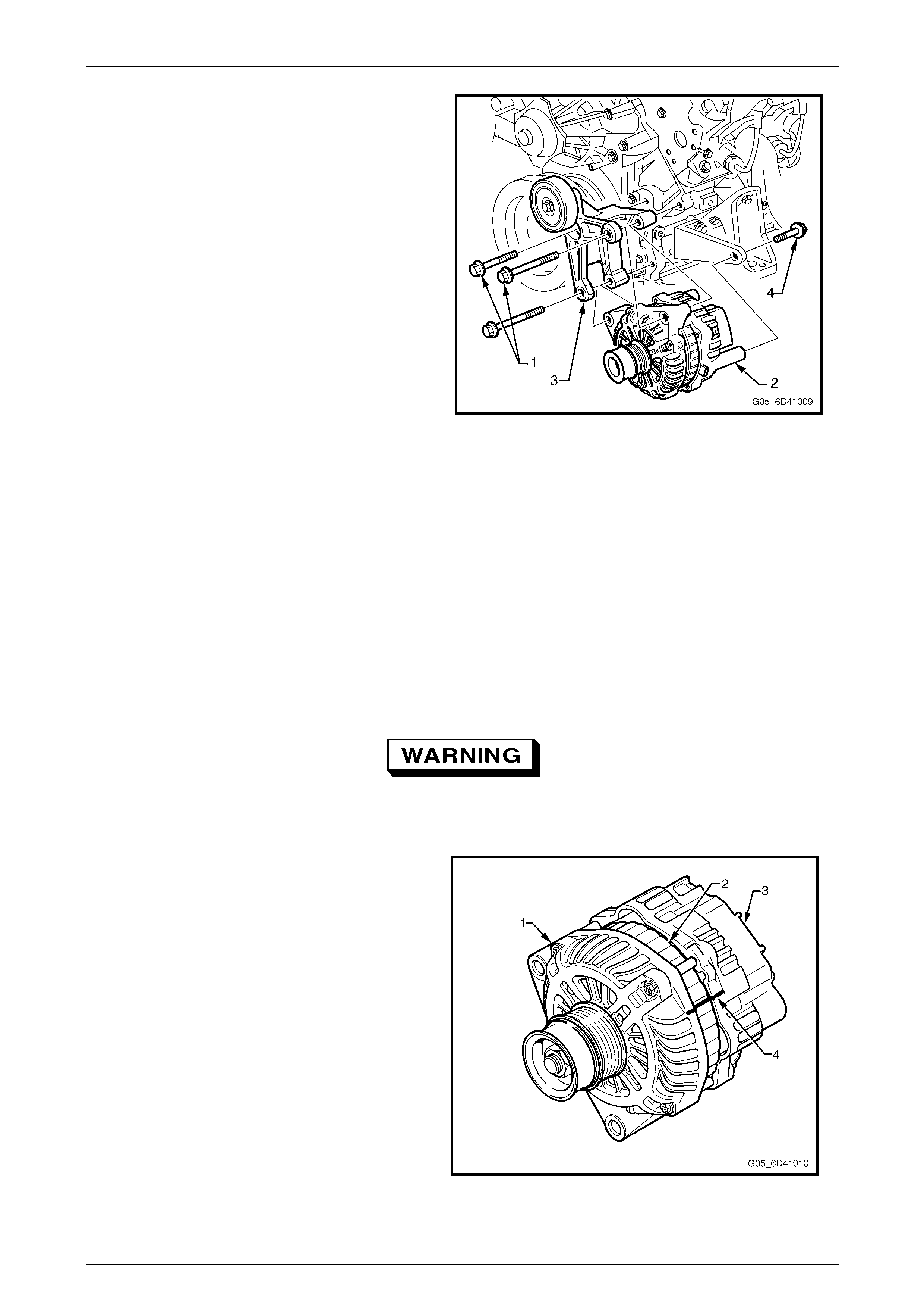
Page 6D4-1–11
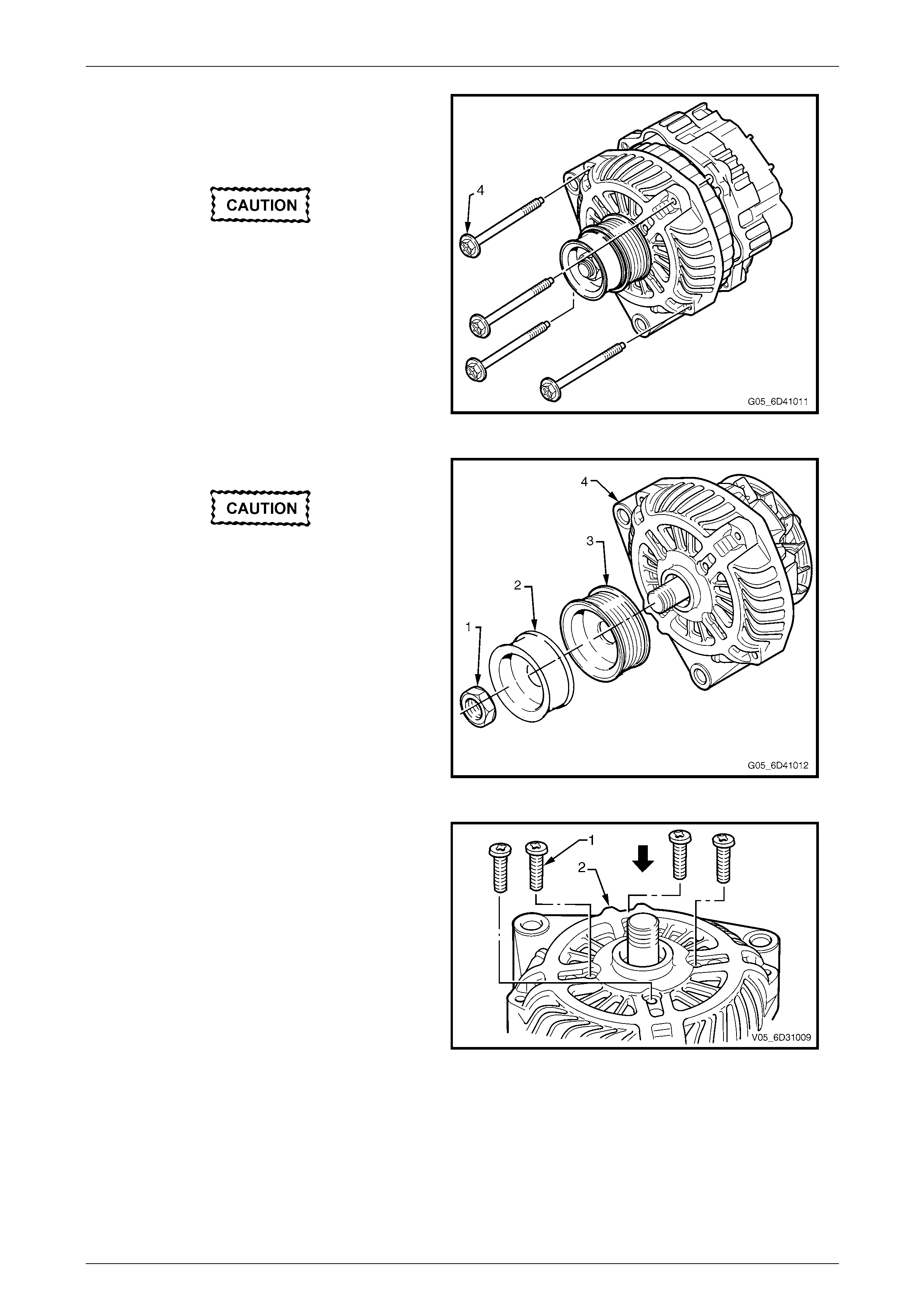
16 Remove the three bolts (1) securing the
generator (2) and mounting bracket (3) to the
engine.
NOTE
Item 4 in Figure 6D4-1 – 10 is the bolt
removed in Step 15.
17 Separate the generator from the mountin g
bracket and lower the generat or down onto the
stabiliser bar.
18 Remove the mounting bracke t and idler pulley
assembly.
19 Lift the generator up and out from between the
engine and the radiator.
Figure 6D4-1 – 10
Disassemble
Precautions
When testing the generator for faulty components, ensure that:
• the RMS output of the AC type tester for checking the rectifier diodes does not exceed 12.0 volts
• the stator is disconnected before testing the diodes
• all diodes have the same Z en er voltage (when testing the diode breakdown voltages)
• voltage does not exceed 110 volts for a series test lamp when testing the insulation on the rotor and stator
• the rectifier is disconnected from the stator prior to testing the stator.
Due to the very low resistance value of the
stator winding, accurate readings might not
be achieved using a conventional ohmmeter.
1 Using a permanent marking pen, mark the
relative positions of the front-end housing (1),
the stator frame (2) and the rear-end housing
(3), for example, (4).
Figure 6D4-1 – 11
Charging System – HSV - Gen IV V8 Page 6D4-1–12
Page 6D4-1–12
2 Remove the four through-bolts (4).
3 Carefully separate the rear-end housing and
stator (as an assembly) from the rotor and
front-end housing.
Do not lever against, or put strain on,
the stator windings.
Figure 6D4-1 – 12
4 Clamp the rotor in a vice that has soft-jaws.
Do not distort or damage the rotor
poles.
5 Remove the drive pulley attaching nut (1).
6 Remove the De-coupler pulle y (2).
7 Remove the drive pulle y (3).
8 Remove the front housing (4) .
Figure 6D4-1 – 13
9 Remove the four screws (1) that secure the
bearing retaini ng plate to front housing.
10 Press the bearing from the front bracket (2).
Figure 6D4-1 – 14
Charging System – HSV - Gen IV V8 Page 6D4-1–13
Page 6D4-1–13
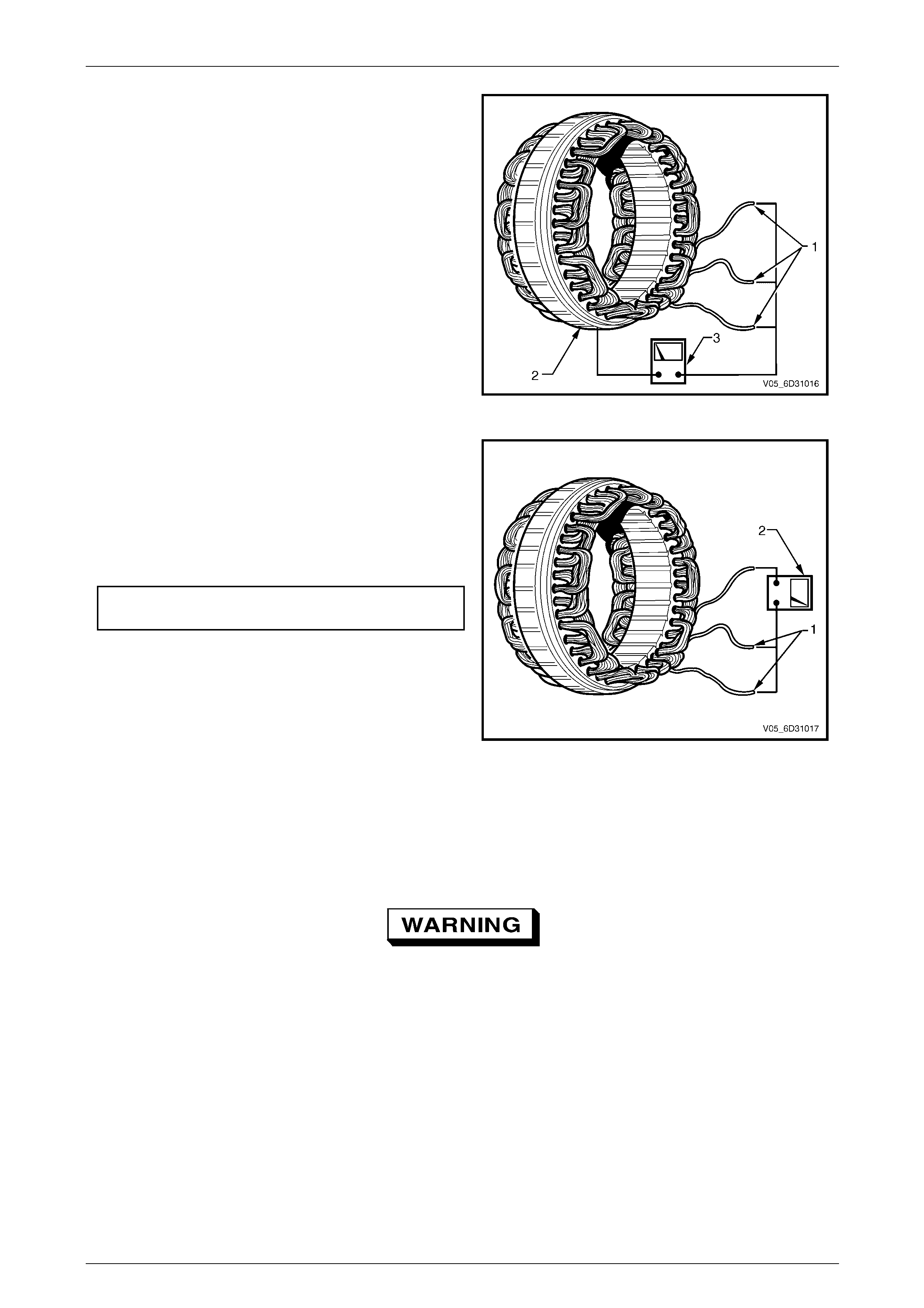
Check the rotor
1 Clean any dirt or particles from the rotor with
compressed air and / or a clean cloth.
2 Test the rotor insulation between the slip-rings (1)
and rotor shaft (2) using an insulation tester (3) or a
series test lamp up to 110 volts.
3 Check that the insulation tester indic ates an o pen
circuit (greater than 1 Megohm) and a test light does
not glow.
4 Replace the rotor if an open circuit does not exist.
Figure 6D4-1 – 15
5 Test the rotor for an open circuit by connecting the
ohmmeter (1) probes across the slip-rings (2).
NOTE
The rotor winding r esistance value might be t oo
small to measure with a conventional meter.
Rotor winding resistance @ 20°C.....................2.1 ohms
6 Replace the rotor if the rotor winding has an open
circuit.
7 Check the slip-rings for wear or damage.
8 Machine the slip-rings if they are worn, scored,
damaged or out-of-round beyond specifications.
Extreme care must be exercised when
machining the slip-rings to avoid the turning
tool fouling the rear rotor cooling fan.
9 Check that the slip-rings are within specifications
(especially after machining).
10 Replace the rotor if the slip-ring is outside of the
specification.
Slip-ring minimum outer diameter..................... 22.1 mm
Figure 6D4-1 – 16
Charging System – HSV - Gen IV V8 Page 6D4-1–14
Page 6D4-1–14
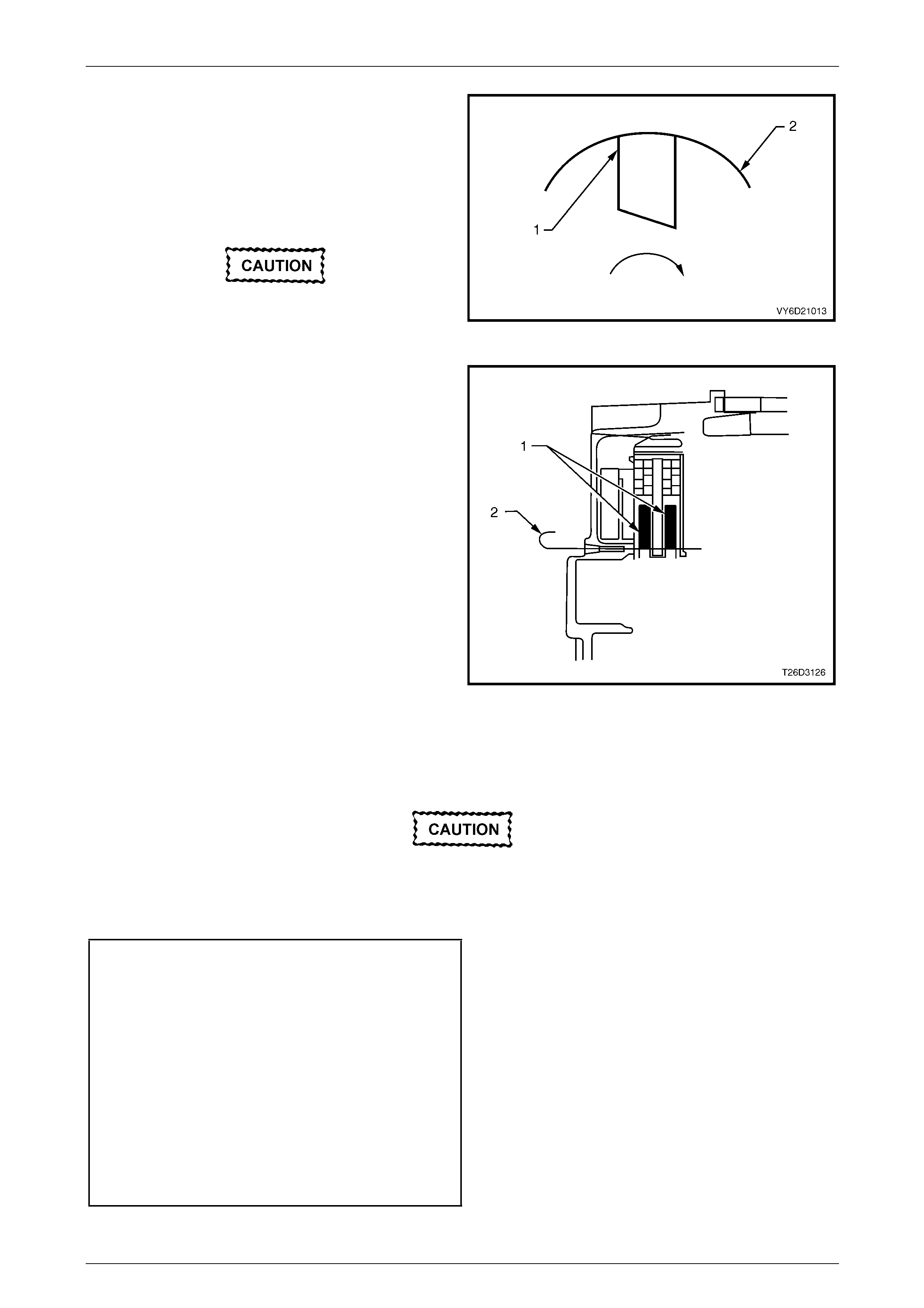
Check the stator
1 Inspect the stator for damage, loose connections or
discoloured windings.
2 Replace the stator if necessary.
3 Test the stator insulation between any stator lead (1)
and the stator frame (2). Use a powered test-lamp
rated up to 40 volts, an ohmmeter (3) or an insulation
tester
4 Check that the test-lamp does not glow and the
ohmmeter or insulation tester indicates an open
circuit (greater than 1 Megohm).
5 Replace the stator if an open circuit do es not exist.
Figure 6D4-1 – 17
6 Test the stator winding circuits by connecting any two
stator leads (1) with an ohmmeter (2).
7 Check that the ohmmeter does not register a
significant resistance.
8 Repeat this test between the remainin g stator leads.
9 Replace the stator if it is outside the specification.
Stator windings
resistance @20°C.......................................... 0.098 ohm
Figure 6D4-1 – 18
Reassemble
Refer to Figure 6D4-1 – 2 for identification of components.
1 Reassemble the generator in the reverse ord er of the disassembly procedure.
It is important that all parts are thoroughly
dried before assembly, taking care not to
breathe any vapours in.
2 Check the bearing box for oil.
3 Completely remove any oil on the bearing box to prevent bearing creep.
NOTE
Do not lubricate the bearings; they are
pre-lubricated.
NOTE
Do not apply grease to rotor bearings that have
resin bands.
Charging System – HSV - Gen IV V8 Page 6D4-1–15
Page 6D4-1–15
4 Position each brush (1) in the brush holder (2) as
indicated in Figure 6D4-1 – 20.
5 Ensure that the new brushes extend at least 13 mm
from the brush holder.
6 Solder the brushes, using high temperature solder
(melting point 230°C) and a 180 – 270 watt soldering
iron.
Do not use excessive heat as this can
damage rectifier.
Figure 6D4-1 – 19
7 Install the rotor and front bracket assembly in the
follows.
a Push the brushes (1) fully back into the brus h
holder in the rear bracket assembly.
b Insert a suitable wire (2) from the outside of the
rear bracket assembly to hold the brushes in the
retracted position.
c Carefully heat the area around the rear bracket
bearing box to 50 – 60°C. This aids in assembly and
avoids damaging the tight fitting components.
8 Install the rotor into the rear bracket assembly.
9 Align the front bracket, stator frame and rear bracket
accurately. Use the markings made prior to
disassembly.
NOTE
When removing the wire, listen for both brushes
to click into position on the slip-ring.
10 Remove the wire.
Figure 6D4-1 – 20
11 After assembly, rotate the pulley slowly by hand to ensure that the rotor turns smoothly.
Do not over-tighten the B+ terminal nut. This
action will damage the insu latin g washer.
12 Tighten all fasteners to the correct torque specifications.
Drive pulley attaching nut
torque specification....................................99 – 137 N.m
Through-bolt
torque specification....................................3.5 – 5.3 N.m
Bearing retainer screw
torque specification....................................2.9 – 4.9 N.m
Brush holder retaining screw
torque specification....................................2.9 – 4.9 N.m
Rectifier retaining screw
torque specification....................................2.9 – 4.9 N.m
B+ Terminal nut
torque specification................................12.8 – 18.6 N.m
Charging System – HSV - Gen IV V8 Page 6D4-1–16
Page 6D4-1–16
Reinstall
1 Install the generator by following the removal procedure in reverse order.
2 Tighten the follo wing fasten ers to the correct torque:
a Mounting bracket bolt.
b Generator retaining bolts.
c Battery harness to B+ terminal nut (positive lead to B+ terminal).
Rear mounting bracket bolt
torque specification......................................40 – 60 N.m
Generator and mounting bracket bolt
torque specification......................................40 – 60 N.m
Idler pulley mounting brack et bolt
torque specification......................................20 – 34 N.m
Battery harness to B+ Terminal nut
torque specification..................................7.1 – 13.3 N.m
Charging System – HSV - Gen IV V8 Page 6D4-1–17
Page 6D4-1–17
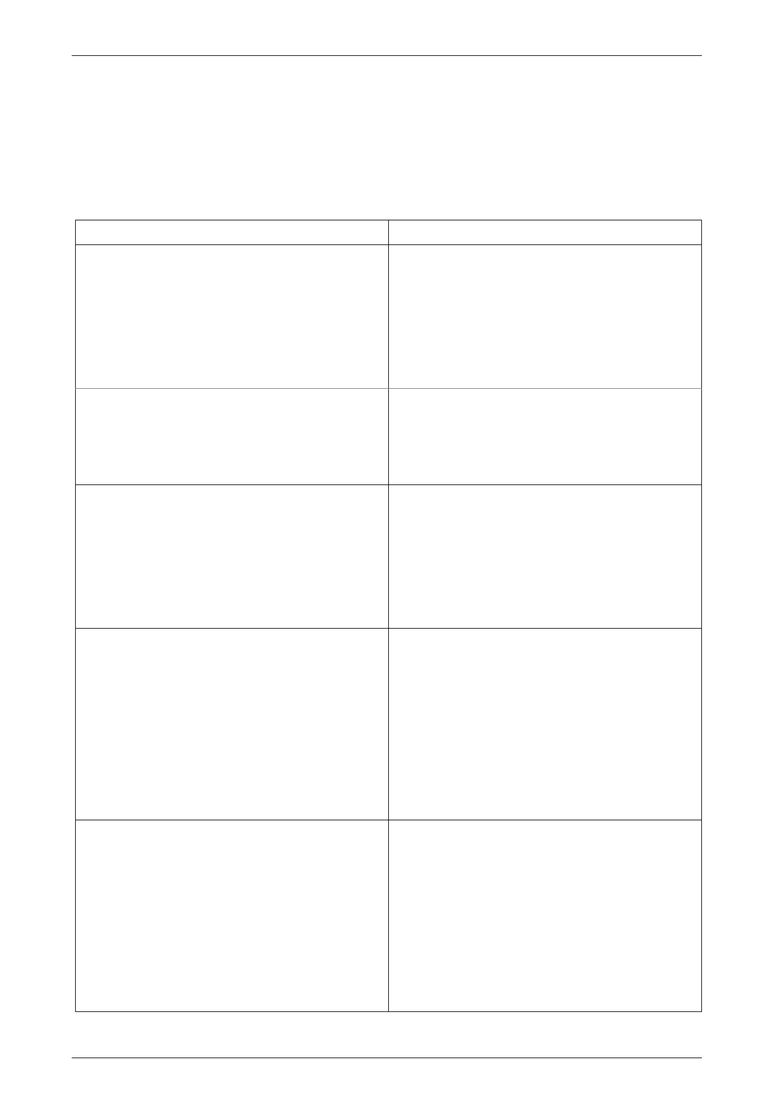
4 Diagnosis
Reference to following information will assist when diagnosing charging circuit faults:
• For battery testing, refer to Section 12A Battery.
• For circuit diagram details, refer to Figure 6D4-1 – 3.
• For electrical component locations, refer to Section 12P Wiring Diagrams .
Condition Potential Causes
Undercharged Battery Defective battery
Loose connection in charging system
Corroded connections in charging circuit
Defective wiring
Faulty generator
Faulty voltage regulator
Overcharged Battery Shorted battery cell
Faulty voltage regulator
Short circuit in rotor winding
Voltage drop in sense wire
Faulty Indicator Lamp Operation (lamp does not glow) Burnt out LED
Defective cluster connection
Defective wiring
Defective rectifier
Defective regulator
Defective ECM
Faulty Indicator Lamp Operation (lamp remains on) Negative diode failure
Defective voltage regulator
Faulty generator
Defective ECM
B+ cable off or broken
S cable off or broken
Battery overcharged
Open circuit in rotor winding
Noisy Generator Operation Normal magnetic hum
Badly discharg ed battery
Generator mounting brackets loose or bolts loose
Worn or frayed drive belt
Worn bearings
Loose drive pulley attaching nut
Open or shorted diodes
Open or shorted stator winding

Charging System – HSV - Gen IV V8 Page 6D4-1–18
Page 6D4-1–18
5 Specifications
Voltage Regulator Setting...............................................................................14.2 – 14.8 volts
Stator Winding Resistance @ 20°C.......................................................................0.098 ohms
Rotor Winding Resistance @ 20°C............................................................................2.1 ohms

Charging System – HSV - Gen IV V8 Page 6D4-1–19
Page 6D4-1–19
6 Torque Wrench Specifications
...........................................................................................................................................N.m
Bearing Retainer Screw..............................................................................................2.9 – 4.9
Brush Holder Retaining Screw....................................................................................2.9 – 4.9
Rectifier Retaining Screw ...........................................................................................2.9 – 4.9