
Powertrain Interface Module – HSV – Gen IV V8 Page 6E4–1
Page 6E4–1
Section 6E4
Powertrain Interface Module – HSV – Gen IV V8
ATTENTION
Before performing any service operation or other procedure described in this Section, refer to Section 00
Warnings, Cautions and Notes for correct workshop practices with regard to safety and/or property damage.
1 General Information ...............................................................................................................................6
1.1 General Description............................................................................................................................................... 6
Serial Data Communication .................................................................................................................................. 6
Bus..................................................................................................................................................................... 6
Serial Data ......................................................................................................................................................... 7
Serial Data Communication Protocols................................................................................................................ 7
Serial Data Layout.................................................................................................................................................. 8
2 Component Location .............................................................................................................................9
2.1 Engine Compartment............................................................................................................................................. 9
2.2 Interior .................................................................................................................................................................. 10
3 Component Description and Operation.............................................................................................11
3.1 Powertrain Interface Module............................................................................................................................... 11
Communication Gateway.................................................................................................................................... 11
3.2 Powertrain Interface Module Gateway Components ........................................................................................ 12
Engine Control Module........................................................................................................................................ 12
ABS-TCS Electronic Control Unit....................................................................................................................... 12
Body Control Module........................................................................................................................................... 12
Automatic Transmission Control Module.......................................................................................................... 13
3.3 Powertrain Interface Module Direct Input Switches.......................................................................................... 14
Traction Control System Switch......................................................................................................................... 14
Cruise Control Switch ......................................................................................................................................... 14
4 Diagnostics...........................................................................................................................................15
4.1 Diagnostic General Descriptions........................................................................................................................ 15
Diagnostic Trouble Code (DTC) Tables ............................................................................................................. 15
Multiple DTCs................................................................................................................................................... 15
Diagnostic Trouble Codes (DTCs)...................................................................................................................... 16
Status of DTCs................................................................................................................................................. 16
Conditions for Clearing DTCs........................................................................................................................... 16
Tech 2 PIM Diagnostic Tests............................................................................................................................... 16
Tech 2 Limitations............................................................................................................................................ 16
Tech 2 Intermittent Fault Tests......................................................................................................................... 16
Tech 2 Data List............................................................................................................................................... 17
5 Powertrain Interface Module Diagnostic Starting Point...................................................................18
5.1 Diagnostic Requirements, Precautions and Preliminary Checks.................................................................... 18
Basic Knowledge Required................................................................................................................................. 18
Basic Diagnostic Tools Required....................................................................................................................... 18
Diagnostic Precautions....................................................................................................................................... 19
Preliminary Checks.............................................................................................................................................. 19
5.2 Main Diagnostic Table......................................................................................................................................... 20
5.3 Powertrain Interface Module – Module Presence Check Failure Diagnostic Table........................................ 22

Powertrain Interface Module – HSV – Gen IV V8 Page 6E4–2
Page 6E4–2
6 Intermittent Fault Conditions..............................................................................................................23
6.1 Intermittent Conditions Diagnostic Table.......................................................................................................... 23
Description........................................................................................................................................................... 23
Diagnostic Table.................................................................................................................................................. 23
7 DTC Tables............................................................................................................................................25
7.1 DTC B1000, B1009, B1013 or B1014 – PIM Internal Fault................................................................................. 25
Circuit Description............................................................................................................................................... 25
Additional Information......................................................................................................................................... 25
Conditions for Running the DTC B1000, B1009, B1013 or B1014.................................................................... 25
Conditions for Setting the DTCs......................................................................................................................... 25
Action Taken When the DTCs Set ...................................................................................................................... 25
Conditions for Clearing DTCs............................................................................................................................. 25
Test Description................................................................................................................................................... 25
DTC B1000, B1009, B1013 or B1014 Diagnostic Table..................................................................................... 26
7.2 DTC U1304 – Lost Communications with UART System............................................................................... ... 27
Circuit Description............................................................................................................................................... 27
Additional Information......................................................................................................................................... 27
Conditions for Running the DTC........................................................................................................................ 27
Conditions for Setting the DTC........................................................................................................................... 27
Action Taken When the DTC Sets ...................................................................................................................... 27
Conditions for Clearing the DTC ........................................................................................................................ 27
Test Description................................................................................................................................................... 27
DTC U1304 Diagnostic Table .............................................................................................................................. 28
7.3 DTC U2100 – No Communication With CAN Bus (High Speed)....................................................................... 29
Circuit Description............................................................................................................................................... 29
Additional Information......................................................................................................................................... 29
Conditions for Running the DTC........................................................................................................................ 29
Conditions for Setting the DTC........................................................................................................................... 29
Action Taken When the DTC Sets ...................................................................................................................... 29
Conditions for Clearing the DTC ........................................................................................................................ 29
Test Description................................................................................................................................................... 30
DTC U2100 Diagnostic Table .............................................................................................................................. 30
7.4 DTC U2105 – CAN Bus No Communication with Engine Control Module....................................................... 32
Circuit Description............................................................................................................................................... 32
Additional Information......................................................................................................................................... 32
Conditions for Running the DTC........................................................................................................................ 32
Conditions for Setting the DTC........................................................................................................................... 32
Action Taken When the DTC U2105 ................................................................................................................... 32
Conditions for Clearing the DTC ........................................................................................................................ 32
Test Description................................................................................................................................................... 32
DTC U2105 Diagnostic Table .............................................................................................................................. 33
7.5 DTC U2106 – CAN Bus No Communication with Transmission Control Module........................................... 34
Circuit Description............................................................................................................................................... 34
Additional Information......................................................................................................................................... 34
Conditions for Running the DTC........................................................................................................................ 34
Conditions for Setting the DTC........................................................................................................................... 34
Action Taken When the DTC Sets ...................................................................................................................... 34
Conditions for Clearing the DTC ........................................................................................................................ 34
Test Description................................................................................................................................................... 34
DTC U2106 Diagnostic Table .............................................................................................................................. 35

Powertrain Interface Module – HSV – Gen IV V8 Page 6E4–3
Page 6E4–3
7.6 DTC U2108 – CAN Bus No Communication with ABS-TCS Electronic Control Unit...................................... 36
Circuit Description............................................................................................................................................... 36
Additional Information......................................................................................................................................... 36
Conditions for Running the DTC........................................................................................................................ 36
Conditions for Setting the DTC........................................................................................................................... 36
Action Taken When the DTC Sets ...................................................................................................................... 36
Conditions for Clearing the DTC ........................................................................................................................ 36
Test Description................................................................................................................................................... 36
DTC U2108 Diagnostic Table .............................................................................................................................. 37
7.7 DTC P0565 – Cruise Control On Signal Malfunction......................................................................................... 39
Circuit Description............................................................................................................................................... 39
Additional Information......................................................................................................................................... 39
Conditions for Running the DTC........................................................................................................................ 39
Conditions for Setting the DTC........................................................................................................................... 39
Action Taken When the DTC Sets ...................................................................................................................... 39
Conditions for Clearing the DTC ........................................................................................................................ 39
Test Description................................................................................................................................................... 39
DTC P0565 Diagnostic Table............................................................................................................................... 40
7.8 DTC P0567 – Cruise Control Resume Signal Malfunction................................................................................ 41
Circuit Description............................................................................................................................................... 41
Additional Information......................................................................................................................................... 41
Conditions for Running the DTC........................................................................................................................ 41
Conditions for Setting the DTC........................................................................................................................... 41
Action Taken When the DTC Sets ...................................................................................................................... 41
Conditions for Clearing the DTC ........................................................................................................................ 41
Test Description................................................................................................................................................... 41
DTC P0567 Diagnostic Table............................................................................................................................... 42
7.9 DTC P0568 – Cruise Control Set Signal Malfunction........................................................................................ 43
Circuit Description............................................................................................................................................... 43
Additional Information......................................................................................................................................... 43
Conditions for Running the DTC........................................................................................................................ 43
Conditions for Setting the DTC........................................................................................................................... 43
Action Taken When the DTC Sets ...................................................................................................................... 43
Conditions for Clearing the DTC ........................................................................................................................ 43
Test Description................................................................................................................................................... 43
DTC P0568 Diagnostic Table............................................................................................................................... 44
7.10 DTC P1611 – Wrong Security Code Entered...................................................................................................... 45
Circuit Description............................................................................................................................................... 45
Additional Information......................................................................................................................................... 45
Conditions for Running the DTC........................................................................................................................ 45
Conditions for Setting the DTC........................................................................................................................... 45
Action Taken When the DTC Sets ...................................................................................................................... 45
Conditions for Clearing the DTC ........................................................................................................................ 45
Test Description................................................................................................................................................... 46
DTC P1611 Diagnostic Table............................................................................................................................... 46
7.11 DTC P1678 – Engine Control Module Identification Failed............................................................................... 47
Circuit Description............................................................................................................................................... 47
Additional Information......................................................................................................................................... 47
Conditions for Running the DTC........................................................................................................................ 47
Conditions for Setting the DTC........................................................................................................................... 47
Action Taken When the DTC Sets ...................................................................................................................... 47
Conditions for Clearing the DTC ........................................................................................................................ 47
Test Description................................................................................................................................................... 47
DTC P1678 Diagnostic Table............................................................................................................................... 48

Powertrain Interface Module – HSV – Gen IV V8 Page 6E4–4
Page 6E4–4
7.12 DTC B1019 – Transmission Control Module Configuration Mismatch............................................................ 49
Circuit Description............................................................................................................................................... 49
Additional Information......................................................................................................................................... 49
Conditions for Running the DTC........................................................................................................................ 49
Conditions for Setting the DTC........................................................................................................................... 49
Action Taken When the DTC Sets ...................................................................................................................... 49
Conditions for Clearing the DTC ........................................................................................................................ 49
Test Description................................................................................................................................................... 49
DTC B1019 Diagnostic Table .............................................................................................................................. 50
7.13 DTC B2745 – Traction Control Switch Signal Malfunction............................................................................... 51
Circuit Description............................................................................................................................................... 51
Additional Information......................................................................................................................................... 51
Conditions for Running the DTC........................................................................................................................ 51
Conditions for Setting the DTC........................................................................................................................... 51
Action Taken When the DTC Sets ...................................................................................................................... 51
Conditions for Clearing the DTC ........................................................................................................................ 51
Test Description................................................................................................................................................... 51
DTC B2745 Diagnostic Table .............................................................................................................................. 52
7.14 DTC B3924 – Wrong Environment Identifier Received from Body Control Module....................................... 53
Circuit Description............................................................................................................................................... 53
Additional Information......................................................................................................................................... 53
Conditions for Running the DTC........................................................................................................................ 53
Conditions for Setting the DTC........................................................................................................................... 53
Action Taken When the DTC Sets ...................................................................................................................... 53
Conditions for Clearing the DTC ........................................................................................................................ 53
Test Description................................................................................................................................................... 53
DTC B3924 Diagnostic Table .............................................................................................................................. 54
8 Electrical Circuit and Connector Views .............................................................................................55
8.1 PIM Electrical Circuit ........................................................................................................................................... 55
With Manual Transmission ................................................................................................................................. 55
With Automatic Transmission ............................................................................................................................ 56
8.2 Power and Ground Distribution Circuit ............................................................................................................. 57
PIM Connector Pin Specifications...................................................................................................................... 58
8.3 Cruise Control Switch Assembly........................................................................................................................ 59
Cruise Control Switch Assembly Connector Pin Specifications.....................................................................59
Pin Description................................................................................................................................................. 59
8.4 Body Control Module........................................................................................................................................... 60
Body Control Module Connector Pin Specification.......................................................................................... 60
Pin Description – Connector X1 ....................................................................................................................... 60
Pin Description – Connector X2 ....................................................................................................................... 60
Pin Description – Connector X3 ....................................................................................................................... 60
8.5 ABS-TCS Electronic Control Unit....................................................................................................................... 61
ABS-TCS Electronic Control Unit Connector Pin Specifications ....................................................................61
Pin Description................................................................................................................................................. 61
8.6 Engine Control Module........................................................................................................................................ 62
Engine Control Module Connector Pin Specifications..................................................................................... 62
Pin Description................................................................................................................................................. 62
8.7 Automatic Transmission Control Module.......................................................................................................... 63
Automatic Transmission Control Module Connector Pin Specifications ....................................................... 63
Pin Description................................................................................................................................................. 63
8.8 Ignition Switch ..................................................................................................................................................... 64
Ignition Switch Connector Pin Specification..................................................................................................... 64
Pin Description................................................................................................................................................. 64
8.9 Traction Control Switch ...................................................................................................................................... 65
Traction Control Switch Connector Pin Specifications.................................................................................... 65
Pin Description................................................................................................................................................. 65

Powertrain Interface Module – HSV – Gen IV V8 Page 6E4–5
Page 6E4–5
9 Service Operations...............................................................................................................................66
9.1 Safety and Precautionary Measures .................................................................................................................. 66
9.2 Powertrain Interface Module............................................................................................................................... 67
Remove................................................................................................................................................................. 67
Reinstall................................................................................................................................................................ 68
10 PIM Security and Programming................................................................................................... .......69
10.1 Security and Programming Information ............................................................................................................ 69
Vehicle Security Card.......................................................................................................................................... 69
Security Code....................................................................................................................................................... 69
Tech 2 PIM Security Information Data List........................................................................................................ 70
10.2 PIM Reset Procedure........................................................................................................................................... 71
10.3 PIM Configuration................................................................................................................................................ 72
Configuring a New PIM........................................................................................................................................ 72
Configuring an Existing PIM............................................................................................................................... 73
Programming the VIN.......................................................................................................................................... 73
10.4 BCM Link to ECM / PIM........................................................................................................................................ 74
11 Specifications.......................................................................................................................................75
12 Torque Wrench Specifications............................................................................................................76
13 Special Tools ........................................................................................................................................77

Powertrain Interface Module – HSV – Gen IV V8 Page 6E4–6
Page 6E4–6
1 General Information
The MY 2004 HSV VZ models are fitted with a new powertrain interface module (PIM). The most significant changes that
have been made to the PIM are as follows:
• Communication protocol between the engine control module (ECM), transmission control module (TCM) and the
Electronic Control Unit (ECU) of the Antilock Braking and Traction Control System, is General Motors Local Area
Network (GM LAN) .
• ECM to PIM and PIM to body control module (BCM) authentication for vehicle security.
• Cruise control switch functions input directly into the PIM.
• Traction control enable/disable switch inputs directly into the PIM.
1.1 General Description
Serial Data Communication
The various electronic control modules integrated into the MY2004 HSV VZ vehicle co mmunicate with each other
through the serial data bus. The ECM, TCM and ABS-TCS ECU communicate on the serial data bus using the GM LAN
communication protocol, whilst the BCM communic ates with the instrument cluster, Audio Head Unit (AHU) and
Occupant Protection System Sensing and Diagnostic Module (SDM) usin g the Universal Asynchronous Receive and
Transmit (UART) communicat ion protocol. Figure 6E4 – 2 s hows the serial data layout.
The PIM is integrated into the serial dat a network and acts as a transparent bi-directional translation device that enable s
the control modules on the GM LAN serial data bus to communicate with control modules on the UART serial data bus.
For further information on the UART serial data bus, refer to Section 12J Body Control Module.
Bus
A bus is a physical circuit or circuits which provides a communication path between two or more control modules.
UART Serial Data Bus
UART communication uses a single wire circuit. For further information on the UART serial data bus, refer to
Section 12J Body Control Module.
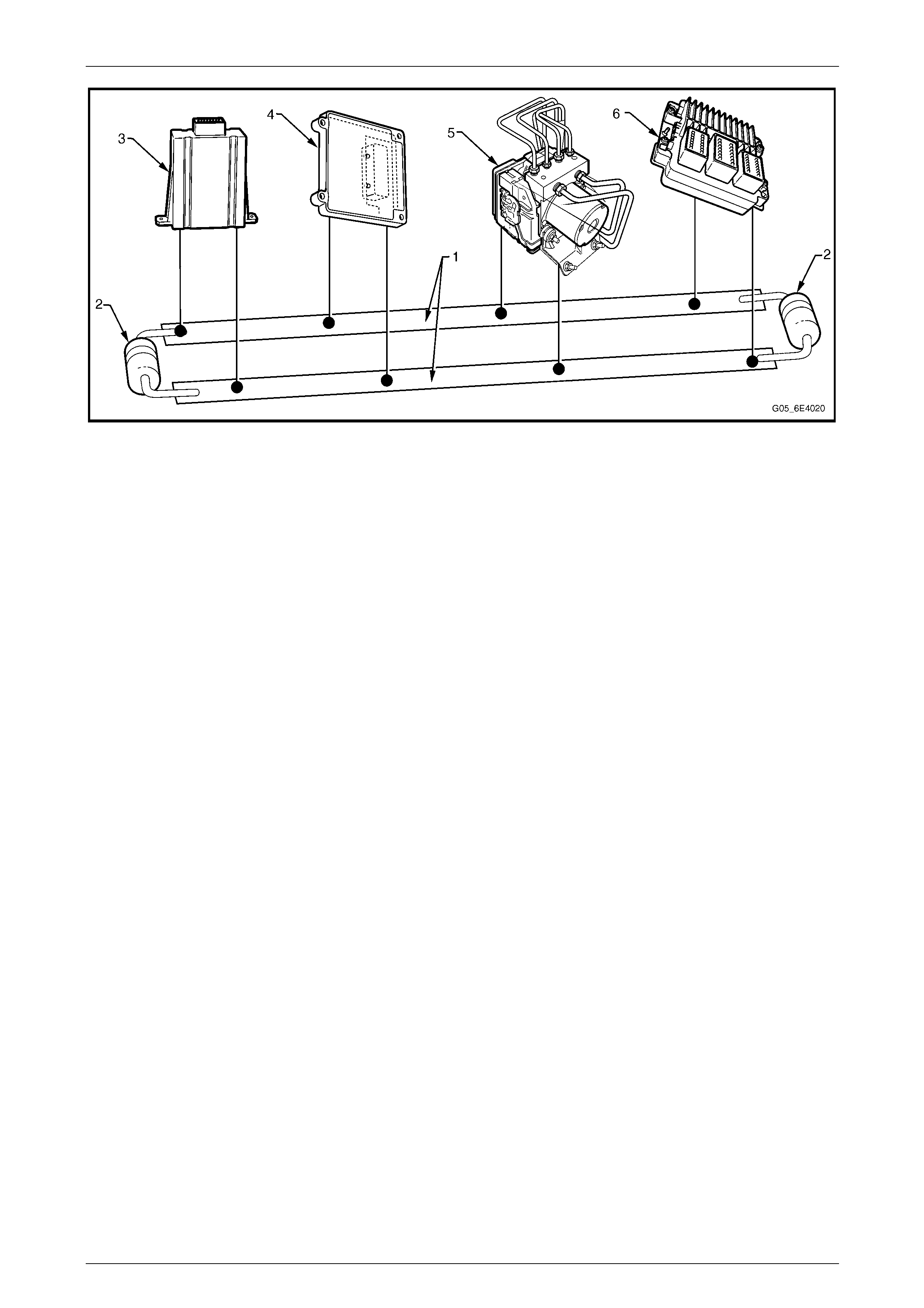
GM LAN Serial Data Bus
The GM LAN bus is a two wire circuit (1), refer to Figure 6E4 – 1. The GM LAN bus circuits are terminated with cut-off
resistors (2) which are locate d inside the two control modules at either end of the bus circuit. The purpos e of these cut-off
resistors is to prevent data from returning as an echo after reaching the end of the GM LAN bus circu it.
NOTE
For illustration purposes, the cut-off resistors are
shown outside of the control modules.
The two control modules with the cut-off resistors
are the PIM and the ECM.
Powertrain Interface Module – HSV – Gen IV V8 Page 6E4–7
Page 6E4–7
Figure 6E4 – 1
Legend
1 CAN Bus Lines
2 Cut-off Resistors (resistors are integrated into the PIM and
ECM)
3 Powertrain Interface Module (PIM)
4 Transmission Control Module (TCM)
5 ABS-TCS Electronic Control Unit (ECU)
6 Engine Control Module (ECM)
Serial Data
When information is sent from one control module to another via the serial data bus, the information sent is known as
serial data. Serial data in its electronic form, is made up of rapi dly changing high to low voltage pulses strung together.
Each string of voltage pulses represents a message.
• GM LAN serial data has two data lines along which serial data is sent. These lines are known as CAN HI and CAN
LO.
• CAN HI – The CAN HI data line is a 3.6 V data line that toggles the voltage between 2.5 V and 3.6 V
(referenced to ground). When there is no communication on the CAN HI data line, the system voltage
is 2.5 V.
• CAN LO – The CAN LO data line is a 2.5 V data line that toggles the voltage between 2.5 V and 1.4 V
(referenced to ground). When there is no communication on the CAN LO data line, the system voltage
is 2.5 V.
• UART serial data is a single 5 V data line that toggles the voltage to ground. When there is no communication on
the data line, the system voltage is 5 V.
Serial Data Communication Protocols
General Motors Local Area Network (GM LAN)
GM LAN is a communication protocol based on the Controller Area Network ph ysical layer. The main difference between
GM LAN and CAN is the way in which the messages are structured. It is a broadcast communications channel, not
master / slave like UART.
Universal Asynchronous Receive and Transmit (UART)
UART is a communication pro t ocol that has a master module which controls the message traffic on the serial data bus.
The body control module (BCM) is the UART bus master in the MY 200 4 HSV VZ. The main difference between
GM LAN and UART protocol is that UART relies on the bus master to control the messaging, where as with GM LAN, the
messaging is managed b y each of the control modules.
Powertrain Interface Module – HSV – Gen IV V8 Page 6E4–8
Page 6E4–8
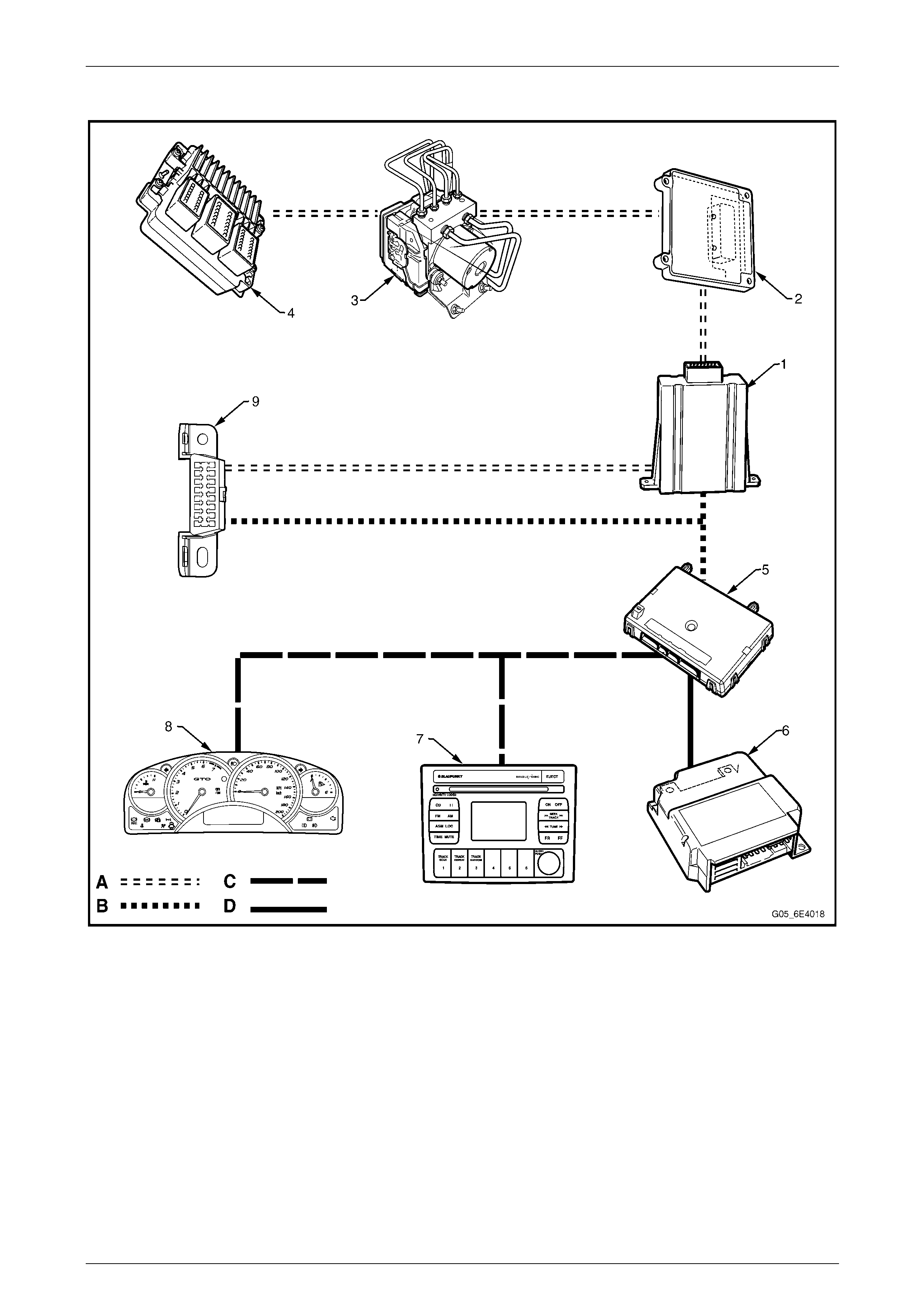
Serial Data Layout
Figure 6E4 – 2
Legend
1 Powertrain Interface Module (PIM)
2 Transmission Control Module (TCM)
3 ABS-TCS Electronic Control Unit (ECU)
4 Engine Control Module (ECM)
5 Body Control Module (BCM)
6 Occupant Protection System Sensing and Diagnostic
Module (SDM)
7 Audio Head Unit (AHU)
8 Instrument Cluster
9 Data Link Connector
A GM LAN Serial Data Circuit
B Primary UART Serial Data Circuit
C Secondary UART Serial Data Circuit
D Tertiary UART Serial Data Circuit
Powertrain Interface Module – HSV – Gen IV V8 Page 6E4–9
Page 6E4–9
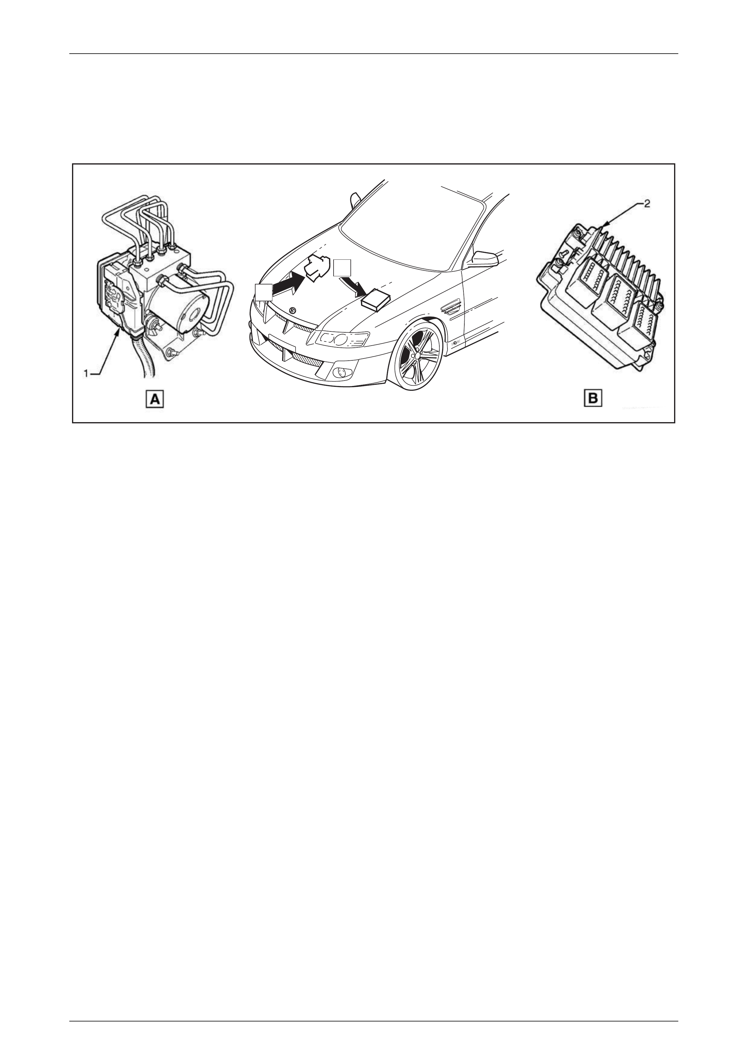
2 Component Location
2.1 Engine Compartment
B
A
Figure 6E4 – 3
Legend
1 ABS-TCS Electronic Control Unit (ECU) 2 Engine Control Module (ECM)
Powertrain Interface Module – HSV – Gen IV V8 Page 6E4–10
Page 6E4–10
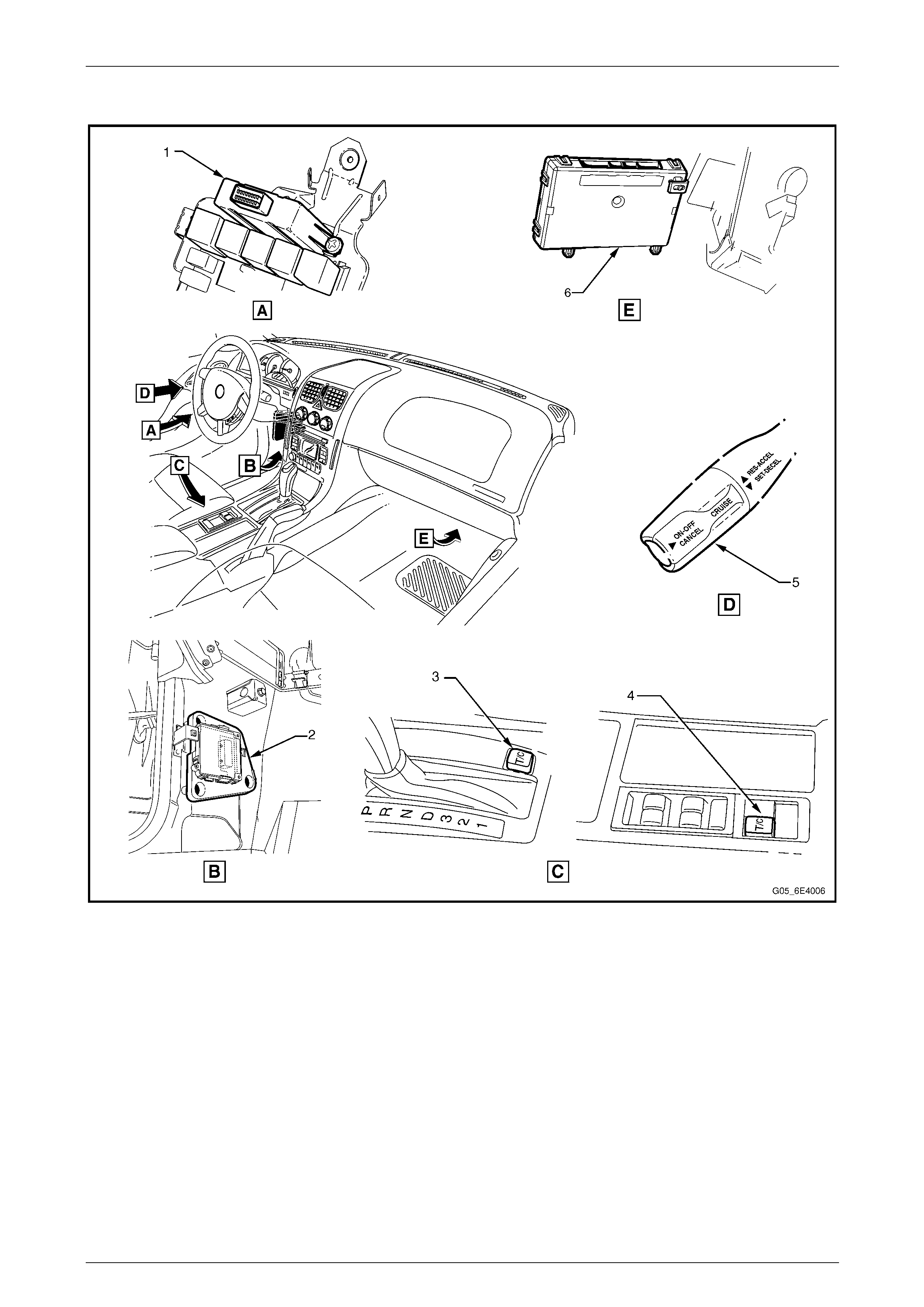
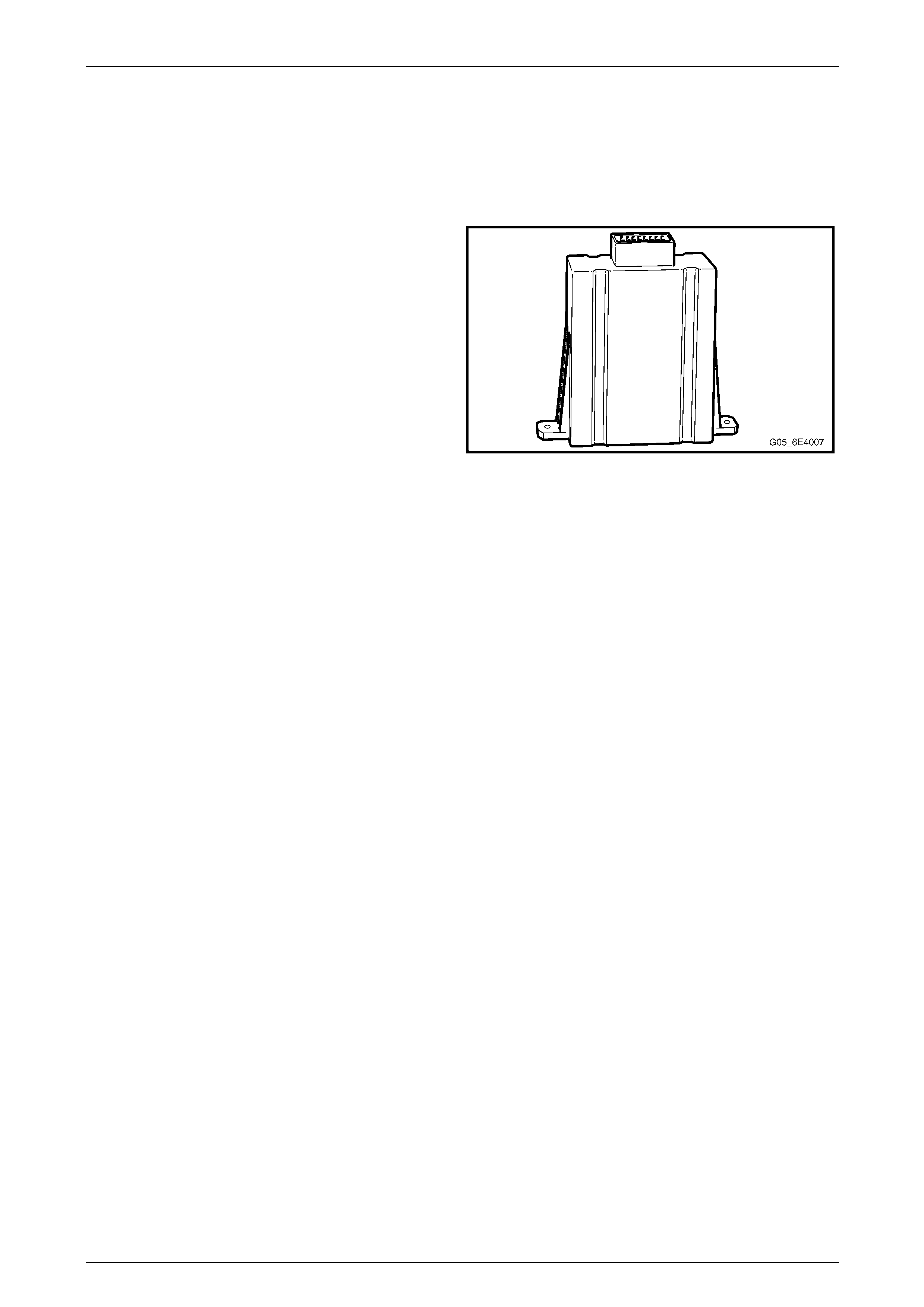
2.2 Interior
Figure 6E4 – 4
1 Powertrain Interface Module (PIM)
2 Transmission Control Module (TCM)
3 Traction Control Switch – Automatic Transmission
4 Traction Control Switch – Manual Transmission
5 Cruise Control Switch Assembly
6 Body Control Module (BCM)
Powertrain Interface Module – HSV – Gen IV V8 Page 6E4–11
Page 6E4–11
3 Component Description and
Operation
3.1 Pow ertrain Interface Module
The powertrain interface module (PIM) is located on the
driver's instrument panel outer bracket and is accessible by
lowering the instrument panel lower trim panel assembly.
Figure 6E4 – 5
Communication Gateway
The PIM performs the following functions:
• The PIM Acts as the communication gate way between the GM LAN communications protocol and the Universal
Asynchronous Receive and Transmit (UART) protocol.
As the GM LAN protocol is not compatible with UART, the PIM is integrated into the serial data commu nication
system to enable bi-directional communication flow between control modules on the UART side and the GM LAN
side of the communication net work.
• The PIM converts analogue si gnals from the cruise control and traction control s witches in to digital serial data.
• The PIM is responsible for au thenticating the body control module (BCM) prior to the engine control modul e (ECM)
authenticating the PIM. If any of these authentication processes fail, the vehicl e will not start. For further information
on the theft deterrent system, refer to Section 12J Body Control Module.
Powertrain Interface Module – HSV – Gen IV V8 Page 6E4–12
Page 6E4–12
3.2 Pow ertrain Interface Module Gateway
Components
The following components use the PIM to communicate between the UART and GM LAN communication protoco l:
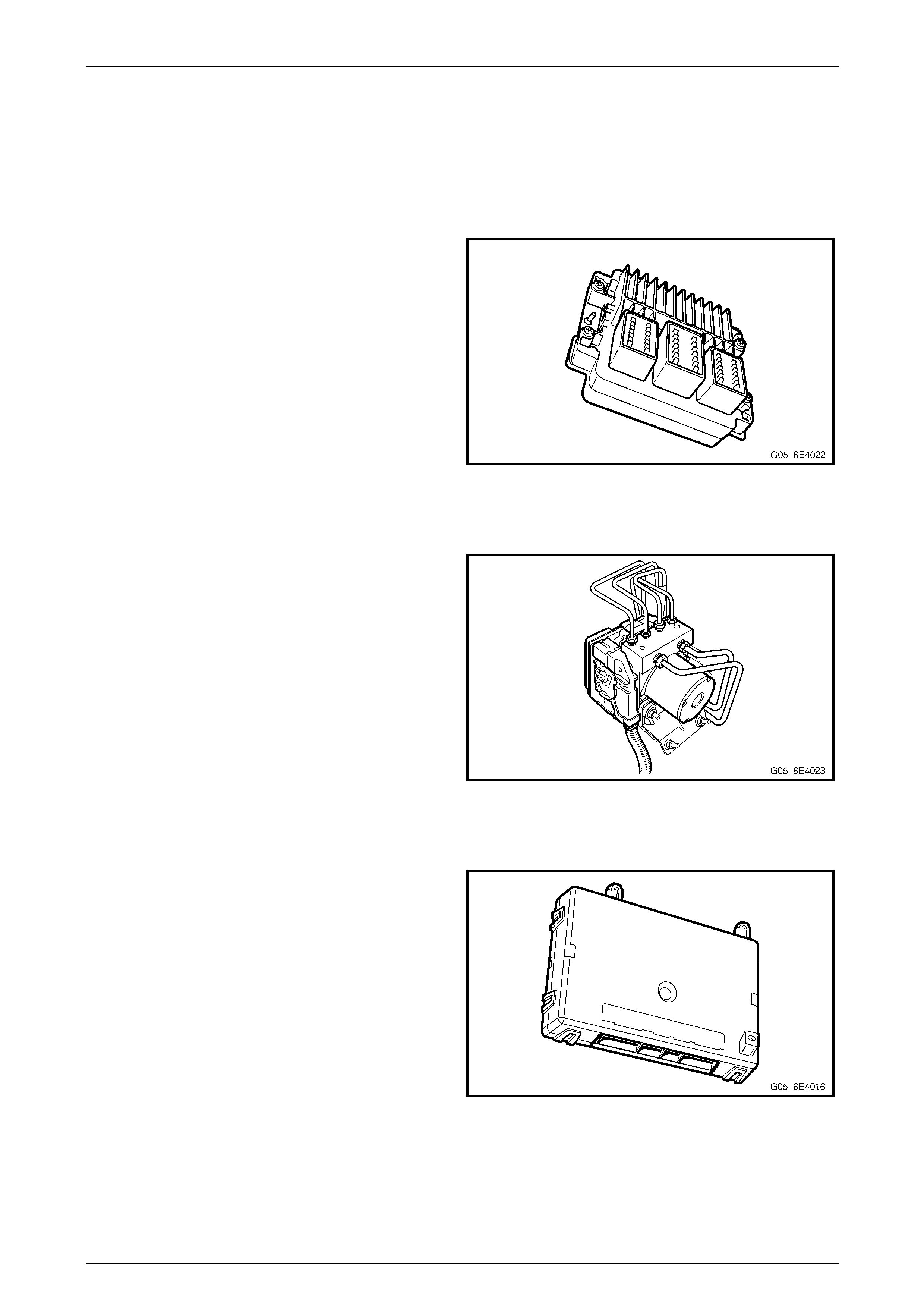
Engine Control Module
The ECM is located in the engine com partment on the
left-hand front wheelhouse panel.
The ECM communicates directly with the transmission
control module (TCM), ABS-TCS ECU and PIM via the
serial data network. The ECM, via the PIM, also
communicates with the BCM and instrument cluster.
The ECM is also an integral part of the vehicle security
system. For further information on vehicle security, refer to
Section 12J Body Control Module.
Figure 6E4 – 6
ABS-TCS Electronic Control Unit
The ABS-TCS ECU is located in the engine compartment
adjacent to the right-hand front wheelho use liner.
The primary role of the ABS-TCS is to efficiently control the
vehicle's braking and traction control operation. To
effectively do this, the ECU of the ABS-TCS communicates
with other vehicle systems such as the engin e mana gement
and automatic transmission systems.
This information exchange is achieved by connecting the
various system control modules via the serial data network.
For further information on the serial data network, refer to
1 General Information.
Figure 6E4 – 7
Body Control Module
The body control module (BCM) is mounted horizontally
behind the instrument panel compartment.
The BCM controls various vehicle electrica l systems, and is
an integral part of the serial data communication network.
The BCM communicates with other vehicle modules using
the Universal Asynchronous R eceive and Transmit (UART)
serial data protocol.
The BCM is connected to the PIM and the data link
connector (DLC) via the primary serial data circuit. The BCM
communicates via this circuit with the ECM, TCM and the
ABS-TCS ECU.
Refer to Section 12J Body Control Module for further
information on:
• serial data communication, a nd
• theft deterrent system.
Figure 6E4 – 8

Powertrain Interface Module – HSV – Gen IV V8 Page 6E4–13
Page 6E4–13
Automatic Transmission Control Module
The transmission control module (T CM) is located behind
the left-hand lower hinge pillar trim.
The TCM's primary role is to efficientl y control transmission
shift points according to current driving and vehicle
operating conditions. To effectively do this, the TCM
requires information from other vehicl e systems such as the
engine management and automatic transmission systems.
This information exchanged is achieved by connecting the
various system control modules via the serial data network.
For further information on the serial data network, refer to
1 General Information.
Figure 6E4 – 9
Powertrain Interface Module – HSV – Gen IV V8 Page 6E4–14
Page 6E4–14
3.3 Pow ertrain Interface Module Direct Input
Switches
The following switches are dir ect wired to the PIM. These switches use the PIM to convert their input signa ls into serial
data, which is then used by the various vehicle control modules to perform varying functions.
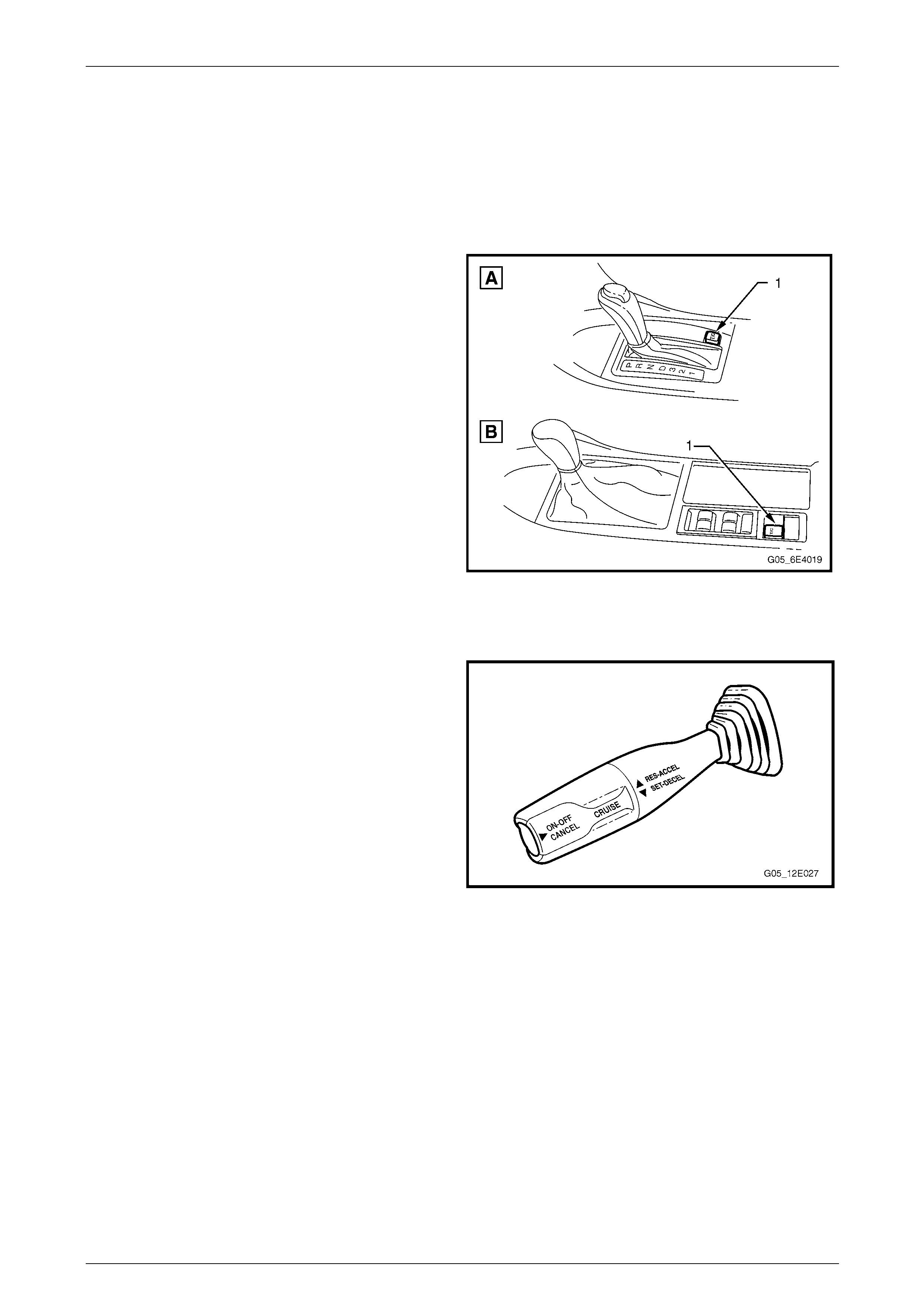
Traction Control System Switch
The traction control system (TCS) switch (1) for vehicles
with automatic transmission (View A) and manual
transmission (View B) is located at the rear of the floor
console.
The TCS switch is a momentary contact switch that enables
or disables the traction control system. The TCS switch
inputs directly into the PIM. When the TCS switch is
pressed, the PIM sends a message on the serial data bus to
the ABS-TCS ECU. Refer to Section 5B ABS-TCS for
further information on the ABS-TCS.
Figure 6E4 – 10
Cruise Control Switch
The Cruise Control S witch is located on the left-hand si de of
the steering column.
The switch is comprised of three momentary contact
switches which control the follo wing function s:
• cruise control push button switch (ON–OFF),
• cruise control resume – accelerate (RES–ACCEL),
and
• cruise control set – decelerate (SET–DECEL).
The three cruise control switches directly input into the PIM.
When any of these s witches are activated, the PIM sends a
message on the serial data bus to the ECM. For further
information on the cruise control system, refer to
Section 12E Cruise Control.
Figure 6E4 – 11

Powertrain Interface Module – HSV – Gen IV V8 Page 6E4–15
Page 6E4–15
4 Diagnostics
4.1 Diagnostic General Descriptions
The powertrain interface module (PIM) diagnostic procedure is organised in a logical stru cture that begins with the PIM
Main Diagnostic Table. The Main Diagnostic Table directs the diagnostic procedure to the logic al steps or appropriate
diagnostic table required to diagnose a PIM fault condition.
The diagnostic tables locate a faulty circuit or component through a logical based process of elimination. Correct use of
the diagnostic tables is essential to reduce di agnostic time and to prevent misdiagnosis.
In addition, the Main Diagnostic Table provides the following information:
• Identification of the PIM,
• condition of the diagnostic circuit, and
• identification and status of the DTCs if present.
Diagnostic Trouble Code (DTC) Tables
The diagnostic procedure is directed to a diagnostic trouble code (DTC) table if there are DTCs currently stored in the
PIM.
The diagnostic tables are designed to locate a faulty circuit or component through a logic al based process of elimination.
The diagnostic tables are developed with the following assumptions:
• the vehicle functioned correctly at the time of assembly,
• there are no multiple faults, and
• the problem currently exists.
Multiple DTCs
When performing a DTC check and there are multiple DT Cs, the diag nostic process must begin with the most likely DT C
that may trigger other DTCs. The following situation is an exampl e of a DT C that may trigger other vehicle system DTCs
to set.
• If there is an open circuit condition with the CAN HI circuit between the ABS-TCS ECU and the engine control
module (ECM), DTC U2105 Loss of Communications from ECM may set. This condition may also cause the
following DTCs to set in other control modules:
• Instrument cluster – DTC 11 No Serial Data from the ECM.
• ABS-TCS – DTC U2105 Lost Communication with the ECM.
• Transmission Control Module (TCM) – DTC U2105 Lost Communication with the ECM.
• Body Control Module (BCM) – DTC 7 No Serial Data from the ECM.
Knowledge of the PIM and Tech 2 limitations are important to reduce diagnostic time and to prevent misdiagnosis. Refer
to 5.1 Diagnostic Requirem ents, Precautions and Preliminary Tests.

Powertrain Interface Module – HSV – Gen IV V8 Page 6E4–16
Page 6E4–16
Diagnostic Trouble Codes (DTCs)
When the ignition s witch is turned on, the PIM performs an internal integrity check that detects and isol ates any internal
faults. The PIM also monitors the cruise control and traction control switch circuit and the serial data bus for messages
from the control modules on the GM LAN bus and from the BCM on the UA RT bus. If a fault is detected by the PIM, it will
log a Diagnostic Trouble Code (DTC) that represents the fault detected. The DTCs stored in the PIM may be accessed
using Tech 2. Refer to Section 0C Tech 2 for further information on Tech 2.
Status of DTCs
The PIM designates the DT Cs logged into a Current or History DTC.
Current DTCs
If the fault condition that triggers the DTC is present during the last PIM self test, that DTC will be designated as a current
DTC.
History DTCs
If the fault condition that triggers the DTC is not present during the last PIM self test, that DTC will be designated as a
history DTC.
Conditions for Clearing DTCs
• If there is no DTC logged in the current PIM self test, the current DTC will be cleared.
• If there is no DTC logged after 100 consecutive drive cycles, the history DTC will be cleared.
• Use of Tech 2 to clear the DTC.
Tech 2 PIM Diagnostic Tests
NOTE
Refer to Section 0C Tech 2 a nd the Tech 2 Users
Manual for detailed information and instructions
regarding the use of Tech 2.
Tech 2 Limitations
Some DTCs trigger other DTCs to set, which causes Tech 2 to display multiple DTCs. In those situations, Tech 2 may
display more DT Cs than is neede d to rectify a fault.
When Tech 2 displays an o utp ut function, it displays only the command given by the PIM. If a connector is disconnected,
that fault will not register in the PIM output function. Tech 2 does not verify the command action.
The service technician must understand t he system being diagnosed as well as the correct use and limitations of Tech 2
to be able to perform diagnostic procedures efficiently and successfully.
Tech 2 Intermittent Fault Tests
The following are lists of Tech 2 diagnostic tests that may be used to diagnose intermittent faults:
• Wiggle test the suspected PIM wiring harness and connector while obs erving Tech 2 operating parameters of the
circuit being tested. If Tech 2 read-out fluctuates during this procedure, check the wiring harness circuit for loose
connection.
• Road test the vehicle in conditions that trigger the intermittent fault while an assistant observes the suspected Tech
2 operating parameter data.
• Capture and store data in the Snapshot mode when the fault occurs. The stored data may be repl ayed at a slower
rate to aid in diagnostics. Refer to Tech 2 User Instructions for more infor mation o n the Snapshot function.
• Operate suspected components to test their operation using Tech 2 Output Control Data.

Powertrain Interface Module – HSV – Gen IV V8 Page 6E4–17
Page 6E4–17
Tech 2 Data List
The Tech 2 PIM Data List contains the operating parameters that may be used to analyse the PIM.
The technician is able to compare the op erating parameter of the vehicle being diagnosed to the typical data value of a
known serviceable vehicle.
NOTE
The Tech 2 Data List Typical Data Values are
obtained from a correctly operating vehicle under
the following conditions;
• ignition switched on,
• engine not running, and
• vehicle is stationary.
Tech 2 Data List Tabl e
Tech 2 Parameter Units Displayed Typical Data Value
Battery Voltage V 12.8
Immobiliser Activated Yes / No No
Cruise Control Enable Switch Inactive / Active Inactive
Cruise Control Enabled / Disabled Disabled
Cruise Control Tip Switch Inactive / Active Inactive
Traction Control Disable Switch Inactive / Active Inactive

Powertrain Interface Module – HSV – Gen IV V8 Page 6E4–18
Page 6E4–18
5 Powertrain Interface Module
Diagnostic Starting Point
5.1 Diagnostic Requirements, Precautions
and Preliminary Checks
Basic Knowledge Required
A lack of basic understanding of electronics,
electrical wiring circuits and use of electrical
circuit testing tools when performing the PIM
diagnostic procedures could result in
incorrect diagnostic results or damage to
components.
In addition, a general understanding of the PIM and its component operation is esse ntial to prevent misdiagnosis an d
component damage.
Basic Diagnostic Tools Required
Use of incorrect electrical circuit diagnostic
tools when performing the PIM diagnostic
procedures could result in incorrect
diagnostic results or damage to components.
The following electrical circuit testing tools are required to perform the diagnostic procedu r es detailed in this Section:
• Tech 2, refer to Section 0C Tech 2 for further information.
• Test light, refer to Section 12P Wiring Diagrams for further information.
• Digital multimeter with 10 MΩ ohms impedance, refer to Section 12P Wiring Diagrams for further information.
• Connector test adapter kit Tool No. J35616-A.

Powertrain Interface Module – HSV – Gen IV V8 Page 6E4–19
Page 6E4–19
Diagnostic Precautions
In addition to the safety and precautionary
measures listed in 9.1 Safety and
Precautionary Measures, the following
diagnostic precautions must be observed
when performing any PIM diagnostic
procedure:
• Use only the test equipment specified in the diagnostic tables. Other test equipment may either give incorrect
results or damage serviceable components.
• Do not clear any DTCs unless instructed.
• The fault must be present when using the DTC Diagnostic T ables. Otherwise, misdiagnosis or replacement of
serviceable parts may occur.
• Always use connector adapters such as those contained in connector test adapter kit Tool No. J35616-A to prevent
connector terminal damage.
• Thorough inspection of the wiring circuits and connectors listed in the diagnostic procedures must be performed,
otherwise misdiagnosis may occur.
• Inspect the electrical circuitry or connector terminals that are suspected to be causing the compl aint for the
following conditions:
• backed-out connector terminals,
• improper wiring connector mating,
• broken wiring connector locks,
• damaged connector terminals, and
• physical damage to the wiring harness.
• Before replacing a component, inspect its connector terminal for corrosion or deformation that may cause the fault
condition.
Preliminary Checks
The PIM preliminar y check examines easil y accessible components which may cause problems with the PIM. This visual
and physical inspection proc edure may quickly identify the fault condition and eliminate the need for additional diagnosis.
• Refer to Service Techlines for releva nt information regarding the fault condition.
• Ensure the battery is fully charged.
• Check the battery connections for corrosion or a loose terminal.
• Perform a visual and physical inspection of the following:
• PIM component wiring harness and terminals for proper connections, pinches or cuts, and
• PIM wiring harness routing which may b e positioned very close to a high v oltage or high current devices such
as aftermarket audio systems.
NOTE
High voltage or high current devices may induce
electrical noise on a circuit, which can interfere
with normal circuit operation.
• The PIM is sensitive to Electro-magnetic Interference (EMI). Check for incor rect aftermarket theft deterrent
devices, lights or mobile phon e installations if an intermittent malfunction is suspected.

Powertrain Interface Module – HSV – Gen IV V8 Page 6E4–20
Page 6E4–20
5.2 Main Diagnostic Table
Step Action Yes No
1 Have you met the basic diagnostic requirements listed in the PIM
Diagnostic Starting Point?
Go to Step 2
Refer to 5.1
Diagnostic
Requirements,
Precautions and
Preliminary Ch ecks
2 Have you read the Diagnostic Precautions?
Go to Step 3
Refer to 5.1
Diagnostic
Requirements,
Precautions and
Preliminary Ch ecks
3 Have you performed the Preliminary Checks ?
Go to Step 4
Refer to 5.1
Diagnostic
Requirements,
Precautions and
Preliminary Ch ecks
4 1 Switch off the ignition.
2 Connect Tech 2 to the Diagnostic Link Connector (DLC).
3 Switch on the ignition with the engine not running.
4 Press Tech 2 power button on.
Does Tech 2 screen illuminate and display Tech 2? Go to Step 5 Refer to Section 0C
Tech 2
5 Using Tech 2, perform a Module/ECU Presence Check.
Does Tech 2 display the BCM as being Present? Go to Step 7 Go to Step 6
6 Refer to Section 12J Body Control Module to rectify the BCM
communication fault.
Was the BCM communication fault rectified? Go to Step 7 –
7 Does Tech 2 display the PIM as being Present?
Go to Step 8
Refer to 5.3
Powertrain Interface
Module – Module
Presence Check
Failure Diagnostic
Table
8 Using Tech 2, view and record all DTCs.
Does Tech 2 display a ny DTCs? Go to Step 9
Refer to
6 Intermittent Fault
Conditions
9 Does DTC B1000, B1009, B1013, or B1014 fail this ignition cycle? Refer to 7.1 DTC
B1000, B1009,
B1013 or B1014 –
PIM Internal Fault
Diagnostic Table Go to Step 10
10 Does DTC U2100 fail this ignition cycle? Refer to 7.3 DTC
U2100 – No
Communication
With CAN Bus (High
Speed) Diagnostic
Table Go to Step 11
11 Does DTC U2106 fail this ignition cycle? Refer to 7.5 DTC
U2106 – CAN Bus
No Communication
with Transmission
Control Module Go to Step 12

Powertrain Interface Module – HSV – Gen IV V8 Page 6E4–21
Page 6E4–21
Step Action Yes No
12 Does DTC U2108 fail this ignition cycle? Refer to 7.6 DTC
U2108 – CAN Bus
No Communication
with ABS-TCS
Diagnostic Table Go to Step 13
13 Does DTC U2105 fail this ignition cycle? Refer to 7.4 DTC
U2105 – CAN Bus
No Communication
with Engine Control
Module Diagnostic
Table Go to Step 14
14 Does Tech 2 display multiple DTCs?
Go to Step 15
Refer to the DTC
Table of the DTC
displayed
15 Refer to the DTC Table of the fault condition that is most likely to
trigger multiple DTCs. Refer to 3.1 Diagnostic General Descriptions for
information on multiple DTCs fault condition. – –
When all diagno sis an d repairs are completed, clear all DTCs and check the system fo r correct operation.

Powertrain Interface Module – HSV – Gen IV V8 Page 6E4–22
Page 6E4–22
5.3 Powertrain Interface Module – Module
Presence Check Failure Diagnostic Table
Step Action Yes No
1 Was the PIM Main Diagnostic Table performed? Go to Step 2 Refer to 5.2 Main
Diagnostic Table
2 Test the following PIM circuits for a high resistance, open circuit or
short to ground fault condition. Refer to Section 12P W iring Diagrams
for information on electrical diagnosis:
• 12 V battery supply circuit 740 ,
• 12 V ignition circuit 300, and
• ground circuit 151
Has any fault been found and rectified? Go to Step 5 Go to Step 3
3 Test the UART serial data primary circuit 800 for a high resistance or
an open circuit fault condition
Has any fault been found and rectified? Go to Step 5 Go to Step 4
4 Replace the PIM. Refer to 9.2 Powertrain Interface Module.
Has the repair been completed? Go to Step 5 –
5 Using Tech 2, perform a Module/ECU Presence Check.
Does Tech 2 display the PIM as being Present? Go to Step 6 Refer to 5.2 Main
Diagnostic Table
6 1 Using Tech 2, clear all DTCs.
2 Switch off the ignition for 30 seconds.
3 Check for DTCs.
Are there any PIM DTCs displaye d? Refer to 5.2 Main
Diagnostic Table Go to Step 7
7 Are there other DTCs displayed? Refer to the
appropriate Section System OK
When all diagno sis an d repairs are completed, clear all DTCs and check the system fo r correct operation.

Powertrain Interface Module – HSV – Gen IV V8 Page 6E4–23
Page 6E4–23
6 Intermittent Fault Conditions
6.1 Intermittent Conditions Diagnostic Table
Description
A fault condition is intermittent if one of the following conditions exists:
• The fault condition is not al ways present.
• The fault condition cannot be presently duplicated.
• There is no Current DTC but a Histor y DTC is stored.
Diagnostic Table
Checks Actions
Preliminary • Perform the Preliminary Checks, refer to 2.4 Preliminary Checks.
• Gather information from the customer regarding the conditions that trigger the
intermittent fault such as:
• At what engine or ambient temperature range do es the fault occur?
• Does the fault occur when operating aftermarket electrical equi pment inside
the vehicle?
• Does the fault occur on rough roads or in wet road conditions?
• If the intermittent fault is a start and then stall condition, check theft deterrent
system. Refer to Section 12J Body Control Modu le.
Harness/ Connector Install Tech 2 and perform the Tech 2 Intermittent Fault Tests. Refer to
4.1 Diagnostic General Descriptio ns for information on Tech 2 ECU diagnostic tests.
Warning Indicator The following conditions may cause an intermittent Malfunction Indicator L amp fault with
no DTC listed:
• Electromagnetic Interference (EMI) caused by a faulty relay, ECM controlled
solenoid, switch or other external source.
• Incorrect installation of aftermarket electrical equipment such as the following:
• mobile phones,
• theft deterrent alarms,
• lights, or
• radio equipment.
• Loose PIM ground connections.

Powertrain Interface Module – HSV – Gen IV V8 Page 6E4–24
Page 6E4–24
Checks Actions
Temperature Related The Tech 2 Freeze Frame/Fa ilure Records or Snapshot dat a may be used if applicable
to the fault condition. Refer to 4.1 Diagnostic General Descriptions for information on
Tech 2 ECU diagnostic tests.
• If the intermittent fault is heat related, review the Tech 2 data in relationshi p to the
following:
• high ambient temperature,
• underhood / engine generate d heat,
• circuit generated heat due to a poor electrical connection or high electrical
load, and
• higher than normal load conditions (towing, etc.).
• If the intermittent fault is related to cold ambient or engine temperature, review the
Tech 2 data in relationship to the following:
• low ambient temperature, and
• the fault condition that occurs only on a cold start situation.
Additional Tests • Check for incorrect installation of aftermarket electrical equipment such as the
following:
• mobile phones,
• theft deterrent alarms,
• lights, or
• radio equipment.
• Check for electromagnetic Interference (EMI) caused by a faulty relay, ECM
controlled solenoid or switch. The fault is triggered when the relay or solenoi d is
activated.
• Check the A/C compressor clutch and some rela ys that contain a clamping diode
or resistor for an open circuit.
• Check the generator for a faulty rectifier bridge that may allow A/C noise into the
PIM electrical circuit.
When all diagnosis and rep airs are completed, check the engine management system for correct operation.

Powertrain Interface Module – HSV – Gen IV V8 Page 6E4–25
Page 6E4–25
7 DTC Tables
7.1 DTC B1000, B1009, B1013 or B1014 –
PIM Internal Fault
Circuit Description
The powertrain interface module (PIM) is the control centre for the communication language conversion between GM
LAN serial data and UART serial data. If there is an internal microprocessor integrity fault condition with the PIM, DTCs
B1000 and/or B1009, B1013 and B1014 sets.
Additional Information
• The following are descriptions of the DTCs:
• DTC B1000 – RAM Test Error
• DTC B1009 – EEPROM Checksum Error
• DTC B1013 – ROM Checksum Error
• DTC B1014 – Program ROM Checksum Error
• Refer to 8 Electrical Circuit and Connector Views, for the following information:
• PIM connector illustration and terminal assignment, and
• PIM wiring diagram.
• For intermittent fault conditions, refer to 6 Intermittent Fault Conditions.
• Always test the connectors related to this diagnostic procedure for shorted terminals or poor wiring connection
before replacing any component. Refer to Section 12P Wiring Diagrams fo r information on electrical fault diagnosis.
Conditions for Running the DTC B1000, B1009, B1013 or B1014
Conditions for running the DTC are:
• The ignition is switched on.
• The ignition volt age is 10.0 – 16.0 V.
Conditions for Setting the DTCs
An internal PIM fault exists.
Action Taken When the DTCs Set
The action taken when any of these DTCs set will depend on the severity of the error. This may vary from no visual or
audible warning messages to a Service Ve hicle Soon message displ ayed on the instrument cluster multi-functio n display.
Conditions for Clearing DTCs
Refer to 4.1 Diagnostic General Descriptions for information on the conditions for clearing DTCs.
Test Description
The following numbers refer to the step numbers in the diagnostic table:
2 This step checks if the DTC is current, and if so, indicates the PIM has an internal proble m.
3 This step checks the PIM ground and 12 V battery supply.
4 This step tests the PIM harness connector for servicea bility.

Powertrain Interface Module – HSV – Gen IV V8 Page 6E4–26
Page 6E4–26
DTC B1000, B1009, B1013 or B1014 Diagnostic Table
Step Action Yes No
1 Has the Main Diagnostic Table been performed? Go to Step 2 Refer to 5.2 Main
Diagnostic Table
2 1 Switch off the ignition for 30 seconds.
2 Operate the vehicle within the conditions for setting DTC B1000,
B1009, B1013 or B1014.
3 Using Tech 2, select the DTC displ ay function.
Does DTC B1000, B1009, B1013 or B1014 fail this ignition cycle? Go to Step 3
Refer to DTC
B1000, B1009,
B1013 or B1014
Diagnostic Aids
3 1 Test all ground circuits of the PIM for a high resistance or an
open circuit fault condition. Refer to Section 12P Wiring
Diagrams for information on electrical fault diagnosis.
2 Test the PIM fuses and replace as requ ired. Refer to
Section 12O Fuses, Relays and Wiring Harnesses.
3 Test the PIM battery supply voltage circuit for a high resistance,
open circuit or short to ground fault condition. Refer to
Section 12P Wiring Diagrams for information on el ectrical fault
diagnosis.
Has any fault been found and rectified? Go to Step 6 Go to Step 4
4 Inspect for poor connections at the PIM wiring connector. Refer to
Section 12P Wiring Diagrams for information on el ectrical fault
diagnosis.
Has any fault been found and rectified? Go to Step 6 Go to Step 5
5 Replace the PIM. Refer to 9.2 Powertrain Interface Module.
Has the repair been completed? Go to Step 6 –
6 1 Using Tech 2, clear the DTCs.
2 Switch off the ignition for 30 seconds.
3 Start the engine.
4 Operate the vehicle within the conditions for running the DTC.
Does DTC B1000, B1009, B1013 or B1 014 fail this ignition c ycle? Go to Step 2 Go to Step 7
7 Using Tech 2, select the DTC displa y function.
Does Tech 2 display a ny DTCs?
Go to the
appropriate DTC
Table System OK
When all diagno sis an d repairs are completed, clear all DTCs and check the system fo r correct operation.

Powertrain Interface Module – HSV – Gen IV V8 Page 6E4–27
Page 6E4–27
7.2 DTC U1304 – Lost Communications with
UART System
Circuit Description
The transmission control module (T CM), ABS-TCS electronic control module (ECU) and engine control module (ECM)
transmit and receive data using the GM LAN serial data protocol, while the body control module (BCM) and other ve hicle
control modules use the Universal Asynchronous Receive and Transmit (UART) serial data protocol.
As the GM LAN and UART protocols are not compatibl e, a powertrain interface module (PIM) is integrated into the serial
data system to enable communication b etween the two different protocols.
The PIM monitors the UART serial data bus for traffic, and if the PIM does not detect any traffic on the UART serial data
bus, DTC U1304 sets.
Additional Information
For additional information refer to:
• 8 Electrical Circuit and Connector Views, for the following information:
• PIM connector illustration and terminal assignment, and
• PIM wiring diagram.
• Section 12J Body Control Module for BCM diagnosis.
• 6 Intermittent Fault Conditions.
• Always test the connectors related to this diagnostic procedure for shorted terminals or poor wiring connection
before replacing any component. Refer to Section 12P Wiring Diagrams fo r information on electrical fault diagnosis.
Conditions for Running the DTC
Conditions for running the DTC are:
• The ignition is switched on.
• The ignition volt age is 10.0 – 16.0 V.
Conditions for Setting the DTC
The PIM does not see any serial data communication on the UART serial data circuit 800 for greater than 10 seconds.
Action Taken When the DTC Sets
DTC U1304 sets when there is a communic ation failure on the UART serial data bus. Tech 2 accesses DTC informatio n
via the UART serial data bus. If DTC U1304 is current, T ech 2 will be unabl e to display any PIM DTC information. If Tech
2 displays DTC U130 4, this DTC will only be displayed as a history DTC.
NOTE
DTC U1304 may set as a current DTC if there is
a fault with the PIM.
Conditions for Clearing the DTC
Refer to 4.1 Diagnostic General Descriptions for information on the conditions for clearing DTCs.
Test Description
The following numbers refer to the step numbers in the diagnostic table:
3 This step checks if Tech 2 can communicate with the BCM.
6 This step tests the PIM harness connector for servicea bility.

Powertrain Interface Module – HSV – Gen IV V8 Page 6E4–28
Page 6E4–28
DTC U1304 Diagnostic Table
Step Action Yes No
1 Has the Main Diagnostic Table been performed? Go to Step 2 Refer to 5.2 Main
Diagnostic Table
2 1 Switch off the ignition for 10 seconds.
2 Operate the vehicle within the conditions for setting DTC U1304.
3 Using Tech 2, select the DTC displ ay function.
Does DTC U1304 fail this ignition cycle? Go to Step 3 Refer to DTC U1304
Diagnostic Aids
3 Using Tech 2, view the BCM identification information.
Does Tech 2 display the BCM identification information? Go to Step 4
Refer to Section 12J
Body Control
Module
4 Using Tech 2, view the BCM Normal Mode Data.
Does Tech 2 display n ormal mode data? Go to Step 5
Refer to Section 12J
Body Control
Module
5 Inspect for poor connections at the PIM wiring connector. Refer to
Section 12P Wiring Diagrams for information on el ectrical fault
diagnosis.
Has any fault been found and rectified? Go to Step 7 Go to Step 6
6 Replace the PIM. Refer to 9.2 Powertrain Interface Module.
Has the repair been completed? Go to Step 7 –
7 1 Using Tech 2, clear the DTCs.
2 Switch off the ignition for 30 seconds.
3 Start the engine.
4 Operate the vehicle within the conditions for running the DTC.
Does DTC U1304 fail this ignition cycle? Go to Step 2 Go to Step 8
8 Using Tech 2, select the DTC displa y function.
Does Tech 2 display a ny DTCs?
Go to the
appropriate DTC
Table System OK
When all diagno sis an d repairs are completed, clear all DTCs and check the system fo r correct operation.

Powertrain Interface Module – HSV – Gen IV V8 Page 6E4–29
Page 6E4–29
7.3 DTC U2100 – No Communication With
CAN Bus (High Speed)
Circuit Description
The transmission control module (T CM), ABS-TCS electronic control unit (ECU) and engine control module (ECM)
transmit and receive data using the GM LAN serial data protocol, while the body control module (BCM) and other vehicle
control modules use the Universal Asynchronous Receive and Transmit (UART) serial data protocol.
As the GM LAN and UART protocols are not compatibl e, a powertrain interface module (PIM) is integrated into the serial
data system to enable communication b etween the two different protocols.
The PIM will detect if a short to ground or a short to voltage conditio n occurs on the GM LAN circuits 2501 (CAN LO line)
and 2500 (CAN HI line). If either of these conditions occur, DTC U2100 sets.
Additional Information
• Refer to 8 Electrical Circuit and Connector Views, for the following information:
• PIM connector illustration and terminal assignment, and
• PIM wiring diagram.
• For intermittent fault conditions, refer to 6 Intermittent Fault Conditions.
• Always test the connectors related to this diagnostic procedure for shorted terminals or poor wiring connection
before replacing any component. Refer to Section 12P Wiring Diagrams fo r information on electrical fault diagnosis.
Conditions for Running the DTC
Conditions for running the DTC are:
• The ignition is switched on.
• The ignition volt age is 10.0 – 16.0 V.
Conditions for Setting the DTC
The PIM detects a short to ground or short to voltage on the GM LAN circuits 2501 or 250 0 when the ignition is switched
on and the short condition exists for greater than five seconds.
NOTE
This DTC will only set when the ignition has
initially been turned to the On position, and will
not set when the vehicle is being driven.
Action Taken When the DTC Sets
NOTE
Depending on the severity of the fault, the
number of messages displayed ma y vary.
• When the DTC sets, the following messages may be displayed on the instrument cluster multi-function display:
• Service Vehicle Soon,
• Fuel Gauge Error – Contact Retailer, and
• TCS Fail.
• The instrument cluster will also display an ABS Off warning indicator.
Conditions for Clearing the DTC
Refer to 4.1 Diagnostic General Descriptions for information on the conditions for clearing DTCs.

Powertrain Interface Module – HSV – Gen IV V8 Page 6E4–30
Page 6E4–30
Test Description
The following numbers refer to the step numbers in the diagnostic table:
3 This step establishes if there is a fault with the ECM.
5 This step isolates whether the fault is between the ECM and the ABS-TCS ECU or with the ABS-TCS ECU.
6 This step tests GM LAN serial data circuits 2500 and 25 01 between the ABS-TCS ECU and the ECM.
8 This step isolates whether the fault is between the ABS-TCS ECU and the TCM or with the TCM.
9 This step tests GM LAN serial data circuits 2500 and 2501 between the ABS-TCS ECU and the TCM.
11 This step tests GM LAN serial data circuits 2500 and 2501 between the TCM and the PIM.
12 This step tests GM LAN serial data circuits 2500 and 2501 b etween the PIM and the data link connector.
13 This step tests PIM harness connector for serviceability.
DTC U2100 Diagnostic Table
Step Action Yes No
1 Has the Main Diagnostic Table been performed? Go to Step 2 Refer to 5.2 Main
Diagnostic Table
2 1 Switch off the ignition for 10 seconds.
2 Operate the vehicle within the conditions for setting DTC U2100.
3 Using Tech 2, select the DTC displ ay function.
Does DTC U2100 fail this ignition cycle? Go to Step 3 Refer to DTC U2100
Diagnostic Aids
3 1 Disconnect connector A43 – X1 from the ECM.
2 Switch off the ignition for 10 seconds.
3 Operate the vehicle within the conditions for setting DTC U2100.
4 Using Tech 2, select the DTC displ ay function.
NOTE
Other DTCs may set when the ECM connector is
disconnected and the ignition is switched on. Disregard
those DTCs that set under this condition on this DTC
Table.
Does DTC U2100 fail this ignition cycle? Go to Step 6 Go to Step 4
4 Inspect for poor connections at the ECM wiring connector. Refer to
Section 12P Wiring Diagrams for information on el ectrical fault
diagnosis.
Has any fault been found and rectified? Go to Step 18 Go to Step 5
5 Replace the ECM.
Has the repair been completed? Go to Step 18 –
6 1 Disconnect connector A37 – X1 from the ABS-TCS ECU.
2 Switch off the ignition for 10 seconds.
3 Operate the vehicle within the conditions for setting DTC U2100.
4 Using Tech 2, select the DTC displ ay function.
Does DTC U2100 fail this ignition cycle? Go to Step 10 Go to Step 7
7 Test the serial data circuits 2500 and 2501 between the ABS-TCS
ECU and the ECM for a short to voltage, short to ground or short
together condition. Refer to Section 12P Wiring Diagrams for
information on wiring circuit testing and repair.
Has any fault been found and rectified? Go to Step 18 Go to Step 8

Powertrain Interface Module – HSV – Gen IV V8 Page 6E4–31
Page 6E4–31
Step Action Yes No
8 Inspect for poor connections at the ABS-T CS ECU wiring connector.
Refer to Section 12P Wiring Diagrams for informatio n on el ectrical
fault diagnosis.
Has any fault been found and rectified? Go to Step 18 Go to Step 9
9 Replace the ABS-TCS ECU. Refer to Section 5B ABS-TCS.
Has the repair been completed? Go to Step 18 –
10 1 Disconnect connector A112 – X1 from the T CM.
2 Switch off the ignition for 10 seconds.
3 Operate the vehicle within the conditions for setting DTC U2100.
4 Using Tech 2, select the DTC displ ay function.
Does DTC U2100 fail this ignition cycle? Go to Step 14 Go to Step 11
11 Test the serial data circuits 2500 and 2501 between the TCM and the
ABS-TCS ECU for a short to voltage, short to ground or short together
condition. Refer to Section 12P Wiring Diagrams for information on
wiring circuit testing and repair.
Has any fault been found and rectified? Go to Step 18 Go to Step 12
12 Inspect for poor connections at the TCM wiring connector. Refer to
Section 12P Wiring Diagrams for information on el ectrical fault
diagnosis.
Has any fault been found and rectified? Go to Step 18 Go to Step 13
13 Replace the TCM. Refer to Section 7D4 Aut omatic Transmission -
4L65E – On-vehicle Servicing.
Has the repair been completed? Go to Step 18 –
14 Test the serial data circuits 2500 an d 2501 between the PIM and the
TCM for a short to voltage, short to ground or short together condition.
Refer to Section 12P Wiring Diagrams for information on wiring circuit
testing and repair.
Has any fault been found and rectified? Go to Step 18 Go to Step 15
15 Test the serial data circuits 2500 an d 2501 between the PIM and the
data link connector for a short to voltage, short to ground or short
together condition. Refer to Section 12P Wiring Diagrams for
information on wiring circuit testing and repair.
Has any fault been found and rectified? Go to Step 18 Go to Step 16
16 Inspect for shorted terminals or poor wiring connections at the PIM
wiring connector. Refer to Section 12P Wiring Diagrams for
information on electrical fault diagnosis.
Has any fault been found and rectified? Go to Step 18 Go to Step 17
17 Replace the PIM. Refer to 9.2 Powertrain Interface Module.
Has the repair been completed? Go to Step 18 –
18 1 Using Tech 2, clear the DTCs.
2 Switch off the ignition for 30 seconds.
3 Start the engine.
4 Operate the vehicle within the conditions for running the DTC.
Does DTC U2100 fail this ignition cycle? Go to Step 2 Go to Step 19
19 Using Tech 2, select the DTC displa y function.
Does Tech 2 display a ny DTCs?
Go to the
appropriate DTC
Table System OK
When all diagno sis an d repairs are completed, clear all DTCs and check the system fo r correct operation.

Powertrain Interface Module – HSV – Gen IV V8 Page 6E4–32
Page 6E4–32
7.4 DTC U2105 – CAN Bus No
Communication with Engine Control
Module
Circuit Description
The transmission control module (T CM), ABS-TCS electronic control unit (ECU) and engine control module (ECM)
transmit and receive data using the GM LAN serial data protocol, while the body control module (BCM) and other vehicle
control modules use the Universal Asynchronous Receive and Transmit (UART) serial data protocol.
As the GM LAN and UART protocols are not compatibl e, a powertrain interface module (PIM) is integrated into the serial
data system to enable communication b etween the two different protocols.
The PIM continuousl y receiv es messages from the ECM. If the PIM does not receive a message within a predetermine d
time, DTC U2105 sets.
Additional Information
• Refer to 8 Electrical Circuit and Connector Views, for the following information:
• PIM connector illustration and terminal assignment, and
• PIM wiring diagram.
• Refer to Section 6C4 Engine Management Gen IV for diagnostic information.
• For intermittent fault conditions, refer to 6 Intermittent Fault Conditions.
• Always test the connectors related to this diagnostic procedure for shorted terminals or poor wiring connection
before replacing any component. Refer to Section 12P Wiring Diagrams fo r information on electrical fault diagnosis.
Conditions for Running the DTC
Conditions for running the DTC are:
• The ignition is switched on.
• The ignition volt age is 10.0 – 16.0 V.
Conditions for Setting the DTC
The PIM does not receive a message from the ECM for 100 milliseconds.
Action Taken When the DTC U2105
• When the DTC sets, the following messages may be displayed on the instrument cluster multi-function display:
• Service Vehicle Soon,
• ABS Fail Message, and
• The instrument cluster will also display an ABS Off warning indicator.
Conditions for Clearing the DTC
Refer to 4.1 Diagnostic General Descriptions for information on the conditions for clearing DTCs.
Test Description
The following numbers refer to the step numbers in the diagnostic table:
4 This step tests GM LAN serial data circuits 2500 and 25 01 between the ECM and the ABS-TCS ECU.
5 This step tests the integrit y of the ECM 12 V ignition circuit and ground connections.
6 This step tests the ECM harness connector for serviceability.
8 This step tests the PIM harness connector for servicea bility.

Powertrain Interface Module – HSV – Gen IV V8 Page 6E4–33
Page 6E4–33
DTC U2105 Diagnostic Table
Step Action Yes No
1 Has the Main Diagnostic Table been performed? Go to Step 2 Refer to 5.2 Main
Diagnostic Table
2 1 Switch off the ignition for 10 seconds.
2 Operate the vehicle within the conditions for setting DTC U2105.
3 Using Tech 2, select the DTC displ ay function.
Does DTC U2105 fail this ignition cycle? Go to Step 3 Refer to DTC U2105
Diagnostic Aids
3 Using Tech 2, attempt to communicate with the ECM.
Does Tech 2 communicate with the ECM? Go to Step 8 Go to Step 4
4 Test the serial data circuits 2500 and 2501 between the ECM and the
ABS-TCS ECU for a high resistance or open circuit fault condition.
Refer to Section 12P Wiring Diagrams for information on wiring circuit
testing and repair.
Has any fault been found and rectified? Go to Step 10 Go to Step 5
5 Test the following ECM circuits for a high resistance, op en circuit or
short to ground fault condition. Refer to Section 12P W iring Diagrams
for information on electrical diagnosis:
• 12 V battery supply circuit 740 ,
• 12 V ignition circuit 139, and
• all ECM ground connections.
Has any fault been found and rectified? Go to Step 10 Go to Step 6
6 Inspect for poor connections at the ECM wiring connector. Refer to
Section 12P Wiring Diagrams for information on el ectrical fault
diagnosis.
Has any fault been found and rectified? Go to Step 10 Go to Step 7
7 Replace the ECM. Refer to Section 6C4 Engine Mana gement Gen IV.
Has the repair been completed? Go to Step 10 –
8 Inspect for poor connections at the PIM wiring connector. Refer to
Section 12P Wiring Diagrams for information on el ectrical fault
diagnosis.
Has any fault been found and rectified? Go to Step 10 Go to Step 9
9 Replace the PIM. Refer to 9.2 Powertrain Interface Module.
Has the repair been completed? Go to Step 10 –
10 1 Using Tech 2, clear the DTCs.
2 Switch off the ignition for 30 seconds.
3 Start the engine.
4 Operate the vehicle within the conditions for running the DTC.
Does DTC U2105 fail this ignition cycle? Go to Step 2 Go to Step 11
11 Using Tech 2, select the DTC displa y function.
Does Tech 2 display a ny DTCs?
Go to the
appropriate DTC
Table System OK
When all diagno sis an d repairs are completed, clear all DTCs and check the system fo r correct operation.

Powertrain Interface Module – HSV – Gen IV V8 Page 6E4–34
Page 6E4–34
7.5 DTC U2106 – CAN Bus No
Communication with Transmission
Control Module
Circuit Description
The transmission control module (T CM), ABS-TCS electronic control unit (ECU) and engine control module (ECM)
transmit and receive data using the GM LAN serial data protocol, while the body control module (BCM) and other vehicle
control modules use the Universal Asynchronous Receive and Transmit (UART) serial data protocol.
As the GM LAN and UART protocols are not compatibl e, a powertrain interface module (PIM) is integrated into the serial
data system to enable communication b etween the two different protocols.
The PIM continuousl y receiv es messages from the TCM. If the PIM does not receive a message within a predetermined
time, DTC U2106 sets.
Additional Information
• Refer to 8 Electrical Circuit and Connector Views, for the following information:
• PIM connector illustration and terminal assignment, and
• PIM wiring diagram.
• For intermittent fault conditions, refer to 6 Intermittent Fault Conditions.
• Always test the connectors related to this diagnostic procedure for shorted terminals or poor wiring connection
before replacing any component. Refer to Section 12P Wiring Diagrams for information on electrical fault diagnosis.
Conditions for Running the DTC
Conditions for running the DTC are:
• The ignition is switched on.
• The ignition volt age is 10.0 – 16.0 V.
Conditions for Setting the DTC
The PIM does not receive a message from the TCM for 1000 milliseconds, during the current ignition c ycle.
Action Taken When the DTC Sets
• When the DTC sets, the following messages may be displayed on the instrument cluster multi-function display:
• Service Vehicle Soon, and
• TCS Fail.
• The instrument cluster will also display an ABS Off warning indicator.
Conditions for Clearing the DTC
Refer to 4.1 Diagnostic General Descriptions for information on the conditions for clearing DTCs.
Test Description
The following numbers refer to the step numbers in the diagnostic table:
4 This step tests the TCM power and ground circuits.
5 This step tests GM LAN serial data circuits 2500 an d 2501 between the PIM and the TCM.
6 This step tests the internal GM LAN CAN HI circuit in the PIM.
7 This step tests the internal GM LAN CAN LO circuit in the PIM.
8 This step tests the TCM harness connector for serviceability.
9 This step tests the PIM harness connector for servicea bility.

Powertrain Interface Module – HSV – Gen IV V8 Page 6E4–35
Page 6E4–35
DTC U2106 Diagnostic Table
Step Action Yes No
1 Has the Main Diagnostic Table been performed? Go to Step 2 Refer to 5.2 Main
Diagnostic Table
2 1 Switch off the ignition for 10 seconds.
2 Operate the vehicle within the conditions for setting DTC U2106.
3 Using Tech 2, select the DTC displ ay function.
Does DTC U2106 fail this ignition cycle? Go to Step 3 Refer to DTC U2106
Diagnostic Aids
3 Using Tech 2, attempt to communicate with the TCM.
Does Tech 2 communicate with the TCM? Go to Step 10 Go to Step 4
4 Test the following TCM circuits for a high res istance, open circuit or
short to ground fault condition. Refer to Section 12P W iring Diagrams
for information on electrical diagnosis:
• 12 V battery supply voltage circuit 740,
• EFI Relay 12 V supply circ uits 339 and 1139, and
• all TCM ground connections
Has any fault been found and rectified? Go to Step 12 Go to Step 5
5 Test the serial data circuits 2500 an d 2501 between the PIM and the
TCM for a high resistance or open circuit fault conditi on. Refer to
Section 12P Wiring Diagrams for information on wiring circuit testing
and repair.
Has any fault been found and rectified? Go to Step 12 Go to Step 6
6 1 Disconnect connector A156 – X1 from the PIM.
2 Using a digital multimeter, measure the resistance between PIM
terminals, 18 and 17.
Does the digital multimeter displa y infinity? Go to Step 11 Go to Step 7
7 Using a digital multimeter, measure the resistance between the PIM
terminals 19 and 20.
Does the digital multimeter displa y infinity? Go to Step 11 Go to Step 8
8 Inspect for poor connections at the TCM wiring connector. Refer to
Section 12P Wiring Diagrams for information on el ectrical fault
diagnosis.
Has any fault been found and rectified? Go to Step 12 Go to Step 9
9 Replace the TCM. Refer to Section 7D4 Automatic Transmission.
Has the repair been completed? Go to Step 12 –
10 Inspect for poor connections at the PIM wiring connector. Refer to
Section 12P Wiring Diagrams for information on el ectrical fault
diagnosis.
Has any fault been found and rectified? Go to Step 12 Go to Step 11
11 Replace the PIM. Refer to 9.2 Powertrain Interface Module.
Has the repair been completed? Go to Step 12 –
12 1 Using Tech 2, clear the DTCs.
2 Switch off the ignition for 30 seconds.
3 Start the engine.
4 Operate the vehicle within the conditions for running the DTC.
Does DTC U2106 fail this ignition cycle? Go to Step 2 Go to Step 13
13 Using Tech 2, select the DTC displa y function.
Does Tech 2 display a ny DTCs? Go to the
appropriate DTC
Table System OK
When all diagno sis an d repairs are completed, clear all DTCs and check the system fo r correct operation.

Powertrain Interface Module – HSV – Gen IV V8 Page 6E4–36
Page 6E4–36
7.6 DTC U2108 – CAN Bus No
Communication with ABS-TCS
Electronic Control Unit
Circuit Description
The transmission control module (T CM), ABS-TCS electronic control unit (ECU) and engine control module (ECM)
transmit and receive data using the GM LAN serial data protocol, while the body control module (BCM) and other vehicle
control modules use the Universal Asynchronous Receive and Transmit (UART) serial data protocol.
As the GM LAN and UART protocols are not compatibl e, a powertrain interface module (PIM) is integrated into the serial
data system to enable communication b etween the two different protocols.
The PIM continuousl y receiv es messages from the ABS-TCS ECU. If the PIM does not receive a message within a
predetermined time, DTC U2108 sets.
Additional Information
• Refer to 8 Electrical Circuit and Connector Views, for the following information:
• PIM connector illustration and terminal assignment, and
• PIM wiring diagram.
• For intermittent fault conditions, refer to 6 Intermittent Fault Conditions.
• Always test the connectors related to this diagnostic procedure for shorted terminals or poor wiring connection
before replacing any component. Refer to Section 12P Wiring Diagrams fo r information on electrical fault diagnosis.
Conditions for Running the DTC
Conditions for running the DTC are:
• The ignition is switched on.
• The ignition volt age is 10.0 – 16.0 V.
Conditions for Setting the DTC
The PIM does not receive a message from the ABS-TCS ECU for 300 milliseconds, during the curr ent ignition cycle.
Action Taken When the DTC Sets
• When the DTC sets, the following messages may be displayed on the instrument cluster multi-function display:
• Service Vehicle Soon, and
• TCS Fail.
• The instrument cluster will also display an ABS Off warning indicator.
Conditions for Clearing the DTC
Refer to 4.1 Diagnostic General Descriptions for information on the conditions for clearing DTCs.
Test Description
The following numbers refer to the step numbers in the diagnostic table:
4 This step tests the ABS-TCS power and ground circuits.
6 For vehicles with manual transmission, this step tests GM LAN serial data circuits 2500 and 2501 between the PIM
and the ABS-TCS ECU.
7 This step tests the internal GM LAN CAN HI circuit in the PIM.
8 This step tests the internal GM LAN CAN LO circuit in the PIM.
9 For vehicles with automatic transmission, this step tests GM LAN serial d ata circuits 25 00 and 2501 between the
TCM and the ABS-TCS ECU.
10 This step tests the ABS-TCS ECU harness connector for se rviceability.
12 This step tests the PIM harness connector for serviceability.

Powertrain Interface Module – HSV – Gen IV V8 Page 6E4–37
Page 6E4–37
DTC U2108 Diagnostic Table
Step Action Yes No
1 Has the Main Diagnostic Table been performed? Go to Step 2 Refer to 5.2 Main
Diagnostic Table
2 1 Switch off the ignition for 10 seconds.
2 Operate the vehicle within the conditions for setting DTC U2108.
3 Using Tech 2, select the DTC displ ay function.
Does DTC U2108 fail this ignition cycle? Go to Step 3 Refer to DTC U2108
Diagnostic Aids
3 Using Tech 2, attempt to communicate with the ABS-TCS ECU.
Does Tech 2 communicate with the ABS-TCS ECU? Go to Step 12 Go to Step 4
4 Test the following ABS-TCS circuits for a high resistanc e, open circuit
or short to ground fault condition. Refer to Section 12P Wiring
Diagrams for information on electrical diagnosis:
• 12 V battery supply voltage circuits 542, 642 and 1440,
• 12 V ignition supply circuits 839 and 3 an d
• all ABS-TCS ground connections.
Has any fault been found and rectified? Go to Step 12 Go to Step 5
5 Is this vehicle fitted with manual transmission? Go to Step 6 Go to Step 9
6 Test the serial data circuits 2500 an d 2501 between the PIM and the
ABS-TCS ECU for a high resistance or open circuit fault condition.
Refer to Section 12P Wiring Diagrams for information on wiring circuit
testing and repair.
Has any fault been found and rectified? Go to Step 14 Go to Step 7
7 1 Disconnect connector A156 – X1 from the PIM.
2 Using a digital multimeter, measure the resistance between PIM
terminals 17 and 18.
Does the digital multimeter displa y infinity? Go to Step 13 Go to Step 8
8 Using a digital multimeter, measure the resistance between PIM
terminals, 19 and 20.
Does the digital multimeter displa y infinity? Go to Step 13 Go to Step 10
9 Test the serial data circuits 2500 and 2501 between the TCM and the
ABS-TCS ECU for a high resistance or open circuit fault condition.
Refer to Section 12P Wiring Diagrams for information on wiring circuit
testing and repair.
Has any fault been found and rectified? Go to Step 14 Go to Step 10

Powertrain Interface Module – HSV – Gen IV V8 Page 6E4–38
Page 6E4–38
Step Action Yes No
10 Inspect for poor connections at the ABS-T CS ECU wiring connector.
Refer to Section 12P Wiring Diagrams for informatio n on el ectrical
fault diagnosis.
Has any fault been found and rectified? Go to Step 14 Go to Step 11
11 Replace the ABS-TCS ECU. Refer to Section 5B ABS-TCS.
Has the repair been completed? Go to Step 14 –
12 Inspect for poor connections at the PIM wiring connector. Refer to
Section 12P Wiring Diagrams for information on el ectrical fault
diagnosis.
Has any fault been found and rectified? Go to Step 8 Go to Step 7
13 Replace the PIM. Refer to 9.2 Powertrain Interface Module.
Has the repair been completed? Go to Step 8 –
14 1 Using Tech 2, clear the DTCs.
2 Switch off the ignition for 30 seconds.
3 Start the engine.
4 Operate the vehicle within the conditions for running the DTC.
Does DTC U2108 fail this ignition cycle? Go to Step 2 Go to Step 15
15 Using Tech 2, select the DTC displa y function.
Does Tech 2 display a ny DTCs?
Go to the
appropriate DTC
Table System OK
When all diagno sis an d repairs are completed, clear all DTCs and check the system fo r correct operation.

Powertrain Interface Module – HSV – Gen IV V8 Page 6E4–39
Page 6E4–39
7.7 DTC P0565 – Cruise Control On Signal
Malfunction
Circuit Description
The cruise control on / off switch is a normally open switch that closes when the switch is activated. When activated, the
switch supplies signal voltage to the cruise control on signal circuit. The powertrain interface module (PIM) converts the
signal voltage input into serial data, which is used by the engine control module (ECM) to enable or disable the cruise
control system, and by the instrument cluster to display cruise control status.
Additional Information
• Refer to Section 12E Cruise Control for the following information:
• Cruise control switch description, operation and inspection procedures, and
• Cruise control wiring diagram.
• Refer to 8 Electrical Circuit and Connector Views, for the following information:
• PIM connector illustration and terminal assignment, and
• PIM wiring diagram.
• For intermittent fault conditions, refer to 6 Intermittent Fault Conditions.
• Always test the connectors related to this diagnostic procedure for shorted terminals or poor wiring connection
before replacing any component. Refer to Section 12P Wiring Diagrams fo r information on electrical fault diagnosis.
Conditions for Running the DTC
Conditions for running the DTC are:
• The ignition is switched on.
• The ignition volt age is 10.0 – 16.0 V.
Conditions for Setting the DTC
The PIM detects the cruise control on / off function of the cruise control switch assembly is the ON position for 60
seconds or more.
Action Taken When the DTC Sets
When the DTC sets, there is no message displa yed on the multi-function display.
If the cruise control is active at the time the DTC sets, the PIM will disable cruise co ntrol.
Conditions for Clearing the DTC
Refer to 4.1 Diagnostic General Descriptions for information on the conditions for clearing DTCs.
NOTE
If the fault is not evident for greater than 60
seconds, the DTC will become a histor y DTC and
cruise control can be resumed .
Test Description
The following numbers refer to the step numbers in the diagnostic table:
2 This step tests the cruise control on / off switch using Tech 2.
6 This step tests the cruise control on / off switch signal circuit.
7 This step tests the PIM harness connector for servicea bility.

Powertrain Interface Module – HSV – Gen IV V8 Page 6E4–40
Page 6E4–40
DTC P0565 Diagnostic Table
Step Action Yes No
1 Has the Main Diagnostic Table been performed? Go to Step 2 Refer to 5.2 Main
Diagnostic Table
2 Using Tech 2, view the cruise control on / off switch status parameter
in the PIM data list.
Does Tech 2 display Active? Go to Step 4 Go to Step 3
3 1 Switch off the ignition for 10 seconds.
2 Operate the vehicle within the conditions for setting DTC P0565.
3 Using Tech 2, select the DTC displ ay function.
Does DTC P0565 fail this ignition cycle? Go to Step 4 Refer to DTC P0565
Diagnostic Aids
4 1 Disconnect connector S43 – X1 from the cruise control switch
assembly.
2 Using Tech 2, view the cruise control on / off switch status
parameter in the PIM data list.
Does Tech 2 display Active? Go to Step 6 Go to Step 5
5 Replace the cruise control s witch, refer to Section 12E Cruise Control.
Has the repair been completed? Go to Step 9 –
6 Test the cruise control on / off switch signal circuit for a short to
voltage. Refer to Section 12P Wiring Diagrams for information on
electrical fault diagnos is.
Has any fault been found and rectified? Go to Step 9 Go to Step 7
7 Inspect for shorted terminals or poor connec tions at the PIM wiring
connector. Refer to Section 12P Wiring Diagrams for information on
electrical fault diagnos is.
Has any fault been found and rectified? Go to Step 9 Go to Step 8
8 Replace the PIM. Refer to 9.2 Powertrain Interface Module.
Has the repair been completed? Go to Step 9 –
9 1 Using Tech 2, clear the DTCs.
2 Switch off the ignition for 30 seconds.
3 Start the engine.
4 Operate the vehicle within the conditions for running the DTC.
Does DTC P0565 fail this ignition cycle? Go to Step 2 Go to Step 10
10 Using Tech 2, select the DTC displa y function.
Does Tech 2 display a ny DTCs?
Go to the
appropriate DTC
Table System OK
When all diagno sis an d repairs are completed, clear all DTCs and check the system fo r correct operation.

Powertrain Interface Module – HSV – Gen IV V8 Page 6E4–41
Page 6E4–41
7.8 DTC P0567 – Cruise Control Resume
Signal Malfunction
Circuit Description
The cruise control resume switch is a normally open s witch that closes when the switch is activated. When activated, the
switch supplies signal voltage to the cruise control resume signal circuit. T he po wertrain interface module (PIM) converts
the signal voltage input into serial data, which is used by the engine control module (ECM) to resume cruise control
operation.
Additional Information
• Refer to Section 12E Cruise Control for the following information:
• Cruise control switch description, operation and inspection procedures, and
• Cruise control wiring diagram.
• Refer to 8 Electrical Circuit and Connector Views, for the following information:
• PIM connector illustration and terminal assignment, and
• PIM wiring diagram.
• For intermittent fault conditions, refer to 6 Intermittent Fault Conditions.
• Always test the connectors related to this diagnostic procedure for shorted terminals or poor wiring connection
before replacing any component. Refer to Section 12P Wiring Diagrams fo r information on electrical fault diagnosis.
Conditions for Running the DTC
Conditions for running the DTC are:
• The ignition is switched on.
• The ignition volt age is 10.0 – 16.0 V.
Conditions for Setting the DTC
The PIM detects the cruise control resume function of the cruise control switch assembly is in the RESUME position for
60 seconds or more.
Action Taken When the DTC Sets
When the DTC sets, there is no message displa yed on the multi-function display.
If the cruise control is active at the time the DTC sets, the PIM will disable cruise co ntrol.
Conditions for Clearing the DTC
Refer to 4.1 Diagnostic General Descriptions for information on the conditions for clearing DTCs.
NOTE
If the fault is not evident for greater than 60
seconds, the DTC will become a histor y DTC and
cruise control can be resumed .
Test Description
The following numbers refer to the step numbers in the diagnostic table:
2 This step tests the cruise control resume switch using T ech 2.
6 This step tests the cruise control resume switch signal circuit.
7 This step tests the PIM harness connector for servicea bility.

Powertrain Interface Module – HSV – Gen IV V8 Page 6E4–42
Page 6E4–42
DTC P0567 Diagnostic Table
Step Action Yes No
1 Has the Main Diagnostic Table been performed? Go to Step 2 Refer to 5.2 Main
Diagnostic Table
2 Using Tech 2, view the cruise control resume switch status parameter
in the PIM data list.
Does Tech 2 display Active? Go to Step 4 Go to Step 3
3 1 Switch off the ignition for 10 seconds.
2 Operate the vehicle within the conditions for setting DTC P0567.
3 Using Tech 2, select the DTC displ ay function.
Does DTC P0567 fail this ignition cycle? Go to Step 4 Refer to DTC P0567
Diagnostic Aids
4 1 Disconnect connector S43 – X1 from the cruise control switch
assembly.
2 Using Tech 2, view the cruise control resume s witch status
parameter in the PIM data list.
Does Tech 2 display Active? Go to Step 6 Go to Step 5
5 Replace the cruise control switch assembl y, refer to
Section 12E Cruise Control.
Has the repair been completed? Go to Step 9 –
6 Test the cruise control resume switch signal circuit for a short to
voltage. Refer to Section 12P Wiring Diagrams for information on
electrical fault diagnos is.
Has any fault been found and rectified? Go to Step 9 Go to Step 7
7 Inspect for shorted terminals or poor connec tions at the PIM wiring
connector. Refer to Section 12P Wiring Diagrams for information on
electrical fault diagnos is.
Has any fault been found and rectified? Go to Step 9 Go to Step 8
8 Replace the PIM. Refer to 9.2 Powertrain Interface Module.
Has the repair been completed? Go to Step 9 –
9 1 Using Tech 2, clear the DTCs.
2 Switch off the ignition for 30 seconds.
3 Start the engine.
4 Operate the vehicle within the conditions for running the DTC.
Does DTC P0567 fail this ignition cycle? Go to Step 2 Go to Step 10
10 Using Tech 2, select the DTC displa y function.
Does Tech 2 display a ny DTCs?
Go to the
appropriate DTC
Table System OK
When all diagno sis an d repairs are completed, clear all DTCs and check the system fo r correct operation.

Powertrain Interface Module – HSV – Gen IV V8 Page 6E4–43
Page 6E4–43
7.9 DTC P0568 – Cruise Control Set Signal
Malfunction
Circuit Description
The cruise control set switch is a normally open switch that closes when the switch is activated. When ac tivated, the
switch supplies signal voltage to the cruise control set signal circuit. The powertrain interface module (PIM) converts the
signal voltage input into serial data, which is used by the engine control module (ECM) to set the vehicl e speed.
Additional Information
• Refer to Section 12E Cruise Control for the following information:
• Cruise control switch description, operation and inspection procedures, and
• Cruise control wiring diagram.
• Refer to 8 Electrical Circuit and Connector Views, for the following information:
• PIM connector illustration and terminal assignment, and
• PIM wiring diagram.
• For intermittent fault conditions, refer to 6 Intermittent Fault Conditions.
• Always test the connectors related to this diagnostic procedure for shorted terminals or poor wiring connection
before replacing any component. Refer to Section 12P Wiring Diagrams fo r information on electrical fault diagnosis.
Conditions for Running the DTC
Conditions for running the DTC are:
• The ignition is switched on.
• The ignition volt age is 10.0 – 16.0 V.
Conditions for Setting the DTC
The PIM detects the cruise control set function of the cruise control switch assembly is in the SET position for 60
seconds or more.
Action Taken When the DTC Sets
When the DTC sets, there is no message displa yed on the multi-function display.
If the cruise control is active at the time the DTC sets, the PIM will disable cruise co ntrol.
Conditions for Clearing the DTC
Refer to 4.1 Diagnostic General Descriptions for information on the conditions for clearing DTCs.
NOTE
If the fault is not evident for greater than 60
seconds, the DTC will become a histor y DTC and
cruise control can be resumed .
Test Description
The following numbers refer to the step numbers in the diagnostic table:
2 This step tests the cruise control set switch using Tech 2.
6 This step tests the cruise control set switch signal circuit.
7 This step tests the PIM harness connector for servicea bility.

Powertrain Interface Module – HSV – Gen IV V8 Page 6E4–44
Page 6E4–44
DTC P0568 Diagnostic Table
Step Action Yes No
1 Has the Main Diagnostic Table been performed? Go to Step 2 Refer to 5.2 Main
Diagnostic Table
2 Using Tech 2, view the cruise control set switch status parameter in
the PIM data list.
Does Tech 2 display Active? Go to Step 4 Go to Step 3
3 1 Switch off the ignition for 10 seconds.
2 Operate the vehicle within the conditions for setting DTC P0568.
3 Using Tech 2, select the DTC displ ay function.
Does DTC P0568 fail this ignition cycle? Go to Step 4 Refer to DTC P0568
Diagnostic Aids
4 1 Disconnect connector S43 – X1 from the cruise control switch
assembly.
2 Using Tech 2, view the cruise control set switch status
parameter in the PIM data list.
Does Tech 2 display Active? Go to Step 6 Go to Step 5
5 Replace the cruise control switch assembl y, refer to
Section 12E Cruise Control.
Has the repair been completed? Go to Step 9 –
6 Test the cruise control set switch signal circuit for a short to voltage.
Refer to Section 12P Wiring Diagrams for informatio n on el ectrical
fault diagnosis.
Has any fault been found and rectified? Go to Step 9 Go to Step 7
7 Inspect for shorted terminals or poor connec tions at the PIM wiring
connector. Refer to Section 12P Wiring Diagrams for information on
electrical fault diagnos is.
Has any fault been found and rectified? Go to Step 9 Go to Step 8
8 Replace the PIM. Refer to 9.2 Powertrain Interface Module.
Has the repair been completed? Go to Step 9 –
9 1 Using Tech 2, clear the DTCs.
2 Switch off the ignition for 30 seconds.
3 Start the engine.
4 Operate the vehicle within the conditions for running the DTC.
Does DTC P0568 fail this ignition cycle? Go to Step 2 Go to Step 10
10 Using Tech 2, select the DTC displa y function.
Does Tech 2 display a ny DTCs?
Go to the
appropriate DTC
Table System OK
When all diagno sis an d repairs are completed, clear all DTCs and check the system fo r correct operation.

Powertrain Interface Module – HSV – Gen IV V8 Page 6E4–45
Page 6E4–45
7.10 DTC P1611 – Wrong Security Code
Entered
Circuit Description
Tech 2 is used to program the powertrain interface modu le ( PIM). Before any programming, a security code must be
entered into Tech 2. The PIM will check if the code entered is correct before continuing. If the security code is incorrect,
DTC P1611 sets.
After an incorrect security code is entered, the PIM prevents any further attempts to enter a code until a predetermined
wait time elapses. There are 10 wait time stages, and for each stage, an incorrect security code may be entered three
times before the lockout time is escalated to the next stage. The lockout stages are as follo ws:
• Stage 1 wait time is 10 seconds.
• Stage 2 wait time is 10 seconds.
• Stage 3 wait time is 10 minutes.
• Stage 4 wait time is 20 minutes.
• Stage 5 wait time is 40 minutes.
• Stage 6 wait time is 80 minutes.
Additional Information
• Refer to 10.4 BCM Link to ECM for PIM Security Code.
• Refer to 8 Electrical Circuit and Connector Views, for the following information:
• PIM connector illustration and terminal assignment, and
• PIM wiring diagram.
• For intermittent fault conditions, refer to 6 Intermittent Fault Conditions.
• Always test the connectors related to this diagnostic procedure for shorted terminals or poor wiring connection
before replacing any component. Refer to Section 12P Wiring Diagrams fo r information on electrical fault diagnosis.
Conditions for Running the DTC
Conditions for running the DTC are:
• The ignition is switched on.
• The ignition volt age is 10.0 – 16.0 V.
Conditions for Setting the DTC
An incorrect security code is entered into Tech 2 when attempting to program the PIM.
Action Taken When the DTC Sets
When the DTC sets, the following action is taken:
• The vehicle will not start whilst the PIM is in a lock-out state.
NOTE
When the DTC sets, there is no message
displayed on the instrument cluster multi-function
display.
Conditions for Clearing the DTC
Refer to 4.1 Diagnostic General Descriptions for information on the conditions for clearing DTCs.

Powertrain Interface Module – HSV – Gen IV V8 Page 6E4–46
Page 6E4–46
Test Description
The following numbers refer to the step numbers in the diagnostic table:
4 This step tests the PIM ground circuits and supply voltage.
5 This step tests the PIM harness connector for servicea bility.
DTC P1611 Diagnostic Table
Step Action Yes No
1 Has the Main Diagnostic Table been performed? Go to Step 2 Refer to 5.2 Main
Diagnostic Table
2 1 Switch off the ignition for 30 seconds.
2 Using Tech 2, select the DTC displ ay function.
NOTE
Do not attempt to perform any Tech 2 function that
requires the PIM security code to be entered.
Does DTC P1611 fail this ignition cycle? Go to Step 5 Go to Step 3
3 Using Tech 2, attempt a programming function that requires the PIM
security code to be entered. Refer to 10 PIM Security and
Programming.
Was the programming function successfully performed? System OK Go to Step 4
4 1 Test all ground circuits of the PIM for a high resistance or an
open circuit fault condition. Refer to Section 12P Wiring
Diagrams for information on electrical fault diagnosis.
2 Test the PIM ignition supply voltage circuit for a high resistance,
open circuit or short to ground fault condition. Refer to
Section 12P Wiring Diagrams for information on el ectrical fault
diagnosis.
Has any fault been found and rectified? Go to Step 7 Go to Step 5
5 Inspect for poor connections at the PIM wiring connector. Refer to
Section 12P Wiring Diagrams for information on el ectrical fault
diagnosis.
Has any fault been found and rectified? Go to Step 7 Go to Step 6
6 Replace the PIM. Refer to 9.2 Powertrain Interface Module.
Has the repair been completed? Go to Step 7 –
7 1 Using Tech 2, clear the DTCs.
2 Switch off the ignition for 30 seconds.
Does DTC P1611 fail this ignition cycle? Go to Step 2 Go to Step 8
8 Using Tech 2, select the DTC displa y function.
Does Tech 2 display a ny DTCs?
Go to the
appropriate DTC
Table System OK
When all diagno sis an d repairs are completed, clear all DTCs and check the system fo r correct operation.

Powertrain Interface Module – HSV – Gen IV V8 Page 6E4–47
Page 6E4–47
7.11 DTC P1678 – Engine Control Module
Identification Failed
Circuit Description
After the ignition switch is turned to the ON position, and the powertrain interface module (PIM) has auth enticate d the
body control module (BCM), the PIM sends an encrypted security code to the engine control module (ECM). The ECM
compares the received security code with its own security code, and if it is valid, the ECM enables th e vehicle to be
started. If the security code received by the ECM is incorrect, DTC P1678 sets.
Additional Information
• Refer to 10.4 BCM Link to ECM for information on the ECM to PIM Linking.
• Refer to Section 12J Body Control Module for the following information:
• BCM link to PIM, and
• Theft Deterrent System.
• Refer to 8 Electrical Circuit and Connector Views, for the following information:
• PIM connector illustration and terminal assignment, and
• PIM wiring diagram.
• Refer to Section 6C4 Engine Management Gen IV V8 for diagnostic information.
• For intermittent fault conditions, refer to 6 Intermittent Fault Conditions.
• Always test the connectors related to this diagnostic procedure for shorted terminals or poor wiring connection
before replacing any component. Refer to Section 12P Wiring Diagrams fo r information on electrical fault diagnosis.
Conditions for Running the DTC
Conditions for running the DTC are:
• The ignition is switched on.
• The ignition volt age is 10.0 – 16.0 V.
Conditions for Setting the DTC
The ECM does not receive a valid response from the PIM when an attempt is made to start the engine.
Action Taken When the DTC Sets
When the DTC sets, the following action is taken:
• The vehicle will not start during the current ignition cycle.
• A Service Vehicle Soon message is d isplayed on the instrument cluster multi-function display.
Conditions for Clearing the DTC
Refer to 4.1 Diagnostic General Descriptions for information on the conditions for clearing DTCs.
Test Description
The following numbers refer to the step numbers in the diagnostic table:
4 This step checks if the PIM and ECM have been linked together.
5 This step ensures there are no problems within the ECM system that may cause DTC P1678 to set.
6 This step tests the PIM ground circuits and supply voltage.
7 This step tests the PIM harness connector for servicea bility.

Powertrain Interface Module – HSV – Gen IV V8 Page 6E4–48
Page 6E4–48
DTC P1678 Diagnostic Table
Step Action Yes No
1 Has the Main Diagnostic Table been performed? Go to Step 2 Refer to 5.2 Main
Diagnostic Table
2 1 Switch off the ignition for 30 seconds.
2 Operate the vehicle within the conditions for setting DTC P1678.
3 Using Tech 2, select the DTC displ ay function.
Does DTC P1678 fail this ignition cycle? Go to Step 3 Refer to DTC P1678
Diagnostic Aids
3 Does DTC B3924 set at the same time? Refer to DTC B3924
Diagnostic Table Go to Step 4
4 Using Tech 2, perform the PIM Link to ECM procedure. Refer to
10.4 BCM Link to ECM.
Has the linking procedure performed correctly? Go to Step 9 Go to Step 5
5 Check the ECM system. Refer to Section 6C4 Engine Management
Gen IV V8.
Has any fault been found and rectified? Go to Step 9 Go to step 6
6 1 Test all ground circuits of the PIM for a high resistance or an
open circuit fault condition. Refer to Section 12P Wiring
Diagrams for information on electrical fault diagnosis.
2 Test the PIM ignition supply voltage circuit for a high resistance,
open circuit or short to ground fault condition. Refer to Section
12P Wiring Diagrams for information on el ectrical fault
diagnosis.
Has any fault been found and rectified? Go to Step 9 Go to Step 7
7 Inspect for poor connections at the PIM wiring connector. Refer to
Section 12P Wiring Diagrams for information on el ectrical fault
diagnosis.
Has any fault been found and rectified? Go to Step 9 Go to Step 8
8 Replace the PIM. Refer to 9.2 Powertrain Interface Module.
Has the repair been completed? Go to Step 9 –
9 1 Using Tech 2, clear the DTCs.
2 Switch off the ignition for 30 seconds.
3 Start the engine.
4 Operate the vehicle within the conditions for running the DTC.
Does DTC P1678 fail this ignition cycle? Go to Step 2 Go to Step 10
10 Using Tech 2, select the DTC displa y function.
Does Tech 2 display a ny DTCs?
Go to the
appropriate DTC
Table System OK
When all diagno sis an d repairs are completed, clear all DTCs and check the system fo r correct operation.

Powertrain Interface Module – HSV – Gen IV V8 Page 6E4–49
Page 6E4–49
7.12 DTC B1019 – Transmission Control
Module Configuration Mismatch
Circuit Description
The powertrain interface module (PIM) is configured for either a manual or automatic transmission vehicle. If the PIM is
configured for manual transmission and it receives any messages on the GM LAN which originate from the transmission
control module (TCM), DTC B1019 sets.
Additional Information
• Refer to 10.3 PIM Configuration for the following information:
• Transmission configuration.
• Refer to 8 Electrical Circuit and Connector Views, for the following information:
• PIM connector illustration and terminal assignment, and
• PIM wiring diagram.
• For intermittent fault conditions, refer to 6 Intermittent Fault Conditions.
• Always test the connectors related to this diagnostic procedure for shorted terminals or poor wiring connection
before replacing any component. Refer to Section 12P Wiring Diagrams fo r information on electrical fault diagnosis.
Conditions for Running the DTC
Conditions for running the DTC are:
• The ignition is switched on.
• The ignition volt age is 10.0 – 16.0 V.
• The vehicle is fitted with an automatic transmission.
Conditions for Setting the DTC
Conditions for setting the DTC are:
• The PIM is configured for manual transmission and receives a message from the TCM via the GM LAN bus.
Action Taken When the DTC Sets
When the DTC sets, there is no message displa yed on the multi-function display.
Conditions for Clearing the DTC
Refer to 4.1 Diagnostic General Descriptions for information on the conditions for clearing DTCs.
Test Description
The following numbers refer to the step numbers in the diagnostic table:
2 This step determines if the PIM is configured for manual transmissio n.
5 This step tests the PIM ground circuits and supply voltage.
6 This step tests the PIM harness connector for servicea bility.

Powertrain Interface Module – HSV – Gen IV V8 Page 6E4–50
Page 6E4–50
DTC B1019 Diagnostic Table
Step Action Yes No
1 Has the Main Diagnostic Table been performed? Go to Step 2 Refer to 5.2 Main
Diagnostic Table
2 1 Switch off the ignition for 30 seconds.
2 Operate the vehicle within the conditions for setting DTC B1019.
3` Using Tech 2, select the DTC displa y function.
Does DTC B1019 fail this ignition cycle? Go to Step 3 Refer to DTC B1019
Diagnostic Aids
3 Using Tech 2, check if the PIM is configured for manual transmission?
Is the PIM configured for manual transmission? Go to Step 4 Go to Step 5
4 Using Tech 2, configure the PIM for automatic transmission. Refer to
10.3 PIM Configuration.
Is the PIM configured for automatic transmission ? Go to Step 8 Go to Step 5
5 1 Test all ground circuits of the PIM for a high resistance or an
open circuit fault condition. Refer to Section 12P Wiring
Diagrams for information on electrical fault diagnosis.
2 Test the PIM ignition supply voltage circuit for a high resistance,
open circuit or short to ground fault condition. Refer to Section
12P Wiring Diagrams for information on el ectrical fault
diagnosis.
Has any fault been found and rectified? Go to Step 8 Go to Step 6
6 Inspect for poor connections at the PIM wiring connector. Refer to
Section 12P Wiring Diagrams for information on el ectrical fault
diagnosis.
Has any fault been found and rectified? Go to Step 8 Go to Step 7
7 Replace the PIM. Refer to 9.2 Powertrain Interface Module.
Has the repair been completed? Go to Step 8 –
8 1 Using Tech 2, clear the DTCs.
2 Switch off the ignition for 30 seconds.
3 Start the engine.
4 Operate the vehicle within the conditions for running the DTC.
Does DTC B1019 fail this ignition cycle? Go to Step 2 Go to Step 9
9 Using Tech 2, select the DTC displa y function.
Does Tech 2 display a ny DTCs?
Go to the
appropriate DTC
Table System OK
When all diagno sis an d repairs are completed, clear all DTCs and check the system fo r correct operation.

Powertrain Interface Module – HSV – Gen IV V8 Page 6E4–51
Page 6E4–51
7.13 DTC B2745 – Traction Control Switch
Signal Malfunction
Circuit Description
The traction control switch is a normally open switch that closes when the switch is activated. When activated, the switch
supplies signal ground to the traction control ground signal circuit. The Powertrain Interface Module (PIM) converts the
signal ground input into serial data, which is used by the ABS-TCS electronic control unit (ECU) to enable or disa ble
traction control, and by the instrument cluster to display traction control status.
Additional Information
• Refer to Section 5B ABS-TCS for the following information:
• Traction control switch description, operation and inspection proce dure, and
• ABS-TCS wiring diagram.
• Refer to 8 Electrical Circuit and Connector Views, for the following information:
• PIM connector illustration and terminal assignment, and
• PIM wiring diagram.
• For intermittent fault conditions, refer to 6 Intermittent Fault Conditions.
• Always test the connectors related to this diagnostic procedure for shorted terminals or poor wiring connection
before replacing any component. Refer to Section 12P Wiring Diagrams fo r information on electrical fault diagnosis.
Conditions for Running the DTC
Conditions for running the DTC are:
• The ignition is switched on.
• The ignition volt age is 10.0 – 16.0 V.
Conditions for Setting the DTC
The PIM detects the traction control switch is activated for 60 seconds or more.
Action Taken When the DTC Sets
A TRAC OFF message is displayed on the instrument cluster multi-function displa y.
Conditions for Clearing the DTC
Refer to 4.1 Diagnostic General Descriptions for information on the conditions for clearing DTCs.
Test Description
The following numbers refer to the step numbers in the diagnostic table:
2 This step tests the traction control s witch using Tech 2.
6 This step tests the traction control switch signal circuit.
6 This step tests the PIM harness connector for servicea bility.

Powertrain Interface Module – HSV – Gen IV V8 Page 6E4–52
Page 6E4–52
DTC B2745 Diagnostic Table
Step Action Yes No
1 Has the Main Diagnostic Table been performed? Go to Step 2 Refer to 5.2 Main
Diagnostic Table
2 Using Tech 2, view the traction control switch status parameter in the
PIM data list.
Does Tech 2 display Active? Go to Step 4 Go to Step 3
3 1 Switch off the ignition for 10 seconds.
2 Operate the vehicle within the conditions for setting DTC B2745.
3 Using Tech 2, select the DTC displ ay function.
Does DTC B2745 fail this ignition cycle? Go to Step 4 Refer to DTC B2745
Diagnostic Aids
4 1 Disconnect connector S73 – X1 from the traction control switch.
2 Using Tech 2, view the traction control switch status parameter
in the PIM data list.
Does Tech 2 display Active? Go to Step 6 Go to Step 5
5 Replace the traction control switch, refer to Section 5B ABS-TCS.
Has the repair been completed? Go to Step 9 –
6 Test the traction control switch ground signa l circuit for a short to
ground. Refer to Section 12P Wiring Diagrams for information on
electrical fault diagnos is.
Has any fault been found and rectified? Go to Step 9 Go to Step 7
7 Inspect for shorted terminals or poor connec tions at the PIM wiring
connector. Refer to Section 12P Wiring Diagrams for information on
electrical fault diagnos is.
Has any fault been found and rectified? Go to Step 9 Go to Step 8
8 Replace the PIM. Refer to 9.2 Powertrain Interface Module.
Has the repair been completed? Go to Step 9 –
9 1 Using Tech 2, clear the DTCs.
2 Switch off the ignition for 30 seconds.
3 Start the engine.
4 Operate the vehicle within the conditions for running the DTC.
Does DTC B2745 fail this ignition cycle? Go to Step 2 Go to Step 10
10 Using Tech 2, select the DTC displa y function.
Does Tech 2 display a ny DTCs?
Go to the
appropriate DTC
Table System OK
When all diagno sis an d repairs are completed, clear all DTCs and check the system fo r correct operation.

Powertrain Interface Module – HSV – Gen IV V8 Page 6E4–53
Page 6E4–53
7.14 DTC B3924 – Wrong Environment
Identifier Received from Body Control
Module
Circuit Description
After as the ignition switch is turned to the ON position, the body control module (BCM) sends an encr y pted security
code to the powertrain interface module (PIM). The PIM compares the received security code with its own security code,
and if it is valid, the PIM via the engine control module (ECM) enab les the vehicle to be started. If the securit y code
received by the PIM is incorrect, DTC B3924 sets.
Additional Information
• Refer to Section 12J Body Control Module for the following information:
• BCM link to PIM, and
• Theft Deterrent System.
• Refer to 8 Electrical Circuit and Connector Views, for the following information:
• PIM connector illustration and terminal assignment, and
• PIM wiring diagram.
• For intermittent fault conditions, refer to 6 Intermittent Fault Conditions.
• Always test the connectors related to this diagnostic procedure for shorted terminals or poor wiring connection
before replacing any component. Refer to Section 12P Wiring Diagrams fo r information on electrical fault diagnosis.
Conditions for Running the DTC
Conditions for running the DTC are:
• The ignition is switched on.
• The ignition volt age is 10.0 – 16.0 V.
• The PIM does not receive a valid response from the BCM.
Conditions for Setting the DTC
Conditions for setting the DTC are:
• The ignition is switched on.
• The ignition volt age is 10.0 – 16.0 V.
Action Taken When the DTC Sets
When the DTC sets, the following action is taken:
• The vehicle will not start during the current ignition cycle, and
• A Immobiliser Failed message is displayed on the instrument cluster multi-function disp lay.
Conditions for Clearing the DTC
Refer to 4.1 Diagnostic General Descriptions for information on the conditions for clearing DTCs.
Test Description
The following numbers refer to the step numbers in the diagnostic table:
3 This Step checks if the PIM and ECM have been linked together.
4 This Step ensures there are n o problems within the BCM system that may cause DTC B3924 to set.
6 This step tests the PIM ground circuits and supply voltage.
7 This step tests the PIM harness connector for servicea bility.

Powertrain Interface Module – HSV – Gen IV V8 Page 6E4–54
Page 6E4–54
DTC B3924 Diagnostic Table
Step Action Yes No
1 Has the Main Diagnostic Table been performed? Go to Step 2 Refer to 5.2 Main
Diagnostic Table
2 1 Switch off the ignition for 30 seconds.
2 Operate the vehicle within the conditions for setting DTC B3924.
3 Using Tech 2, select the DTC displ ay function.
Does DTC B3924 fail this ignition cycle? Go to Step 3 Refer to DTC B3924
Diagnostic Aids
3 Using Tech 2, perform the BCM Link to PIM procedure. Refer to
Section 12J Body Control Module.
Was the linking procedure performed corr ectly? Go to Step 8 Go to Step 4
4 Test the BCM system. Refer to Section 12J Body Control Module.
Has any fault been found and rectified? Go to Step 8 Go to Step 5
5 1 Test all ground circuits of the PIM for a high resistance or an
open circuit fault condition. Refer to Section 12P Wiring
Diagrams for information on electrical fault diagnosis.
2 Test the PIM ignition supply voltage circuit for a high resistance,
open circuit or short to ground fault condition. Refer to
Section 12P Wiring Diagrams for information on el ectrical fault
diagnosis.
Has any fault been found and rectified? Go to Step 8 Go to Step 6
6 Inspect for poor connections at the PIM wiring connector. Refer to
Section 12P Wiring Diagrams for information on el ectrical fault
diagnosis.
Has any fault been found and rectified? Go to Step 8 Go to Step 7
7 Replace the PIM. Refer to 9.2 Powertrain Interface Module.
Has the repair been completed? Go to Step 8 –
8 1 Using Tech 2, clear the DTCs.
2 Switch off the ignition for 30 seconds.
3 Start the engine.
4 Operate the vehicle within the conditions for running the DTC.
Does DTC B3924 fail this ignition cycle? Go to Step 2 Go to Step 9
9 Using Tech 2, select the DTC displa y function.
Does Tech 2 display a ny DTCs?
Go to the
appropriate DTC
Table System OK
When all diagno sis an d repairs are completed, clear all DTCs and check the system fo r correct operation.
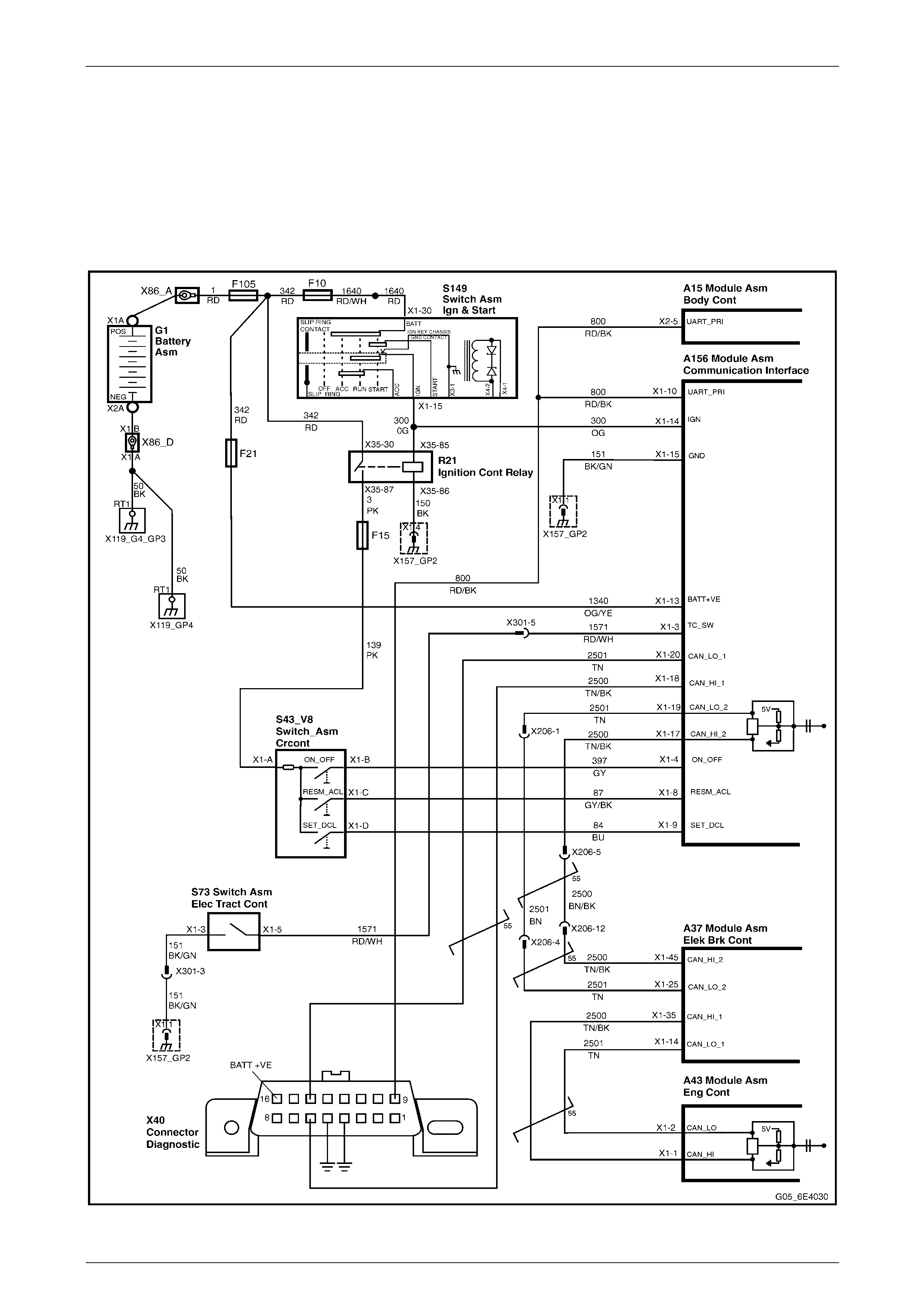
Powertrain Interface Module – HSV – Gen IV V8 Page 6E4–55
Page 6E4–55
8 Electrical Circuit and Connector
Vi e w s
8.1 PIM Electrical Circuit
With Manual Transmission
Figure 6E4 – 12
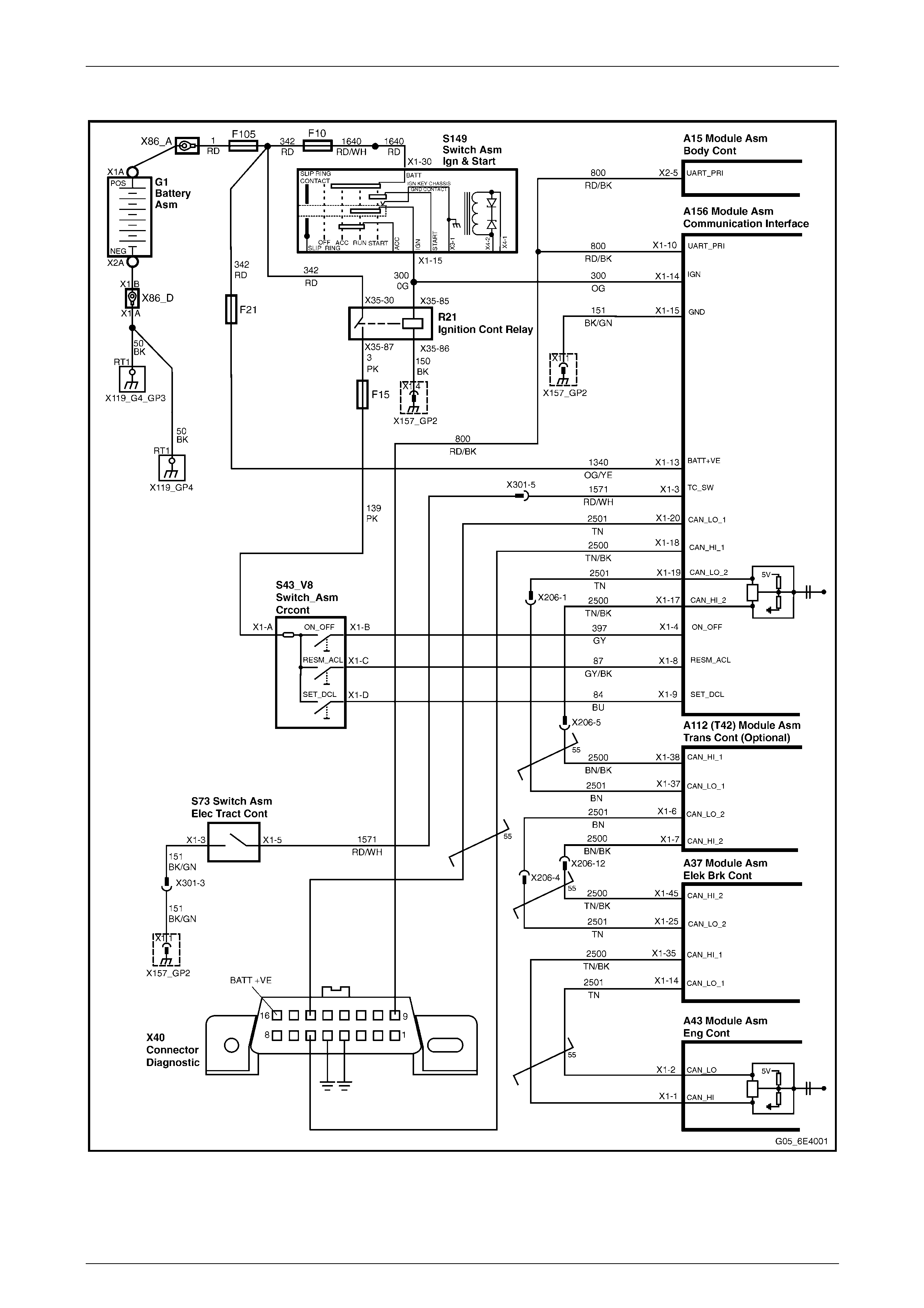
Powertrain Interface Module – HSV – Gen IV V8 Page 6E4–56
Page 6E4–56
With Automatic Transmission
Figure 6E4 – 13
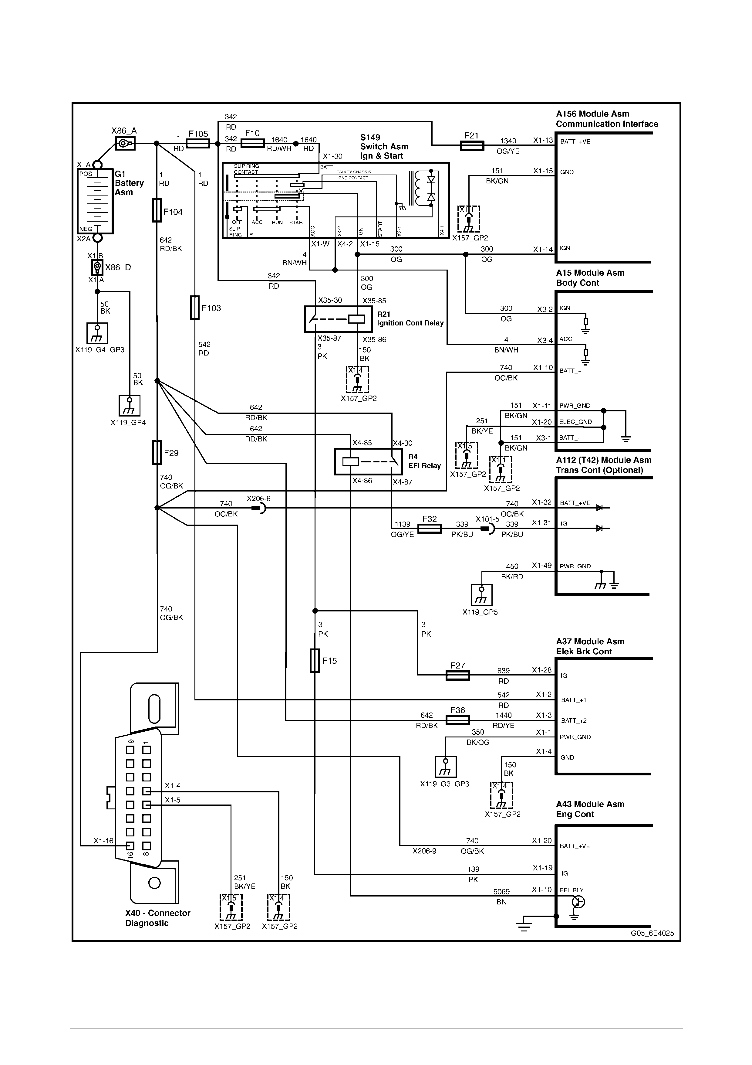
Powertrain Interface Module – HSV – Gen IV V8 Page 6E4–57
Page 6E4–57
8.2 Power and Ground Distribution Circuit
Figure 6E4 – 14
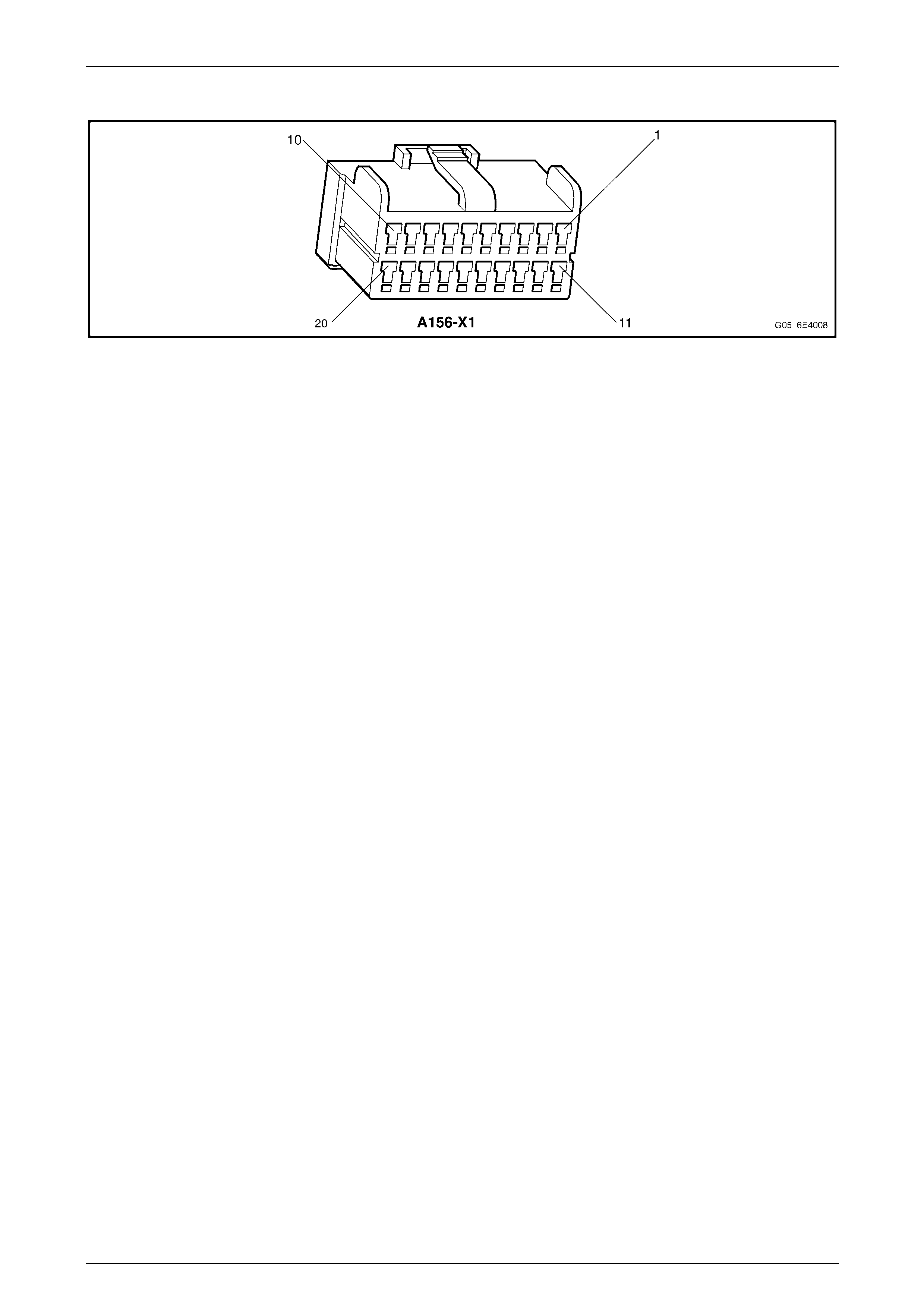
Powertrain Interface Module – HSV – Gen IV V8 Page 6E4–58
Page 6E4–58
PIM Connector Pin Specifications
Figure 6E4 – 15
Pin Description
1 Not Connected 11 Not Connected
2 Not Connected 12 Not Connected
3 Traction Control Switch – Ground Signal Circuit 1571 13 12 V Uninterrupted Supply Voltage – Fuse F21
Circuit 1340
4 Cruise Control Switch On, Off or Cancel – 12 V Signal
Circuit 397 14 Ignition Supply Voltage – Circuit 300
5 Not Connected 15 Main Ground Circuit – Circuit 151
6 Not Connected 16 Not Connected
7 Not Connected 17 CAN HI 2 – Serial Data Circuit 2500
8 Cruise Control Resume or Acceleration – 12 V Signal
Circuit 87 18 CAN HI 1 – Serial Data Circuit 2500
9 Cruise Control Set or Deceleration – 12 V Signal
Circuit 84 19 CAN LO 2 – Serial Data Circuit 2501
10 UART Primary – Serial Data Circuit 800 20 CAN LO 1 – Serial Data Circuit 2501
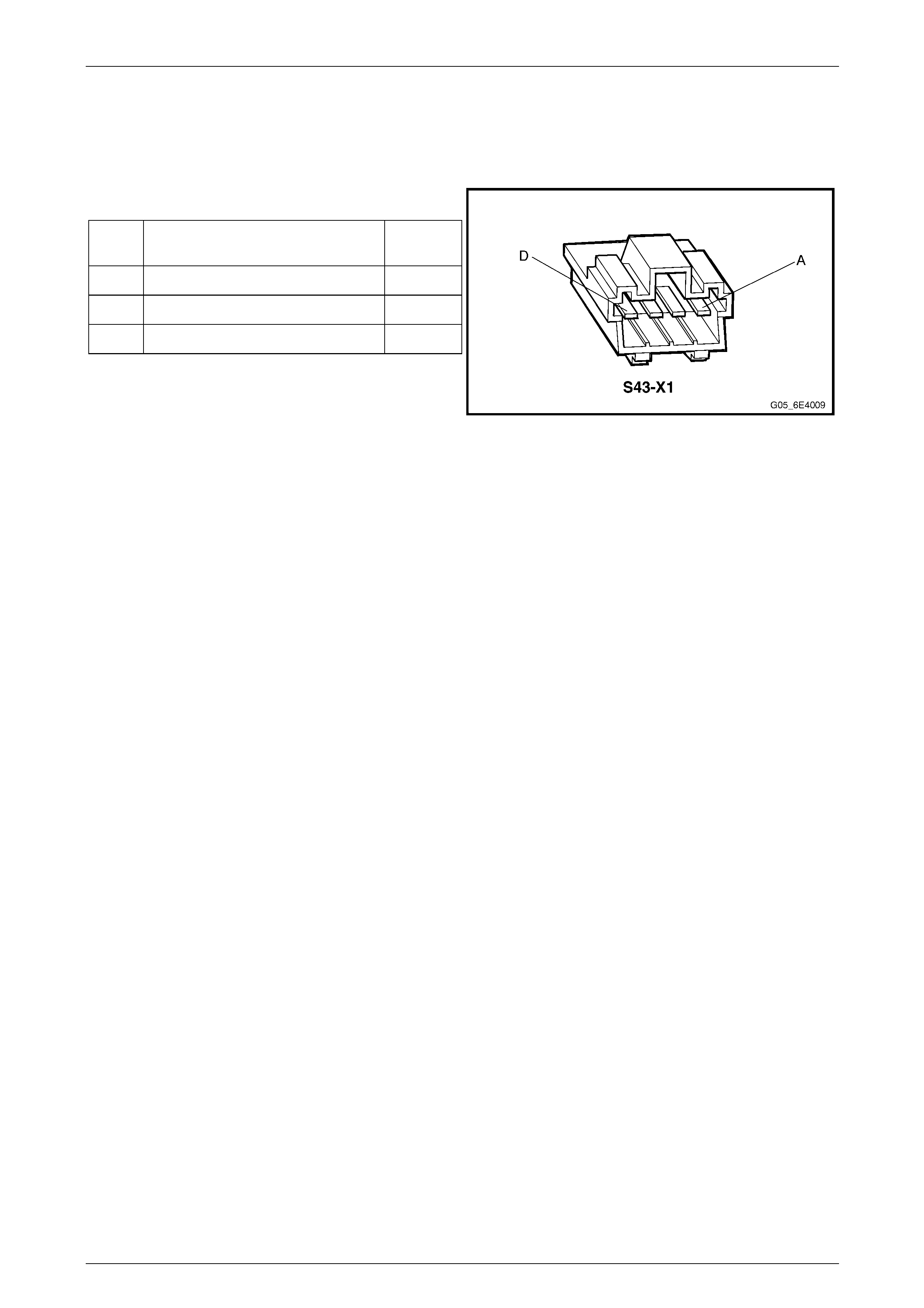
Powertrain Interface Module – HSV – Gen IV V8 Page 6E4–59
Page 6E4–59
8.3 Cruise Control Switch Assembly
Cruise Control Switch Assembly Connector Pin Specifications
Pin Description
Pin Function Circuit
Number
B On/Off Signal 397
C Resume/Accelerate Signal 87
D Set/Decelerate Signal 84
Figure 6E4 – 16
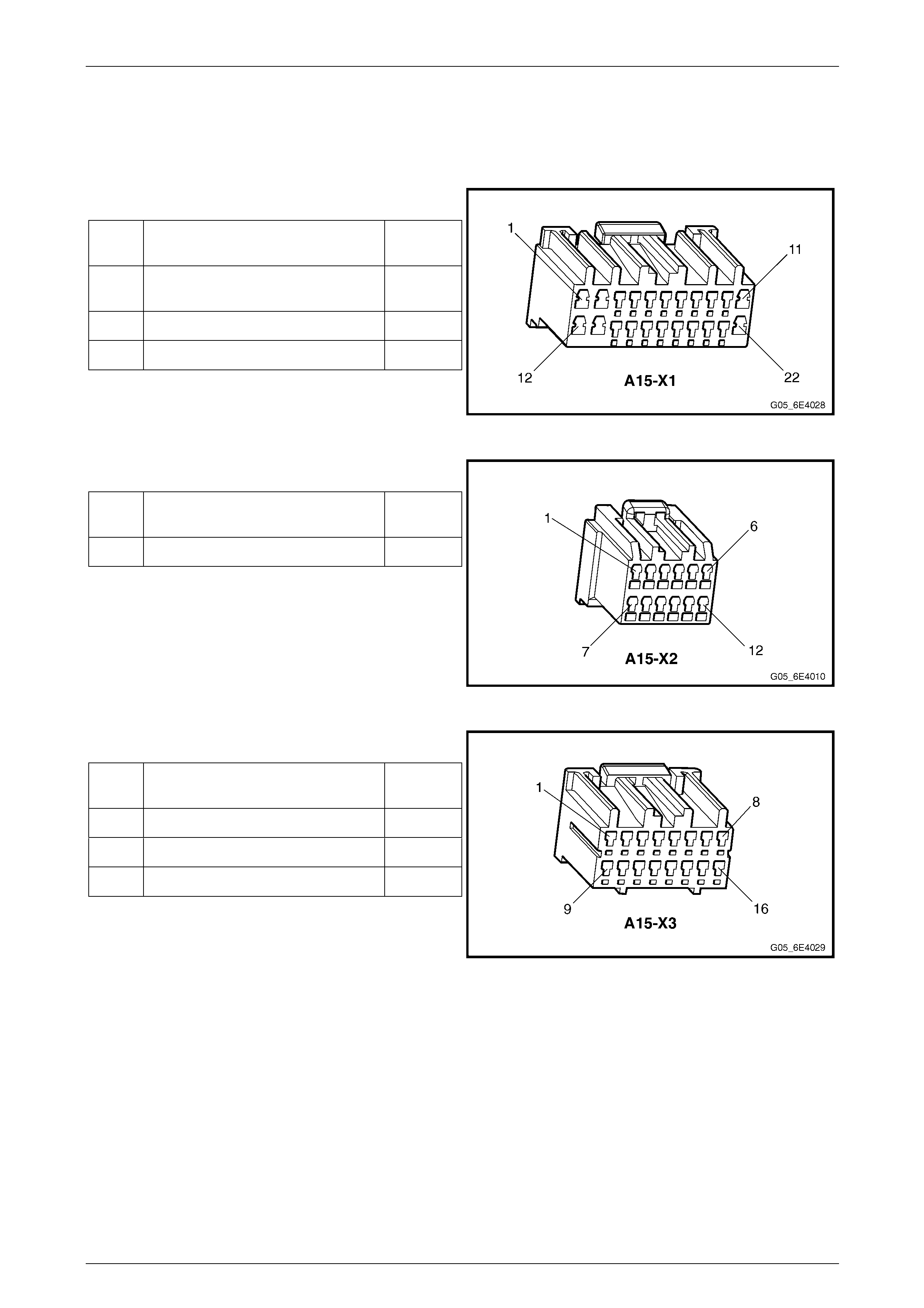
Powertrain Interface Module – HSV – Gen IV V8 Page 6E4–60
Page 6E4–60
8.4 Body Control Module
Body Control Module Connector Pin Specification
Pin Description – Connector X1
Pin Function Circuit
Number
10 12 V Uninterrupted Supply Voltage
– Fuse F29 740
11 Main Ground Circuit 151
20 Main Ground Circuit 251
Figure 6E4 – 17
Pin Description – Connector X2
Pin Function Circuit
Number
5 UART Serial Data 800
Figure 6E4 – 18
Pin Description – Connector X3
Pin Function Circuit
Number
1 Main Ground Circuit 151
2 Ignition Supply Voltage 300
4 Ignition Supply Voltage – Accessory 4
Figure 6E4 – 19
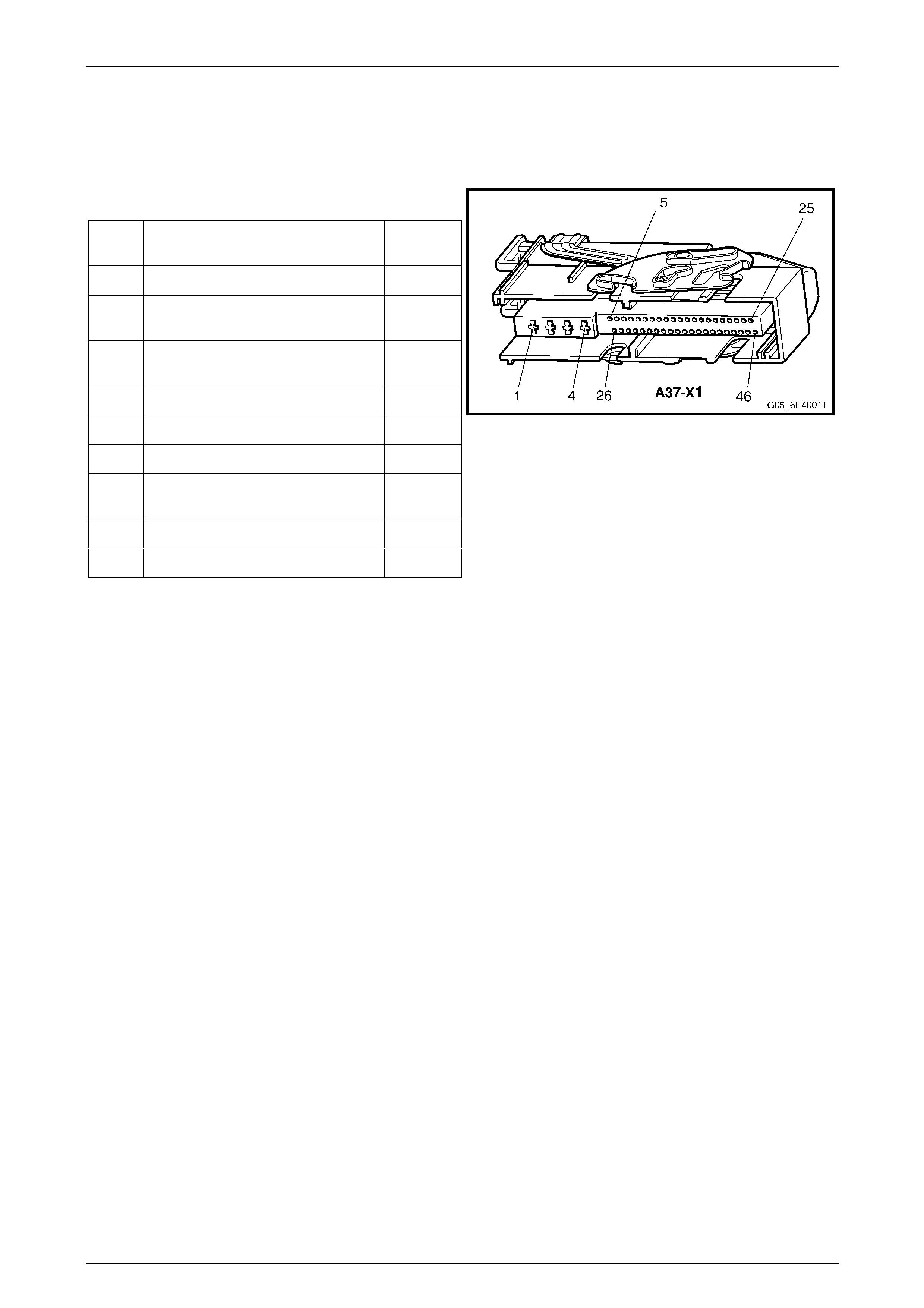
Powertrain Interface Module – HSV – Gen IV V8 Page 6E4–61
Page 6E4–61
8.5 ABS-TCS Electronic Control Unit
ABS-TCS Electronic Control Unit Connector Pin Specifications
Pin Description
Pin Function Circuit
Number
1 Main Ground Circuit 350
2 12 volts Uninterrupted Supply
Voltage – Fuse 103 542
3 12 volts Uninterrupted Supply
Voltage – Fuse 36 1440
4 Ground – ECU Ground Circuit 150
14 CAN LO 1 - Serial Data 2501
25 CAN LO 2 - Serial Data 2501
28 Switched Battery Voltage From
Ignition Control Relay 839
35 CAN HI 1 - Serial Data 2500
45 CAN HI 2 - Serial Data 2500
Figure 6E4 – 20
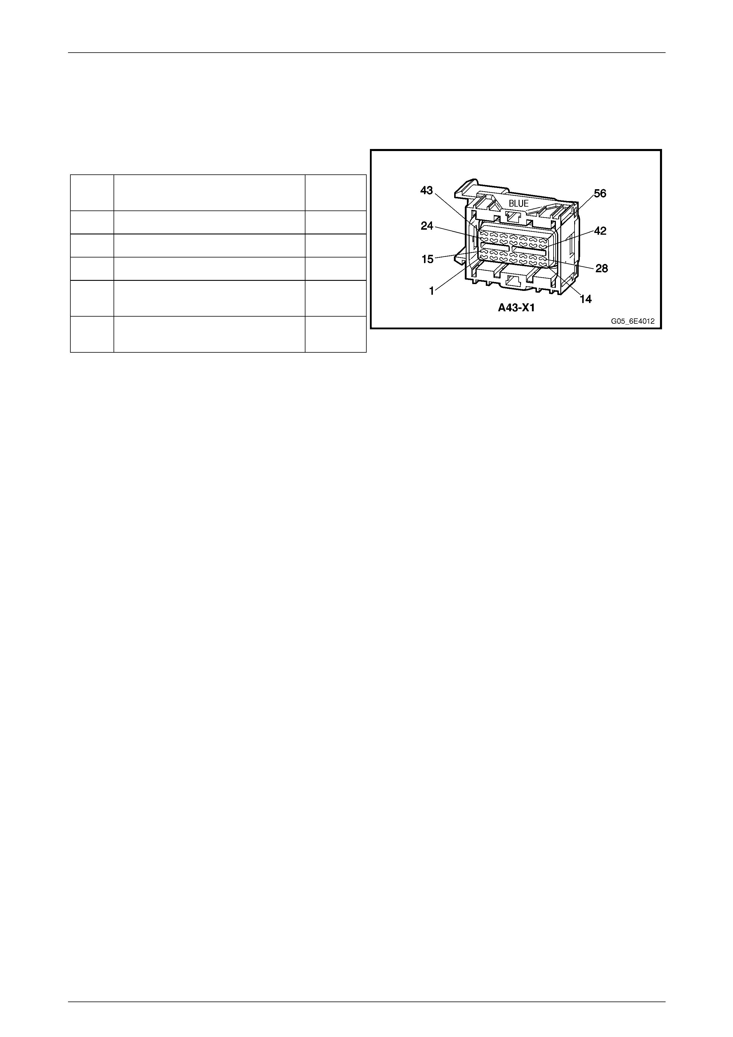
Powertrain Interface Module – HSV – Gen IV V8 Page 6E4–62
Page 6E4–62
8.6 Engine Control Module
Engine Control Module Connector Pin Specifications
Pin Description
Pin Function Circuit
Number
1 CAN HI - Serial Data 2500
2 CAN LO - Serial Data 2501
10 EFI Relay Control 5069
19 Switched Battery Voltage From
Ignition Control Relay – F15 139
20 12 volts Uninterrupted Supply
Voltage – Fuse 29 740
Figure 6E4 – 21
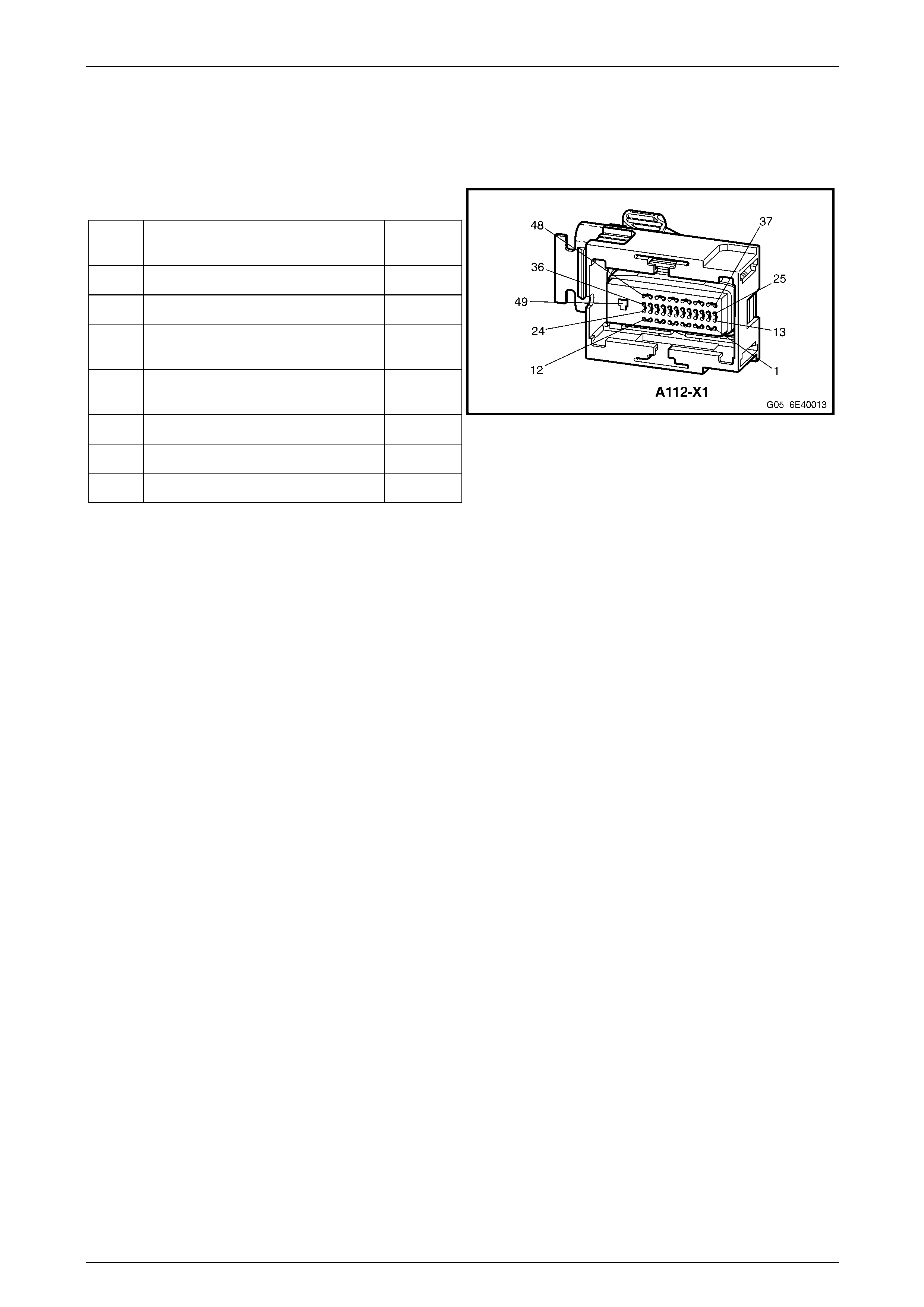
Powertrain Interface Module – HSV – Gen IV V8 Page 6E4–63
Page 6E4–63
8.7 Automatic Transmission Control Module
Automatic Transmission Control Module Connector Pin Specifications
Pin Description
Pin Function Circuit
Number
6 CAN LO 2 - Serial Data 2501
7 CAN HI 2 - Serial Data 2500
31 Switched Battery Voltage From EFI
Relay – F32 339
32 12 volts Uninterrupted Supply
Voltage – Fuse 29 740
37 CAN LO 1 - Serial Data 2501
38 CAN HI 1 - Serial Data 2500
49 Main Ground Circuit 450
Figure 6E4 – 22
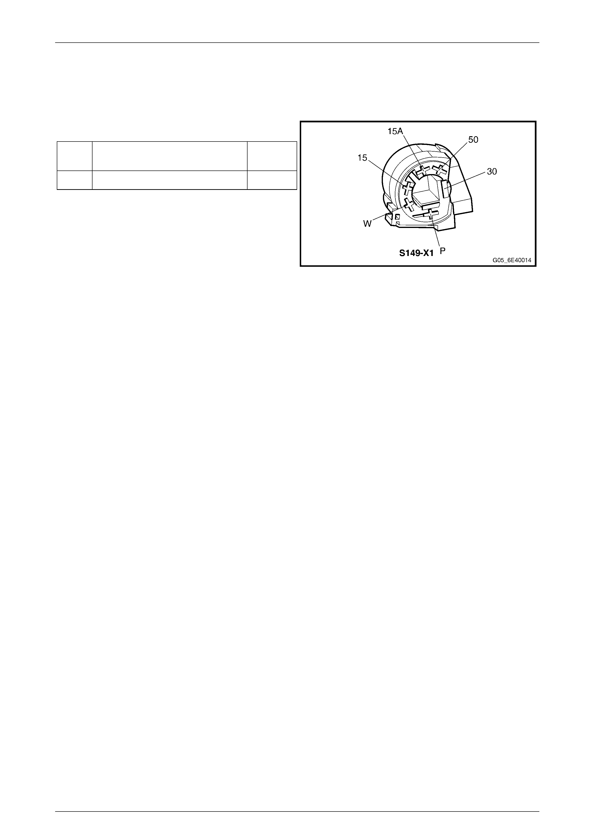
Powertrain Interface Module – HSV – Gen IV V8 Page 6E4–64
Page 6E4–64
8.8 Ignition Switch
Ignition Switch Connector Pin Specification
Pin Description
Pin Function Circuit
Number
15 Ignition 300
Figure 6E4 – 23
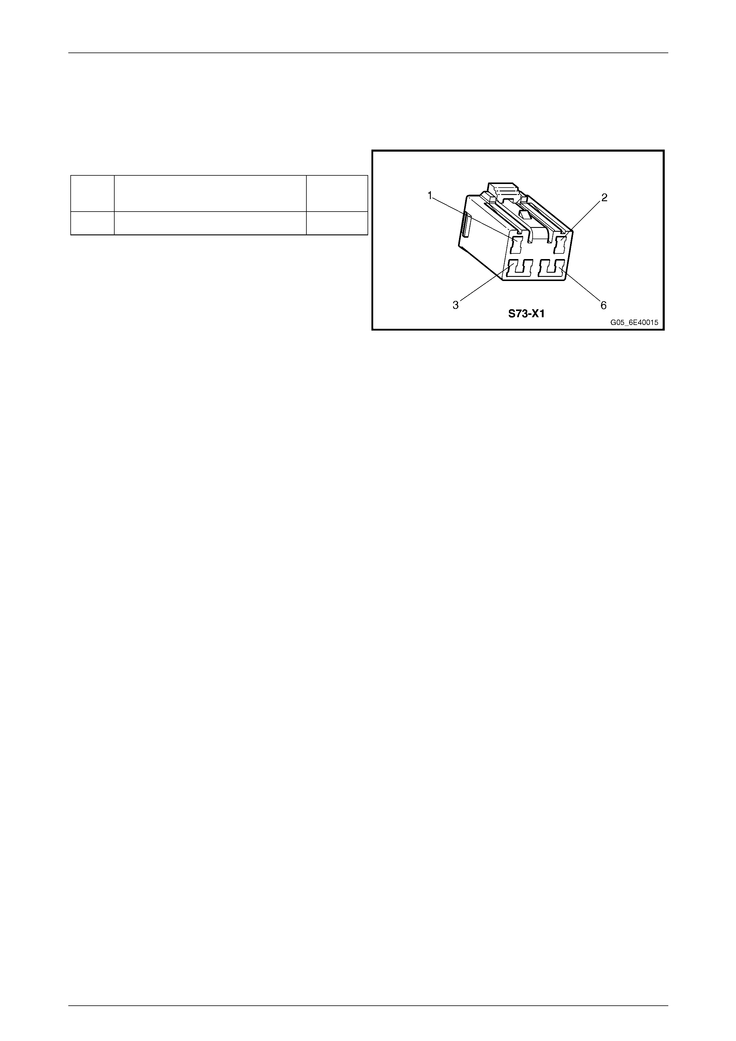
Powertrain Interface Module – HSV – Gen IV V8 Page 6E4–65
Page 6E4–65
8.9 Traction Control Switch
Traction Control Switch Connector Pin Specifications
Pin Description
Pin Function Circuit
Number
5 Traction Control - Signal Circuit 1571
Figure 6E4 – 24

Powertrain Interface Module – HSV – Gen IV V8 Page 6E4–66
Page 6E4–66
9 Service Operations
9.1 Safety and Precautionary Measures
The following safety and precautionary
measures must be followed when servicing
and diagnosing the powertrain interface
module (PIM) System. Otherwise, personal
injury and/or improper braking system
operation may occur:
• Whenever welding with electric welding equipment, disconnect the wiring harness connector from the PIM.
• Never disconnect or reconnect the PIM wiring harness connector when the battery is connected or the ignition is
switched ON.
• Do not touch the PIM connector pins or soldered components on the PIM circuit board to prevent possible
Electrostatic Discharge damage.
• To avoid wiring connector ter m inal damage, always use suitable wiring harness test leads (such as those in Tool
No, J35616) when performing tests on the PIM wiring connector.
• The PIM is extremely sensitive to Electro-Magnetic Interfere nce (EMI). Ensure that the PIM wiring harness is routed
correctly and securely fitted to mounting clips when performing service procedures.
• Due to the sensitive nature of the PIM circuitry, specific wiring repair procedures have be en developed. These
procedures and instructions ar e detailed in 12P Wiring Diag rams and are the only recommended and approved
wiring repair methods.
• Ensure that all wiring harness connectors are seated correctly.
• Never disconnect the battery from the vehicle electrical system while the engine is running.
• Always disconnect the battery from the vehicle electrical system before ch arging.
• Do not use a fast charger for starting the vehicle.
• Ensure the battery cable terminals ar e secure.
• Before installing a new PIM, ensure the correct type is fitted. Always refer to the latest spare parts information.
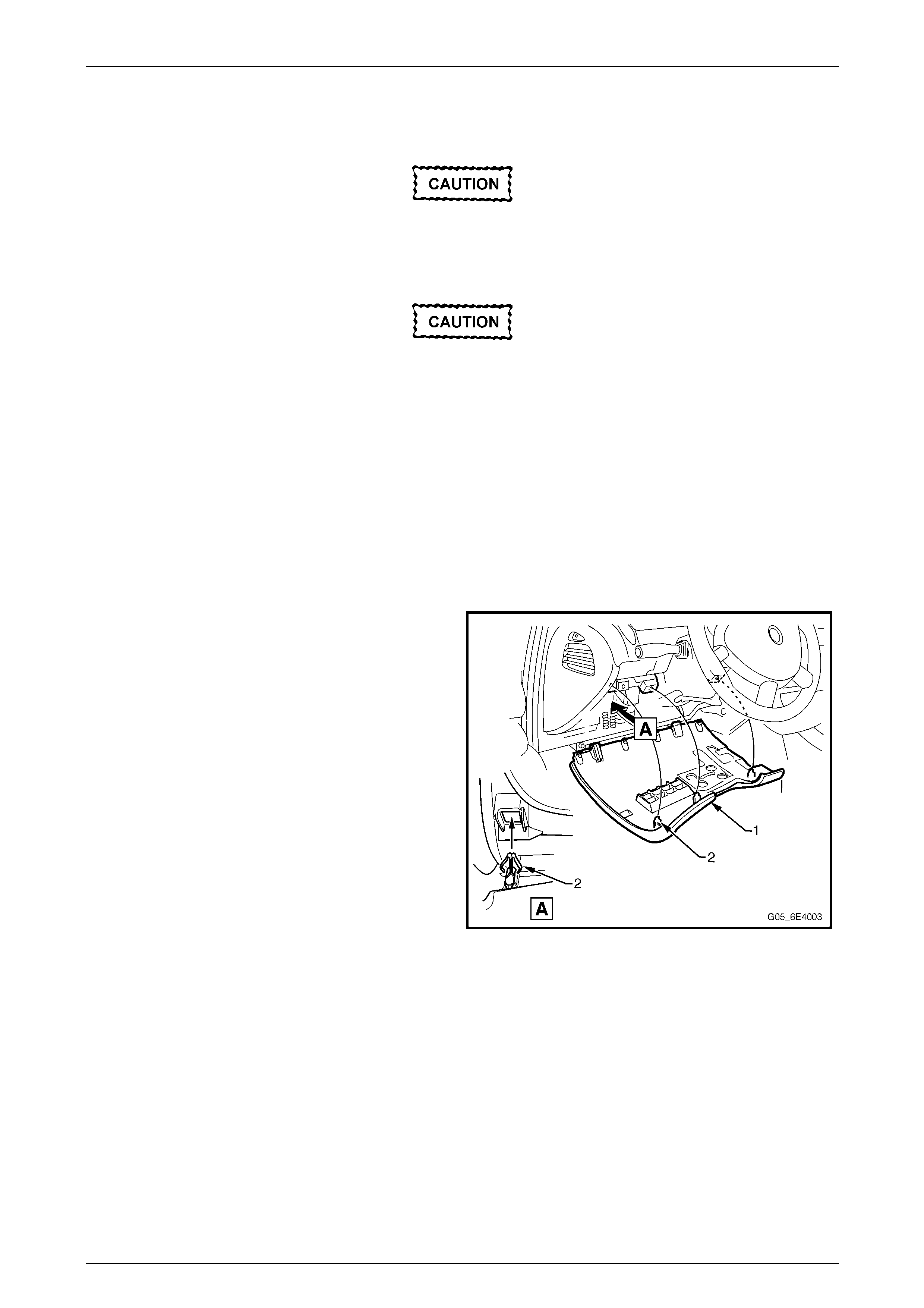
Powertrain Interface Module – HSV – Gen IV V8 Page 6E4–67
Page 6E4–67
9.2 Pow ertrain Interface Module
Do not touch the powertrain interface module
pins as Electro static Discharge (ESD) damag e
may result. For further information on ESD,
refer to Section 00 Cautions and Notes.
When replacing the PIM, the PIM must be
reset prior to removal. Failure to perform this
procedure will result in the inability to:
• Test the PIM for warrant y purp oses.
• Install the PIM into other vehicles.
Remove
1 If replacing the PIM, reset the PIM prior to PIM removal. Refer to PIM Reset in this section.
2 Turn the ignition switch off.
3 Remove Fuse F21, refer to Section 12O Fuses, Relays and Wiring Harnes ses .
4 Grasp the upper edge of the i nstrument panel lower
trim panel assembly (1) and pull outwards to
disengage the three retaini ng clips (2).
5 Swing the panel assembly open.
Figure 6E4 – 25
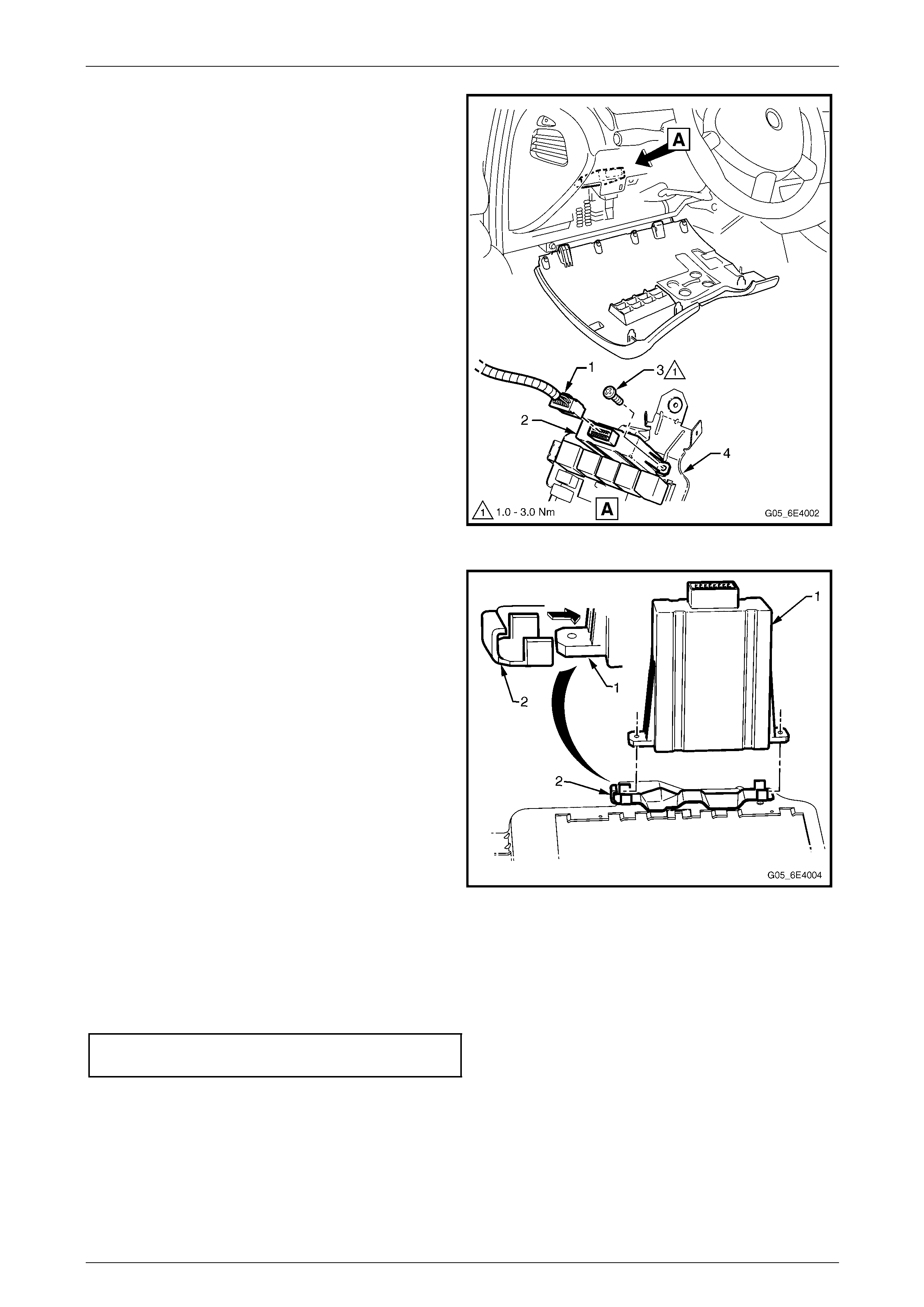
Powertrain Interface Module – HSV – Gen IV V8 Page 6E4–68
Page 6E4–68
6 Disconnect the wiring harness connector (1) from the
powertrain interface module (PIM) (2).
7 Remove the screw (3) attaching the PIM to the
steering column bracket outer brace (4).
Figure 6E4 – 26
8 Slide the PIM (1) in the direction of the arrow to
disengage the PIM from the mounting bracket (2).
NOTE
To aid in the removal of the PIM, it may be
necessary to detach the fuse and relay block
from the steering column bracket outer brace,
refer to Section 1A3 Instrument Panel and
Console.
Figure 6E4 – 27
Reinstall
Reinstallation of the PIM is the reverse of the removal procedure, noting the following:
1 Tighten the attaching screw to the correct torque specification.
PIM attaching screw
torque specification..................................... 1.0 - 3.0 Nm
2 If the PIM has been replaced, perform the following procedures:
• PIM service programming, refer to 10.4 BCM Link to ECM.
• PIM Configuration, refer to 10.3 PIM Configuration.
• Main diagnostic functional check, refer to 5.2 Main Diagnostic Table.
3 Road test the vehicle and check for correct vehicle operation.
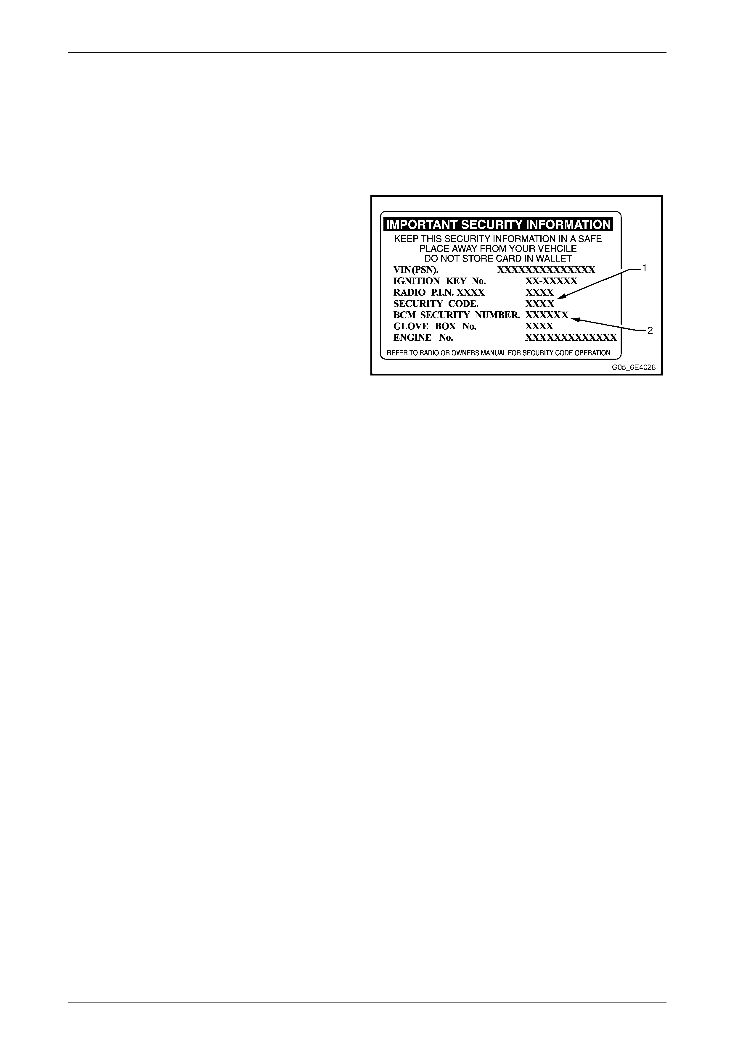
Powertrain Interface Module – HSV – Gen IV V8 Page 6E4–69
Page 6E4–69
10 PIM Security and Programming
10.1 Security and Programming Information
Vehicle Security Card
When performing certain powertrain interface module (PIM)
programming functions using Tech 2, you may be prompted
to enter a four digit Security Code (1) a nd /or BCM six digit
Security Number (2). This information is found on the
vehicle security card issued with the vehicle when new. If
the card is unavailable, contac t the Holden Technical
Assistance (TAS) centre to obtain the relevant Security
Code and BCM security number.
Figure 6E4 – 28
Security Code
The security code is required when performing certai n PIM, BCM and ECM programming functions. When Tech 2
requests the security code to be entered, and an incorrect code is entered, the PIM will go into a security wait time stage.
This wait time stage will prevent any further attempts to enter the securit y code until the wait time has elapsed.
Should a second incorrect se curity code be entered after the initial wait time has elapsed, the PIM will go into a second
wait time stage. The wait time will increase each time an incorrect code is entered. When the correct code is entered the
wait time will reset back to its original value of 10 seconds.
NOTE
The ignition switch must be in the ON position
with the battery connected during the wait time
period.
The wait time stages are as follows:
• Stage 1 = 10 seconds.
• Stage 2 = 10 seconds.
• Stage 3 = 10 minutes.
• Stage 4 = 20 minutes.
• Stage 5 = 40 minutes.
• Stage 6 = 80 minutes.

Powertrain Interface Module – HSV – Gen IV V8 Page 6E4–70
Page 6E4–70
Tech 2 PIM Security Information Data List
The Tech 2 PIM Security Information Data List displays the PIM's current security status.
To view the data list:
1 Connect Tech 2 to the data link connector (DLC) a nd turn on the ignition .
2 On Tech 2 select Body / Powertrain Interface Module / Security / Security Information.
NOTE
The Tech 2 PIM Security Information Data List
typical display values are obtained from a
correctly operating vehicle under the following
conditions:
• ignition switched on,
• engine not running, and
• vehicle is stationary.
Tech 2 Parameter Units Displayed Typical Display Values
BCM / PIM Status Yes / No Yes
Security Code Programmed Yes / No Yes
Security Wait Time Inactive / Active Inactive
Security Wait Time Inactive / 0:00:00 Inactive
Security Code Correct Enter Yes / No Yes
Security Code Reset Counter 0 0

Powertrain Interface Module – HSV – Gen IV V8 Page 6E4–71
Page 6E4–71
10.2 PIM Reset Procedure
Do not perform the reset procedure within
sixty seconds of turning on the ignition.
Failure to comply may result in the PIM failing
to reset.
When a PIM has been installed into a vehicle, it is security linked to the body control module (BCM) and engine control
module (ECM). Once this linking has been performed, the PIM cannot be installed in any other vehicle, unless the
security linking between the BCM and the ECM has been r eset using the following procedure:
1 Prior to resetting the PIM, obtain the Security Code an d the BCM Security Number. For further information, refer to
Vehicle Security Card.
2 Connect Tech 2 to the data link connector (DLC) and turn on the ignition.
3 On Tech 2 select Body / Powertrain Interface Module / Security / Reset PIM.
NOTE
When Tech 2 requests programming approval,
obtain TIS approval. For further information on
TIS approval, refer to Section 0C Tech 2.
NOTE
If a Tech 2 screen displ a ying Security Wait Time
Active, Please Wait! appears after selecting the
Reset PIM option, an incorrect security code has
been previously entered. Refer to Security Code
and Tech 2 Security Information Data List for
further information.
4 When Tech 2 displays Enter Security Code, enter the security code, press the Enter key and then the Okay soft
key.
5 When Tech 2 displays Do you really want to Reset?, press the Reset soft key.
Do not turn off the ignition within 60 seconds
of performing the PIM reset procedure. F ailure
to comply may result in the PIM failing to
reset.
6 When Tech 2 displays Reset Completed Successfully, press the Confirm soft key to return to the Tech 2
Security screen.

Powertrain Interface Module – HSV – Gen IV V8 Page 6E4–72
Page 6E4–72
10.3 PIM Configuration
When a new PIM has been inst alled into a vehicle, vehicle specific information such as the Vehicle Identification Number
(VIN), engine type etc, must be programmed into the PIM. To program:
• a new PIM, refer to Configuring a New PIM, in this section,
• an existing PIM, refer to Configuring an Existing PIM, in this section,
• the VIN number, refer to Configuring the VIN Number, in this section.
Configuring a New PIM
Although the following procedure is specific to changing the engine type, the procedure for the remaining vehic le
parameters is identical.
1 Connect Tech 2 to the data link connector (DLC).
2 On Tech 2 select Body / Powertrain Interface Module / Program / Program ECU.
3 Using the up or down arrow selection keys, select the Engine Type.
4 Press the Modify soft key.
5 Using the up or down arrow selection keys, select V8Gen4 6.0L L52.
6 Press the Confirm soft key. Tech 2 reverts to the main Tech 2 Program ECU screen where the selection made in
the previous step is displayed .
7 Make the necessary changes for the remaining items shown in the Tech 2 Program ECU screen.
8 When finished, press the Program soft key.
9 Enter the VIN using the Tech 2 arrow selection keys.
NOTE
The left and right arrow selection keys move the
Tech 2 cursor along the VIN number, whilst the
up and down selection arrows change the
character value.
Numbers can also be entered by pressing the
number key's on Tech 2.
10 After entering the VIN, press the Enter key. The changes a re now programmed into the PIM.
Do not turn off the ignition within 60 seconds
of configuring the PIM. Failure to comply may
result in the changes failing to be
programmed into the PIM.
11 When notified the process is completed, press the Confirm soft key to return to the Tech 2 Program screen.

Powertrain Interface Module – HSV – Gen IV V8 Page 6E4–73
Page 6E4–73
Configuring an Existing PIM
Although the following procedure is specific to changing the transmission type, the procedure for changing any other
vehicle parameter is the same.
1 Connect Tech 2 to the data link connector (DLC).
2 On Tech 2 select Body / Powertrain Interface Module / Program / Program Configuration.
3 Using the up or down arrow selection keys, select the Transmission Type.
4 Press the Modify soft key.
5 Using the up or down arrow selection keys, select the appropriate transmis s ion.
6 Press the Confirm soft key. Tech 2 reverts to the main Tech 2 Program Configuration screen where the selection
made in the previous step is displa yed.
7 Make any other required changes for the remaining items.
8 When finished, press the Program soft key. The changes are now programmed into the PIM.
Do not turn off the ignition within 60 seconds
of configuring the PIM. Failure to comply may
result in the changes failing to be
programmed into the PIM.
9 When notified t he process is completed, press the Confirm soft key to return to the Tech 2 Program screen.
Programming the VIN
1 Connect Tech 2 to the data link connector (DLC).
2 On Tech 2 select Body / Powertrain Interface Module / Program / Program VIN.
3 Enter the VIN using the Tech 2 arrow selection keys.
NOTE
The left and right arrow selection keys move the
Tech 2 cursor along the VIN number, whilst the
up and down selection arrows change the
character value.
Numbers can also be entered by pressing the
number key's on Tech 2.
4 After entering the VIN number, press the Enter key. The changes are now programmed into the PIM.
Do not turn off the ignition within 60 seconds
of programming the VIN. Failure to comply
may result in the changes failing to be
programmed into the PIM.
5 When notified t he process is completed, press the Confirm soft key to return to the Tech 2 Program screen.

Powertrain Interface Module – HSV – Gen IV V8 Page 6E4–74
Page 6E4–74
10.4 BCM Link to ECM / PIM
Do not perform the BCM Link to ECM / PIM
procedure within sixty seconds of turning on
the ignition. Failure to comply may result in
the PIM failing to link.
When the powertrain interface modu le (PIM) has been replaced, it is necessary to security link the PIM to the body
control module (BCM) and engine control module (ECM) before the vehicle will start.
NOTE
This linking procedure between the ECM and PIM
is also known as the Immobiliser Function
Programming.
1 Prior to performing the linking procedure, obtain the s ecuri ty code and BCM security number. For further
information, refer to Vehicle Security Card.
2 Connect Tech 2 to the data link connector (DLC).
3 On Tech 2 select Body / Powertrain Interface Module / Security / BCM Link to ECM/PIM.
4 When Tech 2 displays BCM Replaced, press the No soft key.
5 When Tech 2 displays PIM/ECM Replaced?, press the Yes soft key.
6 When Tech 2 displays Select Engine Type use the up and down arro w selection keys to select the appropriate
engine type and then press the Enter key.
7 When Tech 2 displays Please Select, use the up and down arrow selection keys to select PIM Replaced, and then
press the Enter key.
NOTE
When Tech 2 requests programming approval,
obtain TIS approval. For further information on
TIS approval, refer to Section 0C Tech 2.
8 When Tech 2 displays BCM Security No., enter the BCM security number, press the Enter key.
9 When Tech 2 displays Turn Ignition Off!, switch off the ignition.
10 When Tech 2 displays Turn Ignition On, switch on the ignition.
11 When Tech 2 displays Enter Security Code, enter the security code and press the Enter key and then the Okay
soft key.
12 When Tech 2 displays Confirm Security Co d e, re-enter the security code, press the Enter key and then the Okay
soft key.
13 When Tech 2 displays Stop Engine – Turn Off Ignition, switch off the ignition.
14 When Tech 2 displays Turn Ignition On, switch on the ignition.
Do not turn off the ignition within 60 seconds
of performing the BCM Link to ECM/PIM
procedure. Failure to co mply may result in th e
PIM failing to link with the BCM / ECM.
15 When Tech 2 displays P ro gramming Successful, press the Confirm soft key to return to the Tech 2 Security
screen.

Powertrain Interface Module – HSV – Gen IV V8 Page 6E4–75
Page 6E4–75
11 Specifications
Powertrain Interface Module Bus Cut-off Resistor....................................120 Ω
Engine Control Module Bus Cut-off Resistor............................................120 Ω

Powertrain Interface Module – HSV – Gen IV V8 Page 6E4–76
Page 6E4–76
12 Torque Wrench Specifications
Powertrain Interface Module Attaching Screw...............................1.0 – 3.0 Nm
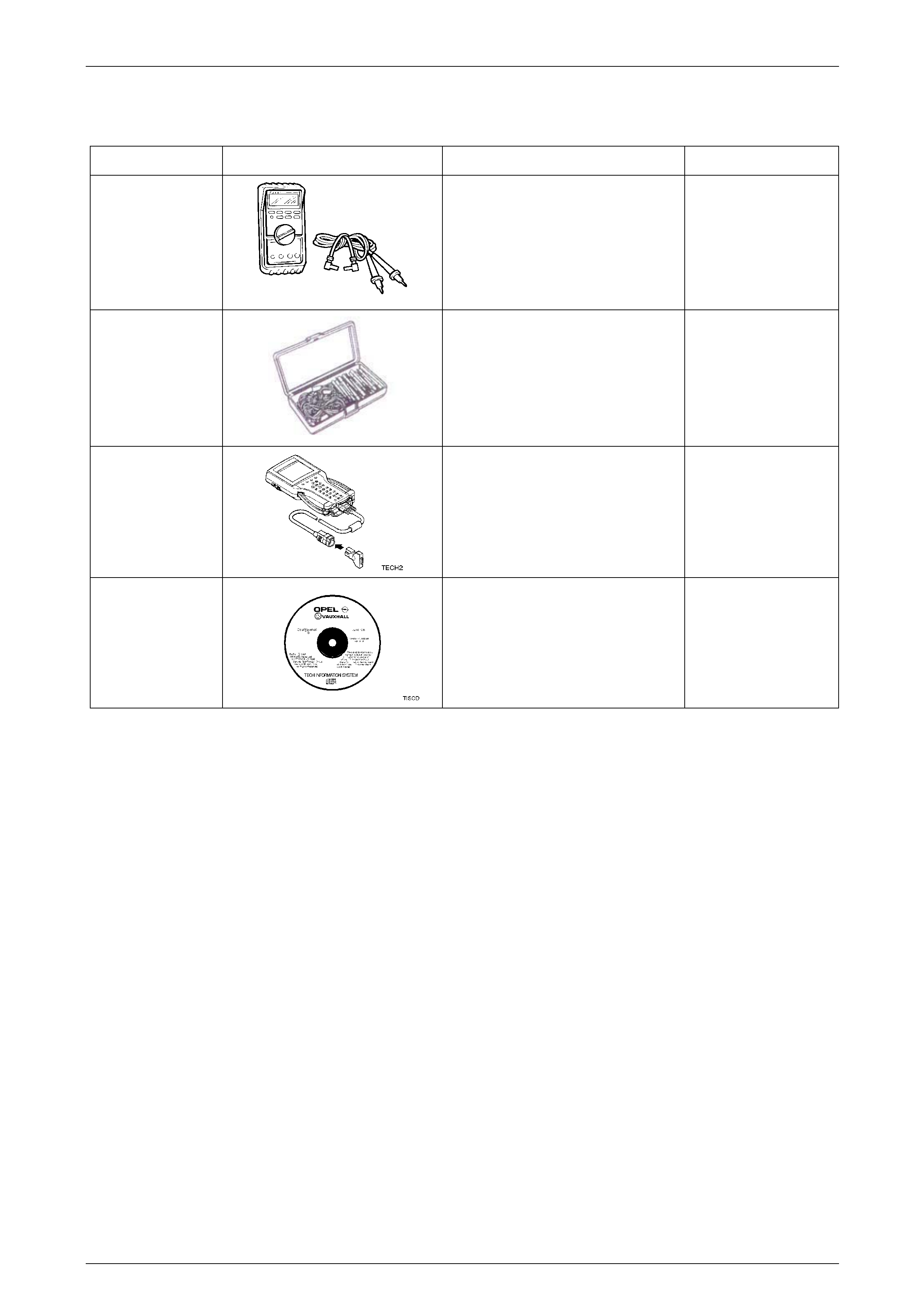
Powertrain Interface Module – HSV – Gen IV V8 Page 6E4–77
Page 6E4–77
13 Special Tools
Tool Number Illustration Description Tool Classification
3588
Digital Multimeter
Also Previously released as J 39200 or
equivalent.
NOTE: The instrument must have 10
mega ohms impedanc e and be
capable of reading frequencies.
Mandatory
J35616
Connector Test Adaptor Kit
Used when carrying out electric al
diagnostic circuit checks.
Desirable
70000861
Tech 2 Diagnostic Scan Tool
Previously released.
Mandatory
N/A
Technical Information System (TIS)
CD ROM
Available to Authorised Dealers.
Mandatory