
Body Page B-1
Section B
Body
ATTENTION
HSV vehicles are equipped with a Supplemental Restraint System (SRS). An SRS consists of seat belt pre-
tensioners (fitted to all front seats), a dri ver’s-side air bag , a passenger’s-sid e air bag and left and right hand
side air bags. Refer to CAUTIONS, Section 12M Occupant Protection System in the MY 2005 VZ Coupe Series
Service Information before performing any service operation on or around SRS components, the steering
mechanism or wiring. Failure to follow the CAUTIONS could result in personal injury or unnecessary SRS
system repairs.
1 Purpose...................................................................................................................................................2
2 General Information ...............................................................................................................................3
3 Body General Service Information .......................................................................................................4
4 Seats........................................................................................................................................................5
VZ Coupe Trim Cover Assemblies ....................................................................................................................... 9
VZ Coupe Seat Pad Assemblies Front And Rear................................................................................................ 9
VZ Coupe Seat Assemblies................................................................................................................................. 10
VZ Coupe Frame Assemblies.............................................................................................................................. 10
5 Body Ornamentation............................................................................................................................11
5.1 Body Styling Package ......................................................................................................................................... 11
5.2 Paint Protectors................................................................................................................................................... 13
6 Rear Spoiler ..........................................................................................................................................24
6.1 Service Operations.............................................................................................................................................. 24
Spoiler Ends......................................................................................................................................................... 24
Removal........................................................................................................................................................... 24
Installation........................................................................................................................................................ 24
Spoiler Centre Section ........................................................................................................................................ 24
Removal........................................................................................................................................................... 24
Installation........................................................................................................................................................ 24
6.2 HSV Coupe Rear Spoiler – New Rear Quarter Panel and New Spoiler............................................................28
Decklid Centre Spoiler Outer Holes ................................................................................................................... 28
Centre Spoiler Centre Holes ............................................................................................................................... 29
Side Spoiler Upper Attaching Holes................................................................................................................... 29
Side Spoiler Lower Attaching Hole .................................................................................................................... 30
De-burring and Anti-corrosion Treatment ......................................................................................................... 32
Sealing.................................................................................................................................................................. 32
General Precaution.............................................................................................................................................. 32
Techline

Body Page B-2
1 Purpose
The purpose of this section is to provide information on the body and body components fitted to HSV VZ Coupe vehicles.
The information is designed to supplement the information contained in the Holden VZ Coupe Service Manuals, and
details are given where differences occur between the HSV models and standard Holden models. A series of instruction
drawings describe the design changes and indicate specific part numbers, fitting instructions and relevant notes for
vehicle servicing.

Body Page B-3
2 General Information
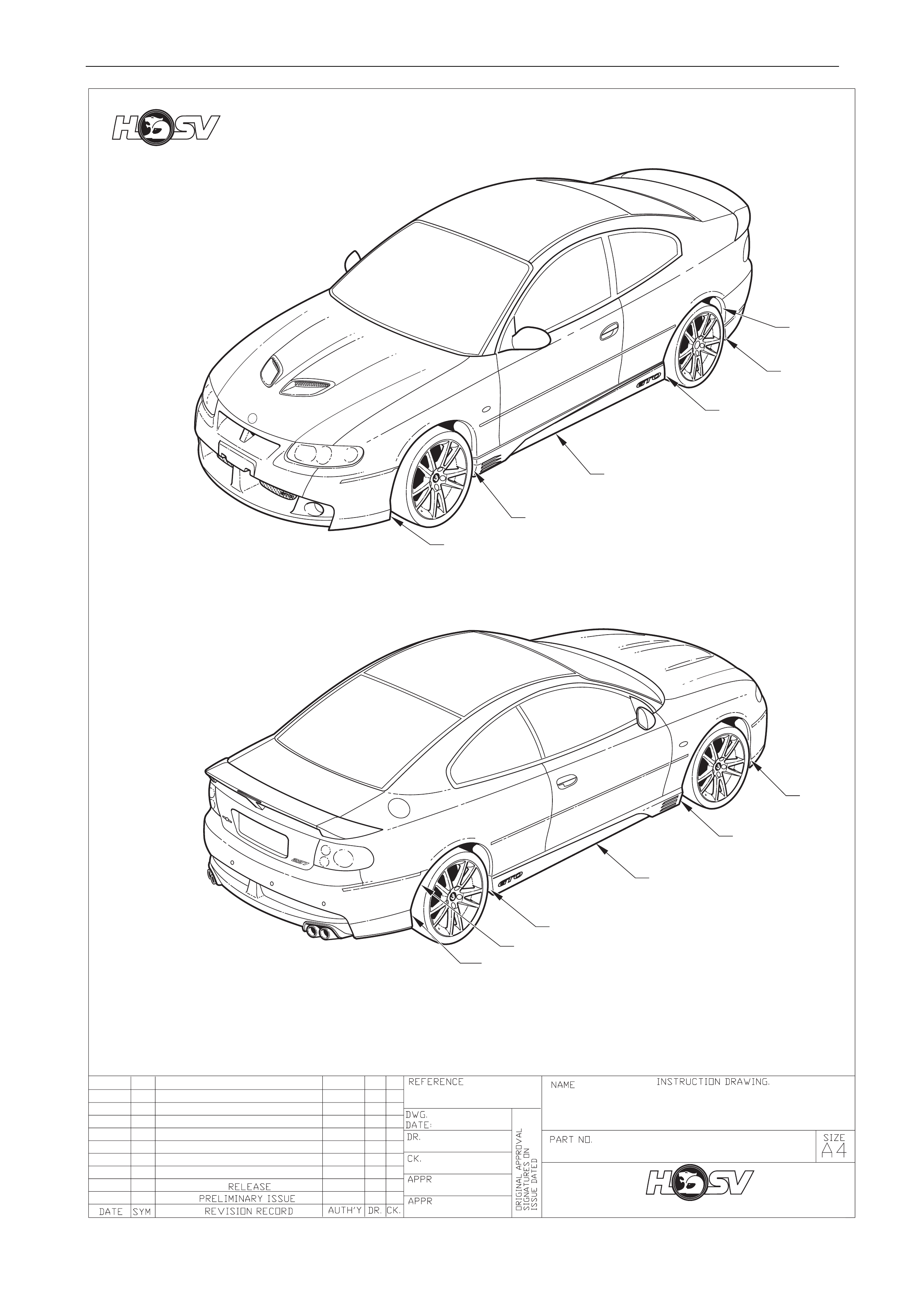
The HSV VZ Coupe is a two door variant of the HSV VZ Series Clubsport model.
The HSV VZ Coupe retains the same track and wheel base as the HSV VZ Series Clubsport, and the ma jor exterior body
sheet metal panel carry over from the Holden VZ Coupe Series models.
HSV VZ Coupe models are equipped with unique Body Side Skirts, 3-piece Rear Spoiler, Front Bumper Bar Fascia and
Rear Bumper Bar Fascia.
For all body dimensions refer to Section 1A2 Body Dimensions of the Holden MY2005 VZ Series Models Service
Information.
Body Page B-4
3 Body General Service
Information
For all body dimensions refer to Section 1A2 Body Dimensions of the Holden MY2005 VZ Series Models Service
Information.
For all body components not unique to HSV refer to Section 1A2 Body Dimensions of the Holden MY2005 VZ Series
Models Service Information.
The HSV VZ Coupe is equipped with unique Body Side Skirts, Front Bumper Facia, and 3 piece Rear Spoiler.
It is recommended that before any body repa irs be undertaken that the components involved be carefully inspected to
gain a clear understanding as to their design.
This should include attachi ng methods, assembly margins, painted features and paint accents.
Inspect the components using the relev ant HSV service instruction drawings as reference.
Where practical digital photographs can taken as required prior to work commencing, these could b e of assistance a
latter date to be used during reassembl y.
Relevant attachment tightening torque values are shown on HSV service instruction drawings. The torque locations are
defined as a number in a triangle besi de the attachment, this relates to the torque value shown on the lower margin of
the drawing.
Typical example of torque symbol location
NOTE
If specific technical data on a HSV model is not
contained in this supplement, obtain data for that
model from the relevant Holden VZ Coupe
Service Manual Supplement. References are
made throughout this section to Holden Service
Manuals, to assist in providing information for
specific service operations.
When hoisting (or jacking) HSV models,
ensure that the lifting h ead o f th e hoist lifts on
the chassis before the arm of the hoist
contacts the side-skirt
2

Body Page B-5
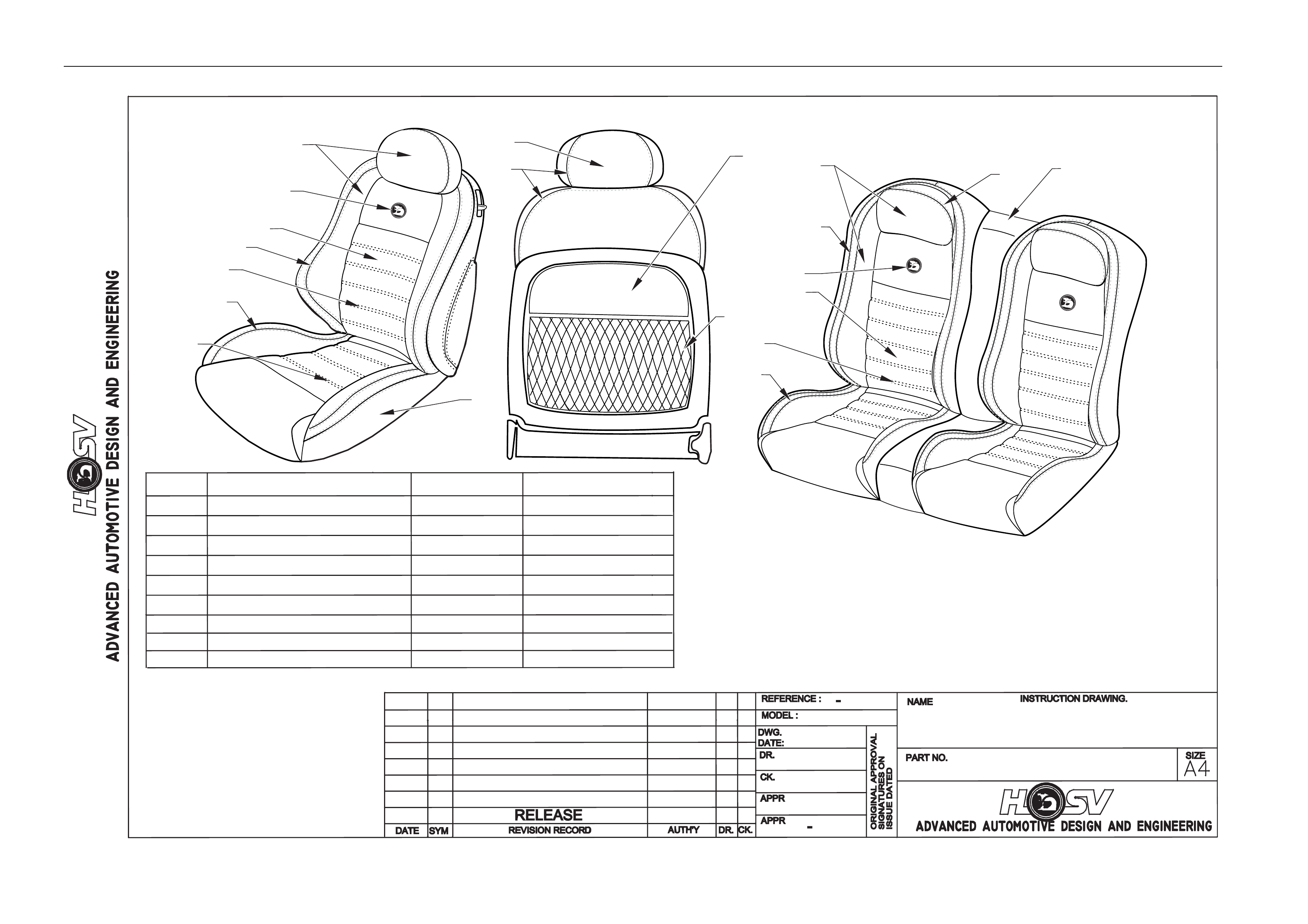
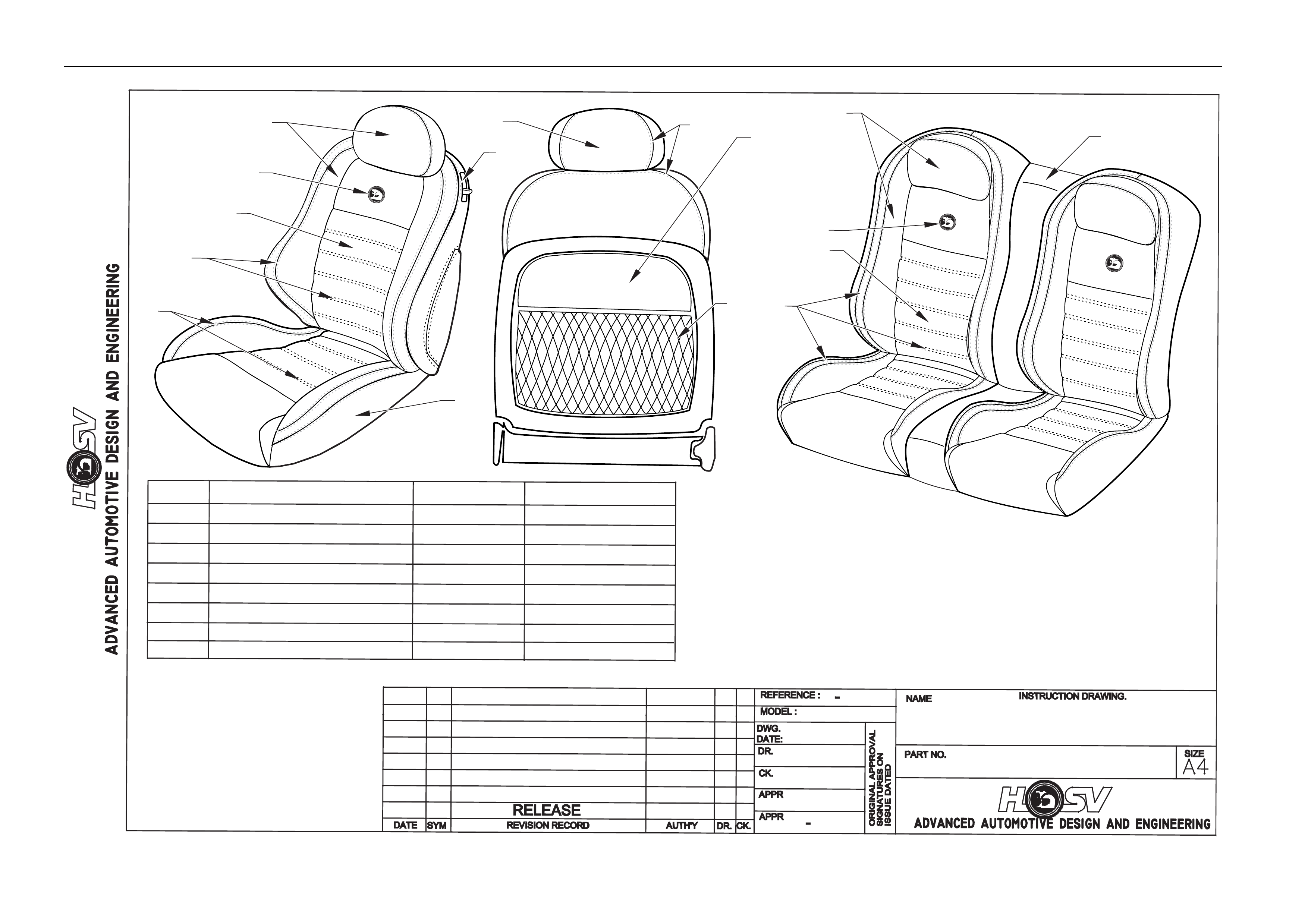
4 Seats
The HSV VZ Series Coupes are fitted with exclusive seat designs.
The HSV VZ Coupe seats have specific seats covered in model-specific trim material.
A full range of replacement parts is available for each specific HSV seat item.
Body Page B-6
AP
DP
GD
03I-040006
SEATING OPTIONS GTO COUPE
ANTHRACITE LEATHER
VZ COUPE
13/10/04
11
9
1
2
4
5
6
66
7
7
7
7
7
7
2
3
3
8
EMBOSSED
LEATHER
LEATHER
LEATHER
N/A
VINYL
COMP PLASTIC
BLACK ANTHRACITE
BLACK ANTHRACITE
BLACK ANTHRACITE
ANTHRACITE
ANTHRACITE
ANTHRACITE
ANTHRICITE
SILVER GREY
M20
M20
NETTING
BOLSTER
REAR SEAT CENTRE PANEL
ITEM PART NAME MATERIAL COLOUR
INSERT
LION / HELMET LOGO
SEAT PLASTICS
BACK COVER
STITCHING THREAD
STITCHING THREAD
MAP POCKET
1
2
3
4
5
6
7
8
9
Body Page B-7
AP
DP
GD
03I-040007
SEATING OPTIONS GTOCOUPE
DEVIL YELLOW LEATHER
VZ COUPE
13/10/04
111
7
8
2
4
5
5
6
66
6
2
3
3
EMBOSSED
LEATHER
LEATHER
LEATHER
N/A
VINYL
COMP PLASTIC
DEVIL YELLOW
DEVIL YELLOW
BLACK ANTHRACITE
ANTHRACITE
ANTHRACITE
BLAZING YELLOW
ANTHRICITE
M20
NETTING
BOLSTER
REAR SEAT CENTRE PANEL
ITEM PART NAME MATERIAL COLOUR
INSERT
LION / HELMET LOGO
SEAT PLASTICS
BACK COVER
STITCHING THREAD
MAP POCKET
1
2
3
4
5
6
7
8

Body Page B-8
AP
DP
GD
03I-040008
SEATING OPTIONS GTO COUPE
INDIANA RED LEATHER
VZ COUPE
13/10/04
111
7
8
2
4
5
5
6
66
6
2
3
3
EMBOSSED
LEATHER
LEATHER
LEATHER
N/A
VINYL
COMP PLASTIC
INDIANA RED
INDIANA RED
INDIANA RED
BLACK ANTHRACITE
ANTHRACITE
ANTHRACITE
ANTHRICITE
M20
NETTING
BOLSTER
REAR SEAT CENTRE PANEL
ITEM PART NAME MATERIAL COLOUR
INSERT
LION / HELMET LOGO
SEAT PLASTICS
BACK COVER
STITCHING THREAD
MAP POCKET
1
2
3
4
5
6
7
8

Body Page B-9
VZ Coupe Trim Cover Assemblies
T CVR FSC T CVR FSB
RH T CVR FSB
LH T CVR FRT
H/REST T CVR RSC T CVR RSB
RH T CVR RSB
LH T CVR
REAR
H/REST
1 92176466
4106466 GTO COUPE
LEATHER (MU) 4102143MU 4102144MU 4102145MU 4102146MU 4102147MU 4102148MU 4102149MU 4102150MU
2 92176463
4106463 GTO COUPE
LEATHER (NK) 4102143NK 4102144NK 4102145NK 4102146NK 4102147NK 4102148NK 4102149NK 4102150NK
3 92176465
4106465 GTO COUPE
LEATHER (ID) 4102143ID 4102144ID 4102145ID 4102146ID 4102147ID 4102148ID 4102149ID 4102150ID
VZ Coupe Seat Pad Assemblies Front And Rear
FSC
PAD FSB
PAD FRT
H/REST
PAD ASS.
RSC
PAD RSB
PAD
ASS. RH
RSB
PAD
ASS.
REAR
H/REST
PAD
ASS.
1 92176466
4106466 GTO COUPE
LEATHER (MU) 4003612 4005137 4004438 4003176 4003177 4003177 4003616
2 92176463
4106463 GTO COUPE
LEATHER (NK) 4003612 4005137 4004438 4003176 4003177 4003177 4003616
3 92176465
4106465 GTO COUPE
LEATHER (ID) 4003612 4005137 4004438 4003176 4003177 4003177 4003616

Body Page B-10
VZ Coupe Seat Assemblies
FS ASS. RH FS ASS. LH RSC ASS. RSB ASS.
1 92176466
4106466 GTO COUPE LEATHER (MU) 4102214 4102215 4102216 4102217
2 92176463
4106463 GTO COUPE LEATHER (NK) 4102210 4102211 4102212 4102213
3 92176465
4106465 GTO COUPE LEATHER (ID) 4102218 4102219 4102220 4102221
VZ Coupe Frame Assemblies
FSC
FRAME
ASM.
FSB
FRAME
ASM. RH
FSB
FRAME
ASM. LH
RSC
FRAME
ASM.
RSB
FRAME
ASM.
1 92176466
4106466 GTO COUPE LEATHER (MU) 4004611 4005736 4005735 4005124 4005123
2 92176463
4106463 GTO COUPE LEATHER (NK) 4004611 4005736 4005735 4005124 4005123
3 92176465
4106465 GTO COUPE LEATHER (ID) 4004611 4005736 4005735 4005124 4005123

Body Page B-11
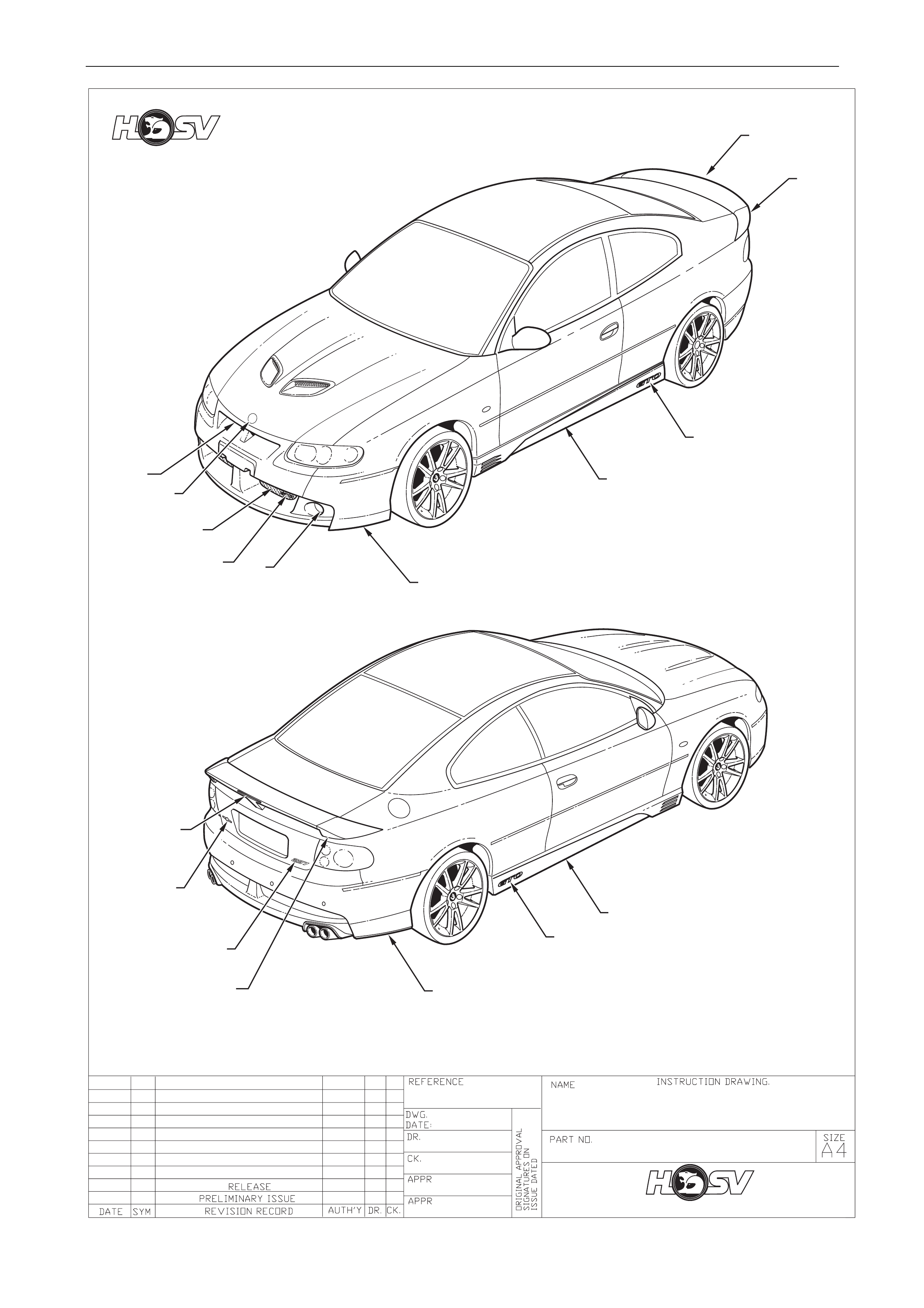
5 Body Ornamentation
HSV models are fitted with HSV specific dec als and badges to identify each model and powertrain option. This exclus ive
HSV ornamentation is positioned in exact locations on each HSV model. The ornamentation for each mode l is specified
by part number in this section. Accurate dimensions are also provided to assist with replacement of these parts.
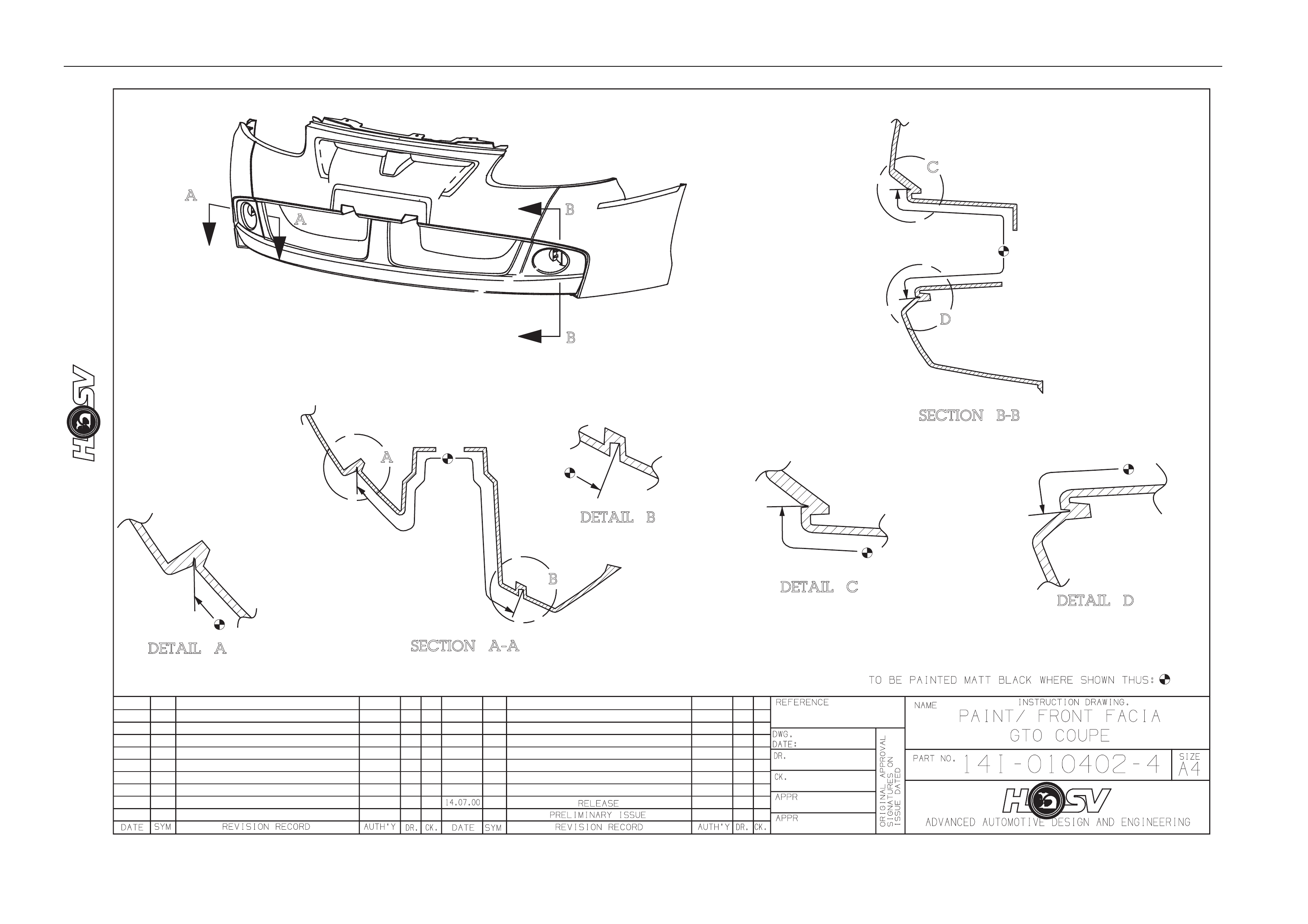
5.1 Body Styling Package
PART No QTY DESCRIPTIONS REF
14A1031101 1 FACIA-FRT BUMPER BAR 1
14a1041108 1 FACIA-RR BUMPER BAR 2
A08-021101 1 SKIRT-ROCKER LH 3
A08-021102 1 SKIRT -ROCKER RH 4
E08-020801P 1 SPOILER CENTRE DECKLID 5
E08-021103 1 SPOILER-RR DECKLID, LHS, TYPE 2 6
E08-021102 1 SPOILER-22 DECKLID, RHS, TYPE 2 7
B08-020407B8 1 HOOD BADGE LION HELMET 8
13C-031101 1 BADGE-GTO, GRILLE 9
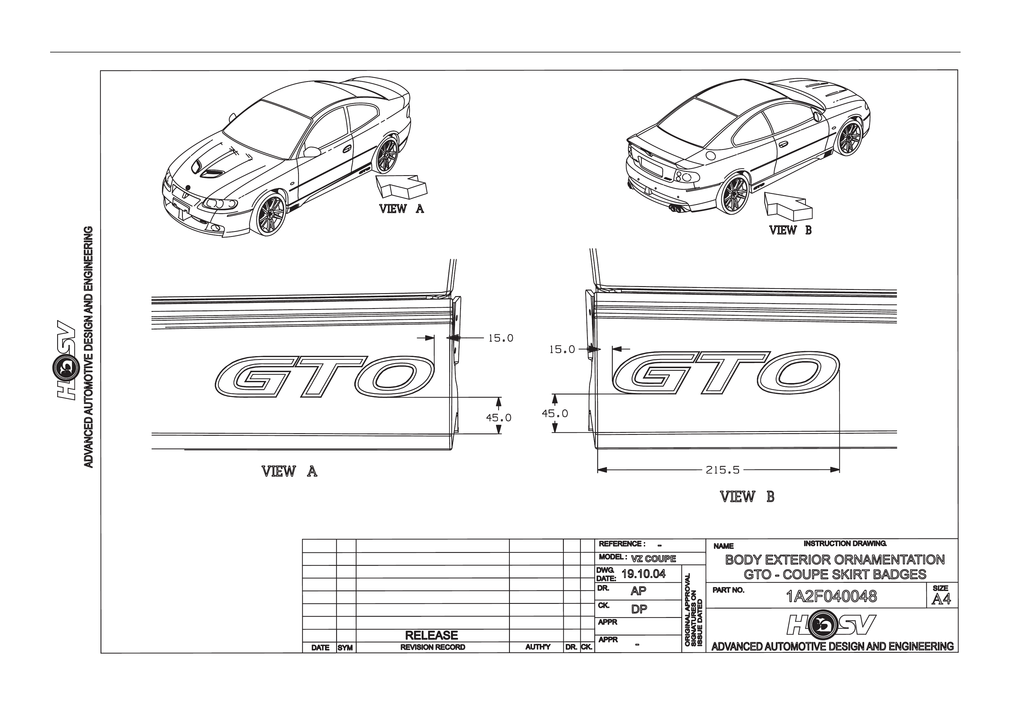
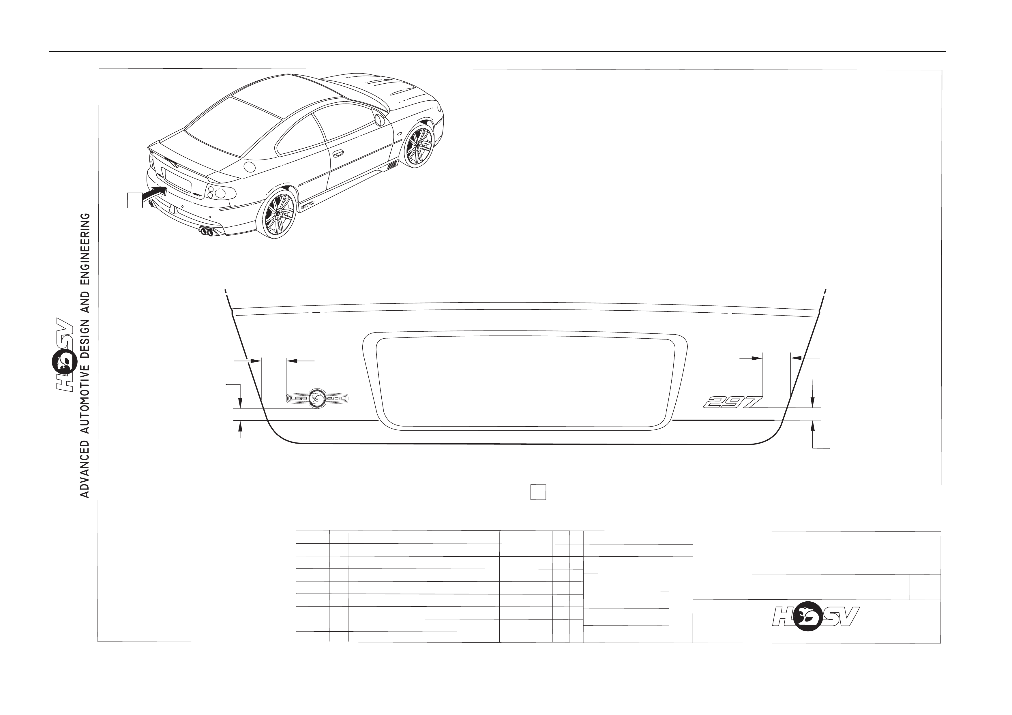
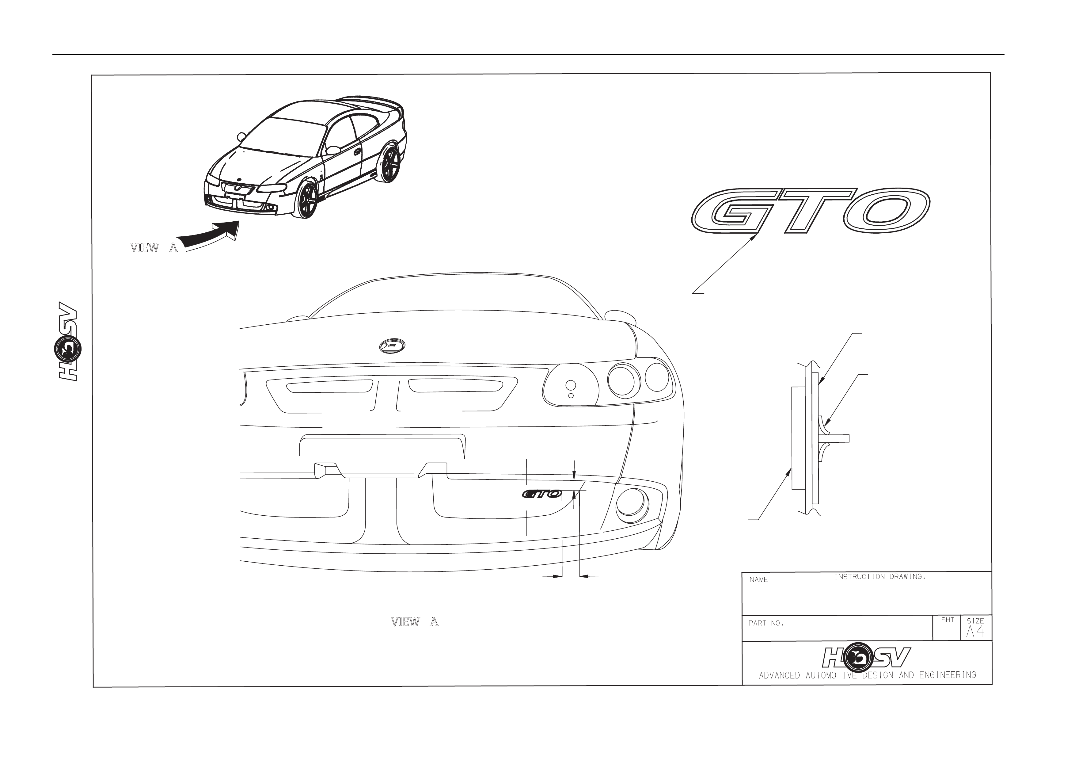
E08-021106 2 BADGE – GTO 10
E08-040602 1 BADGE – 6 LITRE 11
E08-041104 1 BADGE-ENGINE ID 297 12
14A1021111 1 MESH-BUMPER BAR OPENING LOWER 13
14A1021110 1 MESH-BUMPER BAR OPENING UPPER 14
12E-031105 1 LAMP ASM-HIGH MOUNT STOP LIGHT 15
12C-000601 1 LAMP-FOG LH & RH 16
Body Page B-12
12.10.04
DP
AP
BODY EXTERIOR ORNAMENTATON
ADVANCED AUTOMOTIVE DESIGN AND ENGINEERING
VZ COUPE
1A2F040046
VZ COUPE
13
6
8
14
1
16
4
11
15
10
10
12
3
2
7
5
9

Body Page B-13
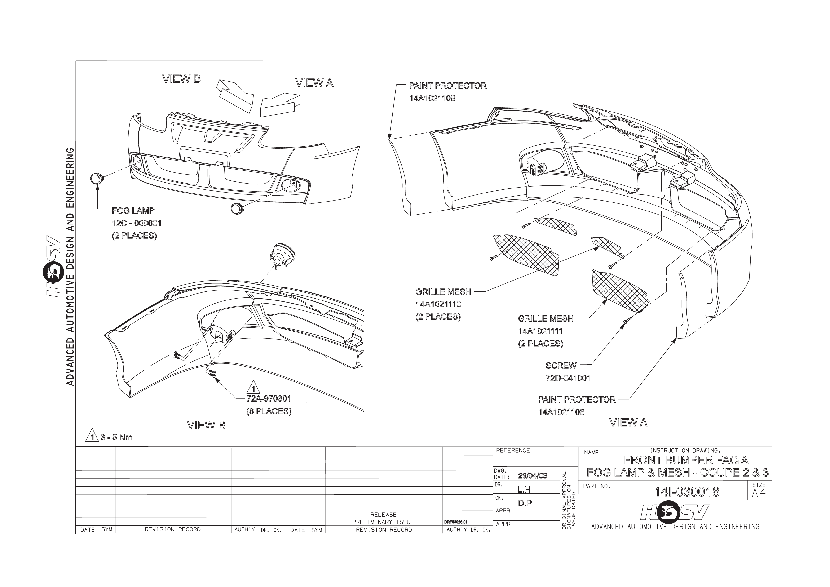
5.2 Paint Protectors
PART No QTY DESCRIPTIONS REF
14A1021109 1 PAINT PROTECTOR – FRONT LH 1
14A1021108 1 PAINT PROTECTOR – FRONT RH 2
A08-021109 1 PAINT PROTECTOR – SIDE SKIRT SIDE LH 3
A08-021110 1 PAINT PROTECTOR – SIDE SKIRT SIDE RH 4
A08-021104 1 PAINT PROTECTOR – SIDE SKIRT FRONT RH 5
A08-021103 1 PAINT PROTECTOR - SIDE SKIRT FRONT LH 6
14A2021109 1 PAINT PROTECTO R – REAR BAR LH 7
14A2021110 1 PAINT PROTECTOR - REAR BAR RH 8
A08-021106 1 PAINT PROTECTOR – SIDE SKIRT REAR RH 9
A08-021105 1 PAINT PROTECT O R – SIDE SKIRT REAR LH 10
14A2021107 1 PAINT PROTECTOR – REAR BAR UPPER LH 11
14A2021108 1 PAINT PROTECTOR – REAR BAR UPPER RH 12
Body Page B-14
12.10.04
DP
AP
BODY EXTERIOR ORNAMENTATON
ADVANCED AUTOMOTIVEDESIGNANDENGINEERING
PAINT PROTECTORS VZ COUPE
1A2F040047
VZ COUPE
1
2
4
9
10
6
7
8
12
3
11
5
Body Page B-15
VIEW B
VIEW B VIEW A
D.P
VIEW A
FOG LAMP
12C - 000601
(2 PLACES)
72A-970301
(8 PLACES)
PAINT PROTECTOR
14A1021109
PAINT PROTECTOR
14A1021108
SCREW
72D-041001
GRILLE MESH
14A1021110
(2 PLACES) GRILLE MESH
14A1021111
(2 PLACES)
FRONT BUMPER FACIA
FOG LAMP & MESH - COUPE2&3
14I-030018
L.H
29/04/03
1
3-5Nm
DRF03026.01
1
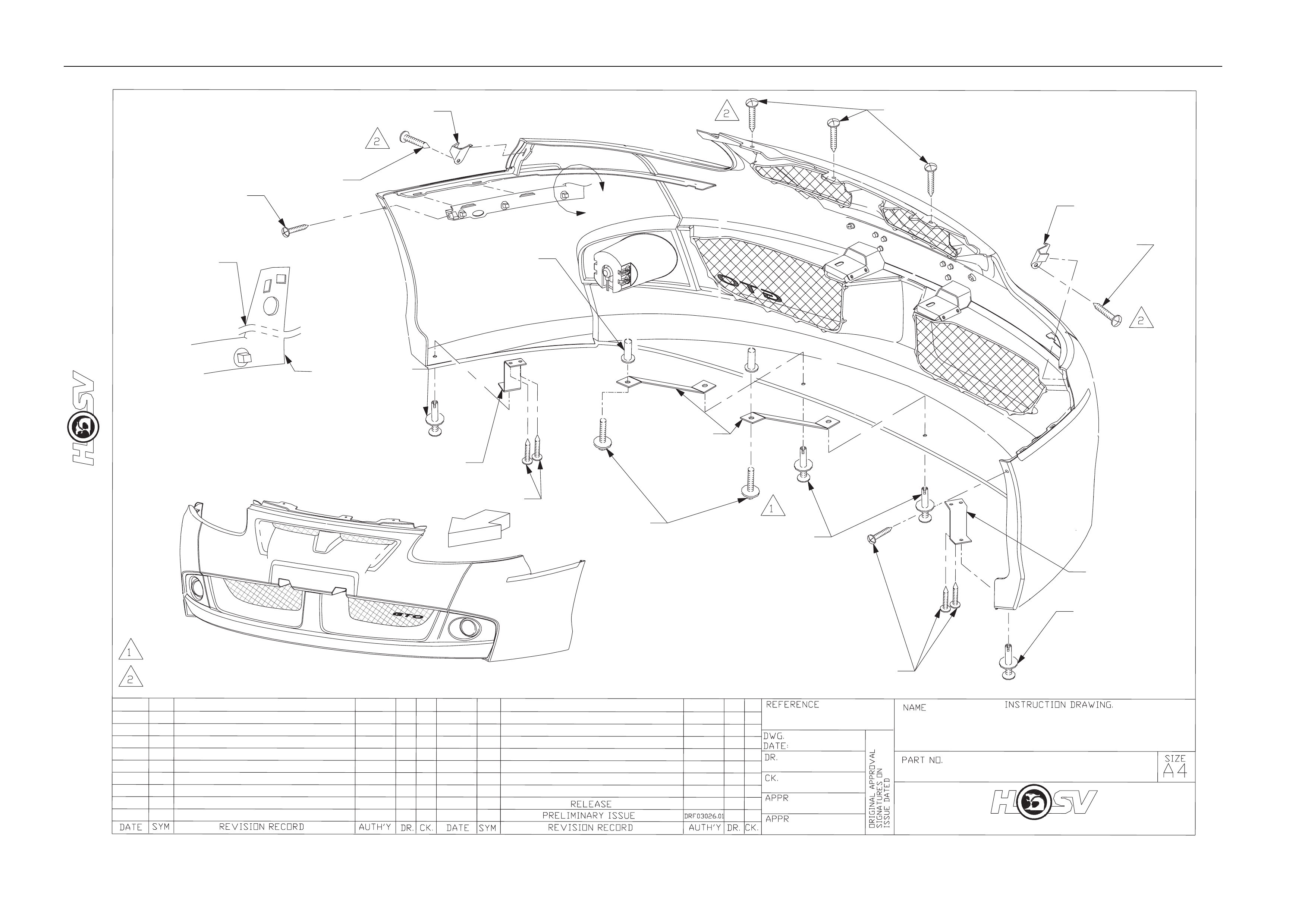
Body Page B-16
14A1021103
14A1021102
A
72D-970601
72C-671901
VIEW B
(2 PLACES)
CUT AND REMOVE
72D-970601 B
77B-691901
(2 PLACES)
70G-060001
11072643
14A1991316
FRONT BUMPER FACIA
14I-030017
ASSEMBLYCOUPE2&3
ADVANCED AUTOMOTIVE DESIGN AND ENGINEERING
72D-970601
VIEW A
77B-691901
77B-691901
14A1011102
92138377
14A1991315
11072643
LH
DP
30/04/03
3-5Nm
3-5Nm
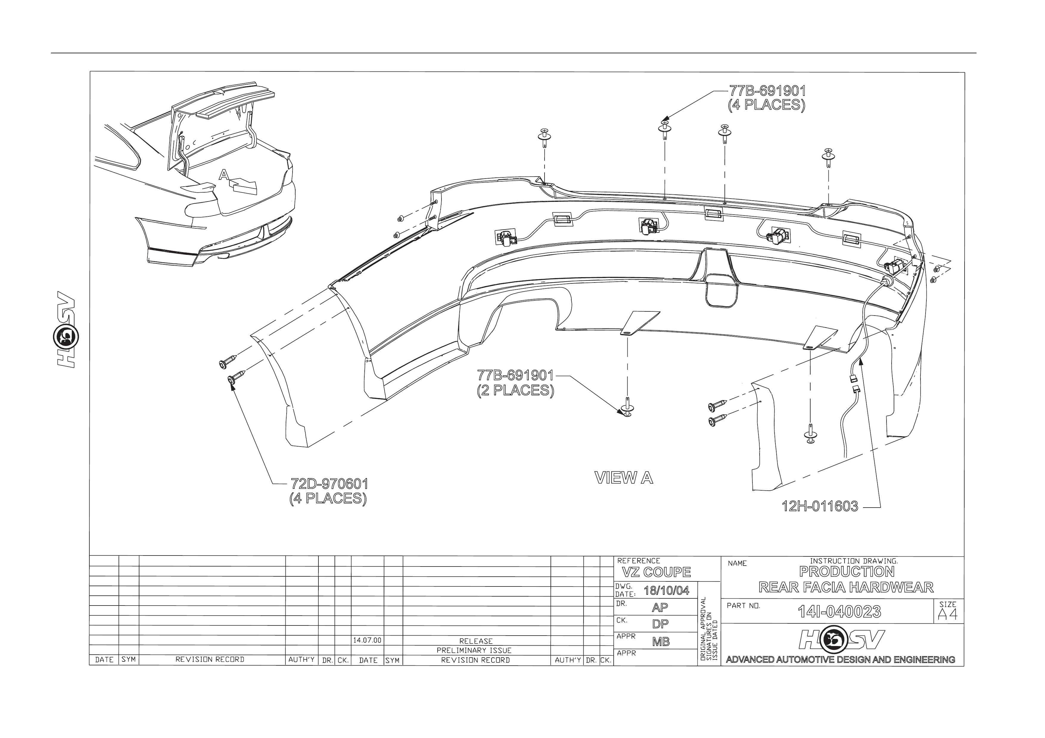
Body Page B-17
77B-691901
(2 PLACES)
72D-970601
(4 PLACES)
A
PRODUCTION
14I-040023
REAR FACIA HARDWEAR
VZ COUPE
ADVANCED AUTOMOTIVE DESIGN AND ENGINEERING
VIEW A
12H-011603
77B-691901
(4 PLACES)
DP
MB
AP
18/10/04
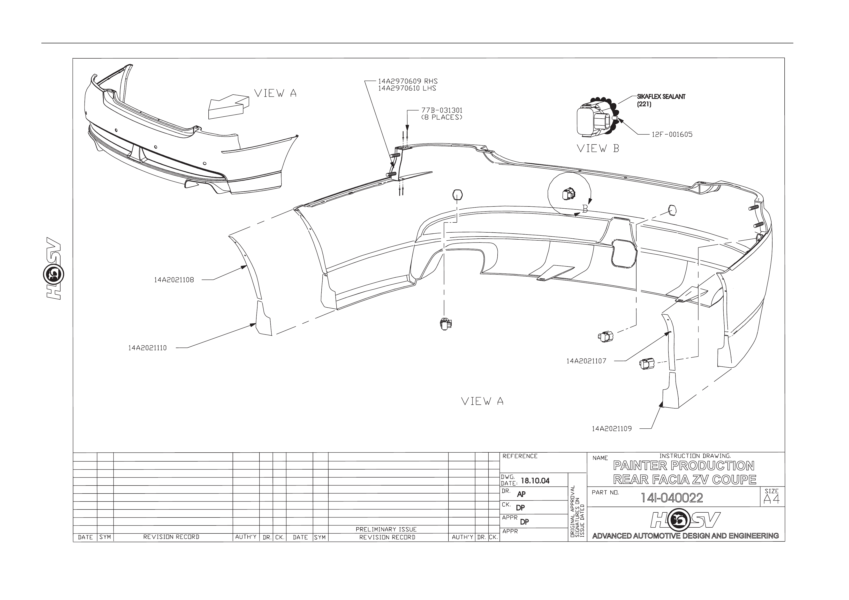
Body Page B-18
ADVANCED AUTOMOTIVE DESIGN AND ENGINEERING
SIKAFLEX SEALANT
(221)
18.10.04
AP
DP
DP
14I-040022
PAINTER PRODUCTION
REAR FACIA ZV COUPE
Body Page B-19
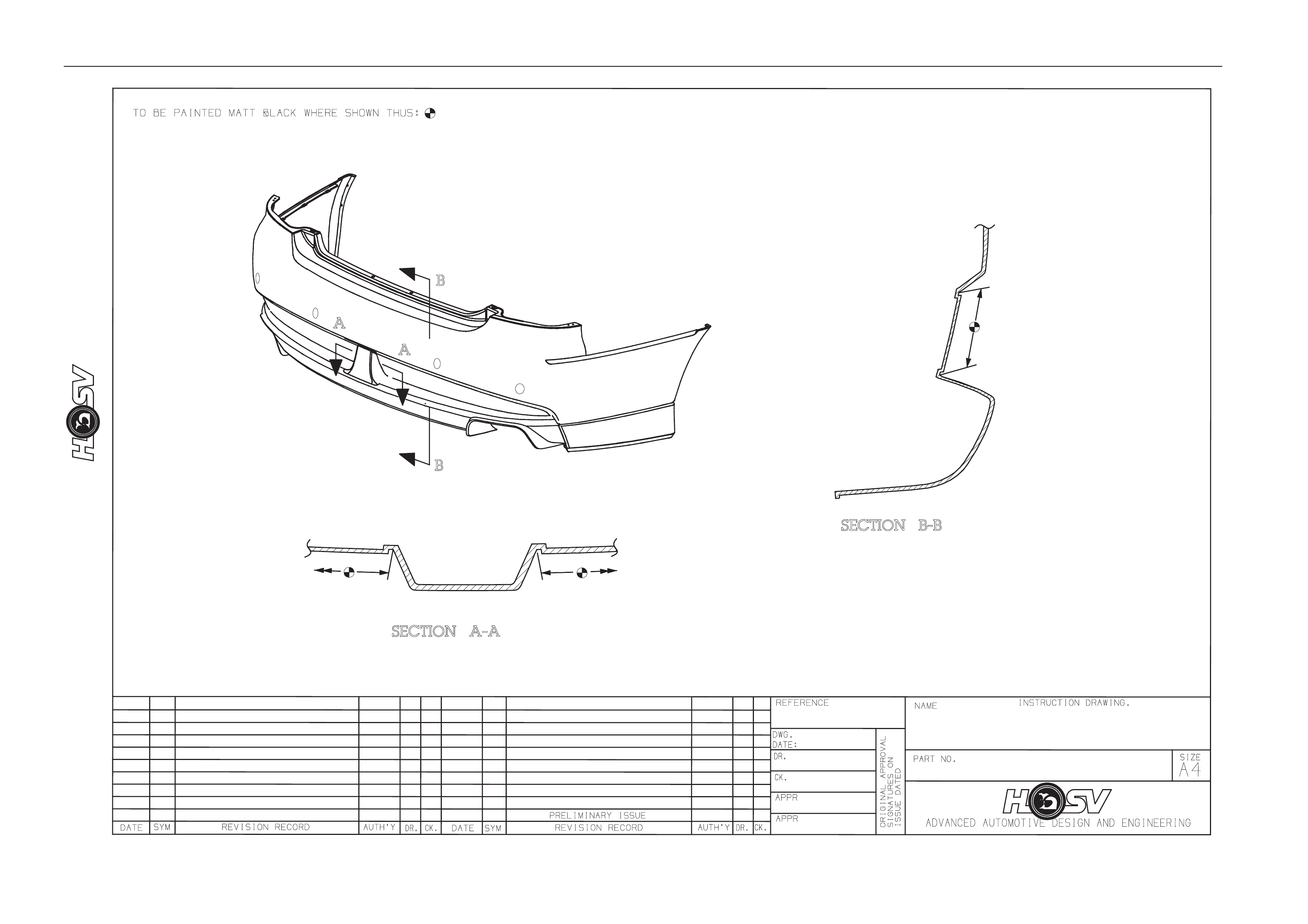
Body Page B-20
PAINT / REAR FACIA
VZ COUPE
AP
DP
DP
14/04/05
14I-050001
Body Page B-21
ADVANCED AUTOMOTIVE DESIGN AND ENGINEERING
DATE SYM REVISION RECORD
RELEASE
ADVANCED AUTOMOTIVE DESIGN AND ENGINEERING
DATE:
DR.
AUTH'Y
APPR
CK.
APPR
CK.
DR.
REFERENCE :
MODEL :
DWG.
ORIGINAL APPROVAL
ISSUE DATED
SIGNATURES ON
PARTNO.
1A2F040048
NAME INSTRUCTION DRAWING.
BODY EXTERIOR ORNAMENTATION
A4
SIZE
DP
AP
19.10.04
VZ COUPE
-
-
GTO - COUPE SKIRTBADGES
Body Page B-22
DATE SYM REVISION RECORD
REVISION RECORD
RELEASE
ADVANCED AUTOMOTIVE DESIGN AND ENGINEERINGADVANCED AUTOMOTIVE DESIGN AND ENGINEERING
DATE:
DR.
AUTH'Y
APPR
CK.
APPR
CK.
DR.
REFERENCE :
REFERENCE :
MODEL :
DWG.
ORIGINAL APPROVALORIGINAL APPROVAL
ISSUE DATEDISSUE DATED
SIGNATURES ONSIGNATURES ON
PART NO.
1A2F040049
NAME INSTRUCTION DRAWING.
INSTRUCTION DRAWING.
BODY EXTERIOR ORNAMENTATIONBODY EXTERIOR ORNAMENTATION
A4
SIZE
DP
AP
19/10/04
VZ COUPEVZ COUPE
-
-
VZ COUPEVZ COUPE
VIEW
A
A
50mm
10mm
55mm
15mm
Body Page B-23
13I-030004 1
GRILLE BADGE LOCATION
GTO - COUPE2&3
13C - 031101
GRILLE BADGE - GTO
50,0
35,0
SECA-A
A
A
75E - 030001
CLIP (2 PLACES)
13C - 031102
RETAINER
BADGE

Body Page B-24
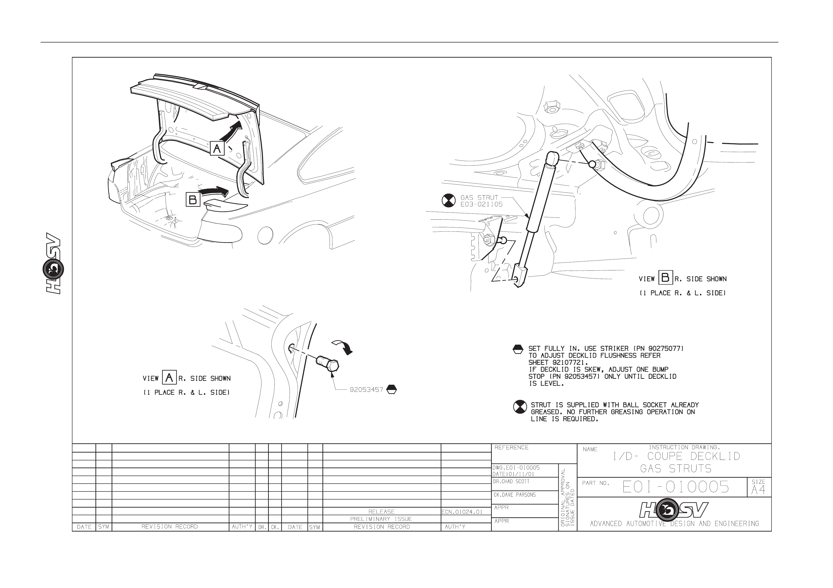
6 Rear Spoiler
ATTENTION
Before performing any service operation or other procedure described in this section refer to Section 00
CAUTIONS AND NOTES for correct workshop practices with regard to safety and/or property damage.
6.1 Service Operations
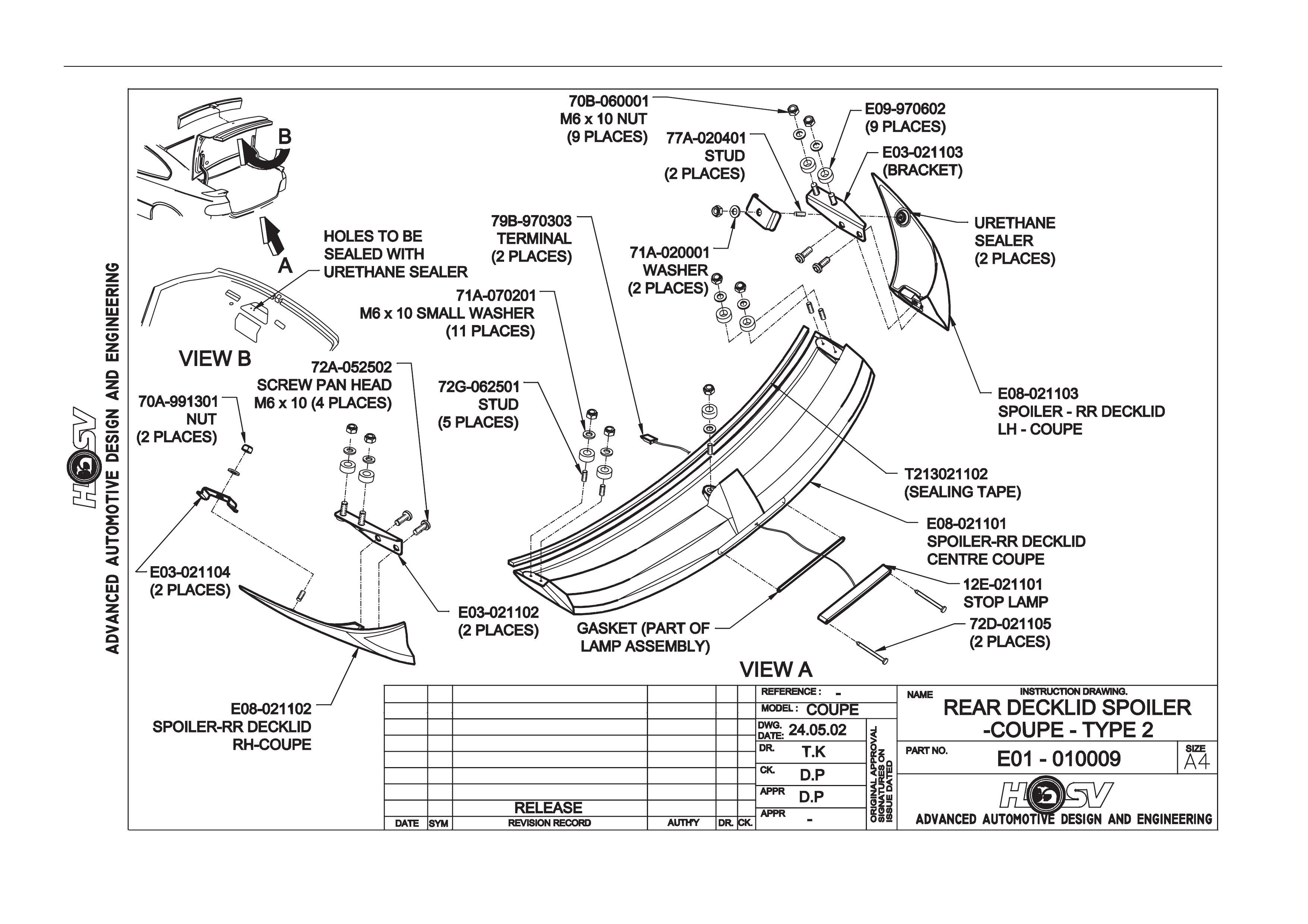
Refer drawing E0I-010009
Spoiler Ends
Removal
1. Apply masking tape to the Rear Quarter Outer Panel. T ape is to be located hard up against the edges of the spoil er
and to extend a width of at least 100mm around the s poiler ends;
2. Open the trunk lid;
3. Peal back to side trunk lid Rear Quarter Inner Trim to gain access to the spoiler ends front attachments;
4. Remove the attaching nut and bracket;
5. Remove the two rear upper spoiler end attaching bolts and two brack ets to spoiler attaching screws and flat
washers;
6. Carefully remove the spoiler and end from bod y work;
Installation
The installation for the spoiler ends is the rev ers of the remo val procedure.
Spoiler Centre Section
Removal
1. Remove the deck lid inner trim;
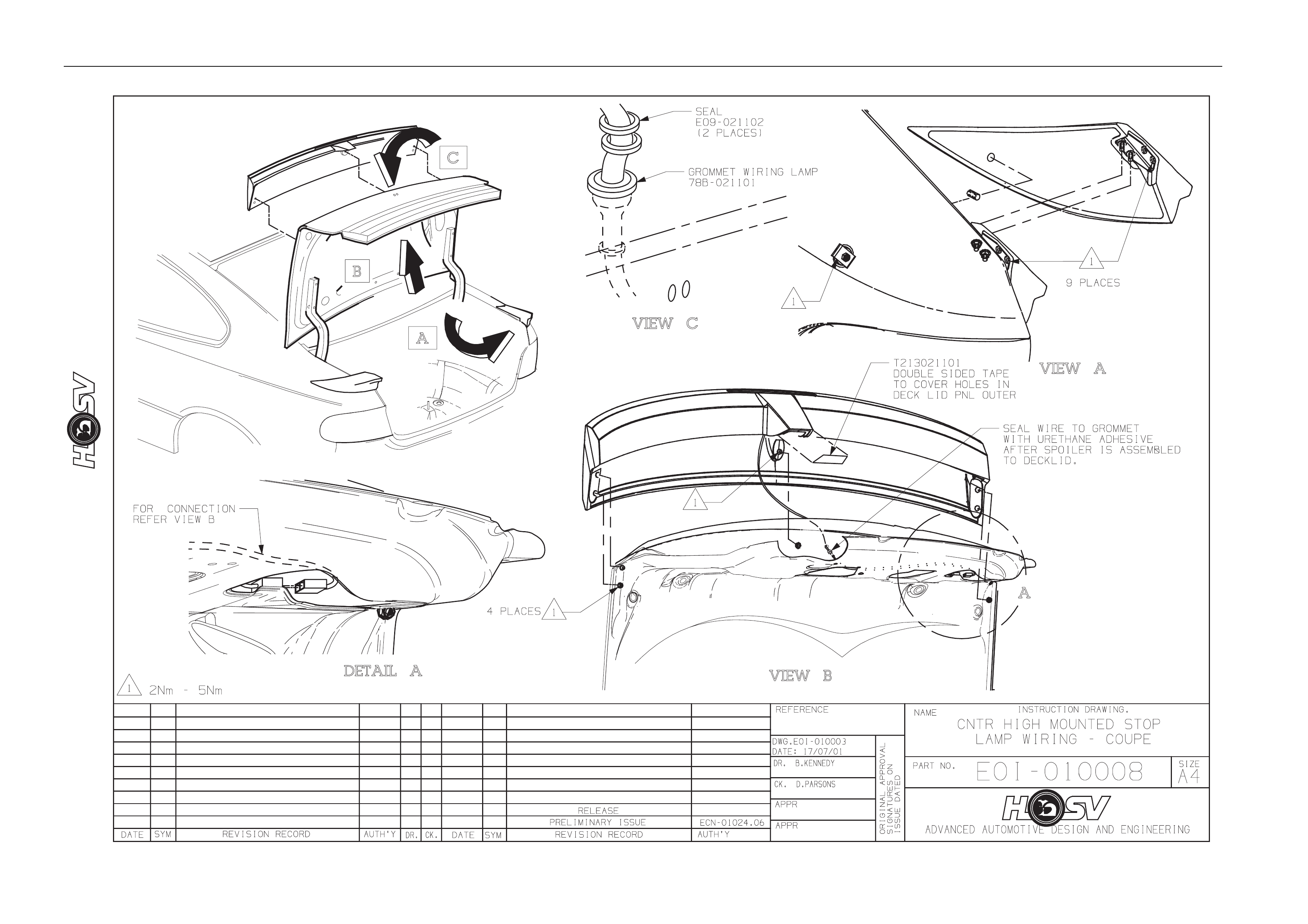
2. Refer to E0I-010008 for the removal of the centre high mounted stop lamp;
3. Remove the spoiler centre mounting flanged nut and stud;
4. Remove the four outer attaching nuts and washers (2 per side);
5. Remove the mounting studs from one side of the spoiler;
6. Carefully lift the spoiler centre from the deck lid.
Installation
The installation is the revers of the removal procedure. Do not attempt to install the centre spoiler with the studs installed
in the spoiler.
Body Page B-25
Body Page B-26
Body Page B-27
Body Page B-28
6.2 HSV Coupe Rear Spoiler – New Rear
Quarter Panel and New Spoiler
These instructions explain how to achieve the correct attaching hole locations for the rear spoilers when new panels are
being used and the spoilers are damaged beyo nd using as templates as pr eviously noted.
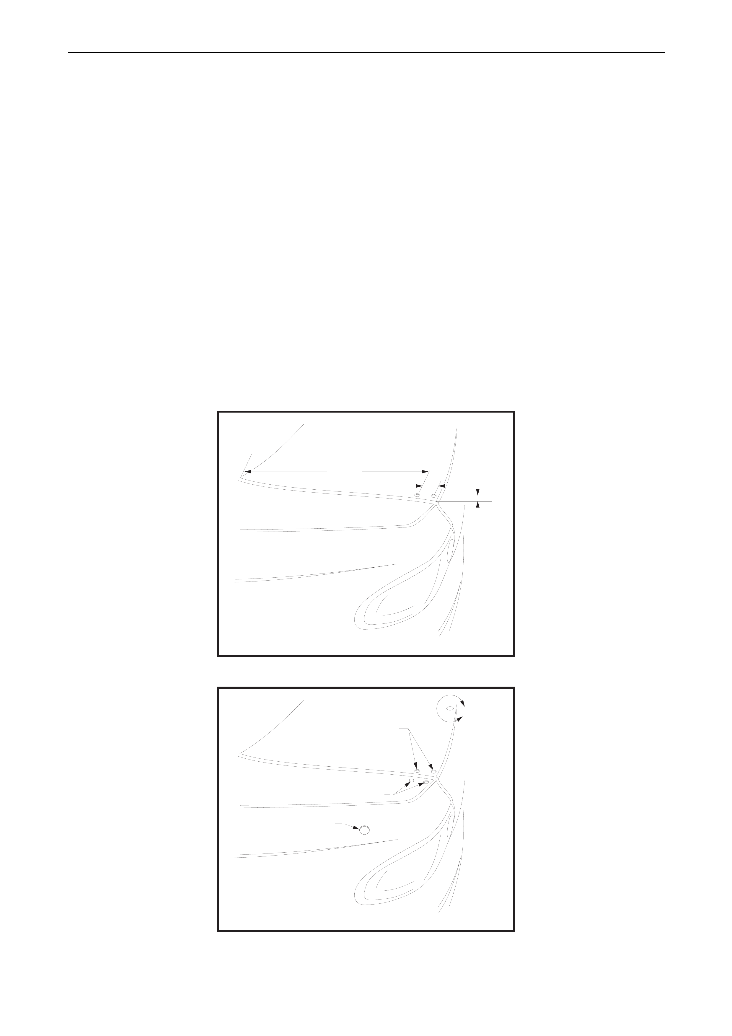
Decklid Centre Spoiler Outer Holes
Apply a 50 mm wide strip of masking tape along the outer edge of the Deck lid, both sides. The tape is to extend from the
front edge along the entire top surface.
Using a suitable pen or marker measure 18,0 mm in from the edge of the decklid and mark a line along the length of the
tape parallel to the edge.
From the front edge of the Decklid measure alo ng the line 462 mm to mark the front hole position.
Measure 20 mm in from the Decklid edge and mark a parallel lin e alo ng the last 100 mm of the Decklid top surface.
Intersect this line with a line 43 mm behind the front hole for the position of the rear hole. Refer to figure 1.
Centre punch the hole positions and carefully drill 6 mm pilot holes.
Using a step drill, open thes e holes up to 10,5 mm diameter (a 10 mm step drill produces a 10,5 diameter hole). Refer to
figure 2.
HOLE LOCATIONS IN
DECK LID OUTER PANEL
FIG 1
482.0 mm
43.0 mm
18.0 mm
DETAIL OF SPOILER
ATTACHING HOLE DIAMETERS
10.5 mm DIA. 2 HOLES
10.5 mm DIA. 2 HOLES
27.0 mm DIA. HOLE
REFER TO STEP 4 PROCEDURE
FIG 2
B
Body Page B-29
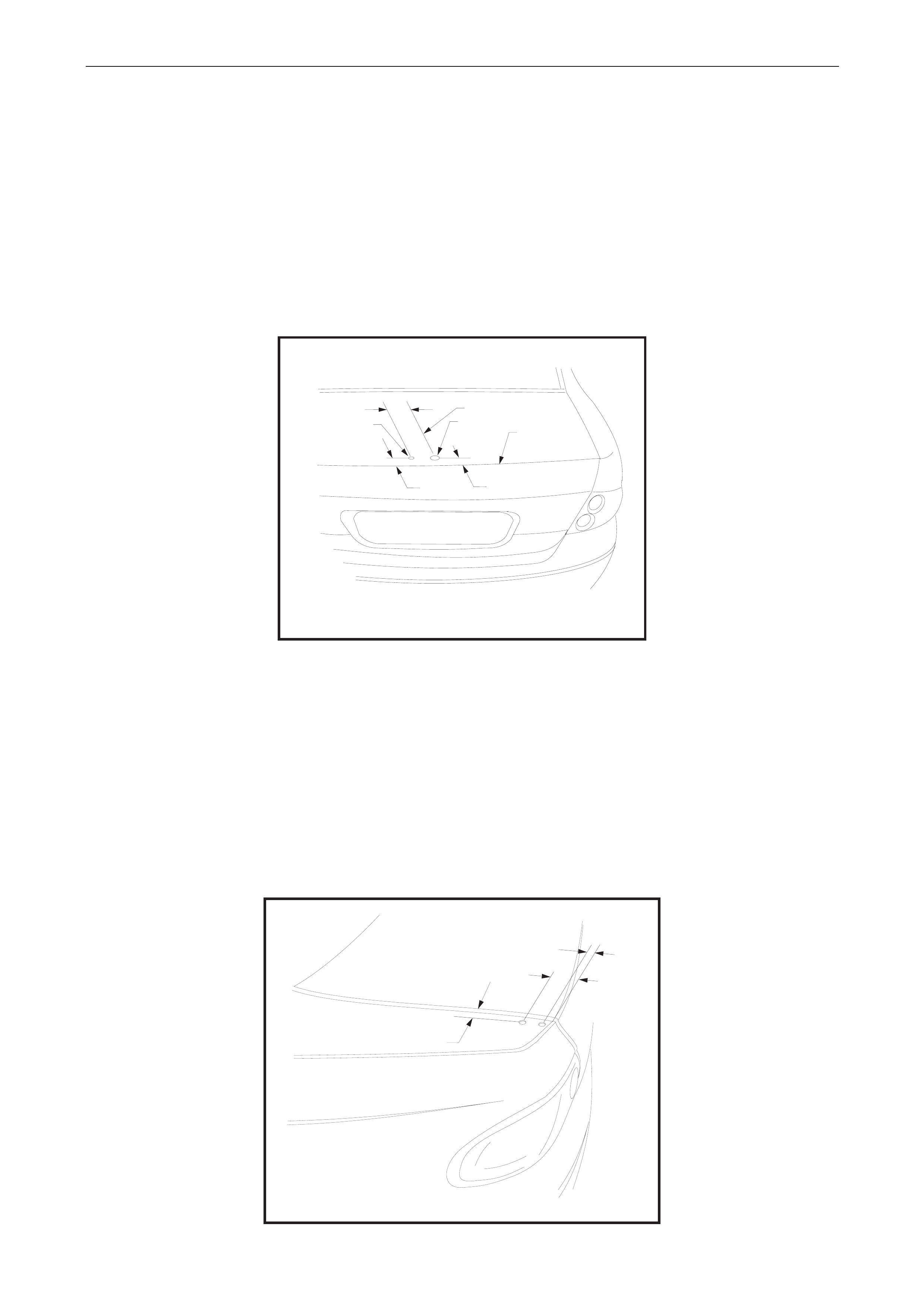
Centre Spoiler Centre Holes
Apply a 50 mm wide 100 mm long strip of masking tape in the approximate area for locatio n of the centre holes.
Working from the edges of the Decklid using a suitable pen mark the centreline of the Decklid.
From the rear edge of the Decklid measure forward 34 mm and mark the centre of the central attachi ng hole.
Draw a line parallel to and 50 mm to the right of the centerline. Intersect this line with a line 37 mm forward of the rear
edge of the Decklid for the attaching hole.
Carefully centre punch the hole positions and drill 6 mm pilot holes.
The Wiring hole is drilled to suit a 19 mm chassis punch. Refer to Figure 3
The centre attaching hole is drilled to 10,5 mm using a step drill. Refer to Figure 3
DETAIL OF SPOILER
CENTRAL ATTACHING HOLES
DECKLID REAR
UPPER EDGE
L DECKLID
C
FIG 3
37.0 mm
VIEW
B
50.0 mm
10.5 mm Dia Hole 20.0 mm Dia Hole
34.0 mm
Side Spoiler Upper Attaching Holes
Apply a 50 mm wide 100 mm long strip of masking tape in the approximate area for location of the holes.
Mark a line outboard of and p arallel to the edge of the Decklid open ing.
From the rear upper edge of the Rear Quarter Panel measure forward 31 mm and mark the rear hol e position.
From the rear upper edge of the Rear Quarter Panel measure forward 87 mm and mark the front hole positio n.
Carefully centre punch the hole positions and drill 6 mm pilot holes.
Using a step drill, open thes e holes up to 10,5 mm diameter. Refer to figure 4
HOLE LOCATIONS IN TOP
OF REAR QUARTER PANEL
87.0 mm
31.0 mm
10.5 mm
FIG 4
Body Page B-30
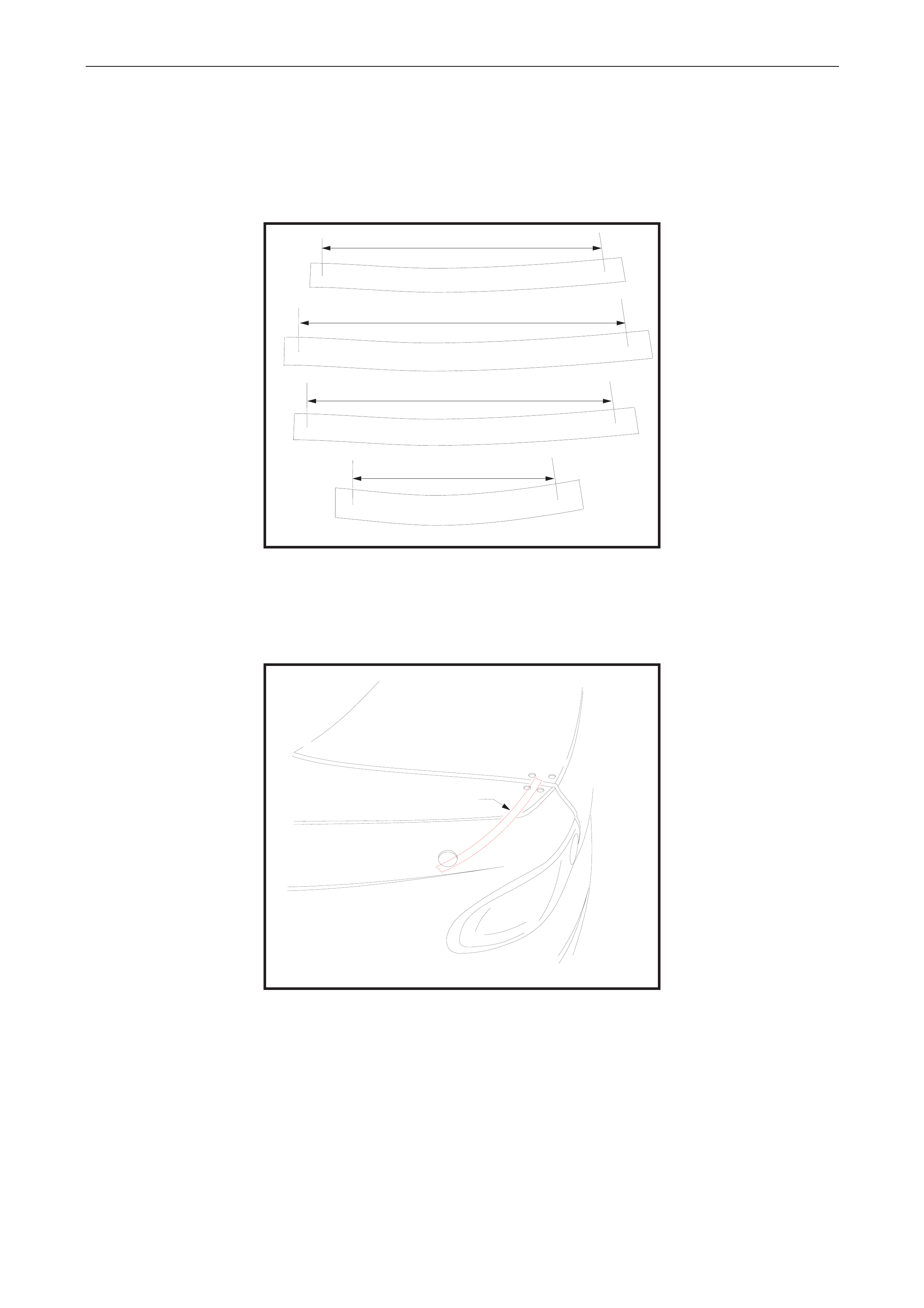
Side Spoiler Lower Attaching Hole
This hole is located measuring along the panel from 3 known points giving an intersection point for the hol e position.
Using 2 strips of masking tape stuck with adhesive side to side prepare 4 lengths to crea te measuring strips as sho wn
on Figure 9.
Mark these strips with the dimensions shown.
STRIP A
207,0 mm
207,0 mm
305,0 mm305,0 mm
STRIP BSTRIP B
297,0 mm297,0 mm
STRIP C
100,0 mm100,0 mm
STRIP D
FIG 9
Apply a 70 mm wide 100 mm long strip of masking tape in the approximate area for locatio n of the lower hole.
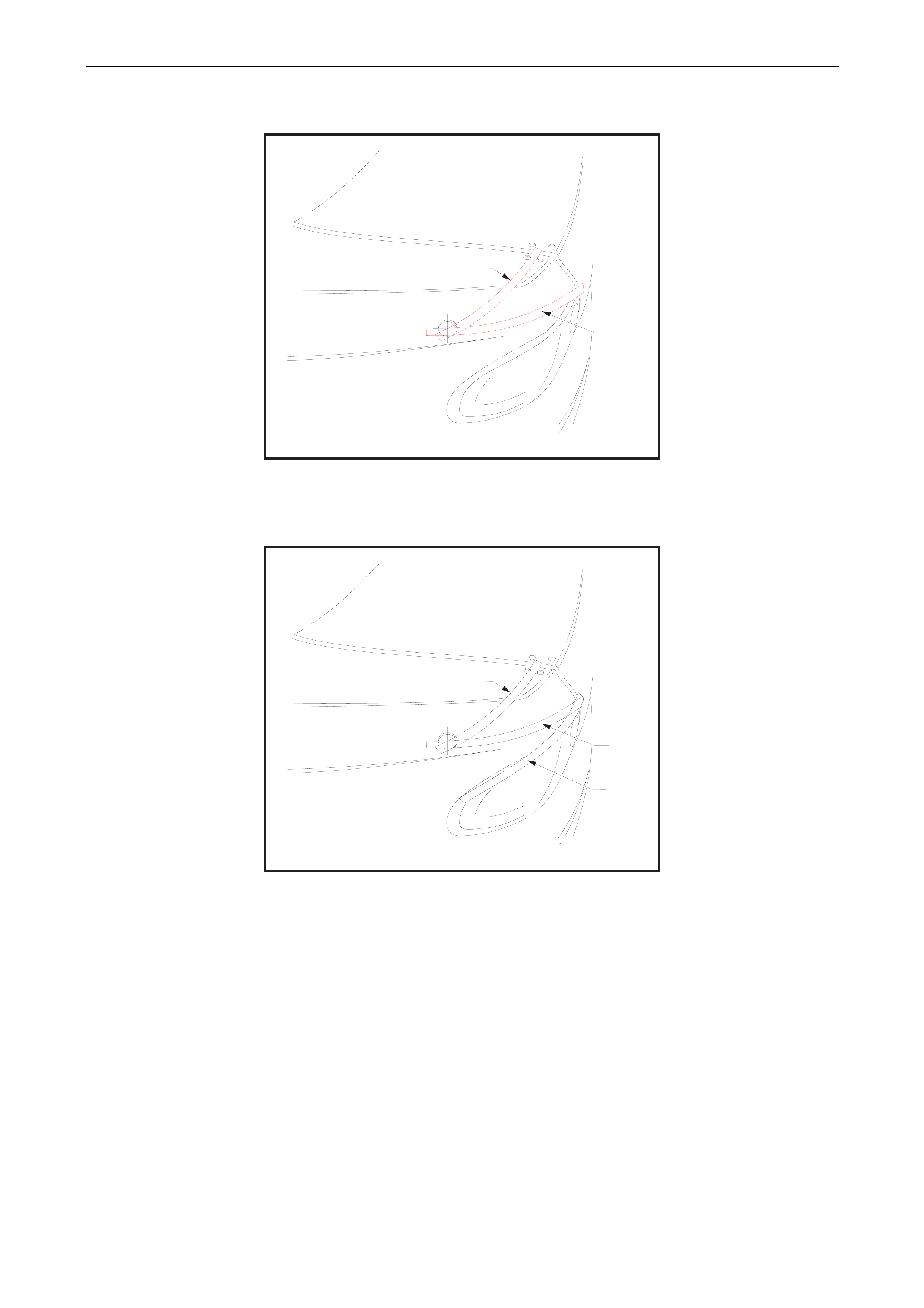
Using Strip A (207 mm distance) locate the datum mark in the centre of the front upper attaching hole and with the strip
running along the panel scribe an arc onto the tape. Refer Figure 5.
STEP 1
FOR LOCATION IN REAR
QUARTER OUTER PANEL
OF 27.0 mm DIA SPOILER HOLE FIG 5
STRIP A
Body Page B-31
Using Strip B (305 mm distance) locate the datum mark at the intersection of the top edg e of the Tail Lamp and the Rear
Quarter Panel, with the strip running along the panel scribe another arc onto the tape. Refer Figure 6.
STEP 2
FOR LOCATION IN REAR
QUARTER OUTER PANEL
OF 27.0 mm DIA SPOILER HOLE FIG 6
STRIP A
STRIP B
Using Strip C (297 mm distance) measure along the top edge of the Tail Lamp. Mark this position on a piece of tape
located at this position. Refer Figure 7.
STEP 3
FOR LOCATION IN REAR
QUARTER OUTER PANEL
OF 27.0 mm DIA SPOILER HOLE FIG 7
STRIP A
STRIP B
STRIP C
Body Page B-32
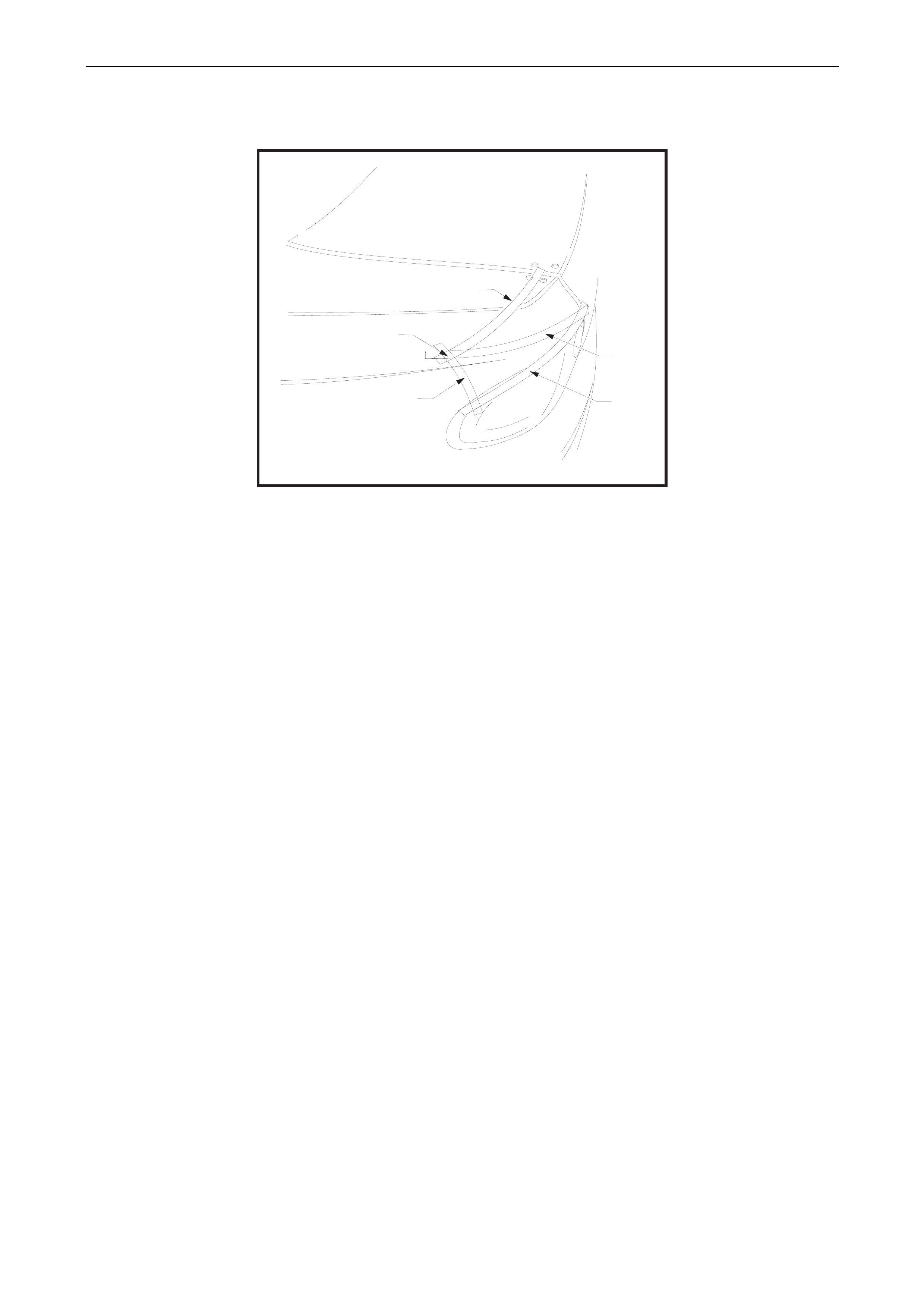
Using Strip D (100 mm distance) locate the datum mark at the point previ ously measured along the Tail Lamp upper
edge, with the strip running al ong the panel scribe a third arc onto the tape this is a confirmation of the previous arcs.
Refer Figure 8
STEP 4
FOR LOCATION IN REAR
QUARTER OUTER PANEL
OF 27.0 mm DIA SPOILER HOLE
FIG 8
STRIP A
CENTRE PUNCH AND DRILL
8.0 mm PILOT HOLE
STRIP B
STRIP C
STRIP C
Carefully centre punc h the hole position and drill 6 mm pilot hole.
Drill the pilot hole to suit the bolt on a 26,0 mm chassis punch.
Punch the hole to 26,0 mm.
De-burring and Anti-corrosion Treatment
All holes must be de-burred prior to anti-corrosion treatment.
All holes must be treated with Zink-Rich Prim er, allow primer to cure and then paint the holes car co lour automotive
touch up paint prior to final assembly.
Sealing
Once all spoiler components are in place ensure the seals cover the mounting holes.
General Precaution
Cover all components inside the rear com partment to protect against ingress of drilling swarf and dust.
All parts of the spoiler (center and sides) are to be temporarily attached to the vehicle in position with masking tape while
preliminary fitment check is completed.
Check the gaps and alignment of the 3 spoiler components at all assembly stages of this procedure.