
Options And Accessories Page J-1
Page J-1
Section J
Options And Accessories
ATTENTION
HSV vehicles are equipped with a Supplemental Restraint System (SRS). An SRS consists of seat belt pre-
tensioners (fitted to all front seats), a dri ver’s-side air bag , a passenger’s-sid e air bag and left and right hand
side air bags. Refer to CAUTIONS, Section 12M Occupant Protection System in the MY 2005 VZ Coupe Series
Service Information before performing any service operation on or around SRS components, the steering
mechanism or wiring. Failure to follow the CAUTIONS could result in personal injury or unnecessary SRS
system repairs.
1 Purpose...................................................................................................................................................2
2 HSV Sunroof ...........................................................................................................................................3
3 Fire Extinguisher....................................................................................................................................4
3.1 General Information............................................................................................................................................... 4
3.2 Service Operations................................................................................................................................................ 5
4 HSV High Intensity Discharge (HID) Xenon Lights.............................................................................7
4.1 General Information............................................................................................................................................... 7
4.2 Specific................................................................................................................................................................... 8
5 HSV Tyre Pressure Monitors...............................................................................................................12
5.1 Service And Warranty.......................................................................................................................................... 12
Troubleshooting................................................................................................................................................... 12
E1 Error............................................................................................................................................................ 12
E2 Error............................................................................................................................................................ 12
E3 & E4 Errors ................................................................................................................................................. 12

Options And Accessories Page J-2
Page J-2
1 Purpose
The purpose of this supplement is to provide information on the special options an d accessories fitted to the HSV VZ
Coupe. This information is design ed to supplement that contained in the Holden VZ Coupe. Service Manuals, and
details are given where differences occur between the HSV models and standard Holden models. A series of instruction
drawings detail the design cha nges and indicate specific part numbers, fitting instructions and relevant notes for vehicle
servicing.
NOTE
If specific technical data on a HSV model is not
contained in this supplement, obtain data for that
model from the relevant Holden Coupe VZ
Service Manual Supplement. References are
made throughout this section to Holden Service
Manuals, to assist in providing information for
specific service operations.
When hoisting (or jacking) HSV models,
ensure that the lifting h ead o f th e hoist lifts on
the chassis before the arm of the hoist
contacts the side-skirt


Options And Accessories Page J-4
Page J-4
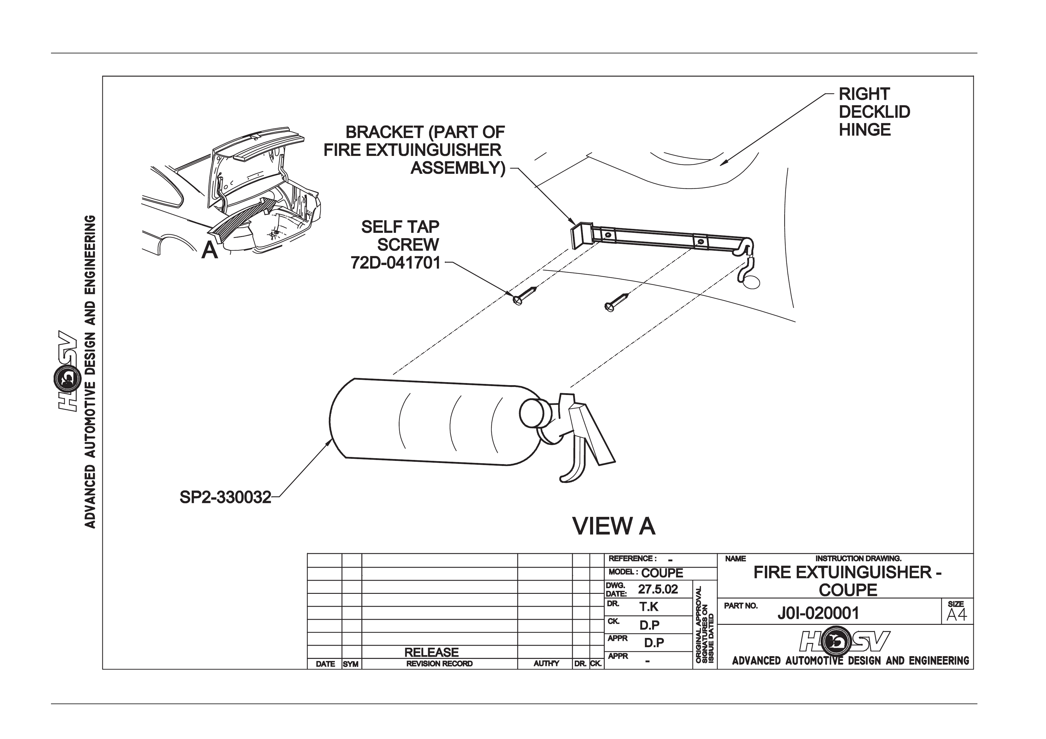
3 Fire Extinguisher
3.1 General Information
HSV VZ Coupe models are fitted with a HSV design fire extinguisher. The extinguisher is located in the rear lugga ge
compartment.

Options And Accessories Page J-5
Page J-5
3.2 Service Operations
The fire extinguisher should be subjected to a regular visual inspection in accordance with the instructions on the
extinguisher. Particularl y, the extinguisher should be inspected for damage and to ensure that the integral pressure
gauge registers the appropri ate internal pressure. When discharged or when the internal pressure is ou tside the
prescribed limits, the extinguishers should be serviced a nd re-charged by an appropriate supplier. New extinguishers
are available through the HSV spare parts systems.
Options And Accessories Page J-6
Page J-6

Options And Accessories Page J-7
Page J-7
4 HSV High Intensity Discharge
(HID) Xenon Lights
4.1 General Information
HSV VZ Coupe vehicles may be optioned with HID Driving Lights. These HID lights are located in the Fog lamp positi on
on the front fascia.
NOTE
HID Lights operate at quite high voltage levels, so
all care must be taken when removing front fascia
for service or repair. Please refer to
Service/Owners manual and take note of
warnings in engine bay.
HID lights are designed onl y to operate when high beam is activated. i.e. when indicator stalk is pulled toward (flashed)
or pushed back to operate hi gh beams. They are not a fog light and should not be used in any other ma nner, other than
described above.
HID Lights offer a brilliant white light that will illumi nate above and beyond a standard ‘Hi gh Beam’ system. All care must
be taken when using or adjusting these lights, as they can dazzle the operator.
The HID lights, ballasts and looms are not serviceable items and shoul d be replaced if damaged.

Options And Accessories Page J-8
Page J-8
4.2 Specific
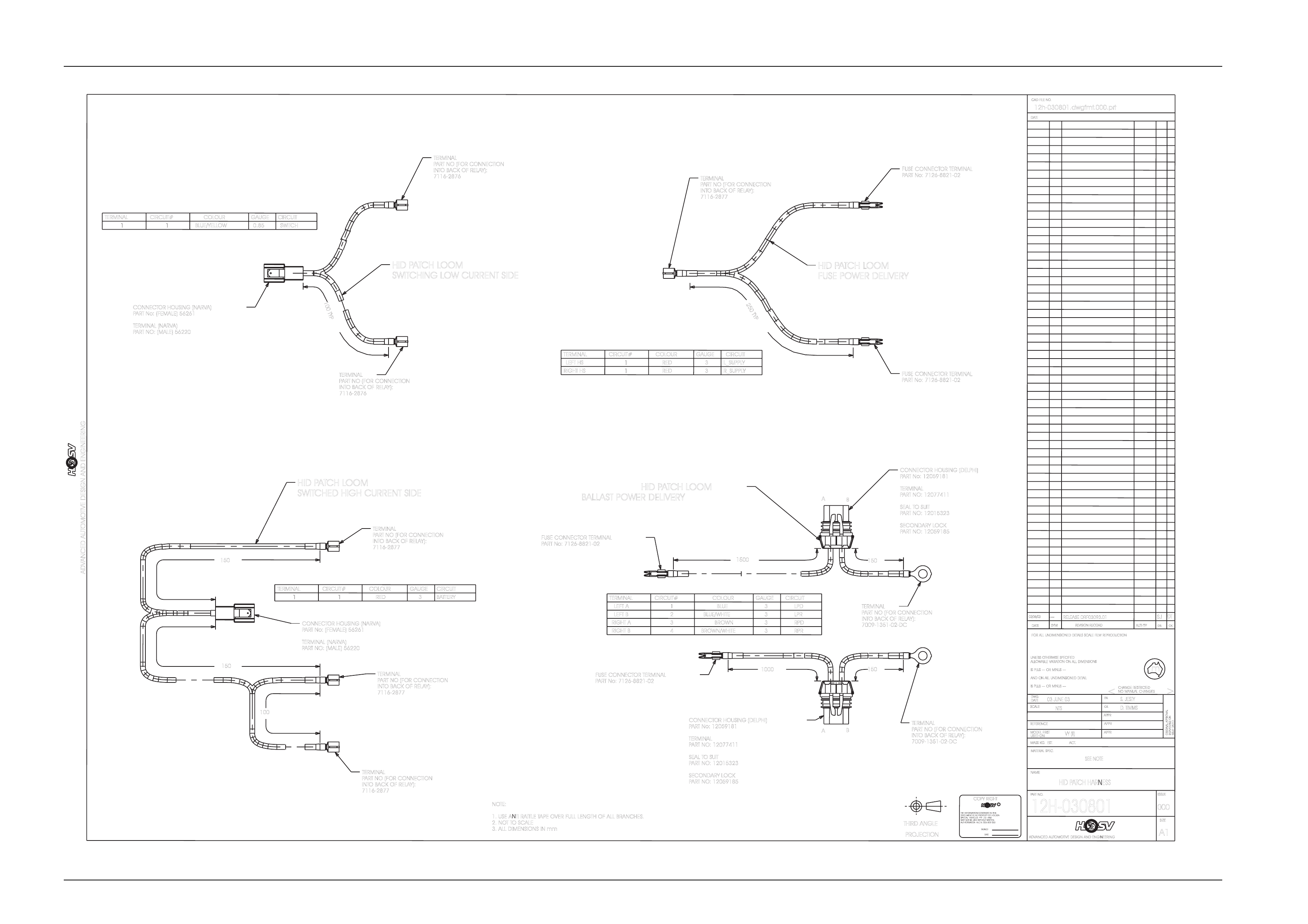
HID Lights use a separate patch harness that taps into the high beam activation circ uit, these looms also provide power
to the HID ballasts. The loom has dra wing number Clubsport: 12H-030801. Fuses for the HID lights are located next to
fuse box in engine bay and are labeled Left Hand LH HID and Right Hand RH HID.
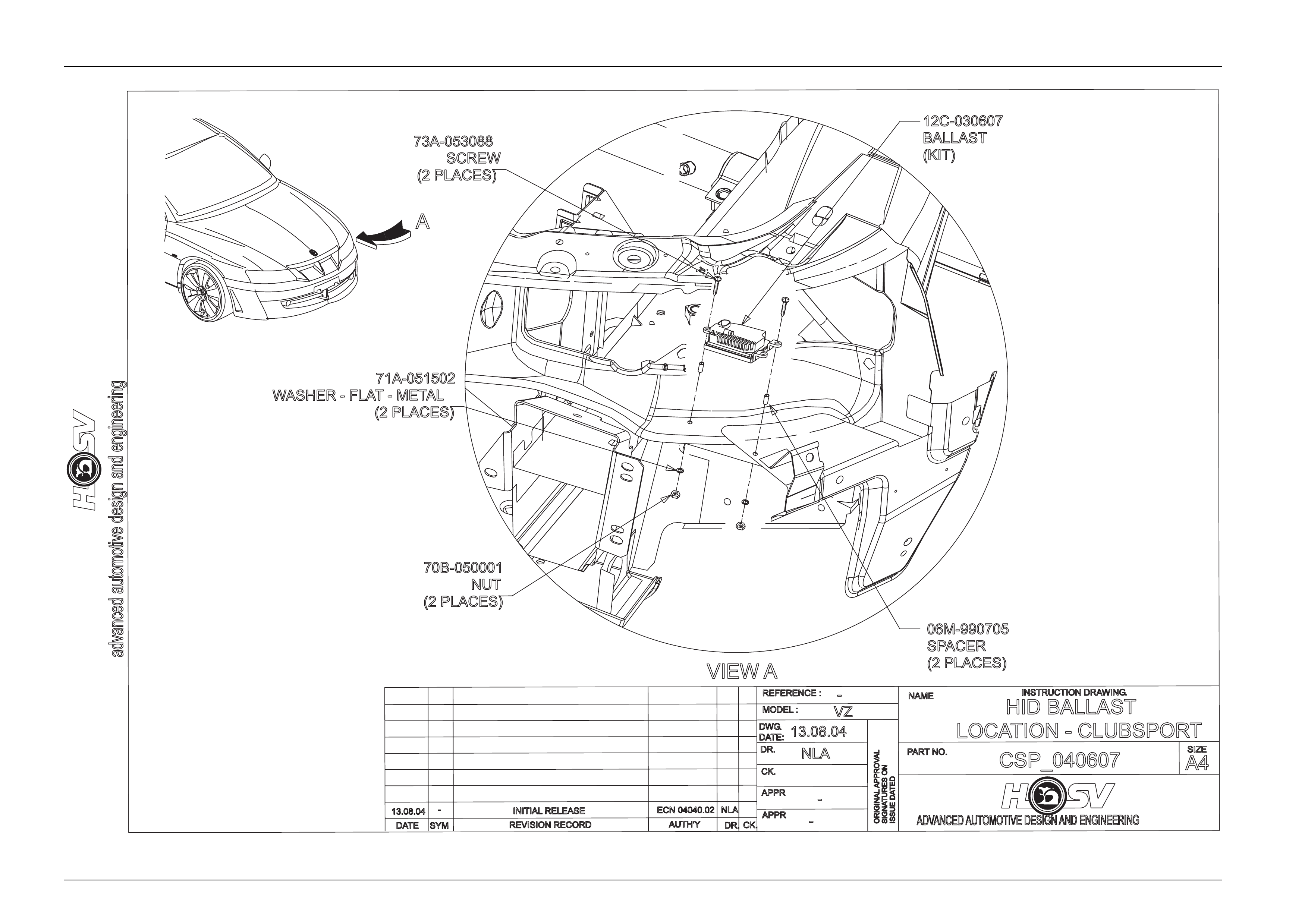
Ballasts are located under the headlights, attached to the sheet metal of vehicle, as per in struction drawing
Clubsport: CSP_040607. These ballasts power up the globes.
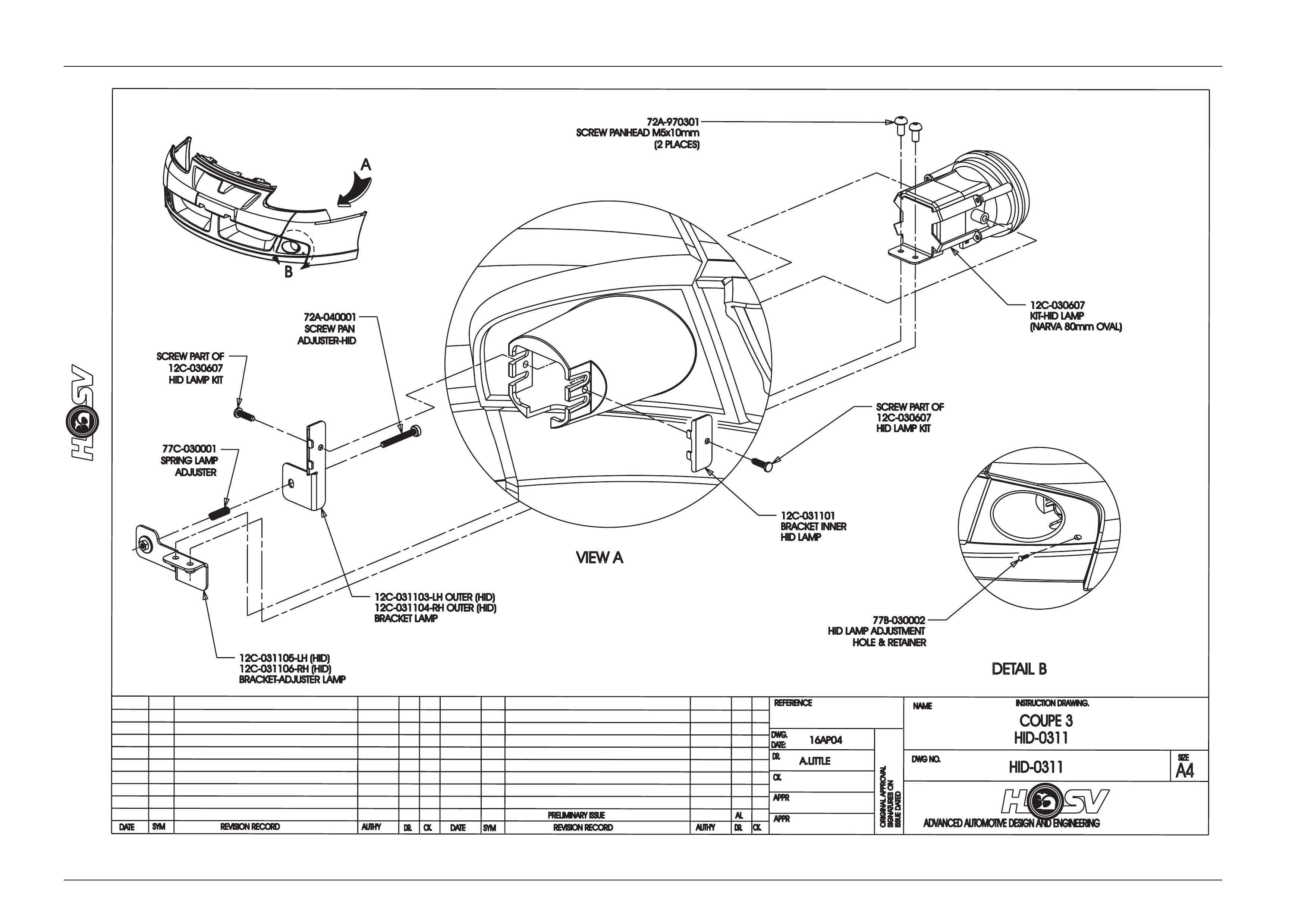
HID Globes are located in front fascia below headlights. They consist of a HID Bulb, Lens, Brackets and adjusting
equipment, all containe d within the Fog light position. Instruction dra wing number HID-0311
Options And Accessories Page J-9
Page J-9
RELEASED
RF03093.01
UNLESSO
THERWISES
PECIFIED
m
AUTH'TY
A1
APPR
>
AUTHORISATIONA.C.N.006802053
DWG.
THIRDA
NGLE
SYM
S. JESTY
NOMANUALC
HANGES
SPECIALVEHICLESPTYLTDAND
12h-030801.dwgfmt.000.prt
REFERENCE
SIGNATURESO
N
12H-030801
ANDO
NA
LLU
NDIMENSIONEDD
ETAIL
MATERIALS
PEC.
CK.
03 JUNE 03
SEE NOTE
THEINFORMATIONCONTAINEDINTHIS
FORA
LLU
NDIMENSIONEDD
ETAILSS
CALEF
ILMR
EPRODUCTION
DR.
DATE
ADVANCED AUTOMOTIVE DESIGN AND ENGINEERING
NAME
C
ADVANCED AUTOMOTIVE DESIGN AND ENGINEERING
APPR
SIZE
DATE
SIGNED
CK.
03/06/03
PARTN
O.
HID PATCH HARNESS
APPR
NTS
COPYR
IGHT
USEDO
N
<
MAYNOTBEUSEDWITHOUTWRITTEN
PROJECTION
SCALE
ISSUEDATED
D. TIMMS
DATE
ISSUE
IS PLUS-
--O
RM
INUS-
--
MASSK
G.E
ST.A
CT.
CHANGER
ESTRICTED
DOCUMENTISTHEPROPERTYOFHOLDEN
DR.
ALLOWABLEV
ARIATIONO
NA
LLD
IMENSIONS
MODELF
IRST
ORIGINALAPPROVAL
000
IS PLUS-
--O
RM
INUS-
--
REVISIONR
ECORD
CAD FILE NO.
DATE
--- SJ
NOTE:
1. USE ANTI RATTLE TAPE OVER FULL LENGTH OF ALL BRANCHES.
2. NOTT
OSCALE
3. ALL DIMENSIONS IN mm
VY(
II)
DT
CONNECTOR HOUSING (NARVA)
PART No: (FEMALE) 56261
TERMINAL (NARVA)
PART NO: (MALE) 56220
CIRCUIT
CIRCUIT#
TERMINAL GAUGE
COLOUR
3BATTERY
1RED
1
TERMINAL
PART NO (FOR CONNECTION
INTOBACK OF RELAY):
7116-2877
HID PATCH LOOM
SWITCHED HIGH CURRENT SIDE
CONNECTOR HOUSING (NARVA)
PART No: (FEMALE) 56261
TERMINAL (NARVA)
PART NO: (MALE) 56220
TERMINAL
PART NO (FOR CONNECTION
INTOBACK OF RELAY):
7116-2876
TERMINAL
PART NO (FOR CONNECTION
INTOBACK OF RELAY):
7116-2876
CIRCUIT#
TERMINAL
11
CIRCUIT
GAUGE
0.85 SWITCH
BLUE/YELLOW
COLOUR
HID PATCH LOOM
SWITCHING LOW CURRENT SIDE
100TYP
250TYP
CIRCUIT#
TERMINAL
LEFT HS 1
CIRCUIT
GAUGE
3L_SUPPLY
RED
COLOUR
RIGHT HS 1RED 3R_SUPPLY
FUSE CONNECTOR TERMINAL
PART No: 7126-8821-02
FUSE CONNECTOR TERMINAL
PART No: 7126-8821-02
1500 150
1000 150
TERMINAL
LEFT A
LEFT B
1
CIRCUIT
GAUGE
3LPD
BLUE
COLOUR
2BLUE/WHITE 3LPR
CIRCUIT#
RIGHT A3BROWN 3RPD
RIGHT B4BROWN/WHITE 3RPR
FUSE CONNECTOR TERMINAL
PART No: 7126-8821-02
FUSE CONNECTOR TERMINAL
PART No: 7126-8821-02
CONNECTOR HOUSING (DELPHI)
PART No: 12059181
TERMINAL
PART NO: 12077411
SEAL TOSUIT
PART NO: 12015323
SECONDARY LOCK
PART NO: 12059185
CONNECTOR HOUSING (DELPHI)
PART No: 12059181
TERMINAL
PART NO: 12077411
SEAL TOSUIT
PART NO: 12015323
SECONDARY LOCK
PART NO: 12059185
A
A
B
B
HID PATCH LOOM
FUSE POWER DELIVERY
HID PATCH LOOM
BALLAST POWER DELIVERY
TERMINAL
PART NO (FOR CONNECTION
INTOBACK OF RELAY):
7116-2877
TERMINAL
PART NO (FOR CONNECTION
INTOBACK OF RELAY):
7116-2877
150
150
100
TERMINAL
PART NO (FOR CONNECTION
INTOBACK OF RELAY):
7009-1351-02-DC
TERMINAL
PART NO (FOR CONNECTION
INTOBACK OF RELAY):
7116-2877
TERMINAL
PART NO (FOR CONNECTION
INTOBACK OF RELAY):
7009-1351-02-DC
Options And Accessories Page J-10
Page J-10
Options And Accessories Page J-11
Page J-11

Options And Accessories Page J-12
Page J-12
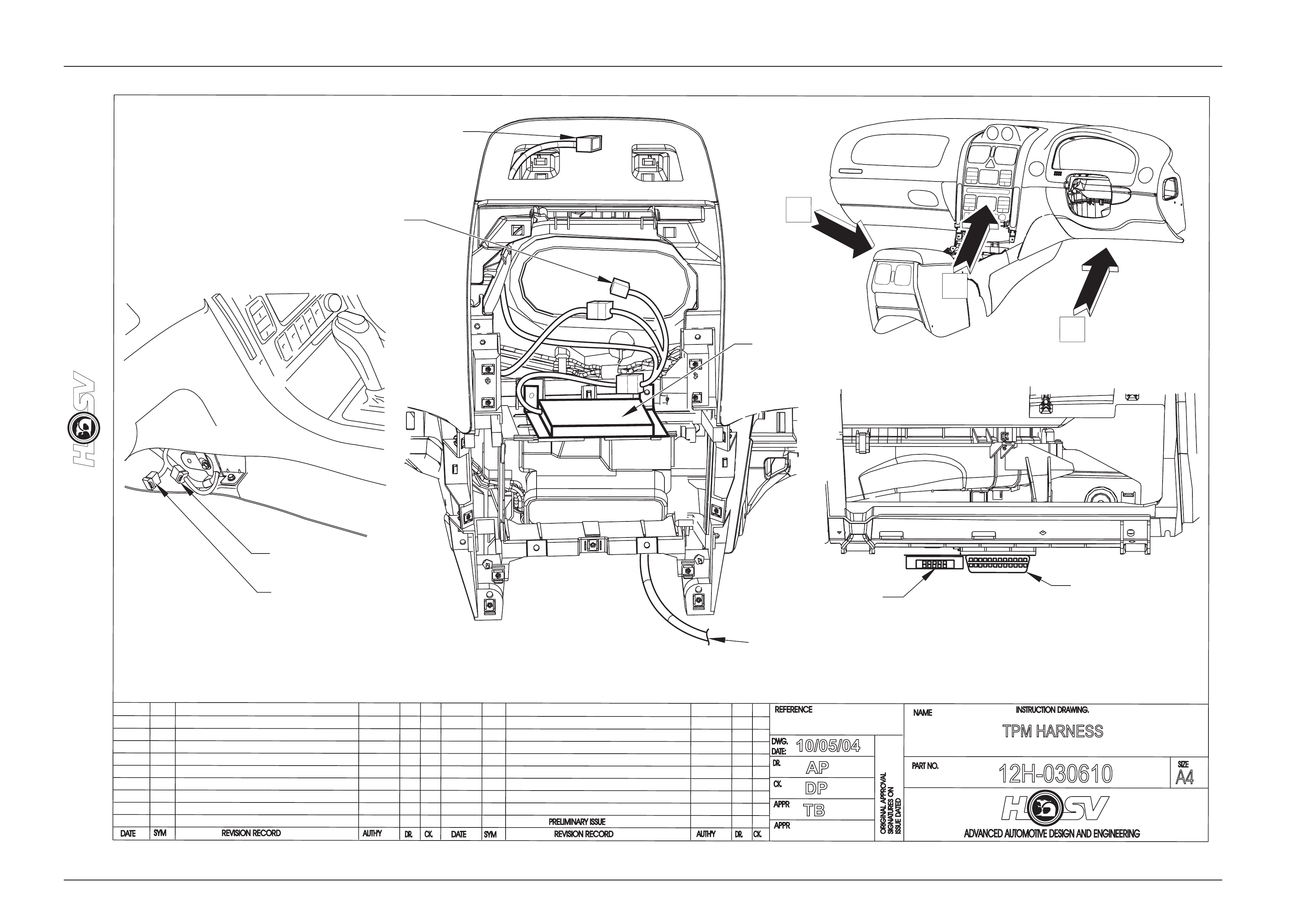
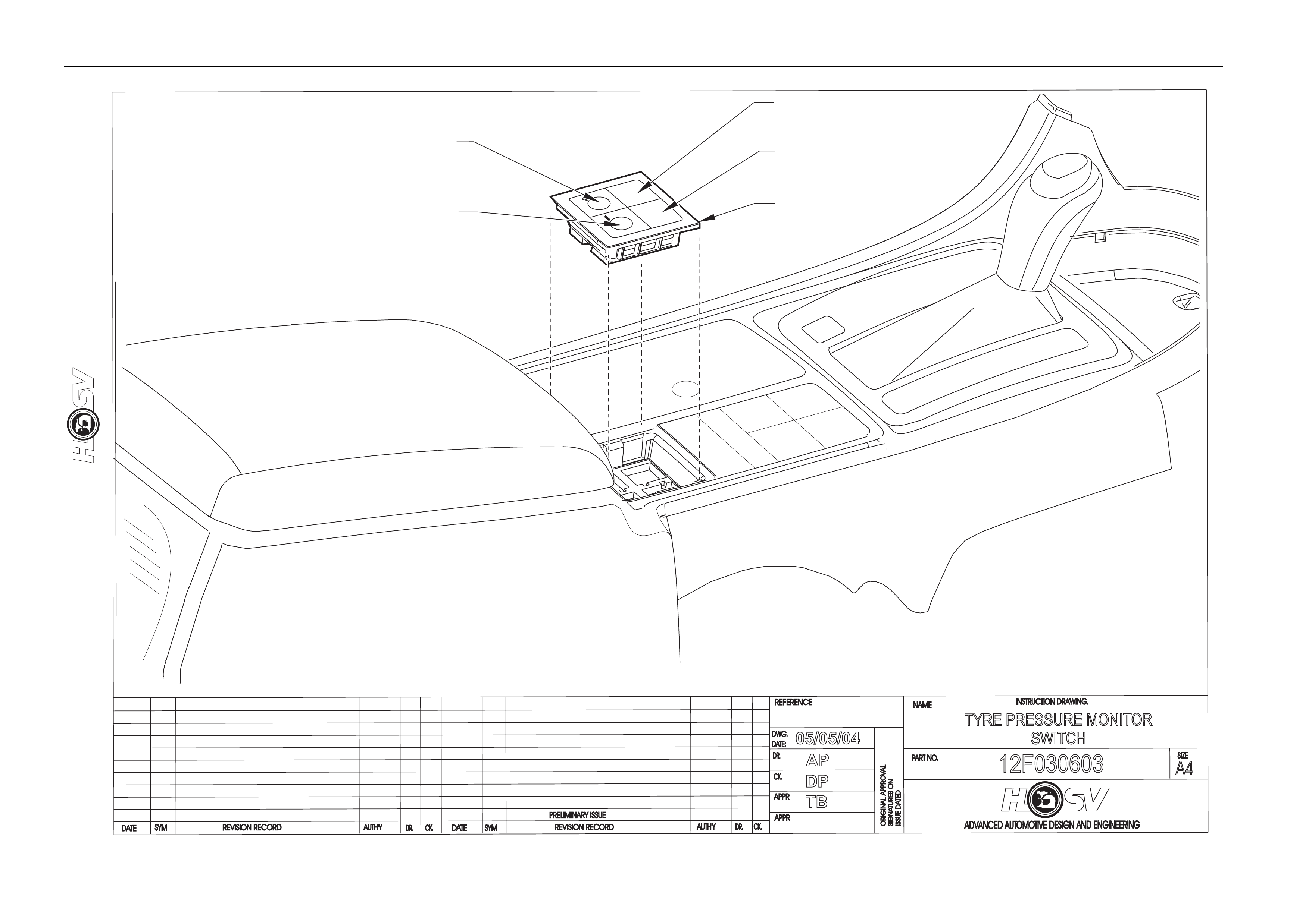
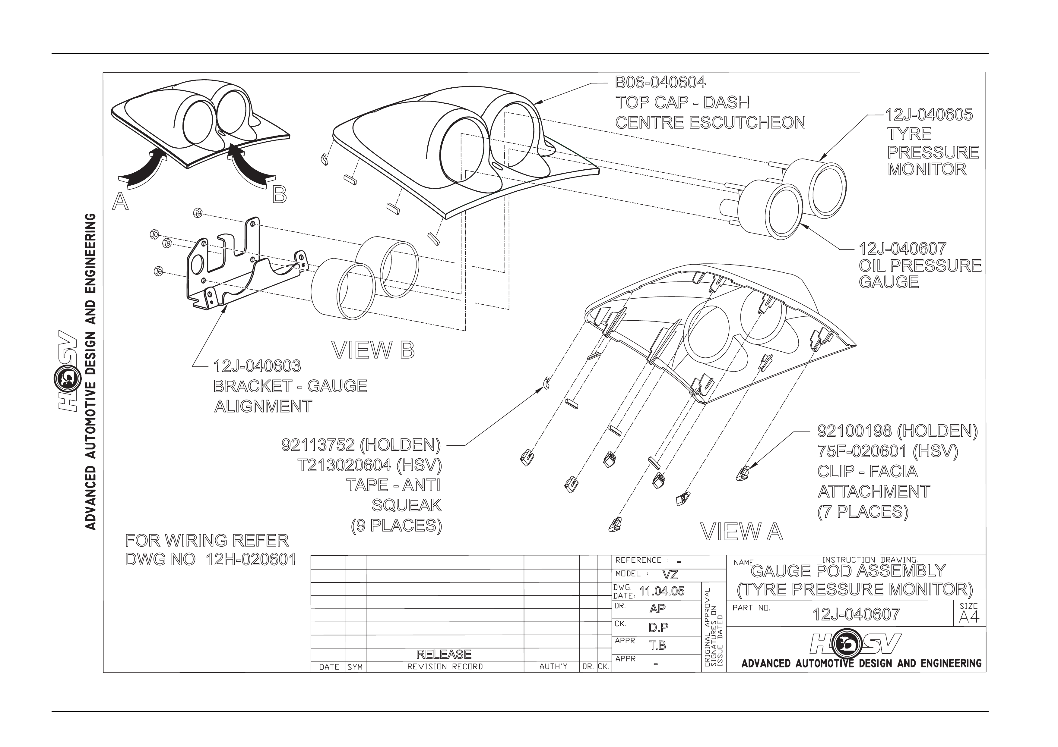
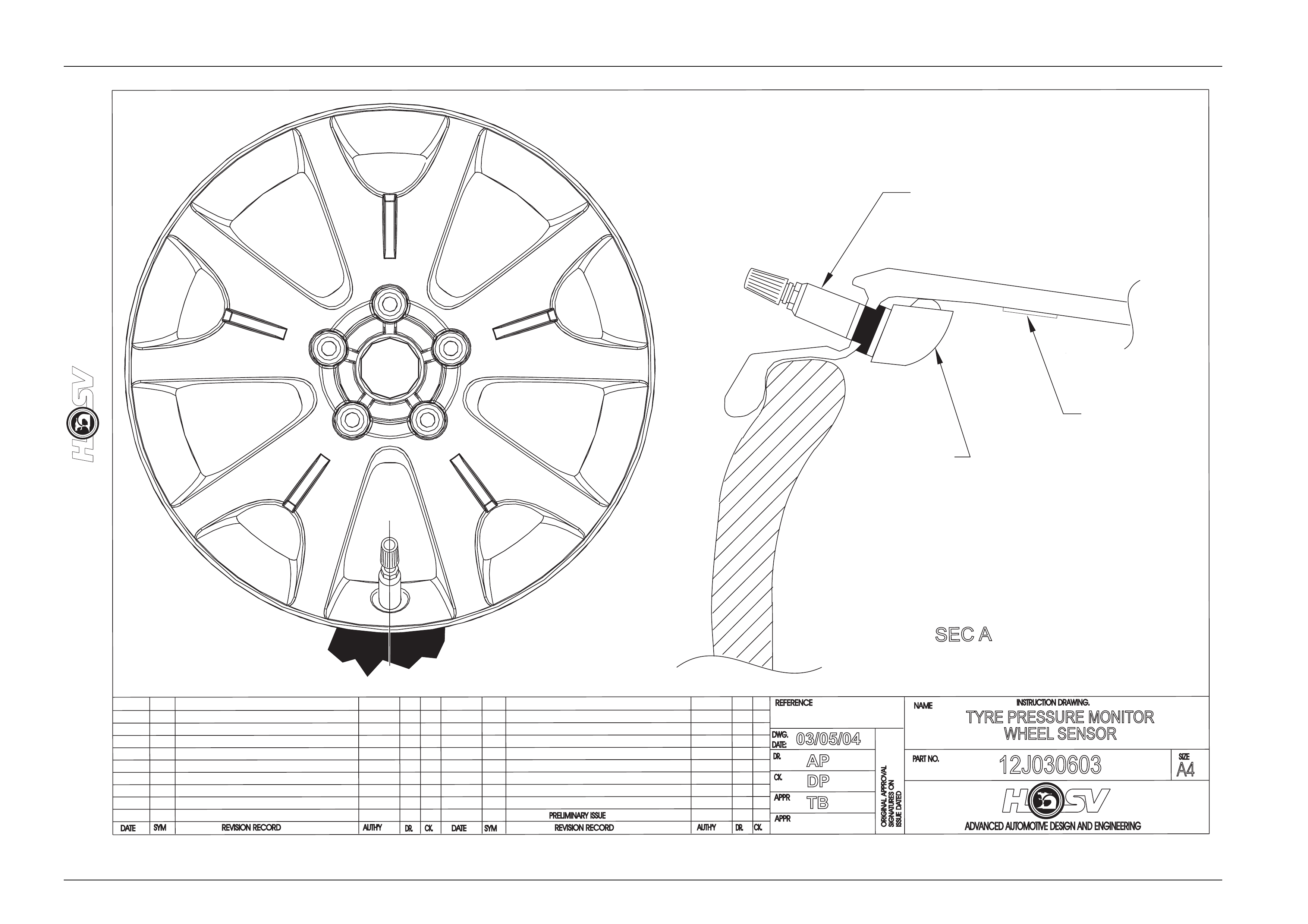
5 HSV Tyre Pressure Monitors
The HSV Tyre Pressure Monitor s ystem allows monitori ng of all tyre pressures from within the vehicles cabi n via an LED
readout. The system consists of a receiver u nit (mounte d to radio cradle in centre dash), a switch (mounted in centre
console), a readout (mounted in gaug e binicle), 4 sensors (one fitted inside each wheel) and a patch harness. For all
servicing and repair details refer to drawing numbers 12H-030610, 12F-030603, 12J-040607, 12J-030603 a nd the Tyre
Pressure Monitor Owners Handbook in vehicle glovebox. A trouble shooting guide is also provided at the end of this
section.
5.1 Service And Warranty
SYSTEM DIAGNOSIS
Error code on
display Component
failing Fault Action(s)
E1 Sensor(s)
Reciever Not transmitting RF
section malfunction If no transmission received within 5 minutes of driving,
refer to “Troubleshooting” before contacting dealer.
E2 Reciever and/or
Display EEPROM fault Refer to “Troubleshooting” before contacting dealer.
E3 Reciever and/or
Display Oscilator fault Refer to “Troubleshooting” before contacti ng dealer.
E4 Reciever and/or
Display Internal bus fault. Refer to “Troubleshooting” before contacting dealer.
Troubleshooting
E1 Error
This error may occur in certain vehicles where the receiver unit is powered even when the ignition is turned off. Cases
include vehicles where the cigarette lig hter outlet is powered without the vehicle running. Other possible causes may be
broken tyre sensors or a malfunctioning Receiver unit. Mismatches in tyre sensor ID may also cause thi s problem.
E2 Error
This error indicates that there is a problem with the data in the Receiver and/or Display units.
Causes of this error can include:
• Corrupted custom profile.
• Corrupted factory profile.
• The following may help identify the problem better.
• Power the unit on and off.
• If error has cleared ► operating with incorrect settings. Contact dealer
• If error persists ► Receiver (or Display) may have to be repl aced.
E3 & E4 Errors
These errors will usually represent an internal fault.
Try powering the unit on and off to clear these errors.
If these errors continuously occur the unit may have to be repl aced.
Options And Accessories Page J-13
Page J-13
DATE
ISSUE DATED
AUTH'Y
CK.
SYM
AUTH'Y
REVISION RECORD
DATE
SYM
SIGNATURES ON
ORIGINAL APPROVAL
DR.
ADVANCED AUTOMOTIVE DESIGN AND ENGINEERING
12H-030610
INSTRUCTION DRAWING.
A4
SIZE
TPM HARNESS
REVISION RECORD
PRELIMINARY ISSUE
CK.
NAME
PART NO.
CK.
REFERENCE
DWG.
DR.
DATE:
APPR
APPR
DR.
10/05/04
AP
DP
TB
A
B
C
VIEW CVIEW A
VIEW B
MOBILE PHONE
CONNECTOR
TPM HARNESS
12H-030610
TO TPM SWITCHES
AND MOBILE PHONE
CONNECTOR
TO TPM GAUGE
BINNACLE
TPM RECIEVER
12J-030605
TO
HAZZARD
WARNING
SWITCH
TECH 2
DIAGNOSTICS
CONNECTOR
TPM
DIAGNOSTICS
CONNECTOR
Options And Accessories Page J-14
Page J-14
DATE
ISSUEDA
TED
AUTH'Y
CK.
SYM
AUTH'Y
REVISION RECORD
DATE
SYM
SIGNATURES ON
ORIGINAL APPROVAL
DR.
ADVANCED AUTOMOTIVE DESIGN AND ENGINEERING
12F030603
INSTRUCTION DRAWING.
A4
SIZE
TYRE PRESSURE MONITOR
SWITCH
REVISION RECORD
PRELIMINARY ISSUE
CK.
NAME
PART NO.
CK.
REFERENCE
DWG.
DR.
DATE:
APPR
APPR
DR.
05/05/04
AP
DP
TB
SET
BEZEL
12F-030606
SET SWITCH
12F-030605
MODE SWITCH
12F-030603
TYRE SWITCH
12F-030603
COVER
12J-030606
Options And Accessories Page J-15
Page J-15
-
12J-040607
GAUGE POD ASSEMBLY
(TYRE PRESSURE MONITOR)
RELEASE -
AP
D.P
T.B
11.04.05
VZ
VIEW A
AB
VIEW B
12J-040607
OIL PRESSURE
GAUGE
12J-040605
TYRE
PRESSURE
MONITOR
B06-040604
TOP CAP - DASH
CENTRE ESCUTCHEON
12J-040603
BRACKET - GAUGE
ALIGNMENT
92113752 (HOLDEN)
T213020604 (HSV)
TAPE - ANTI
SQUEAK
(9 PLACES)
92100198 (HOLDEN)
75F-020601 (HSV)
CLIP -F
ACIA
ATTACHMENT
(7 PLACES)
FOR WIRING REFER
DWG NO 12H-020601
Options And Accessories Page J-16
Page J-16
DATE
ISSUE DATED
AUTH'Y
CK.
SYM
AUTH'Y
REVISION RECORD
DATE
SYM
SIGNATURES ON
ORIGINAL APPROVAL
DR.
ADVANCED AUTOMOTIVE DESIGN AND ENGINEERING
12J030603
INSTRUCTION DRAWING.
A4
SIZE
TYRE PRESSURE MONITOR
WHEEL SENSOR
REVISION RECORD
PRELIMINARY ISSUE
CK.
NAME
PART NO.
CK.
REFERENCE
DWG.
DR.
DATE:
APPR
APPR
DR.
03/05/04
AP
DP
TB
A
A
SECA
VALVE
10B-030608
SENSOR
12J-030604
LABEL
(BAR CODE)
00A-030614