
Suspension Page C-1
Page C-1
Section C
Suspension
ATTENTION
HSV vehicles are equipped with a Supplemental Restraint System (SRS). An SRS consists of seat belt pre-
tensioners (fitted to all front seats), a d river’s-side air bag, a passeng er’s-side air bag and left and right h and
side air bags. Refer to CAUTIONS, Section 12M Occupant Protection System in th e MY 2005 VZ Series Ser vice
Information before performing any service operation on or around SRS components, the steering mechanism
or wiring. Failure to follow the CAUTIONS could result in personal injury or unnecessary SRS system repairs.
1 Purpose...................................................................................................................................................2
2 Front Suspension...................................................................................................................................3
2.1 General Information............................................................................................................................................... 3
2.2 Service Intervals .................................................................................................................................................... 4
2.3 Service Operations................................................................................................................................................ 5
2.4 Front Suspension Components............................................................................................................................ 6
Front Strut Detail.................................................................................................................................................... 6
Front Spring Detail................................................................................................................................................. 6
Front Stabiliser Bar Detail..................................................................................................................................... 7
3 Rear Suspension....................................................................................................................................8
3.1 General Information............................................................................................................................................... 8
3.2 Service Operations................................................................................................................................................ 9
3.3 Rear Suspension Components........................................................................................................................... 10
Rear Spring Detail................................................................................................................................................ 10
Rear Shock Absorber Detail................................................................................................................................ 10
Rear Stabiliser Bar Detail.................................................................................................................................... 11
4 Suspension Ohlins Supplement.........................................................................................................12
4.1 General Information............................................................................................................................................. 12
4.2 Servicing/Inspection and Maintenance.............................................................................................................. 13
Inspection Points................................................................................................................................................. 13
5 Rear Final Drive and Drive Shafts.......................................................................................................17
5.1 General Information............................................................................................................................................. 17
5.2 Major Service Operations.................................................................................................................................... 18
Final Drive Assembly Unit Repair....................................................................................................................... 18
Reassemble ..................................................................................................................................................... 18
5.3 Pinion Flange ....................................................................................................................................................... 24
Replace (Vehicles With a Rear Rubber Coupling)............................................................................................. 24
Using Old Oil Seal............................................................................................................................................ 24
6 Suspension Service Alignment Data..................................................................................................27
Rear Suspension Service Alignment Data......................................................................................................... 27
Front Suspension Service Alignment Data........................................................................................................ 27
Service Information ............................................................................................................................................. 28
7 Special Tools ........................................................................................................................................29
Suspension Page C-2
Page C-2
1 Purpose
The purpose of this section is to provide information on the front and rear suspension assemblies fitted to HSV VZ
models. The information is designed to supplement the information contained in the Holden VZ Service Manuals, and
details are given where differe nces occur between the HSV models and sta ndard Holden models. A series of instructio n
drawings describe the design changes and indicate specific part numbers, fitting instructions and relevant notes for
vehicle servicing.
NOTE:
If specific technical data on a HSV model is not
contained in this supplement, obtain data for that
model from the relevant Holden VZ series
Service Information Supplement. Refer ences are
made throughout this section to Holden Service
Manuals, to assist in providing information for
specific service operations.
When hoisting (or jacking) HSV models,
ensure that the lifting h ead o f th e hoist lifts on
the chassis before the arm of the hoist
contacts the side-skirt

Suspension Page C-3
Page C-3
2 Front Suspension
2.1 General Information
The front suspension assembly fitted to all HSV VZ models is based on the Holden ‘MacPherson Strut’ design. The
assembly consists of the front suspension crossmember cradle,lower control arms,stabilizer bar and heavy duty strut
assemblies. All HSV front suspension struts are gas pressurized. This basic assembly is then modified by HSV to
provide a suspension system more suited to the requirements of the HSV vehicle.

Suspension Page C-4
Page C-4
2.2 Service Intervals
HSV front suspension assemblies ar e to be serviced at the intervals directed in : Section 0B – Lubrication And Service of
the VZ Service Information.

Suspension Page C-5
Page C-5
2.3 Service Operations
Service front suspension assemblies fitted to HSV models in accordance with the relevant Holden VZ Series Service
Information. Additional service requirements for specific HSV suspension assemblies are detailed in suc c eeding
paragraphs.
SAFETY AND CAUTIONARY NOTE FOR
VEHICLES EQUIPED WITH ABS
Whenever any component that forms a part of the ABS is disturbed, it is vital that the complete ABS system is checked.
Refer to Section 5B ABS/TCS/ESP General Information of the Holden VZ Service Inform ation
Suspension Page C-6
Page C-6
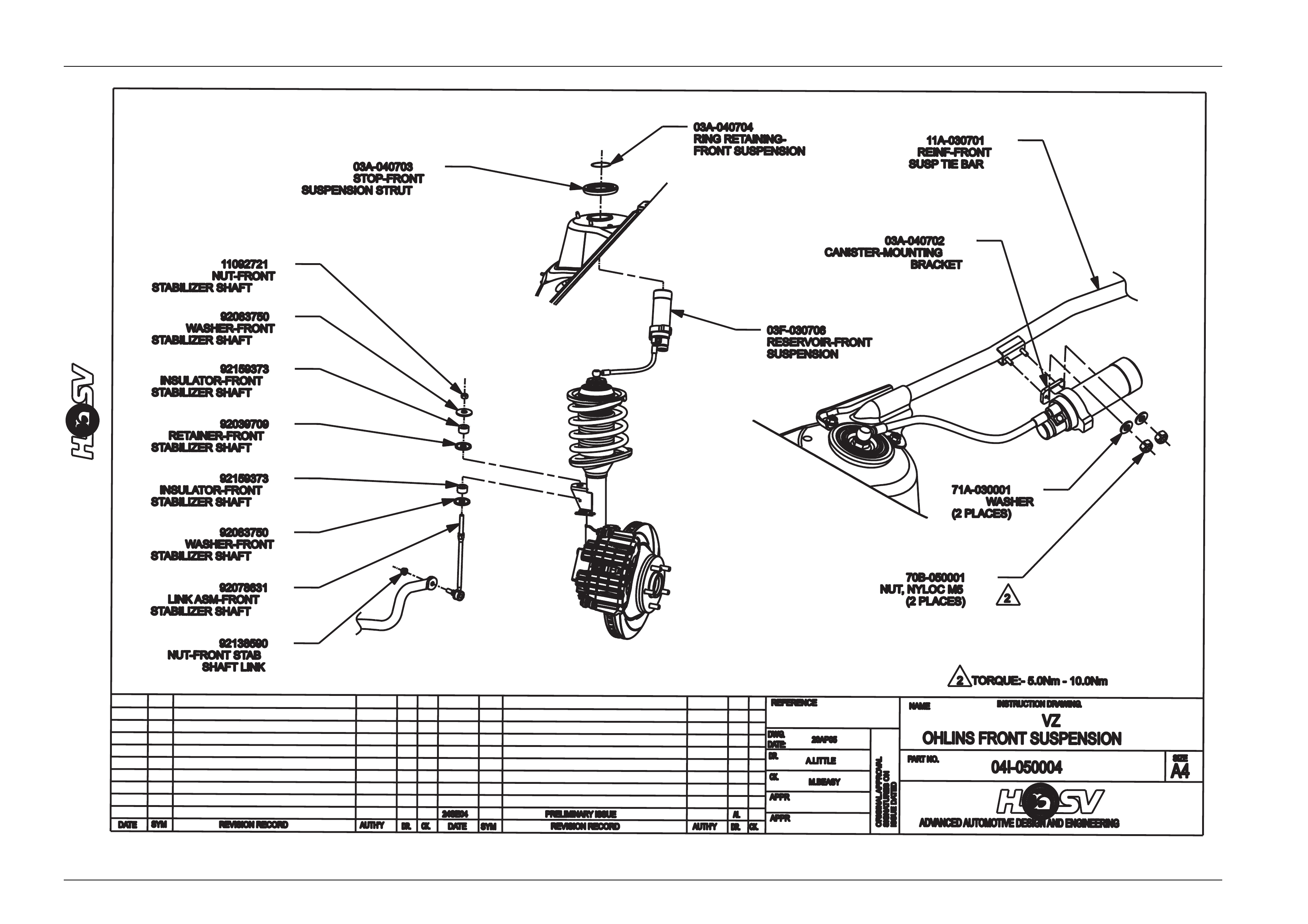
2.4 Front Suspension Components
The following components are fitted to front suspension assemblies as indicated:
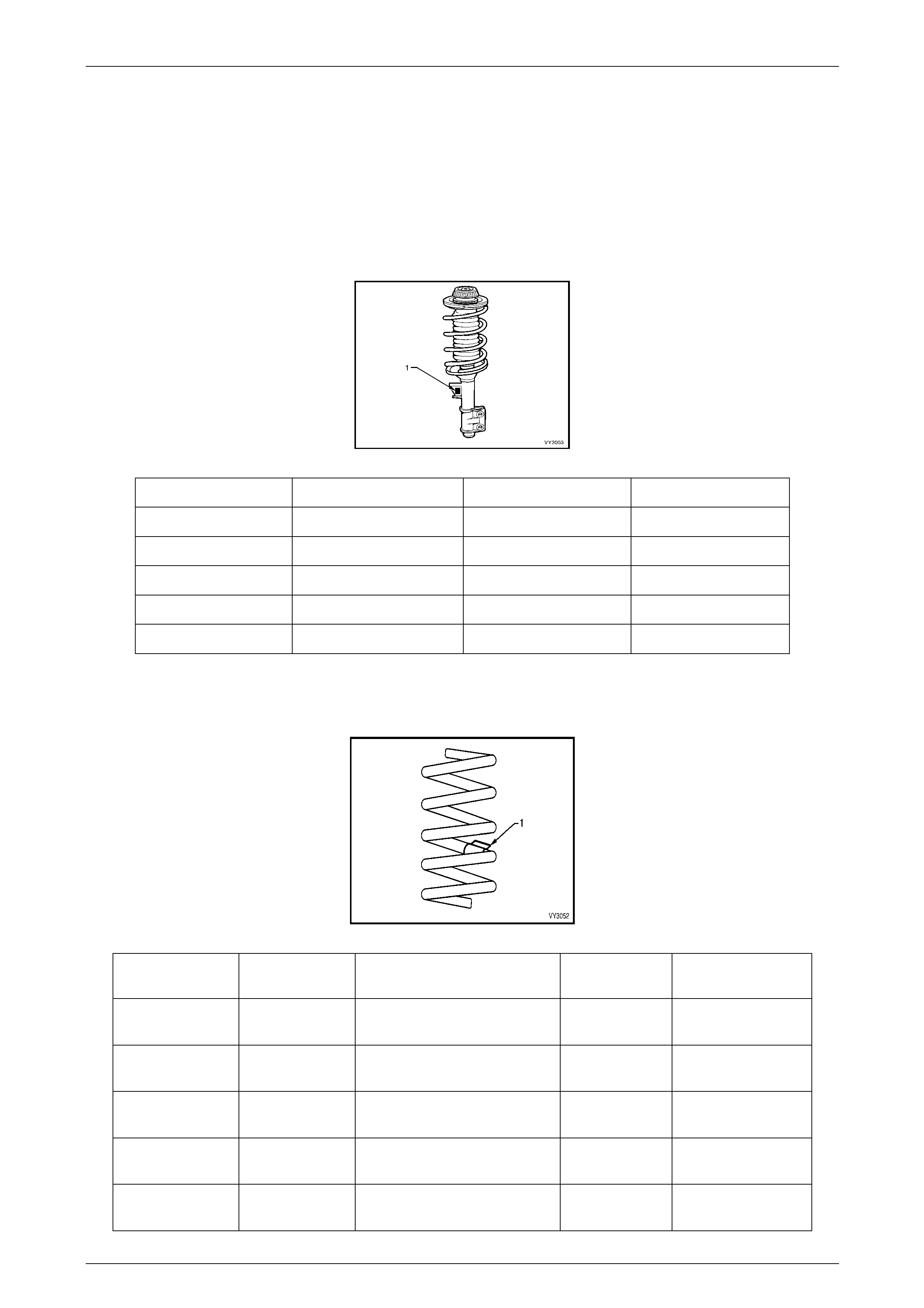
Front Strut Detail
Type..............................................................................Twin Tube Hydraulic, gas pressurized
Piston..............................................................................................................................30mm
Identification of the front strut assemblies fitted to a particul ar vehicle can be achieved by cross referencing either the
stamped in part number (see strut lower tube), or production identification tag (1) with the table below.
Model Part Number LH Strut Part Number RH Strut Production ID Code
Touring 03F - 030601 03F - 030602 TY2
Performance 03F - 030701 03F - 030702 PY2
Touring (Maloo) 03F - 030601 03F - 030602 TY2
Luxury 03F - 030601 03F - 030602 LY2
Ohlins 03F - 030705 03F - 030706 No ID Code “Ohlins”
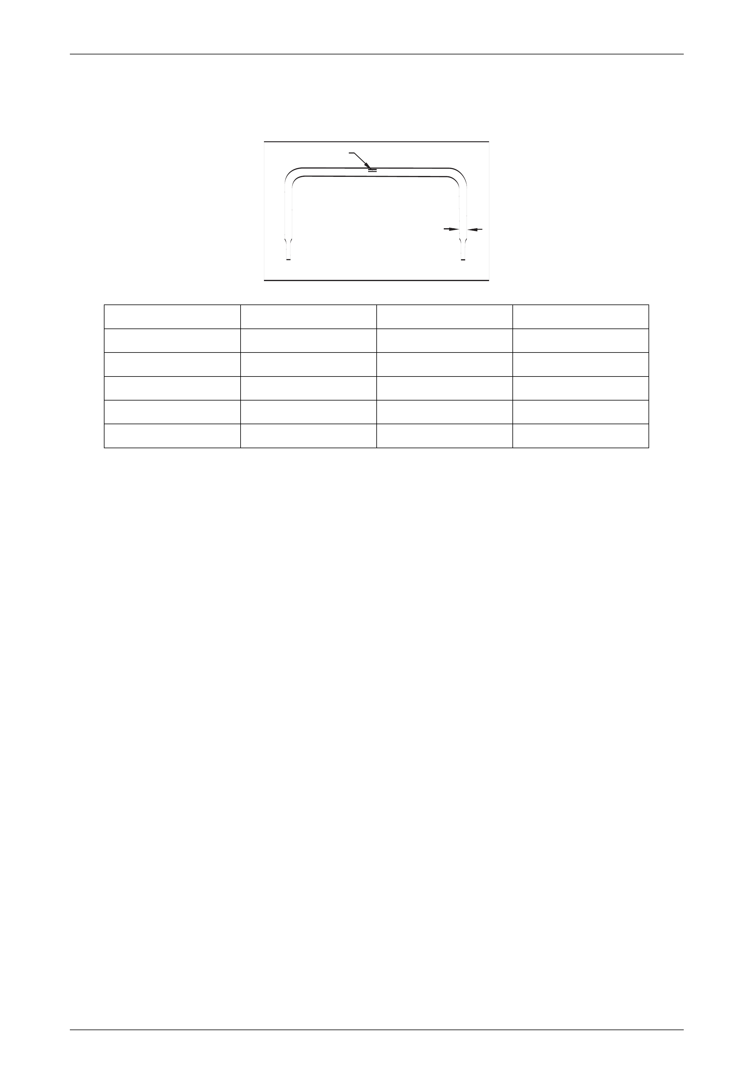
Front Spring Detail
Identification of the front spring fitted to a particular vehicle can be achieved by cross-refe rencing the label details (1) with
the table below.
Model Free Length
(mm) Spring Type and Rate Part Number Production ID
Code
Touring 328 Variable 25-34 N/mm
(4000 ± 110 N @ 179 mm) 03C-020601 Grey Label
Performance 328 Variable 25-34 N/mm
(4000 ± 110 N @ 179 mm) 03C-020601 Grey Label
Touring (Maloo) 328 Variable 25-34 N/mm
(4000 ± 110 N @ 179 mm) 03C-020601 Grey Label
Luxury 328 Variable 25-34 N/mm
(4000 ± 110 N @ 179 mm) 03C-020601 Grey Label
Ohlins 328 Variable 25-34 N/mm
(4000 ± 110 N @ 179 mm) 03C-020601 Grey Label
Suspension Page C-7
Page C-7
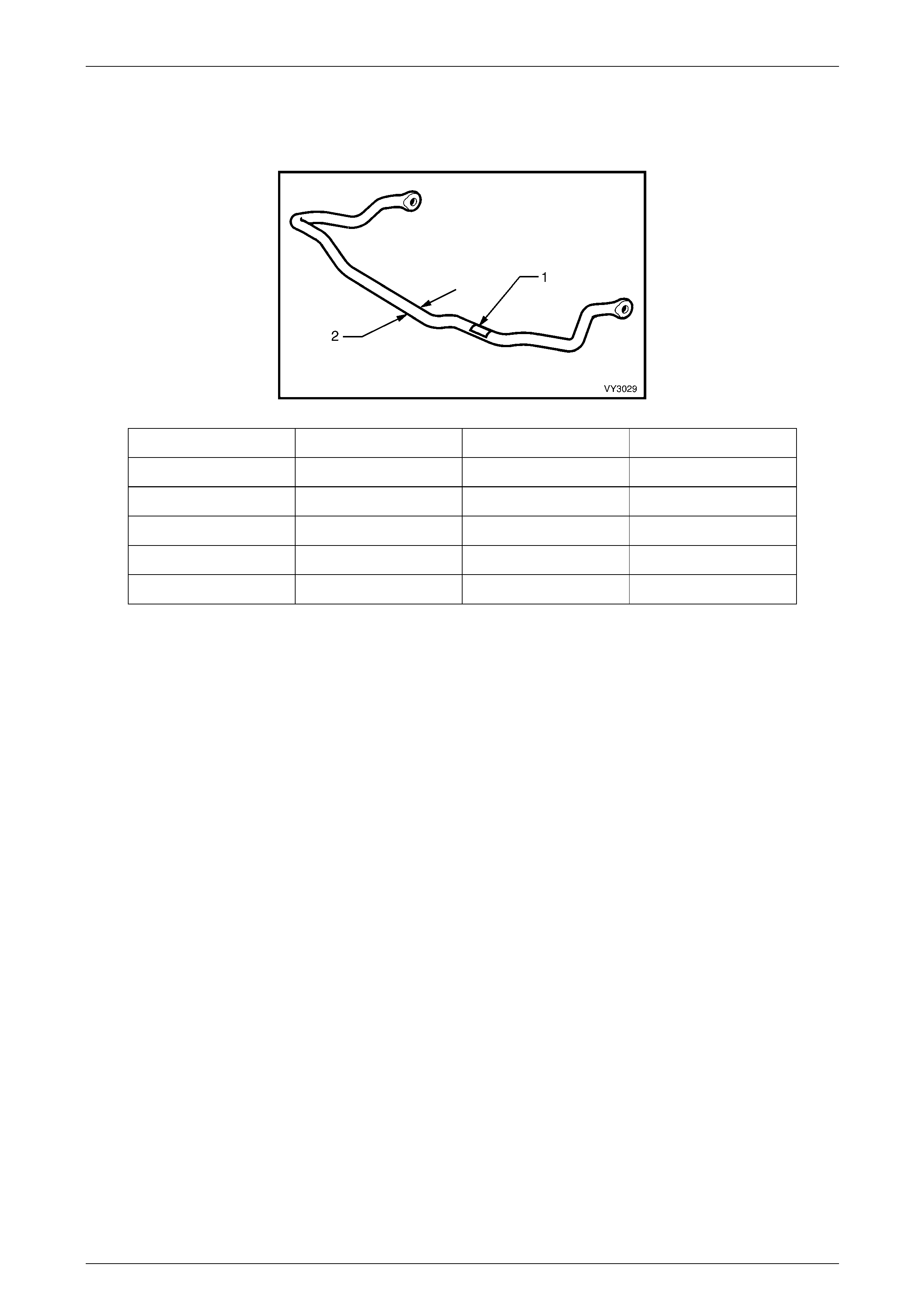
Front Stabiliser Bar Detail
Identification of the front stabili zer shaft fitted to a particular vehicle can be achi eved by cross-referencing the two-digit
production identification tag (1) with the table below. The table also provi des the shaft diameter (2).
Model Diameter (mm) Part Number Production ID Code
Touring 28 92111615 AA
Performance 28 92111615 AA
Touring (Maloo) 28 92111615 AA
Luxury 28 92111615 AA
Ohlins 28 92111615 AA

Suspension Page C-8
Page C-8
3 Rear Suspension
3.1 General Information
Rear suspension assemblies fitted to HSV VZ models are similar to Holden VZ models with the exception of HSV
specific components which are detailed in the follo wing tables and i llustrations.

Suspension Page C-9
Page C-9
3.2 Service Operations
Service Operations and Service Intervals for HSV Rear Suspension assemblies are the same as those detailed in the
relevant Holden VZ Service Information except when detailed otherwise in this suppleme nt
Suspension Page C-10
Page C-10
3.3 Rear Suspension Components
The following HSV components are fitted to rear suspension assemblies as ind icate d:
Rear Spring Detail
Model Free Length (mm) Spring Type and Rate Part Number Production ID Code
Touring 250 Variable 43-90 N/mm
(4400 ± 110N @ 168 mm) 92048210 EM
Performance 250 Variable 43-90 N/mm
(4400 ± 110N @ 168 mm) 92048210 EM
Touring (Maloo) 262 Variable 46-95 N/mm
(5500 ± 110N @ 152 mm) 04B-010501 Blue Label
Luxury 273 Variable 40-50 N/mm
(5500 ± 110N @ 139 mm) 04B-970801 Brown Label
Ohlins 250 Variable 43-90 N/mm
(4400 ± 110N @ 168 mm) 92048210 EM
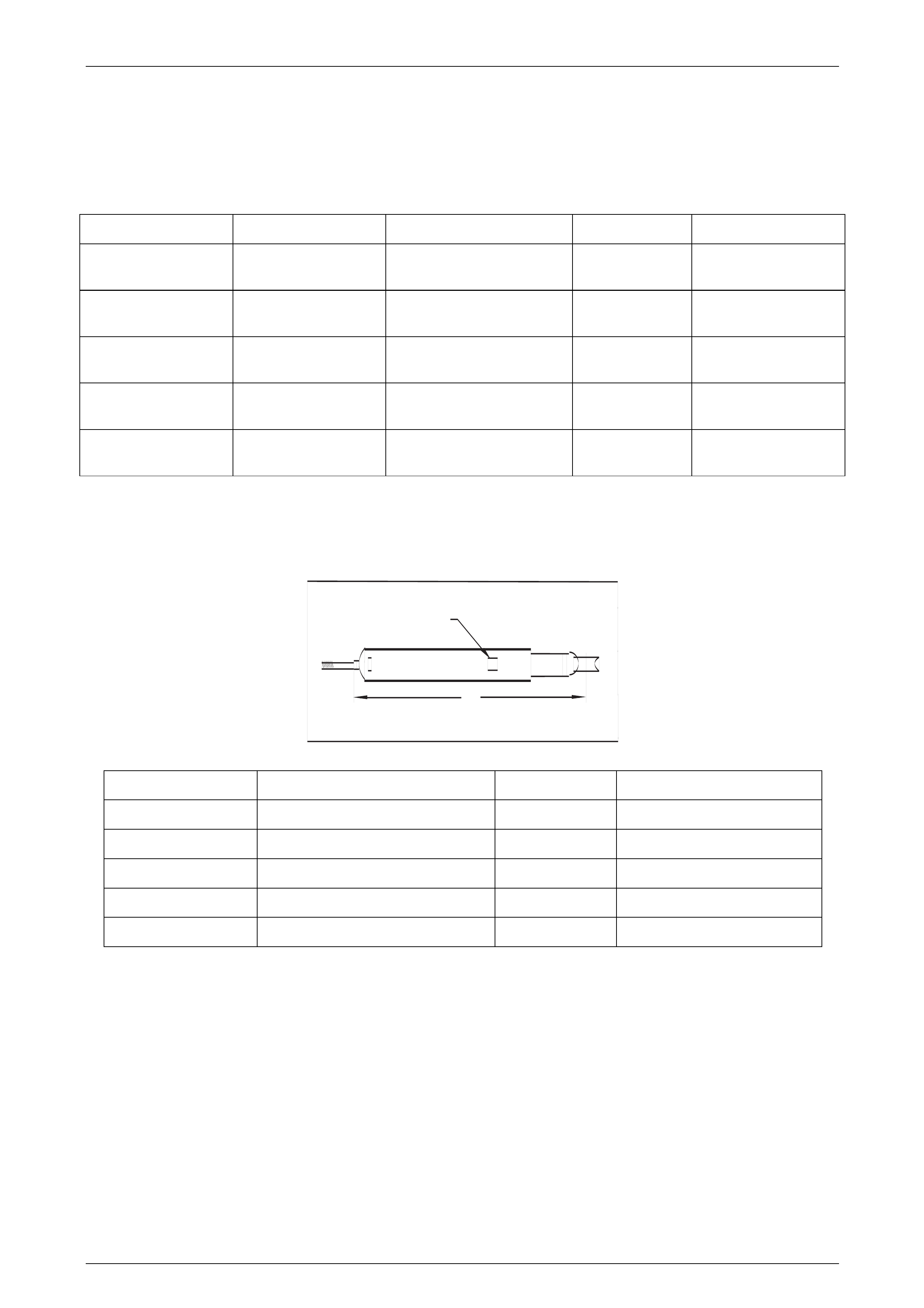
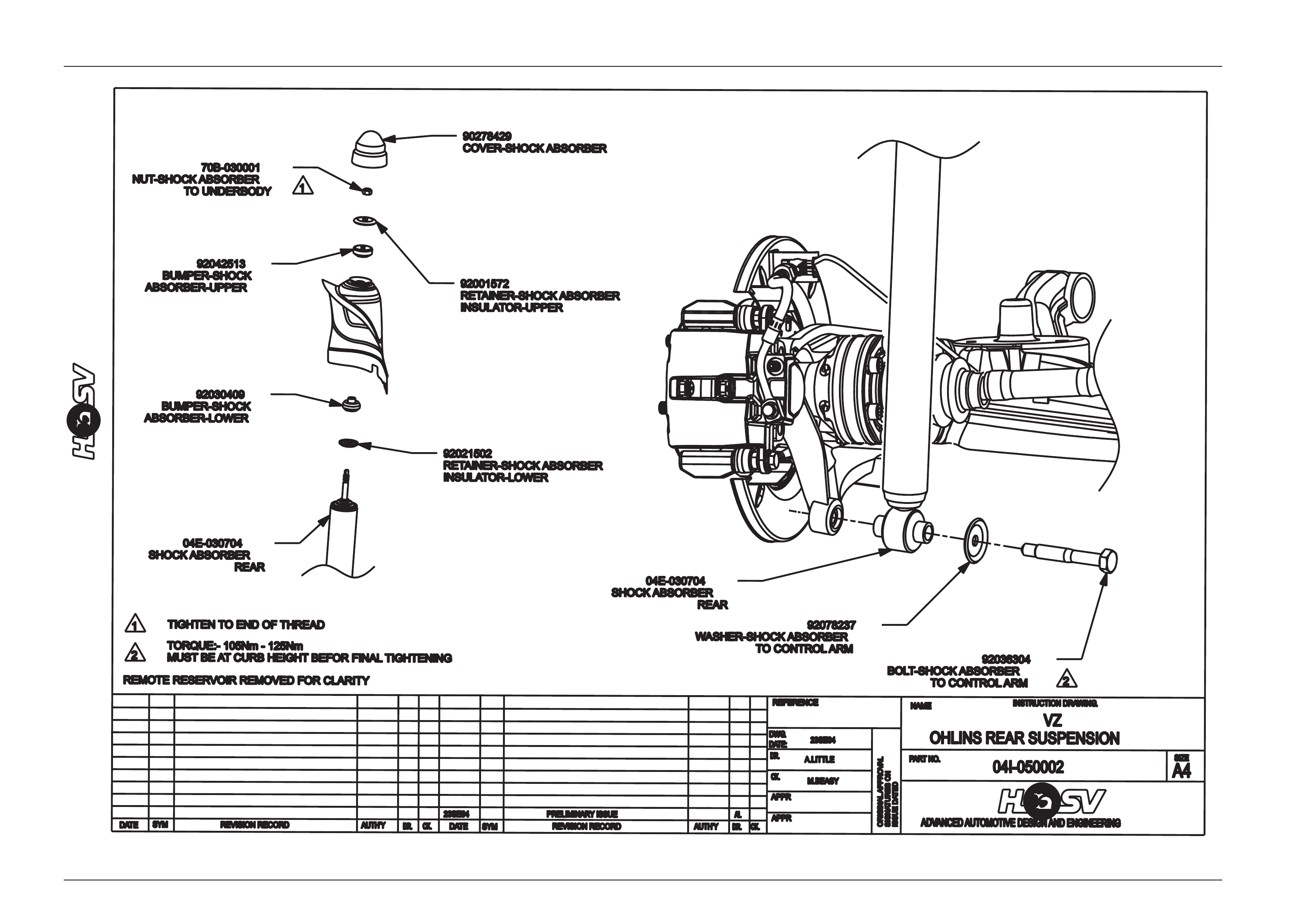
Rear Shock Absorber Detail
Type.............................................................................Twin Tube Hydraulic, gas pressurized.
Identification of the rear shock absorber fitted to a particular vehicle can be achieved by cross referencing either the
stamped in part number (see lower damper tube), or production identification code (1) with the table below.
A
1
Model Nominal Extended Length (A) Part Number Production ID Code
Touring 670 04E-030601 TY2
Performance 670 04E-030703 PY2
Touring (Maloo) 536 04E-030501 MY2
Luxury 670 04E-031601 LY2
Ohlins 670 04E-030704 No ID Code “Ohlins”
Suspension Page C-11
Page C-11
Rear Stabiliser Bar Detail
Identification of the rear stabiliz er shaft fitted to a particular vehicle can be achieved by cross-referencing the two digit
production identification tag (1) with the table below. The table also provi des the shaft diameter (2).
1
2
Model Diameter Part Number Production ID Code
Touring 15 92048230 FJ
Performance 15 92048230 FJ
Touring(Maloo) 14 04F-010503 No Marking
Luxury 15 92048230 FJ
Ohlins 15 92048230 FJ
Suspension Page C-12
Page C-12
4 Suspension Ohlins Supplement
4.1 General Information
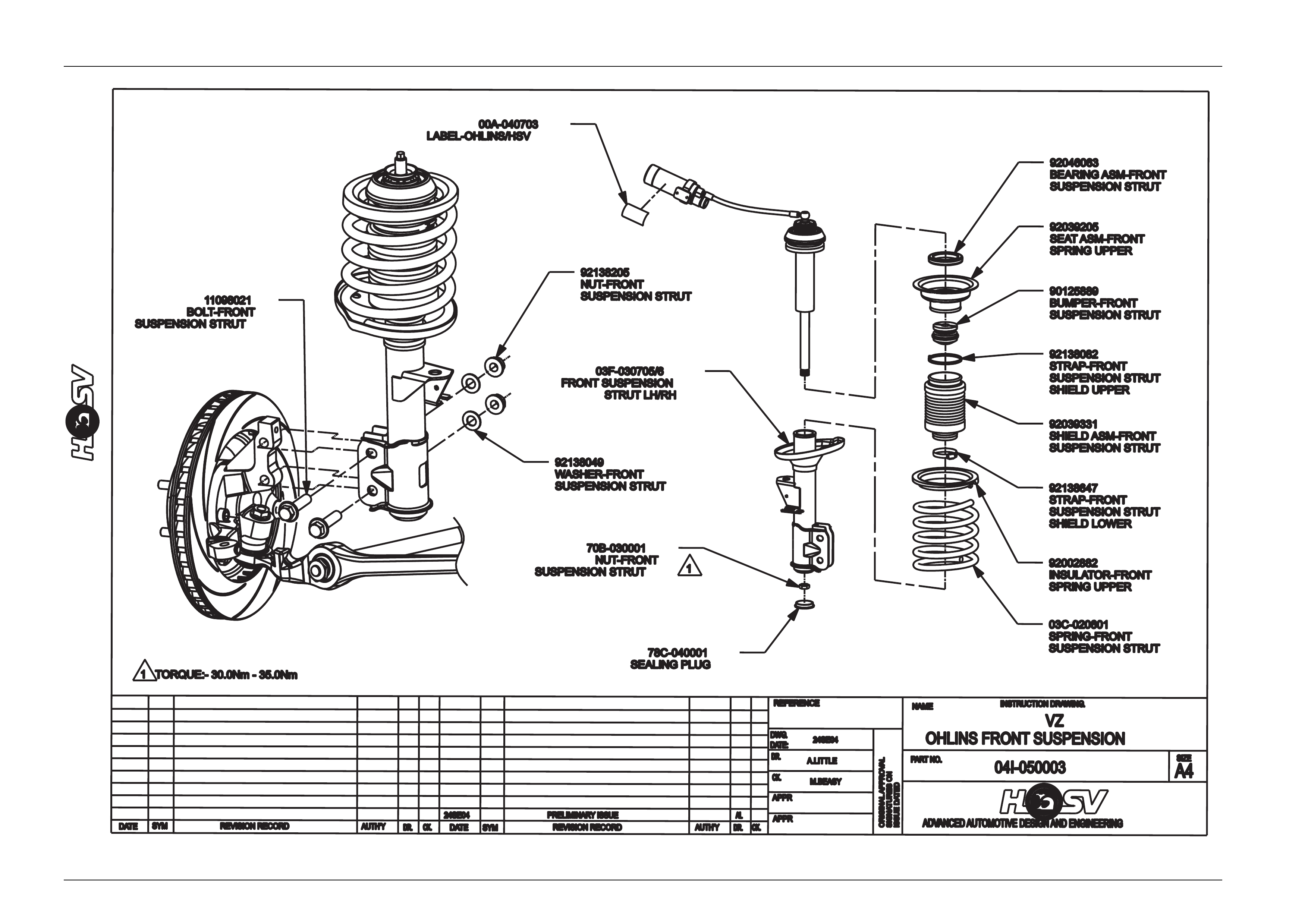
The purpose of this supplement is to provide information on the new Ohlins Adjustab le Performance Suspension optional
on VZ Clubsport and GTO Coupe
The Ohlins system consists of oil filled front struts and rear shock absorbers that have adjustable bump and rebound
settings. Adjustment is carried out via knobs fitted to each shock absorber a ssembly. Removal and replacement of the
front strut and rear shock absorber is similar to the Holden suspension systems with the exception of front strut hoses
and canisters which are mounted on the front strut brace in the engine bay. Refer to instruction drawings
04I-050003, 04I-050004 and 04I-050002.
The front mounting is a unique adaptation of the Monroe front strut with a HSV designed a nd developed upper mounting
system.
The rear dampers utilize the standard top and bottom shocker mounts. However as thes e units are fitted with external
gas canisters, the front canisters are supported on the strut brace in the engine bay. The rear can isters are a “piggy
back” unit and are affixed to the shocker.
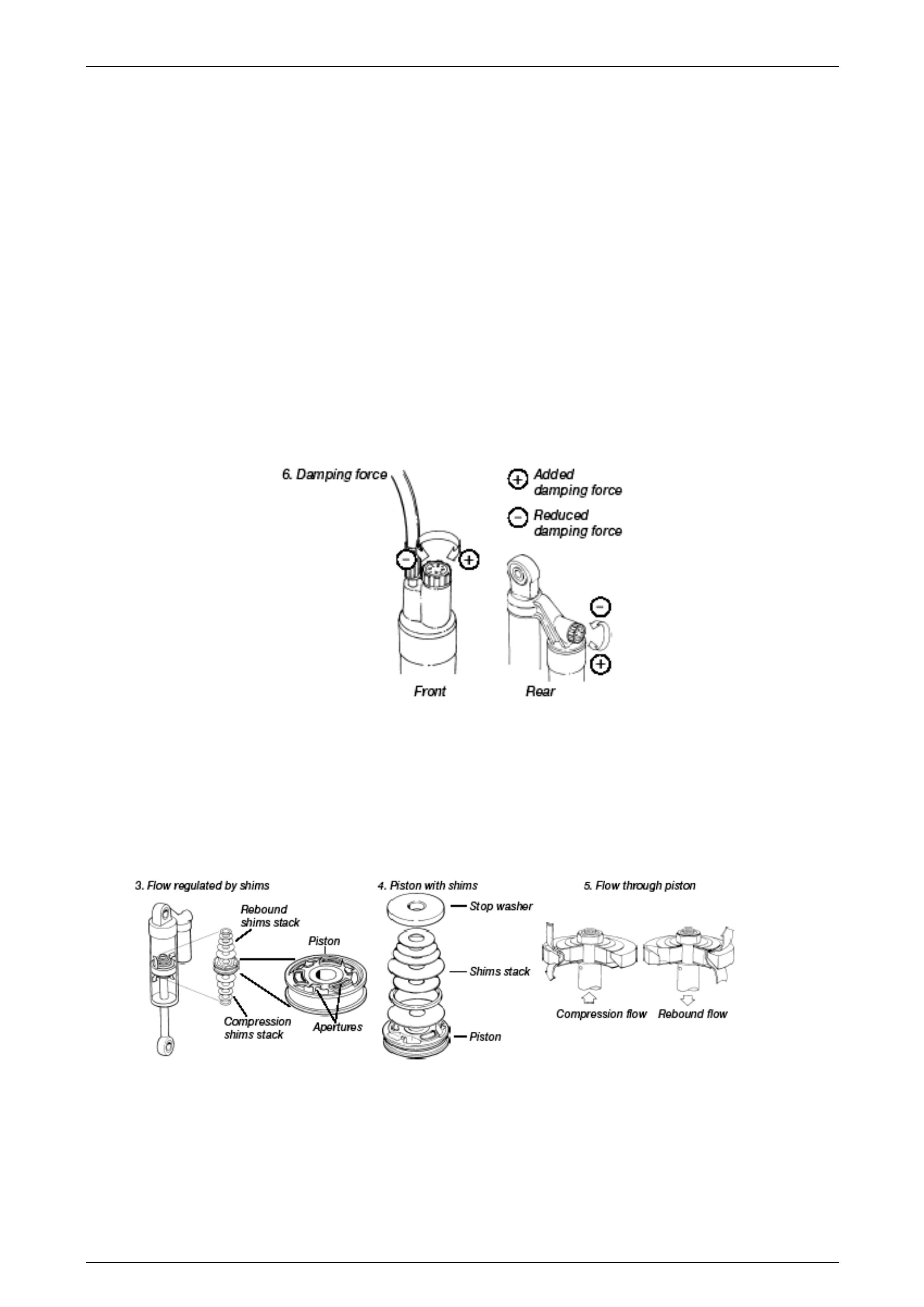
The adjustment knobs are located on the remote canister units. These knobs can be tur ned by hand clockwise to
increase damping force, or anti-clockwise to decrease dampi ng force.
When movement of the vehicle occurs, fluid flows through the apertures and shims, underneath and above the piston
(depending on whether a compression or a reboun d movement has occurred) .The fluid that has been displaced by the
volume of the rod is forced into the external fluid reservoir. The separatin g piston between the oil and th e gas has been
displaced and gas pressure increases. The result of the increased gas pre ssure against the rod and the oil flow through
the apertures in the shims provide the resistance to movement or damping. Gas is also used to help alleviate cavitation
in the oil.
Suspension Page C-13
Page C-13
4.2 Servicing/Inspection and Maintenance
Clean the shock absorbers external ly with a soft detergent. Lift the dust cover and use compressed air. Be careful that all
dirt and debris is removed. Lift the bump rubb er and clean the area below. Keep the shock absorbers clean and al ways
spray them with lubricant (CRC 5-56, WD 40 or similar).
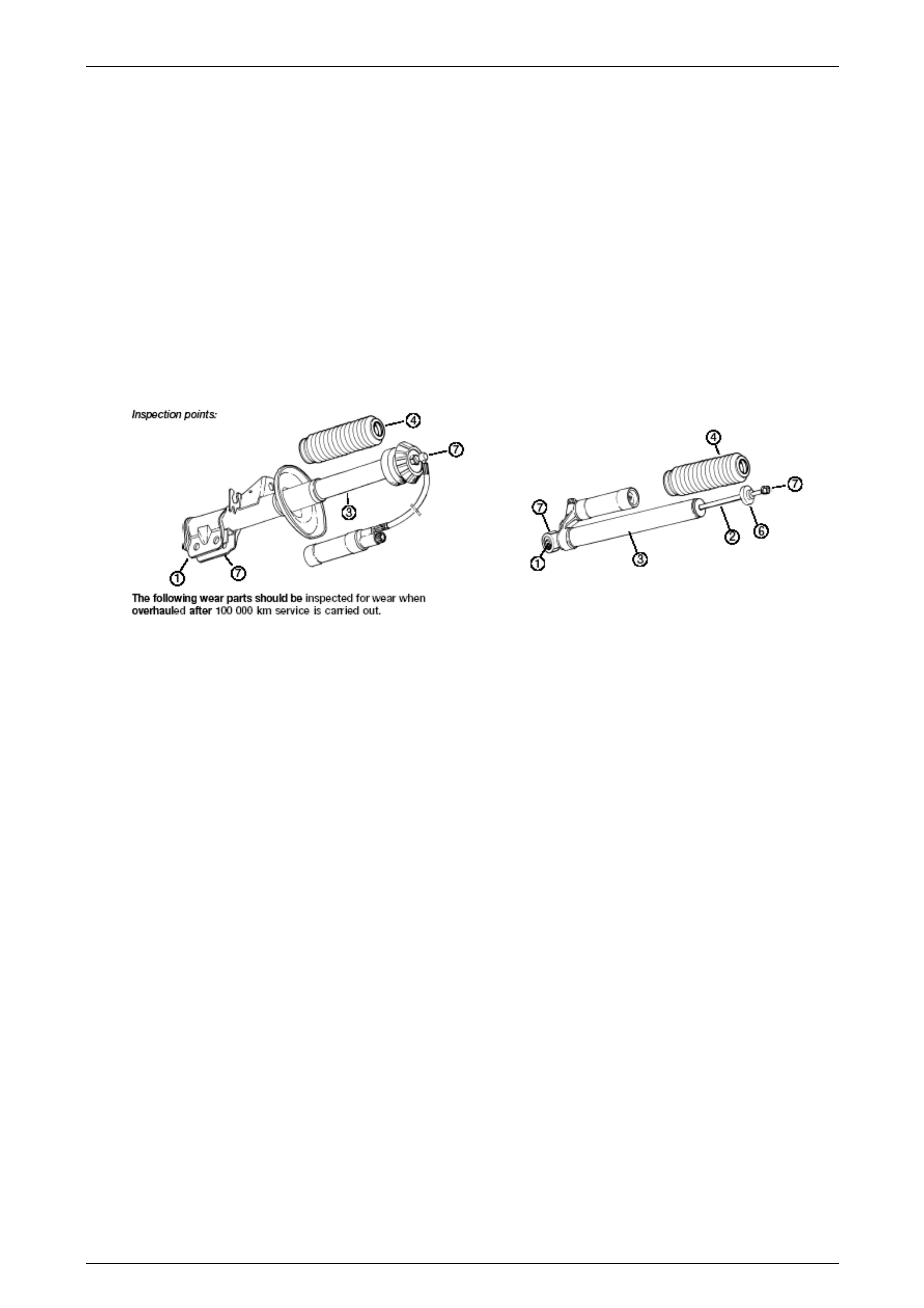
Inspection Points
1. Check brackets or bushes for possible excessive play.
2. Check the piston shaft for leakage or damage.
3. Check the shock absorber body for external damage.
4. Check the dust cover for damage.
5. Check the spring condition.
6. Check for excessive wear of rubber components and dust covers.
7. Check fastening points to vehicle.
Suspension Page C-14
Page C-14
Suspension Page C-15
Page C-15
Suspension Page C-16
Page C-16

Suspension Page C-17
Page C-17
5 Rear Final Drive and Drive
S hafts
5.1 General Information
All HSV models utilize up rated propell er an d drive shafts with a higher torque capacity to match the performance of the
unique LS2 engine.
Propeller and drive shaft diameters have b ee n increased, along with ne w propeller shaft flexible couplings with a larger
PCD for the bolt attachment arrangement.
The differential is a high torque capacity LSD with shot peened ge ar sets and all models have a 3.46:1 ratio to
complement the ratios in the ne w M12 version T56 manual and the M32 (4L65E-HMD) automatic transmission.
The final drive and drive shafts fitted to MY 2005 HSV VZ vehicles, carries over from
MY 2005 Holden VZ vehicles, except for the following items:
• With the increased output from the GEN IV V8 (LS2) engine, both the front and rear propeller shaft rubber
couplings have larger d iamete r s. T his has resulted in an increased pitch circle diameter (PCD) change from 96 to
110 mm for the attaching bolts.
• With the increased PCD for the propeller shaft rubber couplings, a revised design final drive pin ion flange is now
fitted, that results in two new special tools being release d. These tools are used to:
a Hold the pinion flange when loosening/tightening the pinion flange nut.
b Remove the pinion flange from the final drive pinion when replacin g the flange, the oil seal or when
undertaking a final drive overh aul procedure.
Both new tools have the earlier and later PC D dimension holes included, which allows them to be used on this and
earlier model vehicles. The procedure for fitment and use of these new tools is the same as detailed in the Holden
VZ Service Information, Section 4B Final Drive and Drive S hafts.
Refer to 7 Special Tools in this Section for the new tool details.
• To enable the final drive p inion bearing preload to be measured, the fabricated wooden disc requir es some
modification to allow it to be used on th e revised diameter pinion flange. R efer to 7 Special Tools in this Section for
the necessary changes.
• Both drive sh afts are now fitted with a plunge type constant velocity joint at the inner a nd outer locations.
This means that the same servicing procedu re for the inner constant velocity joint (plunge type) detailed in the MY
2005 Holden VZ Service Information, Section 4B1 Fina l Drive and Drive Shafts, can now be adopted for any of the
four, drive shaft constant velocity joints fitted to MY 2004 HSV VZ vehicles.
• A revised procedure has been developed to select the hypoid pinion p ositioning shim. This has resulted in a
changed dimension spac er to be used, which is incorporated into pinion set gauge kit, tool number DT-47737. In
addition, with the changed dimensions of the inner pinion bearing, a revised tool has been developed to remove the
bearing cup from the final driv e housing. Details of these revised tools and the procedures relating to their use is
provided here, in the sub-section, "Hypoid Pinion Shim Sel ection" and "Pinion Installation".
Suspension Page C-18
Page C-18
5.2 Major Service Operations
Final Drive Assembly Unit Repair
Reassemble
Hypoid Pinion Shim Selection
The pinion posit ioning shim is located between pinion rear (inner) bearing cup and carrier housing.
If the ring gear and pinion or the pinion rear bear ing assembly are replaced, pinion depth must be rechecked with pinion
setting gauge, Tool No. DT-47737. This set includes a dummy pinion spac er, T ool No. DT-47696 and dummy arbour
Tool No. AU408.
The gauge and arbour pr ovide a nominal or 'zero' pin ion as a gauging reference.
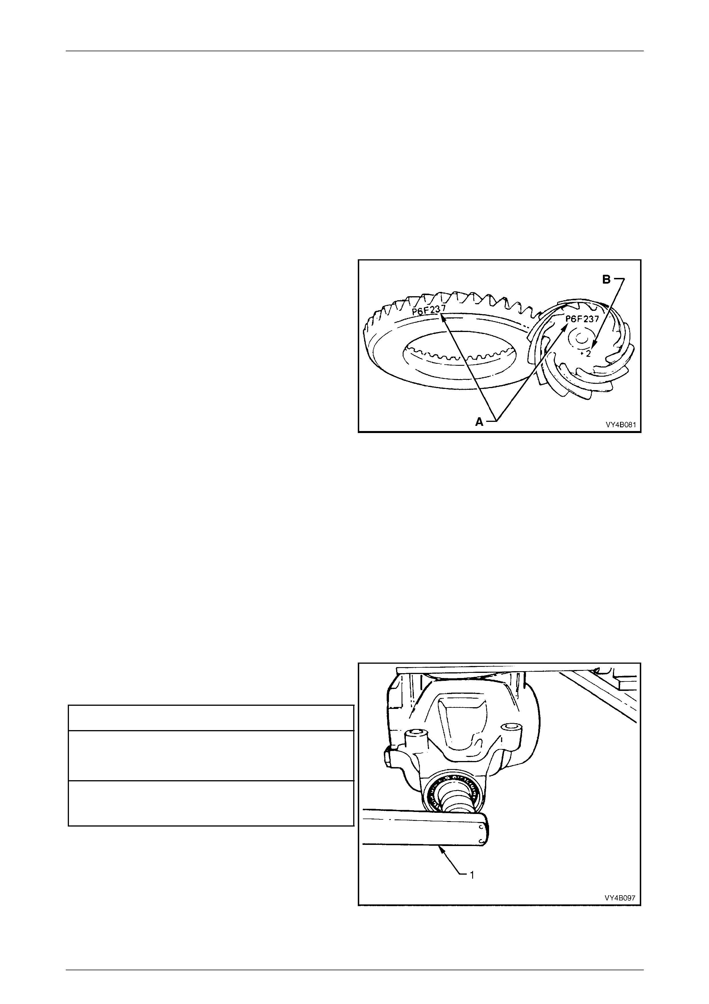
NOTES
• If a new gear set is to be installed, check that
the same matching number (‘A’) appears on
both the pinion and the ring gear, with either
a white or yellow marker.
• The pinion installation marking figure is
indicated by ‘B’, again with either a white or
yellow marker.
Figure C – 1
1 Inspect pinion bearing cups/c ones for nicks and burrs. Replace if damage d.
2 Lubricate pinion front and re ar bearings with the recommen ded differential carrier lubricant. Do not use engine or
other oils, as a misleading rotating torque can be obtained.
NOTE
Make sure that both pinion bearings used on the
dummy pinion to determine the pinion positio ning
shim thickness, are those t hat will be used on the
final reassembly.
3 Install the spacer, Tool No. DT-47696, to the dummy pinion, supplied as part of DT-47737, then install the rear
(inner) pinion bearing onto the dumm y pin ion.
4 Install dummy pinion and rear (inner) bearing into the carrier housing. Fit front (outer) bearing to dummy pinion,
then install the dummy pinion thrust collar and nut (included in pinion set gauge kit DT-47737).
5 Tighten nut on end of dummy pinion, using a
commercially availabl e, dial type torque wrench (1),
until the specified rotational torque is obtaine d.
Dummy Pinion Rotational Torq u e Sp ecification
New Bearings (No Pinion Oil Seal Installed)
Timken Koyo
1.4 – 2.0 N.m 1.5 – 1.9 N.m
Used Bearings (No Pinion Oil Seal Installed)
Timken Koyo
0.7 – 1.2 N.m 0.7 – 1.2 N.m
6 Rotate dummy pinion back and forth during tightening
to ensure that bearings settle in their cups.
Figure C – 2
Suspension Page C-19
Page C-19
NOTES
• Once the specified preload is reached,
remove the gauge block from the rear of the
dummy pinion (that al lo wed the p ini on be arin g
preload tightening process to be done).
Rotate the pinion approximately 50 turns in
each direction, then re-check the bearing
preload, readjusting as required, to achieve
the specified figure.
• Pinion bearing pre-load is very important
because it retains the pinion in its correct
relationship to the ring gear.
• Bearings that are installed with insufficient or
no pre-load will, after a comparatively short
period of running, develop end play. This will
cause noisy operation on overrun and could
be responsible for scuffing of the ring gear
and pinion teeth.
• Bearings that have too much pre-load, may
become pitted or flaked and result in
premature failure. It is therefore vital that
bearings are pre-loaded to the specified
torque specification.
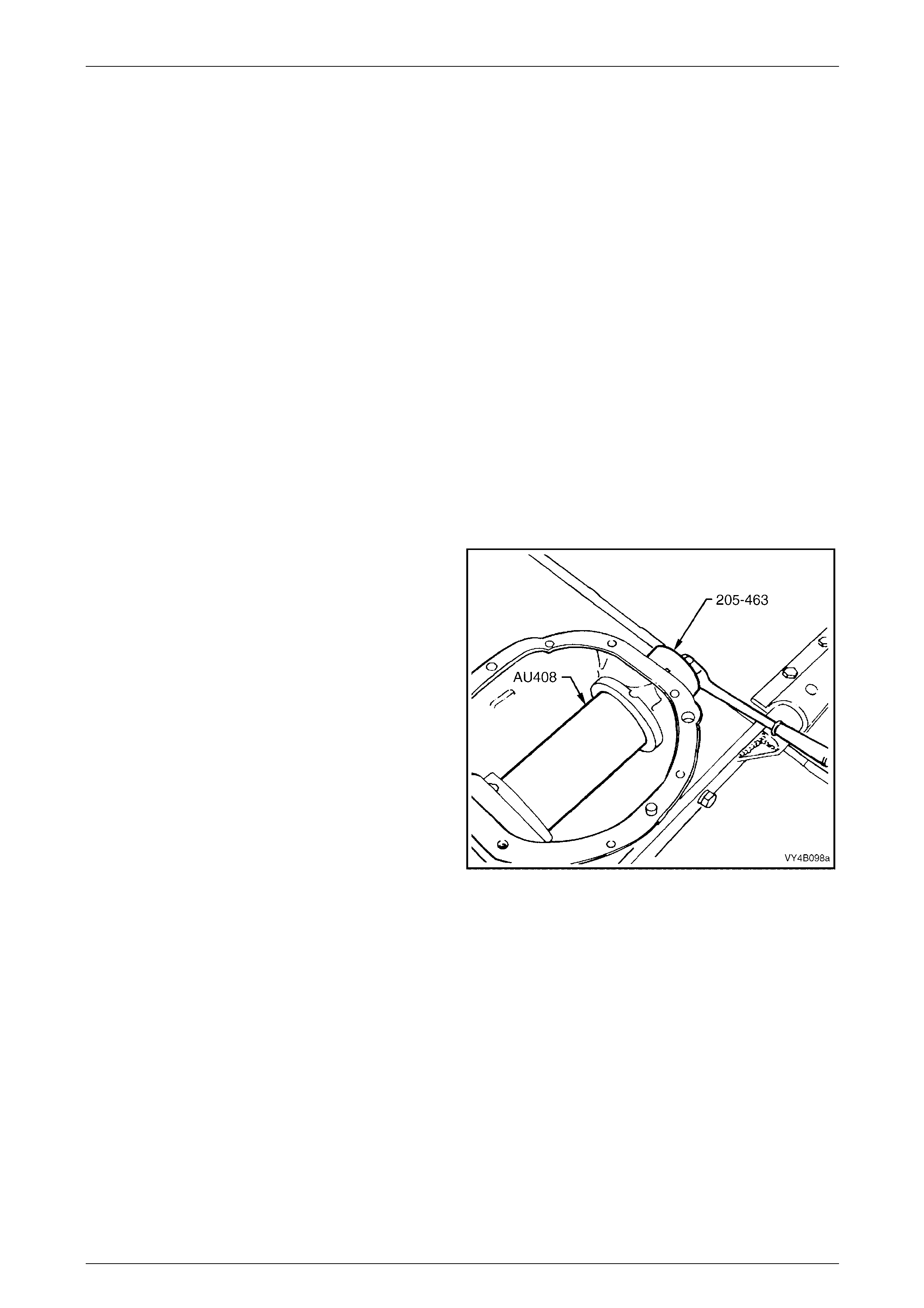
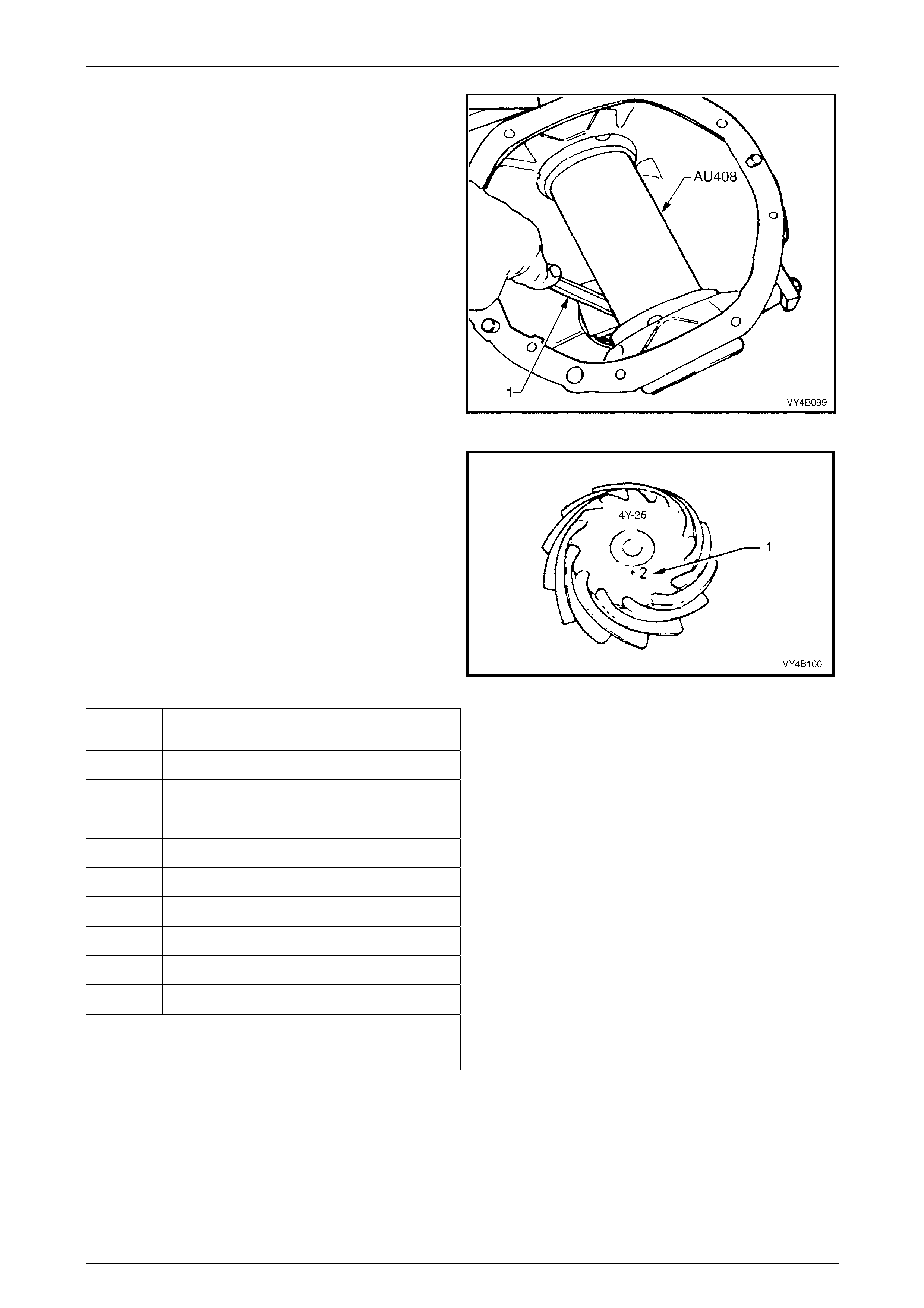
7 Position arbour Tool No. AU408 (part of pinion height
setting gauge, DT-47737) in c arrier assembly and
install screw adjusters with side bearing cup s . Adjust
screw adjusters to lightly clamp arbour, using Tool No.
205-463.
NOTE
Ensure that arbour is free of any burrs that may
damage bearing cups.
Figure C – 3
Suspension Page C-20
Page C-20
8 Check clearance between arbour (Tool No. AU408)
and head of dummy pinion with a feeler gauge (1).
Record this dimension.
Figure C – 4
9 On the end of the pinion, a drive pinion installation
marking figure (1) is applied with either a white or
yellow marker. A zero marking ('0') indicates that shim
size equal to the dimension measur ed in Step 8 is the
correct size for this carrier/pinion combination.
A positive marking, e.g. +3, means that a thickness
measurement equivalent to this numerical marking
must be subtracted from shim size measured in
Step 8. Refer to the following chart for specific details.
A negative marking, e.g. –3, means that a thickn ess
measurement equivalent to this numerical marking
must be added to the shim size measured in Step 8.
Refer to the following chart for specific details.
Figure C – 5
Pinion
Marking Shim Thickness
Required
– 4 Add 0.100 mm to the Step 9 measurement
– 3 Add 0.075 mm to the Step 9 measurement.
– 2 Add 0.050 mm to the Step 9 measurement.
– 1 Add 0.025 mm to the Step 9 measurement.
0 Size as measured in Step 9.
+ 1 Subtract 0.025 mm from the Step 9 measurement.
+ 2 Subtract 0.050 mm from the Step 9 measurement
+ 3 Subtract 0.075 mm from the Step 9 measurement.
+ 4 Subtract 0.100 mm from the Step 9 measurement
Pinion positioning shims are serviced in thicknesses of 0.2 mm
to 0.75 mm in 0.025 mm increments. They are also dimensioned
differently, depending on the pinion bearing used.
10 Remove dummy pinion and arbour from carrier assembly.
Suspension Page C-21
Page C-21
Pinion Installation
1 Select pinion positioning shim stack as determined in
the Hypoid Pinion Positioni ng Shim Selection
procedure, in this Section.
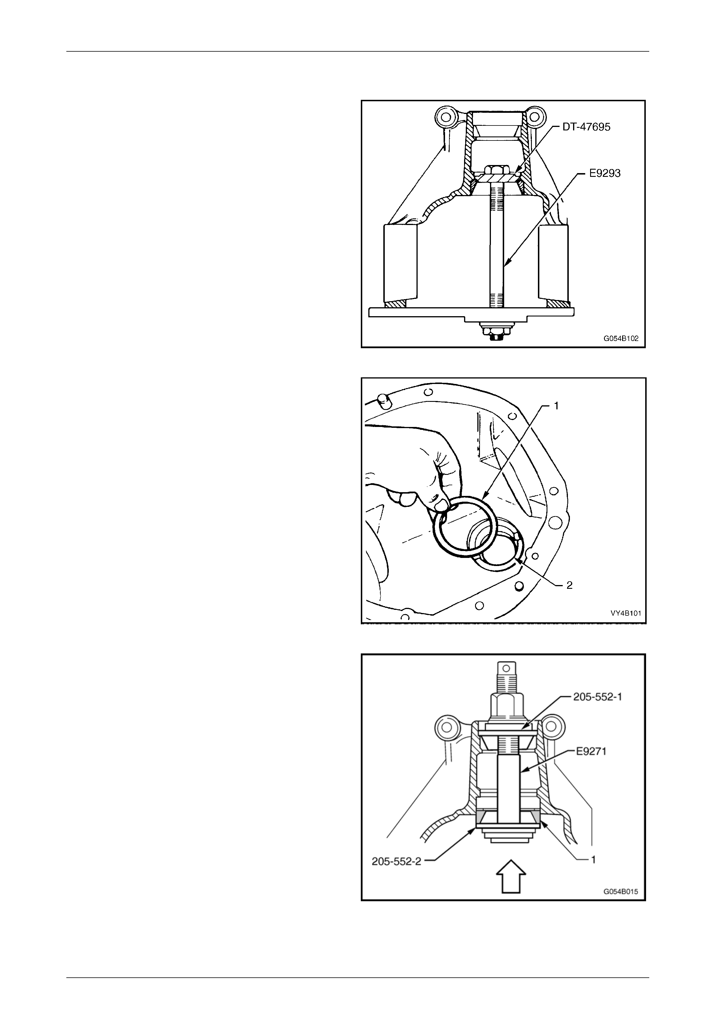
2 Remove pinion rear (inner) bearing cup, using Tool
No. E9293 and adaptor, Tool No. DT-47695.
Figure C – 6
3 Install the selected pinion positioning shim/s (1) into
pinion rear bearing cu p bore (2).
Figure C – 7
4 Reinstall pinion rear (inner) bearing cup using Tool No.
E9271 and adaptors 205-552-1 and 205-552-2.
Figure C – 8
Suspension Page C-22
Page C-22
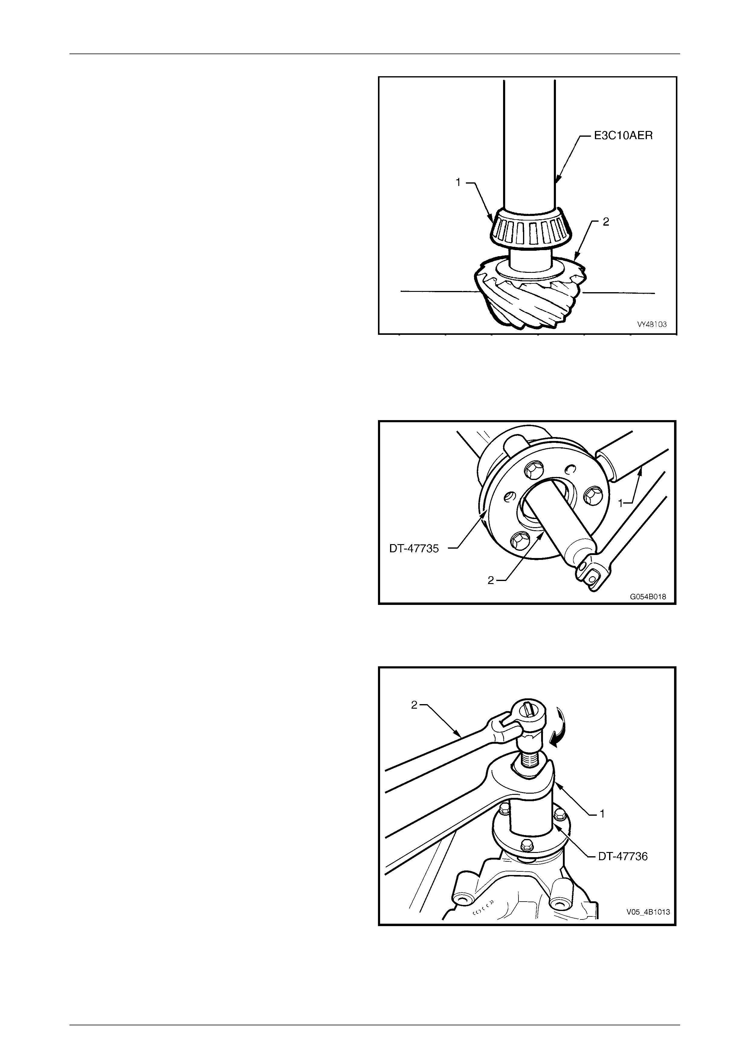
5 Press rear bearing inner race aga inst the shoulder of
the pinion, using Tool No. E3C10AE R.
NOTES
• To avoid possible damage to the pinion gear
teeth when pressing the bearing on, ensure
that the press plates are perfectly flat, free of
burrs and foreign matter prior to installing the
rear bearing.
• Locate bearing inner race squarely on the
pinion and press only on inner race surface.
• Only lubricate the bearing with the
recommended differential carrier lubricant.
Figure C – 9
6 Place the pinion in the carrier.
7 Lubricate pinion front bearing with the recommended differential carrier lubricant and assemble the collapsible
pinion bearing spacer and front bearing onto pini on, while supporting pinion head.
8 Install pinion flange and the o r iginal pinion flang e
retaining nut.
9 Install Tool No. DT-47735 to the pinion flange.
NOTE
Use either the rear coupling to pinion flange
retaining bolts with a 25 mm spacer (e.g. flat
washers) installed first or use three bolts M12 x
1.5 x 40, with the thread extending to within 12
mm of the head.
10 Using a suitable length of pipe (1) to over the hol ding
tool tang, tighten retaining nut until pinion front beari ng
is squarely engaged on the pinion shaft and not
cocked.
11. Remove the pinion flange retaini ng nut, using a
commercially availabl e, 30 mm deep socket (2) and
socket bar.
Figure C – 10
12 Install extractor, Tool No. DT-47736 to the pinion
flange using the same three b olts used to se cure the
flange holding tool, DT-47735 (refer step 9).
13 While holding the extractor tool with a suitable spanner
(1), withdraw pinion flange by tightening the forcin g
screw in the direction indicated, using suitable socket
equipment (2).
Figure C – 11
Suspension Page C-23
Page C-23
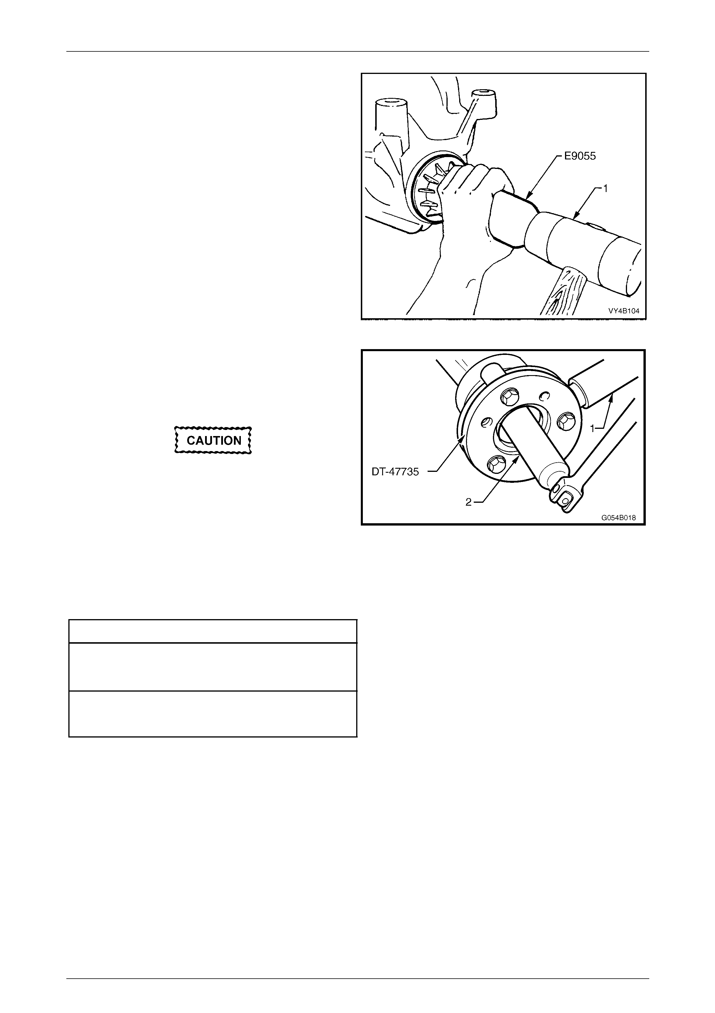
14 Lubricate pinio n oil seal lips and the pinion oil seal
bore in the carrier housing with Mobilgrease XHP 222
or equivalent grease.
15 Install oil seal into carrier bore using T ool No. E9055
and a plastic faced hammer (1) until the seal fits flush
to 0.25 mm below carrier housing surface.
Figure C – 12
16 Reinstall pinion flange and fit a NEW retaining nut.
17 Hold pinion flange using Tool No. DT-47735 and a
suitable length of pipe (1).
18 Gradually tighten the retaining nut while rotating pi nion
in both directions to seat bearings.
If the retaining nut is over-tightened and pre-
load exceeded, it will be necessar y to remo ve
the pinion from the carrier and a new
collapsible spacer installed. Under no
circumstances must the retaining nut be
backed off to decrease the pre-load reading. Figure C – 13
19 Check bearing pre-load freq uently by removing flange holding tool (DT- 47735) and installing a pulley and string to
the pinion flange. Refer to 7 Special Tools at the end of this Section for pulley details.
20 Using a spring scale, measure rotationa l torque.
21 Continue to tighten the nut until specified torque is achieved.
Pinion Rotational To rqu e Specification
New Bearings (With Pinion Oil Seal Installed )
Timken Koyo
1.4 – 2.4 N.m 1.5 – 2.1 N.m
Used Bearings (With Pinion Oil Seal Installed)
Timken Koyo
0.7 – 1.2 N.m 0.7 – 1.2 N.m
22 The torque figure is calculated b y multiplying the radius of the pulley by the spring balance reading.
Example: If the pulley diameter is 152 mm, the radius is 76 mm which equals 0.076 m. The spring b ala nce reading is
25 N. Therefore, the pre-load equals 0.076 m x 25 N = 1.9 Nm.
Suspension Page C-24
Page C-24
5.3 Pinion Flange
Replace (Vehicles With a Rear Rubber Coupling)
ATTENTION
The following fasteners MU ST be replaced when performin g these operations:
Drive shaft attaching bolts.
Using Old Oil Seal
Resulting from production tolerances in the
length of the pinion flange, it is essential that
the following method be used when installing
a new pinion flange.
1 Raise the vehicle and suppor t in a safe manner. Refer to Section 0A General Information in this Service Information
for the location of recommended lifting and supp ort points.
2 Remove propeller shaft, refer Section 4C1 Propeller Shaft and Universa l Joints , in the MY 2005 VZ Series Service
Information.
3 Remove both drive shafts, refer to Section 4B1 Final Dr ive and Drive Shafts in the MY 2005 VZ Series Service
Information.
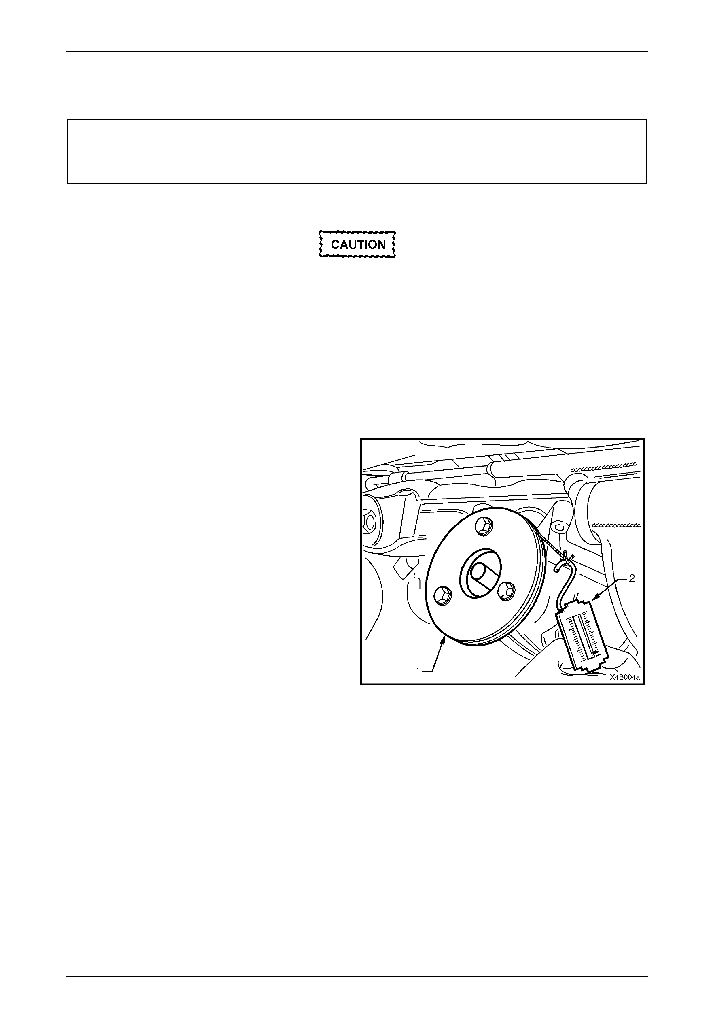
4 Check and record pre-load at pini on flange as follows:
a Fit a pulley (1) to pinion flange, using three
suitable bolts and attach a cord around p ulley
and to a spring scale (2).
NOTE
• Use either the rear coupling to pinion flange
retaining bolts with a 25 mm spacer (e.g. flat
washers) installed first or use three bolts M12
x 1.5 x 40, with the thread ext ending to within
12 mm of the head.
• For details of the fabricated pulley, refer
7 Special Tools at end of this Section.
b Start rotation of pulley and whilst in motion
(approximately 50-60 rpm) note and record
reading of spring balance.
This pre-load reading includes pinion beari ngs,
side bearings, meshing effect of gear set and
pinion oil seal.
To determine pre-load, multipl y readi ng on
spring balance by radius of pulley. Figure C – 14
Suspension Page C-25
Page C-25
Example: With a pulley diameter of 152 mm, the radius is 76 mm, which equals 0.076 m. With a spring balance readi ng
of 25 N, the pre-load equals 0.076 m x 25 N = 1.9 Nm.
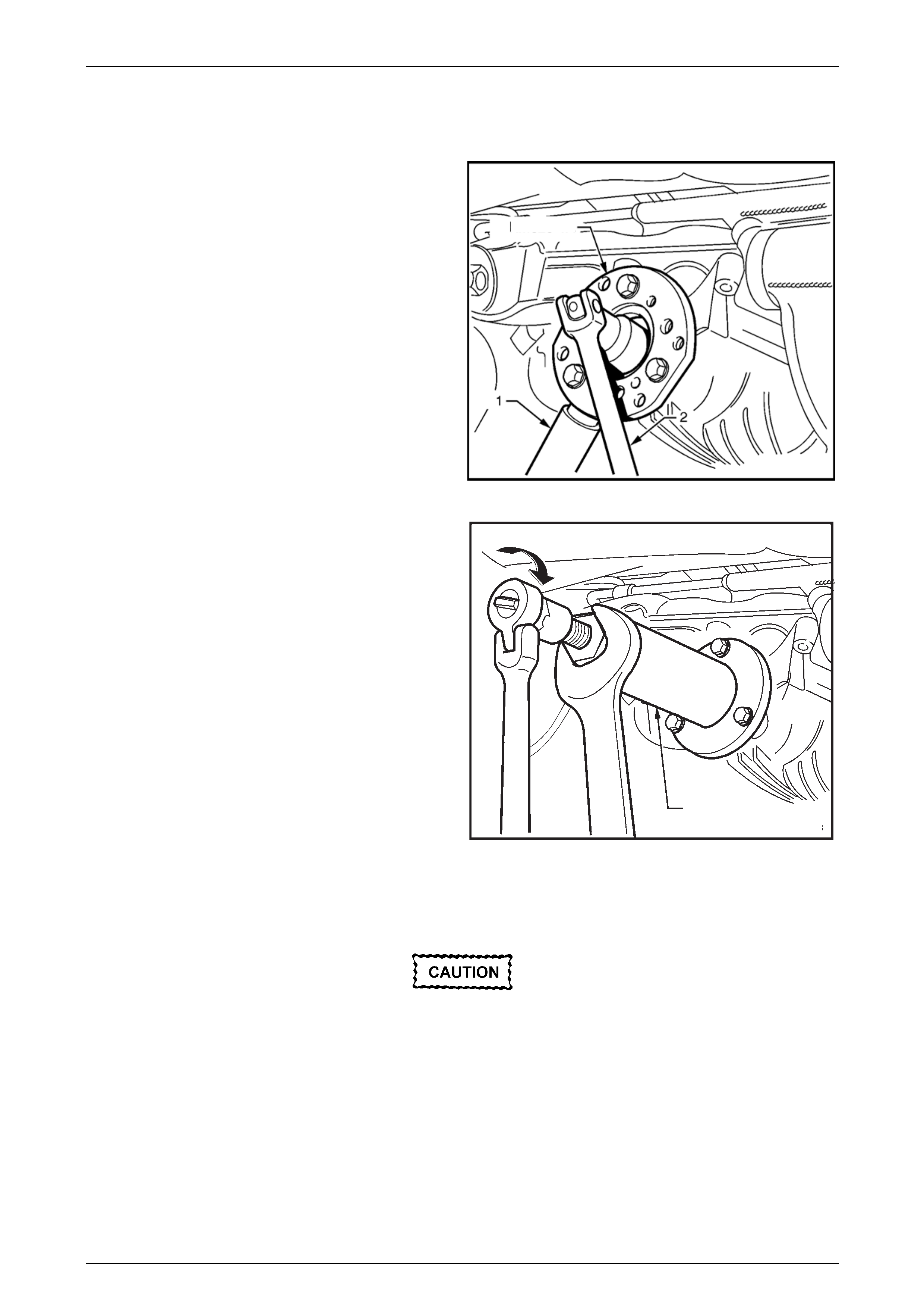
5 Remove pulley from pinion flange.
6 Attach Tool No. DT-47735 to the pinion flange, using
three suitable bolts to hold pinion flange.
NOTE
• If not done before, drill out holes stamped ‘B’
on Tool No. DT-47735 to 12.5 mm.
• Use either the rear coupling to pinion flange
retaining bolts with a 25 mm spacer (e.g. flat
washers) installed first or use three bolts M12
x 1.5 x 40, with the thread ext ending to within
12 mm of the head.
7 Insert a suitable length of pipe (1) over the tang of the
installed tool for leverage, then remove the pinion
flange retaining nut, using a commercia lly available,
30 mm deep socket and socket bar (2).
8 Remove Tool No. DT -47735 from the pinion flange.
DT- 47735
Figure C – 15
9 Place drain tray beneath differential carrier.
10 Install extractor, Tool No. DT - 47736 to the p inion
flange using the same three bolts used in step 6.
NOTE
• If not done before, drill out holes stamped ‘B’
on Tool No. DT - 47736 to 12.5 mm.
• If using the original propeller shaft coupling
bolts, they must have a 25 mm spacer fitted
to each, so the tool is clamped to the pinion
flange. If this is not done, the screw thread
on the extractor Tool No. DT - 47736 will not
be long enough to fully remove the pinion
flange.
11 While holding the extractor tool with a suitable
spanner, withdraw pinion flange by tightening the
forcing screw in the direction shown.
DT - 47736
Figure C – 16
12 Ensure that pinion shaft thread is free from burrs, oil, dirt or grease, then coat splines and seal surface of a new
pinion flange with the recommend ed rear axle lubricant.
13 Install the new pinion flange a nd a new retaining nut.
The pinion flange is an interference fit on
pinion shaft splines and should only be pulled
into place by tightening the retaining nut. Do
not used force or a hammer the flange during
the installation process.

Suspension Page C-26
Page C-26
14 Tighten flange retaining nut gradually until pinion shaft end play is reduced to approximately 0.50 mm.
Should the retaining nut be over-tightened
and the pre-load exceeded, it will be
necessary to remove the differential carrier
assembly and install a new collapsible
spacer. Under no circumstances must the
retaining nut be backed off to decrease the
pre-load setting.
15 Attach pulley to the new pinion flange and using a spring balance, check pre-load. Conti nue tightening nut while
alternatively turning pin io n to seat bearings, until the pre-load figure recorded previously (Step 4b) is reached.
Further increase this original pre-load reading by 0.5 Nm.
NOTE
Rotate pinion an extra 30 – 4 0 turns a nd r e-c heck
the preload to ensure that no change has
occurred.
16 Reinstall drive shafts, refer to Section 4B1 F inal Drive and Drive Shafts in the MY 2005 VZ Series Service
Information.
17 Reinstall propeller shaft, refer to Section 4C1 Propeller Shaft and Univ ersal Joints, in the MY 2005 VZ Series
Service Information.
18 If removed previously, reconnect exhaust system, in reverse to the removal procedur e.
Refer to Section 8B Exhaust System, in the MY 2005 VZ Series Service Information, for detai ls.
19 Lower vehicle to the ground.
20 Check lubricant level and top up as necessary with the recommended lubricant,
refer to Section 4B1 Final Drive and Drive Shafts in the MY 2005 VZ Series Service Information.
21 Start vehicle and check for exhaust leaks.

Suspension Page C-27
Page C-27
6 Suspension Service Alignment
Data
Rear Suspension Service Alignment Data
Model Rear Wheel Camber
(Variation Side to Side) Toe Degrees per Wh eel
(Variation Side to Side)
Touring -1°41´ to - 0°25´
(0°35´ Maximum) 0°10´ ± 0°05´
(0°10´ Maximum)
Performance -1°41´ to - 0°25´
(0°35´ Maximum) 0°10´ ± 0°05´
(0°10´ Maximum)
Touring (Maloo) -1°41´ to - 0°25´
(0°35´ Maximum) 0°10´ ± 0°05´
(0°10´ Maximum)
Luxury -1°41´ to - 0°25´
(0°35´ Maximum) 0°10´ ± 0°05´
(0°10´ Maximum)
Ohlins -1°41´ to - 0°25´
(0°35´ Maximum) 0°10´ ± 0°05´
(0°10´ Maximum)
Dimensions shown are for vehicle at curb height, ie. Vehicle ready to drive with all fluids at the
recommended levels, the fuel tank full and without the driver, passeng ers or luggage.
Positive toe figures indicate that “Toe in” is required. Refer to Section 4A1 Rear Suspension,
3.13 Rear Wheel Alignment Checking in th e MY 2005 VZ Series Service Information, for specific details.
Front Suspension Service Alignment Data
The tyre life of high performance low profile tyres fitted to HSV VZ vehicles is very
Sensitive to the toe-in setting of the front suspens ion. It is crucial therefore, that care is
Taken to set the toe-in accurately to the correct specification.
FRONT WHEEL ALIGNMENT AT CURB WEIGHT
Wheel Alignment Angle
Camber.............................................................................................................. -0°30´ ± 0°10´
Caster..................................................................................................................7°45´ ± 1°15´
Toe-in Degrees Total..........................................................................................0°10´ ± 0°10´
Degrees per Wheel..................................................................................................0°5´ ± 0°5´
Toe-out on turns ......................................................................1°42´ @ 20° turn angle ± 1°30´
Steering Axis Inclination Angle..........................................................................13°18´ ± 1°30´
Included Angle...................................................................................................13°06´ ± 1°30´
Suspension Page C-28
Page C-28
Service Information
The adjusting values for camber, caster and toe in must remain within the tolerances Specified. The difference b etween
left and right must not exceed the following.
CASTER..........................................................................................................................0°36´
CAMBER.........................................................................................................................0°15´
TOE-IN ............................................................................................................................0°10´
The specifications listed are the nominal value with accept able variance from this central poi nt. Where possible an
attempt should always be made to achieve the nominal settings when adjusting.
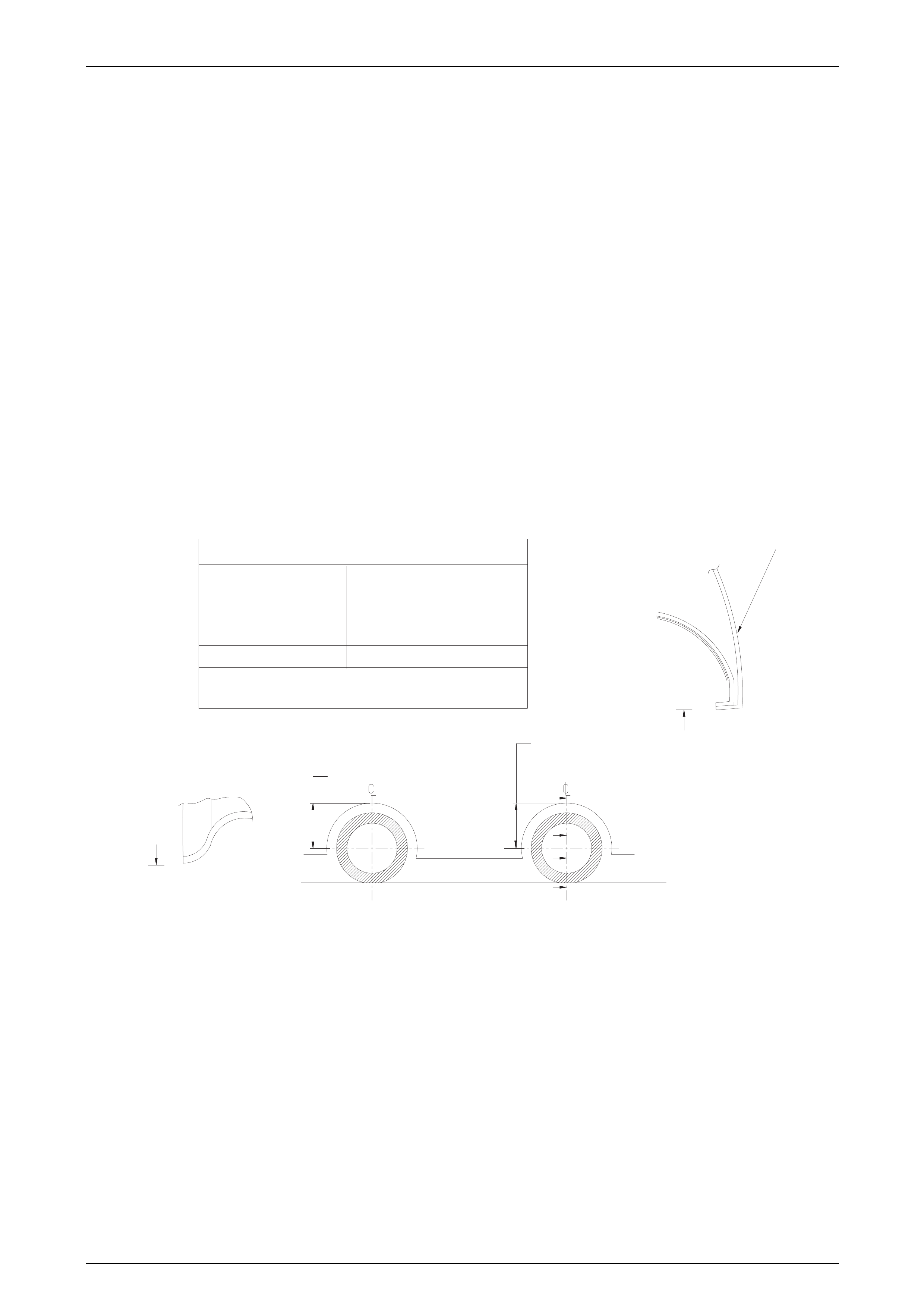
Front wheel camber alters as a function of front suspension height.
Camber adjusting bolt. After loosening both lower strut to steering knuckle bolts and nuts, adjust camber by turning bolt
clockwise to decrease negative camber a nd anti clockwise to increase neg ative camber. After adjustment, both lower
strut to steering knuckle bolts and nuts MUST be replaced with new parts and tightened to the recommended torque
setting.
The rear wheel alignment should be checked and corrected if necessary (refer to Section 4A, Rear Suspension, in the
MY 2004 VZ Service Information) before checking front wheel Alignment.
Fuel Mass with Full Tank..................................................................................................56kg
MEASURE SUSPENSION HEIGHTMEASURE SUSPENSION HEIGHT
FROM UNDERSIDE OF WHEEL ARCHFROM UNDERSIDE OF WHEEL ARCH
TO LOWER POINT OF WHEEL RIMTO LOWER POINT OF WHEEL RIM
B
B
A
A
SECTION A-A
SIDE PANEL OUTERSIDE PANEL OUTER
SECTION B-BSECTION B-B
MODEL VZ SEDAN
MODELS
VZ SEDAN
MODELS
VZ UTILITY
MODELS
VZ UTILITY
MODELS
WHEEL SIZE
FRONT
REAR
VEHICLE SUSPENSION HEIGHT AT KERB WEIGHTVEHICLE SUSPENSION HEIGHT AT KERB WEIGHT
Suspension Height Measurements in mm.Suspension Height Measurements in mm.
Kerb weight = Base weight + full tank of fuelKerb weight = Base weight + full tank of fuel
380±5380 ± 5 374±5374 ± 5
378±5378 ± 5 390±5390 ± 5
19"X8"19" X 8" 19"X8"19" X 8"
FRONT SUSPENSION HEIGHTFRONT SUSPENSION HEIGHT
REAR SUPSPENSION HEIGHTREAR SUPSPENSION HEIGHT
Suspension Page C-29
Page C-29
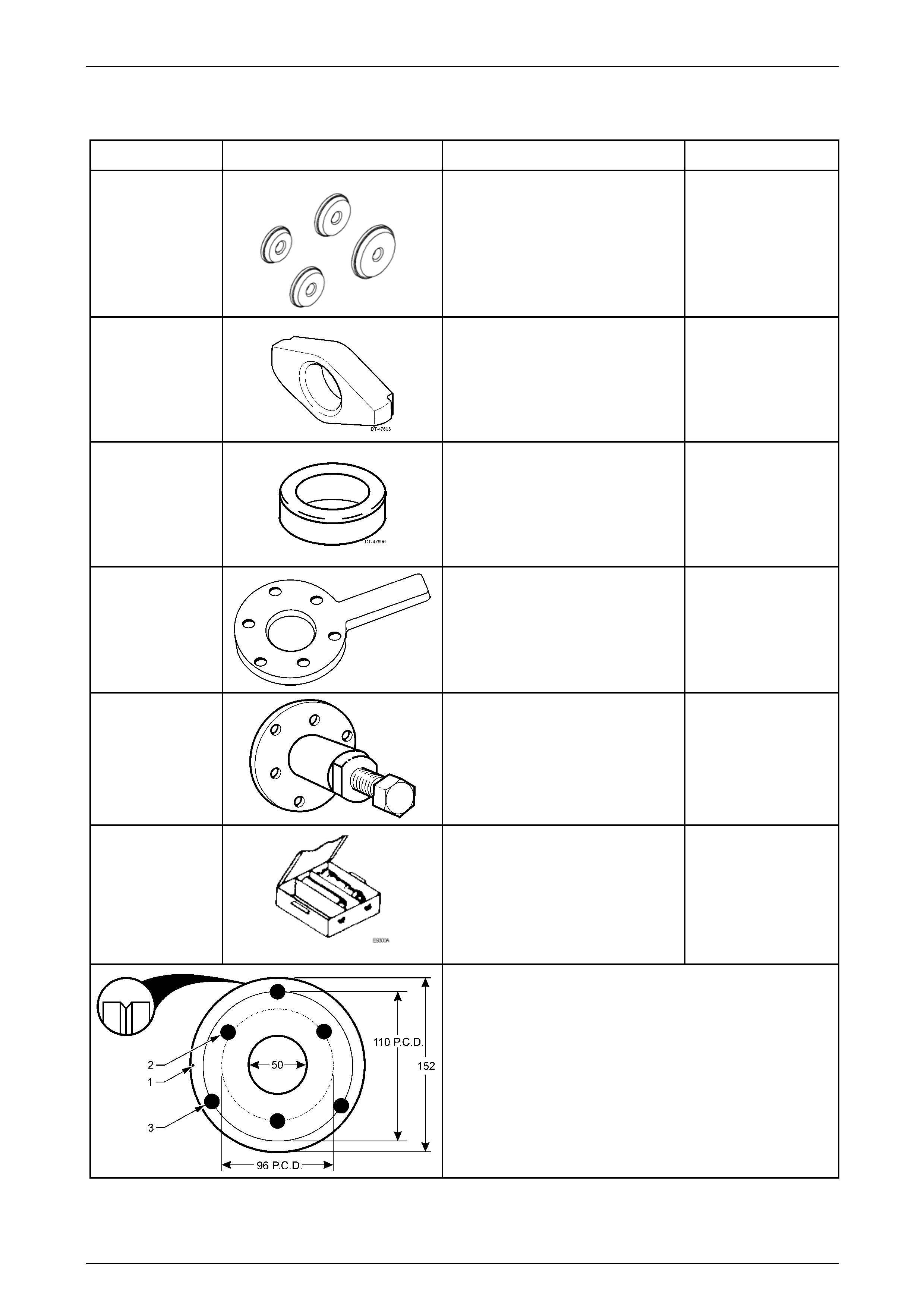
7 Special Tools
Tool Number Illustration Description Classification
205-552
Pinion Bearing Cup Ad aptors
Used to install the pinion bear ing
cups, in conjunction with R emover/
Installer E9271.
Previously released.
Unique
DT-47695
Rear Pinion Bearing Cup Remove r
Used in conjunction with remover
E9293 to remove the rear (inner)
pinion bearing cup.
DT-47696
Spacer
Used in conjunction with the dumm y
pinion from DT-47737 when checking
pinion position. Included in pinion
height setting gauge, DT-47737.
Previously released.
Unique
DT-47735
Holding Tool
Used to hold the final drive pin ion
flange when loosening/ti ghtening the
pinion nut. New release
Unique
DT-47736
Extractor Tool
Used to remove the final drive pinion
flange.
New release.
Unique
DT-47737
Pinion Height Setting Gauge
Includes dummy pinion, 3C10E/11,
Pad, 3C10E/13, Sleeve, 3C10E/14,
Dummy Pinion Spacer DT -47696,
Forcing Nut, 6651/13 and Arbour
AU408. New Assembly.
Unique
Pinion Flange Pulley
Fabricated from a 13 mm thick piece of wood or mild steel.
1 Form a 90° groove around the perimeter, 1.5 mm deep.
2 Drill a small hole (1) and attach a one metre length of thin
twine at this point.
3 Drill two sets of three, 13 mm holes on a pitch circle
diameter of 96 mm (2) and 110 mm (3), 120° apart, as
shown.