
Wheels, Tyres And Steering Wheel Page H-1
Page H-1
Section H
Wheels, Tyres And Steering Wheel
ATTENTION
HSV vehicles are equipped with a Supplemental Restraint System (SRS). An SRS consists of seat belt pre-
tensioners (fitted to all front seats), a d river’s-side air bag, a passeng er’s-side air bag and left and right h and
side air bags. Refer to CAUTIONS, Section 12M Occupant Protection System in th e MY 2005 VZ Series Ser vice
Information before performing any service operation on or around SRS components, the steering mechanism
or wiring. Failure to follow the CAUTIONS could result in personal injury or unnecessary SRS system repairs.
1 Purpose...................................................................................................................................................2
2 Wheels And Tyres ..................................................................................................................................3
2.1 General Description............................................................................................................................................... 3
2.2 Service Operations................................................................................................................................................ 4
2.3 Wheel and Tyre Balancing .................................................................................................................................... 5
2.4 HSV Wheel and Tyre Combinations..................................................................................................................... 6
VZ Wheel And Tyre Matrix..................................................................................................................................... 6
2.5 Tyre Placard And Pressures............................................................................................................................... 12
2.6 Loading The HSV Maloo...................................................................................................................................... 13
3 Steering Wheel......................................................................................................................................14
Techline
Wheels, Tyres And Steering Wheel Page H-2
Page H-2
1 Purpose
The purpose of this section is to provide information on the wheels, tyres and steering wheels fitted to the HSV VZ
models. The information is designed to supplement that given in the Holden VZ series Service Manual and details are
given where differences occu r between the HSV models and sta ndard Holden models. A series of ins truction drawings
describe the design changes and indicate specific part numbers, fitting instructions and relevant notes for vehicle
servicing.
NOTE
If specific technical data on a HSV model is not
contained in this supplement, obtain data for that
model from the relevant Holden VZ series Manua l
Supplement. References are made throughout
this section to Holden Service Manuals, to assist
in providing information for specific service
operations.
When hoisting (or jacking) HSV models,
ensure that the lifting h ead o f th e hoist lifts on
the chassis before the arm of the hoist
contacts the side-skirt
Wheels, Tyres And Steering Wheel Page H-3
Page H-3
2 Wheels And Tyres
2.1 General Description
HSV VZ models are fitted with alloy wheels develop ed specificall y for each HSV application. S everal types and sizes of
wheel are manufactured to suit the various applications and each wheel is manufactured from a single-piece alloy
casting.
NOTE
Specific wheel nuts are used to attach alloy
wheels to the vehicle. These nuts are fitted with
a plastic dress cap which must be removed prior
to undoing the wheel nuts.
HSV VZ wheels do no t have a steel insert and
therefore require wheel nuts with a flanged
seat as per the VT, VT2 and VX wheel nuts,
10B-970304. Do not use VS wheels nuts on
HSV VZ wheels.

Wheels, Tyres And Steering Wheel Page H-4
Page H-4
2.2 Service Operations
Alloy wheels fitted to all HSV vehicles are to be serviced in accordance with the procedures detailed in the relevant
Holden Service Manual, refer to Section 10 Wheels And Tyres. In addition, particular care should be taken with the
surface finish of alloy wheels. The manufacturer recommends that alloy surfaces be treated the same as high-gloss
painted services to prevent corrosion and genera l deteriorat ion.

Wheels, Tyres And Steering Wheel Page H-5
Page H-5
2.3 Wheel and Tyre Balancing
In order to balance the HSV Design wheels and t yre assemblies, refer to the relevant Hol den series Service Information,
refer to Section 10 Wheels And Tyres of the VZ Series Service Information.
NOTE
HSV wheels are balanced with concealed
weights. The lateral distance between these
weights is considerabl y less than the actua l width
of the wheel. To achieve wheel balance within
specification with concealed balance weights, set
the balancing machine for a wheel width of 5.5".

Wheels, Tyres And Steering Wheel Page H-6
Page H-6
2.4 HSV Wheel and Tyre Combinations
The following HSV Wheels and t yre combination are fitted to VZ.
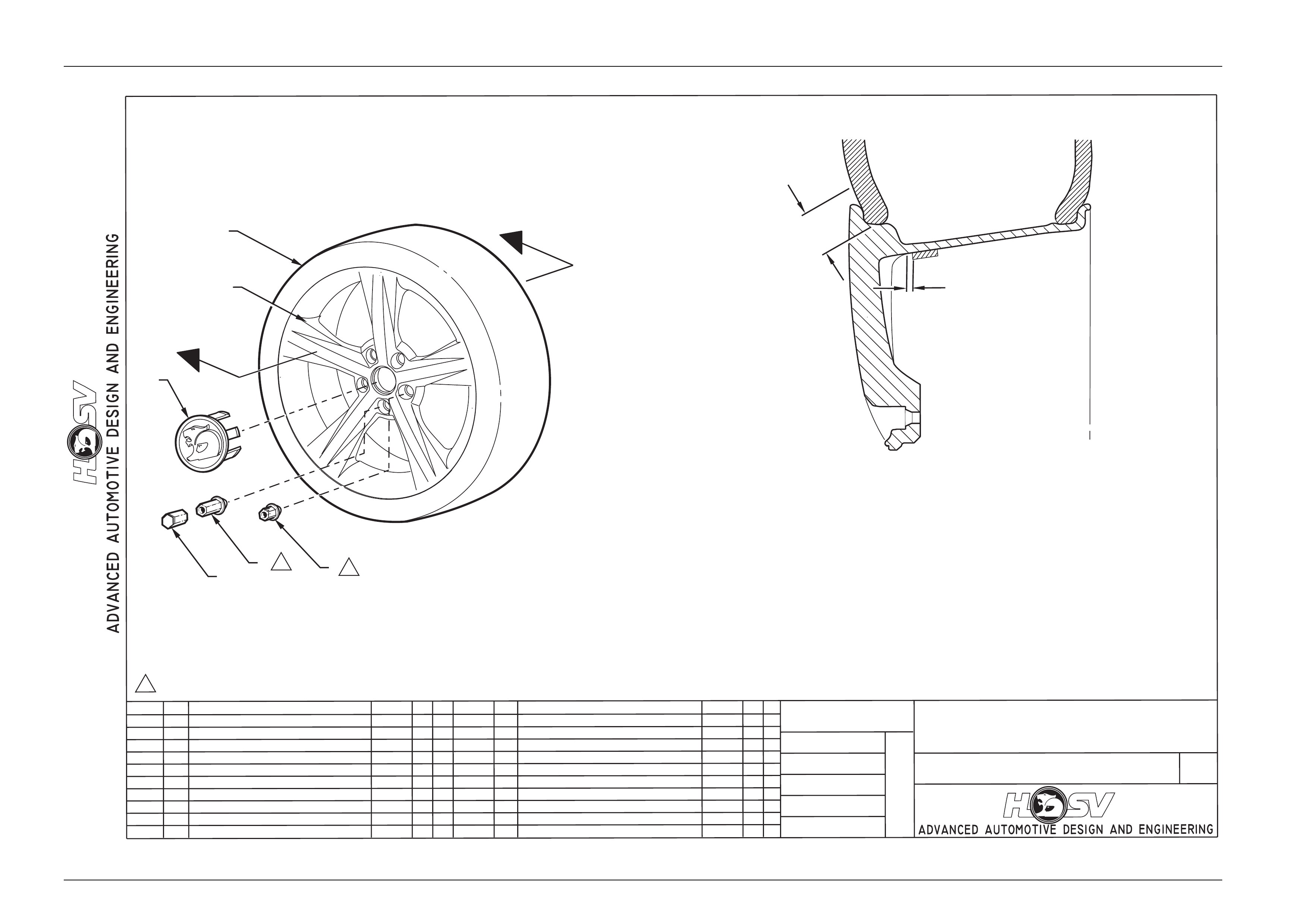
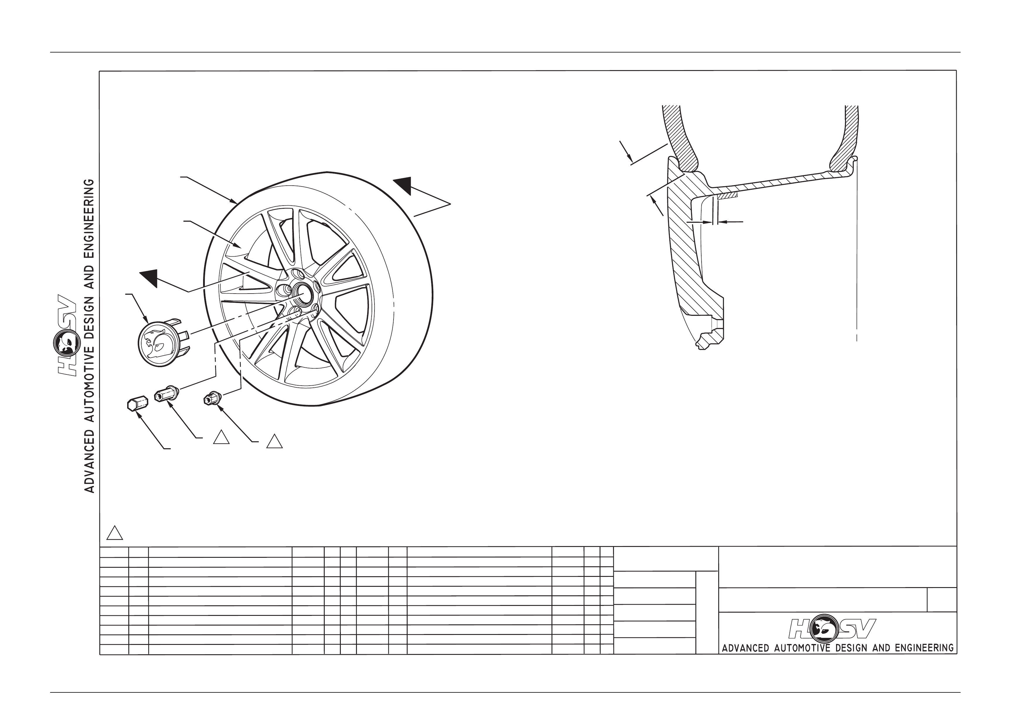
Refer to drawings 10I-020012 (Clubsport & Malo o), 10I-020010 (Clubsport R8, Maloo R8 & Coupe),
10I-020011 (Senator & Grange), 10I-020005 (Senator 19”) and 10I-020013 (Spare Wheel All Models).
VZ Wheel And Tyre Matrix
WHEEL TYRE
MODEL 10B-040601-B 10B-040602-C 10B-040801- C 10B-020804 245/35 ZR19 235/35 ZR19
VZ CLUBSPORT S
S
Before Aug
2005
S
After Aug 2005
VZ CLUBSPORT R8 S
S
Before Aug
2005
S
After Aug 2005
VZ MALOO S S
VZ MALOO R8 S S
VZ SENATOR S O S
Wheels, Tyres And Steering Wheel Page H-7
Page H-7
DATE
ISSUE DATED
AUTH'Y
CK.
SYM
AUTH'Y
REVISION RECORD
DATE
SYM
SIGNATURES ON
ORIGINAL APPROVAL
DR.
10I-020012
INSTRUCTION DRAWING.
A4
SIZE
ALLOY WHEEL
VZ CLUBSPORT&MALOO
REVISION RECORD
PRELIMINARY ISSUE
CK.
NAME
PART NO.
CK.
REFERENCE
DWG.
DR.
DATE:
APPR
APPR
DR.
22/11/04
AP
DP
NOTE: BREAKAWAYTORQUE
OF WHEEL NUTS TOBE
100 Nm MINIMUM
100-125 Nm
1. 10B-101919 CAP WHEEL NUT 5 PLACES
2. 10B-970219 FRONT & REAR WHEEL NUT
3. 10B-030301 CAP & BADGE ASM WHEEL
4. 10B-040601-B WHEEL ALLOY
5. FRONT AND REAR TYRE 245/35 R19 93Y (PRE AUG 2005) OR 235/35 R19 93Y (POST AUG 2005)
6. LOCKNUTS SPZ-300168
A
A
16
3
4
5
2
A. LUBRICATE TYRE BEADS BOTH SIDES FULL CIRCUMFERANCE WITH TYRE
MOUNTING LUBRICANT IN ACCORDANCE WITH HN - 1162. TYRE INSTALLATION
MUST BE MADE BEFORE LUBRICANT IS DRYTO ENSURE SATISFACTORYBEAD
SEATING,TYRE IS TO BE INFLATED TO 280kPa ON INITIAL ASSEMBLY
.
B. POSITION STICK-ON WHEEL WEIGHT AS CLOSE AS POSSIBLE TO SPOKE EDGE
(MAXIMUM 5mm) AND ENSURE SUFFICIENT CLEARANCE BETWEEN THE WHEEL
WEIGHT AND BRAKE CALIPER EXISTS.
SEC A-A
NOTES :
1
1
1
A
B
Wheels, Tyres And Steering Wheel Page H-8
Page H-8
DATE
ISSUE DATED
AUTH'Y
CK.
SYM
AUTH'Y
REVISION RECORD
DATE
SYM
SIGNATURES ON
ORIGINAL APPROVAL
DR.
10I-020010
INSTRUCTION DRAWING.
A4
SIZE
ALLOY WHEEL
VZ CLUBSPORTR8, MALOO R8, COUPE
REVISION RECORD
PRELIMINARY ISSUE
CK.
NAME
PART NO.
CK.
REFERENCE
DWG.
DR.
DATE:
APPR
APPR
DR.
20/10/04
AP
DP
NOTE: BREAKAWAYTORQUE
OF WHEEL NUTS TOBE
100 Nm MINIMUM
100-125 Nm
1. 10B-101919 CAP WHEEL NUT 5 PLACES
2. 10B-970219 FRONT & REAR WHEEL NUT
3. 10B-030301 CAP & BADGE ASM WHEEL
4. 10B-040602-C WHEEL ALLOY
5. FRONT AND REAR TYRE 245/35 R19 93Y (PRE AUG 2005) OR 235/35 R19 93Y (POST AUG 2005)
6. LOCKNUTS SPZ-300168
A
A
16
3
4
5
2
A. LUBRICATE TYRE BEADS BOTH SIDES FULL CIRCUMFERANCE WITH TYRE
MOUNTING LUBRICANT IN ACCORDANCE WITH HN - 1162. TYRE INSTALLATION
MUST BE MADE BEFORE LUBRICANT IS DRYTO ENSURE SATISFACTORYBEAD
SEATING,TYRE IS TO BE INFLATED TO 280kPa ON INITIAL ASSEMBLY
.
B. POSITION STICK-ON WHEEL WEIGHT AS CLOSE AS POSSIBLE TO SPOKE EDGE
(MAXIMUM 5mm) AND ENSURE SUFFICIENT CLEARANCE BETWEEN THE WHEEL
WEIGHT AND BRAKE CALIPER EXISTS.
SEC A-A
NOTES :
1
1
1
A
B
Wheels, Tyres And Steering Wheel Page H-9
Page H-9
DATE
ISSUE DATED
AUTH'Y
CK.
SYM
AUTH'Y
REVISION RECORD
DATE
SYM
SIGNATURES ON
ORIGINAL APPROVAL
DR.
10I-020011
INSTRUCTION DRAWING.
A4
SIZE
ALLOY WHEEL
WL GRANGE / VZ SENATOR
REVISION RECORD
PRELIMINARY ISSUE
CK.
NAME
PART NO.
CK.
REFERENCE
DWG.
DR.
DATE:
APPR
APPR
DR.
18/11/04
AP
DP
NOTE: BREAKAWAYTORQUE
OF WHEEL NUTS TOBE
100 Nm MINIMUM
100-125 Nm
1. 10B-101919 CAP WHEEL NUT 5 PLACES
2. 10B-970219 FRONT & REAR WHEEL NUT
3. 10B-030301 CAP & BADGE ASM WHEEL
4. 10B-040801-C WHEEL ALLOY
5. FRONT AND REAR TYRE 245/35 R19 93Y
6. LOCKNUTS SPZ-300168
A
A
16
3
4
5
2
A. LUBRICATE TYRE BEADS BOTH SIDES FULL CIRCUMFERANCE WITH TYRE
MOUNTING LUBRICANT IN ACCORDANCE WITH HN - 1162. TYRE INSTALLATION
MUST BE MADE BEFORE LUBRICANT IS DRYTO ENSURE SATISFACTORYBEAD
SEATING,TYRE IS TO BE INFLATED TO 280kPa ON INITIAL ASSEMBLY
.
B. POSITION STICK-ON WHEEL WEIGHT AS CLOSE AS POSSIBLE TO SPOKE EDGE
(MAXIMUM 5mm) AND ENSURE SUFFICIENT CLEARANCE BETWEEN THE WHEEL
WEIGHT AND BRAKE CALIPER EXISTS.
SEC A-A
NOTES :
1
1
1
A
B
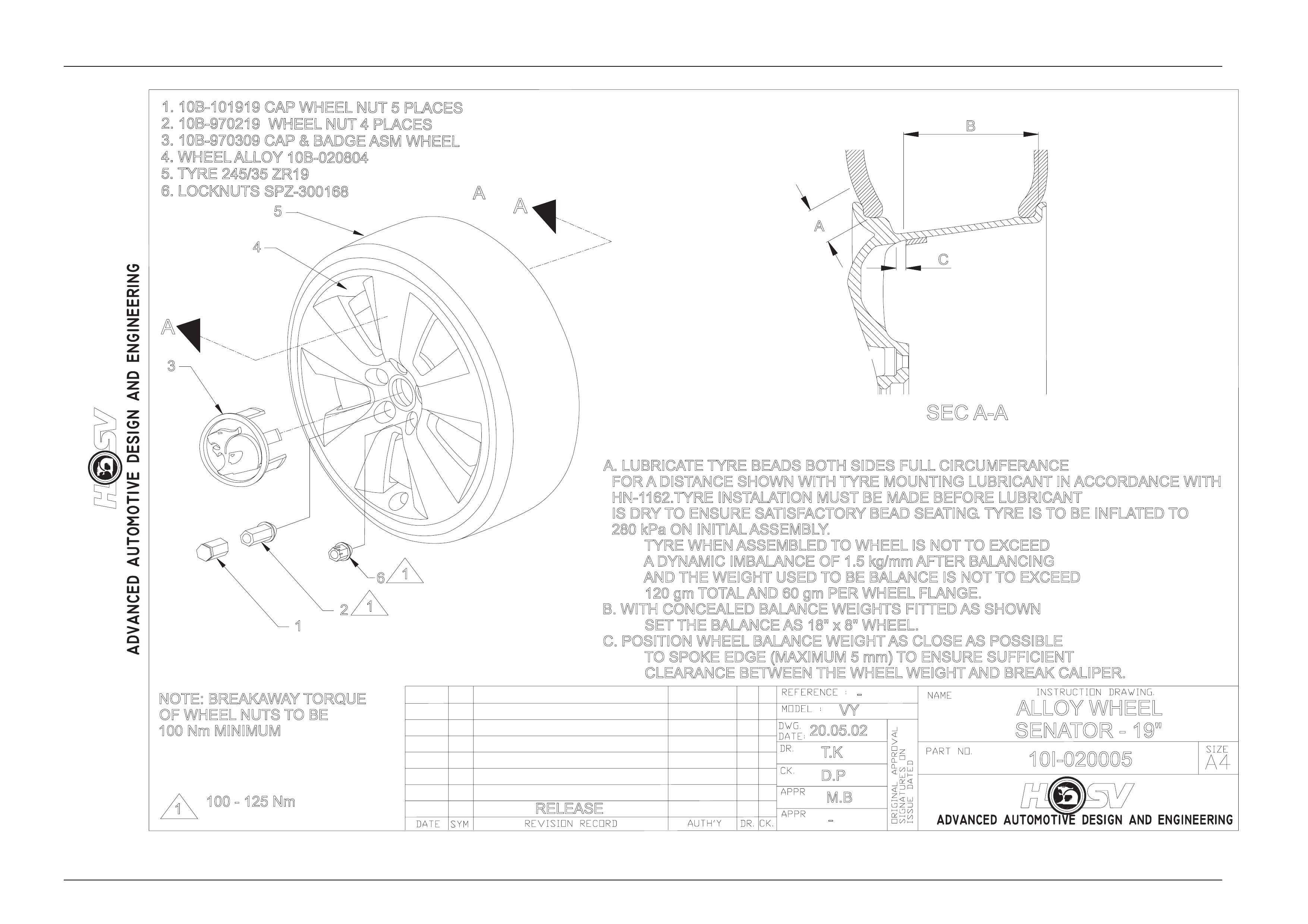
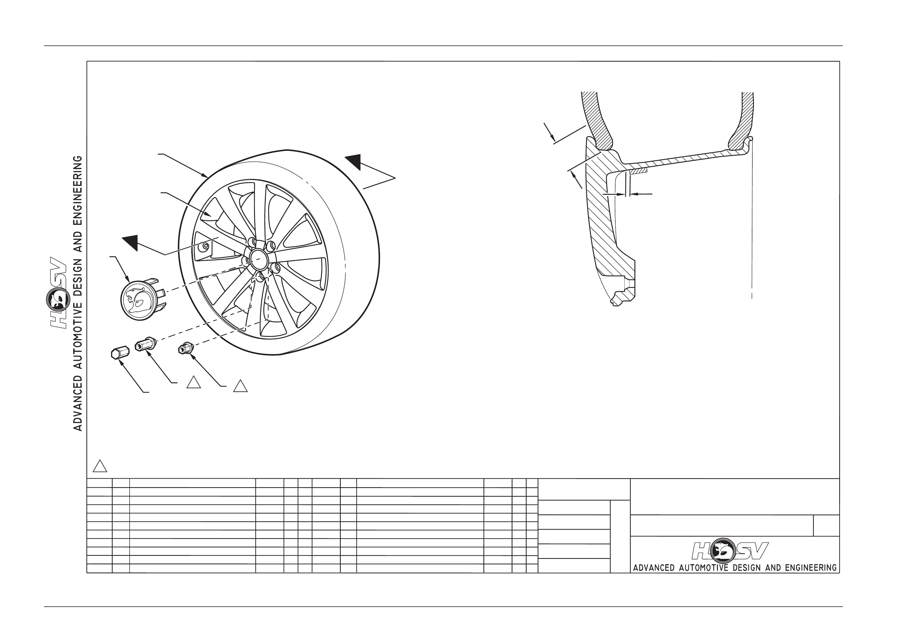
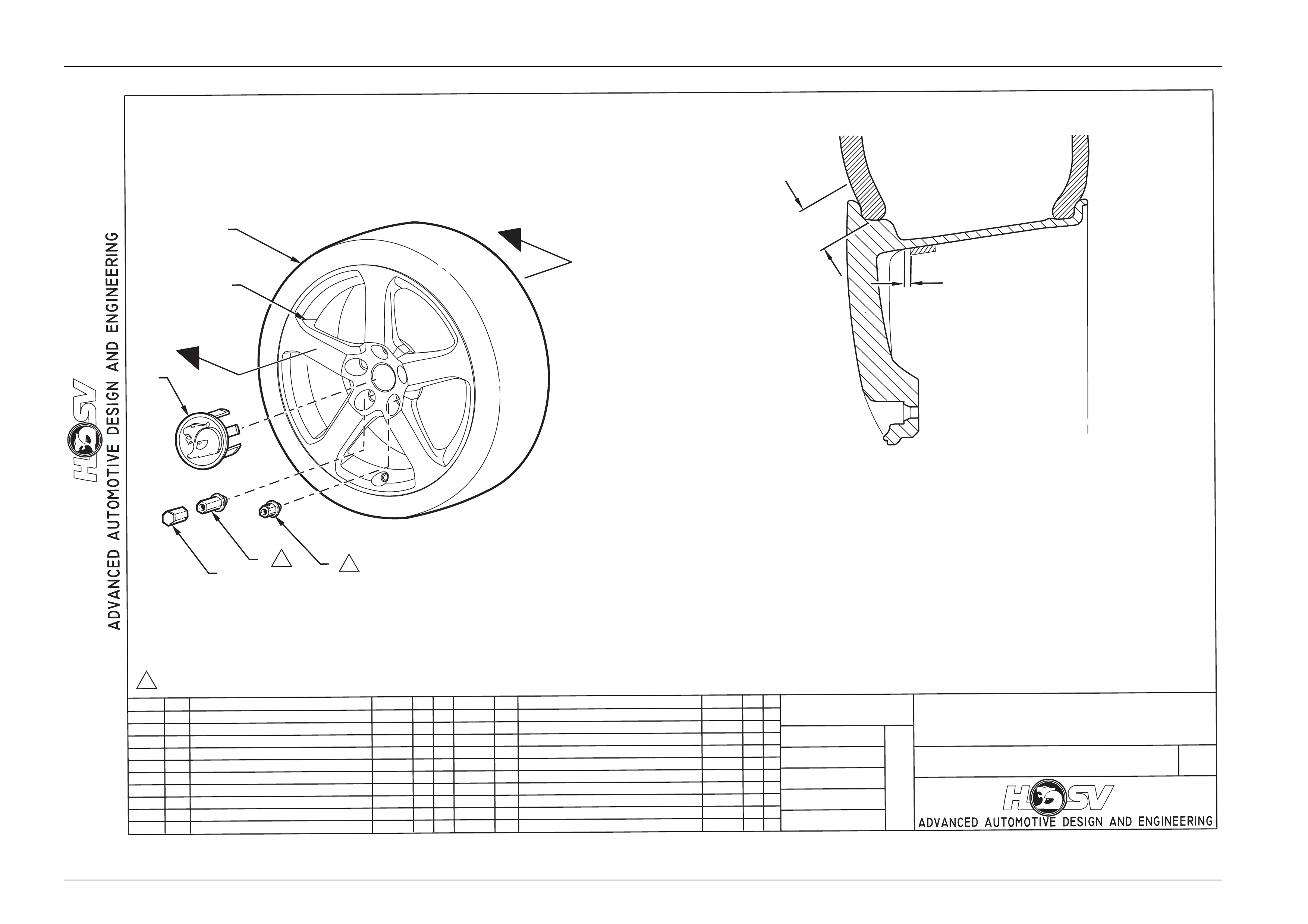
Wheels, Tyres And Steering Wheel Page H-10
Page H-10
100 - 125 Nm
NOTE: BREAKAWAY TORQUE
OF WHEEL NUTS TO BE
100 Nm MINIMUM
SEC A-A
RELEASE
1M.B
VY
T.K
D.P
20.05.02
10I-020005
-ALLOY WHEEL
SENATOR - 19"
-
A. LUBRICATE TYRE BEADS BOTH SIDES FULL CIRCUMFERANCE
FOR A DISTANCE SHOWN WITH TYRE MOUNTING LUBRICANT IN ACCORDANCE WITH
HN-1162.TYRE INSTALATION MUST BE MADE BEFORE LUBRICANT
IS DRY TO ENSURE SATISFACTORY BEAD SEATING. TYRE IS TO BE INFLATED TO
280 kPa ON INITIAL ASSEMBLY.
TYRE WHEN ASSEMBLED TO WHEEL IS NOT TO EXCEED
A DYNAMIC IMBALANCE OF 1.5 kg/mm AFTER BALANCING
AND THE WEIGHT USED TO BE BALANCE IS NOT TO EXCEED
120 gm TOTAL AND 60 gm PER WHEEL FLANGE.
B. WITH CONCEALED BALANCE WEIGHTS FITTED AS SHOWN
SET THE BALANCE AS 18" x 8" WHEEL.
C. POSITION WHEEL BALANCE WEIGHT AS CLOSE AS POSSIBLE
TO SPOKE EDGE (MAXIMUM 5 mm) TO ENSURE SUFFICIENT
CLEARANCE BETWEEN THE WHEEL WEIGHT AND BREAK CALIPER.
2
6
1
1
3
4
5
A
A
B
A
C
1
1. 10B-101919 CAP WHEEL NUT 5 PLACES
2. 10B-970219 WHEEL NUT 4 PLACES
3. 10B-970309 CAP & BADGEASM WHEEL
4. WHEEL ALLOY10B-020804
5. TYRE 245/35 ZR19
6. LOCKNUTS SPZ-300168
A
Wheels, Tyres And Steering Wheel Page H-11
Page H-11
DATE
ISSUEDATED
AUTH'Y
CK.
SYM
AUTH'Y
REVISION RECORD
DATE
SYM
SIGNATURESO
N
ORIGINAL APPROVAL
DR.
10I-020013
INSTRUCTION DRAWING.
A4
SIZE
ALLOY WHEEL(SPARE)
VZ SEDANS, MALOO & WL GRANGE
REVISION RECORD
PRELIMINARY ISSUE
CK.
NAME
PART NO.
CK.
REFERENCE
DWG.
DR.
DATE:
APPR
APPR
DR.
25/11/04
AP
DP
NOTE: BREAKAWAYTORQUE
OFW
HEEL NUTS TOBE
100 Nm MINIMUM
100-125 Nm
1. 10B-101919 CAP WHEEL NUT 5 PLACES
2. 10B-970219 FRONT & REAR WHEEL NUT
3. 10B-030301 CAP & BADGEASM WHEEL
4. 10B-020601-D WHEEL ALLOY
5. FRONT AND REAR TYRE 215/45 R18 93W
6. LOCKNUTS SPZ-300168
A
A
16
3
4
5
2
A. LUBRICATE TYRE BEADS BOTH SIDES FULL CIRCUMFERANCE WITH TYRE
MOUNTING LUBRICANT IN ACCORDANCE WITH HN - 1162. TYRE INSTALLATION
MUST BE MADE BEFORE LUBRICANT IS DRYTO ENSURE SATISFACTORYBEAD
SEATING,TYRE IS TO BE INFLATED TO 280kPa ON INITIAL ASSEMBLY
.
B. POSITION STICK-ON WHEEL WEIGHT AS CLOSE AS POSSIBLE TO SPOKE EDGE
(MAXIMUM 5mm) AND ENSURE SUFFICIENT CLEARANCE BETWEEN THE WHEEL
WEIGHT AND BRAKE CALIPER EXISTS.
SECA-A
NOTES:
1
1
1
A
B

Wheels, Tyres And Steering Wheel Page H-12
Page H-12
2.5 Tyre Placard And Pressures
The HSV Tyre Placard is posit ioned on the opening of the right han d door. The Tyre Placard details imp ortant
information on the tyre pressures recomme nded for the HSV VZ Series Models. If carrying load, or travelling at high
speed, the tyre pressures need to be increased as detailed on the placar d. T his is very important for tyre wear and also
to ensure that the tyres have sufficient load carr ying capacity.

Wheels, Tyres And Steering Wheel Page H-13
Page H-13
2.6 Loading The HSV Maloo
Also on the right hand door opening are the HSV Maloo pa yload details. The Maloo is restricted to a maximum loading
of 570kg, with the driver and passenger in the car, this leaves approximately 430kg load capacity for the rear tray. As
noted above, it is important to increase tyre pressures when vehicle load is increased, refer to the tyre placard.

Wheels, Tyres And Steering Wheel Page H-14
Page H-14
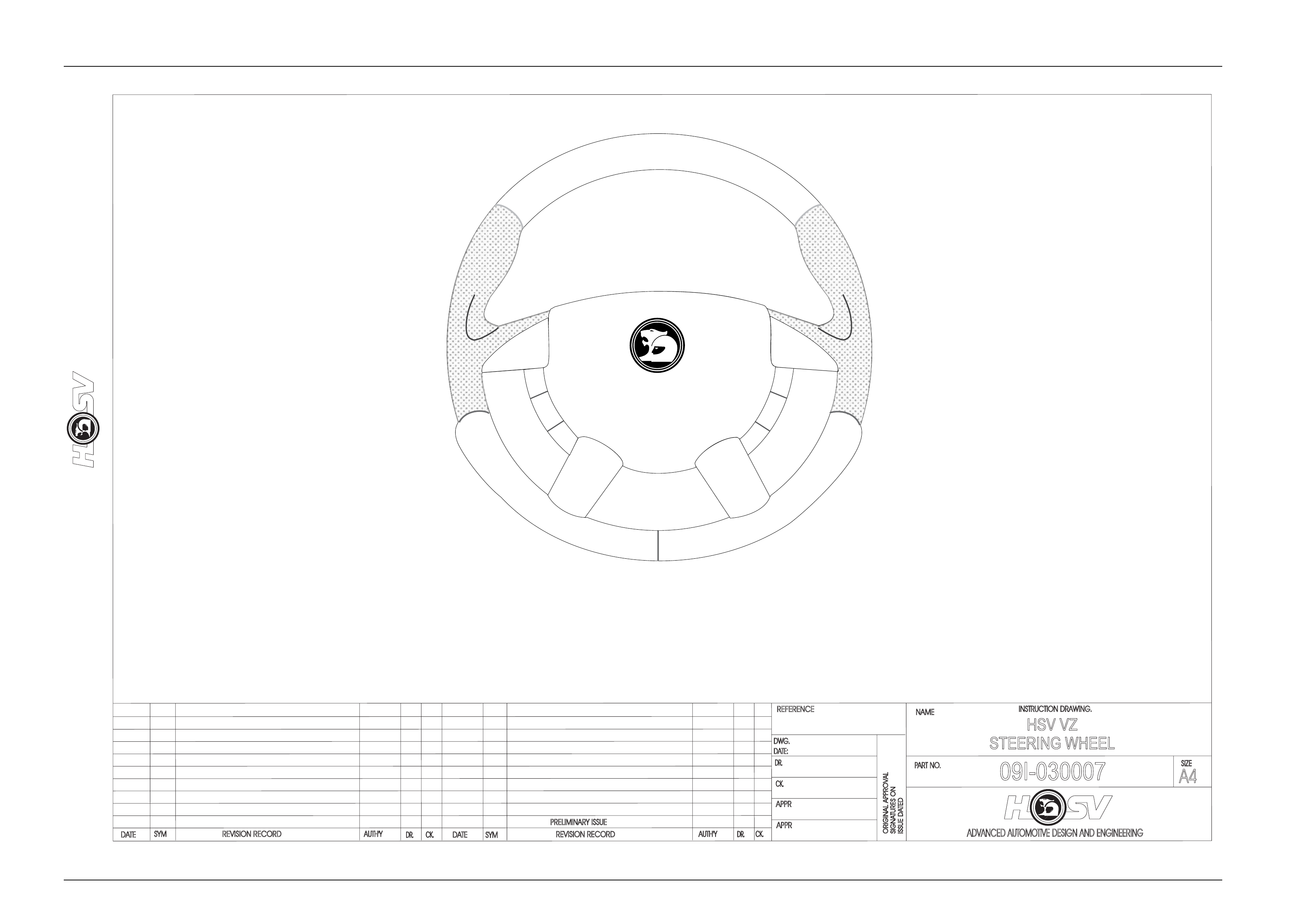
3 Steering Wheel
HSV VZ vehicles are equipped with AIR
BAGS. An AIR BAG is a Supplemental
Restraint System (SRS). Refer to CAUTIONS,
Section 12M, in Volume 12 of the Holden VZ
series Service Manual Supplement before
performing any service operation on or
around SRS components, the steering
mechanism or wiring. Failure to follow the
CAUTIONS could result in air bag
deployment, resulting in possible personal
injury or unnecessary SRS system repairs.
The steering wheel assembly fitted to all HSV VZ models incorporates a H SV-design central horn pad complete with
HSV logo (see Drawing 09I-030001). The central horn pad also incorporates the driver’s-side air bag. All other
components, fixtures and fasteners are identical to standard Holden parts and therefore, any service operations on the
assembly should be carried out in accord ance with the relevant Holden Service Manual Supplement,
refer to Section 9 Steering of the VZ Series Service Information.
Wheels, Tyres And Steering Wheel Page H-15
Page H-15
DATE
ISSUE DATED
AUTH'Y
CK.
SYM
AUTH'Y
REVISION RECORD
DATE
SYM
SIGNATURES ON
ORIGINAL APPROVAL
DR.
ADVANCED AUTOMOTIVE DESIGN AND ENGINEERING
09I-030007
INSTRUCTION DRAWING.
A4
SIZE
HSV VZ
STEERING WHEEL
REVISION RECORD
PRELIMINARY ISSUE
CK.
NAME
PART NO.
CK.
REFERENCE
DWG.
DR.
DATE:
APPR
APPR
DR.
22/03/05
AP
DP
GD
VZ STEERING WHEEL PART NUMBERS
CLUBSPORTAND MALOO - 92166653
CLUBSPORTR8 AND MALOO R8 - 92166653
SENATOR - 92166654