
Body Page B-1
Page B-1
Section B
Body
ATTENTION
HSV vehicles are equipped with a Supplemental Restraint System (SRS). An SRS consists of seat belt pre-
tensioners (fitted to all front seats), a dri ver’s-side air bag , a passenger’s-sid e air bag and left and right hand
side air bags. Refer to CAUTIONS, Section 12M, of the Holden WL Service Information before performing any
service operation on or around SRS components, the steering mechanism or wiring. Failure to follow the
CAUTIONS could result in personal injury or unnecessary SRS system repairs.
1 Purpose...................................................................................................................................................2
1.1 General Service Information................................................................................................................................. 2
2 Seats........................................................................................................................................................3
WL Seat Kits - Front And Rear.............................................................................................................................. 5
WL Trim Cover Assemblies Front And Rear........................................................................................................ 5
WL Frames - Front And Rear ................................................................................................................................ 5
WL Pads - Front And Rear..................................................................................................................................... 5
3 Body Components .................................................................................................................................6
3.1 WL Grange 297 LS2 Sedan ................................................................................................................................... 6
Service Operations................................................................................................................................................ 6
4 Rear Spoiler Service Procedure..........................................................................................................17
5 WL Rear Decklid Spoiler......................................................................................................................19
6 WL Radiator Grille................................................................................................................................20
Removal................................................................................................................................................................ 20
Assembly.............................................................................................................................................................. 20
7 WL Rear Décor Panel...........................................................................................................................23
Removal................................................................................................................................................................ 23
Assembly.............................................................................................................................................................. 23
8 WL Fender Vent Service Procedures .................................................................................................25
Removal................................................................................................................................................................ 25
Globe................................................................................................................................................................ 25
Vent.................................................................................................................................................................. 25
Installation............................................................................................................................................................ 25
Heat Staking Procedure ...................................................................................................................................... 27

Body Page B-2
Page B-2
1 Purpose
The purpose of this section is to provide information on the body and body components fitted to HSV WL vehicles. The
information is designed to supplement the information contained in the Holden WL Service Information, and details are
given where differences occur between the HSV models and standard Holden models. A series of instruction drawings
describe the design changes and indicate specific part numbers, fitting instructions and relevant notes for vehicle
servicing.
NOTE
If specific technical data on a HSV model is not
contained in this supplement, obtain data for that
model from the relevant Holden WL Service
Information Supplement. References are made
throughout this section to Holden Service
Information, to assist in providing information for
specific service operations.
When hoisting (or jacking) HSV models,
ensure that the lifting h ead o f th e hoist lifts on
the chassis before the arm of the hoist
contacts the side-skirt
1.1 General Service Information
For all body dimensions refer to Section 1A2 Body section of the Holden MY200 5 WL Series Models Service Information.
For all body components not unique to HSV refer to Section 1A2 Body section of the H olden MY2005 WL Series Models
Service Information.
The HSV WL Grange is equipped with unique Body Side Skirts, Front Bumper Facia, Rear Spoiler, Radiator Grille and
Rear Décor Panel.
It is recommended that before any body repa irs be undertaken that the components involved be carefully inspected to
gain a clear understanding as to their design.
This should include attachi ng methods, assembly margins, painted features and paint accents.
Inspect the components using the relev ant HSV service instruction drawings as reference.
Where practical digital photographs can taken as required prior to work commencing, these could b e of assistance a
latter date to be used during reassembl y.
Relevant attachment tightening torque values are shown on HSV service instruction drawings. The torque locations are
defined as a number in a triangle besi de the attachment, this relates to the torque value shown on the lower margin of
the drawing.
Typical example of torque symbol location 2
Body Page B-3
Page B-3
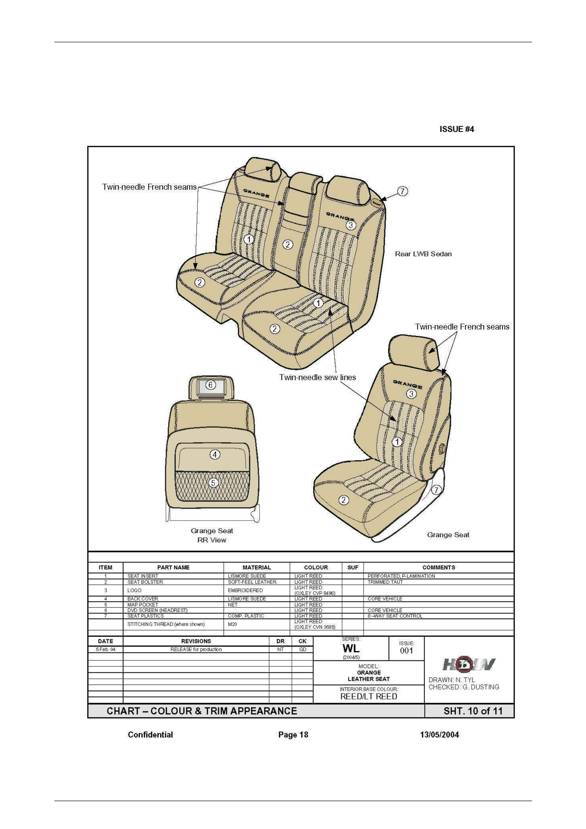
2 Seats
Figure B-1 – Chart Colour and Trim Appearance
Body Page B-4
Page B-4
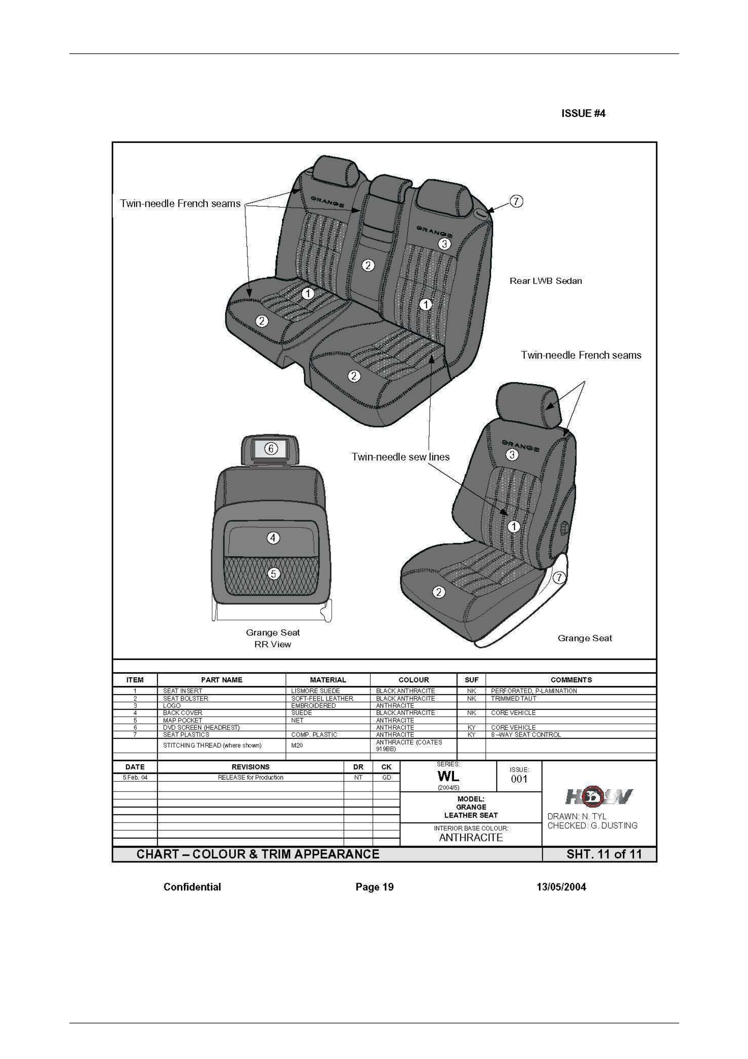
Figure B-2 – Chart Colour and Trim Appearance
Body Page B-5
Page B-5
WL Seat Kits - Front And Rear FS ASS.
RH FS ASS.
LH RSC
ASS. RSB
ASS.RH RSB
ASS.LH RSB
FLAP
ASS.
1 92176470 / 41 06470 WL GRANGE LEATHER NK 4102198 4102199 4102200 4102202 4102201 4102203
2 92176469 / 41 06469 WL GRANGE LEATHER LR 4102204 4102205 4102206 4102208 4102207 4102209
WL Trim Cover
Assemblies Front And
Rear
T CVR FSC T CVR FSB
RH T CVR FSB
LH T CVR FRT
H/REST T CVR RSC T CVR RSB
RH T CVR RSB
LH T CVR
FLAP T CVR
REAR
H/REST
T CVR
REAR ARM
REST
T CVR
FLAP
H/REST
1 92176470 /
4106470 WL GRANGE
LEATHER NK 4102157NK 4102158NK 4102159NK 4102160NK 4102161NK 4102162NK 4102163NK 4102164NK 4102165NK 4102166NK 4102141NK
2 92176469 /
4106469 WL GRANGE
LEATHER LR 4102157LR 4102158LR 4102159LR 4102160LR 4102161LR 4102162LR 4102163LR 4102164LR 4102165LR 4102166LR 4102141LR
WL Frames - Front And Rear FSC
FRAME
ASM.
FSB
FRAME
ASM RH
FSB
FRAME
ASM L H
RSC
FRAME
ASM.
RSB
FLAP
FRAME
ASM.
REAR
ARMRE
ST ASM.
92176470 / 4106470 WL GRANGE LEATHER NK 4003600 4005733 4005731 4004136 4002085 4004138
92176469 / 4106469 WL GRANGE LEATHER LR 4003600 4005733 4005731 4004136 4002085 4004138
WL Pads - Front And Rear FSC
PAD FSB
PAD FRT
H/REST
PAD
ASS.
RSC
PAD RSB
PAD
ASS.
RH
RSB
PAD
ASS. LH
RSB
FLAP
PAD
REAR
H/REST
PAD
ASS.
REAR
ARMRE
ST PAD
ASS.
FLAP
H/REST
PAD
ASS.
1 92176470
/ 4106470 WL GRANGE
LEATHER NK 4004149 4004146 4004120 4004161 4001874 4001875 4005253 4002172 4004427 4001884
2 92176469
/ 4106469 WL GRANGE
LEATHER LR 4004149 4004146 4004120 4004161 4001874 4001875 4005253 4002172 4004427 4001884

Body Page B-6
Page B-6
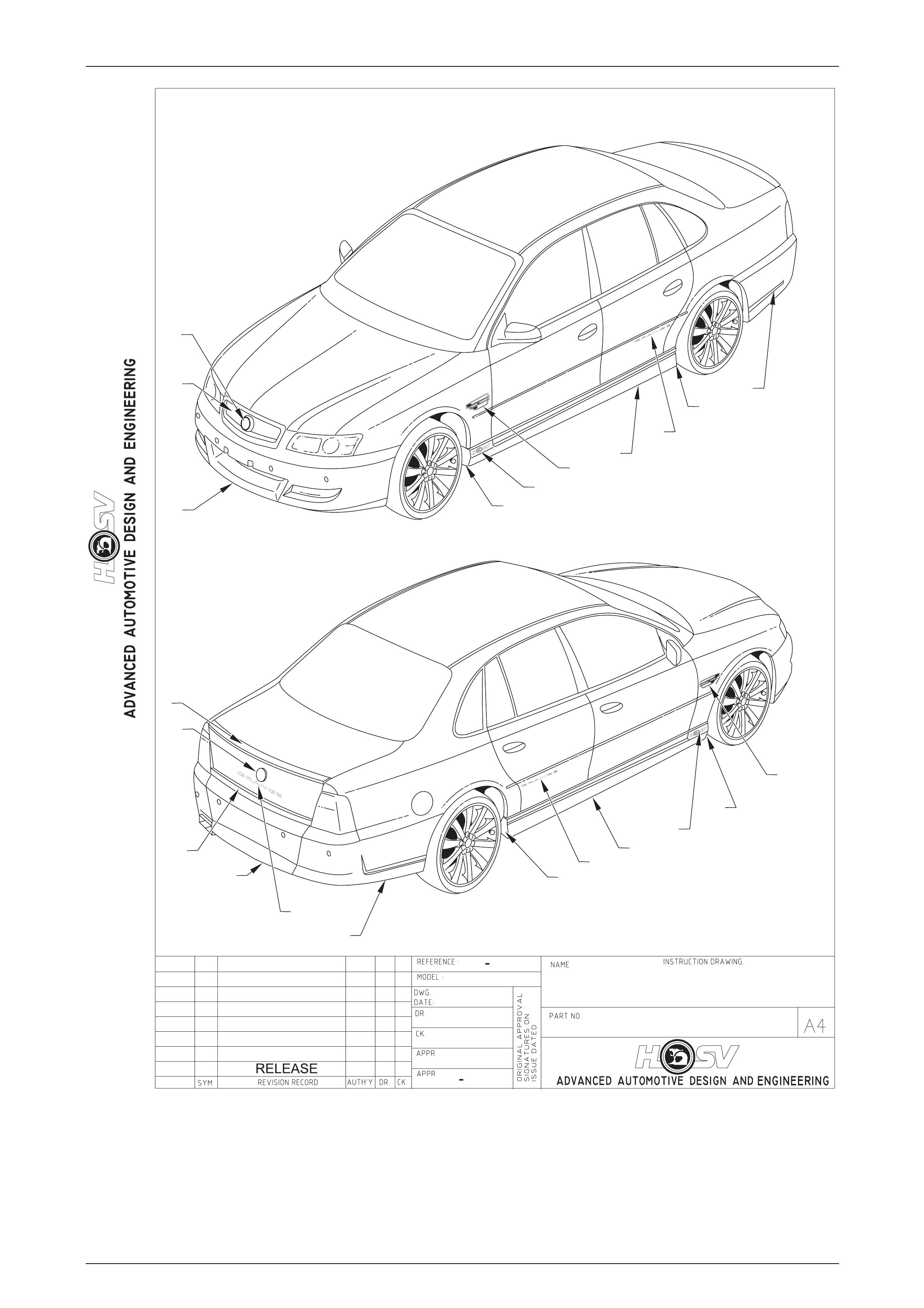
3 Body Components
3.1 WL Grange 297 LS2 Sedan
CONTENTS OF BODY STYLING PACKAGE
PART No QTY DESCRIPTIONS REF
A08-031304 1 SIDE SKIRT – ASSEMBLY – RH 1
A08-031303 1 SIDE SKIRT – ASSEMBLY – LH 2
14A2031307 1 REAR FACIA – CENTRE 3
14A2031305 1 REAR FACIA – LH 4
14A2031306 1 REAR FACIA – RH 5
E08-031301 1 SPOILER – REAR 6
E08-031305 1 PANEL REAR DECOR 7
A08-020604 1 PAINT PROTECTOR-SIDE SKIRT FRT RH 8
A08-020603 1 PAINT PROTECTOR-SIDE SKIRT-FRT LH 9
A08-020606 1 PAINT PROTECTOR-SIDE SKIRT-RR RH 10
A08-020605 1 PAINT PROTECTOR-SIDE SKIRT-RR LH 11
E08-031310B8 1 BADGE – GRANGE LH 12
E08-031310B8 1 BADGE – GRANGE RH 13
E08-031303B8 1 BADGE – GRANGE – REAR 14
E08-031307 2 BADGE – LION & HELMET 15
A08-040601B8 1 BADGE – CORPORATE LOGO – LH 16
A08-040601B8 1 BADGE – CORPORATE LOGO – RH 17
13C-031310 1 GRILLE RADIATOR ASSEMBLY 18
14A-1031301 1 FRONT FACIA 19
HSV-B08040810P 1 FENDER VENT RH 20
HSV-B08040809P 1 FENDER VENT LH 21
Service Operations
When servicing the WL Grange 297 Sed an Body Components, refer to the following drawings.
Body Page B-7
Page B-7
BODY - ORNAMENTATION
WL GRANGE
15.11.04
AP
D.P
D.P
1A2F040054
1
2
3
4
5
6
7
8
9
10
12
13
19
16
17
11
14
15
15
18
20
21
Body Page B-8
Page B-8
ADVANCED AUTOMOTIVE DESIGN AND ENGINEERING
INSTRUCTION DRAWING.
A4
SIZE
REVISION RECORD
PRELIMINARY ISSUE
CK.
NAME
PART NO.
CK.
REFERENCE
DWG.
DR.
DATE:
APPR
APPR
DR.
AUTH'Y
REVISION RECORD
AUTH'Y
SYM
DATE
DR.CK.
DATE
SYM
ORIGINAL APPROVAL
SIGNATURES ON
ISSUE DATED
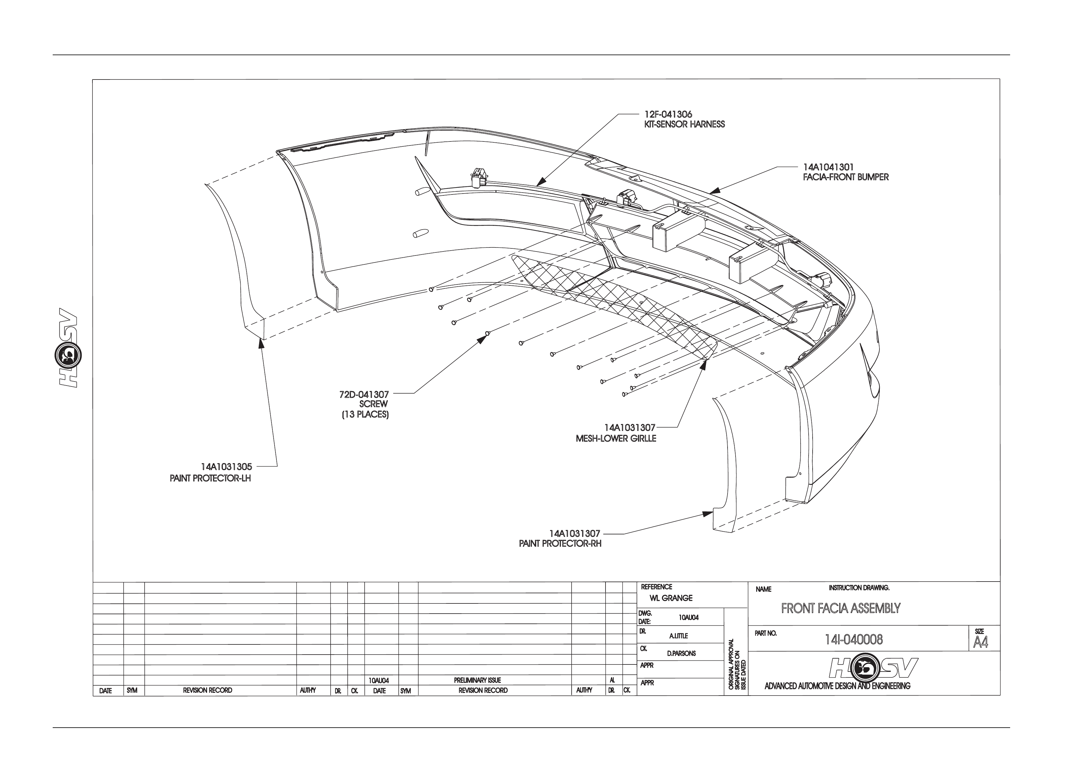
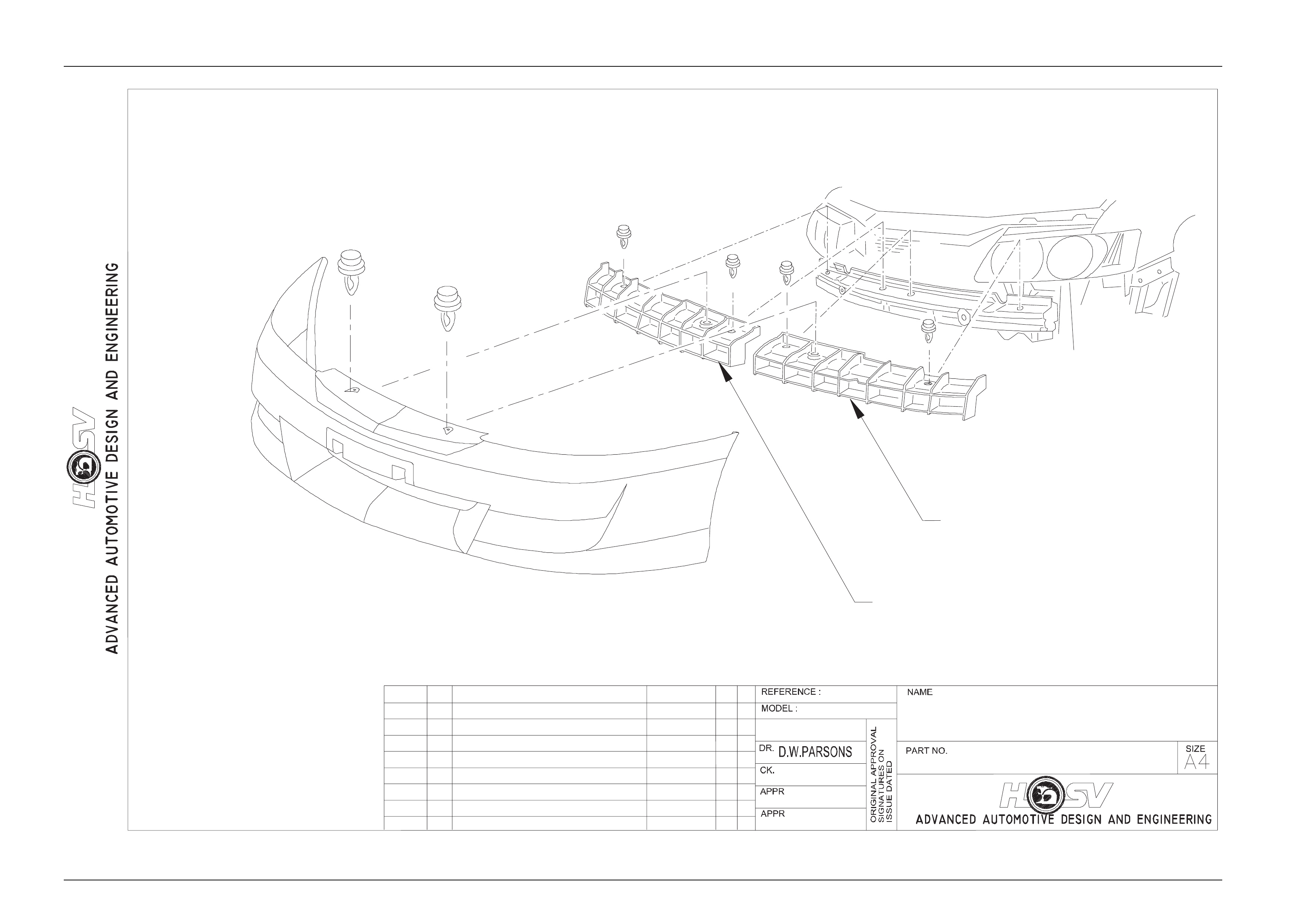
FRONTF
ACIAA
SSEMBLY
14I-040008
10AU04
AL
10AU04
A.LITTLE
14A1041301
FACIA-FRONT BUMPER
14A1031307
MESH-LOWER GIRLLE
72D-041307
SCREW
(13 PLACES)
WL GRANGE
14A1031305
PAINT PROTECTOR-LH
14A1031307
PAINT PROTECTOR-RH
12F-041306
KIT-SENSOR HARNESS
D.PARSONS
Body Page B-9
Page B-9
Body Page B-10
Page B-10
ADVANCED AUTOMOTIVE DESIGN AND ENGINEERING
INSTRUCTION DRAWING.
A4
SIZE
REVISION RECORD
PRELIMINARY ISSUE
CK.
NAME
PART NO.
CK.
REFERENCE
DWG.
DR.
DATE:
APPR
APPR
DR.
AUTH'Y
REVISION RECORD
AUTH'Y
SYM
DATE
DR.CK.
DATE
SYM
ORIGINAL APPROVAL
SIGNATURES ON
ISSUE DATED
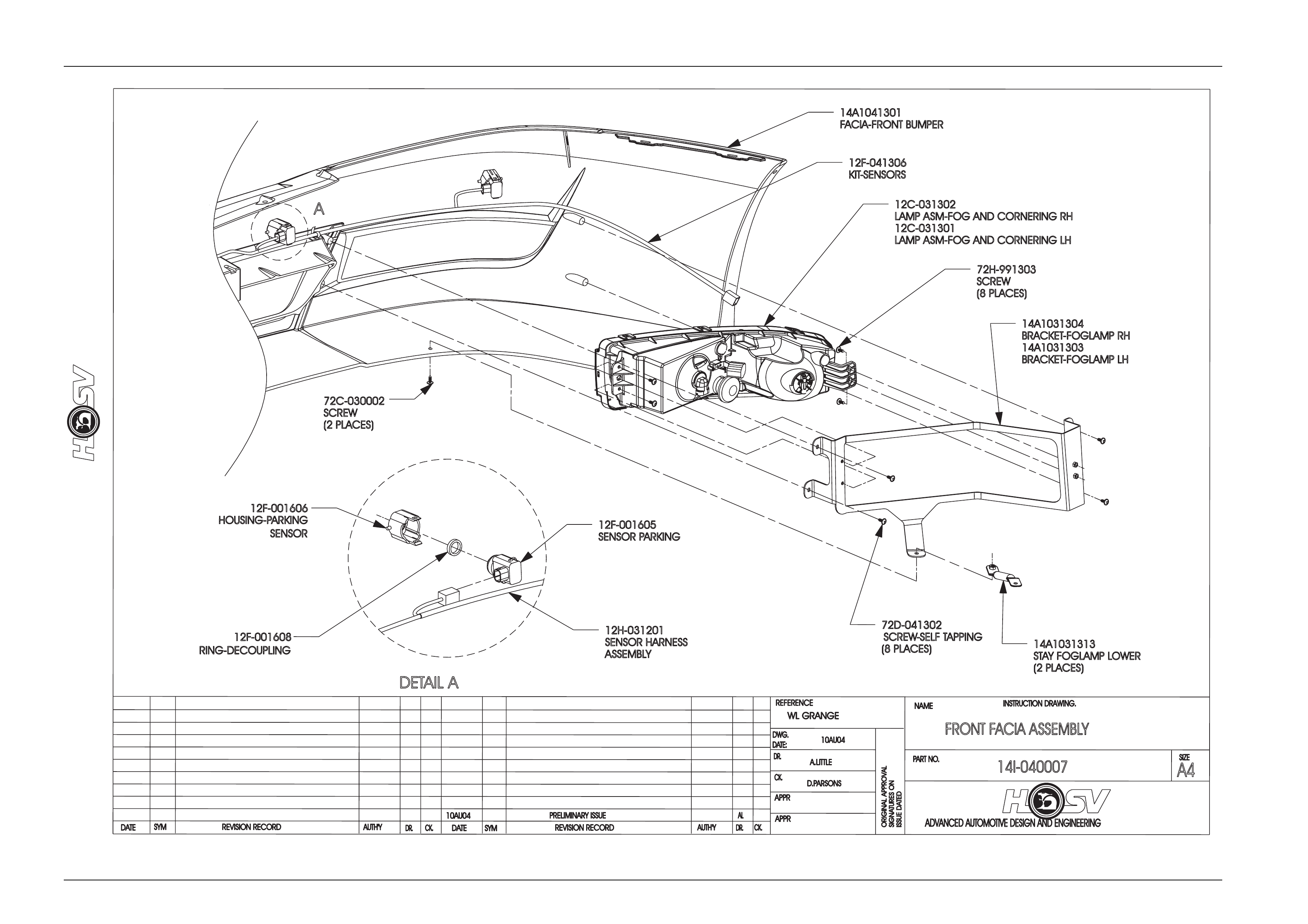
FRONTF
ACIAA
SSEMBLY
14I-040007
10AU04
AL
10AU04
A.LITTLE
14A1031304
BRACKET-FOGLAMP RH
14A1031303
BRACKET-FOGLAMP LH
72C-030002
SCREW
(2 PLACES)
12C-031302
LAMP ASM-FOGAND CORNERING RH
12C-031301
LAMP ASM-FOGAND CORNERING LH
14A1041301
FACIA-FRONT BUMPER
WL GRANGE
72H-991303
SCREW
(8 PLACES)
72D-041302
SCREW-SELF TAPPING
(8 PLACES) 14A1031313
STAYFO
GLAMP LOWER
(2 PLACES)
A
DETAIL A
12F-041306
KIT-SENSORS
12F-001606
HOUSING-PARKING
SENSOR
12F-001608
RING-DECOUPLING
12F-001605
SENSORP
ARKING
12H-031201
SENSOR HARNESS
ASSEMBLY
D.PARSONS
Body Page B-11
Page B-11
ADVANCED AUTOMOTIVE DESIGN AND ENGINEERING
INSTRUCTION DRAWING.
A4
SIZE
REVISION RECORD
PRELIMINARY ISSUE
CK.
NAME
PART NO.
CK.
REFERENCE
DWG.
DR.
DATE:
APPR
APPR
DR.
AUTH'Y
REVISION RECORD
AUTH'Y
SYM
DATE
DR.CK.
DATE
SYM
ORIGINAL APPROVAL
SIGNATURES ON
ISSUE DATED
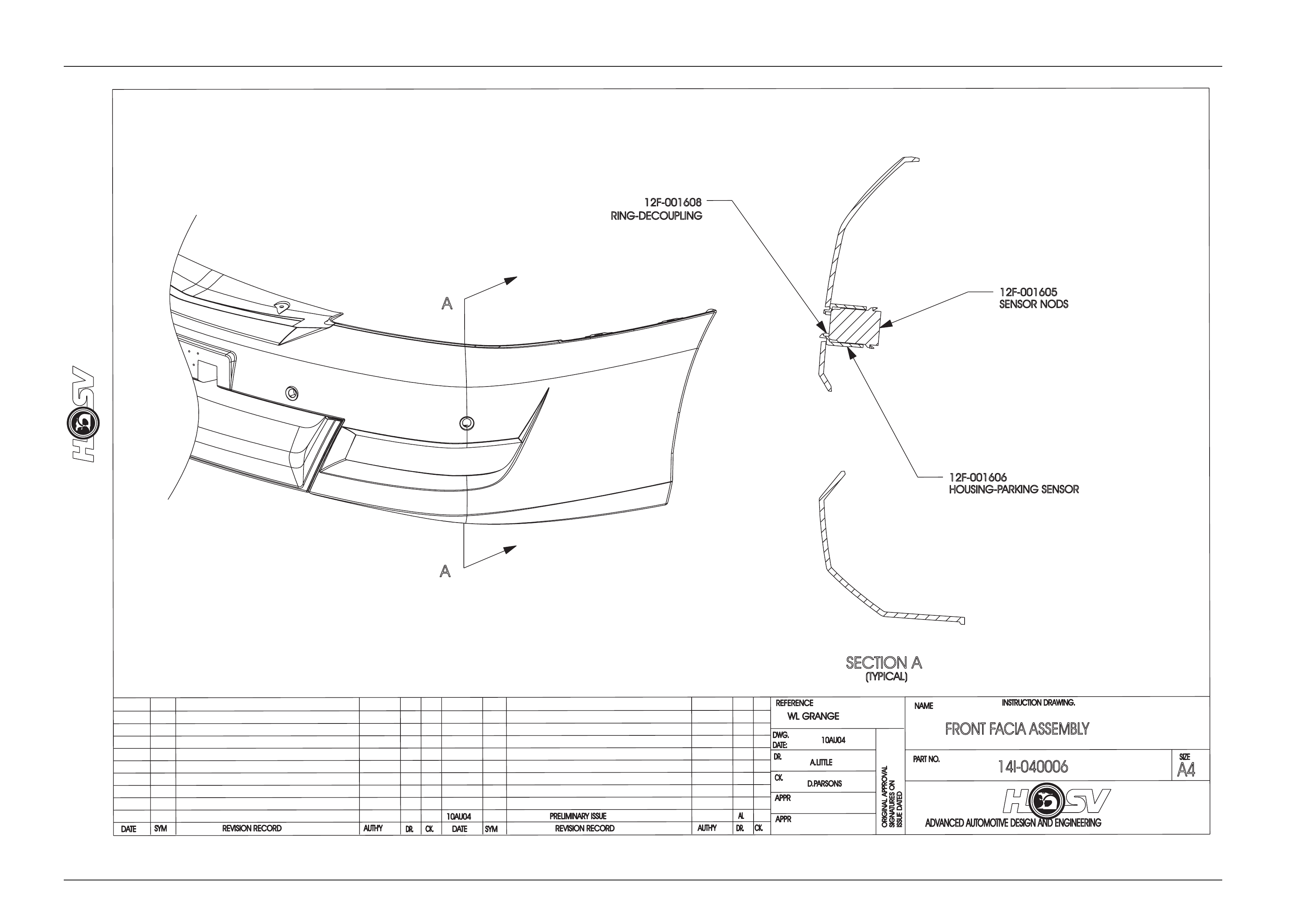
FRONTF
ACIAA
SSEMBLY
14I-040006
10AU04
AL
10AU04
A.LITTLE
A
A
SECTION A
(TYPICAL)
WL GRANGE
12F-001608
RING-DECOUPLING
12F-001605
SENSOR NODS
12F-001606
HOUSING-PARKING SENSOR
D.PARSONS
Body Page B-12
Page B-12
FRONT BUMPER
FACIA - REINFORCEMENT
14I-030020
DATE SYM REVISION RECORD
DATE:
DR.
AUTH'Y CK.
DWG.
INSTRUCTION DRAWING.
DWP
D.P
29.07.03
-
-
RELEASE
29.07.03 ECN 01048.01 MJ DP
14A1031311
SUPPORT - BUMPER FACIA
FRONT UPPER - LH
14A1031312
SUPPORT - BUMPER FACIA
FRONT UPPER - RH
Body Page B-13
Page B-13
RELEASE K.R.D
-
02.07.02
D.P
T.K
-
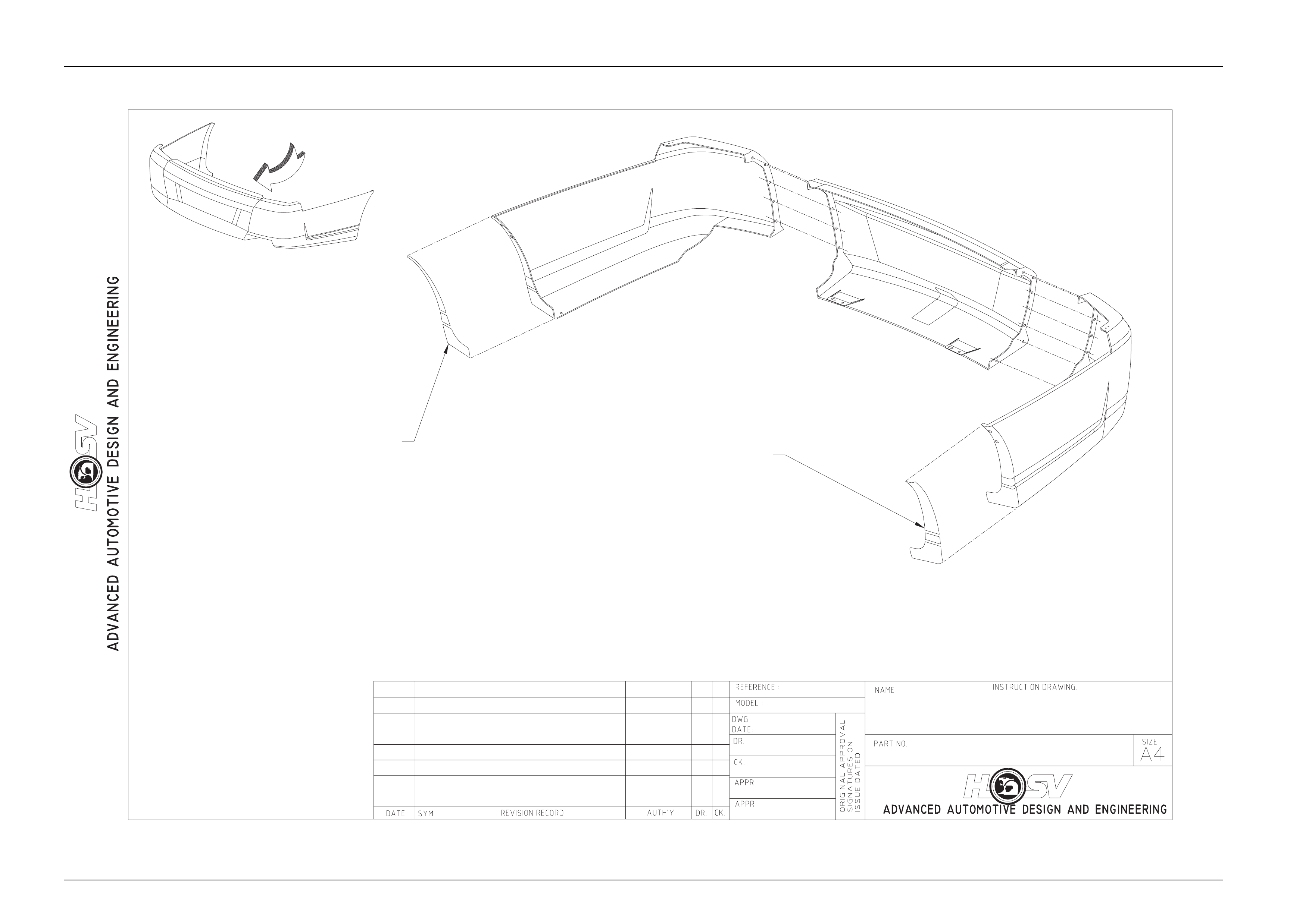
REAR BUMPER FASCIA -
GRANGE - PAINTER PROD.
14I-020010
A
VIEW A
PAINT PROTECTOR
(3 PIECE)
14A1020608/LHS
PAINT PROTECTOR
(3 PIECE)
14A1020607/RHS
Body Page B-14
Page B-14
RELEASE K.R.D
-
02.07.02
D.P
T.K
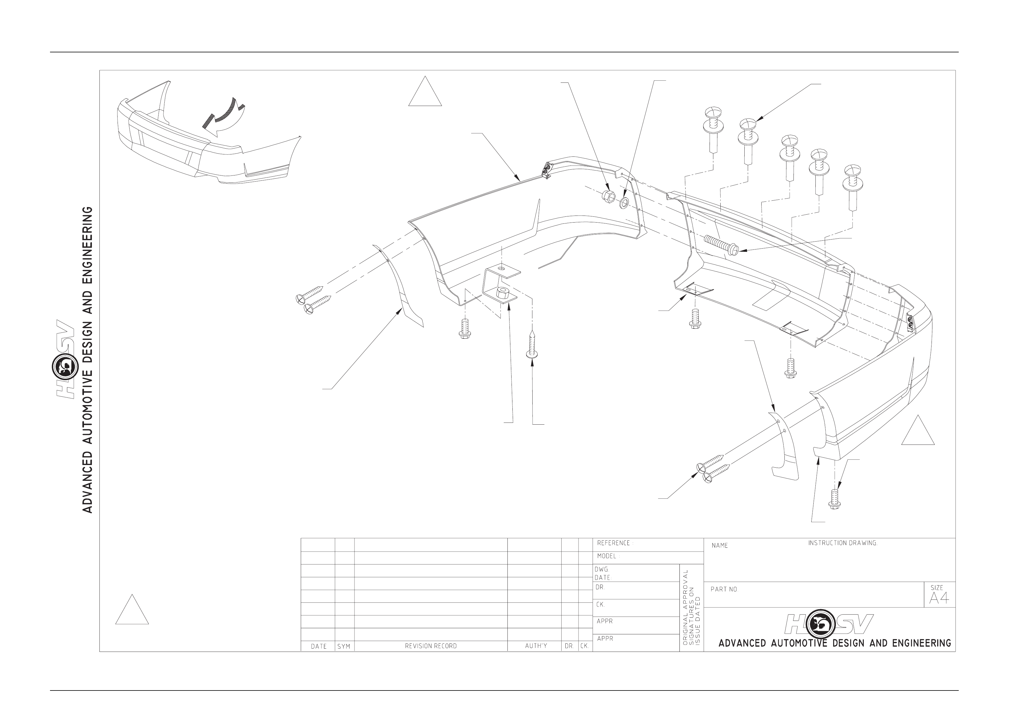
-REAR BUMPER
FASCIA - GRANGE
14I-020009
A
VIEW A
72C-020009
(4 PLACES)
72D-970601
(4 PLACES)
71A-070201
(12 PLACES)
70B-060001
(12 PLACES)
73D-711905
(12 PLACES)
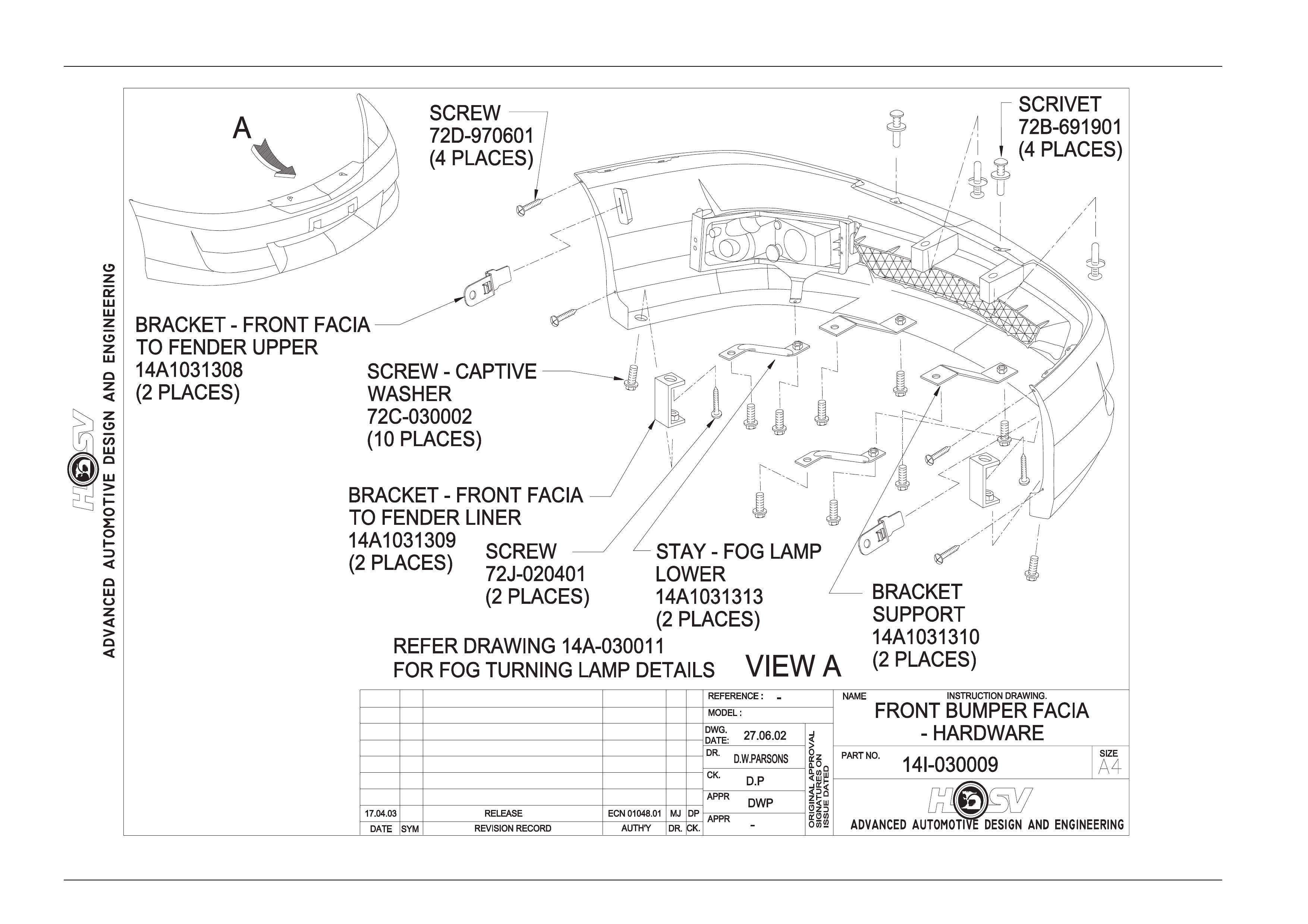
BRACKET
14A2031302
(2 PLACES)
SCREW
72J-020401
(2 PLACES)
SCRIVET
77B-691901
(8 PLACES)
17.04.03 ECN 01048.01 MJ DP
PAINT PROTECTOR
REAR - RH
14A2031310
(2 PLACES)
PAINT PROTECTOR
REAR - LH
14A2031309
(2 PLACES)
14A2031306
14A2031307
14A2031305
1
1
1 2-5Nm
Body Page B-15
Page B-15
RELEASE
-
10.04.03
D.P
MJ
-
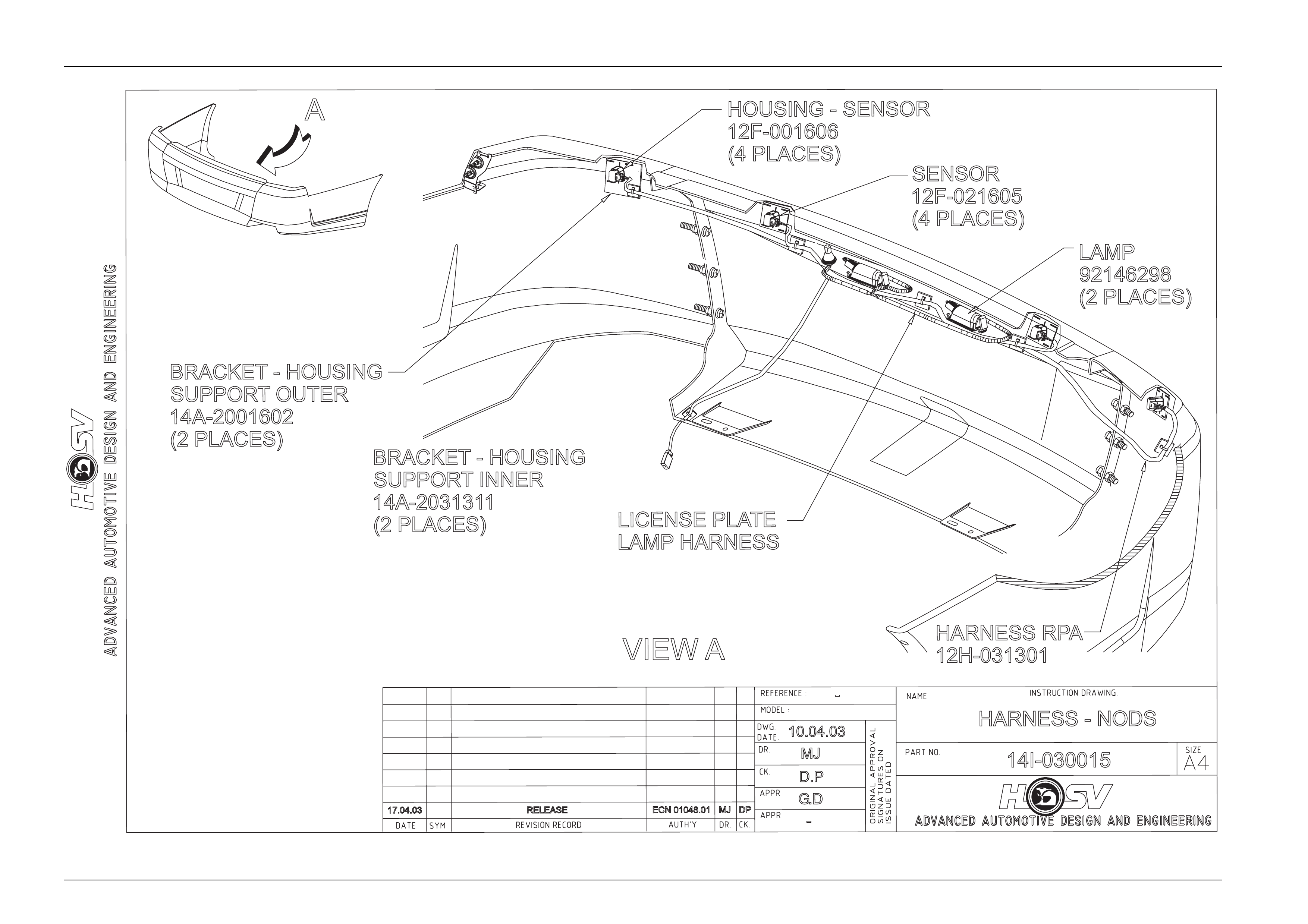
HARNESS - NODSHARNESS -NODS
14I-030015
A
VIEW A
HOUSING - SENSORHOUSING -SENSOR
12F-001606
(4 PLACES)(4 PLACES)
BRACKET - HOUSING
-HOUSING
SUPPORTOUTER
14A-2001602
(2 PLACES)(2 PLACES)
HARNESS RPHARNESS RPA
12H-031301
BRACKET - HOUSING
-HOUSING
SUPPORTINNER
14A-2031311
(2 PLACES)(2 PLACES)
SENSOR
12F-021605
(4 PLACES)(4 PLACES)
LAMP
92146298
(2 PLACES)(2 PLACES)
LICENSE PLALICENSE PLATE
LAMP HARNESS
17.04.03 ECN 01048.01ECN 01048.01 MJ DP
G.D
Body Page B-16
Page B-16
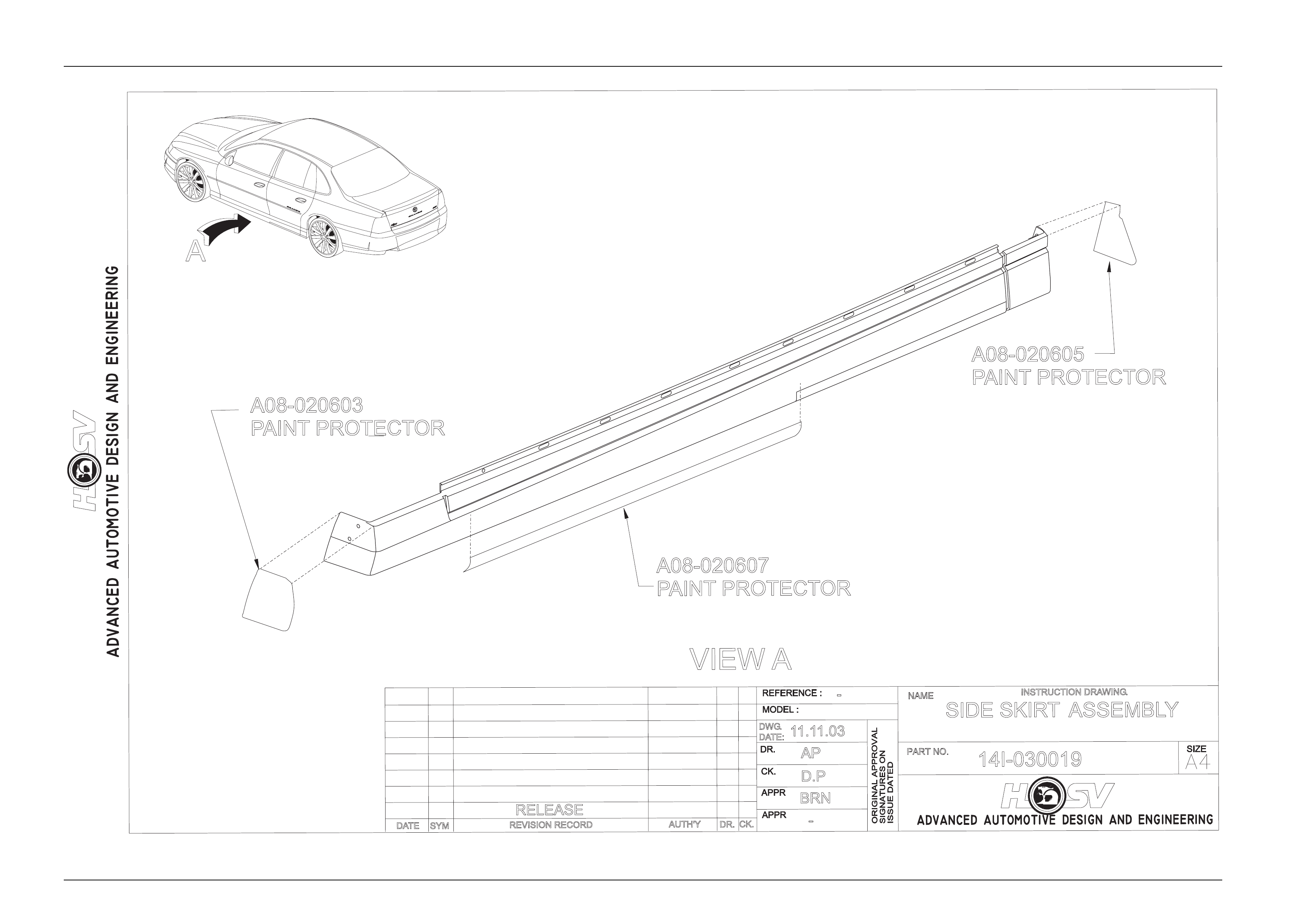
A
A08-020605
PAINT PROTECTOR
DATE REVISION RECORD
RELEASE
SYM DR.
AUTH'YCK.
BRN
-
DWG.
DATE:
11.11.03
D.P
AP
-
SIDE SKIRTASSEMBLY
14I-030019
INSTRUCTION DRAWING.
VIEW A
A08-020603
PAINT PROTECTOR
A08-020607
PAINT PROTECTOR

Body Page B-17
Page B-17
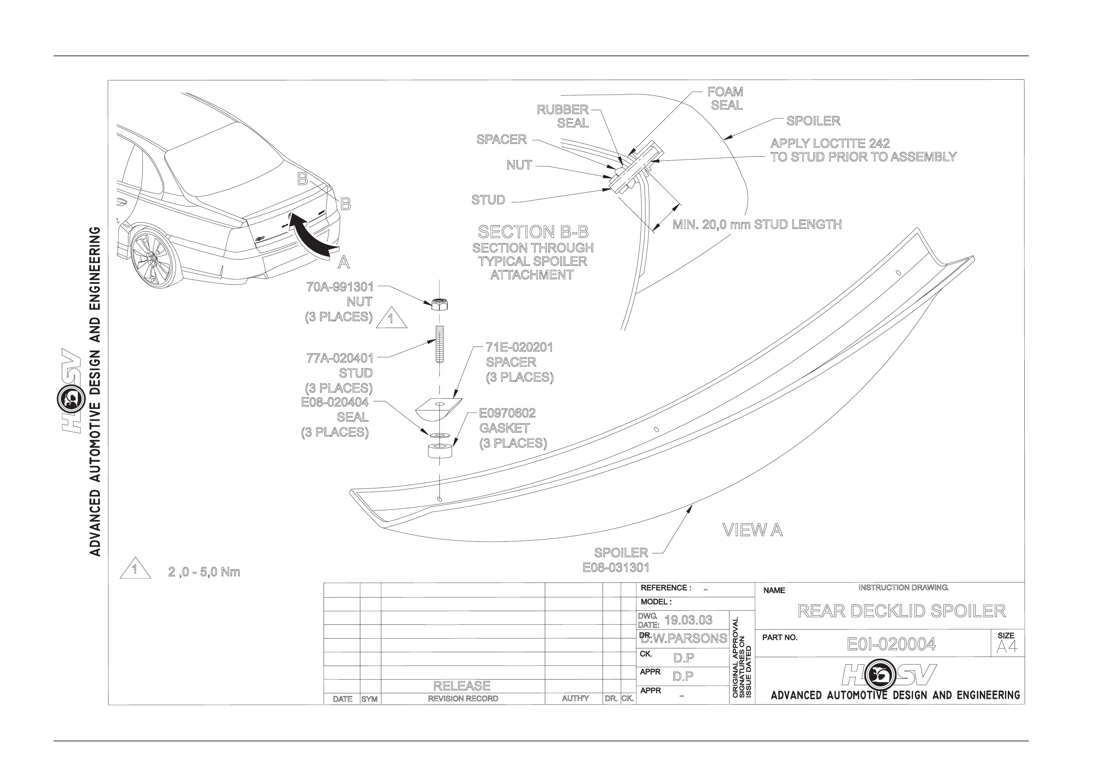
4 Rear Spoiler Service Procedure
To Service the HSV Grange Rear Decklid Spoiler the Rear Compartment Lid Carpet must be carefull y removed.
To complete this refer to the Holden Service Procedure outlined in Section 1A4 Hood and Rear Compartment Lid of the
Holden WL Statesman Service manual and HSV Drawing number E0I-020004.
Body Page B-18
Page B-18
B
B
70A-991301
NUT
(3 PLACES)
E08-020404
SEAL
(3 PLACES)
E0970602
GASKET
(3 PLACES)
STUD
SPOILER
SPACER
77A-020401
STUD
(3 PLACES)
71E-020201
SPACER
(3 PLACES)
FOAM
SEAL
MIN. 20,0 mm STUD LENGTH
APPLYLOCTITE 242
TO STUD PRIOR TOASSEMBLY
1
12 ,0 - 5,0 Nm
SPOILER
DATE REVISION RECORD
RELEASE
SYM DR.
AUTH'Y CK.
D.P
-
DWG.
DATE:
19.03.03
D.P
D.W.PARSONS
-
REAR DECKLID SPOILER
E0I-020004
INSTRUCTION DRAWING.
A
VIEW A
E08-031301
RUBBER
SEAL
SECTION THROUGH
TYPICAL SPOILER
ATTACHMENT
SECTION B-B
NUT

Body Page B-19
Page B-19
5 WL Rear Decklid Spoiler
In the event that the rear deck lid requires repl acement, a replacement decklid must be ordered through your local
authorised HSV dealer to ens ure correct fitment of your body styling package.

Body Page B-20
Page B-20
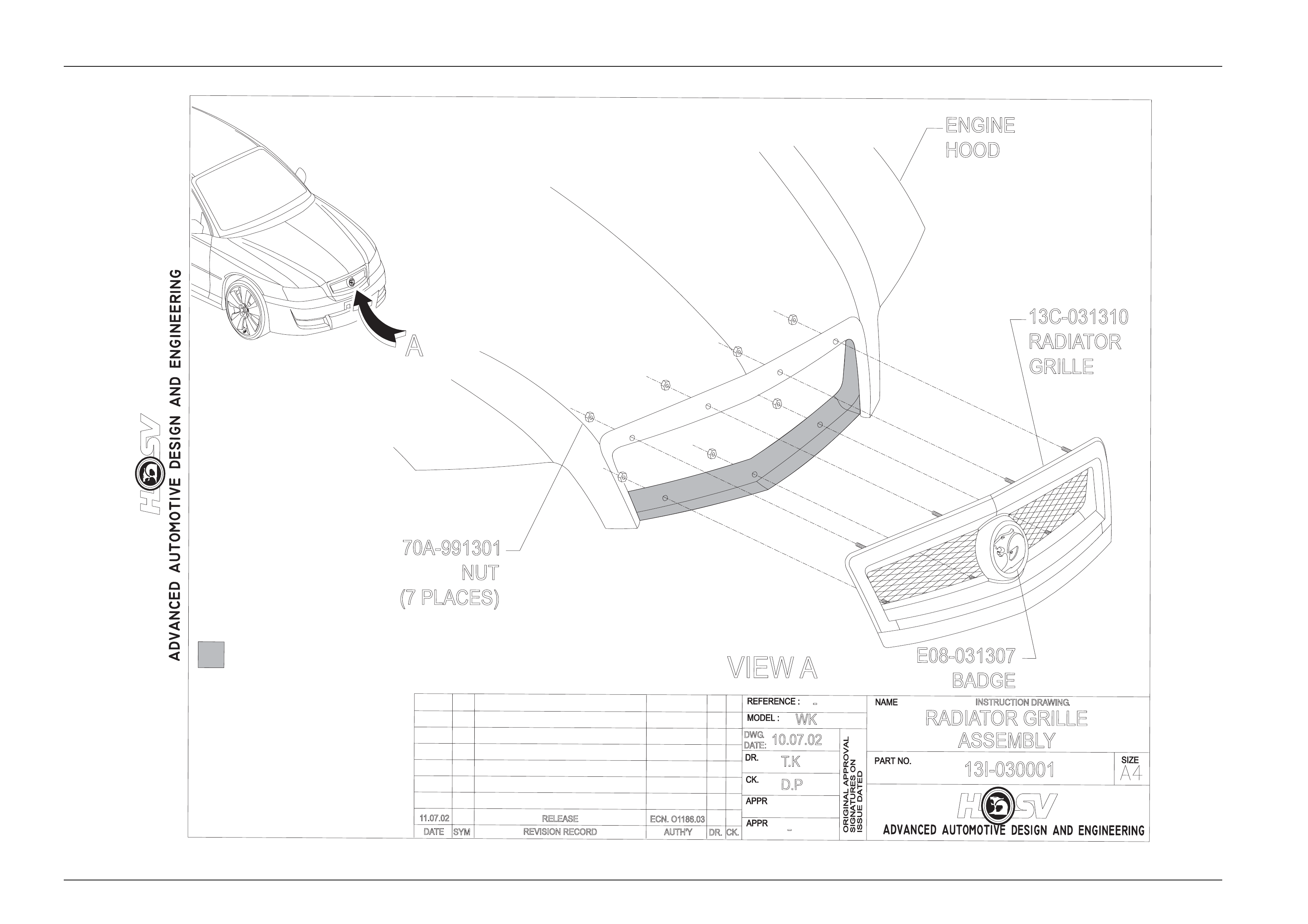
6 WL Radiator Grille
The Radiator Grille for the HSV WL Grange is a unique d esign, please refer to drawing number 13I-030001.
Removal
1. Open Engine Hood.
2. Loosen the 4 lower grille attaching nuts and washers.
3. Loosen and remove the upper outer attaching nuts and washers.
4. While supporting the sight shield, loose n and remove the upper inner attaching nuts and washers. Take care not to
dislodge the round spacers located on the center studs under the sight shield.
5. Lower the sight shield down the stud, this will give access to hold the spacer while the sight shield is rem oved.
6. Remove the sight shield.
7. Remove the spacer.
8. Remove the lower nuts and washers.
9. Remove the grille assembly from the hood panel.
Assembly
1. Using the centrally located guide pin assemble the grille into the engine hood recess 7 hood attaching holes
located in the grille recess.
2. Loosely attach both the LH & RH lower mounting nuts and washers.
3. Applying pressure on the RH bottom corner of the grille, gently push the grille upward in t he hood recess and
tighten the RH lower nut (2.0 – 5.0 Nm).
4. Repeat this procedure on the LH bottom corner of the assembly.
5. Loosely assemble the spacers, sight shields, washers and nuts to the grille inner upper attaching studs.
6. Loosely assemble the washers and nuts to the outer u pp er grill e studs.
7. Apply pressure to the to the RH top corner of the grille outer face to seat the grille into the hood recess while
torquing the attaching nut (2.0 – 5.0 Nm).
8. Repeat this procedure on the LH top corner of the assembly.
9. Torque up the center attaching nuts (2.0 – 5.0 Nm).
Body Page B-21
Page B-21
RELEASE
REVISION RECORD
SYM
DATE
INSTRUCTION DRAWING.
AUTH'Y CK.
DR.
-
WK
T.K
D.P
10.07.02
DWG.
DATE:
13I-030001
-
RADIATOR GRILLE
ASSEMBLY
VIEW A
A
13C-031310
RADIATOR
GRILLE
70A-991301
NUT
(7 PLACES)
11.07.02 ECN. O1186.03
E08-031307
BADGE
ENGINE
HOOD
AREA TOBE PAINTED WITH
SUBFRAME SEMI-GLOSS BLACK

Body Page B-22
Page B-22
RELEASE
REVISION RECORD
SYM
DATE
INSTRUCTION DRAWING.
AUTH'YCK.
DR.
-
DWP
DWP
19.03.02
DWG.
DATE:
-
RADIATORG
RILLE
PAINT
19.03.03 ECN. 01186.05
13I-030002
PAINT AREA BELOWPAINT GROOVE BODY COLOUR

Body Page B-23
Page B-23
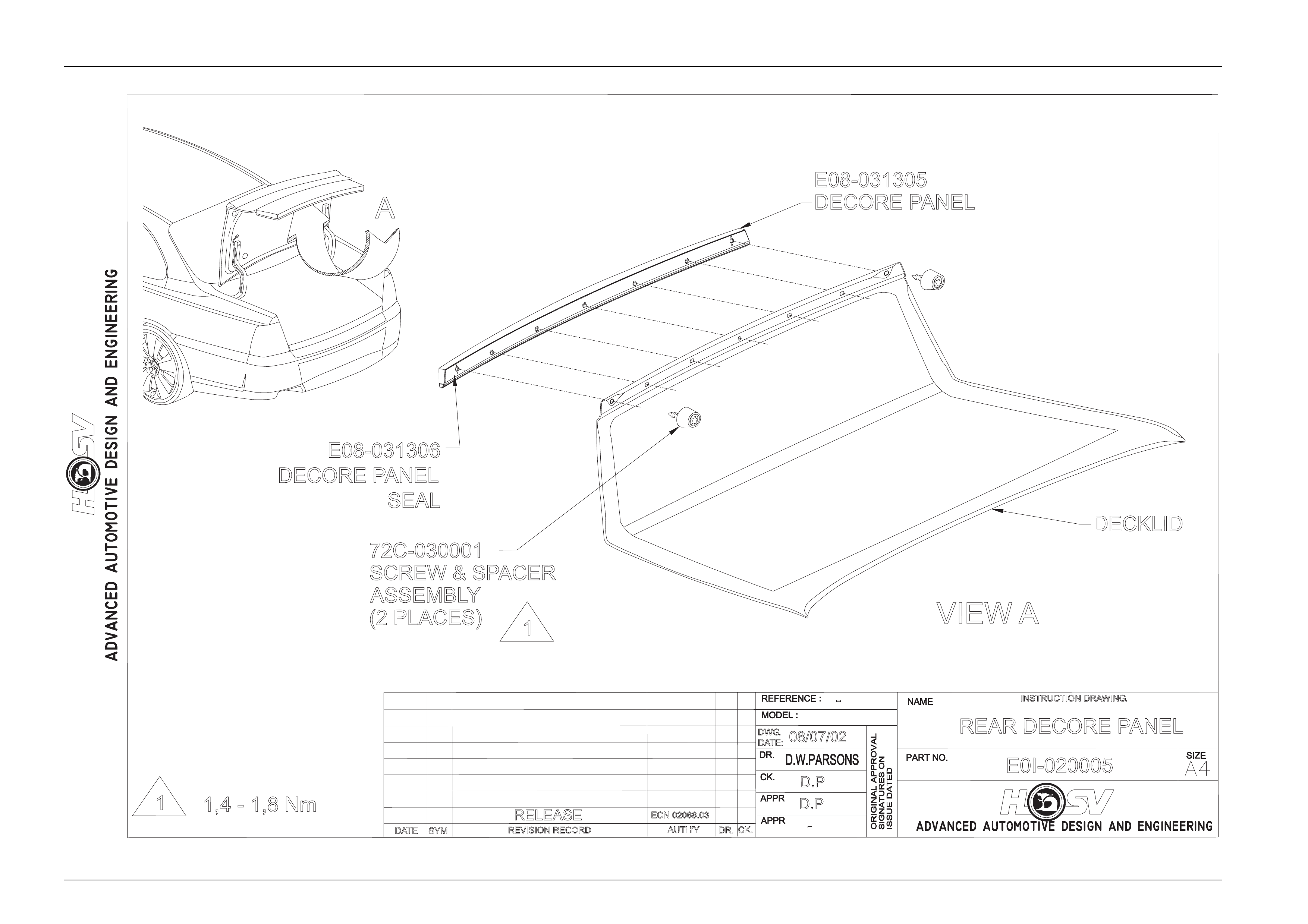
7 WL Rear Décor Panel
The Rear Décor Panel for the HSV WL Grange is a un ique design, please refer to drawing number E0I-020005.
Removal
1. Open deck lid.
2. Remove the 2 end attaching screw and spacer assemblies. T he Torx head screws and spacers locate against the
deck lid Inner panel.
3. Remove the rear compartment lid pull handle located on the LH side of the rear comp artment lid inner panel, this is
a snap in part and is removed b y pul ling and rotating the handle down.
4. Remove the carpet retaining clips located along the bottom edge of the rear compartment lid.
5. Gently pull the carpet over the lock and switch, peal the carpet back to allow access to the inner panel.
6. Remove the rear compartment lock assembly.
Refer to Section 1A4 Hood, Rear Compartment Lid, Liftgate and Endgate of the Holden MY2005 WL Service
Information.
7. Using a suitable Phillips h ea d screwdriver remove the center attaching scre w for the décor panel. Care must be
used so as not to drop the screw into the cavity between the inner and outer panels.
8. Remove the décor panel from the rear compar tment lid by lifting a nd rotating, care must be used not to damage the
panel surface.
Assembly
1. With the center attaching screw taped to a suitable Phillips head screwdriver insert the screw into the center
attaching hole in the compartment lid.
2. Offer the central attaching hole in the décor panel up to the exposed screw thread.
3. With the screw engaged in the décor panel tighten the screw 2 turns. This will assemble the screw temporarily to
the décor.
4. Clip the décor to the compartment outer panel while guiding the outer mounting bosses throu gh their attaching
slots.
5. Install the outer mounting screw and spacers. Tighten the scre w to a torque of 2.0 – 5.0 Nm.
6. Tighten the center attaching screw to 5.0 – 8.0 Nm. If a gap exists at its center between the décor and the outer
panel, tighten the center screw until the décor seats on the outer panel.
7. Care must be taken not to damage or dislodge the décor panel seal during the fitment of the parts.
8. Reassemble the lock and the carpet assembly.
Refer to Section 1A4 Hood, Rear Compartment Lid, Liftgate and Endgate of the Holden MY2005 WL Service
Information.
Body Page B-24
Page B-24
DATE REVISION RECORD
RELEASE
SYM DR.
AUTH'Y CK.
D.P
-
DWG.
DATE: 08/07/02
D.P
-
REAR DECORE PANEL
E0I-020005
INSTRUCTION DRAWING.
VIEW A
DECKLID
E08-031306
DECORE PANEL
SEAL
E08-031305
DECORE PANEL
72C-030001
SCREW & SPACER
ASSEMBLY
(2 PLACES)
A
ECN 02068.03
1
11,4 - 1,8 Nm

Body Page B-25
Page B-25
8 WL Fender Vent Service
Procedures
Removal
1. Raise the vehicle on a suitabl e Hoist takin g care not to damage the Si de Skirts and also allowing access to the
lower Side Skirt attaching Screws.
2. Remove Side Skirt. - Refer to Side Skirt Drawing 14I-030019.
3. Remove Front Fender Liner attaching Scrivets and Screws. Pull the Liner downwards to remove it from the
Wheelhouse.
Globe
From inside the Fender wheelhouse the globe socket can be removed by turning anti-clockwise and withdrawing it
inboard. Installation is the reverse of the removal procedure.
Vent
From inside the Fender wheelhouse the vent can be removed by depressing the attaching Clips legs (2 per clip and 2
clips per vent) toward each other using a set of “pointy nosed” pliers or similar. At the same time gently pull the lower
edge of the Vent away from the Fender. On the Left side the rear clip may not be accessi ble b ecause of the power
antenna. In this case, after disengaging the front clip, pull the forward end of the vent down and forward leaving the rear
clip in the fender.
Installation
The Installation of the Fender Vent is the rev erse of the removal procedure with the follo wing e xceptions.
1. Ensure that the 3 rubber strips and 2 clips are attached to the vent.
2. Slide the vent in and up over the 3 metal tabs at the top of the fender opening and rotate it inboard at the bottom
until the clips are engaged.
3. Install the Side Skirt if it has been removed but Do Not install the 2 Side Skirt front attaching Screws.
4. Install the front Fender liners by first feeding the rear edge of the Fender Liner in between the Side Skirt front
flange and the Side Skirt body attaching bracket. Then push the remainder of the Fender Liner into position ensure
the Fender Liner is pulled toward the outside of the vehicle and its outside edge is ab ove and overlapping the
Fender Flange before installing the attaching Screws and Scrivets.
5. Install the Side Skirt Front attaching Screws.
NOTE
If the Vent is to be replaced with a new one, the
individual items must be assembled in the
following sequence:
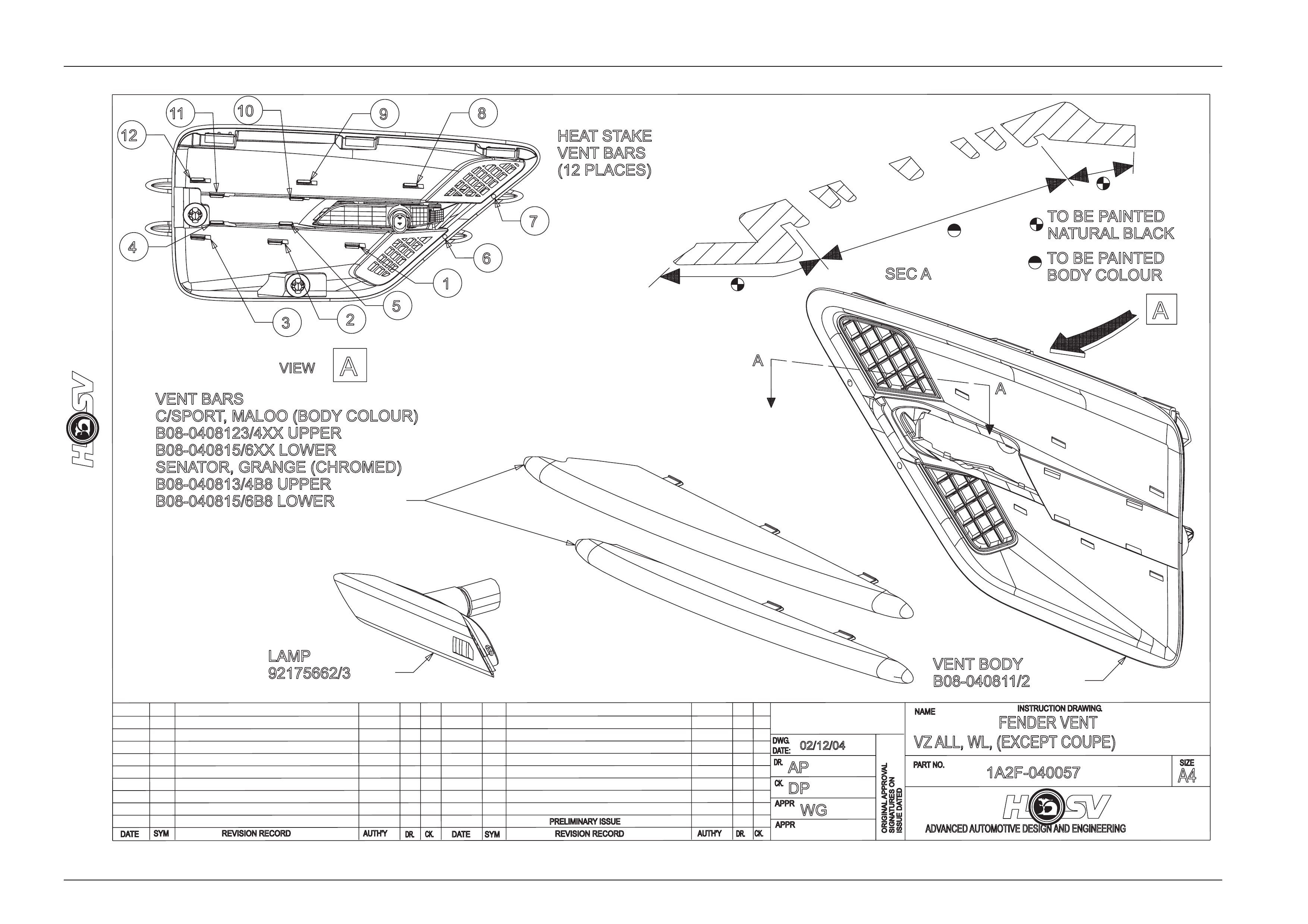
6. Paint the Vent body B08-040811/12 L/RH, Upper bar B08-040813/14 L/RH and Lower bar B08-0408 15/6 L/RH as
required. (Bars for Senator and Grange B08-040813/4/5/6B8, are chrome plated and don’t require painting)
7. Assemble the Turn Signal Lam p 92175662/3 L/RH to the Vent body. Sn aps in from outside.
8. Snap the bars into the slots in the base over the lamp and heat stake tabs from behind using a hot soldering iron or
equivalent. Take care not to damage the e xternal finish and ensure slots are not visible from the outside. Push tabs
to the outside of the slots if necessary before staking. Clamp or hold together until plastic has sol idified.
9. Install new vent as above.
Body Page B-26
Page B-26
Body Page B-27
Page B-27
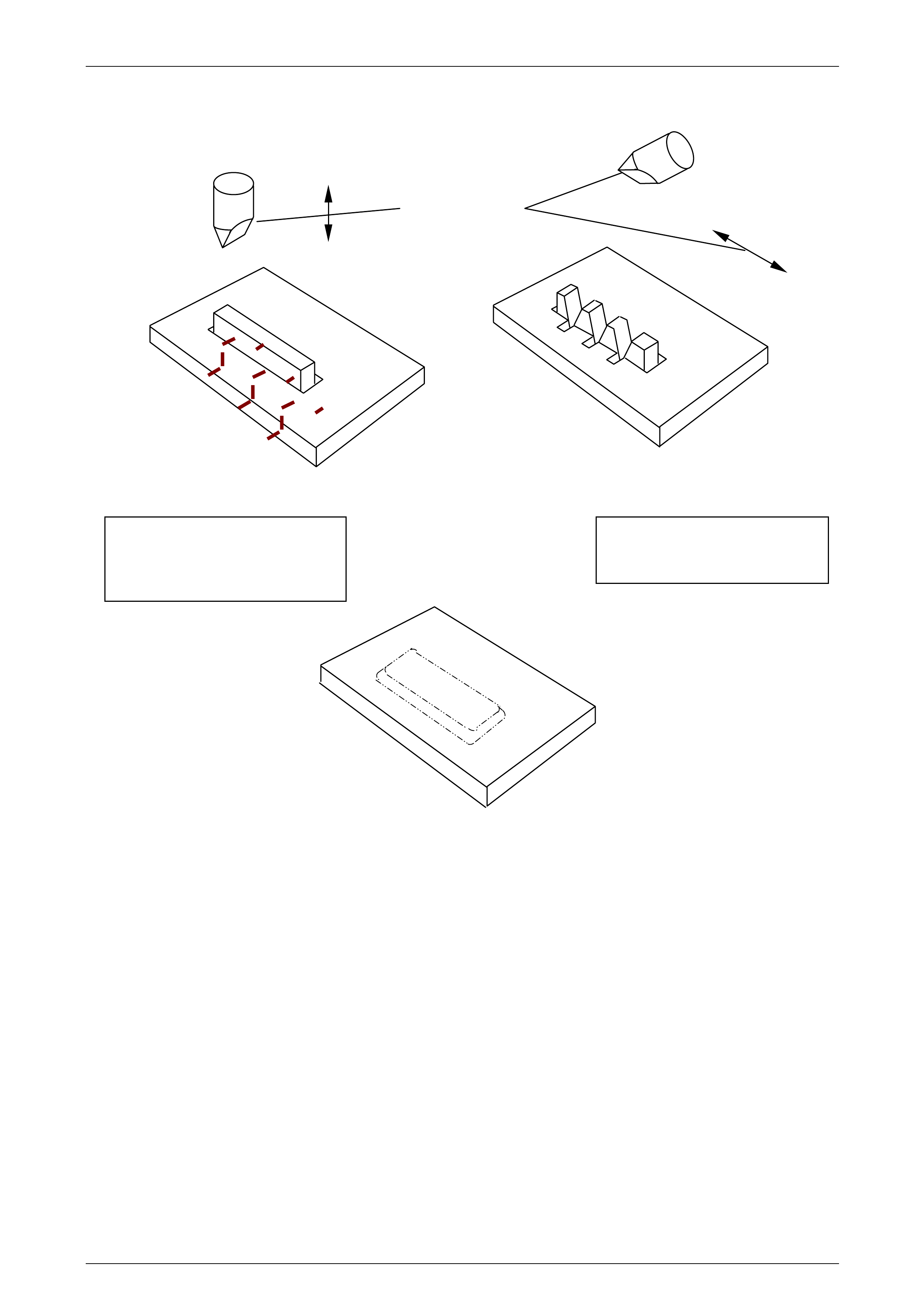
Heat Staking Procedure
Step 1 Step 2
Finished
Soldering Iron and
movement direction
on
Melt material across blade and into
base in leaving material sev eral
places taking care not to distort
outer visible surface
Smooth and fill initial cuts proud
of base to avoid excess thinning
over
j
oint.