
Brakes Page D-1
Page D-1
Section D
Brakes
ATTENTION
HSV vehicles are equipped with a Supplemental Restraint System (SRS). An SRS consists of seat belt pre-
tensioners (fitted to all front seats), a d river’s-side air bag, a passeng er’s-side air bag and right and left h and
side air bags. Refer to CAUTIONS, Section 12M, of the Holden WL Service Information before performing any
service operation on or around SRS components, the steering mechanism or wiring. Failure to follow the
CAUTIONS could result in personal injury or unnecessary SRS system repairs.
1 Purpose...................................................................................................................................................2
2 Brakes......................................................................................................................................................3
2.1 General Information............................................................................................................................................... 3
2.2 Service Operations................................................................................................................................................ 4
Pad Replacement................................................................................................................................................... 4
Calliper Overhaul................................................................................................................................................... 4
Brake Discs ............................................................................................................................................................ 5
2.3 Service Parts.......................................................................................................................................................... 6
Front Callipers........................................................................................................................................................ 6
Rear Callipers......................................................................................................................................................... 7

Brakes Page D-2
Page D-2
1 Purpose
The purpose of this section is to provide information on the Brake Systems fitted to HSV WL model. Details are given
where differences occur between the HSV models and standard Holden models. A series of instruction drawings
describe the design changes and indicate specific part numbers, fitting instructions and relevant notes for vehicle
servicing.
NOTE
If specific technical data on a HSV model is not
contained in this supplement, obtain data for that
model from Section 5A Service and Park Brakin g
Systems of the WL Service Information.
References are made throughout this section to
Holden Service Information to assist in providing
information for specific service operations.
When hoisting (or jacking) HSV models,
ensure that the lifting h ead o f th e hoist lifts on
the chassis before the arm of the hoist
contacts the side-skirt

Brakes Page D-3
Page D-3
2 Brakes
2.1 General Information
Brake systems fitted to HSV WL model employ the vacuum boosted, four-wheel-disc concept operating through a
tandem master cylinder. T his tandem arra ng e ment prov ides separ ate brak i ng s ystems to the front and rear wheels which
in turn, provides adequate bra king (to the front or rear wheels) if a fault occurs in either system. HSV WL model is also
equipped with the BOSCH Anti-lock Braki ng System (ABS) as standard. Inspection, replacement and testing of the ABS
must be carried out in accordance with the procedures detailed in the relevant Holden Service Information.
Whenever any component of the ABS is
disturbed during service operations, it is vital
that the complete ABS is checked using the
procedure detailed in the relevant Holden
Service Information.
Model Premium Performance
GRANGE --- S
Table D-1 Brake System

Brakes Page D-4
Page D-4
2.2 Service Operations
Although HSV brake systems have different fittings and components, the general service principles are the same as
those which apply to Holden standard brake systems. The important differences between Holden brake systems and
HSV systems are the component parts and the specified wear limits for those parts. Drawings of specific HSV brake
systems and component part numbers are included in this section and wear limits have also been specified where
required.
Pad Replacement
Refer to appropriate dra wings in this section or in Holden Service Information. Ensure that the follo wing important notes
are observed and replace brake pads in accordance with the procedures in the Holden WL Series Service Information.
Important Notes On Brake P ad Replacement
• Do not remove mounting brackets unless damaged or for disc servicing.
• Pads should be replaced if there is less than 3mm of lining material r emaining or if pads are damaged.
• Pads must be replaced as a full set of 4. Ensure pad material is correct specificati on. Do not mix pad material front
to rear. Use genuine HSV replacement parts to ensure correct pad material is used.
• Before fitting new pads check that all pads are fitted with insulati ng material.
When replacing pads in Perfo rmance brakes, ensure that shims and spring are fully clipped into position so that the y are
clear of the rotor. Carefully lower the body over the pads and bracket ensuring the pa ds are engaged with spring so that
they are free to slide. Ensure Piston Boot is not caught between the Piston and the inn er pad. Fit new guide bolt through
the lower hole and tighten to a torque of 30-34 Nm.
Calliper Overhaul
Refer to appropriate dra wings in this section or in Holden Service Information. Ensure that the follo wing important notes
are observed and overhaul callipers as detailed in Section 5A Service and Park Braking Systems of the WL series
Service Information.
Notes On Calliper Overhaul
• Do not remove the mounting brackets unless damaged or for disc servicin g.
• Remove the pistons by directing light air pressure into the brake h ose port, and progressively increase until piston
is forced out of bore .
Caution is necessary to avoid physical
injury—Piston may be ejected with
considerable force due to air pressure. Use
packing to prevent piston damaging body of
calliper.

Brakes Page D-5
Page D-5
Brake Discs
Refer to appropriate dra wings in this section or in Holden S ervice Information. Ensure tha t important notes are o bserved
and overhaul discs as detaile d in Section 5A Service and Park Braking S ystems.
Do not remove mounting bracket from the
brake calliper unless the bracket requires
service. It is critical for safety that the bolts
holding the mounting bracket to the calliper if
removed, are correctly reinstalled.
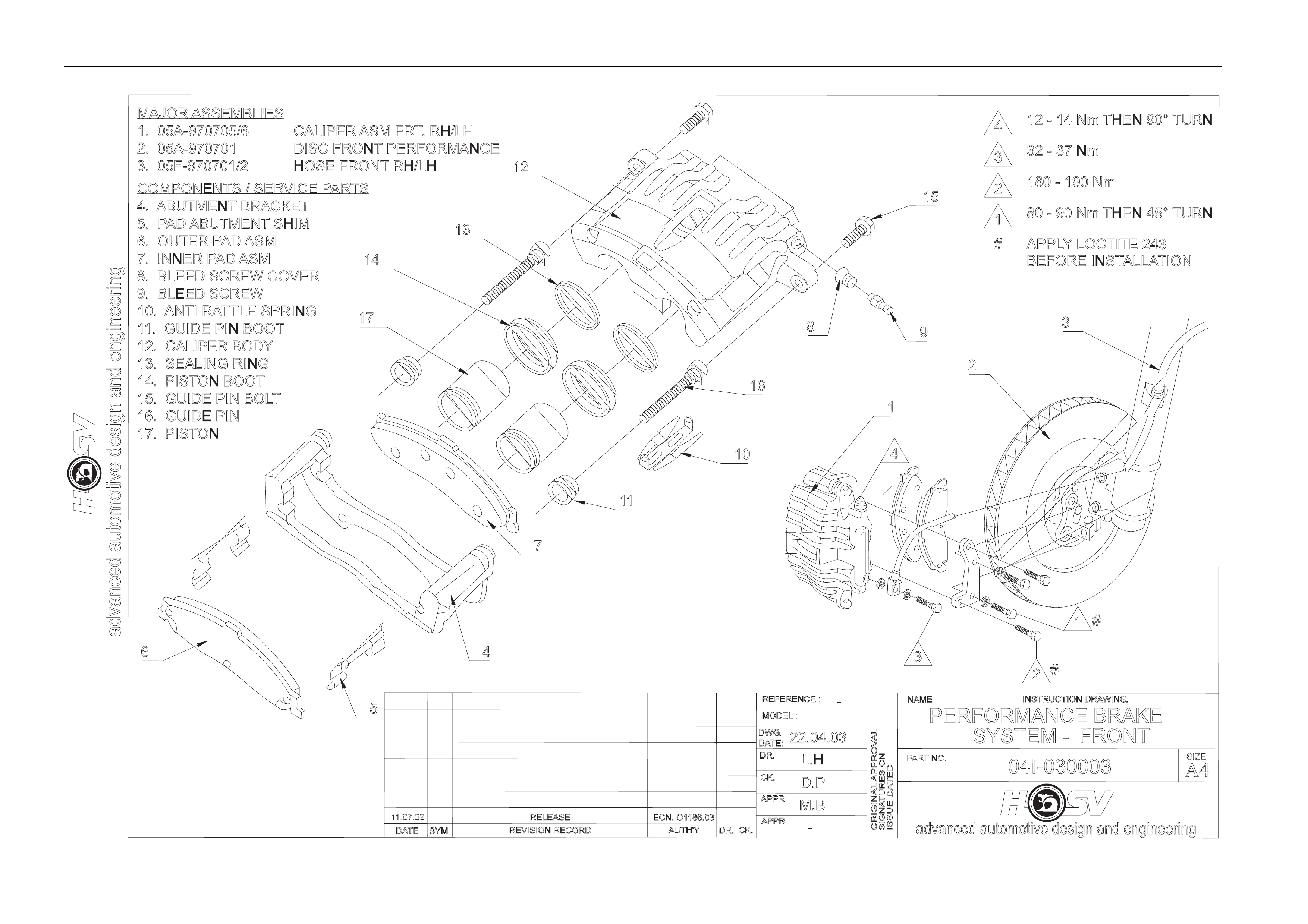
Refer Drawing No. 04I-030003 for assembly
requirements.
Brake Disc Wear Limits.
The minimum thickness for discs fitted to standard Holden brakes is cast in the hub of the disc and is specified in
Section 5A Service and Park Braking S ystems in the Holden Service Info rmation. T he minimum th ickne ss for brake dis cs
fitted to HSV brake systems is stamped into the ed ge of the disc. For information, the new and minim um thicknesses of
discs used in HSV brake systems are tabulated be low.
Disc Location New Thickness Minimum Thickness
FRONT
REAR
32.0 mm
18.0 mm
30.0 mm
16.0 mm

Brakes Page D-6
Page D-6
2.3 Service Parts
It is essential that genuine replacement parts be fitted to HSV brake assemblies. This is particularly important when
replacing brake pads because of the various types of lining material used. Complete brake assemblies, front and rear
discs, callipers and attachm ent parts have also been identif ied as replacement parts and t hese items are available from
HSV. These parts are listed in the follo wing paragraphs or referenced in enclosed drawings.
Front Callipers
05A-970730 FRONT HYDRAULIC REPAIR KIT COMPRISING
2 OFF SEALING RINGS
2 OFF PISTON BOOT
1 OFF BLEED SCREW PROTECTION COVER
2 OFF GUIDE PIN BOOT
05A-030702 FRONT CALLIPER HOUSING ASSEMBLY RH COMPRISING
1 OFF CALLIPER BODY RH
1 OFF ABUTMENT BODY
2 OFF PAD ABUTMENT SHIM
2 OFF SEALING RING
2 OFF PISTON BOOT
2 OFF PISTON
1 OFF BLEED SCREW PROTECTOR COVER
1 OFF BLEED SCREW
1 OFF ANTI RATTLE SPRING
2 OFF GUIDE PIN BOOT
2 OFF GUIDE PIN
2 OFF GUIDE PIN BOLT
05A-030701 FRONT CALLIPER HOUSING ASSEMBLY LH COMPRISING
1 OFF CALLIPER BODY RH
1 OFF ABUTMENT BODY
2 OFF PAD ABUTMENT SHIM
2 OFF SEALING RING
2 OFF PISTON BOOT
2 OFF PISTON
1 OFF BLEED SCREW PROTECTOR COVER
1 OFF BLEED SCREW
1 OFF ANTI RATTLE SPRING
2 OFF GUIDE PIN BOOT
2 OFF GUIDE PIN
2 OFF GUIDE PIN BOLT
05A-970733 PISTON BRAKE
05A-970734 BLEED SCREW
05A-970735 PAD ABUTM ENT SHIM
05A-970736 ANTI RATTLE SPRING
05A-970737 GUIDE PIN
05A-970738 GUIDE PIN BOLT
05A-990704 BRAKE PAD KIT JBI NF42 COMPRISING
2 OFF OUTER PAD ASSEMBLY JBI NF42
2 OFF INNER PAD ASSEMBLY JBI NF42
4 OFF GUIDE PIN BOLT

Brakes Page D-7
Page D-7
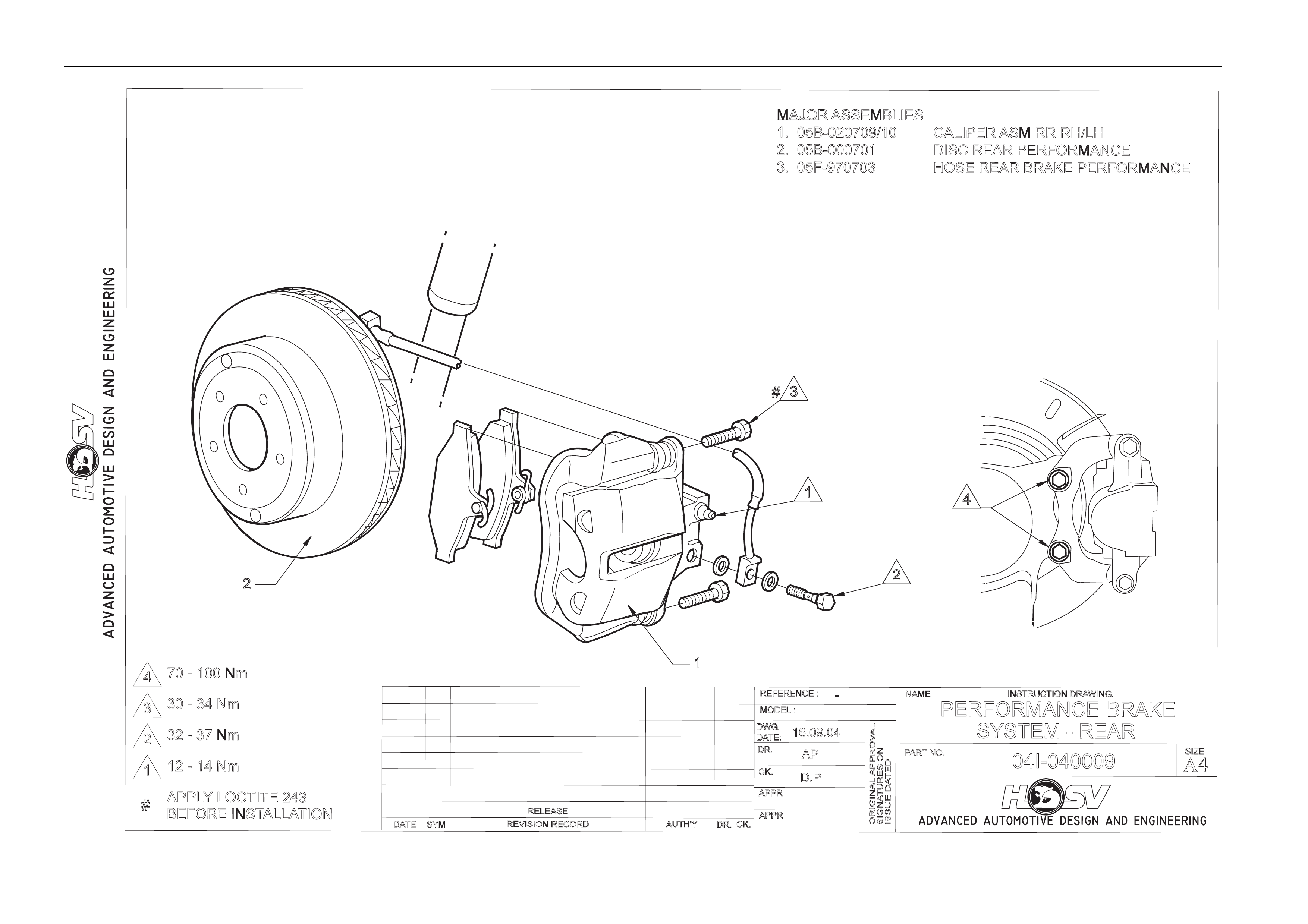
Rear Callipers
Servicing procedures and servicing kits for the WL Performance Rear Caliper are exactly the same as for the standard
WL Holden Rear Caliper. T herefore, when servicing the WL rear caliper, refer to the procedures in the
Section 5A Service and Park Braking Systems.
HSV Performance Rear Calipers use uniq ue brake pads, with a thinner pad to suit HSV’s wider ventilated disc.
05B-020710 REAR CALLIPER HOUSING ASSY RH COMPRISING
1 OFF CALLIPER BODY
1 OFF SEALING RING
1 OFF CALLIPER PISTON
1 OFF DUSTBOOT
1 OFF BLEED SCREW
1 OFF BLEED SCREW DUST CAP
05B-020709 REAR CALLIPER HOUSING ASSY LH COMPRISING
1 OFF CALLIPER BODY
1 OFF SEALING RING
1 OFF CALLIPER PISTON
1 OFF DUSTBOOT
1 OFF BLEED SCREW
1 OFF BLEED SCREW DUST CAP
05B-970704 REAR BRAKE PAD KIT (BM962) COMPRISING
4 OFF BRAKE PAD (BM962)
4 OFF RETAINING BOLTS
Brakes Page D-8
Page D-8
advanced automotive design and engineering
RELEASE
REVISION RECORD
SYM
DATE
INSTRUCTION DRAWING.
advanced automotive design and engineering
SIGNATURES ON
ISSUE DATED
ORIGINAL APPROVAL
AUTH'YCK.
DR.
-
APPR
L.H
D.P
22.04.03
APPR
CK.
DR.
MODEL :
DWG.
DATE:
REFERENCE :
PARTNO.
04I-030003
-
NAME
PERFORMANCE BRAKE
SYSTEM - FRONT
A4
SIZE
11.07.02 ECN. O1186.03
M.B
MAJOR ASSEMBLIES
1. 05A-970705/6
2. 05A-970701
3. 05F-970701/2
CALIPER ASM FRT. RH/LH
DISC FRONT PERFORMANCE
HOSE FRONT RH/LH
COMPONENTS / SERVICE PARTS
4. ABUTMENT BRACKET
5. PAD ABUTMENT SHIM
6. OUTER PAD ASM
7. INNER PAD ASM
8. BLEED SCREW COVER
9. BLEED SCREW
10. ANTI RATTLE SPRING
11. GUIDE PIN BOOT
12. CALIPER BODY
13. SEALING RING
14. PISTON BOOT
15. GUIDE PIN BOLT
16. GUIDE PIN
17. PISTON
2
1
3
4
#
#
1
2
3
4
5
6
7
89
10
11
12
13
14
15
16
17
3
2
1
32-37Nm
180 - 190 Nm
80-90NmTHEN 45° TURN
412-14NmTHEN 90° TURN
APPLYLOCTITE 243
#
BEFORE INSTALLATION
Brakes Page D-9
Page D-9
RELEASE
REVISION RECORD
SYM
DATE
INSTRUCTION DRAWING.
SIGNATURES ON
ISSUE DATED
ORIGINAL APPROVAL
AUTH'YCK.
DR.
APPR
AP
D.P
16.09.04
APPR
CK.
DR.
MODEL :
DWG
.
DATE:
REFERENCE :
PARTNO.
04I-040009
-
NAME
PERFORMANCE BRAKE
SYSTEM - REAR
A4
SIZE
3
2
1
30-34Nm
32-37Nm
12-14Nm
APPLYLOCTITE 243
#
1
2
3
#
1
2
BEFORE INSTALLATION
MAJOR ASSEMBLIES
1. 05B-020709/10
2. 05B-000701
3. 05F-970703
CALIPER ASM RR RH/LH
DISC REAR PERFORMANCE
HOSE REAR BRAKE PERFORMANCE
470 - 100 Nm
4