
Electrical and Instruments Page I-1
Section I
Electrical And Instruments
ATTENTION
HSV vehicles are equipped with a Supplemental Restraint System (SRS). An SRS consists of seat belt pre-
tensioners (fitted to all front seats), a d river’s side airbag , a p assenger’s-side air bag an d left and right hand
side air bags. Refer to CAUTIONS, Section 12M of the Holden WL Service Information before performing any
service operation on or around SRS components, the steering mechanism or wiring. Failure to follow the
CAUTIONS could result in personal injury or unnecessary SRS system repairs.
1 Purpose...................................................................................................................................................2
2 Instrumentation ......................................................................................................................................3
2.1 General Information............................................................................................................................................... 3
2.2 Service Operations................................................................................................................................................ 4
Electrical Facilities................................................................................................................................................. 4
Parking Sensors..................................................................................................................................................... 4
3 HSV Embedded Security System..........................................................................................................5
3.1 General Information............................................................................................................................................... 5
3.2 Linking The ESS To A New BCM At The Retailer – BCM In Warranty ............................................................... 6
3.3 Linking The ESS To A New BCM At The Retailer – BCM Out Of Warranty ....................................................... 7
3.4 Key Programming Mode........................................................................................................................................ 8
Programming Extra Keys To The Vehicle............................................................................................................ 8
Programming All New Key.................................................................................................................................... 8
3.5 Link Enable Procedure.......................................................................................................................................... 9
3.6 Service Operations.............................................................................................................................................. 10
HSV – Embedded Security System (ESS) Check Sheet ................................................................................... 10
HSV – Embedded Security System (ESS) Diagnostic Procedure.................................................................... 11
4 HSV Fog Lamps....................................................................................................................................13
4.1 General Information............................................................................................................................................. 13
4.2 Service Operation................................................................................................................................................ 14
5 L.E.D. Interior Affect Lighting .............................................................................................................15

Electrical and Instruments Page I-2
1 Purpose
The purpose of this supplement is to provide information on the HSV electrical and instrument accessories fitted to the
HSV WL model. The information is designed to supplement that given in the Holden WL Service Information and details
are given where differences occur between the HSV models, and standard Holden models. A series of instruction
drawings describe the design changes and indicate specific part numbers, fitting instructions and relevant notes for
vehicle servicing.
NOTE
If specific technical data on a HSV model is not
contained in this supplement, obtain data for that
model from the Holden WL Service Information.
References are made throughout this section to
Holden Service Information, to assist in providing
information for specific service operations.
When hoisting (or jacking) HSV models,
ensure that the lifting h ead o f th e hoist lifts on
the chassis before the arm of the hoist
contacts the side-skirt

Electrical and Instruments Page I-3
2 Instrumentation
2.1 General Information
A special Instrument Cluster designed by HSV is fitted to a ll HSV WL ve hicles. T he cluster includes a HSV speedom eter
with an operating range extending to 260 km/h. The cluster incorporates an ivory & black face, red needles, 3 MFD
displays and warning lights and, when illum in ated, green numerals and letters.

Electrical and Instruments Page I-4
2.2 Service Operations
The HSV instrument cluster and the standar d Holden WL cluster use the same mounting fixtures and fasteners. Remove,
service and refit the HSV instrument cluster in accordance with the procedures detailed in the WL Service Information.
Electrical Facilities
The various special HSV options fitted to the WL vehicles often require that special or additional electric harnesses be
installed. Some of these HSV harnesses are fitted during vehicle build-up at the Holden factory and other smaller
harnesses (often called ‘a patch harness’) are fitted at the HSV facility when the electrical option is being installed. A
summary of these electrical harnesses is includ ed to facilitate service, repair and retro-fitment of the HSV options.
PART No. DESCRIPTION
92104457 Grange Main Wiring Harnes s with ESS
12L-020601 ESS (Embedded Security System)
Parking Sensors
For details, diagnostic procedures & service refer Holden Service Informat ion Section 12F1 Rear Park Assist or
Section 12F2 Dual Park Assist.

Electrical and Instruments Page I-5
3 HSV Embedded Security System
3.1 General Information
The new HSV Embedded Security System (ESS) is fitted as standard equipment to all HSV vehicles. The ESS is a
microprocessor-controlled im mobiliser, which automatically interrupts ess ential electrical circuits when in “armed m ode”.
The ESS stores the BCM’s securit y code and when the car is started it r eads this code from the SCI bus. If this code is
different from the stored one the ESS enters armed mode and prevents the vehicle from starting.

Electrical and Instruments Page I-6
3.2 Linking The ESS To A New BCM At The
Retailer – BCM In Warranty
If the BCM requires replacement within the BCM warranty period, the Retailer shall be supp lied with a replacement B CM
programmed with the same BCM security code as the original BCM. In this case, the replacement BCM and new keys
are simply fitted to the vehicle. No ESS specif ic requirements are needed.

Electrical and Instruments Page I-7
3.3 Linking The ESS To A New BCM At The
Retailer – BCM Out Of Warranty
When a BCM requires replacement outside the BCM warranty period the Retailer shall need to obtain a replacement
BCM and keys from Holden’s Service Parts Operation (HSPO). The replacement BCM and Keys will not contain the
same BCM Security Code as the original BCM.
When a new BCM with different BCM security code is fitted to the vehicle, the Retailer will have to do the following:
- Program a new key to the BCM.
- Link the BCM and PCM.
TECH 2 must be connected to the v ehicle diagnostic connector whilst the key is being programmed and/or ESS is being
linked to the vehicle. The Link Enable Procedure is required to be performed twice to allow an all new key to be
programmed and also allow the ESS learn to learn the B CM securit y code. The procedure for progr amming a new key to
a new BCM and linking the ESS to the vehicle is as follows:
1. Fit new BCM to the vehicle.
2. Ensure all doors, boot and bonnet are closed, all doors are unlocke d, dome l amp is in th e ‘doors’ position and the
radio, headlight and wash-wipe switches are off.
3. Place new key into the ignition barrel.
4. Turn ignition on. Verify ESS beeps 5 times.
5. For WL Vehicles TECH2 must be operating in the Body Control Module sub-me nu only.
6. Perform the Link Enable Procedur e (see 3.5 Link Enable Procedure). W ait 1 second between each lock unlock to
ensure the door lock actuators function correctly during this procedure.
7. Verify that the ESS beeps twice. TECH2 reports ignition is at 12VDC. The ESS has now entered “Key
Programming mode”.
8. Select Key Programming function – “All Ne w Key” - from the security sub-menu in the body menu of the TECH2.
Enter BCM security code as requested by TECH2. Complete key programming as re quested by TECH2.
9. Turn ignition off and wait for 2 seconds. Turn ignition on.
10. Verify ESS beeps 5 times. (At this stage the ESS is in “armed mode”).
11. For WL Vehicles TECH2 must be operati ng in the Body Control Module sub-me nu only.
12. Perform the Link Enable Procedur e (see 3.5 Link Enable Proced ure). Wait 1 second between each lock unlock to
ensure the door lock actuators function correctly during this procedure.
13. Verify that the ESS beeps twice. TECH2 reports ignition is at 12Vdc.
14. Link the PCM to the BCM using TECH2. ESS beeps twice (ESS has now learned the BCM security code).
15. Turn ignition off. Wait until TECH2 programming is complete.
16. Turn ignition on.
17. Turn ignition off. Wait 2 seconds.
18. Turn ignition on.
19. Verify ESS beeps once. The ESS is now operating in “normal mode”.
20. Crank engine. Verif y vehic le starts as normal.

Electrical and Instruments Page I-8
3.4 Key Programming Mode
Once the ESS has been placed into key programming mode the ESS will behave as if in “sleep mode” for one ignition
cycle only. This allows for the one ignition cycle that is required to program a new key to a new or existing BCM. The
ESS will enter “normal mode” for the next ignition cycle. If the BCM is a new BCM in the vehicle with a new security
code, the ESS will then enter “armed mode” as expected.
Programming Extra Keys To The Vehicle
Programming more keys for the vehicle can be achieved using TECH2 once the ESS has been re-linked to the vehicle
as described as follo ws:
1. Ensure all door s, boot and bonnet are close d, all doors are un locked, dom e lamp is i n the ‘doors’ position and the
radio, headlight and wash-wipe switches are off.
2. Place new key into the ignition barrel.
3. Turn ignition on. Verify ESS beeps 5 times.
4. For WL Vehicles TECH2 must be operating in the Body Control Module sub-me nu only.
5. Perform the L ink Enable Pr ocedure (se e 3.5 Link Enable Procedure ). Wait 1 second between each lock unlock to
ensure the door lock actuators function correctly during this procedure.
6. Verify that the ESS beeps twice. TECH2 reports ignition is at 12Vdc. The ESS has now entered “Key
Programming mode”.
7. Select Key Programming function – “Extra Key” - from the security sub-menu in the body menu of the TECH2.
When TECH2 requests ignition to be cycled with the existing key, leave the new key in the ignition barrel and
instead, press the unlock button on the existing key. Verify the ESS beeps once and the Theft Deterrent LED
stops flashing. Complete key programming as requested by T E CH2.
8. Turn ignition off and wait for 2 seconds.
9. Turn ignition on. Verify ESS beeps once. The ESS is now operating in “normal mode”.
10. Crank engine. Verif y vehicle starts as normal.
Programming All New Key
Programming an All New Key for the vehicle can be achieved b y performing the following procedure:
Ensure all doors, boot and bonnet are clos ed, all doors are unlocked, dom e lamp is in the ‘ doors’ position and the radio,
headlight and wash-wipe switches are off.
1. Place new key into the ignition barrel.
2. Turn ignition on. Verify ESS beeps 5 times.
3. For WL Vehicles TECH2 must be operating in the Body Control Module sub-menu.
4. Perform the Link Enable Procedure (see 3.5 Link Enable Procedure). Wait 1 second between each lock unlock to
ensure the door lock actuators function correctly during this procedure.
5. Verify that the ESS beeps twice. TECH2 reports ignition is at 12VDC. The ESS has no w entered “Key Programming
mode”.
6. Select Key Programming function – “All New Key” - from the security sub-menu in the body menu of the TECH2.
Enter BCM security code as requested by TECH2. Complete key programming as re quested by TECH2.
7. Turn ignition off and wait for 2 seconds.
8. Turn ignition on. Verify ESS beeps once and Theft Deterrent LED is off. The ESS is now operating in “normal mode”.
9. Crank engine. Verify vehic le starts as normal.

Electrical and Instruments Page I-9
3.5 Link Enable Procedure
Each ESS has it’s own unique Link En able Code (LEC), programmed into each ESS by HSV. This code corresp onds to a
unique sequence of 10 veh icle body functions comprising of the following actions:
1. Drivers door. Open then Close
2. Drivers door Snib. Lock then Unlock
3. Wash-Wipe. On then off.
Approximately 60,000 link enable codes ar e available.
For the Link Enable Procedure contact Australian Arrow Pty Ltd Customer Service quoting ESS PIN and Vehicle
Identification / Tag Number.
Telephone: (03) 9785 0792
Facsimile: (03) 9775 0954

Electrical and Instruments Page I-10
3.6 Service Operations
In the event of a suspected ESS failure the following check sheet must be follow.
HSV – Embedded Security System (ESS) Check Sheet
In the event of a suspected ESS failure, fill in the following check she et.
Step Action Measured Value Yes No
What type of vehicle has the suspecte d ESS failure? VYII : _______
WL : _______
1 Turn ignition to ON position and listen for the number of beeps. Zero beeps:
__________
One beep:
__________
Five beeps:
__________
Other:
__________
2 With the ignition in the ON position, is the Theft Deterrent Led
flashing?
3 Turn Ignition switch to the Start position.
Does the vehicle start?
4 Has there been a BCM replacement?
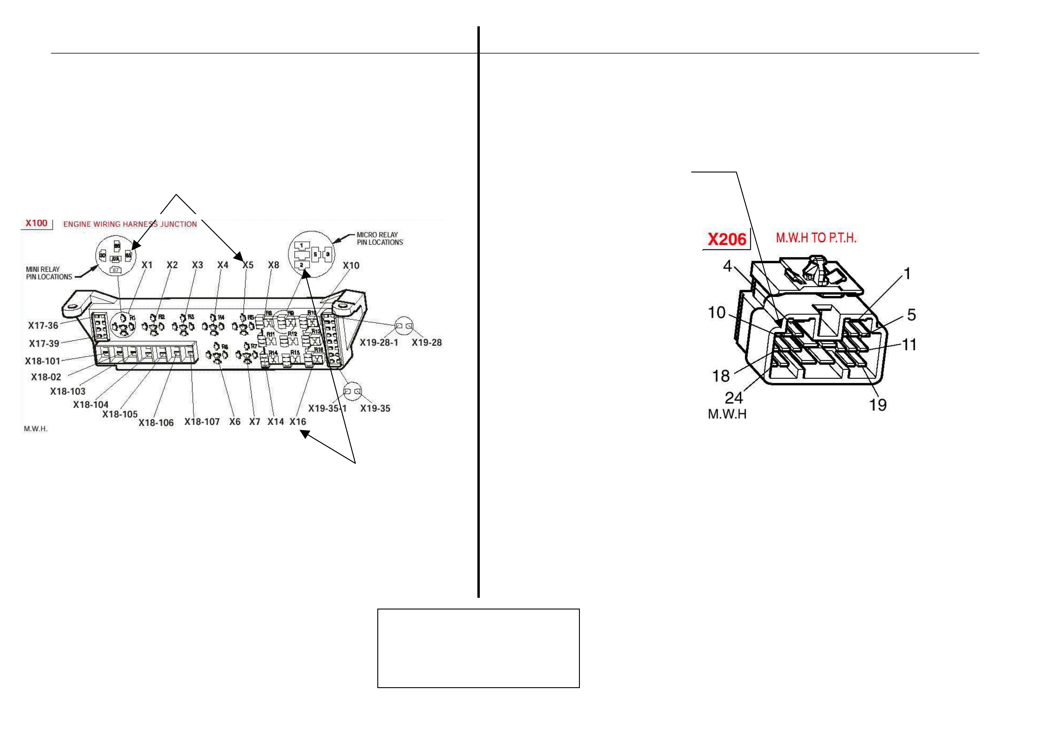
5 Remove the EFI relay and back probe terminal 85 (as per f igure 3 for
WL Vehicles), with reference to Ground.
With the Ignition switch to ON, measure DC voltage.
_____________
volts DC.
6 Remove Fuel Pump relay and back probe terminal.2 (as per figure 3
for WL Vehicles), to measure continuity with ref. to Ground.
Turn the ignition to ON, measure resistance.
_____________
Ohms.
7 For WL Vehicles Disconnect Engine Conn ector (YE112) and back
probe pin (as per figure 2), with referenc e to Ground.
Turn the ignition to ON, measure DC voltage.
_____________
volts DC
8 Is communications with Tech 2 active?
9 With TDL flashing, operate “Unlock” button o n the Remote Control.
Does the TDL stop flashing?
Dealer Code: __________________________ ISO VIN: ______ ____________ ___________
Vehicle Build Date: ___ _____________ _____
Km’s: _____________________ ESS Pin No: ________________ _____ BCM Part No: ___________________
BCM Barcode No: __________________
This check sheet must signed by the Service Manager. ____________________________ ____________ _
Date: ___________________
Fax the completed copy to Australian Arrow Customer Service. Facsimile: (03) 9775 0954.

Electrical and Instruments Page I-11
HSV – Embedded Security System (ESS) Diagnostic Procedure
Step Action Value Yes No
1 Turn ignition to ON position.
Is one (1) beep audible? Go to Step 2 Go to Step 3.
2 Turn Ignition switch to the Start position.
Does the vehicle start? System O.K,
return vehicle to
customer.
Go to Step 11.
3 Are five (5) beeps audible? Go to Step 13. Go to Step 8.
4 Turn Ignition switch to the Start position.
Does the vehicle start? Go to Step 5. Go to Step 6.
5 Fill in the ESS check sheet and Contact Australian
Arrow Customer Service. Go to Step 5. Go to Step 14.
6 Has there been a BCM replacement?
7 Perform Serial Data Communications diagnostic as
per Holden Service Information, then go to Step 5. Go to Step 9. Recor d numb er of
beeps, then go to
Step 5.
8 Zero beeps were audible? Go to Step 5. Go to Step 10.
9 Turn Ignition switch to the Start position.
Does the vehicle start? 12 volts
DC. Go to Step 5. Refer to Service
Information and
check Ignition
system.
10 Remove the EFI relay and back probe terminal 8 5
(as per figure.3 for WL vehicle), with reference to
Ground.
With the Ignition switch to ON, Is the value as
specified?
Less than
one (1)
Ohm.
Go to Step 12. Go to Step 5.
11 Remove Fuel Pump rela y and back probe terminal.1
(as per figure.3 terminal.2 for WL vehicle), to check
continuity with reference to Groun d.
Turn the ignition to ON. Is the value as specified?
12 volts
DC Go to Step 5. Go to Step 5.
12 For WL vehicle, Disconnect Engine Connector (X206
located above passenger kick panel), and back
probe pin.9 (as per figure.4), with reference to
ground.
Turn the ignition to ON. Is the value as specified?
VALUE YES NO
13 Is the Theft Deterrent Led flashing? Go to Step 4. Go to Step 5.
14 Is communications with Tech 2 active? Go to Step 15. Go to Step 7.
15 With TDL flashing, operate “Unlock” button on the
Remote Key.
Does the TDL stop flashing?
Go to Step 5. Refer to Theft
Deterrent System
diagnostics in Holden
Service Information.
Electrical and Instruments Page I-12
Fuel pump relay ( X1 6)
Refer to diagnostic STEP 11
Back probe terminal 2
EFI relay (X5)
Refer to diagnostic Step 10
Back probe terminal 85
Refer to diagnostic step 12 (Pin 9)
A
ustralian Arrow Pty Ltd.
Customer Service
Telephone: (03) 9785 0792

Electrical and Instruments Page I-13
4 HSV Fog Lamps
4.1 General Information
HSV Fog/cornering lamps are fitted directly to the front fascia of all HSV WL Grange models. The HSV lamps us e a glass
convex reflector to provide a wide-an gle beam concentrated in a range of 30 to 40 metres in front of the lamp. The
external lens incorporates a clear horizontal section.
• Fog lamps should be onl y used in adverse weather condition, i.e. fog.
• Use of fog lamps on hot sunny days may res ult in failure from overheating.
• Fog lamps are not daylight running lights.

Electrical and Instruments Page I-14
4.2 Service Operation
Refer to Section 12B Lighting System, of the Holden WL Service Information.
12C-031301 LAMP FOG/ LH
12C-031302 LAMP FOG/ RH
NOTE
Condensation may appe ar on the lense of the fog
lamp when appropriate ambient conditions exist.
This condensation will clear as the ambient
conditions change or after four or five minutes
operation of the fog lamps

Electrical and Instruments Page I-15
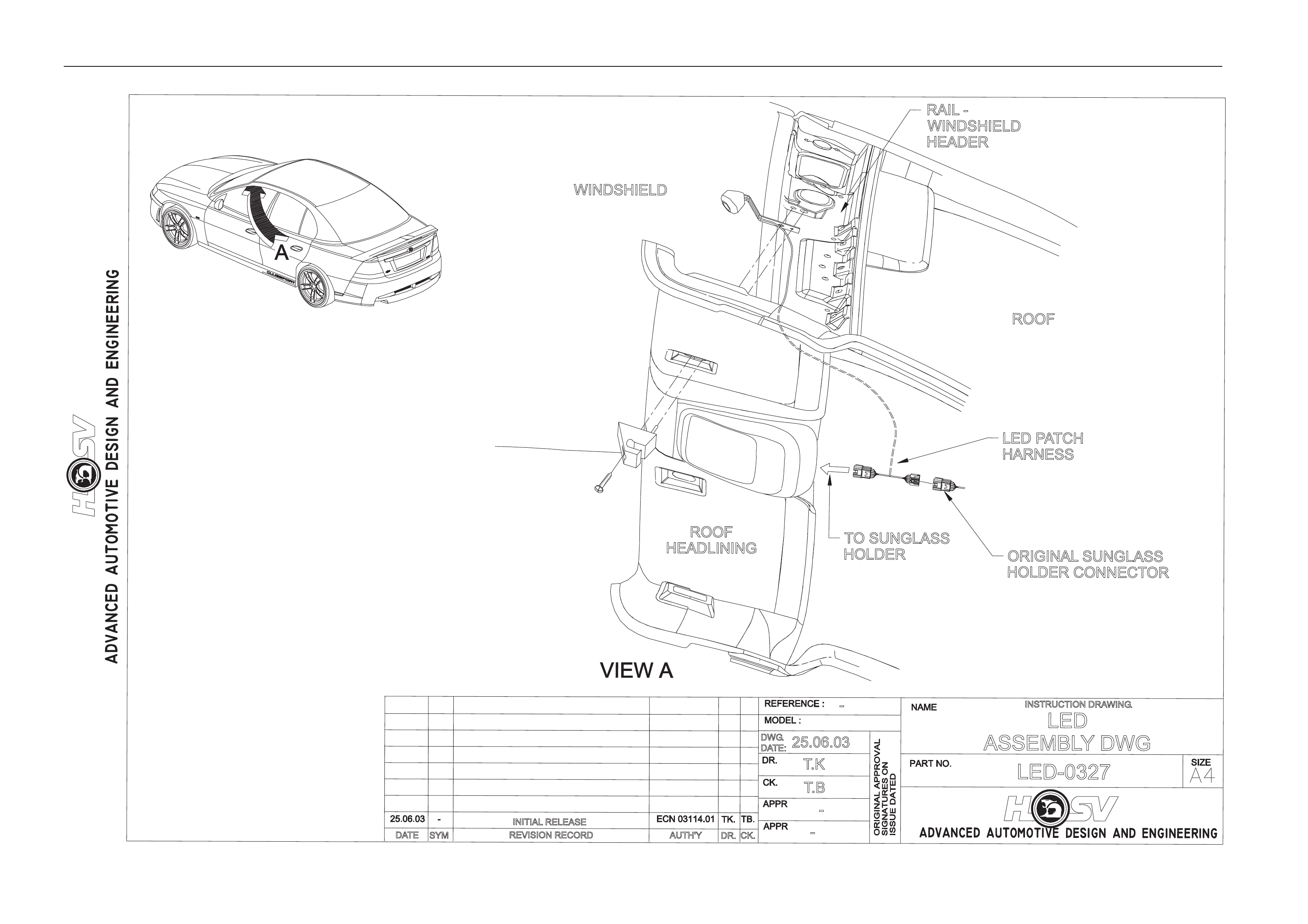
5 L.E.D. Interior Affect Lighting
All HSV WL Series are fitted with L.E.D. Interior Affect Lighting.
The L.E.D. is housed in a small plastic bezel that is heat staked to a brac ket. The bracket is mounted between the
left hand sun-visor hook and t he sheet metal of the vehicle.
The L.E.D. should turn on when the vehicle is un locked using the remote ke y FOB and extinguish 10 seconds after
the car is locked.
The L.E.D. is an effect light that is suppos ed to give a dim wash of light across the centre console and left side of the
dashboard. It is NOT a reading or courtesy lamp.
The L.E.D. is not a serviceab le item and should be replaced if damaged. An electrical represe ntation is given under
the drawing labelled LED-0327
Electrical and Instruments Page I-16
REVISION RECORD
SYM
DATE
INSTRUCTION DRAWING
.
-
AUTH'YCK.
DR.
-
T
.K
T
.B
25.06.03
DWG
.
DATE:
LED-0327
-
LED
ASSEMBLYDWG
INITIAL RELEASE
ROOF
HEADLINING
WINDSHIELD
RAIL -
WINDSHIELD
HEADER
ROOF
TO SUNGLASS
HOLDER ORIGINAL SUNGLASS
HOLDER CONNECTOR
LED PATCH
HARNESS